oscilloscope calibration · oscilloscope display geometry before it is possible to calibrate the...
TRANSCRIPT

Oscilloscope Calibration
A Guide to Oscilloscope Calibration usingDedicated or Multiproduct Calibrators
Application Data

2
User RequirementsOscilloscopes are very complexinstruments, mainly because ofattempts to provide easy anddirect access to waveforms,then to permit both qualitativeand quantitative analysis.
Users demand enough flexibility to deal with a widerange of functions, frequenciesand voltages without having tobuy an array of instruments.
Need for Calibration
Older Low-Cost OscilloscopesAt the low-cost end of therange of oscilloscopes, we canremember older analog instruments, with deflectionaccuracy and bandwidth solimited as to present merely arough picture of a signal.Power supplies were oftenunregulated and there was noexternal means of X/Y gain orbandwidth adjustment.
The accuracy of such aninstrument was seriouslydegraded by fluctuations in theline supply, accompanied bycomponent temperature andtime drift. These types ofinstruments possessed poorperformance repeatability, andcalibration would have beenlargely a waste of time;nowadays, however, calibrationwill more often be required.
Modern Developments inLow-Cost OscilloscopesModern Low-cost instrumentsare vastly different from theolder image presented above.Many newer low-cost oscilloscopes have resulted as aspin-off from the developmentof more expensive and sophisticated instruments, withsignificant improvements incomponent quality, performancerepeatability, and expandedfunctionality.
The advent of more stringentquality standards (such as theISO 9000 series), bringinginsistence on traceability forqualifying measurement systems,now emphasizes the need tocalibrate even low-costoscilloscopes.
More SophisticatedOscilloscopesIn many cases, these are morespecialized instruments, concentrating on such featuresas multi-channel comparison,computation, data collectionand dual-sourced Y-axis deflection. (e.g. presenting bothtime and frequency basessimultaneously on the samescreen).
Oscilloscopes passed througha phase of using a mainframe,with plug-in modules carryingspecialized hardware.Subsequently, with theintroduction of microprocessors,the development of the DigitalStorage Oscilloscope (DSO)permits functionality to bemore-effectively controlled bysuites of software, allowingspecialist programs to disposeof much of the specializedhardware.
DSOs have many advantageswhen the signal is repetitiveand can be retained forexamination by inbuiltmeasurement programs andsignal transfer to other systems(e.g. for pass/fail tests orhard-copy printing). They canalso capture and displaypre-trigger, single-event andshort-lived waveforms whichpresent difficulties with analogoscilloscopes. Some transientscannot be displayed on analogoscilloscopes with sufficientlight output to be viewedconveniently, but capture in aDSO permits enhancement ofthe light output.
Because the DSO dependslargely on sampling techniques,for some applications thiscannot replace the purer'real-time' nature of the signals.For example, when viewingamplitude modulated waveformsand jitter signals on a DSO,'aliased information' candistort the presentation due tothe need for incompatiblesampling rates.
Calibration RequirementsDespite the growing increase inoscilloscope functionality, theessential features of faithfuland accurate representationremain few:
• Vertical deflection coefficients• Horizontal time coefficients• Frequency response• Trigger response
Techniques and proceduresfor calibration must measurethese features, while copingwith the functional conditionswhich surround them. Goodmetrological practice must beused to ensure that anoscilloscope's performance atthe time of use is comparablewith that observed andmeasured during calibration.This will provide confidence incertificates of traceability anddocumentation which resultfrom calibration.
Manual or AutomatedCalibration?Manual calibration methods arewell established, and for analogoscilloscopes there is possiblyno cost-effective alternative,although techniques are beingdeveloped which employ oscilloscope calibrators togetherwith memorized calibrationprocedures directed at individualoscilloscope models. These procedures use a form ofprompted' manual calibration.
For DSOs, which are basedon programmable digitaltechniques, and may already beprogrammed to respond toremote signals (say via theIEEE-488 interface), automatedcalibration can be achieved,with great benefits torepeatability, productivity,documentation generation, andstatistical control.
This guide is intended as anintroduction to the basictechniques of oscilloscopecalibration, and will concentrateon the types of tests andadjustments which are likely tobe used by both manual andautomated methods, and notdifferentiating between them.

Oscilloscope DisplayGeometryBefore it is possible to calibratethe main parameters it is necessary, for many oscilloscopes,to ensure that the essentialgeometry of the oscilloscope isset up correctly. This may, infact, be regarded as part of thecalibration process, as theparameter measurements aredependent on visual observations.
In real-time (analog)oscilloscopes, the graticule is aseparate entity from the screenimages. This means that if thegraticule is to be used as ameasurement tool, alignment toit must be included in thecalibration process. Theinnovation of the ElectronicGraticule in DSOs has largelyremoved the need to establishgeometrical links betweenscreen data and the graticule —this is done automatically, andtube rotation does not disturbrelative alignments.
Where an electronic cursoris used, this links internallywith trace data and channelsensitivities, tied to an internalDC Voltage standard. In thesecases the main requirement isto calibrate the voltage standard.
Parameters to be CalibratedAt this point, it may be usefulto provide a list of theparameters which need to beverified or calibrated in order toensure traceability in themajority of oscilloscopes. Thislist breaks down the featureslisted earlier:
• Accuracy of vertical deflection• Range of variable vertical
controls• Vertical channel switching• Accuracy of horizontal
deflection• Accuracy of any int. calibrator• Pulse edge response• Vertical channels bandwidth• Z-axis bandwidth• X-axis bandwidth• Horizontal timing• Timebase delay accuracy• Time magnification• Delay time jitter• Standard trigger functions• X-Y phase relationship
Parameter DetailsGeometry SetupAlthough setting up the displaygeometry may not be strictlyregarded as a calibrationparameter, the oscilloscope display is the window throughwhich most of the (visual)measurements are made. Thedisplay geometry should be setup, or at least examined, beforegoing ahead with calibration, ifonly to ease the measurement processes. Examples of geometry features are:
• CRT alignment• Earth's field screening or
compensation• Range of focus and intensity • controls, Barrel distortion• Pincushion distortion• Range of Y- and X-axis
positioning controls
Vertical DeflectionAccuracyAmplitudeThe Y-axis is used, almostexclusively, for displaying theamplitude of incoming signals.These are processed through'channel' amplifiers (mainlytwo channels, often four ormore).
Basic setup features include:
• Zero alignment to graticule (Offset)
• Vertical amplifier balance• Vertical channel switching• Operation of alternate/
chopped presentations
Multiple-traces are createdusing alternate-sweepswitching or 'chopped'high-speed switching. Inalternate-sweep switching, thetrace completes beforeswitching to the next. With'chopped' high-speedswitching, usually used for lowfrequency signals, inputs aresampled alternately at highspeed and steered into separatechannels. DSOs use differentforms of switching to achievesimilar effects. Whicheversystem is in use, there will be aseries of alternative channelamplifiers and attenuatorswhose gain characteristics arethe major influence on verticalaccuracy.
3
Fig. 1.1 Standard Graticule

There are five mainparameters to be checked incalibrating each verticalamplifier system: offset, gain,linearity, bandwidth and pulseresponse.
These parameters are crucialto achieve accuraterepresentation of the signal. Foreffective comparisons betweensignals applied through differentchannels, their channelparameters must be equalized.
Measurement of a channelamplifier's gain is usuallyperformed by injection of astandard signal andmeasurement of its presentationagainst the display graticule.Because the amplifier couplingmay be switched betweenAC/DC and often 50Ω/1MΩ, itwill be necessary to injectsignals which test the operationof each of these forms ofcoupling.
Two standard signals formeasuring an amplifier's gainare usually employed:
i. With DC coupling, either a DCsignal (Fig 1.2 - includes offset)or a square wave (Fig. 1.3 -canbe manipulated to remove theoffset) is injected, and thechannel's response is measuredagainst graticule divisions orcursor readings.
All Fluke scope calibratorsprovide DC Voltage and 1kHzsquare wave outputs for testingthe gain and offset of DCcoupled amplifiers.
ii. With AC coupling, a squarewave signal is injected at 1kHz,and again the channel'sresponse is measured againstgraticule divisions or cursorreadings.
Using a low frequency pulsecan also provide a rough checkof the gross LF and HF response(Fig 1.4). This is only a veryrough test of gross distortion. Aresult which looks square muststill be checked for pulseresponse and bandwidth.
All Fluke scope calibratorsprovide a 1kHz square wave fortesting the LF gain ofAC-coupled amplifiers.
Channel amplifiers' linearitycan be tested by injectingeither a DC or a square wavesignal, varying the amplitudeand checking the changesagainst the graticule or cursorreadings.Pulse ResponseViewing the rise time of pulsefast edges is one of two complementary methods ofmeasuring the response of thevertical channel to pulsedinputs (the amplifier's bandwidth should also bemeasured - refer to the sectionChannel Bandwidth).
Response to fast edgesdepends on the inputimpedance of the oscilloscopeto be tested. Two standardinput impedances are generallyin use: 50Ω and 1MΩ//(typically)15pF. 1M Ohm is the industrystandard input generally usedwith passive probes. Where the50Ω input is provided it givesoptimal matching to HF signals.
To measure the rise time,the pulse signal is injected intothe channel to be tested; thetrigger and time base areadjusted to present ameasurable screen image, andthe rise/fall time is measuredagainst the graticule or cursorreadings. The observed rise/falltime has two components: thatfor the applied signal and thatfor the channel under test. Theyare combined as the root of thesum of squares, so to calculatethe time for the UUT channel, aformula must be used:
UUT rise/fall time =Square Root [(Observed time)
2-
(Applied signal time)2
]
4
Fig. 1.2 DC Voltage - Gain
Fig. 1.3 LF Square Wave - Gain
The peak-to-peak value shown onthe screen (b) is compared with theknown value (a):b ÷ a = Gain at 1KHz
Fig. 1.4 LF Square Wave - Distortions

5
In some oscilloscopes thevertical graticule is speciallymarked with 0%, 10%, 90%and 100% to make it easy toline up the pulse amplitudeagainst the 0%/100% marks,then measure the 10%/90%crossing points against markson the center horizontalgraticule line.MeasurementIn all Fluke Models, two differentsort of pulses are used:
• Low Edge Function; a lowvoltage amplitude pulsematched into 50Ω with arise/fall time less than or equalto 1ns. When using the formulato calculate the UUT rise/falltime, the applied signal risetime must be that certified atthe most-recent calibration ofthe calibrator, closest to theamplitude of the applied pulse.
• High Edge Function; a highvoltage amplitude pulsematched into 1MΩ with a risetime less than or equal to100ns. This function is usedmainly to calibrate theresponse of the oscilloscope'schannel attenuators.Leading-Edge AberrationIn Fig. 1.5, some leading-edgeaberrations (overshoot andundershoot) are shown at thetop end of the edge, before thevoltage settles at its final value(which is the value defined as100%).
Where scope specificationsinclude aberrations, thespecification limits can beexpressed as shown in theshaded area of the magnifiedFig. 1.6 (typical limits shown).
When aberrations aredisplayed for measurement,they should be within thespecification limits, althoughwhere the oscilloscope'saberration specificationapproaches that of the calibrator,other methods must be used.
Channel BandwidthAs well as determining thepulse response by viewing aspecimen pulse on the screen,this should be supported bymeasuring the amplifier'sbandwidth using a 'leveledsine wave'. This is done at aninput impedance of 50Ω, tomaintain the integrity of the 50Ω source and transmissionsystem. For high input impedance oscilloscopes, an in-line 50Ω terminator is usedto match the line at the oscilloscope input. The in-line50Ω could take the form of aseparate 50Ω terminator or beincorporated within an ‘Active’head - the latter gives thebenefit of full automation andrequires no additional calibration.
First the displayed amplitudeof the input sinusoidal wave ismeasured at a referencefrequency (usually 50kHz), thenthe frequency is increased, atthe same amplitude, to thespecified 3dB frequency of thechannel. The displayedamplitude is measured again.
The bandwidth is correct ifthe observed 3dB pointamplitude is equal to or greaterthan 70% of the value at thereference frequency.
If it is needed to establishthe actual 3dB point, thefrequency should be increaseduntil the peak-to-peakamplitude is 70% of the valueat the reference frequency,then this frequency is close tothe 3dB point.
Fig. 1.5 Measurement of Rise Time
Fig. 1.6 Leading Edge Aberration
Fig. 1.7 Setting the Amplitude at theReference Frequency
Fig 1.8 Measuring the Amplitude atthe 3dB Point Frequency
6
Horizontal DeflectionAccuracyIntroductionThe X-axis is dedicated almostexclusively to use as the vehiclefor the time base(s). As well astwo vertical channels, therewill often be two time bases:Main and Delayed. These maybe achieved in DSOs by twoindependent sampling rates, orvia a positioned 'zoom' windowon a single, but long, store.
When determining theaccuracy of horizontal deflection,where applicable, the geometryof the display must have firstbeen set up. It is assumed thatthis will be included as part ofthe initial geometry setup.
Once this has been done,the following adjustments orchecks can be attempted:
• X-axis bandwidth• Horizontal timing• Timebase delay accuracy• Time magnification• Delay time jitter• Trigger functions• X-Y phase relationship
X-Axis BandwidthFor real-time oscilloscopes, thehorizontal amplifier's bandwidthwill be checked using a 'leveledsine wave', similar to thechecks of vertical channels, butwith the time base turned off.This consists first of measuringthe displayed length of thehorizontal trace (Fig. 1.9), for asinusoidal wave provided as Xinput at a reference frequency(usually 50kHz).
The frequency is thenchanged, at the same amplitude,to the specified 3dB point ofthe horizontal amplifier and thedisplayed trace length ismeasured again (Fig. 1.10). Thebandwidth is correct if theobserved 3dB point tracelength is equal to or greaterthan 70% of the length at thereference frequency.
DSOs generally employ avertical channel amplifier asthe horizontal amplifier, sohaving measured the verticaldeflection bandwidth, there isgenerally no need to measurehorizontal deflection bandwidth.
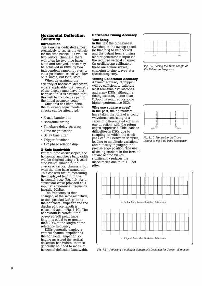
Horizontal Timing AccuracyTest SetupIn this test the time base isswitched to the sweep speed(or time/div) to be checked, and the output from a timingmarker generator is input viathe required vertical channel.On oscilloscope calibratorsthese are square waves,changing to sine waves at aspecific frequency.Timing Calibration AccuracyA timing accuracy of 25ppmwill be sufficient to calibratemost real-time oscilloscopesand many DSOs, although atiming accuracy better than0.3ppm is required for somehigher-performance DSOs.Why use square waves?In the past, timing markershave taken the form of a 'comb'waveform, consisting of aseries of differentiated edges inone direction, with the returnedges suppressed. This leads todifficulties in DSOs due to sampling, in which the combpeak can fall between samples,leading to amplitude variationsand difficulty in judging theprecise edge position. The useof timing markers in the form ofsquare or sine waves significantly reduces the inaccuracies due to this 1-dotjitter.
Fig. 1.9 Setting the Trace Length atthe Reference Frequency
Fig. 1.10 Measuring the TraceLength at the 3 dB Point Frequency
Fig. 1.11 Adjusting the Marker Generator’s Deviation for Correct Alignment
a. Initial State before Deviation Adjustment
b. Aligned State after Deviation Adjustment

MeasurementThe marker timing is set toprovide one cycle per divisionif the horizontal timing is correct.
By observation, the markergenerator's deviation control isadjusted to align the markerson the screen behind theircorresponding vertical graticulelines, and the applied deviationis noted. The applied deviationshould not exceed theoscilloscope's timing specification.
The operation is repeated forall the sweeps and time basetime/division settings designatedfor calibration by theoscilloscope manufacturer.Time Base Delay AccuracyFor this test it is assumed thatthe delayed time base is indicated as an intensificationof the main time base, and canbe switched to show thedelayed time base alone. For alloscilloscopes, ensure that theretrigger mode is switched off.
The output from a timingmarker generator is input viathe required vertical channel,and the oscilloscope is adjustedto display one cycle per divisionas illustrated in Fig 1.12 a.The oscilloscope mode switchis set to intensify the delayedportion of the main time baseover a selected marker edge asshown (this may require someadjustment of the oscilloscope'sDelay control).
The oscilloscope delay modeswitch is set to display thedelayed sweep alone, and thedelay control is adjusted toalign the time marker edge to achosen vertical datum line (e.g.center graticule line as shownat Fig 1.12 b). The setting ofthe oscilloscope's delay isnoted.
The oscilloscope modeswitch is set to intensify thedelayed portion of the maintime base over a differentselected marker edge -(Fig. 1.13 a).
The oscilloscope delay modeswitch is again set to displaythe delayed sweep alone, andthe delay control is adjusted toalign the time marker edge tothe same vertical datum line(Fig. 1.13 b). The setting of theoscilloscope's delay is againnoted.
Finally, the two settings ofthe oscilloscope delay arecompared, to check that theirdifference is the same as thetime between the two selectedmarkers, within the specifiedlimits for the oscilloscope.Horizontal X10 MagnificationAccuracyThe output from a timing markergenerator is input via therequired vertical channel, andthe oscilloscope is switched to display 10 cycles per divisionas illustrated in Fig 1.14 a.
The timing marker generatorfrequency/period is adjusted togive exactly 10 cycles per division.
The errors are likely to begreatest on the right of thetrace (the longest time after thetrigger), so the oscilloscope'shorizontal position control isadjusted to place the markeredge at 'A' at the center of thescreen.
7
a. Delayed Time Base Intensified on the Main Time Base
a. Delayed Time Base Intensified on the Main Time Base
b. Delayed Time Base Alone with Datum marker
b. Delayed Time Base Alone with Datum marker
Fig. 1.12 Adjusting the Delayed Time Base to the First Datum Marker
Fig. 1.13 Adjusting the Delayed Time Base to the Second Datum Marker

The oscilloscope is set todisplay the X10 sweep, and thehorizontal position control isadjusted to align the markeredge 'A' exactly to the centergraticule line.
The marker generatorFrequency/Period deviationcontrol is adjusted to align themarker edges exactly to thegraticule lines as shown at Fig1.14 b.
The marker generatorFrequency/Period deviationsetting is noted. This settingshould be within the specifiedlimits for the oscilloscope.
Similarly, for a DSO, therange of available 'Zoom' orX-magnification' factors arecalibrated as designated by themanufacturer.Delay Time JitterThe delay jitter on oscilloscopesis often measured under timemagnifications of the order of20,000:1. This means that thedelayed time base must run20,000 times faster than themain time base (for a maintime base running at 20ms/div,the delayed time base must runat 1µs/div).
For this test theintensification of the main timebase is adjusted onto the edgeat the center graticule line(with such a differencebetween the speeds of themain and delayed time bases, avery small part of the maintime base is intensified, andadjustment may be difficult).
The 20ms period outputfrom a timing marker generatoris input to the required verticalchannel, and the oscilloscope isadjusted to display one cycleper division (20ms/div) asillustrated in Fig 1.15a.
The delayed time base is setto run at 1µs/div, and theoscilloscope mode switch is setto intensify the delayed portionof the main time base over thecenter marker edge as shownusing the oscilloscope's delaytime control.
The oscilloscope delay modeswitch is set to display thedelayed sweep alone, and thedelay control is adjusted toalign the time marker edge to achosen vertical datum line (e.g.center graticule line as shownat Fig 1.15b).
The width of the verticaledge (which displays the jitter)of the displayed portion of thewaveform, measured along ahorizontal axis, should notexceed the oscilloscope'sspecified jitter limits (i.e. in thisexample, for 20,000:1specification, the oscilloscope'scontribution to the widthshould be less than 1 division).
Trigger OperationStandard Functions —IntroductionFor most oscilloscopes, a widevariety of trigger modes exist,being sourced either via anominated Y-input channel, orfrom a separate ExternalTrigger input.
The functionality of the triggermodes allow for AC or DCcoupling, repetitive or single-sweep, and Trigger-Levelcontrol operations.
These tests check theoperation of:
• Internal trigger sensitivity in both polarities, from each of the available Y-input channels.
• Operation of the Trigger LevelControl for a sinewave external trigger input.
• Effect of Vertical Position on trigger sensitivity,
• Minimum trigger levels for normal and 'trigger view' modes.
• Bandwidth of trigger circuits, and effect of HF rejection filters.
• LF and DC performance of thetrigger circuits.
• Single-sweep performance and response to position controls.
Note:Note: Tests which are per-formed using a Y-channel inputare also carried out on all theother available Y-channels.
8
Fig. 1.14 Checking the Effect of X10 Magnification Fig. 1.15 Measuring the Delay Time Jitter
a. Markers Set at 10/div at X1 Magnification a. Delayed Time Base Intensified on Main Time Base
b. Markers Set at 10/div at X10 Magnification b. Edge Showing Jitter on Delayed Time Base

Internal Triggers — TriggerLevel Operationa. Initial SetupA standard 4Vp-p (50Ω)reference sinusoidal signal isinput via AC coupling into theY-input Channels in turn. Usinginternal triggers and DC triggercoupling (not 'AUTO'), the +veand -ve slopes are selected inturn. The sweep speed settingis 10µs/division; the Y-channelsensitivity is 0.5V/division sothat the input signal occupies 8divisions.b. Trigger Level AdjustmentOver almost all of its range ofadjustment, the Trigger Levelcontrol must be shown to produce a stable trace, movingthe starting point over a rangeof levels up and down theselected slope of the displayedsine wave.c. Trigger SensitivityWith the input signal reducedto 10% of its amplitude, adjustment of the Trigger Levelcontrol must be shown to reacquire stable triggering.With trigger coupling switchedto AC, and using verticalpositioning to place the trace atextreme upper and lower limitsof the CRT screen in turn, stabletriggering must be maintained.d. 'Display Triggers' FeatureIf the oscilloscope has a 'DisplayTriggers' or 'Trigger View' feature, this is selected to display the trigger region of thewaveform. Using a 200mVsinusoidal signal input to thechannel, the trigger region ischecked for correct amplitudeon the display.
N.B. In the following triggeroperations, during tests on aDSO, the trace will notdisappear as a result of theinterruption of the trigger (orreduction of its amplitudebelow the threshold). Instead,the trace will remain but not berefreshed, and this is the condition to be detected.
External Triggersa. Initial SetupThese tests start with the200mV signal, described in theprevious paragraph 'DisplayTriggers' Feature, applied to theExternal Trigger input of theoscilloscope.b. Presence of a TraceAdjustment of the oscilloscope'sTrigger Level control should beable to produce a trace. The ExtTrig input is disconnected andreconnected again, whilechecking that the trace disappears and is then reinstated.c. Trigger SensitivityWith the input signal reducedto the minimum amplitudespecified by the manufacturer,adjustment of the Trigger Levelcontrol must be shown toregain stable triggering.d. Trigger BandwidthWith the input signal set to theminimum amplitude and maximum frequency specifiedby the manufacturer, adjustmentof the Trigger Level controlmust be shown to acquire stabletriggering. The Ext Trig input isdisconnected and reconnectedagain, while checking that thetrace disappears and is thenreinstated.e. ACHF Rejection TriggerModeWith the input signal set as forthe Trigger Bandwidth check,the ACHF Reject feature isactivated then deactivatedagain, while checking that thetrace disappears and is thenreinstated.Internal Triggers — DC-Coupled Operation
a. Initial SetupWith the Ext Trig input disconnected, and the Y-channelinput externally grounded, theoscilloscope Y-channel is set to'DC-coupling' and trigger modefor 'internal triggers' from theY-channel. There should be notrace on the CRT.b. DC TriggeringBy adjusting the VerticalPositioning control to passthrough a point in its rangecorresponding to the TriggerLevel setting and selected slopedirection, a single trace shouldappear then disappear.
c. ACLF Rejection TriggerModeWith the input signal set as forthe Trigger Bandwidth check,the ACLF Reject feature (ifavailable) is activated andparagraph (b) is repeated. Thesingle trace action should notoccur.External Triggers —Single-Sweep Operationa. Initial Setup(Applies only to those scopeswith Single Sweep capability)With the Ext Trig input connected, the oscilloscopeis set to 'Single Sweep', andtrigger mode for 'InternalTriggers' from the Y-channel.There should be no trace onthe CRT.b. Single Sweep TriggeringPressing the 'Reset' or 'Rearm'switch should produce a singletrace. This action should notproduce a trace when the ExtTrig input is disconnected.Low Frequency Triggersa. Initial SetupA 30mV, 30Hz sinewave signalis input simultaneously toChannel 1, Channel 2, Ext TrigSweep A (main time base) andExt Trig Sweep B (delayed timebase). The oscilloscope is setfor: trigger mode to 'InternalTriggers', Channels 1 and 2sensitivity to 10mV/div, andsweep speed to 5ms/div. Bothmain and delayed time basesshould be displayed whenselected, for both channels.b. Channel 2 GroundedWith Channel 2 input grounded,and Channel 1 set for 0.1V/divwith the trigger selector set toChannel 1, stable displaysshould appear as expected.c. Channel 1 GroundedWith Channel 1 input grounded,and Channel 2 set for 0.1V/divwith the trigger selector set toChannel 2, stable displaysshould appear as expected.d. ACHF RejectWith Channel 2 input grounded,and Channel 1 set for50mV/div with the triggerselector set to Channel 1, theACHF Reject feature is activatedfor both Sweeps A and B.Adjusting the Trigger Levelcontrol should acquire a stabledisplay.
9

e. Positive and NegativeSlope OperationWith Channel 2 input grounded,and Channel 1 set for 10mV/divwith the trigger selector set toChannel 1, adjusting theTrigger Level control shouldacquire a stable display forboth + and -slope selections.f. ACLF RejectWith Channels 1 and 2 set for10mV/div with the triggerselector set to either channel,the ACLF Reject feature is activated for both Sweeps Aand B. Adjusting the TriggerLevel control should not beable to acquire a stable displayfor either + or - slope selection.
Z-AxisZ-Axis InputIf provided, the Z-axis input isusually positioned on the rearpanel, but sometimes can befound near the CRT controls onthe front panel. DSOs generallydo not have a Z-input.Z-Axis Bandwidtha. Initial SetupA 3.5Vp-p, 50kHz sinewave isapplied to both Channel 1 andExt Trig inputs. The sweepspeed, trigger slope and triggerlevel controls are set to providea stable display of 1 cycle perdivision.b. Signal Transfer to Z InputThe signal input to Channel 1is disconnected and transferredto the Z-axis input. the traceshould collapse to a series ofbright and dim sections. Usingthe oscilloscope brightnesscontrol, the trace is dimmed sothat the brightened portionsjust disappear.c. Bandwidth CheckThe frequency of the inputsinewave is increased to theexact specified Z-axis bandwidthpoint. The amplitude of thesinewave is increased to 5Vp-p.Adjustment of the sweep speedand trigger level controls shouldacquire a dotted, or intermittently brightened trace.
X-Y PhasingX InputDepending on the type of oscilloscope, the X input will beapplied either via the ExternalTrigger connector, or viaChannel 1, with suitableswitching. In either case, thesame signal of 50mV, 50kHzwill be applied to both X and Yinputs.Phasing Testa. Initial SetupThe oscilloscope controls areset as follows:
Vertical mode: X-Y;Sensitivity: 5mV/div,
both channelsCh 1 or X: AC CoupledCh 2 or Y: GroundedVertical mode: X-YVertical position: CentralHorizontal position: Central
N.B. During X-Y phasingtests on a DSO, maximumsampling rate would be used.Even so, the visible extent ofany captured lissajou is limitedto interrupted segments by thestore length, until the testfrequency is high enough foran entire cycle to be captured.b. Trace AcquisitionThe display intensity is adjusteduntil a horizontal trace is justvisible (should be 10 divisionslong). After the X and Y positioncontrols have been used tocenter the trace, the intensityand focus controls are adjustedfor best display.
10
c. Phasing CheckThe common input signal isreduced until the trace is 8divisions long. Channel 2 (or Y)input mode is switched to DC,and the X and Y positioncontrols are used to center the(now sloping) trace. If the Xand Y channels do not introduceany phase error, then the centerof the trace will pass throughthe origin. Phase error betweenX and Y channels will causethe sloping trace to split intoan ellipse, which for smallphase errors will be apparentonly close to the origin. Thetrace separation at the origin,along the center horizontalgraticule line, should be notgreater than 0.4 division for acommonly-specified phase-shiftof 3 degrees.

11
9500B9500B/600: 600 MHz High-Performance OscilloscopeCalibrator
9500B/1100: 1.1GHz High-Performance OscilloscopeCalibrator
9500B/3200: 3.2 GHz High-Performance OscilloscopeCalibrator
9500 Accessories andOptions9510: Active Head with 500 pspulse risetime
9530: Active Head with 150 psand 500 ps pulse risetime
9550: 25 ps Fixed edge pulseoutput module
9560: 6 GHz Active Head with70 ps pulse risetime*
* Compatible only with the9500B/3200
5500A/5520A5520A: High PerformanceMulti-Product Calibrator
5500A: Multi-ProductCalibrator
5520A-PQ: 5520A Multi-Product Calibrator with PowerQuality Option
5520A-PQ/ 3: 5520A Multi-Product Calibrator with PQ and300 MHz Scope Option
5520A-PQ/ 6: 5520A Multi-Product Calibrator with PQ and600 MHz Scope Option
5520A-PQ/ 1G: 5520A Multi-Product Calibrator with PQ and1 GHz Scope Option
9100 9100: Multi-Product Calibrator
9100 Accessories andOptions9100 - 100: High StabilityCrystal Reference
9100 - 135: Insulation/Continuity Tester CalibrationModule (fitted internally)
9100 - 200: 10/50 Turn Coils
9100 - 600: 600 MHzOscilloscope Calibration Module(fitted internally)
9100 - PWR: Power MeterCalibration Module (fitted internally)
Fluke Oscilloscope Calibrators
Other useful reference material:
Fluke Publications:1612935 A ENG-N 02/2001 “Fully Automated True Bandwidth Testing of High Performance Oscilloscopes”
B0252EEN Rev B 02/97 “How many Calibrators do you need to meet ISO9000”
1282496 A-ENG-N 09/99 “In-House Calibration - Is it best for you”
Websites:www.calibration.fluke.comwww.lecroy.comwww.tektronix.comwww.tm.agilent.com

Fluke Corporation Calibration of Oscilloscopes
Fluke CorporationPO Box 9090, Everett, WA USA 98206
Fluke Europe B.V.PO Box 1186, 5602 BD Eindhoven, The Netherlands
For more information call:In the U.S.A. (800) 443-5853 or Fax (425) 356-5116In Europe/M-East/Africa (31 40) 2 678 200 or Fax (31 40) 2 678 222In Canada (800)-36-FLUKE or Fax (905) 890-6866From other countries (425) 356-5500 or Fax (425) 356-5116Web access: http://www.fluke.com/
©2000 Fluke Corporation. All rights reserved. Trademarks are the property of their respectiveowners.Printed in UK 6/2001 1626187 A-ENG-N Rev A,DS254
Printed on recycled paper.
Fluke.Keeping your worldup and running.
Fluke publishes additionalcatalogs, CD-ROMs andbrochures with informationabout its range of Test andMeasurement solutions(oscilloscopes, timer/counters,signal generators and RCLmeters).
For more information aboutthese publications, contact yourlocal Fluke sales representativeor visit our web site atcalibration.fluke.com
Do You Need Information About
Other Fluke Products?