oss manual 2008 usc update
TRANSCRIPT
8/18/2019 OSS Manual 2008 USC Update
http://slidepdf.com/reader/full/oss-manual-2008-usc-update 1/46
NEW YORK STATE DEPARTMENT OF
TRANSPORTATION
OVERHEAD SIGN STRUCTURE DESIGNMANUAL
May 2008

8/18/2019 OSS Manual 2008 USC Update
http://slidepdf.com/reader/full/oss-manual-2008-usc-update 2/46

8/18/2019 OSS Manual 2008 USC Update
http://slidepdf.com/reader/full/oss-manual-2008-usc-update 3/46
May 2008 i
NEW YORK STATE DEPARTMENT OF TRANSPORTATION (NYSDOT)
OVERHEAD SIGN STRUCTURE DESIGN MANUAL
TABLE OF CONTENTS
1
INTRODUCTION .............................................................................................................1
1.1 Scope .................................................................................................................1
1.2 Background ........................................................................................................1
1.3 General Guidance in Selecting OSS ..................................................................2
1.4 Applicable Specifications....................................................................................3
1.5 Definitions...........................................................................................................4
2
METHOD 1 - STANDARD OSS SELECTION USING BD SHEETS...............................5
2.1 Sign Selection and Layout..................................................................................5
2.2
Electronic BD Sheets..........................................................................................5
2.3 Sign Structure Identification Number.................................................................. 5
2.4 Maximum Post Height .......................................................................................5
2.5 OSS Span or Arm Length ..................................................................................6
2.6 Limitations of the Standard OSS Selection Procedure .......................................6
2.7 Structure Type Selection ....................................................................................7
2.8 Foundation Selection..........................................................................................8
2.9 Cantilever Trussed Arm Spacing Selection ......................................................10
2.10
Additional Information Required on BD-OS1/BD-OS8 .....................................11
2.11 Additional OSS .................................................................................................11
2.12 Assembly of Appropriate BD Sheets for the PS&E .......................................... 11
2.13 Contractor/Fabricator Options ..........................................................................11
3
METHOD 2 - SPECIAL DESIGN - INDEPENDENT ANALYSIS...................................13
3.1 Special Design Applications .............................................................................13
3.2 Overview...........................................................................................................13
3.3 Special Design Procedure ................................................................................14
4
REFERENCES ..............................................................................................................16
APPENDIX A Major Changes from the 1968 Design Manual and the 2000 Interim SteelDesign (EI 00-035)
APPENDIX B Design Assumptions Used for Standard OSS on BD-OS1 Through BD-OS14 APPENDIX C Issues And Options Evaluated During the Development of the Standard OSS
Designs APPENDIX D Foundation Loads at Standard OSS APPENDIX E Example Special Median Support Foundations for Overhead Sign Structures
in Concrete Barrier

8/18/2019 OSS Manual 2008 USC Update
http://slidepdf.com/reader/full/oss-manual-2008-usc-update 4/46

8/18/2019 OSS Manual 2008 USC Update
http://slidepdf.com/reader/full/oss-manual-2008-usc-update 5/46
May 2008 1
OVERHEAD SIGN STRUCTURE DESIGN MANUAL
1 INTRODUCTION
1.1 Scope
This manual describes the procedures to be used to design and detail cantilever and spanoverhead sign structures (OSS) in the State of New York. These procedures shall be used forthe design of all OSS.
Overhead signs include signs over any portion of the roadway, including the shoulders,requiring vertical clearance for vehicles to pass underneath. Overhead signs are used toprovide the traveling public with clear messages under a variety of conditions, directly over theroadway. The National Manual on Uniform Traffic Control Devices for Streets and Highways -(National MUTCD) and the New York State Supplement, contains the requirements for
determining when and where overhead signs should be used.
Typically, overhead signs are supported by OSS. For purposes of this manual, OSS are definedas span or cantilever structures supported on posts, designed to carry signs over the roadway.Less frequently, overhead signs may be supported by cable structures, mounting to bridgefascias or piers, or other unique structural arrangements.
This manual is limited in scope to typical OSS, consisting of post-supported span or cantileverstructures. Non-typical support structures shall be designed on a case by case basis using theparameters and references presented in this manual.
Two separate design/selection methods are presented:
Method 1 STANDARD OSS SELECTION USING BD SHEETS applies only to structures
supporting 1/8 inch (3 mm) thick aluminum sign panels. These standard designs are expectedto cover the great majority of OSS requirements in NYS.
Method 2 SPECIAL DESIGN - INDEPENDENT ANALYSIS is used for OSS that fall outsidethe limits covered by the BD sheet standard selection tables, including those that support signpanels greater than 1/8 inch (3 mm) in thickness.
The scope of this manual does not include design guidance for protection of OSS as fixedobjects, determining the location and type of signs to be supported by the structure, determiningwhether or not an OSS is needed in lieu of a ground mounted sign or traffic pole design. Suchguidance may be found in the Highway Design Manual (HDM) and the National MUTCD withNYS Supplement.
1.2 Background
The Department designed and built OSS using the 1968 Manual in combination with standardSheets and Drawings almost exclusively until October 2000. The 1968 method used aluminumtri-chord trusses with steel posts for spans, and either steel or aluminum elements forcantilevers.
8/18/2019 OSS Manual 2008 USC Update
http://slidepdf.com/reader/full/oss-manual-2008-usc-update 6/46
NYSDOT OSS Design Manual
2 May 2008
The Department recognized that the AASHTO recommendations for forces and loads used inthe design of overhead sign structures had changed since 1968. New factors, including theissue of Heat Affected Zone for welded aluminum structures, fatigue loads and analyses,changes in height and exposure factors, new wind pressure formulas and changes in group
load combination factors were being investigated and incorporated into AASHTO criteria.In addition to the changes occurring in AASHTO criteria, statewide inspection programsrevealed that the most significant and common problem observed was cracked weldedaluminum connections. Further analyses, based on recent AASHTO criteria, have confirmedthat steel welds have 2 to 3 times the Constant Amplitude Fatigue Life (CAFL) as equivalentaluminum welds.
As a result of the new AASHTO criteria and inspection results, the Department issued interimsteel designs for span structures in October 2000 (EI 00-035) and discontinued the use ofaluminum OSS.
1.3 General Guidance in Selecting OSSThe National MUTCD with NYS Supplement continues to be the authoritative source indetermining what signs are necessary and where they are to be located. Ground mounted signsmay be considered in lieu of overhead signs, if permitted by the MUTCD. In all instances, signsshould be placed in a manner that will minimize potential danger and confusion caused bymotorist uncertainty.
When an overhead sign is needed, the proper means of support shall be selected. The followingis basic guidance for typical circumstances and is not intended to be comprehensive.
1. When the signage is intended for the under roadway, use a nearby bridge fascia if thebridge is structurally adequate for the required loads and forces and the skew angle of the
existing bridge is not excessive (depending upon the width of the sign, a skew of up to about40 degrees may be accommodated by the structural mounting attachments). The bridgeshall be located within the limits specified by the MUTCD for the overhead sign. This optionusually has a substantially lower initial cost than an OSS and will minimize traffic disruptionduring future OSS inspections. (Note: Not all bridges are suitable for supporting overheadsigns and standard details do not exist for mounting attachments. The Regional StructuresEngineer [RSE] shall be consulted. A full analysis shall be performed to develop a suitableattachment design for the specific signage.) An analysis is required to determine if thebridge is structurally adequate to support the overhead signage. A load rating calculation,including the signage and its mounting attachment, shall be completed and included in theBridge Identification Number (BIN) folder.
8/18/2019 OSS Manual 2008 USC Update
http://slidepdf.com/reader/full/oss-manual-2008-usc-update 7/46
May 2008 3
2. Avoid using an OSS to span both directions of a divided highway to support signs intendedfor only one direction. Instead, use a structure spanning one direction with a mediansupport, or use a cantilever, depending on the sign location. (Note: A median supportfoundation will involve a special design if it is located within a barrier. See Appendix E for
examples. In other cases it may require protection as a fixed object; see HDM Chapter 10.) An OSS spanning two traffic directions will generally be three to four times more costly thanan equivalent one direction structure due to its greater length and required section.
Additionally, a structure spanning two traffic directions will be approximately twice as costlyto inspect and cause twice the traffic disruption and potential hazard compared to anequivalent one direction structure.
3. Cantilever structures shall generally be used to support signs over the shoulder and/or thetravel lane nearest the post. Long arm cantilevers will generally be more costly thanequivalent spans and are subjected to much greater fatigue loads than span type structures.In addition, they are less redundant than the current dual post, span type OSS standarddesigns. On the other hand, cantilevers with shorter arms for signs over the shoulder or
travel lane nearest the post will generally be less costly to construct and inspect. In certaincases, two small cantilevers may be considered in lieu of an OSS spanning two directions,depending on site specific conditions.
4. Avoid placing an OSS on a bridge when the signage is intended for the over roadway. Thistype of structure requires specially designed post supports and connections. In addition,bridge vibrations may affect the OSS. If there is no alternative to an OSS on a bridge, use aspan structure in lieu of a cantilever. Cantilever structures supported on bridges should beavoided due to the resulting load and force combinations. Note that the standard OSSwere not designed to accommodate fatigue occurring from bridge vibration. A dynamicanalysis will need to be performed on OSS located on bridge superstructures. Also, if a signstructure must be mounted on a bridge, the designer should explore the possibility of usinga concrete pier extension as a support in lieu of the bridge superstructure.
5. Avoid using cantilever structures to support variable message signs (VMS) due to theeccentricity of the VMS dead load, the magnitude of fatigue forces and the potential for outof plane bending.
1.4 Applicable Specifications
1.4.1 Design Specifications
The New York State Department of Transportation Standard Design Specifications forOverhead Sign Structures, latest version.
1.4.2 Construct ion and Material Specifications
The Standard Specifications, Construction and Materials, New York State Department ofTransportation, Office of Engineering (latest version), with all additions and modificationscurrent at time of design.
8/18/2019 OSS Manual 2008 USC Update
http://slidepdf.com/reader/full/oss-manual-2008-usc-update 8/46
NYSDOT OSS Design Manual
4 May 2008
1.5 Definitions
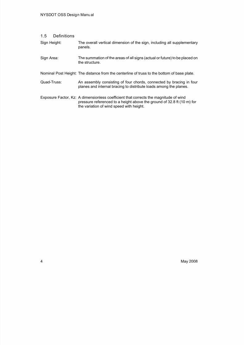
Sign Height: The overall vertical dimension of the sign, including all supplementarypanels.
Sign Area: The summation of the areas of all signs (actual or future) to be placed onthe structure.
Nominal Post Height: The distance from the centerline of truss to the bottom of base plate.
Quad-Truss: An assembly consisting of four chords, connected by bracing in fourplanes and internal bracing to distribute loads among the planes.
Exposure Factor, Kz: A dimensionless coefficient that corrects the magnitude of windpressure referenced to a height above the ground of 32.8 ft (10 m) for
the variation of wind speed with height.

8/18/2019 OSS Manual 2008 USC Update
http://slidepdf.com/reader/full/oss-manual-2008-usc-update 9/46
May 2008 5
2 METHOD 1 - STANDARD OSS SELECTION USING BD SHEETS
BD sheets in the OS series provide a simple procedure for designers to select the appropriateOSS for their project. These BD sheets also include all appropriate details required and shall be
used as contract sheets in the plans, specifications and estimate (PS&E). The BD-OS sheets donot require modification when Method 1 is used. The designer need only enter requiredinformation on BD-OS1 (for span structures) and/or BD-OS8 (for cantilever structures).
The standard selection tables contained in the BD sheets have been developed to satisfy thegreat majority of requirements for typical cantilever and span OSS supporting standard 1/8 inch(3 mm) thick aluminum sign panels, within specified limits as noted in Section 2.6. Whenrequirements for OSS exceed these limits, Method 2 for special design procedures shall beused, as described in Section 3. Special design procedures shall also be used for butterfly,multi-span or combination span and cantilever sign structures.
The procedure for selecting an OSS and completing the BD sheets for incorporation into thecontract plans follows in Sections 2.1 through 2.12. Instructions for the EIC to record the
constructed foundation types are included in Section 2.13.
2.1 Sign Selection and Layout
Determine the size, type and location of sign panels to be supported by the OSS. Evaluatewhether future sign panel size increases are likely. If changes are expected, the sign structureshall be designed to accommodate the larger of either the current or future sign area. Determinethe total sign area to be supported by the OSS by summing all sign panel areas.
Based on the sign locations and sign areas, determine if a span or cantilever type OSS isneeded. Generally, cantilever structures should only be used to support signs over the shoulderor lane closest to the post. (Note: Refer to Section 2.6 and BD-OS2 / BD-OS9 for limitations onspan and cantilever structures.)
2.2 Electronic BD Sheets
Electronic copies of the BD sheets BD-OS1 through BD-OS14 are located on the DepartmentWeb site at: https://www.nysdot.gov/portal/page/portal/main/business-center/engineering/cadd-info/drawings/bridge-detail-sheets .
2.3 Sign Structure Identification Number
The Regional Structures Engineer (RSE) will maintain a list of sign Structure IdentificationNumbers (SINs) for all OSS in the State and will issue a number for each new OSS. Contact theRSE to obtain the SINs for the OSS in the contract. Insert these numbers into the fill-in tables inthe contract plans on BD-OS1/BD-OS8. In this way, each structure will have a unique identifyingnumber for reference before, during and after the completion of the contract. The standardspecifications require that the fabricator stamp this number into the base plate and that thecontractor affix cutout numbers to the post of each structure. Maximum Post Height (ref. BD-OS1/BD-OS8)

8/18/2019 OSS Manual 2008 USC Update
http://slidepdf.com/reader/full/oss-manual-2008-usc-update 10/46
NYSDOT OSS Design Manual
6 May 2008
Determine the nominal post heights (from the bottom of base plate to the centerline of arm ortruss) by establishing the required minimum vertical clearance across the width of the entireroadway section. The minimum vertical clearance shall be provided to all points on thestructure, signs, sign attachments (including lighting) and, if applicable, future anticipated signs
and attachments. The minimum vertical clearance shall be 1 ft (300 mm) greater than thatrequired for new overpass structures on the route, which should already include the additional6 inch (150 mm) for future resurfacing. For spans, the nominal post height shall be determinedseparately for each side of the roadway to obtain the required vertical clearance with a level lineestablished at the vertical centerline of the truss (neglecting camber). The higher of the twonominal post heights shall be used to determine the post height category for the span structure.
NOTE: Sign manufacturers use English units and standard sign sizes. This may affect theminimum clearance. When designing in SI units, designers should consider establishing thesign heights in English and converting back to metric to ensure that the clearance requirementis met.
2.4 OSS Span or Arm Length (ref. BD-OS1/BD-OS8)
Establish the required span length or cantilever arm length by locating the foundations and signpanels relative to the roadway.
2.5 Limitations of the Standard OSS Selection Procedure (ref. BD-OS2/BD-OS9)
BD-OS2 and BD-OS9 contain OSS selection tables for span and cantilever structuressupporting only standard 1/8 inch (3 mm) thick aluminum sign panels and their associatedlighting, where required. OSS supporting walkways or VMS shall be designed using the special
design procedures described in Section 3.
The limits shown for each structure in the tables or notes for span or arm length, total sign area,sign height and nominal post height cannot be exceeded. In addition, OSS cannot be designedor selected by extrapolating beyond the limits of the tables. When any of these limits areexceeded, use the special design procedures described in Section 3. A summary of thelimitations for the structures contained in the tables follows. (Note: An OSS supporting severalsigns requires a special design if the height or panel thickness limits are exceeded for any oneof the signs.)

8/18/2019 OSS Manual 2008 USC Update
http://slidepdf.com/reader/full/oss-manual-2008-usc-update 11/46
May 2008 7
BD-OS2 Span Structures
- Maximum nominal post height = 29.5 ft (9m), 36.1 ft (11 m) or 42.7 ft (13 m), dependingon governing post height
- Maximum sign panel height = 20 ft. (6 m) - all types
- Maximum height of centerline truss above surrounding terrain = 65.6 ft (20 m)(height/exposure factor of 1.16)
- Maximum span length = 49.2 ft (15 m) to 213.3 ft (65 m) in 16.4 ft (5 m) increments
- Maximum total sign area = 322.9 ft2 (30 m2), 645.8 ft2 (60 m2) and 968.8 ft2 (90 m2)depending on span and type
- Sign panel thickness = 1/8 inch (3 mm) - all types
BD-OS9 Cantilever Structures
- Maximum Nominal Post Height = 32.8 ft (10 m) - all types
- Maximum sign panel height, trussed arm type = 20 ft (6 m) for sign areas greater than215.3 ft2 (20 m2)
- Maximum sign panel height, trussed arm type = 13.1 ft (4 m) for sign areas less than orequal to 215.3 ft2 (20 m2)
- Maximum sign panel height , single arm type = 5 ft (1.5 m)
- Maximum height of centerline arm/truss above surrounding terrain = 65.6 ft (20 m)(height/exposure factor of 1.16)
- Maximum Arm length = 13.12 ft (4 m) to 52.5 ft (16 m) in 3.3 ft (1 m) increments
depending on type- Maximum Sign Area, single arm type = 32.2 ft2 (3 m2) , 53.8 ft2 (5 m2) , or 86.1 ft2 (8 m2)
depending on type
- Maximum Sign Area, trussed arm type = Dependent upon arm length and type - see tableon BD-OS9
- Sign Panel thickness = 1/8 inch (3 mm) - all types
2.6 Structure Type Selection (ref. BD-OS1, BD-OS2, BD-OS8 and BD-OS9)
For span type structures, select the Structure Type from the table on BD-OS2, using the
tabulated span length equal to or larger than the actual span length, the tabulated sign areaequal to or larger than the total expected sign area and the tabulated nominal post height equalto or larger than the maximum actual nominal post height. The maximum actual nominal postheight is the greater of the two actual nominal post heights, left or right. Enter the StructureType code in the fourth column of the Span Structure Table, on BD-OS1. The standardStructure Type defines the size of the chords, diagonals and struts, posts, post base type,foundation type and minimum pedestal diameter. Details of these elements for span structuresare located on BD-OS1 through BD-OS7 and BD-OS13 and BD-OS14.

8/18/2019 OSS Manual 2008 USC Update
http://slidepdf.com/reader/full/oss-manual-2008-usc-update 12/46
NYSDOT OSS Design Manual
8 May 2008
For cantilever structures, select the Structure Type from the table on BD-OS9, using thetabulated arm length equal to or larger than the actual arm length and the tabulated sign areaequal to or larger than the total expected sign area. Enter the Structure Type code in the fourthcolumn of the Cantilever Structure Table on BD-OS8. The standard sign Structure Type defines
the size of the chords, diagonals and struts and post and the post base type, foundation typeand minimum pedestal diameter. Details of these elements are presented on BD-OS8 throughBD-OS14. (Note: BD-OS9 presents tables for both Single Arm Cantilevers and Trussed ArmCantilevers. Sign panels greater than 5 ft (1.5 m) high or greater than 86.1 ft2 (8 m2) in area willrequire a trussed dual arm structure. For sign panels less than 5 ft (1.5 m) high and areas lessthan 86.1 ft2 (8 m2) a single arm cantilever structure may be used.)
Note: The Structure Types on BD-OS2 and BD-OS9 are categorized by incremental span andarm lengths, nominal post heights and sign areas. However, the designer shall enter the actual dimensions for the Truss Span, Arm Length, Total Sign Area, BL, XL, Height A, etc. which applyto the specific structure, in the columns on BD-OS1 and BD-OS8. The OSS shall be fabricatedand constructed to the actual required dimensions included in the tables on BD-OS1 andBD-OS8.
2.7 Foundation Selection (ref. BD-OS1/BD OS8 and BD-OS3/BD-OS10)
2.7.1 Subsur face and Site Condit ions
Review available geotechnical information as the first step in selecting the OSS foundation.Depending on the availability of existing geotechnical information, it may be necessary to takeborings at the specific location of the sign structure foundations. Consult the RegionalGeotechnical Engineer for input if necessary.
2.7.2 Substrate InformationThe standard foundation designs, lengths and quantities shown on BD-OS2, BD-OS3, BD-OS9and BD-OS10 are for shafts in soil and footings in soil or rock. If rock is not expected to beencountered within the depth of the foundation selected, indicate an “S” for soil in the table onBD-OS1 or BD-OS8 in the column titled “Substrate” (see exceptions for special foundationsbelow). If rock is expected to be encountered within the depth of foundation (shaft or footing),indicate a substrate type “R.” At shafts, when rock is expected, show in parenthesis the totallength of shaft and its embedment in rock in the “Substrate” column (with the embedment inrock determined as described in Section 2.8.4). For example, indicate “R(15/10)” for a shaft witha total length (HS) of 15 ft (4.6 meters) and an embedment into rock of 10 ft (3.1 meters).

8/18/2019 OSS Manual 2008 USC Update
http://slidepdf.com/reader/full/oss-manual-2008-usc-update 13/46
May 2008 9
If the geotechnical information indicates any of the following, contact the GeotechnicalEngineering Bureau (GEB) for recommendations:
• Ground water is located within the foundation depth.
• Soft clay, organic soil or miscellaneous fill/debris is located within or below thefoundation depth.
• The foundation is placed on a slope with a finished grade steeper than two horizontal toone vertical (Minimum cover and overall stability must be checked).
If any of these conditions exist, the GEB may recommend increases to the standard foundationsize and/or depth shown on BD-OS2, BD-OS3, BD-OS9 and BD-OS10. In such a case, designa special foundation and present it on a separate plan sheet in the contract documents.Recompute foundation concrete quantities for the estimate. On BD-OS1 or BD-OS8, asapplicable, insert a dash (“-”) in the “Substrate” column, indicate “Special” in the “FoundationType” column and reference the new sheet where the special foundation details may be foundin the “Remarks” column
2.7.3 Select Foundation Type
For substrate types indicated as soil or rock, choose the foundation type, footing or shaft, tosupport the OSS and enter this selection on BD-OS2 or BD-OS9 in the column titled“Foundation Type”. Shaft foundations have been found to be more economical in a variety ofsite and subsurface conditions when compared to spread footings. Therefore, select the shaftfoundation unless there are specific reasons a footing would be a more appropriate choice (notethat the shaft foundations shown on BD-OS9 and BD-OS10 are for shafts in soil above thegroundwater; for other conditions, as noted in 2.8.2, contact the GEB for a recommendation).
The specifications for shafts allow the contractor the option to choose the footing at no cost to
the State. The specifications for footings allow the contractor the option to choose the shaft atno extra cost to the State. In some cases one of the foundation types, either the footing or theshaft, may not be suitable due to MPT requirements, groundwater depth, utility interference,rock depth or other conditions. In such a case, specify the required foundation type as “Footing”or “Shaft” in the column titled “Foundation Type” on BD-OS1 or BD-OS8 and indicate in the“Remarks” column “No Foundation Option” for cantilever structures, or “No Foundation Optionat Right” (or Left, or Both), at span structures.
If a special foundation is required, see Section 2.8.2.
2.7.4 Shafts in Rock Support ing Span Structures
If sound rock is expected to be encountered within the shaft depth (based on the shaft length[HS] shown on BD-OS2), contact the GEB to determine the required embedment of the shaft inrock. As noted in Section 2.8.2, indicate the total shaft length and embedment in rock in theSpan Structures Table in the “Substrate” column. If the GEB recommends a total shaft lengthdifferent from that indicated on BD-OS2, revise the concrete quantity accordingly for theestimate.

8/18/2019 OSS Manual 2008 USC Update
http://slidepdf.com/reader/full/oss-manual-2008-usc-update 14/46
NYSDOT OSS Design Manual
10 May 2008
2.7.5 Shafts in Rock Support ing Cantilever Structures
If sound rock is expected to be encountered within the shaft depth (based on the shaft length[HS] shown on BD-OS9), reduce HS such that the shaft penetrates a minimum of one diameterinto sound rock. However, provide a total embedment in soil and rock not less than one
diameter plus 2 ft (600 mm). If sound rock is within one diameter of the bottom of the proposedshaft, use the shaft length shown on BD-OS9. As noted in 2.8.2, indicate the total shaft lengthand length in rock in the Cantilever Structure Table in the “Substrate” column. If the total shaftlength is different from that indicated on BD-OS9, revise the concrete quantity accordingly forthe estimate.
2.7.6 Depths of Footing Foundations
The footings shown on BD-OS3 and BD-OS10 have been designed using the soil overburden toresist overturning. For simplicity, the standard footings have used the same depth criteria forboth soil and rock substrates. If it is determined that the footing depth needs to be reduced for aspecific design reason (for instance where borings show sound rock at a shallow depth) aspecial footing shall be designed. Design the special footing using the forces presented in
Appendix D, providing adequate resistance to overturning with the reduced overburden. Presentthe special foundation information as indicated in Section 2.8.2.
2.8 Canti lever Trussed Arm Spacing Selection
When it has been determined that a trussed dual arm cantilever is required, establish thespacing of the trussed arms and insert the spacing into the column titled “Truss Depth, D” onBD-OS8. Establish the arm spacing at 5 ft (1.5 m), 6.5 ft (2.0m), 8.2 ft (2.5 m) or 10 ft (3.1 m),dependent upon the maximum heights of the current (or future) signage in accordance with thefollowing table:
CANTILEVER TRUSSED ARM SPACING
MAXIMUM ACTUAL (OR FUTURE)SIGN HEIGHT
CANTILEVER ARM SPACING
10 ft (3.1 m) 5 ft (1.5 m)
13.1 ft (4.0 m) 6.5 ft (2.0 m)
16.4 ft (5.0 m*) 8.2 ft (2.5 m)
20 ft (6.0 m*) 10 ft (3.1 m)
* Note: Sign heights greater than 13.1 ft (4.0 m) have restricted application asshown in the selection table on BD-OS9.

8/18/2019 OSS Manual 2008 USC Update
http://slidepdf.com/reader/full/oss-manual-2008-usc-update 15/46
May 2008 11
2.9 Additional Information Required on BD-OS1/BD-OS8
Complete the site and project specific information required in the Span Structure Table onBD-OS1 (span structures) or the Cantilever Structure Table on BD-OS8 (cantilevers). The
column labeled “Loc. No.” is intended to identify the location of the OSS on the general highwayplans. As indicated above, in Section 2.7, all dimensions and areas in the tables after theStructure Type column shall be the actual dimensions or areas for the proposed structure, notthe incremented categories used to select the Structure Type. Each structure shall be sized tofit its site-specific requirements.
2.10 Additional OSS
Complete the steps identified in Sections 2.1 through 2.10 for each sign structure included inthe PS&E. If there are more than seven span structures, or more than eight cantileverstructures, in the contract, use supplemental BD sheet(s) BD-OS1 or BD-OS8 and label themBD-OS1A or BD-OS8A, as appropriate.
2.11 Assembly of Appropriate BD Sheets for the PS&E
Assemble drawings for the required sign structures by selecting appropriate BD sheets forinclusion in the contract documents. The only drawings requiring that information be entered bythe design engineer are BD-OS1 and BD-OS8, as described above in Sections 2.1 to 2.11. BDsheets BD-OS1 through BD-OS7 and BD-OS13 and BD-OS14 shall be included if spanstructures are to be constructed. BD-OS8 through BD-OS14 shall be included if cantileverstructures are to be constructed. If both span and cantilever structures are to be constructed,the full set of BD sheets, BD-OS1 through BD-OS14, shall be included. (Note: Drawings labeledOS1A or OS8A are only needed in accordance with 2.11.)
The full drawings shall be used in the contract package. Modify the BD sheets prior to theirinclusion in the construction package by replacing the BD border with a standard contract planborder, adding a note stating that all dimensions are in millimeters unless otherwise noted forplans detailed in SI units and placing the drawing number in the lower right title block as itcorresponds to the BD sheet name, without the prefix BD (e.g. BD-OS1 becomes DrawingNumber OS1, etc). This naming convention is important since it preserves the notes and cross-references contained on the BD sheets.
2.12 Contractor/Fabricator Options
In order to obtain cost effective overhead sign structures, the Department has provided certainContractor/Fabricator options on the BD sheets. The options include: rectangular footings ordrilled shafts; bolted or welded connections at certain specific locations; pipe or double anglehorizontal diagonals, struts and cross braces for span trusses; and single angle, pipe or doubleangle diagonals and struts at trussed posts. With the exception of the foundation type, theseoptions will be clarified on the shop drawings submitted by the Contractor and maintained withthe contract records.

8/18/2019 OSS Manual 2008 USC Update
http://slidepdf.com/reader/full/oss-manual-2008-usc-update 16/46
NYSDOT OSS Design Manual
12 May 2008
The foundation type, rectangular footing or drilled shaft, is not expected to be part of theContractor submittals and will therefore only be available to field staff during construction.Separate columns have been provided on BD-OS1 and BD-OS8 to allow the type of foundationthat has been constructed by the Contractor at each OSS support to be recorded.
8/18/2019 OSS Manual 2008 USC Update
http://slidepdf.com/reader/full/oss-manual-2008-usc-update 17/46
May 2008 13
3 METHOD 2 - SPECIAL DESIGN - INDEPENDENT ANALYSIS
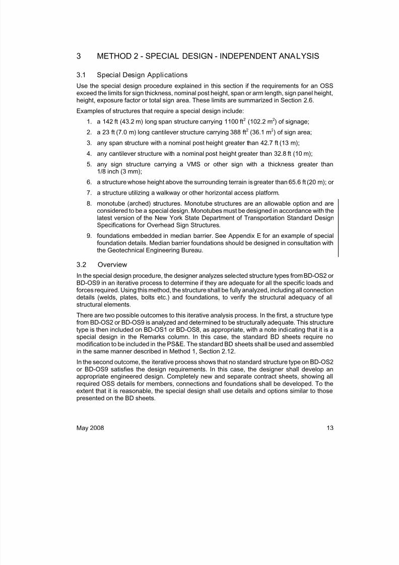
3.1 Special Design Applications
Use the special design procedure explained in this section if the requirements for an OSSexceed the limits for sign thickness, nominal post height, span or arm length, sign panel height,height, exposure factor or total sign area. These limits are summarized in Section 2.6.
Examples of structures that require a special design include:
1. a 142 ft (43.2 m) long span structure carrying 1100 ft2 (102.2 m2) of signage;
2. a 23 ft (7.0 m) long cantilever structure carrying 388 ft2 (36.1 m2) of sign area;
3. any span structure with a nominal post height greater than 42.7 ft (13 m);
4. any cantilever structure with a nominal post height greater than 32.8 ft (10 m);
5. any sign structure carrying a VMS or other sign with a thickness greater than
1/8 inch (3 mm);6. a structure whose height above the surrounding terrain is greater than 65.6 ft (20 m); or
7. a structure utilizing a walkway or other horizontal access platform.
8. monotube (arched) structures. Monotube structures are an allowable option and areconsidered to be a special design. Monotubes must be designed in accordance with thelatest version of the New York State Department of Transportation Standard DesignSpecifications for Overhead Sign Structures.
9. foundations embedded in median barrier. See Appendix E for an example of specialfoundation details. Median barrier foundations should be designed in consultation withthe Geotechnical Engineering Bureau.
3.2 Overview
In the special design procedure, the designer analyzes selected structure types from BD-OS2 orBD-OS9 in an iterative process to determine if they are adequate for all the specific loads andforces required. Using this method, the structure shall be fully analyzed, including all connectiondetails (welds, plates, bolts etc.) and foundations, to verify the structural adequacy of allstructural elements.
There are two possible outcomes to this iterative analysis process. In the first, a structure typefrom BD-OS2 or BD-OS9 is analyzed and determined to be structurally adequate. This structuretype is then included on BD-OS1 or BD-OS8, as appropriate, with a note indicating that it is aspecial design in the Remarks column. In this case, the standard BD sheets require nomodification to be included in the PS&E. The standard BD sheets shall be used and assembled
in the same manner described in Method 1, Section 2.12.
In the second outcome, the iterative process shows that no standard structure type on BD-OS2or BD-OS9 satisfies the design requirements. In this case, the designer shall develop anappropriate engineered design. Completely new and separate contract sheets, showing allrequired OSS details for members, connections and foundations shall be developed. To theextent that it is reasonable, the special design shall use details and options similar to thosepresented on the BD sheets.

8/18/2019 OSS Manual 2008 USC Update
http://slidepdf.com/reader/full/oss-manual-2008-usc-update 18/46
NYSDOT OSS Design Manual
14 May 2008
In accordance with the standard design specifications, sign structure designs follow allowablestress design (ASD) procedures. However, since recommendations for the design of hollowstructural sections (HSS) are not available in ASD, connections of pipe members shall followstrength design procedures, in accordance with the AISC Hollow Structural Sections
Connection Manual.
3.3 Special Design Procedure
3.3.1 Establish Basic Design Information
Follow the steps defined in Sections 2.1 to 2.5 of the Standard OSS Selection Procedure. Usingthe actual (or future, if governing) total sign area, nominal post height and span or arm length,select the structure type from the table on BD-OS2 or BD-OS9 which most closely satisfiesthese requirements. This structure will serve as the initial trial structure in the iterative designprocess.
3.3.2 Determine Loads
Determine the loads and forces to be applied to the trial structure selected in Section 3.3.1using the latest version of the NYSDOT Standard Design Specifications for OSS. For thespecial design, use the actual or projected future (whichever governs) sign panel sizes andlocations to be supported by the structure.
3.3.3 Iterative Analysis and Selection Process
Analyze the structure for the actual loads and forces determined in Sections 3.3.1 and 3.3.2.Investigate each aspect and detail of the structure for the appropriate loads and forces using thespecified design parameters identified in Section 3.3.2. In particular, investigate the connectionsto assure that they meet the requirements of the specific structure and its loads.
If the analysis determines that any part of the structure (including connection details) isinadequate, the next larger structure from the selection tables on BD-OS2 or BD-OS9 shall bechecked and the analysis process shall be repeated.
If the analysis determines that the structure initially selected is adequate, the next smallerstructure from the selection tables on BD-OS2 or BD-OS9 shall be investigated. The iterativeprocess shall continue until the most efficient standard structure type that satisfies all designrequirements is identified. (Note that the structure types listed on BD-OS2 and BD-OS9 use thedetails presented in the remaining BD sheets. In addition to the primary and secondarymembers, all connections and other members shall be analyzed to determine that the structure
is adequate for the design loads and forces established in Section 3.3.2.)
Enter the appropriate information for the selected structure type in the table on BD-OS1 orBD-OS8 following steps defined in Sections 2.8 to 2.12 of Method 1. Indicate in the Remarkscolumn of the Span Structure Table on BD-OS1 or the Cantilever Structure Table on BD-OS8that the structure is a special design. Also note which of the structure’s features fall outside thelimits of the normal standard design (sign area, nominal post height, sign height, sign thickness,and/or exposure factor). (Note: See Section 3.3.5 for VMS signs or other signs with thicknessgreater than 1/8 inch (3 mm).)
8/18/2019 OSS Manual 2008 USC Update
http://slidepdf.com/reader/full/oss-manual-2008-usc-update 19/46
May 2008 15
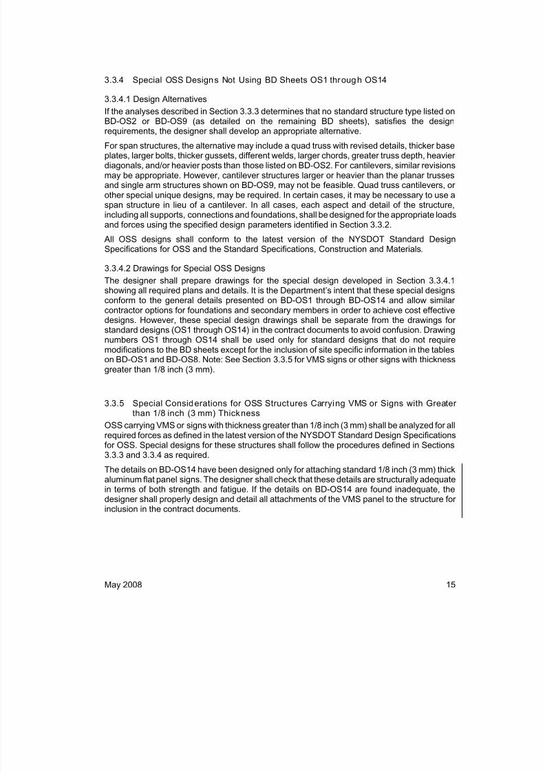
3.3.4 Special OSS Designs Not Using BD Sheets OS1 through OS14
3.3.4.1 Design Alternatives
If the analyses described in Section 3.3.3 determines that no standard structure type listed on
BD-OS2 or BD-OS9 (as detailed on the remaining BD sheets), satisfies the designrequirements, the designer shall develop an appropriate alternative.
For span structures, the alternative may include a quad truss with revised details, thicker baseplates, larger bolts, thicker gussets, different welds, larger chords, greater truss depth, heavierdiagonals, and/or heavier posts than those listed on BD-OS2. For cantilevers, similar revisionsmay be appropriate. However, cantilever structures larger or heavier than the planar trussesand single arm structures shown on BD-OS9, may not be feasible. Quad truss cantilevers, orother special unique designs, may be required. In certain cases, it may be necessary to use aspan structure in lieu of a cantilever. In all cases, each aspect and detail of the structure,including all supports, connections and foundations, shall be designed for the appropriate loadsand forces using the specified design parameters identified in Section 3.3.2.
All OSS designs shall conform to the latest version of the NYSDOT Standard DesignSpecifications for OSS and the Standard Specifications, Construction and Materials.
3.3.4.2 Drawings for Special OSS Designs
The designer shall prepare drawings for the special design developed in Section 3.3.4.1showing all required plans and details. It is the Department’s intent that these special designsconform to the general details presented on BD-OS1 through BD-OS14 and allow similarcontractor options for foundations and secondary members in order to achieve cost effectivedesigns. However, these special design drawings shall be separate from the drawings forstandard designs (OS1 through OS14) in the contract documents to avoid confusion. Drawingnumbers OS1 through OS14 shall be used only for standard designs that do not requiremodifications to the BD sheets except for the inclusion of site specific information in the tables
on BD-OS1 and BD-OS8. Note: See Section 3.3.5 for VMS signs or other signs with thicknessgreater than 1/8 inch (3 mm).
3.3.5 Special Considerations for OSS Structures Carrying VMS or Signs with Greaterthan 1/8 inch (3 mm) Thickness
OSS carrying VMS or signs with thickness greater than 1/8 inch (3 mm) shall be analyzed for allrequired forces as defined in the latest version of the NYSDOT Standard Design Specifications for OSS. Special designs for these structures shall follow the procedures defined in Sections3.3.3 and 3.3.4 as required.
The details on BD-OS14 have been designed only for attaching standard 1/8 inch (3 mm) thick
aluminum flat panel signs. The designer shall check that these details are structurally adequatein terms of both strength and fatigue. If the details on BD-OS14 are found inadequate, thedesigner shall properly design and detail all attachments of the VMS panel to the structure forinclusion in the contract documents.

8/18/2019 OSS Manual 2008 USC Update
http://slidepdf.com/reader/full/oss-manual-2008-usc-update 20/46
NYSDOT OSS Design Manual
16 May 2008
As noted in Section 1.3, cantilever structures shall not be used to support VMS unless there isno alternative, due to the unique fatigue loads induced as a result of the sign shape andeccentricity. When VMS must be supported on cantilever structures, the thickness of the VMSshall not exceed 15 inches (380 mm) and the load on the VMS, including its resulting out-of-
plane bending, shall be accounted for in the design process.For special designs completed under Section 3.3.3 for OSS supporting VMS, the designer shallmodify the Structure Table on BD-OS1 or BD-OS8 to include columns for not-to-exceeddimensions for height, length and thickness and not-to-exceed weights for the signs. This willensure that the signs installed in the contract correspond to the design assumptions.
For special designs completed under Section 3.3.4 that do not use BD-OS1 through BD-OS14,the designer shall also include not-to-exceed dimensions for height, length and thickness andnot-to-exceed weights for the signs in tables on the plans to insure that the signs installed in thecontract correspond to the design assumptions.
4 REFERENCES
1. New York State Department of Transportation Standard Design Specifications forOverhead Sign Structures, April 2007
2. Standard Specifications, Construction and Materials, New York State Department ofTransportation, Office of Engineering
3. Standard Specifications for Structural Supports for Highway Signs, Luminaires and
Traffic Signals, 4th Edition (2001) with 2002 , 2003 and 2006 Interims, published by AASHTO
4. NCHRP Report 412, Fatigue-Resistant Design of Cantilevered Signal, Sign andLight Supports, National Cooperative Highway Research Program, TransportationResearch Board, National Research Council, 1998

8/18/2019 OSS Manual 2008 USC Update
http://slidepdf.com/reader/full/oss-manual-2008-usc-update 21/46
NYSDOT OSS Design Manual Appendix A
May 2008 A1
APPENDIX A
MAJOR CHANGES FROM THE 1968 DESIGN MANUAL
AND THE 2000 INTERIM STEEL DESIGN (EI 00-035)
A.1 Standard Drawings/Standard Sheets /BD Sheets
Prior to the issuance of this Design Manual, span type OSS were selected from tablesdistributed in October 2000 by EI 00-035. Cantilever designs continued to use the 1968 DesignCriteria for Sign Structures. Details for both span and cantilever OSS were included onStandard Drawings and Standard Sheets. The Standard Drawings were inserted into thecontract plans and had blank tables that were filled in by the designer. The Standard Sheetscould generally be used as is and needed only to be referenced on the front sheet of the
contract plans to merit inclusion. With the BD sheets included in this manual, the designer willneed to fill in the Span Structure Table on BD-OS1 and/or the Cantilever Structure Table onBD-OS8 and insert into the contract package all sheets necessary to clearly specify themembers and details of the OSS.
A.2 Fatigue-Res istan t Detai ls for Cant ilever Struc tures
Connection details for cantilever structures have been substantially improved to increase fatigueresistance.
A.3 Refined Designs for Span St ructures
The dimensions of the quad-trusses used in the Interim Steel Design (EI 00-035) were notoptimized. The post spacings were variable and the details associated with base plates andsign attachments referenced existing Standard Sheets. The structures presented on the newBD sheets utilize only two basic quad-truss sizes and constant post spacing for each of thebasic truss sizes, allowing for uniform foundation configurations. The details for base plates andsign attachments have been modified to accommodate the new truss configurations. In addition,the fatigue resistance of the base plate welding has been improved.
A.4 Eliminat ion of Grout Cap
A significant problem identified during the sign structure inspection program was the
accumulation of water and debris inside post bases. Although drainage grooves had generallybeen provided, they were not functioning as designed and did not allow the post bases to drainfreely. To address this problem, the new design has eliminated the grout cap so that the open-based post is supported directly on the anchor bolt leveling nuts. Protective screening materialis used to prevent birds or small animals from nesting inside the posts.

8/18/2019 OSS Manual 2008 USC Update
http://slidepdf.com/reader/full/oss-manual-2008-usc-update 22/46
NYSDOT OSS Design Manual Appendix A
A2 May 2008
A.5 Pedestal Height
The previous standard called for the pedestal to project above the finished grade by 8 inches(200 mm) at the centerline of the pedestal. This relatively small projection left very littleclearance above the top of the ground at the edge of the pedestal. As a result, during theinspection program, many of the base plates and anchor bolts at existing sign structurefoundations were found to be buried or surrounded by vegetation preventing drainage andaccelerating deterioration. The new design increases the height of the pedestal above grade to24 inches (600 mm) at the centerline of the pedestal, which is expected to reduce or eliminatethe problem.
A.6 Handhole Location
The handhole for span structures was located on the back of the post, away from traffic. Thislocation prevents the intrusion of deicing salts into the post base in the event that the handholecover is missing or improperly sealed. However, the handhole for cantilever structures waslocated on the front face, or traffic side, of the cantilever post, making the post susceptible tosalt spray. The original intent of the front face location is believed to have been an attempt toplace the opening in a zone of compressive stress. The new design provides sufficientreinforcing at the post opening in order to allow the hand hole to be placed opposite traffic for allposts, offering additional protection against salt spray.
A.7 Truss Connections
The previous standard in use prior to the issuance of the Interim Steel Design called for steelposts and aluminum trusses at span structures and steel posts and either steel or aluminumarms at cantilever structures. In these structures, generally the diagonal to chord and strut to
chord connections were made using tube to tube welds. Tube to tube welds have acomparatively low resistance to fatigue. The Interim Steel Design called for steel members forall sign support structures with split tube gusset plate connections and eliminated aluminum asan option. The gusset plate split tube connections were also an improvement since they aremuch more fatigue resistant than the tube to tube connections. However, the gusset plateconnections do not allow as much flexibility in the location of sign attachments as the tube-to-tube connections. Therefore, closer coordination is required between the sign structurefabricator and the sign panel manufacturer to ensure that the sign panel attachments can beproperly installed on the structure.

8/18/2019 OSS Manual 2008 USC Update
http://slidepdf.com/reader/full/oss-manual-2008-usc-update 23/46
NYSDOT OSS Design Manual Appendix B
May 2008 B1
APPENDIX BDESIGN ASSUMPTIONS USED FOR STANDARD OSS
ON BD-OS1 THROUGH BD-OS14
B.1 General
The standard OSS shown on BD-OS1 through BD-OS14 are designed using the NYSDOTStandard Design Specifications for OSS, April 2007 and the additional design assumptions andclarifications contained in this appendix.
B.2 Loads
B.2.1 Dead Load
Steel: 490 pcf (7850 kg/m3)
Sign panels, including stiffeners and attachments: 7 psf (35 kg/m2)
Concrete in foundation design: 150 pcf (2400 kg/m3)
Soil in foundation design: 120 pcf (1920 kg/m3)
Members are assumed to extend from joint to joint, with no deduction for intersecting members.
B.2.2 Live Load
No live load has been used in the design of the standard structures. No walkways or serviceplatforms are included on the standard structures.
B.2.3 Ice and Snow Loads
Ice load has been applied to the standard structures in accordance with the NYSDOT StandardDesign Specifications for OSS, April 2007. No snow load has been applied.
8/18/2019 OSS Manual 2008 USC Update
http://slidepdf.com/reader/full/oss-manual-2008-usc-update 24/46
NYSDOT OSS Design Manual Appendix B
B2 May 2008
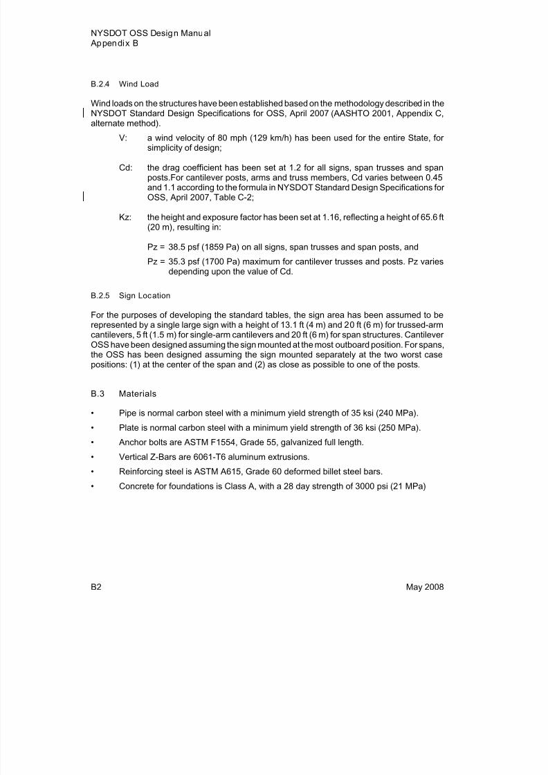
B.2.4 Wind Load
Wind loads on the structures have been established based on the methodology described in theNYSDOT Standard Design Specifications for OSS, April 2007 (AASHTO 2001, Appendix C,alternate method).
V: a wind velocity of 80 mph (129 km/h) has been used for the entire State, forsimplicity of design;
Cd: the drag coefficient has been set at 1.2 for all signs, span trusses and spanposts.For cantilever posts, arms and truss members, Cd varies between 0.45and 1.1 according to the formula in NYSDOT Standard Design Specifications forOSS, April 2007, Table C-2;
Kz: the height and exposure factor has been set at 1.16, reflecting a height of 65.6 ft(20 m), resulting in:
Pz = 38.5 psf (1859 Pa) on all signs, span trusses and span posts, and
Pz = 35.3 psf (1700 Pa) maximum for cantilever trusses and posts. Pz variesdepending upon the value of Cd.
B.2.5 Sign Location
For the purposes of developing the standard tables, the sign area has been assumed to berepresented by a single large sign with a height of 13.1 ft (4 m) and 20 ft (6 m) for trussed-armcantilevers, 5 ft (1.5 m) for single-arm cantilevers and 20 ft (6 m) for span structures. CantileverOSS have been designed assuming the sign mounted at the most outboard position. For spans,
the OSS has been designed assuming the sign mounted separately at the two worst casepositions: (1) at the center of the span and (2) as close as possible to one of the posts.
B.3 Materials
• Pipe is normal carbon steel with a minimum yield strength of 35 ksi (240 MPa).
• Plate is normal carbon steel with a minimum yield strength of 36 ksi (250 MPa).
• Anchor bolts are ASTM F1554, Grade 55, galvanized full length.
• Vertical Z-Bars are 6061-T6 aluminum extrusions.
• Reinforcing steel is ASTM A615, Grade 60 deformed billet steel bars.
• Concrete for foundations is Class A, with a 28 day strength of 3000 psi (21 MPa)
8/18/2019 OSS Manual 2008 USC Update
http://slidepdf.com/reader/full/oss-manual-2008-usc-update 25/46
NYSDOT OSS Design Manual Appendix B
May 2008 B3
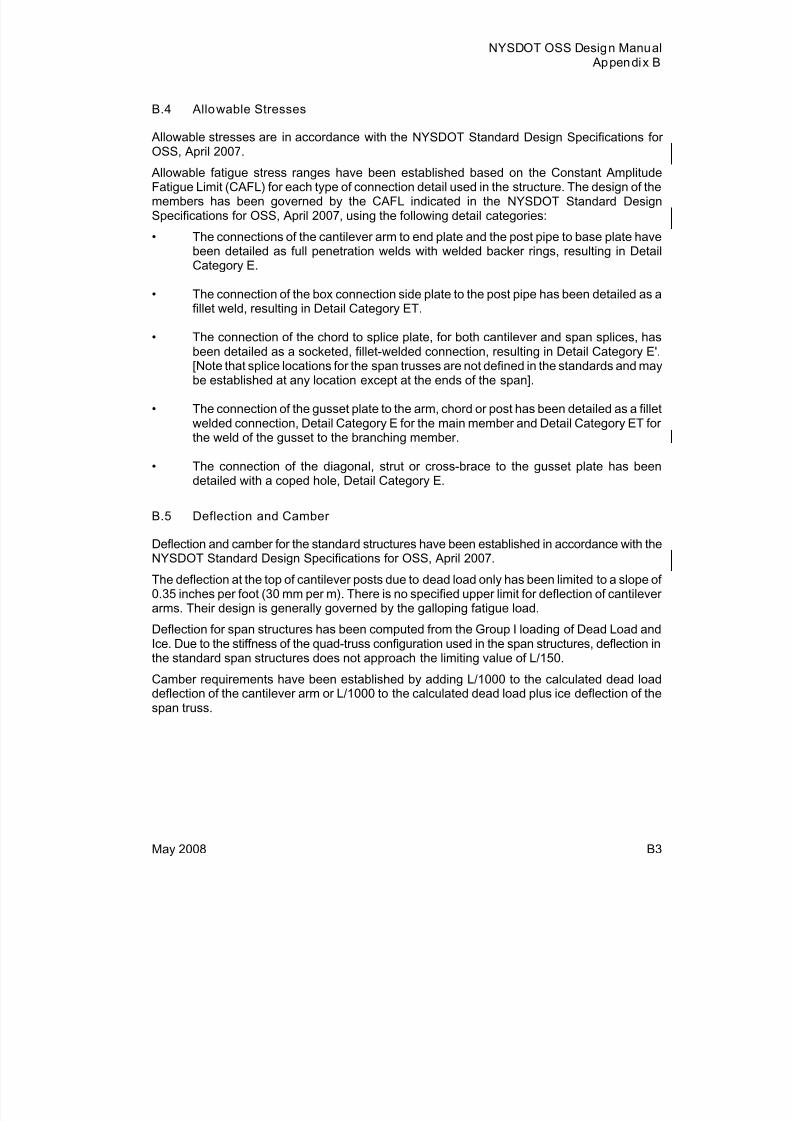
B.4 Allowable Stresses
Allowable stresses are in accordance with the NYSDOT Standard Design Specifications forOSS, April 2007.
Allowable fatigue stress ranges have been established based on the Constant AmplitudeFatigue Limit (CAFL) for each type of connection detail used in the structure. The design of themembers has been governed by the CAFL indicated in the NYSDOT Standard DesignSpecifications for OSS, April 2007, using the following detail categories:
• The connections of the cantilever arm to end plate and the post pipe to base plate havebeen detailed as full penetration welds with welded backer rings, resulting in DetailCategory E.
• The connection of the box connection side plate to the post pipe has been detailed as afillet weld, resulting in Detail Category ET.
• The connection of the chord to splice plate, for both cantilever and span splices, hasbeen detailed as a socketed, fillet-welded connection, resulting in Detail Category E'.[Note that splice locations for the span trusses are not defined in the standards and maybe established at any location except at the ends of the span].
• The connection of the gusset plate to the arm, chord or post has been detailed as a filletwelded connection, Detail Category E for the main member and Detail Category ET forthe weld of the gusset to the branching member.
• The connection of the diagonal, strut or cross-brace to the gusset plate has beendetailed with a coped hole, Detail Category E.
B.5 Deflection and Camber
Deflection and camber for the standard structures have been established in accordance with theNYSDOT Standard Design Specifications for OSS, April 2007.
The deflection at the top of cantilever posts due to dead load only has been limited to a slope of0.35 inches per foot (30 mm per m). There is no specified upper limit for deflection of cantileverarms. Their design is generally governed by the galloping fatigue load.
Deflection for span structures has been computed from the Group I loading of Dead Load andIce. Due to the stiffness of the quad-truss configuration used in the span structures, deflection inthe standard span structures does not approach the limiting value of L/150.
Camber requirements have been established by adding L/1000 to the calculated dead load
deflection of the cantilever arm or L/1000 to the calculated dead load plus ice deflection of thespan truss.

8/18/2019 OSS Manual 2008 USC Update
http://slidepdf.com/reader/full/oss-manual-2008-usc-update 26/46
NYSDOT OSS Design Manual Appendix B
B4 May 2008
B.6 Structural Configurations
In preparation for the development of this manual, a number of structural configurations wereinvestigated. All configurations utilized round pipe for the primary structural elements, since thecircular surface attracts the least wind load. Constant diameter pipe was used to simplifyconnections.
B.7 Connections
The model used in the analysis of the trussed arm cantilever structures assumes that 50% ofthe primary longitudinal wind force is transmitted to each arm.
The model used in the analysis of the span structures assumes that welded connections arerigid (fixed) in the plane of the gusset plate and flexible (pinned) in the direction perpendicular tothe gusset plate. Bolted connections are assumed to be flexible (pinned) in both planes.
In accordance with the NYSDOT Standard Design Specifications for OSS, April 2007, sign
structure designs follow allowable stress design (ASD) procedures. However, sincerecommendations for the design of hollow structural sections (HSS) are not available in ASD,connections of pipe members follow strength design procedures, in accordance with the AISCHollow Structural Sections Connection Manual.
B.8 Foundations
Two types of foundations have been presented on the BD sheets, formed rectangular footingsand cast-in-place drilled shafts.
The parameters used in the development of the foundation designs include:
1. Allowable Soil Pressure: 2 tsf (200 kPa)2. Allowable Rock Pressure: 5 tsf (500 kPa)
3. Soil Friction Angle: 28 degrees
4. Coefficient of Sliding Friction: 0.50
The standard foundations assume one of two possible substrates, either sound rock or soil freeof soft clay and organic deposits.
Groundwater is assumed to be below the bottom of the foundation.
For the purposes of foundation design, the allowable soil and rock stresses have not beenincreased by the percentages of allowable stress listed in Table 3-1 of the NYSDOT Standard
Design Specifications for OSS, April 2007. Conversely, the applied loads have not beendecreased by those percentages.

8/18/2019 OSS Manual 2008 USC Update
http://slidepdf.com/reader/full/oss-manual-2008-usc-update 27/46
NYSDOT OSS Design Manual Appendix B
May 2008 B5
The depths of the footing foundations shown on BD-OS3 and BD-OS10 have been establishedusing the maximum finished transverse slope of 2 horizontal to 1 vertical and a minimum depthto bottom of footing of 4 feet (1.25 meters), perpendicular to the slope, at the low edge of thefooting. The load of the average depth of soil overburden at the centerline footing has been
included in the calculation of the overturning resistance.The resultant substrate pressures have been adjusted to reflect the absence of tension betweenthe footings and their substrates.
A minimum overturning factor of safety of 1.5 has been used for footings on either soil or rock. Aminimum sliding factor of safety of 2.0 has been used for footings on either soil or rock.

8/18/2019 OSS Manual 2008 USC Update
http://slidepdf.com/reader/full/oss-manual-2008-usc-update 28/46

8/18/2019 OSS Manual 2008 USC Update
http://slidepdf.com/reader/full/oss-manual-2008-usc-update 29/46
NYSDOT OSS Design Manual Appendix C
May 2008 C1
APPENDIX CISSUES AND OPTIONS EVALUATED DURING THE DEVELOPMENT
OF THE STANDARD OSS DESIGNS
C.1 General
Many options and issues were investigated during the development of the standard designspresented on BD sheets BD-OS1 through BD-OS14. The most appropriate option was identifiedbased on several criteria: ease of selecting the applicable structure; minimization of futurestructure replacement and cost effectiveness of structure construction.
In order to simplify the structure selection process, it was decided to utilize tables of standardstructures based on only three parameters: the span length (or arm length, for cantilevers), the
area of sign panel carried and the height of the posts. The height of the posts for cantileverswas set at 32.8 ft (10 m) maximum, since their height above grade does not vary as much asthe height of posts required for span structures.
The variations in length between standard structures (16.4 ft (5 m) increments for the spanstructures and 3.3 ft (1 m) increments for the cantilever structures) were selected in an effort tominimize the number of different configurations and to allow for standardization of thefabrication process, where possible.
The sign areas selected for the standard structures were intended to give the design engineer awide range of areas to choose from while also including the maximum expected amount ofsignage on each span or arm length. For span structures, the sign area of 322.9 (30 m2)represents the average amount of signage that structures will normally be expected to carry.
The other two span structure sign area options, 545.8 ft2
(60 m2
) and 968.8 ft2
(90 m2
), areexpected to be used less frequently.
The nominal post height increments for the standard span structures were established torepresent typical structure heights. The 29.5 ft (9 m) height can generally be used at areaswhere the roadway cross section is minimally superelevated and where the posts are fairlyclose to the edge of shoulder and not placed on a steep fill slope. The other nominal post heightincrements are intended to cover by far the great majority of normal span structure heights inthe State.
Analyses were performed to compare the costs of various alternative designs. In addition,analyses were performed to evaluate the cost impacts of simplifying assumptions used for thestandard designs included on BD-OS2 and BD-OS8. These cost studies included:
• Comparing trusses of various depths
• Comparing aluminum and galvanized steel structures
• Tri-chord trusses vs. quad trusses, monotubes and planar trusses
• Full penetration welds at specific locations vs. fillet welds
• Analyzing the cost impacts of simplifying assumptions used for span length, signlocations, sign height, sign area, and exposure factor.
8/18/2019 OSS Manual 2008 USC Update
http://slidepdf.com/reader/full/oss-manual-2008-usc-update 30/46
NYSDOT OSS Design Manual Appendix C
C2 May 2008
Other issues investigated during the development of this design manual included:
C Structure materials
C Structure configurations
C Foundation typesC Anchor bolts
C Post spacing
C Post height
C Exposure factor
C Support beam at span structure dual posts
C Erection sequence for overhead span truss
C Quad truss size
C Fatigue-resistant weld details
C Welded vs bolted connections
C Single-sided connections
C Maximum pipe sizes
C Stiffeners at splice plates and base plates
C Diagonal and strut options
C Out of plane bending
C Sign connection interference issues
C Two post foundations for spans
Some of the background on the decisions made concerning these issues is presented below.
C.2 Structure Materials
The two most common materials in use for sign structures are steel and aluminum. Othermaterials, such as Fiber Reinforced Polymers, have been suggested; however their use isconsidered experimental at this time. Both NCHRP Report 412 and AASHTO (4th Edition, 2001Standard Specifications for Structural Supports for Highway Signs, Luminaires and TrafficSignals) indicate that the Constant-Amplitude Fatigue Thresholds for aluminum are quite lowcompared to the thresholds for steel. As a result, steel is the material that has been selected foruse in the standard sign structures. Although weathering steel has some advantages and couldbe utilized in some circumstances, it is not appropriate statewide and therefore has not beenspecified in the standard structures. Galvanization is considered to be a long-term, low
maintenance method of protecting steel from corrosion; therefore, galvanized steel has beenspecified.
The types of acceptable pipe steels listed in the specifications were intended to provide ductile,weldable material with a minimum yield strength of 35 ksi (240 MPa). The pipe materials werealso selected to allow the greatest possible availability given the large range of pipe sizesspecified in the standard tables.

8/18/2019 OSS Manual 2008 USC Update
http://slidepdf.com/reader/full/oss-manual-2008-usc-update 31/46
NYSDOT OSS Design Manual Appendix C
May 2008 C3
Gusset plates, splice plates and base plates used in the sign structure construction are intendedto be compatible with the pipe materials, ductile and weldable, with a minimum yield strength of36 ksi (250 MPa) (conforming to ASTM A36). Steel used in sign structure elements is subject toCharpy requirements as per the Sign Structures specification to ensure ductility.
C.3 Structure Configurations
Span Structures. For the span structures, a number of structural configurations wereinvestigated in addition to the quad-truss configuration presented in the standard table: singlemembers spanning between single posts, planar trusses spanning between single posts,monotubes with and without frame action and tri-trusses similar to those being used throughoutthe State for the past thirty years. The single members, planar trusses and monotubeconfigurations were not included as standards because their applicability was limited to fairlyshort spans and/or allowed signage areas. (Monotubes are allowed as a special design optionas per 3.1.) The tri-trusses were not included as standards because they are less able to carrytorsional loads due to the eccentricity of signs, platforms, lighting and other attachments that are
commonly placed on sign structures, as well as the torsional loads due to Variable MessageSigns. The quad-truss configuration was deemed the most versatile, accommodating all spanlengths with good torsional rigidity.
In addition, for simplicity, it was desirable to present a single structure configuration that couldmeet the strength and detailing requirements of the full range of expected sign structure spanlengths and sign areas at reasonable cost. As a result, the four chord quad-truss was selectedfor the standard tables.
Cantilever Structures. There were also several variations on the configuration of the cantileverstructure considered, in addition to the single arm and trussed dual arm configurations detailedon the BD sheets, including the curved monotube and the untrussed dual arm.
The curved monotube can be used for only a limited range of cantilever arm lengths. It involves
different details than those required for the standard span structures (implying inefficiencies infabrication) and it has the same limitation on sign height mentioned above for the spanmonotube.
The untrussed dual arm requires either that the connections and vertical stiffeners of the signpanel act to transmit vertical load between the two arms or that the full vertical load be carriedby each arm acting independently. Since the design of the cantilever arms for many arm lengthsis governed by the galloping load, requiring that the full vertical load be carried by a single armwould be very inefficient. Redesign and redetailing of the sign panel connections and verticalstiffeners to transmit the vertical loads to ensure that the loads are shared equally by both armswould introduce additional complexity into the sign elements and require a different approach tosign panel design. Therefore, only the trussed dual arm cantilever has been presented on the
BD sheets.
C.4 Foundation Types
Prior to the issuance of this manual and the associated BD sheets, the only foundation typespecified for dual post span structure foundations was a formed, rectangular footing. No optionwas allowed. Presenting an option for a drilled shaft will allow for simplification and economy ofconstruction.

8/18/2019 OSS Manual 2008 USC Update
http://slidepdf.com/reader/full/oss-manual-2008-usc-update 32/46
NYSDOT OSS Design Manual Appendix C
C4 May 2008
C.5 Anchor Bolts
The field inspections have also noted cases where anchor bolt nuts were loose. In order toensure that these nuts do not loosen, the new details require double nuts, rather than lock nuts.
Also, to provide an additional factor of safety and redundancy, all post bases have beendetailed with a minimum of six anchor bolts.
Misalignment encountered when post base plates are mounted on anchor bolts can result fromseveral possible sources. Despite all care, the anchor bolt template may shift during concreteplacement; the template may be slightly loose or the base plate could be slightly rotated from itsintended orientation. Exaggerating any minor misalignment, is the increase in the number ofanchor bolts from four to at least six. As a result, the size of the holes in the base plate hasbeen increased to allow more space for such minor misalignments of the cast-in-place anchorbolts.
C.6 Post Spacing
In span structures, two new post spacings were established in order to limit the number of sizesfor the spacing of the cast-in-place pedestals while accommodating all the various quad-trussconfigurations presented in the standard selection tables. The simplicity of only two postspacings should allow consistency in the construction of the sign structure foundations, resultingin a higher level of accuracy and quality in foundation placement.
C.7 Post Height
If the sign height is greater than the truss chord spacing, which it generally is, the verticalclearance and post height will be governed by the location of the sign. For simplicity ofinstallation of signs, each sign or sign assembly is intended to be centered on the truss. If there
is a supplementary panel associated with a main panel, or multiple panels arranged vertically,refer to BD-OS14 for criteria regarding locating the sign vertical centroid in relation to the trusscentroid.
The post height used in the standard cantilever structures is 32.8 ft (10 m) from the bottom ofthe base plate to the centerline of the trussed arms (and sign panel). The 32.8 ft (10 m) height isexpected to be sufficient for nearly all cantilever structures constructed in the State.
The three post heights used in the standard span structures, 29.5 ft (9 m), 36.1 ft (11 m) and42.7 ft (13 m), are intended to give a sufficient range to accommodate essentially all spanstructures in the State.
C.8 Exposure Factor
An exposure factor of Kz = 1.16 has been used for the standard designs. This exposure factorrepresents a structure height above surrounding terrain of 65.6 ft (20 m). This height wasselected because it is expected to include the overwhelming majority of sign structuresthroughout the State. It is expected that only structures on high bridges or in particularly unusuallocations will have exposure factors exceeding the selected value, requiring special designs.
8/18/2019 OSS Manual 2008 USC Update
http://slidepdf.com/reader/full/oss-manual-2008-usc-update 33/46
NYSDOT OSS Design Manual Appendix C
May 2008 C5
C.9 Support Beam at Span Structure Dual Posts
During the design of the standard structures, the options available for the detail of the supportfor the span structure quad-truss at the dual posts included a bracket-type support or a supportbeam. However, the available space between the face of the chord and the face of the postvaried widely, as did the vertical load imposed by the chords under combined dead and windloads. In order to present only two post spacings, the support beam option was selected. Thedetail at the connection to the post has been designed to transmit the forces resulting from theanalysis, including dead load, wind load and thermal load.
The chords have been detailed with a half-height saddle, and double U-bolts at each support.The 180 degree saddle allows the connection to transmit both vertical and horizontal load fromthe chord into the horizontal support beam. The surface of the saddle has not been machined,since it is expected that the shape of the chord will conform to the shape of the saddle underload.
C.10 Erection Sequence for Overhead Span Truss
The OSS support system has been designed for all dead load of the truss to be carried by thelower support beam. While the trusses may be transported with the upper saddles, U-bolts andsupport beams attached, it is expected that the lower support beam will be fully connected tothe post assembly prior to erecting the overhead span truss. The truss will then be lowered ontothe lower support beams at each end with the saddles in place, the bottom chords will beshimmed and leveled as necessary and the U-bolts will be installed at the bottom chords. Thetop support beam will then be installed and connected to the posts at each end, adjusted forsnug fit of the top chord saddles and the U-bolts installed at the top chords. There is notexpected to be any dead load in the top support beam.
C.11 Quad Truss Size
The two quad truss chord spacings presented for the span structures, 6.5 ft (2.0 m) and 8.2 ft(2.5 m), are intended to provide cost-effective trusses for the full range of expected signstructure span lengths and sign areas. The most significant constraint for the truss sizes is thesize of available galvanizing tanks. It is not expected that either the 6.5 ft (2.0 m) truss or the8.2 ft (2.5 m) truss fully fabricated will fit into existing available galvanizing tanks, therefore,bolted top and bottom diagonals and struts and cross braces have been presented, so that thefront and back welded planar trusses can be galvanized separately and assembly performedafter galvanizing.
While a smaller truss chord spacing could have been specified, it was judged to be more
beneficial to present only two chord spacings in order to limit the variations in fabricationprocesses. In addition, the smaller chord spacing investigated, 5 ft (1.5 m), provided only alimited range of cost-effective application and contained significantly more welded connectionsper unit of length than the larger trusses.

8/18/2019 OSS Manual 2008 USC Update
http://slidepdf.com/reader/full/oss-manual-2008-usc-update 34/46
NYSDOT OSS Design Manual Appendix C
C6 May 2008
C.12 Fatigue-Resistant Weld Details
One of the primary reasons for revising the sign structure design presented in the 1968NYSDOT sign structure design manual was the introduction of more fatigue-resistant welddetails. The tube-to-tube welding details presented in the earlier documents for the diagonal andstrut connections to the chords and posts result in very low Constant Amplitude Fatigue Limits(CAFL), category ET, and are primarily applicable to aluminum members, which are easier toshape for the complex connection configurations. The revised design replaces the tube-to-tubeconnections with split-tube gusset plate connections, intended to increase fatigue resistance bysimplifying the connection, making it more flexible and increasing the overall length of the weld.The weld of the gusset plate to the chord has been detailed as an all around weld, to avoid thequality issues associated with starting and stopping the welding process and to provide a seal atthe ends of the gusset plates. While the gusset-to-chord weld continues to be fatigue categoryET, it is expected that the simplified connection will increase the quality of the connection. Theradiused transition at the ends of the gusset, as detailed in Example 15 (Figure 11-1(e) of
AASHTO, 4th Edition, 2001 Standard Specifications for Structural Supports for Highway Signs,Luminaires and Traffic Signals), were considered. However, the fatigue stresses in the gussetplates were within the allowables for category ET and therefore the additional complexity of theshaped gusset and ground welds was not justified.
In addition to the revision of the diagonal and strut connections, the connections at the posts tobase plates and cantilever arms to end plates have also been revised. These connections wereoriginally detailed as socketed fillet welds, which have a relatively low CAFL detail category ofE'. This low CAFL significantly affected the design of the posts and arms. As a result, thesocketed, fillet welded details were replaced with full penetration welds, with fillet welded backerrings, resulting in detail category E and nearly doubling the fatigue resistance in the connection.
The splice locations in the span and cantilever structure trusses use socketed welds with detailcategory E'. It was determined that, at these locations, member sizes were not impacted by thereduced allowable fatigue stress range and, as a result, it would not be cost effective to use the
more complex full penetration welds. Therefore, the splice plate connections continue to use thesocketed, fillet welded detail.
C.13 Welded vs Bolted Connections
As mentioned above, the span quad-trusses and some of the cantilever trusses are too large tobe hot dipped galvanized fully assembled. As a result, bolted connections have been shown inthe top and bottom planes, as well as at the internal cross braces. The front and back trussesare shown fully welded in order to preserve the camber in those elements throughout thefabrication process.
In the cantilever trussed arms, since the spacing of the arms varies, those elements may alsoincrease to the point that fully-assembled galvanization becomes a problem. Therefore theoption is available to either weld or bolt the cantilever truss elements. An exception is made atthe bay where a splice is introduced into the cantilever chords. In that bay, a bolted diagonalshall be provided, to be assembled, along with the splice, after galvanizing.
Oversize holes have been allowed in certain quad truss bolted connection elements due to theadditional complexity of the multi-plane structure and the tolerances involved in its fabrication.Since the cantilever structure is within a single plane, no oversize holes have been allowed inthat structure’s bolted configuration.

8/18/2019 OSS Manual 2008 USC Update
http://slidepdf.com/reader/full/oss-manual-2008-usc-update 35/46
NYSDOT OSS Design Manual Appendix C
May 2008 C7
C.14 Single-Sided Connections
Single-sided connections were investigated at the span truss supports and at split tube boltedconnections. Due to the magnitude of the axial loads carried by these members, the single-sided connections introduced significant eccentric loads into the structural elements, increasingthe sizes of both primary and secondary members. Symmetric, double-sided connections arepresented on the BD sheets, except at the post diagonals and struts, where heavy single anglesare an option.
C.15 Maximum Pipe Sizes
The post pipe sizes indicated in the standard cantilever designs are larger than those previouslypresented in Department standards. These larger pipe sizes generally require special handlingduring fabrication and additional attention during detailing due to their higher diameter tothickness ratios. However, during the development of the standard cantilever selection tables, itwas determined that limited cantilever arm length and sign area combinations would beavailable if the previous maximum pipe size (NPS 20 XS) were not exceeded. Therefore, pipesizes up to NPS 36 were used in the design of cantilever posts. Since the larger pipe diametersare less common, only NPS 24, 26, 30 and 36 have been included in the standard selectiontables.
C.16 Stiffeners at Splice Plates and Base Plates
The splice plate and base plate connections have been detailed and sized to eliminate the needfor stiffeners between the posts or chords and their connection plates. These details areintended to keep the area clean of any possible trapped debris and allow the connections to beself-cleaning. In addition, by eliminating stiffeners, welding has been reduced with the intention
that the remaining welding can be closely quality controlled, resulting in higher quality welding atthese critical areas.
C.17 Diagonal and Strut Options
The diagonal and strut options presented for the span structures on the BD sheets include: Splittube, single angle or double angle elements. Split tube elements have been allowed in anydiagonals or struts, in either the trussed posts or the overhead span truss.
Angle options have only been allowed in specific locations not exposed to primary wind loads,since curved surfaces are more efficient than flat surfaces when exposed to wind.
The single angle diagonal and strut have only been allowed in the dual post assembly for thespan truss, since their weight and exposed area precludes the use of these elements in theoverhead span truss itself. The single angle connection is an asymmetrical, one sidedconnection. The heavy angle shown in the selection table has been designed for the eccentricityresulting from the one-sided connection.
Double angles have been allowed at both the trussed posts and the horizontal elements andcross braces of the overhead span trusses.
8/18/2019 OSS Manual 2008 USC Update
http://slidepdf.com/reader/full/oss-manual-2008-usc-update 36/46
NYSDOT OSS Design Manual Appendix C
C8 May 2008
C.18 Out-of -Plane Bending
The trussed cantilever arms are subject to out-of-plane bending primarily when the wind on theface of the panel is not uniform. With the longer cantilever arms, the differential deflectionbetween the two arms can be significant under non-uniform wind load. Inspections of existinggusset-plated connections have shown that the welds of some of these connections havecracked. It has been postulated that most of these cracked welds have resulted from out-of-plane bending. During the design of the standard cantilever structures, the flexibility of thegusset plate connection was investigated. As a result, the distance from the end of the split tubeand the face of the arm was increased from ½ inch (12 mm) to 2 inch (50 mm), considerablyincreasing the flexibility of the connection and resulting in more uniform stress in the gussetplate.
C.19 Sign Connection Interference
Since the new standard sign structures utilize gusset plate connections rather than the previoustube-to-tube connections, there was a concern that there could be inadequate space to mountthe sign panels. The various configurations of truss chord spacing, including the minimum armspacing of 5 ft (1.5 m) at the cantilever trussed arms, were investigated to determine whetherthere would be enough space available for mounting the sign connection U-bolts and verticalzee bars. The most critical situation was at the span structure splice locations, where the U-bolts need to be mounted on either side of the end strut/diagonal connections at the splice.Since this could present difficulties in the required arrangement of sign connections, a note hasbeen added to the sign attachment BD sheet alerting the contractor to the possibility ofinterference, asking the contractor to coordinate the spacing of the vertical zee bars and theavailable locations for attachment on the truss and allowing the contractor to shift the sign asmall distance if the interference cannot be resolved by respacing the zee-bars.
C.20 Two Post Foundations for Spans
Two post foundations were selected for all spans due to the increased redundancy whencompared to single post foundations.
C.21 Wire Inlets
Wire Inlets have been provided to accommodate electrical wiring for lighted signs. They are notrequired when sign lighting is not provided. In order to protect the inlets from damage duringtransport and erection, galvanized caps have been specified.
The design of the chord members included an investigation of the impact of the reduction insection due to the wire inlets. While most of the chords were unaffected by the reduction, twotruss chords, the 49.2 ft (15 m) span with 645.8 ft2 (60 m2) of sign and the 131.2 ft (40 m) spanwith 322.9 ft2 (30 m2) of sign, required a larger chord due to the introduction of the wire inlets.

8/18/2019 OSS Manual 2008 USC Update
http://slidepdf.com/reader/full/oss-manual-2008-usc-update 37/46
NYSDOT OSS Design Manual Appendix D
May 2008 D1
APPENDIX DFOUNDATION LOADS AT STANDARD OSS
D.1 Introduction
The foundation loads presented in the tables below are the governing loads resulting from theanalyses of the standard structures. These loads result from the application of dead load, wind,ice and thermal variations on the OSS. While many loads have been applied to the structuresduring the investigations in order to evaluate maximum or fatigue stresses in the individualstructural members, the loads presented here are those that govern the foundation design.They are presented here to assist the Department in evaluating structures which fall outside theparameters defining standard OSS and those encountering unique site conditions.
For all loads presented in this appendix, the longitudinal direction is perpendicular to the sign,parallel to traffic. The transverse direction is parallel to the sign, perpendicular to traffic.
D.2 Span Structures
The span structure loads are effective at the bottom of base plate at the center of thefoundation, midway between the two pedestals or shafts that comprise the foundation. TheFoundation Type categories have been established based on groupings of maximumlongitudinal moment. These foundation loads represent the loads resulting from the family ofOSS included in each of the Foundation Type categories. The categories include from one to 15standard structures.
Maximum and minimum dead loads are presented because minimum vertical load is a criticalloading in some cases. The minimum dead load is that of the lightest structure in the next-smaller category (or, in the case of the 49.2 ft (15 m) span, two-thirds of the weight of thelightest structure in the 49.2 ft (15 m) span category). For instance, since a structure in the65.6 ft (20 m) span category could actually be 49.5 ft (15.1 m) long, the minimum weight listedhere would be that of the lightest standard 49.2 ft (15 m) span structure.
The Standard Span Structures table on BD-OS2 indicates which structures are included in eachof the foundation type categories. Since the foundation type categories were established basedon the maximum moment due to wind, it may be noted that the other, associated loads in eachcategory do not necessarily increase consistently from Type S-A through Type S-K. Forinstance, the maximum dead load for Type S-G is greater than that of Type S-H and Type S-Jbecause Type S-G contains a 213.3 ft (65 m) structure with 968.8 ft2 (90 m2) of sign area and a
29.5 ft (9 m) high post. Although the dead load of the S65-90-9 structure in Type S-G is greater,the maximum moment is less than that of the S65-60-13 structure that governs Type S-H andthe S60-90-13 structure that governs Type S-J.
Although the transverse moment and transverse shear are essentially split between the twopedestals, with each pedestal carrying approximately 50% of the force listed in this table, thelongitudinal shear is not evenly distributed between the two pedestals. For design purposes, theactual longitudinal shear at an individual pedestal has been taken to be 90% of the totalmaximum longitudinal shear listed in the table below.

8/18/2019 OSS Manual 2008 USC Update
http://slidepdf.com/reader/full/oss-manual-2008-usc-update 38/46
NYSDOT OSS Design Manual Appendix E
D2 May 2008
SPAN STRUCTURE FOUNDATION LOADS
FOUNDATIONTYPE
MAXIMUMLONGITUDINAL
MOMENTk-ft (kN-m)
MAXIMUMVERTICAL
DEAD LOADkips (kN)
MINIMUMVERTICAL
DEAD LOADkips (kN)
MAXIMUMTRANSVERSE MOMENTk-ft (kN-m)
MAXIMUMLONGITUDIN AL SHEAR
kips (kN)
MAXIMUMTRANSVERSE
SHEARkips (kN)
S-A 445 (600) 13.3 (59) 4.5 (20) 59 (80) 15.5 (69) 3.8 (17)
17.1 (76) 5.2 (23) 88 (119) 18.9 (84) 4.7 (21)
12.4 (55) 7.0 (31) 84 (113) 15.5 (69) 3.8 (17)S-B 590 (800)
36.2 (161) 12.1 (54) 101 (137) 20.5 (91) 6.5 (29)
18.9 (84) 6.1 (27) 127 (171) 26.8 (119) 6.7 (30)
19.3 (86) 6.7 (30) 114 (154) 18.9 (84) 4.7 (21)S-C 740 (1000)
38.7 (172) 12.1 54) 122 (165) 22.0 (98) 7.4 (33)12.8 (57) 7.9 (35) 118 (159) 22.7 (101) 5.4 (24)
18.7 (83) 7.4 (33) 172 (232) 32.4 (144) 8.3 (37)
40.0 (178) 15.7 70) 153 (207) 30.6 (136) 8.1 (36)S-D 885 (1200)
39.3 (175) 13.7 (61) 183 (248) 31.9 (142) 9.0 (40)
21.8 (97) 9.0 (40) 179 (242) 34.2 (152) 8.8 (39)S-E 1035 (1400)
44.7 (199) 15.7 (70) 213 (288) 36.4 (162) 10.6 (47)
23.8 (106) 12.4(55) 218 (295) 35.5 (158) 9.0 (40)S-F 1180 (1600)
42.5 (189) 17.3 (77) 269 (364) 42.9 (191) 12.1 (54)
S-G 1330 (1800) 59.6 (265) 18.0 (80) 329 (445) 45.9 (204) 13.5 (60)
27.7 (123) 15.7 (70) 259 (350) 36.2 (161) 9.0 (40)S-H 1475 (2000)
49.0 (218) 25.4 (113) 318 (430) 44.3 (197) 11.9 (53)
S-I 1625 (2200) 63.4 (282) 19.8 (88) 343 (465) 46.3 (206) 12.6 (56)
S-J 1770 (2400) 48.8 (217) 27.2 (121) 369 (500) 45.2 (201) 11.9 (53)
S-K 1920 (2600) 65.4 (291) 38.4 (171) 405 (549) 47.7 (212) 12.6 (56)
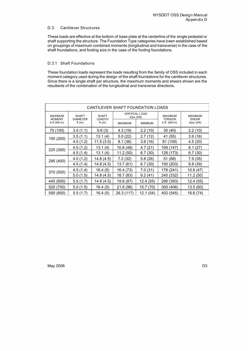
8/18/2019 OSS Manual 2008 USC Update
http://slidepdf.com/reader/full/oss-manual-2008-usc-update 39/46
NYSDOT OSS Design Manual Appendix D
May 2008 D3
D.3 Cantilever Structures
These loads are effective at the bottom of base plate at the centerline of the single pedestal orshaft supporting the structure. The Foundation Type categories have been established basedon groupings of maximum combined moments (longitudinal and transverse) in the case of theshaft foundations, and footing size in the case of the footing foundations.
D.3.1 Shaft Foundations
These foundation loads represent the loads resulting from the family of OSS included in eachmoment category used during the design of the shaft foundations for the cantilever structures.Since there is a single shaft per structure, the maximum moments and shears shown are theresultants of the combination of the longitudinal and transverse directions.
CANTILEVER SHAFT FOUNDATION LOADSVERTICAL LOAD
kips (kN)MAXIMUMMOMENTk-ft (kN-m)
SHAFTDIAMETER
ft (m)
SHAFTLENGTH
ft (m) MAXIMUM MINIMUM
MAXIMUMTORSION
k-ft (kN-m)
MAXIMUMSHEAR
kips (kN)
75 (100) 3.5 (1.1) 9.8 (3) 4.3 (19) 2.2 (10) 30 (40) 2.2 (10)
3.5 (1.1) 13.1 (4) 5.0 (22) 2.7 (12) 41 (55) 3.6 (16)150 (200)
4.0 (1.2) 11.5 (3.5) 8.1 (36) 3.6 (16) 81 (109) 4.5 (20)
4.0 (1.2) 13.1 (4) 10.8 (48) 4.7 (21) 109 (147) 6.1 (27)225 (300)
4.5 (1.4) 13.1 (4) 11.2 (50) 6.7 (30) 128 (173) 6.7 (30)
4.0 (1.2) 14.8 (4.5) 7.2 (32) 5.8 (26) 51 (68) 7.9 (35)
295 (400) 4.5 (1.4) 14.8 (4.5) 13.7 (61) 6.7 (30) 150 (203) 8.8 (39)
4.5 (1.4) 16.4 (5) 16.4 (73) 7.0 (31) 178 (241) 10.6 (47)370 (500)
5.0 (1.5) 14.8 (4.5) 18.7 (83) 9.2 (41) 245 (332) 11.2 (50)
445 (600) 5.5 (1.7) 14.8 (4.5) 19.6 (87) 12.4 (55) 290 (393) 12.4 (55)
520 (700) 5.0 (1.5) 16.4 (5) 21.6 (96) 15.7 (70) 300 (406) 13.5 (60)
590 (800) 5.5 (1.7) 16.4 (5) 26.3 (117) 12.1 (54) 402 (545) 16.6 (74)
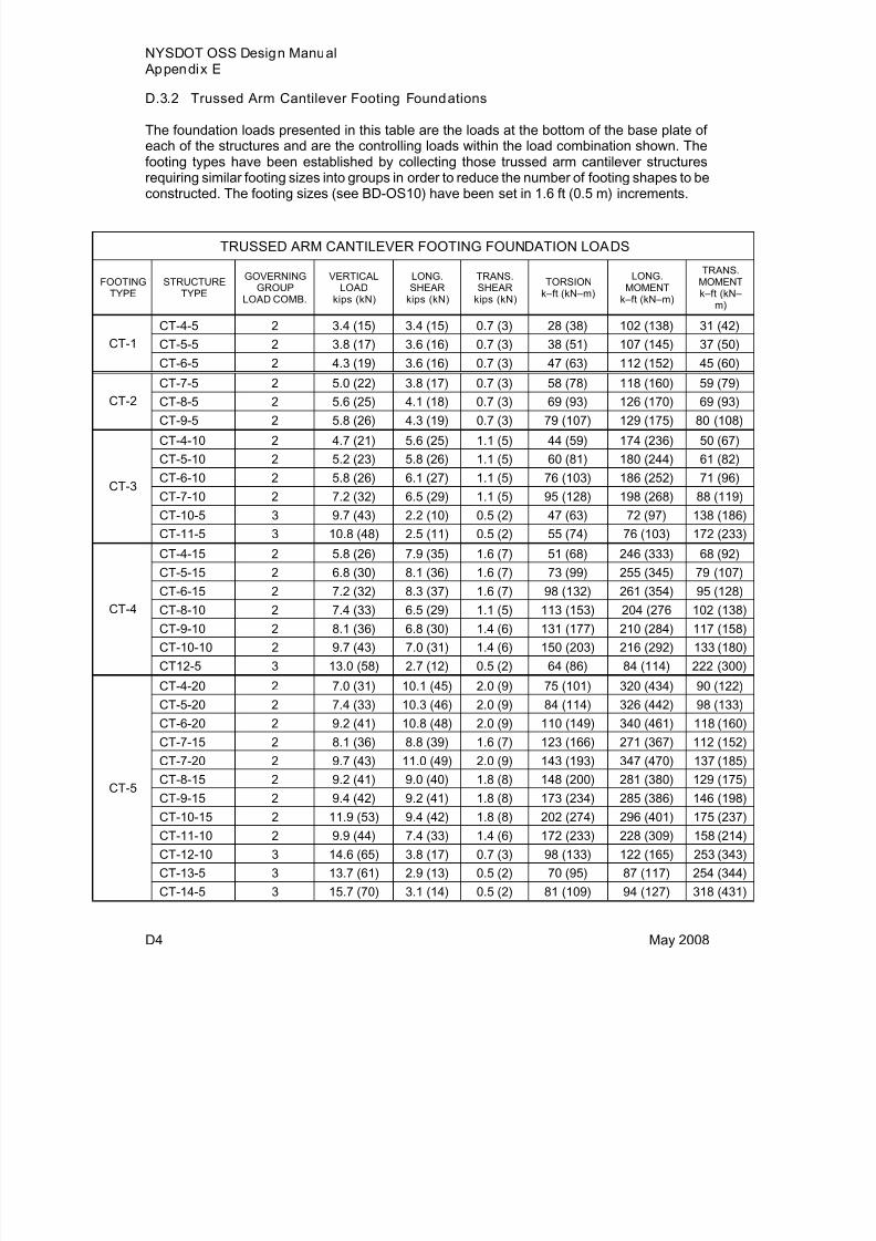
8/18/2019 OSS Manual 2008 USC Update
http://slidepdf.com/reader/full/oss-manual-2008-usc-update 40/46
NYSDOT OSS Design Manual Appendix E
D4 May 2008
D.3.2 Trussed Arm Cantilever Footing Foundations
The foundation loads presented in this table are the loads at the bottom of the base plate ofeach of the structures and are the controlling loads within the load combination shown. Thefooting types have been established by collecting those trussed arm cantilever structuresrequiring similar footing sizes into groups in order to reduce the number of footing shapes to be
constructed. The footing sizes (see BD-OS10) have been set in 1.6 ft (0.5 m) increments.
TRUSSED ARM CANTILEVER FOOTING FOUNDATION LOADS
FOOTINGTYPE
STRUCTURETYPE
GOVERNINGGROUP
LOAD COMB.
VERTICALLOAD
kips (kN)
LONG.SHEAR
kips (kN)
TRANS.SHEAR
kips (kN)
TORSIONk–ft (kN–m)
LONG.MOMENT
k–ft (kN–m)
TRANS.MOMENTk–ft (kN–
m)
CT-4-5 2 3.4 (15) 3.4 (15) 0.7 (3) 28 (38) 102 (138) 31 (42)
CT-5-5 2 3.8 (17) 3.6 (16) 0.7 (3) 38 (51) 107 (145) 37 (50)CT-1
CT-6-5 2 4.3 (19) 3.6 (16) 0.7 (3) 47 (63) 112 (152) 45 (60)
CT-7-5 2 5.0 (22) 3.8 (17) 0.7 (3) 58 (78) 118 (160) 59 (79)CT-8-5 2 5.6 (25) 4.1 (18) 0.7 (3) 69 (93) 126 (170) 69 (93)CT-2
CT-9-5 2 5.8 (26) 4.3 (19) 0.7 (3) 79 (107) 129 (175) 80 (108)
CT-4-10 2 4.7 (21) 5.6 (25) 1.1 (5) 44 (59) 174 (236) 50 (67)
CT-5-10 2 5.2 (23) 5.8 (26) 1.1 (5) 60 (81) 180 (244) 61 (82)
CT-6-10 2 5.8 (26) 6.1 (27) 1.1 (5) 76 (103) 186 (252) 71 (96)
CT-7-10 2 7.2 (32) 6.5 (29) 1.1 (5) 95 (128) 198 (268) 88 (119)
CT-10-5 3 9.7 (43) 2.2 (10) 0.5 (2) 47 (63) 72 (97) 138 (186)
CT-3
CT-11-5 3 10.8 (48) 2.5 (11) 0.5 (2) 55 (74) 76 (103) 172 (233)
CT-4-15 2 5.8 (26) 7.9 (35) 1.6 (7) 51 (68) 246 (333) 68 (92)
CT-5-15 2 6.8 (30) 8.1 (36) 1.6 (7) 73 (99) 255 (345) 79 (107)CT-6-15 2 7.2 (32) 8.3 (37) 1.6 (7) 98 (132) 261 (354) 95 (128)
CT-8-10 2 7.4 (33) 6.5 (29) 1.1 (5) 113 (153) 204 (276 102 (138)
CT-9-10 2 8.1 (36) 6.8 (30) 1.4 (6) 131 (177) 210 (284) 117 (158)
CT-10-10 2 9.7 (43) 7.0 (31) 1.4 (6) 150 (203) 216 (292) 133 (180)
CT-4
CT12-5 3 13.0 (58) 2.7 (12) 0.5 (2) 64 (86) 84 (114) 222 (300)
CT-4-20 2 7.0 (31) 10.1 (45) 2.0 (9) 75 (101) 320 (434) 90 (122)
CT-5-20 2 7.4 (33) 10.3 (46) 2.0 (9) 84 (114) 326 (442) 98 (133)
CT-6-20 2 9.2 (41) 10.8 (48) 2.0 (9) 110 (149) 340 (461) 118 (160)
CT-7-15 2 8.1 (36) 8.8 (39) 1.6 (7) 123 (166) 271 (367) 112 (152)
CT-7-20 2 9.7 (43) 11.0 (49) 2.0 (9) 143 (193) 347 (470) 137 (185)CT-8-15 2 9.2 (41) 9.0 (40) 1.8 (8) 148 (200) 281 (380) 129 (175)
CT-9-15 2 9.4 (42) 9.2 (41) 1.8 (8) 173 (234) 285 (386) 146 (198)
CT-10-15 2 11.9 (53) 9.4 (42) 1.8 (8) 202 (274) 296 (401) 175 (237)
CT-11-10 2 9.9 (44) 7.4 (33) 1.4 (6) 172 (233) 228 (309) 158 (214)
CT-12-10 3 14.6 (65) 3.8 (17) 0.7 (3) 98 (133) 122 (165) 253 (343)
CT-13-5 3 13.7 (61) 2.9 (13) 0.5 (2) 70 (95) 87 (117) 254 (344)
CT-5
CT-14-5 3 15.7 (70) 3.1 (14) 0.5 (2) 81 (109) 94 (127) 318 (431)
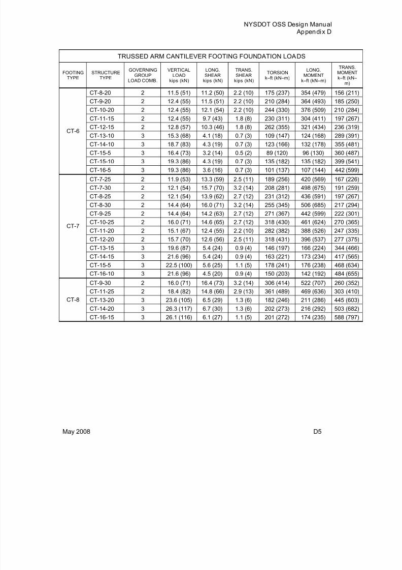
8/18/2019 OSS Manual 2008 USC Update
http://slidepdf.com/reader/full/oss-manual-2008-usc-update 41/46
NYSDOT OSS Design Manual Appendix D
May 2008 D5
TRUSSED ARM CANTILEVER FOOTING FOUNDATION LOADS
FOOTINGTYPE
STRUCTURETYPE
GOVERNINGGROUP
LOAD COMB.
VERTICALLOAD
kips (kN)
LONG.SHEAR
kips (kN)
TRANS.SHEAR
kips (kN)
TORSIONk–ft (kN–m)
LONG.MOMENT
k–ft (kN–m)
TRANSMOMENTk–ft (kN–
m)
CT-8-20 2 11.5 (51) 11.2 (50) 2.2 (10) 175 (237) 354 (479) 156 (21
CT-9-20 2 12.4 (55) 11.5 (51) 2.2 (10) 210 (284) 364 (493) 185 (25
CT-10-20 2 12.4 (55) 12.1 (54) 2.2 (10) 244 (330) 376 (509) 210 (284
CT-11-15 2 12.4 (55) 9.7 (43) 1.8 (8) 230 (311) 304 (411) 197 (26
CT-12-15 2 12.8 (57) 10.3 (46) 1.8 (8) 262 (355) 321 (434) 236 (31
CT-13-10 3 15.3 (68) 4.1 (18) 0.7 (3) 109 (147) 124 (168) 289 (39
CT-14-10 3 18.7 (83) 4.3 (19) 0.7 (3) 123 (166) 132 (178) 355 (48
CT-15-5 3 16.4 (73) 3.2 (14) 0.5 (2) 89 (120) 96 (130) 360 (48
CT-15-10 3 19.3 (86) 4.3 (19) 0.7 (3) 135 (182) 135 (182) 399 (54
CT-6
CT-16-5 3 19.3 (86) 3.6 (16) 0.7 (3) 101 (137) 107 (144) 442 (59
CT-7-25 2 11.9 (53) 13.3 (59) 2.5 (11) 189 (256) 420 (569) 167 (22
CT-7-30 2 12.1 (54) 15.7 (70) 3.2 (14) 208 (281) 498 (675) 191 (25
CT-8-25 2 12.1 (54) 13.9 (62) 2.7 (12) 231 (312) 436 (591) 197 (26
CT-8-30 2 14.4 (64) 16.0 (71) 3.2 (14) 255 (345) 506 (685) 217 (294
CT-9-25 2 14.4 (64) 14.2 (63) 2.7 (12) 271 (367) 442 (599) 222 (30
CT-10-25 2 16.0 (71) 14.6 (65) 2.7 (12) 318 (430) 461 (624) 270 (36
CT-11-20 2 15.1 (67) 12.4 (55) 2.2 (10) 282 (382) 388 (526) 247 (33
CT-12-20 2 15.7 (70) 12.6 (56) 2.5 (11) 318 (431) 396 (537) 277 (37
CT-13-15 3 19.6 (87) 5.4 (24) 0.9 (4) 146 (197) 166 (224) 344 (46
CT-14-15 3 21.6 (96) 5.4 (24) 0.9 (4) 163 (221) 173 (234) 417 (56
CT-15-5 3 22.5 (100) 5.6 (25) 1.1 (5) 178 (241) 176 (238) 468 (634
CT-7
CT-16-10 3 21.6 (96) 4.5 (20) 0.9 (4) 150 (203) 142 (192) 484 (65
CT-9-30 2 16.0 (71) 16.4 (73) 3.2 (14) 306 (414) 522 (707) 260 (352
CT-11-25 2 18.4 (82) 14.8 (66) 2.9 (13) 361 (489) 469 (636) 303 (41
CT-13-20 3 23.6 (105) 6.5 (29) 1.3 (6) 182 (246) 211 (286) 445 (603
CT-14-20 3 26.3 (117) 6.7 (30) 1.3 (6) 202 (273) 216 (292) 503 (682
CT-8
CT-16-15 3 26.1 (116) 6.1 (27) 1.1 (5) 201 (272) 174 (235) 588 (797
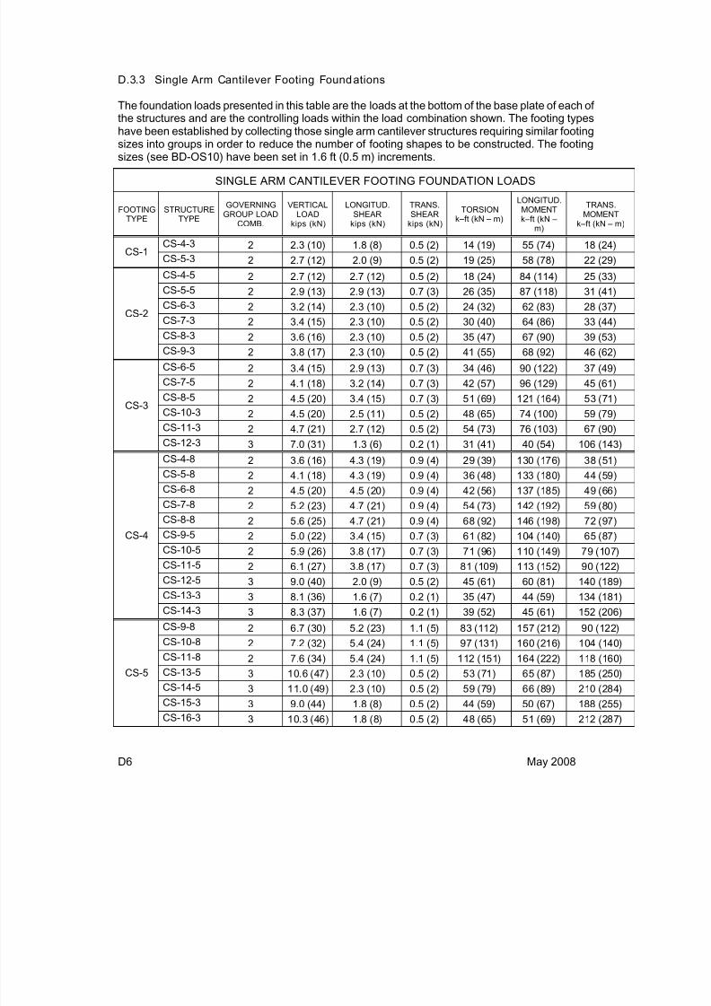
8/18/2019 OSS Manual 2008 USC Update
http://slidepdf.com/reader/full/oss-manual-2008-usc-update 42/46
D6 May 2008
D.3.3 Single Arm Cantilever Footing Foundations
The foundation loads presented in this table are the loads at the bottom of the base plate of each ofthe structures and are the controlling loads within the load combination shown. The footing typeshave been established by collecting those single arm cantilever structures requiring similar footingsizes into groups in order to reduce the number of footing shapes to be constructed. The footing
sizes (see BD-OS10) have been set in 1.6 ft (0.5 m) increments.
SINGLE ARM CANTILEVER FOOTING FOUNDATION LOADS
FOOTINGTYPE
STRUCTURETYPE
GOVERNINGGROUP LOAD
COMB.
VERTICALLOAD
kips (kN)
LONGITUD.SHEAR
kips (kN)
TRANS.SHEAR
kips (kN)
TORSIONk–ft (kN – m)
LONGITUD.MOMENTk–ft (kN –
m)
TRANS.MOMENT
k–ft (kN – m)
CS-4-3 2 2.3 (10) 1.8 (8) 0.5 (2) 14 (19) 55 (74) 18 (24)CS-1
CS-5-3 2 2.7 (12) 2.0 (9) 0.5 (2) 19 (25) 58 (78) 22 (29)
CS-4-5 2 2.7 (12) 2.7 (12) 0.5 (2) 18 (24) 84 (114) 25 (33)
CS-5-5 2 2.9 (13) 2.9 (13) 0.7 (3) 26 (35) 87 (118) 31 (41)
CS-6-3 2 3.2 (14) 2.3 (10) 0.5 (2) 24 (32) 62 (83) 28 (37)CS-7-3 2 3.4 (15) 2.3 (10) 0.5 (2) 30 (40) 64 (86) 33 (44)
CS-8-3 2 3.6 (16) 2.3 (10) 0.5 (2) 35 (47) 67 (90) 39 (53)
CS-2
CS-9-3 2 3.8 (17) 2.3 (10) 0.5 (2) 41 (55) 68 (92) 46 (62)
CS-6-5 2 3.4 (15) 2.9 (13) 0.7 (3) 34 (46) 90 (122) 37 (49)
CS-7-5 2 4.1 (18) 3.2 (14) 0.7 (3) 42 (57) 96 (129) 45 (61)
CS-8-5 2 4.5 (20) 3.4 (15) 0.7 (3) 51 (69) 121 (164) 53 (71)
CS-10-3 2 4.5 (20) 2.5 (11) 0.5 (2) 48 (65) 74 (100) 59 (79)
CS-11-3 2 4.7 (21) 2.7 (12) 0.5 (2) 54 (73) 76 (103) 67 (90)
CS-3
CS-12-3 3 7.0 (31) 1.3 (6) 0.2 (1) 31 (41) 40 (54) 106 (143)
CS-4-8 2 3.6 (16) 4.3 (19) 0.9 (4) 29 (39) 130 (176) 38 (51)
CS-5-8 2 4.1 (18) 4.3 (19) 0.9 (4) 36 (48) 133 (180) 44 (59)
CS-6-8 2 4.5 (20) 4.5 (20) 0.9 (4) 42 (56) 137 (185) 49 (66)
CS-7-8 2 5.2 (23) 4.7 (21) 0.9 (4) 54 (73) 142 (192) 59 (80)
CS-8-8 2 5.6 (25) 4.7 (21) 0.9 (4) 68 (92) 146 (198) 72 (97)
CS-9-5 2 5.0 (22) 3.4 (15) 0.7 (3) 61 (82) 104 (140) 65 (87)
CS-10-5 2 5.9 (26) 3.8 (17) 0.7 (3) 71 (96) 110 (149) 79 (107)
CS-11-5 2 6.1 (27) 3.8 (17) 0.7 (3) 81 (109) 113 (152) 90 (122)
CS-12-5 3 9.0 (40) 2.0 (9) 0.5 (2) 45 (61) 60 (81) 140 (189)
CS-13-3 3 8.1 (36) 1.6 (7) 0.2 (1) 35 (47) 44 (59) 134 (181)
CS-4
CS-14-3 3 8.3 (37) 1.6 (7) 0.2 (1) 39 (52) 45 (61) 152 (206)
CS-9-8 2 6.7 (30) 5.2 (23) 1.1 (5) 83 (112) 157 (212) 90 (122)
CS-10-8 2 7.2 (32) 5.4 (24) 1.1 (5) 97 (131) 160 (216) 104 (140)
CS-11-8 2 7.6 (34) 5.4 (24) 1.1 (5) 112 (151) 164 (222) 118 (160)
CS-13-5 3 10.6 (47) 2.3 (10) 0.5 (2) 53 (71) 65 (87) 185 (250)
CS-14-5 3 11.0 (49) 2.3 (10) 0.5 (2) 59 (79) 66 (89) 210 (284)
CS-15-3 3 9.0 (44) 1.8 (8) 0.5 (2) 44 (59) 50 (67) 188 (255)
CS-5
CS-16-3 3 10.3 (46) 1.8 (8) 0.5 (2) 48 (65) 51 (69) 212 (287)

8/18/2019 OSS Manual 2008 USC Update
http://slidepdf.com/reader/full/oss-manual-2008-usc-update 43/46
NYSDOT OSS Design Manual Appendix D
May 2008 D7
SINGLE ARM CANTILEVER FOOTING FOUNDATION LOADS
FOOTINGTYPE
STRUCTURETYPE
GOVERNINGGROUP LOAD
COMB.
VERTICALLOAD
kips (kN)
LONGITUD.SHEAR
kips (kN)
TRANS.SHEAR
kips (kN)
TORSIONk–ft (kN – m)
LONGITUD.MOMENTk–ft (kN –
m)
TRANS.MOMENT
k–ft (kN – m)
CS-12-8 2 8.3 (37) 5.6 (25) 1.1 (5) 128 (173) 171 (231) 140 (189)
CS-13-8 2 9.2 (41) 5.8 (26) 1.1 (5) 143 (194) 177 (239) 157 (213)
CS-14-8 3 14.4 (64) 2.9 (13) 0.7 (3) 79 (107) 92 (124) 280 (379)
CS-15-5 3 11.5 (51) 2.2 (10) 0.5 (2) 64 (86) 68 (92) 237 (321)
CS-6
CS-16-5 3 12.4 (55) 2.2 (10) 0.5 (2) 70 (94) 70 (95) 266 (360)
CS-15-8 3 16.4 (73) 3.1 (14) 0.7 (3) 87 (118) 93 (126) 315 (427)CS-7
CS-16-8 3 17.1 (76) 3.1 (14) 0.7 (3) 96 (129) 95 (128) 354 (479)

8/18/2019 OSS Manual 2008 USC Update
http://slidepdf.com/reader/full/oss-manual-2008-usc-update 44/46
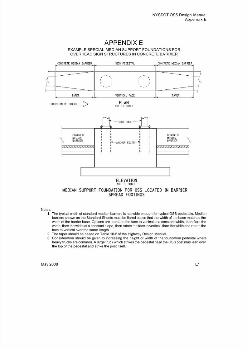
8/18/2019 OSS Manual 2008 USC Update
http://slidepdf.com/reader/full/oss-manual-2008-usc-update 45/46
NYSDOT OSS Design Manual Appendix E
May 2008 E1
APPENDIX EEXAMPLE SPECIAL MEDIAN SUPPORT FOUNDATIONS FOR
OVERHEAD SIGN STRUCTURES IN CONCRETE BARRIER
Notes:1. The typical width of standard median barriers is not wide enough for typical OSS pedestals. Median
barriers shown on the Standard Sheets must be flared out so that the width of the base matches thewidth of the barrier base. Options are to rotate the face to vertical at a constant width, then flare thewidth; flare the width at a constant slope, then rotate the face to vertical; flare the width and rotate theface to vertical over the same length.
2. The taper should be based on Table 10-5 of the Highway Design Manual.3. Consideration should be given to increasing the height or width of the foundation pedestal where
heavy trucks are common. A large truck which strikes the pedestal near the OSS post may lean overthe top of the pedestal and strike the post itself.

8/18/2019 OSS Manual 2008 USC Update
http://slidepdf.com/reader/full/oss-manual-2008-usc-update 46/46
Notes:1. The typical width of standard median barriers is not wide enough for typical OSS pedestals. Median
barriers shown on the Standard Sheets must be flared out so that the width of the base matches thewidth of the barrier base. Options are to rotate the face to vertical at a constant width, then flare the
width; flare the width at a constant slope, then rotate the face to vertical; flare the width and rotate theface to vertical over the same length.2. The taper should be based on Table 10-5 of the Highway Design Manual.3. Consideration should be given to increasing the height or width of the foundation pedestal where
heavy trucks are common. A large truck which strikes the pedestal near the OSS post may lean overthe top of the pedestal and strike the post itself.