osseointegration of titanium implants in onlay of cerament
TRANSCRIPT
Journal of
Functional
Biomaterials
Article
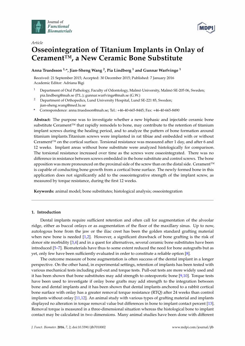
Osseointegration of Titanium Implants in Onlay ofCerament™, a New Ceramic Bone SubstituteAnna Truedsson 1,*, Jian-Sheng Wang 2, Pia Lindberg 1 and Gunnar Warfvinge 1
Received: 21 September 2015; Accepted: 30 December 2015; Published: 7 January 2016Academic Editor: Adriana Bigi
1 Department of Oral Pathology, Faculty of Odontology, Malmö University, Malmö SE-205 06, Sweden;[email protected] (P.L.); [email protected] (G.W.)
2 Department of Orthopedics, Lund University Hospital, Lund SE-221 85, Sweden;[email protected]
* Correspondence: [email protected]; Tel.: +46-40-665-8445; Fax: +46-40-665-8490
Abstract: The purpose was to investigate whether a new biphasic and injectable ceramic bonesubstitute Cerament™ that rapidly remodels to bone, may contribute to the retention of titaniumimplant screws during the healing period, and to analyze the pattern of bone formation aroundtitanium implants.Titanium screws were implanted in rat tibiae and embedded with or withoutCerament™ on the cortical surface. Torsional resistance was measured after 1 day, and after 6 and12 weeks. Implant areas without bone substitute were analyzed histologically for comparison.The torsional resistance increased over time as the screws were osseointegrated. There was nodifference in resistance between screws embedded in the bone substitute and control screws. The boneapposition was more pronounced on the proximal side of the screw than on the distal side. Cerament™is capable of conducting bone growth from a cortical bone surface. The newly formed bone in thisapplication does not significantly add to the osseointegrative strength of the implant screw, asmeasured by torque resistance, during the first 12 weeks.
Keywords: animal model; bone substitutes; histological analysis; osseointegration
1. Introduction
Dental implants require sufficient retention and often call for augmentation of the alveolarridge, either as buccal onlays or as augmentation of the floor of the maxillary sinus. Up to now,autologous bone from the jaw or the iliac crest has been the golden standard grafting materialwhen new bone is needed [1,2]. However, a significant drawback of bone grafting is the risk ofdonor site morbidity [3,4] and in a quest for alternatives, several ceramic bone substitutes have beenintroduced [5–7]. Biomaterials have thus to some extent reduced the need for bone autografts but asyet, only few have been sufficiently evaluated in order to constitute a reliable option [8].
The outcome measure of bone augmentation is often success of the dental implant in a longerperspective. On the other hand, in experimental settings, retention of implants has been tested withvarious mechanical tests including pull-out and torque tests. Pull-out tests are more widely used andit has been shown that bone substitutes may add strength to osteoporotic bone [9,10]. Torque testshave been used to investigate if onlay bone grafts may add strength to the integration betweenbone and dental implants and it has been shown that dental implants anchored to a rabbit corticalbone surface with onlay has a greater removal torque resistance (RTQ) after 24 weeks than controlimplants without onlay [11,12]. An animal study with various types of grafting material and implantsdisplayed no alteration in torque removal value but differences in bone to implant contact percent [13].Removal torque is measured in a three-dimensional situation whereas the histological bone to implantcontact may be calculated in two dimensions. Many animal studies have been done with different
J. Funct. Biomater. 2016, 7, 2; doi:10.3390/jfb7010002 www.mdpi.com/journal/jfb

J. Funct. Biomater. 2016, 7, 2 2 of 9
implant surface in the purpose to measure correlation between removal torque and bone to implantcontact/bone volume [14–16].
Cerament™ is a new ceramic bone substitute that was originally designed to treat spinal fracturesand to fill bone voids. The substitute was used in a recent study of 33 patients who underwentpercutaneous vertebroplasty after osteoporotic and/or traumatic vertebral fractures. Radiologicaland clinical outcome was assessed by radiography, CT, and MRI, and 12 months after surgery, thefractures were stable and new bone formation visible [17]. It is a biphasic mixture of calcium sulphatehemi-hydrate (CSH) and hydroxyapatite (HA) that has good compressive strength [18]. CSH is a bonesubstitute with well-documented ability to support healing in bone defects [19] but the usefulnessof pure CSH in a clinical setting is limited due to its low resistance to resorption [20]. In contrast,hydroxyapatite (HA) has both good mechanical strength and resistance to resorption as well asosteoconductive properties [6]. In Cerament™, the CSH component is readily dissolved leaving HA asa three-dimensional osteoconductive matrix that allows ingrowth of osteogenic cells and vessels. Hence,Cerament™ has many features that are desirable in oral and maxillofacial reconstructive surgery.
Experimental evaluation of bone substitutes have primarily been conducted through analysis ofbone ingrowth into drilled defects and other artificial bone voids. Clinically however, the surgeonis often confronted with a need to augment rather than fill and there is a need for studies on bonesubstitute onlays. In an experimental onlay model, we have previously shown that Cerament™ mayguide bone to augment a cortical bone surface in rats, detailing histological features of the boneremodeling [21]. The purpose of this study was to investigate if Cerament™, and the newly formedbone within it, may also contribute to the retention of implants during the healing period. We havealso histologically studied the bone healing reaction around implants in rat tibia.
2. Results and Discussion
2.1. Biomechanical Analysis
The biomechanical test was performed for all time periods (1 day, 6 and 12 weeks). The maximumRTQ increased from 1 day to 6 weeks and further to 12 weeks (p < 0.001; Figure 1). However, therewere no significant differences between the RTQ values of titanium screws implanted with Cerament™and the controls without, at any time period.
J. Funct. Biomater. 2016, 7, 2
2
different implant surface in the purpose to measure correlation between removal torque and bone to
implant contact/bone volume [14–16].
Cerament™ is a new ceramic bone substitute that was originally designed to treat spinal
fractures and to fill bone voids. The substitute was used in a recent study of 33 patients who
underwent percutaneous vertebroplasty after osteoporotic and/or traumatic vertebral fractures.
Radiological and clinical outcome was assessed by radiography, CT, and MRI, and 12 months after
surgery, the fractures were stable and new bone formation visible [17]. It is a biphasic mixture of
calcium sulphate hemi‐hydrate (CSH) and hydroxyapatite (HA) that has good compressive strength
[18]. CSH is a bone substitute with well‐documented ability to support healing in bone defects [19]
but the usefulness of pure CSH in a clinical setting is limited due to its low resistance to resorption
[20]. In contrast, hydroxyapatite (HA) has both good mechanical strength and resistance to resorption
as well as osteoconductive properties [6]. In Cerament™, the CSH component is readily dissolved
leaving HA as a three‐dimensional osteoconductive matrix that allows ingrowth of osteogenic cells
and vessels. Hence, Cerament™ has many features that are desirable in oral and maxillofacial
reconstructive surgery.
Experimental evaluation of bone substitutes have primarily been conducted through analysis of
bone ingrowth into drilled defects and other artificial bone voids. Clinically however, the surgeon is
often confronted with a need to augment rather than fill and there is a need for studies on bone
substitute onlays. In an experimental onlay model, we have previously shown that Cerament™ may
guide bone to augment a cortical bone surface in rats, detailing histological features of the bone
remodeling [21]. The purpose of this study was to investigate if Cerament™, and the newly formed
bone within it, may also contribute to the retention of implants during the healing period. We have
also histologically studied the bone healing reaction around implants in rat tibia.
2. Results and Discussion
2.1. Biomechanical Analysis
The biomechanical test was performed for all time periods (1 day, 6 and 12 weeks). The
maximum RTQ increased from 1 day to 6 weeks and further to 12 weeks (p < 0.001; Figure 1).
However, there were no significant differences between the RTQ values of titanium screws implanted
with Cerament™ and the controls without, at any time period.
Figure 1. Torque resistance of titanium screws implanted in rat tibia after different periods of
osseointegration. The bars denote mean maximum torque resistance from eight measurements (seven
at day 1). Thin lines represent 1 SD.
The RTQ plots displayed three main patterns. The first pattern represented no, or very subtle,
osseointegration and comprised a transient increase up to a level of up to 40 Nmm and a subsequent
level RTQ value (Figure 2a). The second pattern was a gradual increase up to 80 Nmm or more and
a gradual leveling (Figure 2b). The pattern was interpreted as osseointegration in a plastic, partly
Figure 1. Torque resistance of titanium screws implanted in rat tibia after different periods ofosseointegration. The bars denote mean maximum torque resistance from eight measurements (sevenat day 1). Thin lines represent 1 SD.
The RTQ plots displayed three main patterns. The first pattern represented no, or very subtle,osseointegration and comprised a transient increase up to a level of up to 40 Nmm and a subsequentlevel RTQ value (Figure 2a). The second pattern was a gradual increase up to 80 Nmm or more anda gradual leveling (Figure 2b). The pattern was interpreted as osseointegration in a plastic, partly

J. Funct. Biomater. 2016, 7, 2 3 of 9
mineralized bone. The third pattern was an initial increase followed by a break at 20–40 Nmm followedby a short level period. Thereafter, the RTQ value increased again and finally levelled out (Figure 2c).Many of the graphs also displayed a slight vibration, visualized as double curves.
Figure 2. (a) RTQ 6 weeks Cerament™; (b) RTQ 12 weeks control; (c) RTQ 12 weeks Cerament™.
At day 1, RTQ could only be attributed to friction and not to osseointegration and RTQ neverexceeded 13 Nmm (7.6 ˘ 3.5 Nmm). There was no significant difference between Cerament sites andcontrols showing that the set Cerament™ did not add RTQ strength.
At 6 weeks, the specimens could be categorized into two groups according to RTQ values.Eight specimens, four Cerament™ and four controls, increased to a first peak after which there wasa short decline and subsequently a level RTQ plot reaching a maximum of 36.7 ˘ 7.4 Nmm. The firstpeak was interpreted as a breakage in the attachment. The remaining eight specimens displayed

J. Funct. Biomater. 2016, 7, 2 4 of 9
a significant increase in RTQ up to a maximum of 93.5 ˘ 23.0 Nmm. Four of these specimens did, andfour did not, display a clear initial break.
At 12 weeks, all specimens reached at least 80 Nmm with a maximum RTQ of 128.4 ˘ 45.5 forCerament™ sites and 121.2 ˘ 30.6 for controls. Eleven of the RTQ plots displayed a clear peak.
2.2. Histology and Histomorphometry
In many specimens the original cortical medial base line was fairly resorbed and in somespecimens, the base line had disappeared so that the cortex had been translocated to a peripheralposition. This was primarily observed in the experimental zone next to the tibial growth plate (frames Aand B) (Figure 3a).
A fan of thin trabeculae radiated from the growth plate making it somewhat difficult to definethe outline of the inner cortical bone surface at times. Therefore, an imaginary inner boundary wasextrapolated from the inner border of the cortex at the distal side (Figure 3b).
J. Funct. Biomater. 2016, 7, 2
4
At 12 weeks, all specimens reached at least 80 Nmm with a maximum RTQ of 128.4 ± 45.5 for
Cerament™ sites and 121.2 ± 30.6 for controls. Eleven of the RTQ plots displayed a clear peak.
2.2. Histology and Histomorphometry
In many specimens the original cortical medial base line was fairly resorbed and in some
specimens, the base line had disappeared so that the cortex had been translocated to a peripheral
position. This was primarily observed in the experimental zone next to the tibial growth plate (frames
A and B) (Figure 3a).
A fan of thin trabeculae radiated from the growth plate making it somewhat difficult to define
the outline of the inner cortical bone surface at times. Therefore, an imaginary inner boundary was
extrapolated from the inner border of the cortex at the distal side (Figure 3b).
(a) (b)
Figure 3. (a) Illustration of measuring frames around titanium screw implanted in rat tibia without
Cerament™. Frame A is closest to the proximal growth plate. Ground section, Goldner stain; (b)
Titanium screw implanted in rat tibia without Cerament™. An imaginary base line is extrapolated
from the residual distal portion (right) of the inner cortical curvature. Ground section, Goldner stain.
After a maximum at 3 weeks (874 ± 213 μm), the mean bone thickness decreased at 6 (772 ± 128 μm),
and further at 12 weeks (635 ± 73 μm; p < 0.05; Figure 4). The bone was thicker at the proximal than
at the distal side of the titanium screw, measured from the imaginary base line. One outlier displayed
an extreme bone thickness of approximately 2400 μm at 12 weeks. This animal was excluded from
the analysis. The maximum cortical bone thickness was significantly greater at the proximal than at
the distal side, at 12 weeks (p < 0.05).
Figure 4. The bars denote mean bone thickness within each measuring frame (A–D). The line denotes
mean thickness of all frames. * significant difference (p < 0.05).
Figure 3. (a) Illustration of measuring frames around titanium screw implanted in rat tibia withoutCerament™. Frame A is closest to the proximal growth plate. Ground section, Goldner stain;(b) Titanium screw implanted in rat tibia without Cerament™. An imaginary base line is extrapolatedfrom the residual distal portion (right) of the inner cortical curvature. Ground section, Goldner stain.
After a maximum at 3 weeks (874 ˘ 213 µm), the mean bone thickness decreased at6 (772 ˘ 128 µm), and further at 12 weeks (635 ˘ 73 µm; p < 0.05; Figure 4). The bone was thickerat the proximal than at the distal side of the titanium screw, measured from the imaginary base line.One outlier displayed an extreme bone thickness of approximately 2400 µm at 12 weeks. This animalwas excluded from the analysis. The maximum cortical bone thickness was significantly greater at theproximal than at the distal side, at 12 weeks (p < 0.05).
J. Funct. Biomater. 2016, 7, 2
4
At 12 weeks, all specimens reached at least 80 Nmm with a maximum RTQ of 128.4 ± 45.5 for
Cerament™ sites and 121.2 ± 30.6 for controls. Eleven of the RTQ plots displayed a clear peak.
2.2. Histology and Histomorphometry
In many specimens the original cortical medial base line was fairly resorbed and in some
specimens, the base line had disappeared so that the cortex had been translocated to a peripheral
position. This was primarily observed in the experimental zone next to the tibial growth plate (frames
A and B) (Figure 3a).
A fan of thin trabeculae radiated from the growth plate making it somewhat difficult to define
the outline of the inner cortical bone surface at times. Therefore, an imaginary inner boundary was
extrapolated from the inner border of the cortex at the distal side (Figure 3b).
(a) (b)
Figure 3. (a) Illustration of measuring frames around titanium screw implanted in rat tibia without
Cerament™. Frame A is closest to the proximal growth plate. Ground section, Goldner stain; (b)
Titanium screw implanted in rat tibia without Cerament™. An imaginary base line is extrapolated
from the residual distal portion (right) of the inner cortical curvature. Ground section, Goldner stain.
After a maximum at 3 weeks (874 ± 213 μm), the mean bone thickness decreased at 6 (772 ± 128 μm),
and further at 12 weeks (635 ± 73 μm; p < 0.05; Figure 4). The bone was thicker at the proximal than
at the distal side of the titanium screw, measured from the imaginary base line. One outlier displayed
an extreme bone thickness of approximately 2400 μm at 12 weeks. This animal was excluded from
the analysis. The maximum cortical bone thickness was significantly greater at the proximal than at
the distal side, at 12 weeks (p < 0.05).
Figure 4. The bars denote mean bone thickness within each measuring frame (A–D). The line denotes
mean thickness of all frames. * significant difference (p < 0.05). Figure 4. The bars denote mean bone thickness within each measuring frame (A–D). The line denotesmean thickness of all frames. * significant difference (p < 0.05).
J. Funct. Biomater. 2016, 7, 2 5 of 9
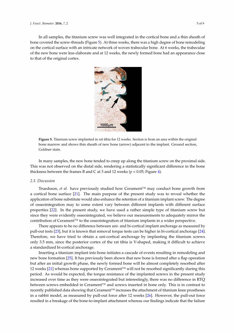
In all samples, the titanium screw was well integrated in the cortical bone and a thin sheath ofbone covered the screw-threads (Figure 5). At three weeks, there was a high degree of bone remodelingon the cortical surface with an intricate network of woven trabecular bone. At 6 weeks, the trabeculaeof the new bone were less elaborate and at 12 weeks, the newly formed bone had an appearance closeto that of the original cortex.
J. Funct. Biomater. 2016, 7, 2
5
In all samples, the titanium screw was well integrated in the cortical bone and a thin sheath of
bone covered the screw‐threads (Figure 5). At three weeks, there was a high degree of bone
remodeling on the cortical surface with an intricate network of woven trabecular bone. At 6 weeks,
the trabeculae of the new bone were less elaborate and at 12 weeks, the newly formed bone had an
appearance close to that of the original cortex.
Figure 5. Titanium screw implanted in rat tibia for 12 weeks. Section is from an area within the
original bone marrow and shows thin sheath of new bone (arrow) adjacent to the implant. Ground
section, Goldner stain.
In many samples, the new bone tended to creep up along the titanium screw on the proximal
side. This was not observed on the distal side, rendering a statistically significant difference in the
bone thickness between the frames B and C at 3 and 12 weeks (p < 0.05; Figure 4).
2.3. Discussion
Truedsson, et al. have previously studied how Cerament™ may conduct bone growth from a
cortical bone surface [21]. The main purpose of the present study was to reveal whether the
application of bone substitute would also enhance the retention of a titanium implant screw. The
degree of osseointegration may to some extent vary between different implants with different surface
properties [22]. In the present study, we have used a rather simple type of titanium screw but since
they were evidently osseointegrated, we believe our measurements to adequately mirror the
contribution of Cerament™ to the osseointegration of titanium implants in a wider perspective.
There appears to be no difference between uni‐ and bi‐cortical implant anchorage as measured
by pull‐out tests [23], but it is known that removal torque tests can be higher in bi‐cortical anchorage
[24]. Therefore, we have tried to obtain a uni‐cortical anchorage by implanting the titanium screws
only 3.5 mm, since the posterior cortex of the rat tibia is V‐shaped, making it difficult to achieve a
standardized bi‐cortical anchorage.
Inserting a titanium implant into bone initiates a cascade of events resulting in remodeling and
new bone formation [25]. It has previously been shown that new bone is formed after a flap operation
but after an initial growth phase, the newly formed bone will be almost completely resorbed after 12
weeks [21] whereas bone supported by Cerament™ will not be resorbed significantly during this
period. As would be expected, the torque resistance of the implanted screws in the present study
increased over time as they were osseointegrated but interestingly, there was no difference in RTQ
between screws embedded in Cerament™ and screws inserted in bone only. This is in contrast to
recently published data showing that Cerament™ increases the attachment of titanium knee
prostheses in a rabbit model, as measured by pull‐out force after 12 weeks [26]. However, the
pull‐out force resulted in a breakage of the bone‐to‐implant attachment whereas our findings indicate
that the failure in attachment restricting RTQ was largely attributed to a breakage in the surrounding
bone and not in the attachment between bone and implant [27]. Also, it has been shown that RTQ
Figure 5. Titanium screw implanted in rat tibia for 12 weeks. Section is from an area within the originalbone marrow and shows thin sheath of new bone (arrow) adjacent to the implant. Ground section,Goldner stain.
In many samples, the new bone tended to creep up along the titanium screw on the proximal side.This was not observed on the distal side, rendering a statistically significant difference in the bonethickness between the frames B and C at 3 and 12 weeks (p < 0.05; Figure 4).
2.3. Discussion
Truedsson, et al. have previously studied how Cerament™ may conduct bone growth froma cortical bone surface [21]. The main purpose of the present study was to reveal whether theapplication of bone substitute would also enhance the retention of a titanium implant screw. The degreeof osseointegration may to some extent vary between different implants with different surfaceproperties [22]. In the present study, we have used a rather simple type of titanium screw butsince they were evidently osseointegrated, we believe our measurements to adequately mirror thecontribution of Cerament™ to the osseointegration of titanium implants in a wider perspective.
There appears to be no difference between uni- and bi-cortical implant anchorage as measured bypull-out tests [23], but it is known that removal torque tests can be higher in bi-cortical anchorage [24].Therefore, we have tried to obtain a uni-cortical anchorage by implanting the titanium screwsonly 3.5 mm, since the posterior cortex of the rat tibia is V-shaped, making it difficult to achievea standardized bi-cortical anchorage.
Inserting a titanium implant into bone initiates a cascade of events resulting in remodeling andnew bone formation [25]. It has previously been shown that new bone is formed after a flap operationbut after an initial growth phase, the newly formed bone will be almost completely resorbed after12 weeks [21] whereas bone supported by Cerament™ will not be resorbed significantly during thisperiod. As would be expected, the torque resistance of the implanted screws in the present studyincreased over time as they were osseointegrated but interestingly, there was no difference in RTQbetween screws embedded in Cerament™ and screws inserted in bone only. This is in contrast torecently published data showing that Cerament™ increases the attachment of titanium knee prosthesesin a rabbit model, as measured by pull-out force after 12 weeks [26]. However, the pull-out forceresulted in a breakage of the bone-to-implant attachment whereas our findings indicate that the failure

J. Funct. Biomater. 2016, 7, 2 6 of 9
in attachment restricting RTQ was largely attributed to a breakage in the surrounding bone and notin the attachment between bone and implant [27]. Also, it has been shown that RTQ correlate tobone-to-implant contact ratio [28] and in our study, the contact area between the titanium screws andthe supra-cortical new bone was rather small compared to the contact area of the implanted portion ofthe screw. Hence, the newly formed, and not fully matured, bone within the Cerament™ onlay on thecortical surface did not add significant strength to the attachment compared to the original corticalbone. Cerament™ in itself most probably did not contribute to the retention either.
After an initial increase of the bone thickness at three weeks, the thickness subsequently decreasedalthough there was still a residual enlargement at 12 weeks. At the same time, there was remodelingand maturation of the trabecular bone structure. A significant difference in cortical bone thicknessbetween frames B and C was observed at 12 weeks. There was also a difference between maximumthickness values at 12 weeks. Often, newly formed bone had “climbed” up the proximal side of thescrew whereas the bone at the distal side of the screw was at level with the surrounding bone. Similarresults have been reported by De Riu, et al. [11] who, in sheep legs, showed that significantly morebone matrix was formed on the proximal side of implant screws perpendicular to the load tension lines.A plausible explanation is that the axial load through the leg induces remodeling of the newly formedbone and resorption of the inner aspect of the former cortex, moving the proximal cortex outwards.The screw will redistribute the load between the anterior and posterior distal bone so that the distalnew bone will not be induced to grow further and will instead be resorbed to the original corticaloutline. As would be expected, the difference was most pronounced at 12 weeks.
3. Experimental Section
The study was approved by the regional Ethics committee of Lund University (M8-06), Sweden.The experiment was made with Cerament™ (lot: G07-08-084, Bone Support AB, Lund, Sweden),
a ceramic bone substitute consisting of 60% medical grade α-calcium sulphate hemihydrate (CSH;CaSO4¨ ½H2O) and 40% sintered hydroxyapatite (HA; Ca10(PO4)6(OH)2). 0.25 g Cerament™ powderwas mixed with 63 µL liquid Omnipaque™ (Iohexol 180 mg/mL, Amersham Health AS, Oslo, Norway)in a sterile petri dish yielding a putty at an L/P ratio of 1:4.
3.1. Experimental Animals
3.1.1. Surgical Protocol for Biomechanical Analysis
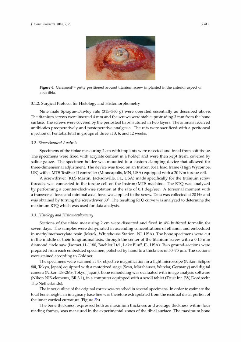
Twenty-four male Sprague-Dawley rats (315–360 g) were anesthetized with a peritoneal injectionof Pentobarbital (60 mg/mL) and Diazepam (5 mg/mL) in NaCl (0.15 M). In both hind legs, an incisionwas made in the proximal portion of the tibia and a periosteal flap was moved to the side. A hole witha depth of 5 mm ˆ 1.5 mm Ø was drilled 5 mm beneath the tibial proximal growth plate. With theaid of a 3 mm guider, a titanium screw (2 mm Ø ˆ 7 mm long, Ti-Cross drive screws, KLS Martin,Jacksonville, FL, USA) was screwed 3.5 mm into the bone in order to attain a uni-cortical anchoragewithout interference from the posterior cortical bone. After screw implantation, Cerament™ putty wasapplied around the screw on the tibial bone surface (Figure 6) in one randomly selected hind leg.
The operation field was kept dry to avoid blood contamination. The working time of the materialwas approximately 3 min and the setting time was 5 min. On the contra-lateral tibia, the titaniumscrew was left without Cerament™. Subsequently, the periosteal flaps were sutured in two layers.The animals received antibiotics preoperatively 0.05 mL Streptocilline® vet (250 mg/mL + 200 mg/mL;Boehringer, Ingelheim, Germany) and postoperative analgesia 0.15 mL Temgesic® (1:10; 0.3 mg/mL;Schering-Plough, Kenilworth, NJ, USA). The rats were sacrificed in groups of eight after 1 day, and6 and 12 weeks.
J. Funct. Biomater. 2016, 7, 2 7 of 9
J. Funct. Biomater. 2016, 7, 2
7
Figure 6. Cerament™ putty positioned around titanium screw implanted in the anterior aspect of a
rat tibia.
3.1.2. Surgical Protocol for Histology and Histomorphometry
Nine male Sprague‐Dawley rats (315–360 g) were operated essentially as described above. The
titanium screws were inserted 4 mm and the screws were stable, protruding 3 mm from the bone
surface. The screws were covered by the periosteal flaps, sutured in two layers. The animals received
antibiotics preoperatively and postoperative analgesia. The rats were sacrificed with a peritoneal
injection of Pentobarbital in groups of three at 3, 6, and 12 weeks.
3.2. Biomechanical Analysis
Specimens of the tibiae measuring 2 cm with implants were resected and freed from soft tissue.
The specimens were fixed with acrylate cement in a holder and were then kept fresh, covered by
saline gauze. The specimen holder was mounted in a custom clamping device that allowed for
three‐dimensional adjustment. The device was fixed on an Instron 8511 load frame (High Wycombe,
UK) with a MTS TestStar II controller (Minneapolis, MN, USA) equipped with a 20 Nm torque cell.
A screwdriver (KLS Martin, Jacksonville, FL, USA) made specifically for the titanium screw
threads, was connected to the torque cell on the Instron/MTS machine. The RTQ was analyzed by
performing a counter‐clockwise rotation at the rate of 0.1 deg/sec. A torsional moment with a
transversal force and minimal axial force was applied to the screw. Data was collected at 20 Hz and
was obtained by turning the screwdriver 30°. The resulting RTQ curve was analyzed to determine
the maximum RTQ which was used for data analysis.
3.3. Histology and Histomorphometry
Sections of the tibiae measuring 2 cm were dissected and fixed in 4% buffered formalin for seven
days. The samples were dehydrated in ascending concentrations of ethanol, and embedded in
methylmethacrylate resin (Merck, Whitehouse Station, NJ, USA). The bone specimens were cut in the
middle of their longitudinal axis, through the center of the titanium screw with a 0.15 mm diamond
circle saw (Isomet 11‐1180, Buehler Ltd., Lake Bluff, IL, USA). Two ground‐sections were prepared
from each embedded specimen, polished by hand to a thickness of 50–75 μm. The sections were
stained according to Goldner.
The specimens were scanned at 4× objective magnification in a light microscope (Nikon Eclipse
80i, Tokyo, Japan) equipped with a motorized stage (Scan, Märzhäuser, Wetzlar, Germany) and
digital camera (Nikon DS‐2Mv, Tokyo, Japan). Bone remodeling was evaluated with image analysis
software (Nikon NIS‐elements, BR 3.1), in a computer equipped with a scroll tablet (Trust Int. BV,
Dordrecht, The Netherlands).
The inner outline of the original cortex was resorbed in several specimens. In order to estimate
the total bone height, an imaginary base line was therefore extrapolated from the residual distal
portion of the inner cortical curvature (Figure 3b).
Figure 6. Cerament™ putty positioned around titanium screw implanted in the anterior aspect ofa rat tibia.
3.1.2. Surgical Protocol for Histology and Histomorphometry
Nine male Sprague-Dawley rats (315–360 g) were operated essentially as described above.The titanium screws were inserted 4 mm and the screws were stable, protruding 3 mm from the bonesurface. The screws were covered by the periosteal flaps, sutured in two layers. The animals receivedantibiotics preoperatively and postoperative analgesia. The rats were sacrificed with a peritonealinjection of Pentobarbital in groups of three at 3, 6, and 12 weeks.
3.2. Biomechanical Analysis
Specimens of the tibiae measuring 2 cm with implants were resected and freed from soft tissue.The specimens were fixed with acrylate cement in a holder and were then kept fresh, covered bysaline gauze. The specimen holder was mounted in a custom clamping device that allowed forthree-dimensional adjustment. The device was fixed on an Instron 8511 load frame (High Wycombe,UK) with a MTS TestStar II controller (Minneapolis, MN, USA) equipped with a 20 Nm torque cell.
A screwdriver (KLS Martin, Jacksonville, FL, USA) made specifically for the titanium screwthreads, was connected to the torque cell on the Instron/MTS machine. The RTQ was analyzedby performing a counter-clockwise rotation at the rate of 0.1 deg/sec. A torsional moment witha transversal force and minimal axial force was applied to the screw. Data was collected at 20 Hz andwas obtained by turning the screwdriver 30˝. The resulting RTQ curve was analyzed to determine themaximum RTQ which was used for data analysis.
3.3. Histology and Histomorphometry
Sections of the tibiae measuring 2 cm were dissected and fixed in 4% buffered formalin forseven days. The samples were dehydrated in ascending concentrations of ethanol, and embeddedin methylmethacrylate resin (Merck, Whitehouse Station, NJ, USA). The bone specimens were cutin the middle of their longitudinal axis, through the center of the titanium screw with a 0.15 mmdiamond circle saw (Isomet 11-1180, Buehler Ltd., Lake Bluff, IL, USA). Two ground-sections wereprepared from each embedded specimen, polished by hand to a thickness of 50–75 µm. The sectionswere stained according to Goldner.
The specimens were scanned at 4ˆ objective magnification in a light microscope (Nikon Eclipse80i, Tokyo, Japan) equipped with a motorized stage (Scan, Märzhäuser, Wetzlar, Germany) and digitalcamera (Nikon DS-2Mv, Tokyo, Japan). Bone remodeling was evaluated with image analysis software(Nikon NIS-elements, BR 3.1), in a computer equipped with a scroll tablet (Trust Int. BV, Dordrecht,The Netherlands).
The inner outline of the original cortex was resorbed in several specimens. In order to estimate thetotal bone height, an imaginary base line was therefore extrapolated from the residual distal portion ofthe inner cortical curvature (Figure 3b).
The bone thickness, expressed both as maximum thickness and average thickness within fourreading frames, was measured in the experimental zones of the tibial surface. The maximum bone

J. Funct. Biomater. 2016, 7, 2 8 of 9
thickness was measured in two horizontal measuring zones of approximately 3000 µm proximally anddistally to the titanium screw.
The average thickness from the inner cortical surface, or the imaginary base curvature, wasmeasured in four frames (A–D), approx. 540 µm wide (Figure 3a).
The procedure was repeated by the same observer three times at separate occasions and the resultwas expressed as the mean value of the three observations. The average height of the bone in eachframe was calculated as:
average bone height f rame “f rame area
f rame width(1)
3.4. Statistical Analysis
A statistical computer software program (SPSS) was used to perform Kruskal-Wallis,Jonckheere-Terpstra, and Wilcoxon’s signed ranks tests. Data is given as mean ˘ standard deviation.
4. Conclusions
In conclusion, Cerament™ is capable of conducting bone growth from a cortical bone surfaceand also to help maintain the augmented bone. However, the newly formed bone in this applicationdoes not significantly add to the osseointegrative strength of the implant screw, as measured by torqueresistance, during the first 12 weeks.
Author Contributions: All authors conceived and designed the experiments; Anna Truedsson andJian-Sheng Wang performed the experiments; Anna Truedsson, Jian-Sheng Wang and Gunnar Warfvinge analyzedthe data; Jian-Sheng Wang and Pia Lindberg contributed reagents/materials/analysis tools; Anna Truedsson,Jian-Sheng Wang and Gunnar Warfvinge wrote the paper.
Conflicts of Interest: The authors declare no conflict of interest.
References
1. Van den Bergh, J.P.; ten Bruggenkate, C.M.; Disch, F.J.; Tuinzing, D.B. Anatomical aspects of sinus floorelevations. Clin. Oral Implants Res. 2000, 11, 256–265. [CrossRef] [PubMed]
2. Block, M.S.; Kent, J.N. Sinus augmentation for dental implants: The use of autogenous bone. J. OralMaxillofac. Surg. 1997, 55, 1281–1286. [CrossRef]
3. Younger, E.M.; Chapman, M.W. Morbidity at bone graft donor sites. J. Orthop. Trauma 1989, 3, 192–195.[CrossRef] [PubMed]
4. Goulet, J.A.; Senunas, L.E.; DeSilva, G.L.; Greenfield, M.L. Autogenous iliac crest bone graft. Complicationsand functional assessment. Clin. Orthop. Relat. Res. 1997, 199, 76–81. [CrossRef]
5. De Leonardis, D.; Pecora, G.E. Prospective study on the augmentation of the maxillary sinus with calciumsulfate: Histological results. J. Periodontol. 2000, 71, 940–947. [CrossRef] [PubMed]
6. Hallman, M.; Sennerby, L.; Zetterqvist, L.; Lundgren, S. A 3-year prospective follow-up study ofimplant-supported fixed prostheses in patients subjected to maxillary sinus floor augmentation with a 80:20mixture of deproteinized bovine bone and autogenous bone Clinical, radiographic and resonance frequencyanalysis. Int. J. Oral Maxillofac. Surg. 2005, 34, 273–280. [PubMed]
7. Suba, Z.; Takacs, D.; Matusovits, D.; Barabas, J.; Fazekas, A.; Szabo, G. Maxillary sinus floor grafting withbeta-tricalcium phosphate in humans: Density and microarchitecture of the newly formed bone. Clin. OralImplants Res. 2006, 17, 102–108. [CrossRef] [PubMed]
8. Esposito, M.; Grusovin, M.G.; Worthington, H.V.; Coulthard, P. Interventions for replacing missing teeth:Bone augmentation techniques for dental implant treatment. Cochrane Database Syst. Rev. 2006. [CrossRef]
9. Bai, B.; Kummer, F.J.; Spivak, J. Augmentation of anterior vertebral body screw fixation by an injectable,biodegradable calcium phosphate bone substitute. Spine 2001, 26, 2679–2683. [CrossRef] [PubMed]
10. Taniwaki, Y.; Takemasa, R.; Tani, T.; Mizobuchi, H.; Yamamoto, H. Enhancement of pedicle screw stabilityusing calcium phosphate cement in osteoporotic vertebrae: In vivo biomechanical study. J. Orthop. Sci.2003, 8, 408–414. [CrossRef] [PubMed]

J. Funct. Biomater. 2016, 7, 2 9 of 9
11. De Riu, G.; de Riu, N.; Spano, G.; Pizzigallo, A.; Petrone, G.; Tullio, A. Histology and stability study ofcortical bone graft influence on titanium implants. Oral Surg. Oral Med. Oral Pathol. Oral Radiol. Endod.2007, 103, e1–e7. [CrossRef] [PubMed]
12. Rasmusson, L.; Meredith, N.; Kahnberg, K.E.; Sennerby, L. Stability assessments and histology of titaniumimplants placed simultaneously with autogenous onlay bone in the rabbit tibia. Int. J. Oral Maxillofac. Surg.1998, 27, 229–235. [CrossRef]
13. Kohal, R.J.; Mellas, P.; Hurzeler, M.B.; Trejo, P.M.; Morrison, E.; Caffesse, R.G. The effects of guided boneregeneration and grafting on implants placed into immediate extraction sockets. An experimental study indogs. J. Periodontol. 1998, 69, 927–937. [CrossRef] [PubMed]
14. Gotfredsen, K.; Nimb, L.; Hjorting-Hansen, E.; Jensen, J.S.; Holmen, A. Histomorphometric and removaltorque analysis for TiO2-blasted titanium implants. An experimental study on dogs. Clin. Oral Implants Res.1992, 3, 77–84. [CrossRef] [PubMed]
15. Hulshoff, J.E.; Hayakawa, T.; van Dijk, K.; Leijdekkers-Govers, A.F.; van der Waerden, J.P.; Jansen, J.A.Mechanical and histologic evaluation of Ca-P plasma-spray and magnetron sputter-coated implants intrabecular bone of the goat. J. Biomed. Mater. Res. 1997, 36, 75–83. [CrossRef]
16. Han, C.H.; Johansson, C.B.; Wennerberg, A.; Albrektsson, T. Quantitative and qualitative investigations ofsurface enlarged titanium and titanium alloy implants. Clin. Oral Implants Res. 1998, 9, 1–10. [CrossRef][PubMed]
17. Marcia, S.; Boi, C.; Dragani, M.; Marini, S.; Marras, M.; Piras, E.; Anselmetti, G.C.; Masala, S. Effectivenessof a bone substitute (CERAMENT™) as an alternative to PMMA in percutaneous vertebroplasty: 1-yearfollow-up on clinical outcome. Eur. Spine J. 2012, 21, S112–S118. [CrossRef] [PubMed]
18. Nilsson, M.; Wang, J.S.; Wielanek, L.; Tanner, K.E.; Lidgren, L. Biodegradation and biocompatability ofa calcium sulphate-hydroxyapatite bone substitute. J. Bone Joint Surg. Br. 2004, 86, 120–125. [PubMed]
19. Peltier, L.F. The use of plaster of Paris to fill defects in bone. Clin. Orthop. 1961, 21, 1–31. [CrossRef]20. Stubbs, D.; Deakin, M.; Chapman-Sheath, P.; Bruce, W.; Debes, J.; Gillies, R.M.; Walsh, W.R. In vivo evaluation
of resorbable bone graft substitutes in a rabbit tibial defect model. Biomaterials 2004, 25, 5037–5044. [CrossRef][PubMed]
21. Truedsson, A.; Wang, J.S.; Lindberg, P.; Gordh, M.; Sunzel, B.; Warfvinge, G. Bone substitute as an onlay grafton rat tibia. Clin. Oral Implants Res. 2010, 21, 424–429. [CrossRef] [PubMed]
22. Schierano, G.; Canuto, R.A.; Navone, R.; Peirone, B.; Martinasso, G.; Pagano, M.; Maggiora, M.; Manzella, C.;Easton, M.; Davit, A.; et al. Biological factors involved in the osseointegration of oral titanium implants withdifferent surfaces: A pilot study in minipigs. J. Periodontol. 2005, 76, 1710–1720. [CrossRef] [PubMed]
23. Horton, W.C.; Blackstock, S.F.; Norman, J.T.; Hill, C.S.; Feiertag, M.A.; Hutton, W.C. Strength of fixation ofanterior vertebral body screws. Spine 1996, 21, 439–444. [CrossRef] [PubMed]
24. Ivanoff, C.J.; Sennerby, L.; Lekholm, U. Influence of mono- and bicortical anchorage on the integration oftitanium implants. A study in the rabbit tibia. Int. J. Oral Maxillofac. Surg. 1996, 25, 229–235. [CrossRef]
25. Albrektsson, T.; Johansson, C. Osteoinduction, osteoconduction and osseointegration. Eur. Spine J. 2001, 10,S96–S101. [PubMed]
26. Zampelis, V.; Tagil, M.; Lidgren, L.; Isaksson, H.; Atroshi, I.; Wang, J.S. The effect of a biphasic injectablebone substitute on the interface strength in a rabbit knee prosthesis model. J. Orthop. Surg. Res. 2013, 8.[CrossRef] [PubMed]
27. Stenlund, P.; Murase, K.; Stalhandske, C.; Lausmaa, J.; Palmquist, A. Understanding mechanisms and factorsrelated to implant fixation; a model study of removal torque. J. Mech. Behav. Biomed. Mater. 2014, 34, 83–92.[CrossRef] [PubMed]
28. Wennerberg, A.; Albrektsson, T.; Lausmaa, J. Torque and histomorphometric evaluation of c.p. titaniumscrews blasted with 25- and 75-microns-sized particles of Al2O3. J. Biomed. Mater. Res. 1996, 30, 251–260.[CrossRef]
© 2016 by the authors; licensee MDPI, Basel, Switzerland. This article is an open accessarticle distributed under the terms and conditions of the Creative Commons by Attribution(CC-BY) license (http://creativecommons.org/licenses/by/4.0/).