otdrs bi-directional · pdf filesome relevant optical terms otdr (optical time domain...
TRANSCRIPT

OTDRs … Bi-Directional Testing

OTDRs … Bi-Directional Testing
… Done Correctly
OTDRs … Bi-Directional Testing
Presenter Chuck Dykstra, Canadian Product Manager

Some Relevant Optical Terms OTDR (Optical Time Domain Reflectometer) … It injects a series of optical pulses into the fiber under test and extracts, from the same end of the fiber, light that is scattered (Rayleigh backscatter) or reflected back from points along the fiber. Backscatter … is used to infer loss based on drops in the strength of the reflected signal. If (Rayleigh) Backscatter did not occur, then an OTDR would never have been designed. Reflective Event … When light traveling through glass (fiber optic cable) encounters a different density material like Air, up to 8% of the light is reflected back to the source, while the rest continues out of the glass. This is called Fresnel Reflection. Fresnel Reflection allows us to see where connectors are. Almost always a connector. Caused by a change in refractive index. Could be a poor mechanical splice too, though rare.

Some Relevant Optical Terms Launch Fiber … Easy answer is “used because I want to be able to see and measure the first connection in the link.” Tail Fiber … Easy answer is “used because I want to be able to see and measure the last connection in the link. Launch Compensation … Used so the measurement of the Launch and Receive cables are not included in the reports. Non-Reflective Event … An event that is “non-reflective”, and is indicated by a drop in the strength of the backscatter signal. Almost always a splice

Some Relevant Optical Terms Hidden Event … Where two connectors are close enough to each other to be within the event dead zone of the OTDR.
Ghost … False events that look like reflective events, but have no loss. Can be very confusing to the technician, since they seem to be real reflective events, like connectors. They are caused by the OTDR pulse traveling through a highly reflective connection. Then, when the next event reflection hits the highly reflective connection the light begins to bounce back a forth until it is attenuated to the noise level. Ghosts are typically caused by connectors with poor reflectance (ie. poorly polished). Multi-mode reflectance should be less than -35 dB. Most ghosts appear after the end of the link.

Some Relevant Optical Terms Pulse Width … To ensure backscatter is returned to the OTDR from long distances, the tester has to turn the light on for a longer period of time. This increase in time the light is “on” is created by increasing the pulse width. The longer the pulse width the larger the “dead zone”. Dead Zone … The minimum distance required, after a reflective event, for the OTDR to detect an event – but not measure it. Insertion Loss … The loss of signal power resulting from the insertion of a device in a transmission line or optical fiber and is usually expressed in decibels

Why do Bidirectional Testing with OTDRs?
• Differences in coefficient of backscatter between launch fibers, receive fibers, Loop-Back fibers, in patch cords and permanent link, and in two different fiber cores being fused together … cause false loss, and false gain issues with OTDRs.

Why do Bidirectional Testing with OTDRs?
• Differences in coefficient of backscatter between launch fibers, receive fibers, Loop-Back fibers, in patch cords and permanent link, and in two different fiber cores being fused together … cause false loss, and false gain issues with OTDRs.
• Here’s Why … o In this example the backscatter is consistent between the 2 fibers and the OTDR
reports the event loss correctly.

Why do Bidirectional Testing with OTDRs?
• Differences in coefficient of backscatter between launch fibers, receive fibers, Loop-Back fibers, in patch cords and permanent link, and in two different fiber cores being fused together … cause false loss, and false gain issues with OTDRs.
• Here’s Why … o In this example, the attached fiber (on the right) has ‘less’ attenuation then the
fiber on the left. The percentage of light from the OTDR test pulse will go down. The measured loss on the OTDR will include the actual loss plus a loss error caused by the lower backscatter level.
o The OTDR will report ‘more’ loss then there actually is. This can result in a ‘false failure’.
Why do Bidirectional Testing with OTDRs?
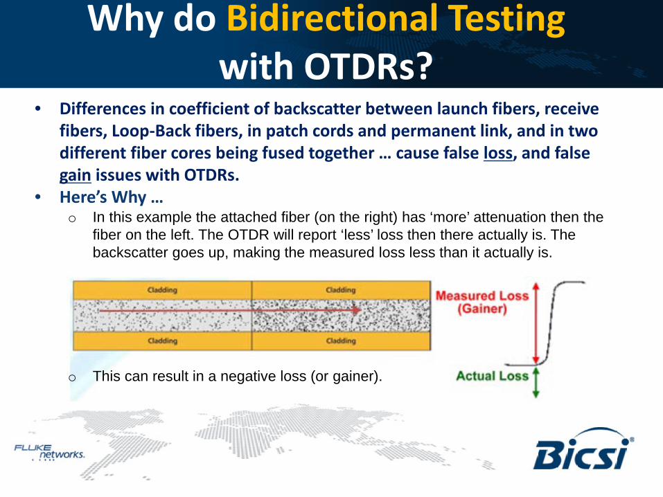
• Differences in coefficient of backscatter between launch fibers, receive fibers, Loop-Back fibers, in patch cords and permanent link, and in two different fiber cores being fused together … cause false loss, and false gain issues with OTDRs.
• Here’s Why … o In this example the attached fiber (on the right) has ‘more’ attenuation then the
fiber on the left. The OTDR will report ‘less’ loss then there actually is. The backscatter goes up, making the measured loss less than it actually is.
o This can result in a negative loss (or gainer).

Why do Bidirectional Testing with OTDRs?
• Differences in coefficient of backscatter between launch fibers, receive fibers, Loop-Back fibers, in patch cords and permanent link, and in two different fiber cores being fused together … cause false loss, and false gain issues with OTDRs.
• Standards now require it … ANSI/TIA-526-14-B and IEC 61280-4-1 o “Bi-directional testing is required if the fiber characteristics of the test cords
differ from those of the cable under test” o “ … if it is required to measure accurately the insertion loss of individual
connector interfaces or other events in the cabling, then bi-directional OTDR testing is required” (Insertion Loss … The loss of signal power resulting from the insertion of a device in a transmission
line or optical fiber)

Why do Bidirectional Testing with OTDRs?
• Differences in coefficient of backscatter between launch fibers, receive fibers, Loop-Back fibers, in patch cords and permanent link, and in two different fiber cores being fused together … cause false loss, and false gain issues with OTDRs.
• Standards now require it … ANSI/TIA-526-14-B and IEC 61280-4-1 o “Bi-directional testing is required if the fiber characteristics of the test cords
differ from those of the cable under test” o “ … if it is required to measure accurately the insertion loss of individual
connector interfaces or other events in the cabling, then bi-directional OTDR testing is required”
Launch Fiber Fiber Under Test Tail Fiber
OTDR Testing According to the Standards
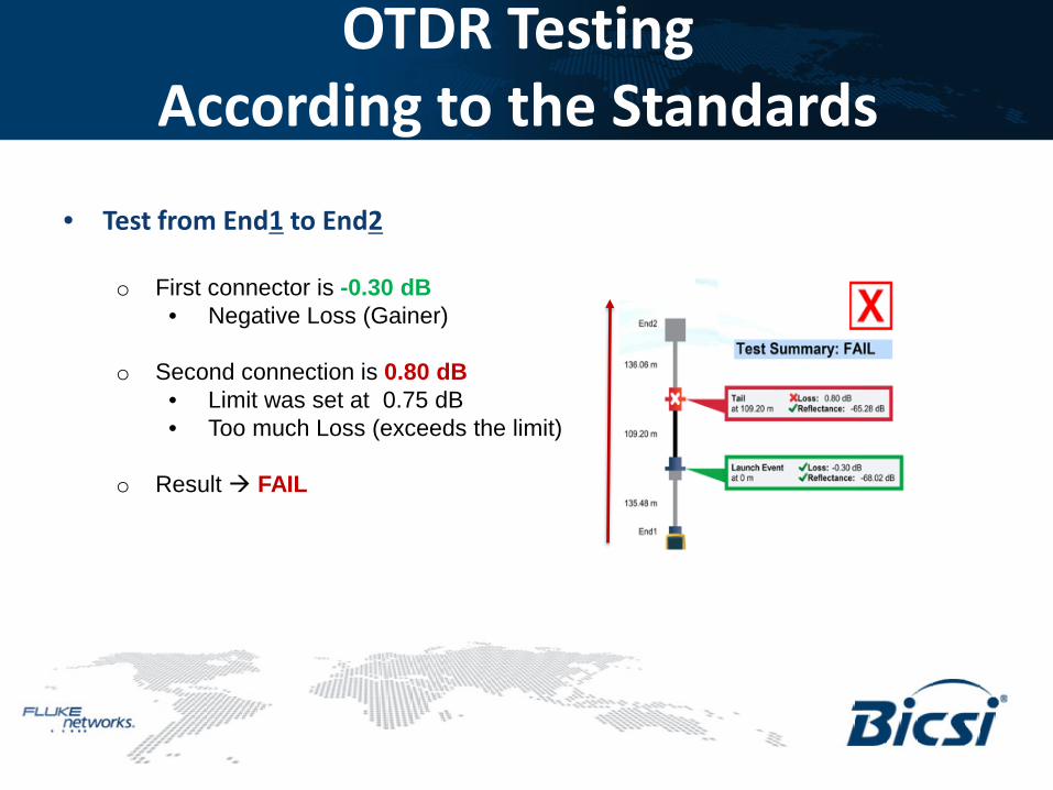
• Test from End1 to End2 o First connector is -0.30 dB
• Negative Loss (Gainer)
o Second connection is 0.80 dB • Limit was set at 0.75 dB • Too much Loss (exceeds the limit)
o Result FAIL

OTDR Testing According to the Standards
• Test from End2 to End1 o Second connector is now -0.37 dB
• It was 0.8 dB
o First connection is now 0.90 dB • A Fail (limit set at 0.75 dB) • It was -0.30 dB (Gainer)
o Losses are now reversed from
‘End1 to End2’ test
o Result FAIL

OTDR Testing According to the Standards
• So … Which Test is Correct?

OTDR Testing According to the Standards
• So … Which Test is Correct?
• What happens when we Average the two Results?

OTDR Testing According to the Standards
• So … Which Test is Correct? o Averaging out the tests results
• First connection of 0.30 dB ((-0.30 dB) + (0.90dB) / 2 0.30 dB
• Second connection of 0.22 dB (0.80 dB + (-0.37 dB)) / 2 0.215 dB
o Link now Passes o Result PASS
• What happens when we Average the two Results?
1st
2nd

OTDR Testing According to the Standards
• Here’s the issue … In order to accurately measure the first and last connection for bi-directional “averaging”, one needs to keep the launch and tail cords in their initial measurement positions.
• According to the standards, they cannot be disconnected.
OTDR Testing According to the Standards
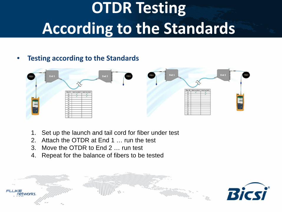
• Testing according to the Standards
1. Set up the launch and tail cord for fiber under test 2. Attach the OTDR at End 1 … run the test 3. Move the OTDR to End 2 … run test 4. Repeat for the balance of fibers to be tested

OTDR Testing According to the Standards
• Why most People Don’t test to the Standards
Walking the tester to the far end each time is not popular, so most people just don’t do it. From a technician’s point of view, it’s not practical.
OTDR Testing According to the Standards
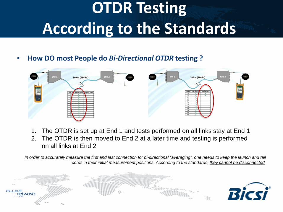
• How DO most People do Bi-Directional OTDR testing ?
1. The OTDR is set up at End 1 and tests performed on all links stay at End 1 2. The OTDR is then moved to End 2 at a later time and testing is performed
on all links at End 2
In order to accurately measure the first and last connection for bi-directional “averaging”, one needs to keep the launch and tail cords in their initial measurement positions. According to the standards, they cannot be disconnected.

OTDR Testing According to the Standards
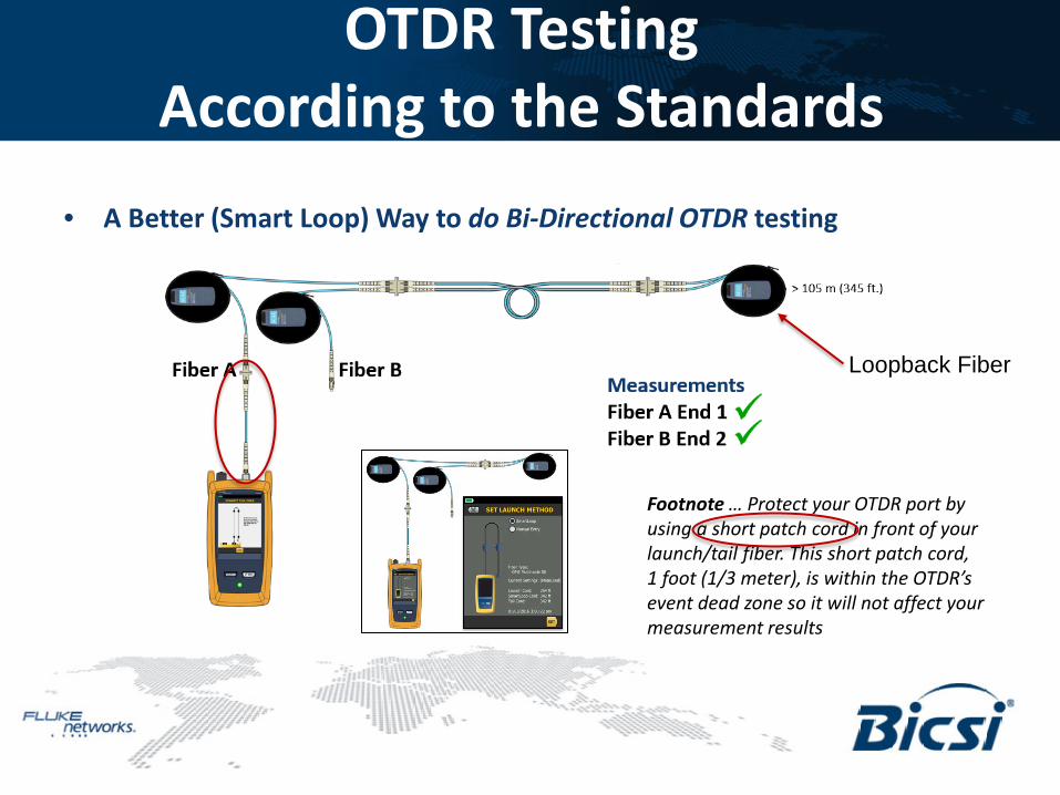
• A Better (Smart Loop) Way to do Bi-Directional OTDR testing
Loopback Fiber
OTDR Testing According to the Standards
• A Better (Smart Loop) Way to do Bi-Directional OTDR testing
Loopback Fiber
Footnote … Protect your OTDR port by using a short patch cord in front of your launch/tail fiber. This short patch cord, 1 foot (1/3 meter), is within the OTDR’s event dead zone so it will not affect your measurement results

OTDR Testing According to the Standards
• A Better (Smart Loop) Way to do Bi-Directional OTDR testing
Loopback Fiber

OTDR Testing According to the Standards
• How does SmartLoop Work? 1. Set Launch Compensation (SmartLoop)
Three Cords

OTDR Testing According to the Standards
• How does SmartLoop Work? 1. Set Launch Compensation (SmartLoop) 2. Inspect the Link (ensure ends are still clean) 3. Connect to Fiber A and run the Test

OTDR Testing According to the Standards
• How does SmartLoop Work? 1. Set Launch Compensation (SmartLoop) 2. Inspect the Link (ensure ends are still clean) 3. Connect to Fiber A and run the Test

OTDR Testing According to the Standards
• How does SmartLoop Work? 1. Set Launch Compensation (SmartLoop) 2. Inspect the Link (ensure ends are still clean) 3. Connect to Fiber A and run the Test 4. Connect to Fiber B and complete
the test

OTDR Testing According to the Standards
• How does SmartLoop Work? 1. Measure both fibers (A & B) from End 1 2. Cut into two 3. Gives two OTDR traces

OTDR Testing According to the Standards
• How does SmartLoop Work? 1. Measure both fibers (A & B) from End 1 2. Cut into two 3. Gives two OTDR traces

OTDR Testing According to the Standards
• How does SmartLoop Work? o You now have:
1. Fiber A measured from End 1 2. Fiber A measured from End 2 3. Fiber B measured from End 1 4. Fiber B measured from End 2 5. Fiber A “bi-directionally” averaged 6. Fiber B “bi-directionally” averaged
… All from testing at the Same End with one OTDR … and … with the launch and tail cords in their initial measurement positions
End 1 End 2

OTDR Testing According to the Standards
• SmartLoop applies Bi-Directional Averaging for you o Using SmartLoop, OptiFiber Pro will automatically calculate the average of the
two traces – you no longer have to manually average End 1 and End 2 to see what the actual performance of the link is
o Launch and Tail fibers are not disconnected o Only ONE OTDR is required
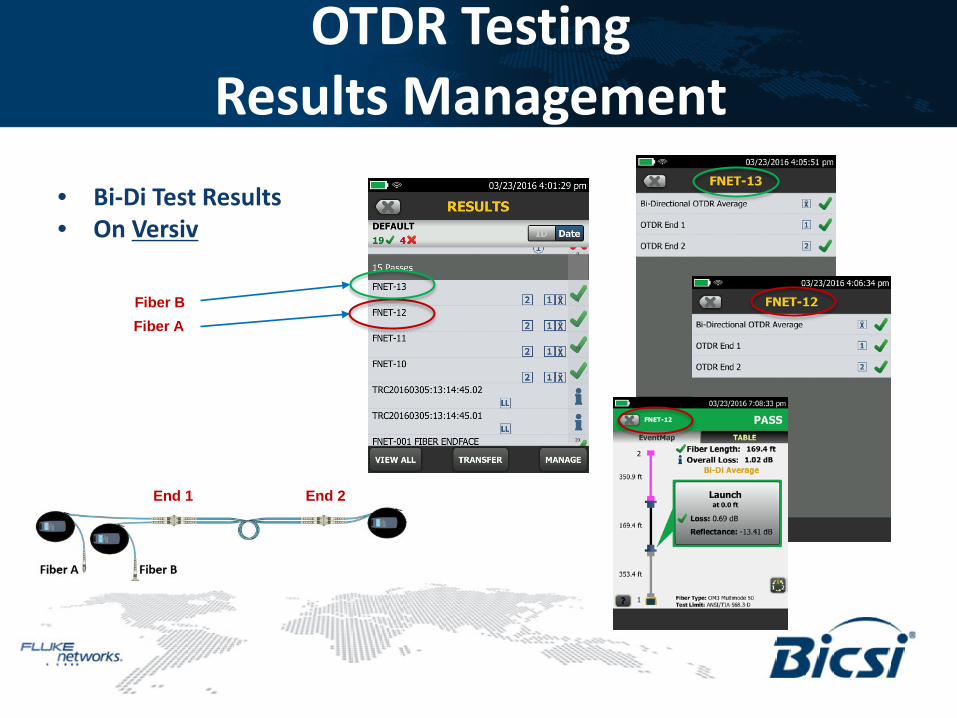
OTDR Testing Results Management
• Bi-Di Test Results • On Versiv
End 1 End 2
Fiber A Fiber B

OTDR Testing Results Management
• Bi-Di Test Results • LinkWare Reports
End 1 End 2
Fiber A
Fiber B

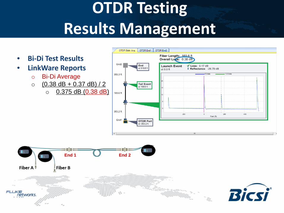
OTDR Testing Results Management
• Bi-Di Test Results • LinkWare Reports
o From End 1 (0.38 dB)
End 1 End 2
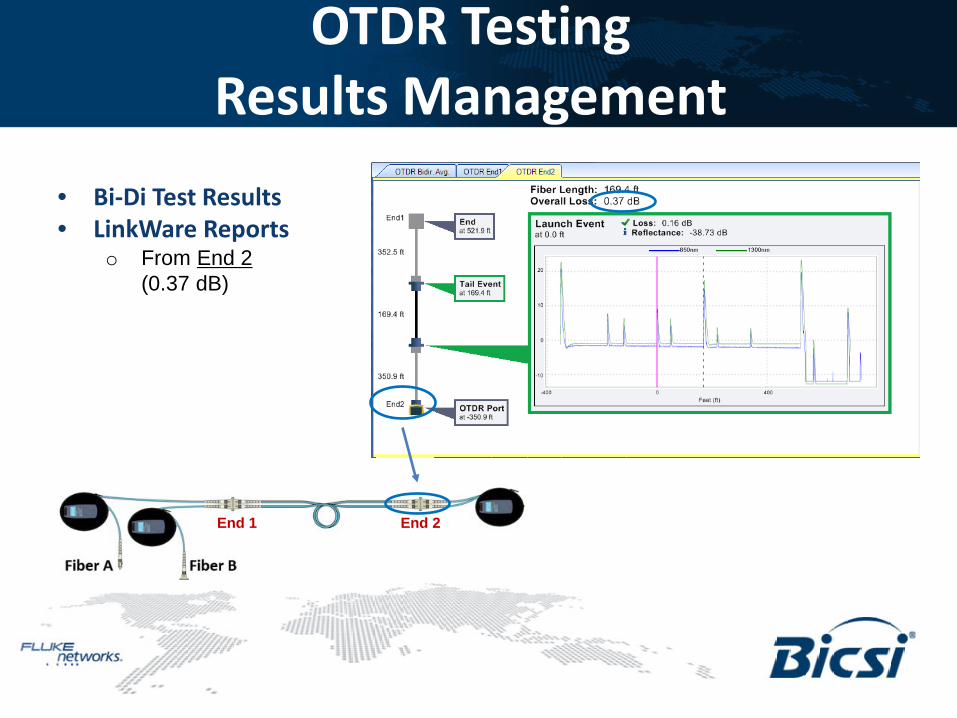
OTDR Testing Results Management
• Bi-Di Test Results • LinkWare Reports
o From End 2 (0.37 dB)
End 1 End 2
OTDR Testing Results Management
• Bi-Di Test Results • LinkWare Reports
o Bi-Di Average o (0.38 dB + 0.37 dB) / 2
o 0.375 dB (0.38 dB)
End 1 End 2
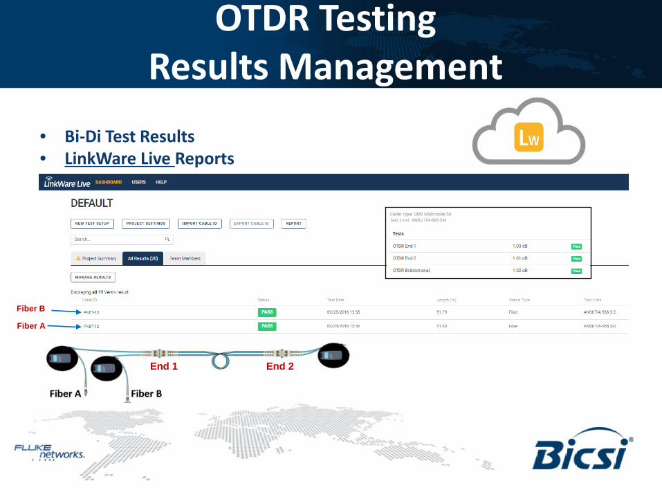
OTDR Testing Results Management
• Bi-Di Test Results • LinkWare Live Reports
End 1 End 2
Fiber A
Fiber B

OTDR Testing Bi-Directional Averaging
• Getting back now to the ‘standards’ and ANSI/TIA-526-14-B and IEC 61280-4-1 o “Bi-directional testing is required if the fiber characteristics of the test cords differ
from those of the cable under test” o “ … if it is required to measure accurately the insertion loss of individual
connector interfaces or other events in the cabling, then bi-directional OTDR testing is required”
• To ensure compliance to the standards, the OptiFiber PRO is able to provide on-board, bi-directional averaging and SmartLoop operation. This now allows for fully supported automated duplex fiber OTDR testing with twice the increase in productivity without the need to walk to the other end.
OTDR Testing Bi-Directional Averaging
Thank You