outdoor mesh wireless networks - institut teknologi bandungai3.itb.ac.id/~basuki/private/cisco wlan...
TRANSCRIPT

© 2012, Cisco Systems, Inc. All rights reserved.
Presentation_ID.scr
1
BRKEWN-2027
Design and Deployment of Outdoor Mesh Wireless Networks
© 2012 Cisco and/or its affiliates. All rights reserved. Cisco PublicPresentation_ID 2
Abstract
This intermediate session will describe the Outdoor wireless productsinvolved in delivering outdoor broadband wireless services for ServiceProviders, Municipalities, Transportation and other end user customers.The Cisco Outdoor Wireless Bridging and MESH Technologies will bediscussed in detail.
The session is intended for wireless network architects, network designers, networkplanners working in Public Sector, Service Providers, Systems Integrators, smallproviders and enterprise customers. Attendees should have some basic knowledgein configuration of IP routers, Wi-Fi access points, and Radio Frequency planning.Basic understanding of the Controller Architecture is required.

© 2012, Cisco Systems, Inc. All rights reserved.
Presentation_ID.scr
2
© 2012 Cisco and/or its affiliates. All rights reserved. Cisco PublicPresentation_ID 3
Agenda
Cisco Outdoor Mesh architecture overview
- From bridging to Mesh
- Cisco Outdoor Mesh architecture components
- Bringing Wi-Fi innovation to outdoors
How to deploy an outdoor wireless network
- Standard and normative
- Design & Planning
- Site Survey and Deployment
Cisco Outdoor Mesh architecture overview

© 2012, Cisco Systems, Inc. All rights reserved.
Presentation_ID.scr
3
© 2012 Cisco and/or its affiliates. All rights reserved. Cisco PublicPresentation_ID 5
Internet
Point To Point
L3/L2 switch
L2 switch5GHz/2.4 GHz
Bridging: basic LAN to LAN wireless connectivity
Point To Multipoint
L2 switch
Cisco Outdoor Mesh architecture overview
Bridging
© 2012 Cisco and/or its affiliates. All rights reserved. Cisco PublicPresentation_ID 6
Controller
L3/L2 switch
Mesh Deployment Flexibility:
LAN-to-LAN connectivity
Multiple hop backhaul
2.4 GHz and 5GHz wireless client access
Ethernet Access to wired clients
LAN-to-LAN in motion with Work Group Bridge (WGB)
2.4 GHz Access
5 GHz Access
MAP(Mesh AP)
RAP(Root AP) Backhaul 5GHz
MAP
Backhaul 5GHz
WGB
5 GHz Access
Wired access
L2 switch
Cisco Outdoor Mesh architecture overview
From Bridging to Mesh

© 2012, Cisco Systems, Inc. All rights reserved.
Presentation_ID.scr
4
© 2012 Cisco and/or its affiliates. All rights reserved. Cisco PublicPresentation_ID 7
Controller
MAP
Parent
Neighbor Optimal parent selection selects the
path “ease” across each available backhaul
Ease based on number of hops and link SNR (Signal Noise Ratio)
AWPP uses a “Parent Stickiness” value to mitigate Route Flaps
AWPP integrates 802.11h DFS (Dynamic Frequency Selection) for radar detection and avoidance
From release 7.0.116 preferred parent can be configured
Adaptive Wireless Path Protocol (AWPP)
establishes the best path to the Root
RAP
Cisco Outdoor Mesh architecture overview
Self-configuring, self-healing Mesh
© 2012 Cisco and/or its affiliates. All rights reserved. Cisco PublicPresentation_ID 8
WLAN
Controller
CAPWAP in
mesh header
Ethernet in
mesh header
Wireless client traffic
Wired client traffic
RAP
MAP
MAPs dynamically
build a tree with
the best path to
the RAP
Intranet
Mesh carries two types of traffic:
CAPWAP traffic
Mesh header
Cisco Outdoor Mesh architecture overview
Deployment flexibility

© 2012, Cisco Systems, Inc. All rights reserved.
Presentation_ID.scr
5
© 2012 Cisco and/or its affiliates. All rights reserved. Cisco PublicPresentation_ID 9
Management
NCS manages up to 15000 APs
Controller
Up to 72 Controllers can be part of an N+1 or N+N+1 cluster
Dynamic RF optimization on access link for additional radios
Access Point
32 MAPs per RAP (20 recommended)
8 Hops (4 recommended)
16 SSIDs per AP (512 at WLC)
More RAPs for sector capacity
Intranet
Cisco Outdoor Mesh architecture overview
Scalability at different layers
© 2012 Cisco and/or its affiliates. All rights reserved. Cisco PublicPresentation_ID 10
WiSM
VLAN =2
AP-10
AP-22
MAC SSID AP WLAN WLC VLAN IP
AA-AA OpenWiFi 10 2 A 2 10.10.10.2
AP-47
Tunnel EoIPB to A
WLC-A
WLC-B
2247 B-A
Intra-controller RoamingInter-controller L3 Roaming
AA-AA
Cisco Outdoor Mesh architecture overview
Seamless user mobility
© 2012, Cisco Systems, Inc. All rights reserved.
Presentation_ID.scr
6
© 2012 Cisco and/or its affiliates. All rights reserved. Cisco PublicPresentation_ID 11
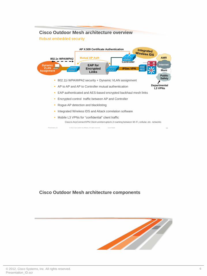
Dynamic VLAN
Assignment
802.11i WPA/WPA2 security + Dynamic VLAN assignment
AP to AP and AP to Controller mutual authentication
EAP authenticated and AES-based encrypted backhaul mesh links
Encrypted control traffic between AP and Controller
Rogue AP detection and blacklisting
Integrated Wireless IDS and Attack correlation software
Mobile L3 VPNs for “confidential” client traffic
Cisco’s AnyConnectVPN Client uninterrupted L3 roaming between Wi-Fi, cellular, etc. networks
Controller
IPSec VPN
EAP for Encrypted
Links
AP X.509 Certificate Authentication
802.1x WPA/WPA2 Mutual AP Auth
SiSi
Public Safety
Internet
Muni
AMR
Departmental L3 VPNs
Cisco Outdoor Mesh architecture overview
Robust embedded security
Cisco Outdoor Mesh architecture components

© 2012, Cisco Systems, Inc. All rights reserved.
Presentation_ID.scr
7
© 2012 Cisco and/or its affiliates. All rights reserved. Cisco PublicPresentation_ID 13
Stadium / Large Venue
Metro Wi-Fi
WLAN Controller
(WLC)
IP
Backhaul
Residential CPE
Client
Mesh
Network
Mobility Service Engine
(MSE)
CleanAIr – Spectrum
Intelligence
Advanced
Wireless IPS
Context Aware
Access Points:
- 802.11abgn
- CleanAIr, ClientLink, etc.
- Outdoor enclosure, AC/DC power; PoE capable. Battery backup
- POE port for peripheral devices
Wireless LAN Controller (WLC):
- Handles RF algorithms and optimization
- Seamless WiFi L3 mobility
- Provides security at each Layer
- Image and configuration Management
Prime NCS
- Network-wide policy configuration and device management
- Design and deployment tools
- Monitoring and troubleshooting
Mobility Service Engine (MSE)
- Enables Mobility services (WIPS, Context aware)
Root AP
(RAP)
Mesht AP
(MAP)
Cisco Wireless Outdoor Architecture components
Indoor Hotspot
NetworkControl System
(NCS)
© 2012 Cisco and/or its affiliates. All rights reserved. Cisco PublicPresentation_ID 14
Internet
3G/4G Macro Site
Stadium / Large Venue
Indoor Hotspot
Metro Wi-Fi
Partner Net
IP Core
UCS
WLAN Controller
(WLC)
IP
Backhaul
Cisco
ASR 5000
MSP
Credentials
Residential CPE
Client
AAA Captive
PortalNCSDHCP PCRFSvcs
Reporting
ISG
Mesh
Network
Cisco SP Wifi solution
NetworkControl System
(NCS)
Indoor Hotspot
End to end solution
© 2012, Cisco Systems, Inc. All rights reserved.
Presentation_ID.scr
8
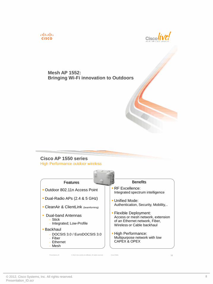
Mesh AP 1552:Bringing Wi-Fi innovation to Outdoors
© 2012 Cisco and/or its affiliates. All rights reserved. Cisco PublicPresentation_ID 16
High Performance outdoor wireless
Features
Outdoor 802.11n Access Point
Dual-Radio APs (2.4 & 5 GHz)
CleanAir & ClientLink (beamforming)
Dual-band Antennas- Stick- Integrated; Low-Profile
Backhaul
- DOCSIS 3.0 / EuroDOCSIS 3.0- Fiber- Ethernet- Mesh
Benefits
RF Excellence:Integrated spectrum intelligence
Unified Mode:Authentication, Security, Mobility,..
Flexible Deployment:Access or mesh network, extension of an Ethernet network, Fiber,
Wireless or Cable backhaul
High Performance:Multipurpose network with low CAPEX & OPEX
Cisco AP 1550 series

© 2012, Cisco Systems, Inc. All rights reserved.
Presentation_ID.scr
9
© 2012 Cisco and/or its affiliates. All rights reserved. Cisco PublicPresentation_ID 17
Beam Forming Spatial MultiplexingMaximal Ratio Combining
MIMO (Multiple Input, Multiple Output)
MIMO 40MHz ChannelsPacket
Aggregation
Backward
Compatibility
Performed by
Transmitter
(Talk Better)
Ensures Signal
Received in
Phase
Increases
Receive
Sensitivity
Works with
non-MIMO
Clients
Without Beam Forming Transmissions Arrive out of
Phase and signal is weaker
With Beam Forming Transmissions Arrive in Phase,
Increasing Signal Strength
Beam Forming gives a gain of 4+ dB in DL
Aspects of 802.11n
© 2012 Cisco and/or its affiliates. All rights reserved. Cisco PublicPresentation_ID 18
Beam Forming is effective for downstream traffic (MRC for upstream)
Measureable advantages:
- Increased SNR at cell edges
- Increased downstream data rates at cell edges
- Increased downstream throughput at cell edges
ClientLink benefits the whole cell with an overall quality coverage increased
Beam Forming is performed in hardware and use both UDP and TCP traffic (no Bidirectional Traffic required)
Can beam form to up to 30 clients per AP
Applicable to legacy rates of 9, 12, 18 (added for outdoors) and 24, 36, 48, 54 Mbps
Beam
Forming
802.11a/g
802.11n
Essential facts
ClientLink (Beamforming)

© 2012, Cisco Systems, Inc. All rights reserved.
Presentation_ID.scr
10
© 2012 Cisco and/or its affiliates. All rights reserved. Cisco PublicPresentation_ID 19
Beam Forming Spatial MultiplexingMaximal Ratio Combining
MIMO (Multiple Input, Multiple Output)
Performed by
Receiver
(Hear Better)
Combines
Multiple Received
Signals
Increases
Receive
Sensitivity
Works with
non-MIMO and
MIMO Clients
Performance
Multiple Signals Sent;
One Signal Chosen
Without MRC
Multiple Signals Sent and Combined
at the Receiver Increasing Fidelity
With MRC
MIMO AP
MRC gives a gain of 4.7 dB in UL for all Data Rates
MRC Gain is added in Rx Sensitivity number
40MHz ChannelsPacket
Aggregation
Backward
Compatibility
Aspects of 802.11n
© 2012 Cisco and/or its affiliates. All rights reserved. Cisco PublicPresentation_ID 20
3 Antennas Rx Signals
Combined Effect (Adding all Rx Paths)
MRC effect on received signal

© 2012, Cisco Systems, Inc. All rights reserved.
Presentation_ID.scr
11
© 2012 Cisco and/or its affiliates. All rights reserved. Cisco PublicPresentation_ID 21
Beam Forming Spatial MultiplexingMaximal Ratio Combining
MIMO (Multiple Input, Multiple Output)
Transmitter and
Receiver
Participate
Concurrent
Transmission on
Same Channel
Increases
Bandwidth
Requires MIMO
Client
Performance
stream 1
stream 2
Information is Split and Transmitted on Multiple Streams
MIMO AP
AP1550 has the capability of 2 X 3 MIMO
40MHz ChannelsPacket
Aggregation
Backward
Compatibility
Aspects of 802.11n
© 2012 Cisco and/or its affiliates. All rights reserved. Cisco PublicPresentation_ID 22
MitigateWireless LAN Controller
Cisco CleanAir
Classification processed on Access Point
Interference impact and data sent to WLC for real-time action
WCS and MSE store data for location, history, and troubleshooting
Monitoring, LocateNCS, MSE
Visualize and Troubleshoot
• Classification processed on Access Point
• Interference impact and data sent to WLC for real-time action
• NCS and MSE store data for location, history, and troubleshooting
AIR QUALITY PERFORMANCE
Maintain Air Quality
GOODPOOR
CH
1
CH 11
Visibility of the RF Spectrum
What is CleanAir technology

© 2012, Cisco Systems, Inc. All rights reserved.
Presentation_ID.scr
12
© 2012 Cisco and/or its affiliates. All rights reserved. Cisco PublicPresentation_ID 23
Persistent Device
AvoidanceSelf Learning to increase reliability
EventDriven
RRM CH 1 CH 11 CH 1
Self Healing to avoid Wi-Fi degradation
CH 1
Interference AwareRRM
Maximizes performance by avoiding interference
CleanAir: Self-healing and optimization
24Cisco Confidential © 2011 Cisco and/or its affiliates. All rights reserved.
Map – Air Quality View
Zone of Impact
Interferer Details
CleanAir: Network Visibility
Context Aware Services enable NCS to show Interferer’s location

© 2012, Cisco Systems, Inc. All rights reserved.
Presentation_ID.scr
13
© 2012 Cisco and/or its affiliates. All rights reserved. Cisco PublicPresentation_ID 25
Clean Air on 2.4 GHz for AP1552 & AP3500/3600 in Bridge (Mesh) mode
No Clean Air on 5 GHz (Backhaul)
No Monitor Mode
No Spectrum Connect Mode (SE-Connect AP)
Interferers detected by Clean Air on 2.4 GHz include
CleanAir for Mesh
© 2012 Cisco and/or its affiliates. All rights reserved. Cisco PublicPresentation_ID 26
AP Density recommendation for CleanAir remains the same as normal Mesh AP Deployment
APs should be RF neighbors for any possibility of Merging (spatial proximity)
Location Resolution in the Outdoors is to the nearest AP
Outdoor Custom Calibration possible from 7.0.116.0 onwards
- Location error may double without custom calibration model
Installation with a low density of sensors has the possibility of having duplicate entries of interferers
Mixing CleanAir (AP1552) and Legacy AP’s (AP152X) operating in Local Mode (serving clients) is Not supported – nor is recommended
CleanAir recommendations for Mesh

© 2012, Cisco Systems, Inc. All rights reserved.
Presentation_ID.scr
14
© 2012 Cisco and/or its affiliates. All rights reserved. Cisco PublicPresentation_ID 27
A CleanAir AP is the license: no special controller license required
Adding an MSE – requires NCS or WCS Plus for location
CAS (Context Aware) license required for Interference location
100 Permanent Interferers licenses are embedded in MSE. Interferer Licenses open up as Clean Air APs are detected, in stages of 5 per CleanAir AP
Interference and Client location functionally identical – and use the same license count
If license is 1000, and interferers are 500, then 500 clients can be displayed
CleanAir LicensingFor YourReference
How to deploy a Cisco Outdoor Mesh network

© 2012, Cisco Systems, Inc. All rights reserved.
Presentation_ID.scr
15
© 2012 Cisco and/or its affiliates. All rights reserved. Cisco PublicPresentation_ID 29
How to deploy an outdoor wireless network
Regulatory considerations:
- 802.11 Standard, Radio Emissions, Radar and Dynamic Frequency Selection (DFS). Certifications. All this varies per country.
Design and Planning
- Coverage considerations
- Client type (Smart Phones, Tablets, Laptops, …). Weakest Link typically would be the Uplink on a Smart Phone
- User Experience: Minimum Throughput to User, Type of Applications (Internet, Video, Gaming, ….)
- CAPEX & OPEX available for project; match to type of Service, robustness of Coverage, etc.
Site Survey
- Location & Height, Line-of-Sight (LoS)/Partial LoS, Interference, Access to wired backhaul (i.e. Max # Hops)
Wi-Fi network planning and deployment involves….
© 2012 Cisco and/or its affiliates. All rights reserved. Cisco PublicPresentation_ID 30
23 dBm
(200mW)
UNII-3, 30 dBm
Europe
(ETSI)
5.15 5.35 5.470 5.7255.825
5.25
UNII-117 dBm
UNII-227 dBm
US
(FCC)
4 Channels 4 Channels
5 Channels
UNII-2
Extended
30 dBm23 dBm
(200 mW)
4.94 4.99
33 dBm
DFS + TPC required (**)
(**) Dynamic Frequency Selection (DFS) – Transmit Power Control (TPC)
5.8502 Channels
Radiated Power
EIRP inc antenna
Radiated Power
EIRP inc Antenna
8 channels
27 dBm
ISM 30 dBm
11 Channels (*)
Current Standards and Directives:
The 5 GHz Bridging Spectrum
(*) 8 channels available today: 120, 124, 128 disabled to be compliant to EN 301 893 v1.5.1 / v1.6.1
Indoor only
Indoor only
Indoor and Outdoor

© 2012, Cisco Systems, Inc. All rights reserved.
Presentation_ID.scr
16
© 2012 Cisco and/or its affiliates. All rights reserved. Cisco PublicPresentation_ID 31
Current Standards and Directives:
Frequency (MHz)
1 5150 – 5250 (UNII-I)DFS Not Required
2 5250 – 5350 (UNII-II)
5470 – 5725(UNII-II extended)
3 5725 – 5850 (UNII-III)DFS Not Required
CH
36
40
44
48
52
56
60
64
100
104
108
112
116
120
124
128
132
136
140
149
153
157
161
165
DFS required by ETSI to allow WLAN to
share the 5Ghz band with Radar
All Cisco products are compliant. Channels
120, 124, 128 are disabled to be compliant to
EN 301 893 v1.5.1 / v1.6.1
Best Practices for Radars:
- Do a Survey and contact the local authorities
to know if there are radars nearby
- Use “Full Sector DFS Mode” that prevents
MAPs to be isolated after detecting a radar
- Correctly mount the APs (spacing and
antennas alignment)
- Remove the radar affected channels from the
Controller channel list
Dynamic Frequency Selection (DFS) requirements
© 2012 Cisco and/or its affiliates. All rights reserved. Cisco PublicPresentation_ID 32
Current Standards and Directives:
Importance of AP + antenna certification:
- Regulatory compliance is certified
- Quality, performance and reliability are guaranteed
- RF connectivity is TAC supported
Cisco certifies AP + Antennas

© 2012, Cisco Systems, Inc. All rights reserved.
Presentation_ID.scr
17
© 2012 Cisco and/or its affiliates. All rights reserved. Cisco PublicPresentation_ID 33
Cisco Mesh AP certified antennas
5GHz Antennas for 1522/1524 Description
AIR-ANT5180V-N 4.9 to 5.85 GHz, 8 dBi Omni-Directional
AIR-ANT5114P-N 4.9 to 5.85 GHz, 14 dBi Patch
AIR-ANT5117S-N 4.9 to 5.85 GHz, 17 dBi 90o
Sector
AIR-ANT5140V-N (gray) 4.9 to 5.85 GHz, 4 dBi Omni
AIR-ANT5175V-N 4.9 to 5.85 GHz, 7.5 dBi Omni
2.4 GHz Antennas for 1522/1524 Description
AIR-ANT2450V-N 2.4 GHz, 5 dBi Compact Omni-Directional
AIR-ANT2455V-N 2.4 GHz, 5.5 dBi Compact Omni-Directional
AIR-ANT2480V-N 2.4 GHz, 8 dBi Omni-Directional
AIR-ANT2420V-N (gray) 2.4 GHz, 2 dBi Compact Omni-Directional
Antennas for 1552E/1552H Description
AIR-ANT2547V-N Dual Band 2.4 (4dBi) /5 GHz (7dBi), Omni
For YourReference
Design and planning

© 2012, Cisco Systems, Inc. All rights reserved.
Presentation_ID.scr
18
© 2012 Cisco and/or its affiliates. All rights reserved. Cisco PublicPresentation_ID 35
Design and planning
Service Provider
Network
POP
WLC LOS 5GHz link up to 8 km
Small village in Digital Divide
Business Area in Digital Divide
RAP
MAP
5GHz/2.4GHz
RAP
MAP
5GHz/2.4GHz
Network Architecture (an example)
© 2012 Cisco and/or its affiliates. All rights reserved. Cisco PublicPresentation_ID 36
Design and planning
1 square km, 10 Cells
180 meters (cell radius) at 2.4 Ghz
RAPMAP
MAP
Recommendations Consider your weak link (client)
AP to AP distance = double AP to client
AP1552C/I: 360 m
AP1552E/H: 360 m
Decreasing AP to AP improves coverage
Assumptions: 100% coverage needed
APs are at 10 m; client at 1 m height
Data rate of 9 Mbps to estimate range
Throughput @ client >= 1 Mbps
LoS or Near LoS
Flat Terrain Environment
Greenfield deployment in a flat environment

© 2012, Cisco Systems, Inc. All rights reserved.
Presentation_ID.scr
19
© 2012 Cisco and/or its affiliates. All rights reserved. Cisco PublicPresentation_ID 37
1 km In real world scenario you need to take
in consideration obstacles; add more APs to have Line of Sight (LOS)
At 2.4Ghz MAPs’ distance is given by the coverage you want for clients
Client type (smart phones, tablets, etc): weakest link typically would be the Uplink on a smart phone
For backhaul set the data rate to “auto”
The number of MAPs per RAP should be less than 32 but really depends on the application and bandwidth you want!
Max hop count is 8. Four hops recommended..again throughput!
Use link calculator:http://www.cisco.com/en/US/docs/wireless/acces
s_point/1550/range/calculator/1552_Link_Calcula
tor_V1.xls
RAP
MAP
Design and planning
General consideration
© 2012 Cisco and/or its affiliates. All rights reserved. Cisco PublicPresentation_ID 38
HOPS RAP One Two Three Four
MAX Throughput (20MHz BH)
112 Mbps 83 Mbps 41 Mbps 25 Mbps 15 Mbps
MAX Throughput (40MHz BH)
206 Mbps 111 Mbps 94 Mbps 49 Mbps 35 Mbps
Avg 2-3 msec
latency per hops
Latency: 10 ms per Hop, 0.3-1 milliseconds typical
Hops: Outdoor: code supports 8 Hops; 3–4 Hops are recommended
Nodes: 20 MAPs per RAP are recommended
Numbers are average of US and DS
Design and planning
Typical Backhaul Throughput and Latency

© 2012, Cisco Systems, Inc. All rights reserved.
Presentation_ID.scr
20
© 2012 Cisco and/or its affiliates. All rights reserved. Cisco PublicPresentation_ID 39
MCS index Spatial Stream Media capacity (Mbps) ** Minimum LinkSNR * (dB)
MCS 0 1 15 9.3
MCS 1 1 30 11.3
MCS 2 1 45 13.3
MCS 3 1 60 17.3
MCS 4 1 90 21.3
MCS 5 1 120 24.3
MCS 6 1 135 26.3
MCS 7 1 157.5 27.3
MCS 8 2 30 12.3
MCS 9 2 60 14.3
MCS 10 2 90 16.3
MCS 11 2 120 20.3
MCS 12 2 180 24.3
MCS 13 2 240 27.3
MCS 14 2 270 29.3
MCS 15 2 300 30.3(*)
Lin
kS
NR
= M
inim
um
SN
R –
MR
C g
ain
+ fade m
arg
in
It all depends on the bandwidth you need. Need to consider Data rate vs SNR
Need to find a compromise between coverage and throughput
(**) Max data rate considering 5Ghz, 40 Mhz channel, 40ns GI
Design and planningAt what distance shall I place the MAPs?
© 2012 Cisco and/or its affiliates. All rights reserved. Cisco PublicPresentation_ID 40
How do you see the actual backhaul rate? Is it 802.11n rate?
(Cisco Controller) >show mesh neigh summary MAP_8c40
AP Name/Radio Channel Rate Link-Snr Flags State
----------------- ------- ---- -------- ------- -----
RAP_e380 136 m15 33 0x0 UPDATED NEIGH PARENT BEACON
Or:
Cisco Controller) >show mesh neigh detail MAP_8c40
AP MAC : 1C:AA:07:5F:E3:80 AP Name: RAP_e380
backhaul rate m15
FLAGS : 86F UPDATED NEIGH PARENT BEACON
Neighbor reported by slot: 1
worstDv 0, Ant 0, channel 136, biters 0, ppiters 10
Numroutes 1, snr 0, snrUp 40, snrDown 43, linkSnr 39
adjustedEase 8648576, unadjustedEase 8648576
[…snip]
Design and planning
How to check backhaul connected data rate?

© 2012, Cisco Systems, Inc. All rights reserved.
Presentation_ID.scr
21
© 2012 Cisco and/or its affiliates. All rights reserved. Cisco PublicPresentation_ID 41
2.4 GHz Interferers
Design and planning
Real case example of urban coverage
© 2012 Cisco and/or its affiliates. All rights reserved. Cisco PublicPresentation_ID 42
RAP
3 Hops 2 Hops
1 Hop
MAP
MAP
Logically groups APs and controls the association of the radios
For adding capacity we recommend that you have more than one RAP in the same sector, with the same BGN, but on different channels
Having multiple RAPs with same BGN in an area is good for redundancy: when a RAP goes down its MAPs will join a different sector with same name
A factory default BGN is empty (NULL VALUE). It allows the MAP to do the first association
Design and planning
Sectorization (Bridge Group)

© 2012, Cisco Systems, Inc. All rights reserved.
Presentation_ID.scr
22
© 2012 Cisco and/or its affiliates. All rights reserved. Cisco PublicPresentation_ID 43
A Wired POP building might have 4 RAPs.
Each RAP has 20-25 Mesh APs (MAPs)
Each RAP on a different non adjacent channel, but same Bridge Group Name
Most of MAPs within 3 hops of RAP
If a RAP fails the MAPs belonging to the sector will go in SCAN mode and register to another MAP/RAP on a different channel/sector
2 km
Ch 108 Ch 116 Ch 140Ch 132
Design and planning
Mesh coverage model
© 2012 Cisco and/or its affiliates. All rights reserved. Cisco PublicPresentation_ID 44
Stranded: a MAP that is not able to associate and find a path to WLC
DEFAULT BGN (Bridge Group Name): Mesh APs with incorrect BGN, can still join a running network using BGN named “DEFAULT”. With “DEFAULT” BGN:
- MAP associates clients, and forms mesh relationships
- After 15 minutes APs will go to SCAN state rather than rebooting
- Do not confuse an unassigned BGN (null value) with DEFAULT, which is a mode that the access point uses to connect when it cannot find its own BGN.
DHCP fall back: this features allow a MAP configured with a wrong static IP address to fall back to DHCP and find a WLC. If even this fails, AP then attempts to discover a controller in Layer 2 mode
FULL SECTOR DFS: DFS functionality allows a MAP that detects a radar signal to transmit that up to the RAP, which then acts as if it has experienced radar and moves the sector.
Design and planning
High Availability: anti-stranded features

© 2012, Cisco Systems, Inc. All rights reserved.
Presentation_ID.scr
23
© 2012 Cisco and/or its affiliates. All rights reserved. Cisco PublicPresentation_ID 45
CAPWAP Data Plane encryption with DTLS
Multi-country support on the same WLC and in the Mesh tree
High availability (fast heartbeat and primary discovery join timer)
BandSelect
Location-based services (accuracy is half the AP to AP distance)
Voice support is best effort on outdoor mesh
Load-based CAC (mesh networks support only bandwidth-based CAC)
802.1X authentication of the RAP Ethernet port
Access point “join priority” (mesh access points have a fixed priority)
Design and planning
Features not supported on mesh
Site Survey and deployment recommendations

© 2012, Cisco Systems, Inc. All rights reserved.
Presentation_ID.scr
24
© 2012 Cisco and/or its affiliates. All rights reserved. Cisco PublicPresentation_ID 47
Given the nature of the outdoor environment and the lightly licensed spectrum being used for WiFi based outdoor MESH
• Site Survey’s are important
• Spectrum scans are equally important
• You may not be able to remove the interference source
• But you can design around it
Remember to also survey at street level where clients will be operating
If possible survey with either the client or “worst” client you expect to support
Time based surveys may also be required n months after deployment
Check for power availability
Do you have the permits?
Site Survey and deployment
The importance of site surveys
© 2012 Cisco and/or its affiliates. All rights reserved. Cisco PublicPresentation_ID 48
Site Survey and deployment
Get creative, use different tools

© 2012, Cisco Systems, Inc. All rights reserved.
Presentation_ID.scr
25
© 2012 Cisco and/or its affiliates. All rights reserved. Cisco PublicPresentation_ID 49
Mount the Root AP to have a good view of the area to be covered.
Understand RAP coverage
Max recommended height for MAPs is 10 meters
Recommended placing the APs at the same height
Minimum recommendation is 20 dB of SNR
Do not install the MAPs in an area where structures, trees, or hills obstruct radio signals to
and from the access point.
RF “Shadow” Close to
Building; Poor SNR
Beyond RF Coverage
Area; Poor SNR
Site Survey and deploymentMounting the APs
© 2012 Cisco and/or its affiliates. All rights reserved. Cisco PublicPresentation_ID 50
• Proper spacing = better performance and coverage
• Minimum Vertical Separation of 3 meters (10m if on adjacent channels)
• Recommended horizontal separation: 30 meters
• Antennas vertical alignment is another important factor
• Consider RF interferences: use Spectrum Expert
Site Survey and deployment
Collocating APs

© 2012, Cisco Systems, Inc. All rights reserved.
Presentation_ID.scr
26
© 2012 Cisco and/or its affiliates. All rights reserved. Cisco PublicPresentation_ID 51
10 AWG or Larger Ground Wire
POWERINJECTOR
Site Survey and deployment
Grounding the AP
© 2012 Cisco and/or its affiliates. All rights reserved. Cisco PublicPresentation_ID 52
EquipmentInside
Site Survey and deployment
Environmental impact

© 2012, Cisco Systems, Inc. All rights reserved.
Presentation_ID.scr
27
Design use case: Video Surveillance over Mesh
© 2012 Cisco and/or its affiliates. All rights reserved. Cisco PublicPresentation_ID 54
Cisco Video Solution over Mesh: why?
Open standards based architecture
Easy & Flexible
Reliability & Availability under extreme conditions
Reduced Infrastructure/cabling cost
Cohesive solution with both Analog & IP video technology
Ease of deployment in both outdoor & indoor environments
End-to-End solution & security

© 2012, Cisco Systems, Inc. All rights reserved.
Presentation_ID.scr
28
© 2012 Cisco and/or its affiliates. All rights reserved. Cisco PublicPresentation_ID 55
Make sure you have Line Of Sight (LOS) between APs
Make sure you have the backhaul SNR is 30db or better
Set the backhaul to “auto” and enable bridging on all APs
Measure the backhaul throughput and camera throughput: this is important to plan for the numbers of camera and type the mesh can support at each hop
Ethernet bridging needs to be enable on all Aps, it’s off by default. It is also possible to enable VLAN tagging so that the video traffic gets assigned to a specific VLAN on the backhaul and then wired network.
AP 1552 gives you advantages of 802.11n higher throughput but it degrades with the number of hops
AP 1524 gives you more antenna flexibility and dual backhaul to maintain the throughput over multiple hops
Design use case
Design consideration specific for Video Surveillance over Mesh
© 2012 Cisco and/or its affiliates. All rights reserved. Cisco PublicPresentation_ID 56
Thruput measured on the Wire with VLC/Real Player/Sniffer capture
Design use case
IP Camera Configurations & Throughput

© 2012, Cisco Systems, Inc. All rights reserved.
Presentation_ID.scr
29
© 2012 Cisco and/or its affiliates. All rights reserved. Cisco PublicPresentation_ID 57
Add one mesh node at the time
At each step:
- Verify link SNR between nodes
- Add the camera/cameras
- Observe impact on the added link
- Observe impact on the tree back to RAP
- BH: Backhaul available throughput at hop
- VS: video traffic added at each hop (mbps)
- BW: remaining available throughput for other traffic (mbps)
BH: 38 Mbps
VS: 2.32 Mbps
BW: 35.6 Mbps
BH: 48 Mbps
VS: 2.32 + 3.67 Mbps
BW: 42 Mbps
BH: 72 Mbps
VS: 2.32 + 5.99 Mbps
BW: 63.6 Mbps
BH: 108 Mbps
VS: 4.64 + 8.31 Mps
BW: 95 Mbps
2x
1552 RAP
1552
MAP1
1552
MAP2
1552
MAP3
1552
MAP4
WLCLAN
Design use case
Design consideration specific for Video Surveillance over Mesh
© 2012 Cisco and/or its affiliates. All rights reserved. Cisco PublicPresentation_ID 58
Wireless ProjectJan2012
Câmara Municipal de
São João da Madeira

© 2012, Cisco Systems, Inc. All rights reserved.
Presentation_ID.scr
30
© 2012 Cisco and/or its affiliates. All rights reserved. Cisco PublicPresentation_ID 59
Sao Joao da Madeira:
- high population density and the smallest
county in Portugal (8km2),
- Very attractive city due to its industry,
commerce, services, schools and cultural
activities.
The goal of the project:
- Improving the Municipial Services (tele-
metering of water and electricity,
management of parking meters, civil
protection services, security, municipal
corporate television, voice over IP and
telemedicine
- Introducing innovation and positive
differentiation.
- Democratize access to the Internet
- Attracting visitors,
Municipality Objectives
© 2012 Cisco and/or its affiliates. All rights reserved. Cisco PublicPresentation_ID 60
Network topology
raplayer12 1552
Fiber
Cisco WLC 55004x Gbe cada
Nonius WGS 5000
Cisco Switch
ServidorCisco WCS
Data Center
Cisco Switch
maplayer98 1552
........ ........
Citylocations

© 2012, Cisco Systems, Inc. All rights reserved.
Presentation_ID.scr
31
© 2012 Cisco and/or its affiliates. All rights reserved. Cisco PublicPresentation_ID 61
Coverage model
- Estimated around 80 APs (10 MAPs every
square km)
- Added 20 more to overcome NLOS scenarios
and to reach desired capacity
Used AP-Group feature to advertized only
selected SSIDs in selected areas
WCS used to monitor the health of the
network
- measure link SNRs
- RRM used to evaluate the quality of the Air
and keep monitoring interferences
Design and implementation considerations
© 2012 Cisco and/or its affiliates. All rights reserved. Cisco PublicPresentation_ID 62
AP placement
- Placed as many RAPs are possible, where fiber was available
- Often these location were not ideal: RAPs were mounted at 20mt and higher
- Problem solved with 3rd party directional antennas
Design and implementation considerations

© 2012, Cisco Systems, Inc. All rights reserved.
Presentation_ID.scr
32
© 2012 Cisco and/or its affiliates. All rights reserved. Cisco PublicPresentation_ID 63
Coverage
Speed of implementation/ quick rollout
Centralized management (WLC) important on a large network
ensuring quality of service
Reliability
Network management and support
Efficiency of wifi roaming (watch video)
Why Cisco
© 2012 Cisco and/or its affiliates. All rights reserved. Cisco PublicPresentation_ID 64
Thank you.