outline method statement & environmental management plan
TRANSCRIPT

Pant Idda, Rhyd-y-Foel, Abergele, Conwy, LL22 8EE. T: 07810 141052 E: [email protected] www.northwaleshydropower.co.uk
North Wales Hydro Power is the trading name of North Wales Hydro Power Limited a company incorporated in England and Wales, registered
number 07515857
“AFON TEIGL MICRO HYDRO SCHEME”
Outline Method Statement &
Environmental Management Plan
Prepared by:
North Wales Hydro Power Ltd
May 2013
2
Afon Teigl Micro Hydro Scheme Outline Method Statement & Environmental Management Plan
CONTENTS
1 Summary 3
2 General Description of Works 3
2.1 Environmental Clerk of Works 3
3 Location & Access 4
4 Documentation 4
5 Duration of Works 4
6 Outline Method Statement 5
7 Environmental Management Plan 10
7.1 Specific Flora / Fauna 11
7.2 Concrete 11
7.3 Silt 12
7.4 Fuel & Oil 12
7.5 Noise 13
7.6 Waste Water Disposal 14
7.7 Reinstatement 14
3
Afon Teigl Micro Hydro Scheme Outline Method Statement & Environmental Management Plan
1. SUMMARY
This outline method statement (MS) and environmental management plan (EMP) describes the
proposed activities required for the installation of a 100kW micro hydro scheme on land at
Teiliau Bach Farm, Llan Ffestiniog and includes the procedures required to safeguard the
environment during the construction phase.
At this stage, the purpose of this document is to enable planning, environmental and abstraction
issues to be finalised. Once permissions are in place it will then form the basis of the
Construction Phase Plan, with any revisions or modifications as required.
2. GENERAL DESCRIPTION OF WORKS
The scheme makes use of the water available in a river known as Afon Teigl, Gwynedd. The
layout is shown in drawing ‘General Layout’, and the works consist of the following:
Installation of a Coanda Screen and integrated intake chamber unit onto stream bed
Construction of stone faced retaining walls
Buried electro-fusion welded polyethylene pipeline (~ 500mm outside diameter, approx.
410m long)
Powerhouse with concrete floor slab and external pipe anchor block, clad in stone and a
turf roof
Turbine/generator set (~ 100kVA)
Twin wall plastic discharge pipe (tailrace) to feed water back to the watercourse
(~ 600mm outside diameter, approx: 6 – 10 m long)
Cabling to intake pressure sensor for automatic control (along penstock route)
Buried power cabling to pole-mounted transformer
Network Operator fuses and metering inside powerhouse building
As the intake will be built in the stream bed, close attention will be paid to mitigating the specific
risks to the environment, as outlined below.
2.1 ENVIRONMENTAL CLERK OF WORKS – SUPERVISION AND MAINTENANCE OF
SUITABLE METHODOLOGIES AS OUTLINED BELOW
The project manager for the construction phase will also be appointed to act as an
environmental clerk of works for the duration of construction. The role includes monitoring all
works and implementing pollution prevention measures on an on-going basis and ensuring that
such measures are adequate and properly maintained.
4
Afon Teigl Micro Hydro Scheme Outline Method Statement & Environmental Management Plan
The Environmental Clerk of Works will keep an accurate log of environmental protection
measures for example measures outlined in this statement e.g. tool box talks, operator
familiarisation with constraints and methodologies.
This document details the steps that will be taken to avoid any pollution incident however if a
pollution incident occurs, we will contact the Environment Agency immediately. Immediate
remedial action will include stopping construction work and reinforcing all measures in place to
prevent pollution as outlined below.
3. LOCATION & ACCESS
The intake is situated at OS Grid Reference SH 71365 43124. A tracked excavator (8T or 13T)
will need to access this point for the purposes of the intake construction. Access will be via
existing tracks and field accesses. The General Layout Plan is clearly marked to show where
existing access tracks are used and where new (temporary) access areas will be created (if
any).
The penstock will be constructed by tracked excavator with materials delivered by tracked
dumper. In general a 1m easement will be required, although it will be less than this wherever
possible. However, this will not be open for the duration of the construction, as the pipe will be
laid in sections and reinstatement will occur as construction proceeds.
All materials/equipment will be delivered to the farm and stored on existing hard-core surfaces.
4. DOCUMENTATION
In addition to this document, the outline design is shown in the following drawings:
5. DURATION OF WORKS
It is estimated that the works will take up to 3 months to complete. However, the weather could
have a significant impact on the length of time required on site. North Wales Hydro Power’s
preferred approach for small schemes of this scale is to hold back on construction during wet
periods in order to limit damage to the working area. We are able to be flexible as we will be
1 General Layout & Site Plan NWHP_56B_Layout_Plan_revC
2 Intake Plans NWHP_56B_Intake_Planning_revA
3 Turbine House NWHP_56B_Powerhouse_RevB
4 Outfall NWHP_56B_Outfall_planning revA

5
Afon Teigl Micro Hydro Scheme Outline Method Statement & Environmental Management Plan
building this scheme as the Principle Contractor, appointing a series of sub-contractors as and
when required.
6. OUTLINE METHOD STATEMENT
1 Site Preparation
1.1 Set up compound area including storage and welfare in the designated area which is to be located within the existing farmyard on existing hardstanding.
1.2 Install signage and fencing as required
1.3 Consolidate access route for excavator to appropriate sections of the penstock route and to the intake
1.4 Topsoil to be stripped and stored adjacent to route on upper side of the route to contain run off. Any excavated sub soils / stone to be kept separate from topsoil
1.5 Any potential drainage points from workings to watercourses to be blocked with straw bales and / or terram as necessary to filter sediment
1.6 If the workings expose any underground water drainage routes, these may require temporary fluming and / or containment using clay barriers to prevent access / penstock route becoming drainage route
2 Intake Construction
The intake is to be a Coanda Screen.
Work to install the intake will only commence when water levels are low and heavy rain isn’t forecast.
2.1 Use Ø 500mm twin-wall pipe (or similar) with sandbags, visqueen and plastic sheeting to create a temporary diversion to form a natural stream crest upstream of works. The flow will be returned to the beck in a rocky section where the risk of the flow stirring up the river bed is minimal.
6
Afon Teigl Micro Hydro Scheme Outline Method Statement & Environmental Management Plan
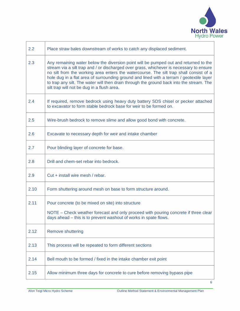
2.2 Place straw bales downstream of works to catch any displaced sediment.
2.3 Any remaining water below the diversion point will be pumped out and returned to the stream via a silt trap and / or discharged over grass, whichever is necessary to ensure no silt from the working area enters the watercourse. The silt trap shall consist of a hole dug in a flat area of surrounding ground and lined with a terram / geotextile layer to trap any silt. The water will then drain through the ground back into the stream. The silt trap will not be dug in a flush area.
2.4 If required, remove bedrock using heavy duty battery SDS chisel or pecker attached to excavator to form stable bedrock base for weir to be formed on.
2.5 Wire-brush bedrock to remove slime and allow good bond with concrete.
2.6 Excavate to necessary depth for weir and intake chamber
2.7 Pour blinding layer of concrete for base.
2.8 Drill and chem-set rebar into bedrock.
2.9 Cut + install wire mesh / rebar.
2.10 Form shuttering around mesh on base to form structure around.
2.11 Pour concrete (to be mixed on site) into structure
NOTE – Check weather forecast and only proceed with pouring concrete if three clear days ahead – this is to prevent washout of works in spate flows.
2.12 Remove shuttering
2.13 This process will be repeated to form different sections
2.14 Bell mouth to be formed / fixed in the intake chamber exit point
2.15 Allow minimum three days for concrete to cure before removing bypass pipe

7
Afon Teigl Micro Hydro Scheme Outline Method Statement & Environmental Management Plan
3 Pipeline
The pipeline is to be made from 12m lengths of Ø 500mm HDPE pipe, fusion welded on site using electro fusion couples.
The pipe will be buried in a shallow trench (maximum 2m deep). The route is shown in the general layout drawing.
A gate valve will be installed at both ends of the pipeline to allow manual shut-off.
3.1 Deliver pipe to site.
3.2 Extreme care taken to avoid contact with archaeologically sensitive areas at all times, as considered within the Design and Access Statement.
3.3 Place sections of pipe along route using tracked dumper.
3.4 Excavate pipe trench in short sections.
3.5 Starting at the powerhouse, sections of pipe to be welded together using the electro fusion couples, then dragged along the pipe route and laid into trench and reinstated over (Note – unless construction uncovers any sharp rock, no pipe bedding materials is required)
3.6 Single cable to be laid along pipe route. Cable to be covered in silt trench or similar.
3.7 Upper section of pipe route to be fenced off following construction work to allow the
sward to re-establish with greater ease.
4 Powerhouse
The powerhouse is designed around a concrete floor slab which restrains both the
pipe and the turbine. The building will be of concrete shuttered construction with stone
facing, and a turf roof. The turbine will discharge into a concrete sump, with a tailrace
made from Ø 600mm twin-wall pipe.
Care will be taken to prevent runoff flushing excavated material into the watercourse
nearby.

8
Afon Teigl Micro Hydro Scheme Outline Method Statement & Environmental Management Plan
4.1 Mark out powerhouse and tailrace.
4.2 Excavate foundation trenches, sump and trench for tailrace.
4.3 Cast wall footings and floor sump.
4.4 Install tailrace pipe.
4.5 Construct formwork for sump around first section tailrace pipe, and formwork for
turbine bed frame. Include anchor block, floor drain and cable ducts (as will be shown
in engineering drawings).
4.6 Cast sump walls and main floor slab, with starter bars for anchor block. Slab to have
slight fall to allow drainage into floor drain, and apron to fall away from building.
4.7 Build up block walls, leaving cut-out for anchor block, and including ventilation
notches top and bottom of southern gable end.
4.8 Fit wall plates, rafters, heavy duty impermeable waterproof membrane and cover with
earth and seeds.
4.9 Fit insulation to internal roof space to control noise, plus baffle boxes over ventilation
notches for same purpose.
4.10 Fit doors and rainwater goods as appropriate.
5 Tailrace & Outfall
5.1 Form barrier around outfall to isolate works for watercourse from steel piles or
sandbags / visqueen
5.2 Dig trench for tailrace pipe to watercourse

9
Afon Teigl Micro Hydro Scheme Outline Method Statement & Environmental Management Plan
5.3 Install tailrace pipe
5.4 Use local boulders to create scour protection and scree at outfall and landscape pipe
exit
5.5 Fit outfall screen (stainless steel with 30mm spacing)
5.6 Backfill pipe (selected backfill to avoid damage)
6 Electro-Mechanical Installation
6.1 Deliver turbine / generator and control panel and ancillaries to site, unload to concrete
apron and use rollers to move into powerhouse lifting area.
6.2 Fit turbine and generator in place, align, bolt down and grout in.
6.3 Fix main inlet valve support to concrete, and check alignment / positioning of unit.
7 Connect & Restrain Pipe
7.1 Pipe to be flushed with intake screen in place to remove debris from pipe (small
stones etc.)
7.2 Cut pipe to length, and fit reducer with stub pipe to suit turbine inlet. Reducer to be
located within anchor block, at upstream end.
7.3 Connect pipe to turbine inlet using VJ coupling or similar, ensuring 5-10mm gap
between flange and end of pipe
7.4 Construct formwork for anchor block, fixing pipe securely to prevent floating in
concrete
7.5 Pour anchor block

10
Afon Teigl Micro Hydro Scheme Outline Method Statement & Environmental Management Plan
7.6 Backfill around block
7.7 Ground to be reinstated as far as reasonably practical to same standard and condition
as prior to construction.
8 Electrical Installation & Power Cabling
8.1 Install control cabinet
8.2 Connect generator, actuator and sensor cables. Install local power and lights.
8.3 Connect signal cable from intake
8.4 New transformer and fuse / metering to be installed on new pole by DNO
8.5 Install LV power cable from pole to powerhouse. Cable to be installed in duct.
Warning tape to be laced in trench, depth and other details to be specified by DNO
8.6 Fuses to be fitted by DNO following electrical installation
8.7 Install intake level sensor(s) under intake screen
9 Final civil’s, making good
9.1 Stone face powerhouse
9.2 Remove straw bales, waste and excess materials, making good.
9.3 Remove sediment from any traps, fill and reinstate turf
9.4 With regarding to removal of bunds, dirty water will be pumped out of working areas
before these are removed.
11
Afon Teigl Micro Hydro Scheme Outline Method Statement & Environmental Management Plan
10 Commissioning
10.1 System commissioning as per turbine supplier instructions
7. Environmental Management Plan
The areas of environmental impact that are relevant to the proposed works include
contamination of the river with concrete and / or silt, fuel or oil spillages and disposal of waste
(both solid and liquid). Specific risks associated with these areas, together with mitigation
procedures to minimise or eliminate these risks are outlined in the following sub-sections.
Relevant EA pollution prevention guidelines will be followed, including:
PPG 01 “General guide to the prevention of pollution”
PPG 05 “Works in, near or liable to affect watercourses”
PPG 06 “Working at construction and demolition sites”
7.1 Specific Flora / Fauna
7.1.1 Otter / Badger
No Hazards will be left overnight and all holes will be covered or fitted with escape routes.
7.1.2 Bats
No lighting will be used on the site at night after 8pm as this could disturb foraging bats.
7.1.3 Breeding Birds
Care will be taken to avoid disturbing breeding birds. As per the environmental report we will
complete a breeding bird survey before work on the scheme begins, if work takes place during
the breeding season.
7.2 Concrete

12
Afon Teigl Micro Hydro Scheme Outline Method Statement & Environmental Management Plan
Any fresh concrete or cement entering the watercourse has the potential to kill fish, and poses
the greatest environmental risk for this project. Great care will be taken at all stages of the work
to prevent concrete or cement entering the watercourse.
7.2.1 Transportation and Storage of Concrete
The volume of concrete required will be of the order of 5-6m3 at the intake and 8-9m3 at the
powerhouse. Concrete will likely be delivered to site pre-mixed for the powerhouse and mixed
on site for the intake. It will then either be tipped into the formwork or shovelled by hand. It must
be ensured that any spillages that occur during transportation cannot enter the river.
Cement will be stored off the ground (e.g. on pallets or boards) and covered from wind and rain.
Concrete will be mixed in a sheltered area to avoid dry cement being blown around, and this will
be done well away from the river, in an area with no risk of runoff entering the watercourse.
7.2.2 Concrete Pouring
Placing concrete at the intake poses the greatest risk of spillage / leakage into the watercourse.
As the majority of the intake work will be in or adjacent to the stream bed, the river will be
diverted well away from the formwork, and the surrounding areas de-watered and protected
from runoff in the event of rain. Plywood sheet will be placed around the areas being poured in
order to collect any spillage.
Concrete casting will only be carried out in dry conditions – a full local forecast will be
obtained daily, and concrete only poured if dry weather is forecast for at least three days.
This will minimise the risk of washout before concrete is cured.
7.2.3 Washing of equipment
A small pit will be dug well away from the river, to contain wash water and allow cement /
concrete to be settled out. All equipment will be washed in / to this pit. Once the cement has
cured the pit can be filled in.
7.3 Silt
Silt, although not as harmful as concrete, can have an adverse effect on the river environment
and all efforts will be made to prevent silt entering the watercourse.
7.3.1 General silt protection
13
Afon Teigl Micro Hydro Scheme Outline Method Statement & Environmental Management Plan
Straw bales will be placed downstream of the intake works to act as stilling ponds to collect
disturbed silt. All working areas will be kept as dry as possible, and runoff from the surrounding
banks should be diverted away from the works.
7.3.2 Excavated material
Where it is deemed to be appropriate, i.e. within close proximity of a watercourse then
excavated material will be placed away from the river on plastic sheeting and will be covered in
the event of rain.
7.4 Fuel & Oil
Fuel or oil entering the watercourse can kill fish, invertebrates and plants and contaminate any
downstream abstractions. It will not be allowed to enter the river.
Fuel storage, and spill kits (including drip trays) will be located within the compound at the
powerhouse location which will be locked when absent from the site. In the event of a fuel
spillage, a clean-up operation will commence immediately using materials on site. Fuel storage
will comply with the Control of Pollution (Oil Storage) Regulations 2001.
7.4.1 Storage
All oil and fuel containers will be placed in suitable containment bunds well away from the river.
The bund volume will be at least 110% of the storage container. Large-scale storage of fuel will
not be required or permitted on site.
7.4.2 Refuelling vehicles or equipment
Any refuelling or oiling is to be carried out well away from the river. Suitable containers and
funnels will be used to avoid spillage, and drip trays or absorbent material will be placed
beneath equipment while filling.
7.4.3 Leakage
Machinery (plant, generators, pumps, etc.) and any fuel storage facilities must be checked daily
to ensure there are no oil leaks.
A clean up kit will be available on site to absorb and contain any spillages.
14
Afon Teigl Micro Hydro Scheme Outline Method Statement & Environmental Management Plan
7.5 Noise
Noise from machinery and equipment will be minimised to reduce the effect on wildlife and the
amenity of neighbours.
7.5.1 Plant machinery noise
There will be 4-6 weeks of excavator work across the site. There will also be noise from general
access and transportation of materials.
7.5.2 Other machinery noise
Generators, pumps and other machinery will be switched off when not in use. Such machinery
will not be required to run continuously, and will not operate outside the hours of 8am to 8pm
except during the period immediately after the intake weir cast in which case pumps will keep
the working areas dry through the night.
7.5.3 Waste Disposal
While we do not envisage us moving or making contact with any type of controlled waste in this
project, we note that this should be removed from the site by a registered waste carrier to an
appropriately licensed site or company.
Copies of all waste disposal licences and waste transfer documents will be filed on site and
available for inspection.
7.6 Waste Water Disposal
The site welfare facilities will generate waste water from toilets and washbasins, and these are
to be fitted with a waste water collection tank that can be pumped clean by a registered operator
for removal and treatment at a local water treatment works.
7.7 Reinstatement
The banks, pipeline route and surrounding areas will be reinstated as appropriate, with
excavations being reseeded if required. As already mentioned and as per the environmental
report, the upper section of the pipe route will be fenced out to allow the sward to re-establish
itself with greater ease.