overhaul manual - igor...
TRANSCRIPT

CONTINENTALL-HEAD
OVERHAUL MANUAL
WISCONSINMOTORS, LLC
2020 Fletcher Creek Drive, Memphis , Tennessee 38133 www.wisconsinmotors .com
(800) 932-2858
2006 All Rights ReservedWisconsin Motors, LLC

WISCONSINMOTORS, LLC
Operation and Maintenance Instructions
CONTINENTALL-HEADENGINES
FOUR CYLINDERN56 -- N62
Y69--Y91--Y112F124-- F135-- F140-- F162-- F163
SIX CYLINDERF186-- F209-- F226-- F227-- F244-- F245
M271 -- M290-- M330-- M363B371 -- B427

QUICK REFERENCE SECTION INDEX First page of eachgroup has black tab insQme position as below.
SECTION I--General Information ...................................................... Page 8
SECTION II -- Lubrication .................................................................... Page 11
SECTION III--Operation .................................................................... Page 17
SECTION IV--Preventive Maintenance ............................................ Page 23
SECTION V--Cooling System .............................................................. Page 28
SECTION VI.--Fuel System .................................................................. Page 35
SECTION VII--Ignition ........................................................................ Page 43
SECTION VIII--Engine Repair & Overhaul .................................... Page 52
SECTION IX--Trouble Shooting ........................................................ Page 73
SECTION X---Torque Specifications .................................................. Page 76
SECTION XI--Li.mits & Clearance Data .......................................... Page 77
(See following pages for details of each section)

I¥ CONTINENTAL L-HEAD ENGINE MANUAL
INDEX
SECTION I E GENERAL INFORMATION
Four Cylinder L-Head Engine Specifications ...................................................... 5Six Cylinder L-Head Engine Specifications .......................................................... 6How to Order Parts ................................................................................................ 7Continental L-Head Engine Features .................................................................. 8
SECTION II -- LUBRICATIONEngine Lubricating System .................................................................................... 11Oil Pump ..................................................................................................................12Air Cleaner ..............................................................................................................13Lubrication Recommendations ................................................................................ 14Transmission and Converter Lubrication Recommendations ............................ 16
SECTION III-- OPERATION
Preparation of New Engine for Operation .......................................................... 17Starting the Engine ................................................................................................ 18Stopping the Engine ................................................................................................ 2010 Operating Precautions ...................................................................................... 21Cold Weather Operation ........................................................................................ 21Seasonal Storage of Engine .................................................................................. 22
SECTION IV E PREVENTIVE MAINTENANCE
Daily Preventive Maintenance Schedule ................................................................ 2350-Hour Preventive Maintenance Schedule ............................................................ 25250-Hour Preventive Maintenance Schedule .......................................................... 26500-Hour Preventive Maintenance Schedule .......................................................... 27
SECTION V m COOLING SYSTEMContinental L-Head Cooling System ...................................................................... 28Effect of Altitude on Cooling .................................................................................. 29Anti-Freezes ......................................... : ............................................: .......................29Cleaning Cooling System ........................................................................................ 30Testing Thermostat .................................................................................................. 31Radiator Pressure Cap ............................................................................................ 32Fan Belt Tension ...................................................................................................... 33Water Pump ............................................................................................................ 33
SECTION VIE FUEL SYSTEM
Gravity Fuel System .............................................................................................. 35Mechanical Fuel Pump ............................................................................................ 35Electrical Fuel Pump .............................................................................................. 36Zenith Carburetor .................................................................................................... 36Marvel-Schebler Carburetor .................................................................................. 37Carburetor Chokes .................................................................................................... 37Governors .......................................................................................................... 39Pierce Governor ........................................................................................................ 41Cam Gear Governor ................................................................................................. 42Tail-Shaft Governors .............................................................................................. 42

CONTINENTAL L-HEAD ENGINE MANUAL
INDEXSECTION VII ~ IGNITION
Battery-- Ignition System ................................................................ 43Ignition Coil- Distributor & Condenser .................................................. 44Distributor Maintenance ............................................................ 45Spark Plugs .................................................................................. 46Distributor--Ignition Timing, with Timing Light .......................... 47Ig~ition Timing, without Timing Light .............................................................. 48Magneto -- Ignition ................................................................................................... 49Magneto Impulse Coupling ........................................................ 50Timing Magneto to Engine ..................................................................... 51Charging Circuit ......................................................................................................................................................51A
SECTION VIII--ENGINE REPAIR AND OVERHAUL
Cyi[inder tIead ........................................................................................... 52Cylinder Block ..................................................................................... 53Valve Seat Inserts .................................................................................... 54VaIves .................................................................................................... 55Valtve Springs ..................................................................................... 56Preparing Cylinder Bores ......................................................................... 57Pistons ............................................................................................ 58Connecting Rods ................................................................................. 59Piston Rings ............................................................................................... 60Bearings ................................................................................................ 61Crankshaft ....................................................................................... 63Camshaft ..................................................................................................... 64Valve Tappets ..................................................................................................... 64Timing Gears ..................................................................................... 65Crankshaft End Play .......................................................................... 66Rear Oil Seals .................................................................................... 67Oil Pumps ............................................................................................ 69Flywheels and Housings .................................................................... 71Reassembling Engine ................................................................................. 72
SECTION IX-- TROUBLE-SHOOTING
Starting Motor Will Not Crank Engine .................................................... 73Engine Will Not Start ................................................................................. 73Engine Runs Unevenly ........................................................................... 74Poor Compression .............................................................................. 74High Oil Pressure .......................................................................... 75Engine Knocks ...................................................................................... 75Engine Vibration ................................................................................... 75
SECTION X ~ TORQUE SPECIFICATIONS ............................................ 76
SECTION XI--LIMITS & CLEARANCE DATA ............................................. 77

FORWARD Good operation and a planned maintenance program as outlined in this manual are of vital importance in obtaining maximum engine performance, and long engine life. The instructions on the following pages have been written with this in mind, to give the operator a better understanding of the various problems which may arise, and the manner in which these problems can best be solved or avoided.
Procedure in the Preventive Maintenance Section must be set up and followed by the owner and operator to obtain dependable service and long life from the engine. Owners and operators are expected to perform these maintenance procedures as outlined under the daily schedule as well as 50-hr., 250-hr., and 5OO-hr. periods WHILE IN THE WARRANTY PERIOD AS WELL AS DURING THE LIFE OF THE ENGINE.
Warranty service does not include tune-up of the engine such as replacing spark plugs, distributor points, tappet settings, ignition timing, ignition wiring, air cleaner service and lubrication and filter maintenance.
The operator is cautioned against the use of any parts, other than Genuine Wisconsin Motors, LLC Continental Parts for replacement or repair. These parts have been engineered and tested for their particular job, and the use of any other parts may result in unsatisfactory performance and short engine life. Likewise, Wisconsin Motors, LLC Continental distributors and dealers, because of their close factory relations, can render the best and most efficient service.
THELIFEOFYOURENGINEDEPENDSONTHECAREITRECEIVES.
CONTINENTALL-HEADENGINEMANUAL Page 1

Page 2 CONTINENTAL L-HEAD ENGINE MANUAL
Y112 Engine
F400 Series
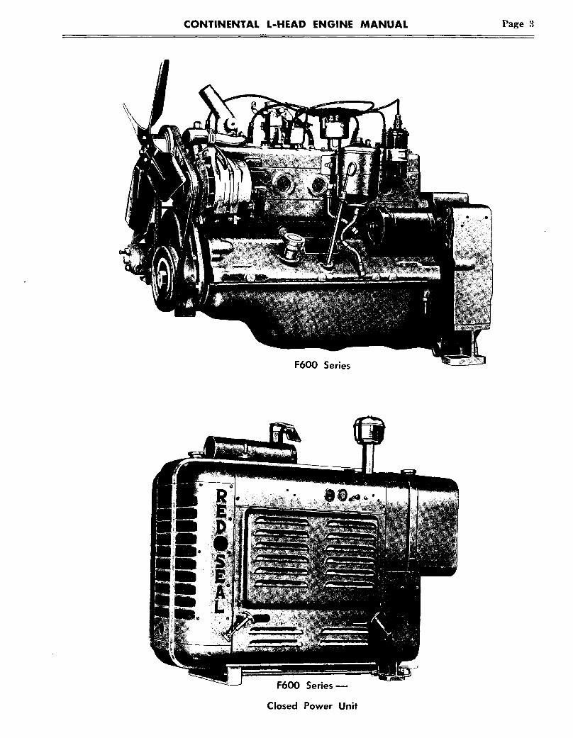
CONTINENTAL L-HEAD ENGINE MANUAL Page 3
F600 Series
F600 Series-
Closed Power Unit

Page 4 CONTINENTAL L-HEAD ENGINE MANUAL
Figure 7 u F600 Power Unit (left side)
Figure 8 ~ F600 Power Unit (right side)

FOUR CYLINDER INDUSTRIAL L-HEAD ENGINES*
MODEL
No. of cylinders
Bore and Stroke
Displacement Cu.
Compression Ratio
Max. Oil Pressure**
Min. Oil Pressure (Idling)
Firing Order
Main Brg. Frt.
Main Brg. Center
Main Brg. Rear
Conn. Rod Brg.
Dia. and Length
N-56
4
2¼ x 3½
6.12
20-30
7
1-3-4-2
2x1~2
N-62
4
2~ x 3~
62
6.46
20-30
7
1-3-4-2
2x1~2
Y-69
4
2~ x 3½
6.66
30-40
7
1-3-4-2
, I~ x 1~e
Y-91
4
2~ x 3½91
6.46
30-40
7
1-3-4-2
Oil CapacityCrankcase
Filter
Total
Valve Clearance
Intake
Exhaust
.015
.01 S
.012
.012
3~½4
.012
.012
3~½4
.012 I
.020
Water Capacity
Engine
Engine and Radiator
Weight (Bare Engine)
(Given approximately 1 quart for hoses)
2 3~ 3~
11 14 15
180 290 290
in quarts-- add
2
11 I
210 j
Y-112 F-124
3~ x 3~112
6.07
30-40
7
1-3-4-2
1~44 X 17/116
3½
4
.012
.020
3~15
290
4
3x4~
124
6.28
20-30
7
1-3-4-2
2¼x1~2¼ x I~2¼ x1~
.014
.016 ©
5
14
415
*Dimensions and data shown are for Standard Industrial Engines.
**Note: Other all pressures are available, based on customer specifications.
***OH pressure with oil pressure relief valve spring number 10EL00230 on engines built after December 1971. Previousto that, all pressure relief valve spring F400LO0223 was used with 20-30~ pressure.
~ StaHc or cold setting .017
F-13S
4
3~ x 4~
135
7.2:1
30-40***
7
1-3-4-2
2~ x 12~
2~ xl~
F-140
4
3~ x 4~140
6.00
20-30
7
1-3-4-2
2¼x1½~¼xl~2¼x1~
F-162
4
3~6 x 4~
162
6.01
20-30
7
1-3-4-2
2¼x1¼2¼ x1~2¼xI~
4
½4~
.012
.020
5
14
415
4
½4½
.014
.016 ~
5
14
415
.014
.016 o
F-163
4
3~ x 4~
162
7.4:1
30-40***
7
1-3-4-2
2~ xl~2~ x
2~ x1~
4
½4~
.012
.020
5
15
415

SIX CYLINDER L-HEAD ENGINES*
M 0 D E L F-186 F-209 F-226 F-227 F-244 F-245 M-271 M.290 M-330 M-363 B-371 B-427
Ha. of Cylinders
Born & Strokn
0isplacnment Cu. In.
Compression Ratio
Max. 0il Pressure**
Min. 0H Prnssurn
Firing 0rdnr
Main Rrg.--Front
Main grg. -- Int.
Main Brg.--Center
Main Br9. --Rear
Conn. Rod Rrg.
Oia. & Length
0il CQpocityCrankcase
Filter
Total
Valve Clearance
Intake
Exhaust
Water Capacity
Engine
Radiator
Total
Weight--Rare Engine
6
3x4~
6.43
20-30
7
I-5-3-6-2-4
21/4 x 11./~
(2) 2¼ 1~6
5
.014
.016~
6½10~22
17’
~0
6
3~ x 4~209
6.09
20-30
7
6
226
6.02
20-30
7
6
3~ x 4~
22~
7.28
’~0-40"**
7
6
244
~.9
20-30
7
6
3~e x 43/e
244
7.2
30-40***
7
6
3~/~ x 43/~e
271
6.12
30-40
7
6
33.3.~ x
290
S.96
30-40
7
6
4x43/e
330
6.75
30-40
7
4 x 41~e
363
6.70
30-40
7
1-5-3-6-2-4
2¼ xl~(2) 2~ xl~6
2¼ xl~/~
5
s½
.014
1-5-3-6-2-4
(2) 2~ xI~6
5
½s½
.014
.016~)
1,5-3-6-2.4
(2)2~ xl~
2~ ~ I~
S
.012
.020
1-5-3-6-2-4
(2) 2~ xl~
2~ X13~4
5
½s½
,014
.016~
(Given in quarts ~ add approximately qt. for hose,s)
~0½ lo½ 1o½ 10½17 17 17 17
550 SSS 555 565
1-S-3-6-2-4
(2) 2~ xl~e
2~x~¼
1-5-3-6-2-4
2~ x1~4
(4) 2~ xl~
2%
2~ x~
1-5-3-6-2-4
2~ x12~
(4) 2% x1~6
2~ x2¼2% xlt~
2¼ x~
1-5-3-6-2-4
2% x1~4
(4) 2~ xl~
2% x2~
2¼ x~
1-5-3-6-2-4
2~ xl~(4) 2% xl~e
2~ ~2¼
5
½s½
.012 .017
.020 .020
13½
IT 31
565 800
.017
.020
13½
31
800
.017
.020
13½
33
800
,017
.020
13½
33
800
*Dimensions and data shown are for StanCard Industrial Engines.
~’*Note: Other all pressures are available, based on customer specifications.
~**Oil pressure with all pressur~ relief valve sp~ing number TOELC)O230 on engfnes bu?ft after December 1971. Previou~to that, oil pressure relief valve spring F4OOLO0223 was used with 20-30-’~: pressure.
6
4~/~ x4S/~
371
5.96
40-50
7
1-S-3-6-2-4
2~ x(4) 2~
2~ x~62~ x2½
.017
.022
16
2G
36
945
6
4~¢~ ~ 4½427
5.76
40-50
7
1-5-3-6-2-4
2~ x 1~
21~2 x1½
.017
.022
16
20
36
950
ZC::

CONTINENTAL L-HEAD ENGINE MANUAL Page 7
INFORMATION FOR ORDERING PARTS
When ordering’ parts, refer to the engine name plate attached to side of the cylinder block, which liststhe model and serial number. In most cases a specification number is listed. This data is of vital impor-tance in obtaining the correct parts : always include this information on your parts order.
Figure 9 w Nameplate

Page 8 CONTINENTAL L-HEAD ENGINE MANUAL
SECTION 1GENERAL INFORMATION
L-Head engines have inherent design advan-tages which result in a more simple engine of lowerheight, weight and cost. All valves, cams, valvelifters and all other moving parts are a part of thecylinder block assembly.
The cross-section of an L-Head engine resem-bles the letter "L" written upside down and en-gines with this type of combustion chamber arealso called side-valve engines.
Intake and exhaust valves are located in the sidepocket and both are directly operated through tap-pets from a single camshaft. This provides a sire-ple and heavy duty valve gear, since there is nodeflection. Figure 10 ~ L-head design
CONTINENTAL L-HEAD ENGINES
Continental has eight basic four-cylinder andten six-cylinder L-Head type engines, ranging insize from 56 to 427 cubic inch displacement.
The combustion chamber design has been tai-lored for the required turbulence, charge flow andburning characteristics to provide dependable andeconomical heavy duty service.
Some of the principal design features are:
1. Individual Porting -- of the intake manifoldwhereby each cylinder is fed with the fuel-airmixture individually and not influenced by othercylinders of the engine.
This is accomplished by casting the cylinderblock with individual intake valve passages foreach cylinder and connecting these passages to anintake manifold which also has individualized pas-sages for each cylinder.
This equal distribution results in maximumpower, smooth operation, easy starting and longerengine life.
Figure 1 1 ~ Individual Parting

CONTINENTAL L-HEAD ENGINE MANUAL Page 9
2. Directional Cooling -- is accomplished by regu-lating the course of the cool water from the waterpump so it first comes in contact with exhaust valveseats and then to other points as indicated by theirrelative temperatures.
This feature promotes unif~m cooling through-out the system, prevents hot-spots and prolongsvalve life.
This coupled with the by-pass and thermostatincluded in tl~e engine assembly, insures rapidwarm-up and even temperature distribution.
3. Full Length Water Jackets- completely sur-round all cylinder bores the full length of the pistontravel.
This insures uniform cooling with minimum boredistortion- which results in lower oil consump-tion ; less blow-by and minimum tendency to sludge.
Figure 12 ~ Directional Cooling in Block
4. Removable Tappets-- The large, barrel shaped,pressure lubricated tappets are so designed that byremoving the adjusting screw--the main bodycan be lifted out and replaced from above throughthe valve chamber. This eliminates the costly serv-ice operation of dropping the oil pan and pullingthe camshaft. Locking of the adjustment is bothsimple and effective.
Figure 13 ~ Full Length Water Jackets
5. Choice of Fuels -- Gasoline - LPG - Natural Gas- Fuel Oil -- Cont:inental L-Head engines have beentailored for heavy-duty operation using gasoline -LPG - natural ga~s - fuel oil fuels.
Figure 14 ~ Removable Tappets

Page 10 CONTINENTAL L-HEAD ENGINE MANUAL
More than conventional number o[ studs toprevent gasket failures, distortion ol:bores and valve seats
Cylinder head
Chr,
I:ull length water
Piston ~
Heavily ribbed alloy cast iron
Full pressure lubrication to all main, connect-;ng rod and cam bearings, as weJl as tappetsand timing gears
Spurt hole ~or I~brication of thrustotcylinder walls, piston pins, and coolingol: piston head
Drop forged, counterwe~ghted crankshaft;
Alloy steel heat treated connecting rodand main beating bolts and nuts
Dipstick-
~loet-o Screen
piston pins
inserts
Exhaust valves
guides
/abe springs
Positive Roto exhaust valves
removable without pullingcamsha~:
"Main and connecting rod bearings
Crankcase ventilation
Submerged gear b/pe oil pumpdriven off camshaft
Figure 15 ~Cross Section of aTypical Continental "L" Head Engine

CONTINENTAL L-HEAD ENGINE MANUAL Page 11
SECTION IILUBRICATION
ENGINE LUBRICATION SYSTEM
Continental L-Head engines have full pressurelubrication to all main, connecting rod and cam-shaft bearings as well as tappets and timing gears.
To insure piston pin lubrication and prevent pis-ton scuffing during the warm-up period in cold
weather--the large end of the connecting rodshave drilled spurt holes pointing toward the thrustside of the pistons. These line up with the oil holein the crank pin so that once each revolution, oil issprayed on the cylinder wall for lubrication.*
CRANKSHAFT
Figure 16 ~ Oiling Diagram
NOTE: On some recent models, the connecting rod spurt holes have been plugged or eliminated.This does not in any way effect the lubrication of the engine.

Page 12 CONTINENTAL L-HEAD ENGINE MANUAL
Figure 17--Connecting Rod Spurt Hole(see note on page 11)
OIL PUMPOn all engines except the N-series, a large ca-
pacity, submerged, gear type oil pump is drivenoff the camshaft and protected by a large screeninlet; on the N-series the oil pump is mounted onthe rear end plate.
An adjustable by-pass valve maintains suitableoil pressure from idle to maximum speed automat-ically.
Refer to pages 5 and 6 for complete oil pressurefigures.
A by-pass type oil filter is normally provided toremove dirt and foreign elements from the oil, apercentage of which.is passed through the filterdm’ing the operating period. The removal of grit,sludge and foreign particles causes filter elementsto clog and become ineffective unless they arenormally replaced every 150 hours.
OIL CHANGE FREQUENCYEngine oil does not "wear out". However, the
lubricating oil in internal-combustion engines be-comes contaminated from the by-products of com-bustion: dirt, water, unburned fuel entering thecrankcase, and the detergents holding the carbonparticles in suspension in the crankcase.
CAUTION: If the oil pressure is erratic orfalls below these limits, stop the engine IM-MEDIATELY ~.~d find the cause of the trouble.Refer to trouble shooting section for this in-formation.
Figure 19 ~ Oil Filter
The schedule for changing oil is directly de-pendent upon the operational environment: anextremely clean operation could go 150 hours whilea dirty operation (foundry or cement factory)could be 50 hours or less.
RUNNING-IN NEW ORRECONDITIONED ENGINES
No ~pecial oil is required -- use the oil recom-mended for the ambient temperature. (See charton page 14.)
Figure 18~0il Pump
*Other pressures are available, based on customerspecifications.

CONTINENTAL L-HEAD ENGINE MANUAL Page 13
DO NOT FLUSH CRANKCASE WITH KEROSENE
Some operal:ors un~visely put kerosene in thecrankcase after draining the engine oil, then turnthe engine over with the starter--in the beliefthey are doing a better job of crankcase cleaning.
In doing this, kerosene is circulated through theoil pump, the main oil header and the branchesleading into the engine bearings -- thereby wash-ing away the protective oil film. In addition, someof the kerosene will be trapped and remain to thinout the new oil, reducing its lubricating qualities.
Do not put kerosene into the crankcase. The bestmethod is to drain the oil when the engine is thor-oughly heated .-- which will carry off most of thesediment.
AIR CLEANERAll engines, when operating, consume several
thousand cubic feet of air per hour. Since dustyair is full of abrasive matter, the engine will soonwear excessively if the air cleaner does not removethe dust before entering the cylinders.
Two basic types of air cleaners are normallyused -- the oil bath type and the dry replaceableelement type.
INLET
Figure 20--Sectional View of Oil Bath Air Cleaner
O~?era~ing condRions determine the air cleanerserwce periods. ~n e×treme]~ dusty operations,this may be once or twice daily. In dust protected
areas, the air cleaner should be serviced whenchanging oil.
As the dirt is strained from the air flowingthrough the cleaner, it thickens the oil in the cupand raises the level. If the level is too high, agita-tion of the oil on the screen is affected and grittyoil is carried over into the air stream, through thecarburetor and into the engine cylinders. Thiswould actually introduce a grinding compound withresulting very rapid wear.
Figure 21- Dry Replaceable Element TypeAir Cleaner
By actu~! measurement, the amount of dustshown below, when admitted in the volume shownevery hour, will completely ruin an engine in aneight hour day.
Figure 22Proper servicing means Cleaning Thoroughly
and Refilling with New Engine Oil, and Maintain-ing Air-Tight Connections between the air cleanerand intake manifold so that All Air Entering TheEngine Is Filtered.

Page 14 CONTINENTAL L-HEAD ENGINE MANUAL
LUBRICATION RECOMMENDATIONS
Motor oils used for internal-combustion enginelubrication perform many useful functions including:Dissipating heat, sealing piston rings, preventingmetal-to-metal contact wear and reducing power lossthrough friction.
The lubricating oil recommendation is based uponengine design, type of service, and the atmospherictemperature prevailing. High quality oils are re-quired to assure maximum performance, long enginelife, and minimum cost of operation.
L-Head gasoline engines operate in a wide rangeof service conditions and seasonal temperatures, soour recommendations are given for various types Ofservice and ambient temperatures.
NEW API SERVICE DESIGNATIONS
API has adopted a new Engine Oil Performanceand Engine Service Classification System. We re-commend using the two oils described below for allL-Head engine applications (Gasoline - LPG - NaturalGas).
The new API designations are explained as follows:
SD - SERVICE CLASS D
Service typical of industrial gasoline enginesoperating under engine manufacturers’ warranties.Oils designed for this service provide more pro-tection from high and low temperature enginedeposits, wear, rust and corrosion in gasolineengines than oils which are satisfactory for APIService Classification SC* is recommended.
SE - SERVICE CLASS E
Service typical of industrial gasoline enginesoperating under engine manufacturers’ warranties.Oils designed for this service provide more pro-tection against oil oxidation, high temperatureengine deposits, rust and corrosion in gasolineengines than oils which are satisfactory for APIEngine Service Classifications SD or SC* and maybe used when either of these classifications is re-commended.
Former New
MS SD
Oil Type
High Detergent - Exceedsengine manufacturerwarranty requirements.
MS SE High Detergent - Exceedsengine manufacturerwarranty requirements.
S.A.E. OIL BODY GRADES
The oil body grades available from the lightest(SAE 5W) to the heaviest (SAE 40)
30 I 40
Multi-Grade Oils such as SAE 5W-20 and SAE 10W-30 have the starting grade characteristics of thelighter oil and after it warms up it has the runningcharacteristic of the heavier grade.
The following SAE grades are general recommen-dations for Continental L-Head engines during changingseasonal atmospheric temperatures:
SEVEREENGINE WINTERSERIES BELOW O°F.
N SAE 5W-20
Y SAE 5W-20
F SAE 5W-20
M sAE 5W-20
B SAE 5W-20
NORMALWINTER
0o . 32~F.
lOW
lOW
10W
20W
20W
SPRING.FALL32° . 75OF.
SAE 20W
SAE 20W
SAE 20W
SAE 30
SAE 30
SUMMERABOVE 75°F. i
SAE 30
SAE 30
SAE 3O
SAE 40
SAE 40
The Multi-Grade oil used should cover the singlegrade recommendation for the atmospheric tempera-ture involved, e.g. SAE 10W-30 covers SAE-10W,SAE-20W, SAE 20 and SAE 30.
Generators, Starters, Distributors-Add 3-5 dropsof engine oil to the generator and starter oil cupsevery 50 hours and to the distributor every 250 hours.
AIR COMPRESSORS (ENGINE MOUNTED) normallyare engine lubricated. However, if lubricated sepa-rately from the engine, use the same type and gradeas used in the engine.
* SC mild detergent oil, formerly MM.

CONTINENTAL L-HEAD ENGINE MANUAL Page 15
Clutches -- Use a high temperature bearinggrease. Do not. over-lubricate.
Conventional Transmissions -- For the greatestefficiency over the life of the transmission, use ahigh quality straight mineral oil. The oil shouldbe changed sea:sonally.
Use the following proper grades :
ClarkFullerTwin DiscWarner
SUMMER
SAE 90SAE 140SAE 4OSAE .140
WINTER
SAE 90SAE 90SAE 40SAE 90
Torque Converters and Hydraulic or AutomaticTransmissions---These units employ a fluid me-dium to transmit power which must be very stable
to resist formation of harmful deposits or changein body in use. The correct fluid must be selectedto obtain maximum efficiency of the transmission.All fluids should be changed seasonally.
Type "A" Automatic Transmission fluid is mostwidely used. There are many widely distributedbrands of this type.
For some models of Twin Disc Clutch Company’storque converters, a Special Fluid having a viscos-ity of 35 Saybolt seconds @ 100° F. is, required --other models use SAE 10W engine oil. The Speciallow viscosity fluid may be obtained from Twin DiscClutch Company Dealers. To satisfy the SAE 10Wrequirement, we recommend the use of MS typeoils.
Allison Division torque converters and Torqma-tic transmissions require a type C fluid.
Figure 22AF600 Engine with a Hydraulic Coupling

Page 16 CONTINENTAL L-HEAD ENGINE MANUAL
TRANSMISSION AND CONVERTER LUBRICATION RECOMMENDATIONS
The following grades are generally recommended for hydraulic torque converters and transmissionsfor Summer and Winter operation:
MANUFACTURER
Continental Motors Corp.Co-Matic DriveFluid Coupling HC15
Clark Equipment Co.Torcon (converter only)Torcon Converter and Transmission
Fuller Mfg. Co.Torque Converter
Borg-WarnerBorg & Beck & Long Mfg. Co.
All converters and hydraulictransmissions
Allison DivisionTorque Converters andTorqmatic Transmissions
SUMMER
Type AType A
SAE 10WType A
SAE 10W
Type A
WINTER
Type AType A
Fluid MediumexceptTwo speed transmissionand converter transmission combinations(Models T-DRR-FT-IT) Type A Type A
Reverse TransmissionsModels RR-CRR-ICRR SAE 40 SAE 20
NOTE: For all Grease applications on the above units a good high temperature grease should be used.
Type C Type C
Twin Disc Clutch Co.Hydraulic Reverse GearsCoupling or Power Take-off SAE 10W SAE 10W
Hydraulic Converter TransmissionsInput shaft & impeller bearings (C, FC) Same as Engine
Special Twin-Disc Fluid
Type A
Type A (below ° F.)
Type A (below 10° F.)Type A

CONTINENTAL L-HEAD ENGINE MANUAL Page 17
SECTION IIIOPERATING INSTRUCTIONS
The person operating the engine naturally as-sumes responsibility for its care while it is beingoperated. This is a very important responsibilitysince the care and attention given the engine goesa long way in determining how long a period it willoperate satisfactorily before having to be shutdown for repairs.
The operating and preventive maintenance in-structions for the L-Head type engines are simpleand should be followed without deviation.
The entire aim in setting forth these instruc-tions is to give you the benefit of the knowledgeand experience gained over a long period of col-laboration between Engineering Research andField Service.
PREPARATION OF NEW ENGINEFOR OPERATION
Before placin~ a new engine in operation, it mustbe thoroughly inspected for external damage andparticular attention paid to the following items:
1. Inspect Engine Hold Down Bolts -- To makecertain that they are firmly set.
2. Manifold Heat Valve Setting -- The "F"series of industrial engines have an adjustablesector on the exhaust manifold which can pro-vide added hex~ on the intake manifold for lightoperations with excessive idling.
~" POSITION
Normal Operation
1/2 "01~1" POSITION
Low Speed- Light Load Operation
Figure 23- Heat Valve Setting
NORMAL OPERATIONSet the sector on "OFF" position for warm
weather operation, as there is enough heat onthe intake manifold to properly vaporize the fuel.
CAUTION: Adding more heat willreduce the power.
LOW SPEED - LIGHT LOAD OPERATIONS
S6t the sector at 1/~ to 1/2 "ON" position - orminimum position for good idling.
This setting provides added heat from theexhaust manifold to circulate around a sectionof the intake manifold and assist vaporization.
This setting results in some power loss - butwill provide good idling and low speed operationwith normal fuel - air ratio.
COLD WEATHER OPERATIONSet the sector to "FULL ON" position.
CAUTION: Tighten sector nut in correct position- so it will not loosen in operation.
3. Open Fuel Tank Shut Off Valve--By turn-ing handle counter-clockwise us far as it will go.
Figure 24- Fuel Shut-off Valve
4. Close water drain cock -- in lower radiatorconnection, also on the side of the block. (In somecases, this may be a pipe plug.)
Figure 25 ~ Water Drain Cock

Page 18 CONTINENTAL L-HEAD ENGINE MANUAL
5. Fill Crankcase with oil shown in chart onpage 14.
8. Engine Accessories -- see that all points re-quiring lubrication are Drol~erly supplied.
Figure 27
6. Fill Radiator with Clean Water -- duringfreezing weather, use a sufficient amount of anti-freeze to protect the system for the lowest antic-ipated temperature -- refer to Section V.
Figure 28
7. FILL GASOLINE TANK FULL m All newengines are shipped with a treated tank whichshould be completely diluted with a full tank ofgasoline to eliminate any tendency to dog.
Be sure that the container used for filling isclean and free from dirt. Replace cap securely.
Figure 30
9. Electrical Connections -- check storage bat-tery terminals and all electrical connections. Checkeach spark plug wire for tightness.
Figure 31
10. RADIATOR COOLANT CAPSULE -- Theradiator coolant capsule, which comes with theengine, is a water conditi.oner and anti rust inhib-itor to protect the cooling system. Remove cello-phane wrapper before using.
STARTING THE ENGINENormally check daily preventive maintenance
schedule before starting. -- (See Section IV).
1. Safety Control Switch -- (If supplied)Turn Manual control knob with arrow pointingtoward "on" position. When oil pressure builds upto normal, control knob will automatically releaseand arrow will point to "run" position.
Figure 29 Figure 32 m Safety Switch

CONTINENTAL L-HEAD ENGINE MANUAL Page 19
2. Disengage Power Take-Off -- (if equipped)Starting engine under load throws overload onstarter and battery.
Figure 33 ~ Power Take-off
3. Open throttle Control about 1/3 open
4. Turn on Ignition Switch
5. Pull Out Choke (if manually operated)But avoid flooding the engine. Operate the enginewithout choking as soon after starting as possible.
6. Push Starter Button InKeep on until engine starts ; but not longer than 15seconds at a time.
8. Check Oil Pressure
MODEL OIL PRESSURE
N Series
F Series(with F400L00223 oilpressure relief spring)
F Series(with 10EL00230 oilpressure relief spring)
Y-M Series
B Series
30-40¢~
3o-40#40-50#
~Refer to pages 5 & 6 for additional oil pressureinformation.
Figure 35- Oil Pressure Chart(Other pressures available for special Applications)
9. Check Water Temperature
Figure 36 w Water Temperature Gauge
10. Check ignition timing
CAUTION:After starting new engine- run it at izllefor 5 minutes, then stop engine and recheckoil level in crankcase- then bring oil levelto high mark on dipstick.
Figure 34--Instrument Panel
7. Warm-up Before Applying LoadIdle the engine about 700 R.P.M. for a few minutesto circulate and warm oil -- then increase the speedto approximately half throttle until the enginewater reaches 10/) ° F. This procedure will prolongthe engine life.
IMPORTANT!Breaking in a new or rebuilt engine--forpeak performance and economical operation,~ne ]o~towmg adjustments should be made atend of first 50 hrs. operatzon.
1) Torque down cylinder head studs tospecifications.
2) Adjust valve tappets to specifiedclearances.
3) Adjust idle mixture and idle speedto 400-600 R.P.M.

Page 20 CONTINENTAL L-HEAD ENGINE MANUAL
SPEED CONTROLThe throttle control is used to close the carbure-
tor butterfly valve to limit engine speed belowgoverned speed.
Engines are provided with a mechanical orvelocity governor set to maintain the load andspeed specified when the engine is ordered. If in-dividual requirements necessitate a change ofgoverned speed -- reset governor as outlined under
"Governor adjustment", but do not exceed manu-facturers recommended maximum speed, since thishas been worked out with the end product require-ments in mind.
When extended periods occur between the ap-plications of load, it is recommended that the en-gine be throttled down to minimum idling speed or,if the intervals are unusually long, that it be shutdown.
Figure 37 ~ Throttle Lever(This may vary with the application.)
STOPPING1. Disengage Power Take-Off
2. Reduce engine Speed to Idle -- If hot, runengine at idle (400-600) for several minutes to cool.
THE ENGINE3. Turn Off Ignition Switch -- if engine con-
tinues to run due to high combustion chambertemperatures, either continue idling to furthercool or shut off fuel supply.
CAUTION:NEVER PULL OUT CHOKE WHEN STOP-PING ENGINE -- BECAUSE RAW GAS-OLINE WILL WASH LUBRICANT FROMCYLINDER WALLS.
Figure 37A ~ Hand Throttle Control

CONTINENTAL L-HEAD ENGINE MANUAL Page 21
10 OPERATING1. Oil Pressure -- should be up to recom-
mended pressure at operating speed and over7 pounds at idle (400-600 R.P.M.)
2. Ammeter -- should register "Charging"at all times engine is running. (A voltage reg-ulator, if used, may limit it to a very lowreading).
3. Water temperature -- Normal operation178 to 205° F. A pressure cap determineshigher temperatures. Overheating is detect-ed by loss of coolant. "Frequent Readings ofGauge should become a Habit."
4. Muffler Restriction -- should not exceed20" water or 1!/.2" Mercury. Inspect mufflersperiodically for restrictions to prevent burnedvalves.
5. Clean and Service Air Cleaner -- as rec-ommended to maintain its efficiency. Therapidity that dirt collects in the oil cup in-dicates how often the air cleaner should beserviced.
6. When engine is Over-Heated -- do notadd water -- allow engine to cool so as to pre-vent cracking the cylinder head.
PRECAUTIONS7. Engine Load Indication -- a manifold
vacuum of 6 inches of Mercury indicatesthe recommended maximum continuous fullload operation and a vacuum of 18-20 inches ofMercury indicates normal idling vacuum. Be-tween full load and idling, vacuum gauge read-ings may be used to approximate the per-cent. Any reading below 6" HG indicatesengine is overloaded for continuous duty.
8. Avoid Cold-Sludge Condensation- byprotecting unit to maintain crank case tem-perature over 135 ° F.
9. Idling engine -- slow engine down tolow idle (600 RPM) for about 5 minutes aftereach operating period before stopping. Toorapid cooling down may cause distortion. Donot run at low idle for prolonged periods.
10. Follow Preventive Maintenance Sched-ules Recommended -- This will avoid troubleswhich might cause expensive breakdowns andmaintain your engine for dependable andeconomical operation.
COLD WEATHER OPERATIONThe oil used during cold weather should have a
cold test below the lowest anticipated temperaturesthat will be encountered during its use. The newmultigrade lubricating oils 5W-20 and 10W-30 areideal for cold starting with its reduced initial draguntil warmed up, when it assumes the character-istics of the heavier oil.
Sludge forma{ion at low temperatures is a closesecond to dirt in causing engine damage and wear.This is formed by the piston combustion gasesmixing with the fine oil mist in the crankcase andcondensing on a cold surface. This condensationforms both a sui!phuric and sulphurous acid whichcombines with the oil to become a highly injurioussludge. This dew point is about 135° F. -- whencrankcase temperatures are higher, the contam-inated gases remain in gaseous form and the engineoperates clean as long as breather system is keptclean -- howeve:t" temperatures below this will re-sult in injurious sludge formation. It is vitally im-portant therefore to maintain oil and crankcasetemperatures above 135° F., as shown on the fol-lowing chart :
REACTION WITHIN ENGINE CRANKCASE TO
TEMPERATURES DURING OPERATION
CLEAN ENGINEOPERAT I O N
SLUDG I N G..,:ETCHING OF PARTSRI NG AND VALVESTICKING ANDBURNING OF5ATION BEARINGS.
SLUDGE ANDFREEZING OFOIL
S NOW SCREENS ANDPUMPS RESULTI NG
AN D ~N BURNED BEAR-INGS AND STRIP-
I C E PED PUMP GEARS.
Figure 38

Page 22 CONTINENTAL L-HEAD ENGINE MANUAL
When sludging conditions prevail, the oil shouldbe examined daily and changed as it may freeze,or clog the inlet strainer and cause bearing failures.
High Altitude Operation -- High Altitude opera-
tion reduces the power output approximately 31/~2 %for every 1000 feet of altitude above sea level.
High Temperature Operation for every 10 ° above60° F. carburetor air temperature -- a power lossof 1% results.
PREPARATION OF ENGINE FORSEASONAL STORAGE
CAUTIONBefore starting the processing, engine must be cooled down to the surround-ing temperature, since oil will adhere much better to cold metal surfaces.
1. Drain Oil from Oil Pan--and replacedrain plug.
2. Refill Oil Pan -- with high gradeSAE 30 or 40 engine oil to 1/.2 its normalcapacity.
3. Start up Engine--and run at above600 R.P.M. for 2 minutes to complete oildistribution on all surfaces -- Do Not RunLonger Than 2 Minutes.
4. Stop Engine--Rembve all Spark Plugs.
5. Pour 3 Ounces of SAE 30 or 40 En-gine Oil -- into each Spark Plug Hole.
6. With Ignition Cut Off-- Crank enginewith Starter -- for at least a dozen revolu-tions to distribute this oil over the cylinderwalls and valve mechanism.
7. Drain Oil from Pan and ReassemblePlug.
8. Drain Cooling System and Close DrainCocks.
9. Drain All Gasoline--from tank, linesand carburetor bowl.
10. Replace All Spark Plugs.
11. Seal Air Cleaner Inlet m exhaust out-let- Crankcase Breather Tube-- withweather proof masking tape.
12. Check Oil Filler Cap--Gas Tank Capand Radiator Cap to make certain they aresecurely in place.
Note: If Mil-L21260 No. 30 oil is available, substitute in Steps 2 and 5 above.
SHORT TERM
(Instructions below should be adhered toevery 90 days on outside storage and every6 months on inside storage.)
If the shut down period is to be over 30 daysduration, the following instructions should beadhered to :1. Stop engine, remove spark pIugs.
2. Pour 3 ounces clean engine oil in eachspark plug hole.
3. With ignition cut off, crank engine withstarter at least a dozen revolutions to dis-
STORAGEtribute this oil over the cylinder walls andvalve mechanism.4. Replace all spark plugs.5. Remove drain plug from carburetor bowl,and drain gasoline.6. Replace drain plugs.
CAUTION: Gasoline evaporates if left incarburetor for long periods. This evaporationof gasoline will leave a gum and varnish coat-ing over jets and moving parts ; when engineis started up again, you may have floodingor poor operation from carburetor.

CONTINENTAL L-HEAD ENGINE MANUAL Page 23
SECTION IVPREVENTIVE MAINTENANCE
In order to obtain maximum efficiency from yourgasoline engine, a definite maintenance programshould be set-up and followed. Haphazard main-tenance will only lead to faulty engine performanceand shorten engine life.
All moving parts in the engine are subject towear; however, wear can be retarded by carefuloperation and a planned maintenance program.
In general, gasoline engine operation demandscareful attention to the cleanliness of air, fuel andoil and maintaining operating temperatures of180°-200° F.
The following pages, covering DAILY, 50-250and 500 hour maintenance, have been worked outwith our field service division as "Minimum Re-quirements" to keep your engine in dependableoperating condition.
DALLY
PREVENTIVE MAINTENANCE SCHEDULE
1. OVERALL VISUAL INSPECTION OF ENGINE
Look for evidence of fluid leaks on floor, cylin-der head and block, indicating loose fuel, oil orwater connections -- tighten if found.
Figure 39--Check for Possible Leakage
2. CHECK OIL LEVEL OF ENGINEThe dipstick indicates the high and low oil level
in the crankcase~make allowance for additional~ildrainage back into oil pan if engine has not beenstopped 15 minutes. The most efficient oil level isbetween the two dipstick levels.
Figure 40 ~Check Oil Level of Engine
Do not add oil until oil level approaches thelow mark- then add only enough to bringit to high level ~ NEVER above.
Do not operate the engine with oil below lowlevel mark.
P~ge 24 CONTINENTAL L-HEAD ENGINE MANUAL
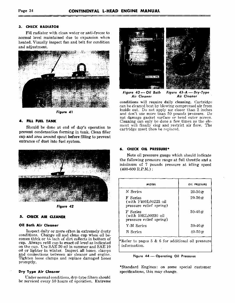
3. CHECK RADIATOR
Fill radiator with clean water or anti-freeze tonormal level maintained due to expansion whenheated. Visually inspect fan and belt for conditionand adjustment.
Figure 41
4. FILL FUEL TANK
Should be done at end of day’s operation toprevent condensation forming in tank. Clean fillercap and area around spout before filling to prevententrance of dust into fuel system.
Figure 42
5. CHECK AIR CLEANER
011 Bath Air Cleaner
Inspect daily or more often in extremely dustyconditions. Change oil and clean cup when oil be-comes thick or 1/, inch of dirt collects in bottom ofcup. Always refill cu~) to exact oil level as indicatedon the cup. Use SAE 20 oil in summer and SAE 10oil or lighter in winter. Inspect all hoses, clampsand connections between air cleaner and engine.Tighten loose clamps and replace damaged hosespromptly.
Dry Type Air Cleaner
Under normal conditions, dry-type filters shouldbe serviced every 50 hours of operation. Extreme
Figure 43--Oil Bath Figure 43-A u Dry-TypeAir Cleaner Air Cleaner
conditions will require daily cleaning. Cartridgecan be cleaned best by blowing compressed air frominside out. Do not apply air closer than 2 inchesand don’t use more than 50 pounds pressure. Donot damage gasket surface or bend outer screen.Cleaning can only be done a few times as the ele-ment will finally clog and restrict air f~ow. Thecartridge must then be repl~tced.
6. CHECK OIL PRESSURE*
Note oil pressure gauge which should indicatethe following pressure range at full throttle and aminimum of 7 pounds pressure at idling speed(400-600 R.P.M.)
MODEL OIL PRESSURE
N Series
F Series(with F400L00223 oilpressure relief spring)
F Series(wi~h 10EL00230 oilpressure relief spring)
Y-M Series
B Series
30-40¢~
30-4022
40-50¢~
*Refer to pages 5 & 6 for additional oil pressureinformation.
Figure 44--Operating Oil Pressures
*Standard Engines: on some special customerspecifications, this may change.

CONTINENTAL L-HEAD ENGINE MANUAL Page 25
7. NOTE ANY UNUSUAL NOISEOperators familiar with daily engine operation
soon become alert to any noise not normally pres-ent. This is very valuable in correcting defects inthe early stages and preventing expensive repairsor delays.
I. REPEAT DALLY OPERATIONS OUTLINED
Follow previous instructions.
2. CHANGE CRANKCASE OIL
Engine life is dependent upon clean oil beingcirculated to all moving parts; therefore, the fre-quency of oil changes and oil filter replacement isvery important and should be made at regular,scheduled periods.
The schedui!e for changing oil is directly de-pendent upon the operational environment: an ex-tremely clean operation could go 150 hours whilea dirty operx!ion (foundry or cement factory)could be 50 hours or less.
Replace the oil filter element every 150 hoursunless extremely unfavorable operating conditionsindicate that filter replacements should be madeat every oil change period.
Thoroughly clean the filter, cover and sealingsurfaces, before replacing new element and gasket.
CHECK FAN BELT TENSIONInspect wear con-
"~~ dition of fan belt;note alignment andcheck belt tensionwhich should allownot over ~" deflec-tion on long span onnarrow belts. (Onwide belts the de-flection should bebetween ~/_r"-l". )
Figure 47--Fan Belt Tension
5. CHECK BATTERYCheck specific gravity of each cell -- which
should be at least 1.250. Add distilled water, if re-quired, to raise level ~/8" above the separators.
Particular attention should be given batteryduring cold weather. The cranking power of a fullycharged battery @ 80° F. is reduced 60% @ 0° F.-- yet the power required to crank the engine is2~/2 times greater @ 0° F. than @ 80° F.
3. SERVICE AIR CLEANER
If oil-bath air cleaner is used, remove bottomhalf of air cleaner-- clean thoroughly and fill withengine oil to oil level mark on cup, avoid overfill-ing. Replace cup and check all connections to man-ifold. Be sure that no unfiltered air can enter theengine intake ~.anifold.
If a dry type air cleaner is used, clean elementwith compressed air.
(See Daily Instructionsl
Figure 48 ~ Checking Battery
6. LUBRICATE GENERATOR AND STARTERApply 3-5 drops of engine oil to each cup on the
generator and if required on the starter (Manystarters have sealed bearings).
Figure 46 ~ Air Cleaner
Figure 49 ~ Generator Lubrication
Figure S0 ~ Starter Lubrication Point
Page 26 CONTINENTAL L-HEAD ENGINE MANUAL
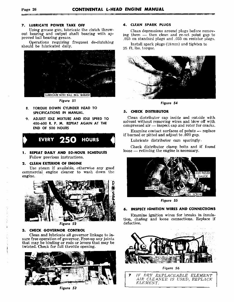
7. LUBRICATE POWER TAKE OFFUsing grease gun, lubricate the clutch throw-
out bearing and output shaft bearing with ap-proved ball bearing grease.
Operations requiring frequent de-clutchingshould be lubricated daily.
4. CLEAN SPARK PLUGS
Clean depressions around plugs before remov-ing them -- then clean and re-set point gap to.025 on standard plugs and .035 on resistor plugs.
Install spark plugs (18mm) and tighten 35 ft. Ibs. torque.
Figure 5!
TORQUE DOWN CYLINDER HEAD TOSPECIFICATIONS IN MANUAL.
ADJUST IDLE MIXTURE AND IDLE SPEED TO400-600 R. P. M. REPEAT AGAIN AT THEEND OF 500 HOURS
2e
commercialengine.
REPEAT DALLY AND SO-HOUR SCHEDULESFollow previous instructions.
CLEAN EXTERIOR OF ENGINEUse steam if available, otherwise any good
engine cleaner to wash down the
Figure 52
3. CHECK GOVERNOR CONTROLClean and lubricate all governor linkage to in-
sure free operation of governor. Free-up any jointsthat may be binding or rods or levers that may betwisted. Check for full throttle opening.
Figure 54
5. CHECK DISTRIBUTOR
Clean distributor cap inside and outside withsolvent without removing wires and blow off withcompressed air -- inspect cap and rotor for cracks.
Examine contact surfaces of points -- replaceif burned or pitted and adjust to .020 gap.
Lubricate distributor cam sparingly.
Check distributor clamp bolts and if foundloose -- retiming the engine is necessary.
Figure 55
6. INSPECT IGNITION WIRES AND CONNECTIONS
Examine ignition wires for breaks in insula-tion, chafing and loose connections. Replace ifdefective.
Figure 53
7
Figure 56
IF DRY REPLACEABLE ELEMENTAIR CLEANER IS USED, REPLACEELEMENT.

CONTINENTAL L-HEAD ENGINE MANUAL Page 27
EVERY 500 HOURS
I. REPEAT DAILY u 50 HOUR AND 250 HOURSCHEDULES
2. COOLING SYSTEMClean radiator core by blowing out with com-
pressed air.Inspect radiator mounting.Inspect water pump and connections for leaks.Check fan and accessory drive belts.
4. CARBURETORClean exterior and check mounting to manifold.Adjust carburetor air adjustment for even
running and adjust idle speed to 400-600 R.P.M.minimum.
..Inspect throttle and choke liflkage for freeoperation.
Figure 59 m Carburetor
FUEL PUMPClean Filter bowl and screen.Inspect mounting and gasket.Check all connections for leaks.
Figure 57
3. ADJUST VALVE TAPPET CLEARANCECheck and adjust intake and exhaust valve
tappets to following clearances at idling speed andrunning temperature:
Figure 60reFuel Pump Mounting
6. MAGNETO (when equipped)Spark test with engine operating by checking
firing with each high tension cable held about1/16" away from spark plug terminal.
Figure 58--Adjusting Valve Tappet Clearance
MODEL INTAKE EXHAUST
F227, F245 .012 .020M330, M363 .017 .020B427 .017 .022
Please check your enginerect setting.
nameplate for the cor-
NOTE: Tappet settlng:~ for previous models are listed on pages
Figure 61Remove end cap and examine carbon brushes
for free-movement and inspect breaker points forwear and gap. Gap should be .015.
7. SAFETY AND THERMAL CONTROLSInspec*~ control wires and connections.Examine armored capillary tubing on water
temperature element for visual damage that maycause faulty operation.
8. ADJUST IOLE MIXTURES AND IDLE SPEEDTO 400-600 R. P. M.

Page 28 CONTINENTAL L-HEAD ENGINE MANUAL
SECTION VCOOLING SYSTEM
The function of the cooling system is to preventthe temperatures in the combustion chamber,which may reach as high as 4000 ° F., from damag-ing the engine and at the same time keep the op-crating temperatures within safe limits.
Maintaining the cooling system efficiency is im-portant, as engine temperatures must be broughtup to and maintained within satisfactory range forefficient operation; however, must be kept fromoverheating, in order to prevent damage to valves,pistons and bearings.
CONTINENTAL L-HEADCOOLING SYSTEM
With the exception of some "N" and a few "Y"engine specifications, all .Continental L-Head en-gines have the cooling water force-circulated by awater pump and use a thermostat and by-pass sys-tem to control the temperature range.
Some of the "N" and a few of the "Y" specifica-tions circulate the cooling water using the Thermo-Syphon system -- which requires no water pumpor thermostat -- but circulates the water from theresulting liquid expansion when heated and con-traction during cooling.
The coolant from the water pump is first directedin the block against the exhaust valve seats andinto passages connecting the cylinder head. Thismethod provides the coldest water reaching theparts subjected to the highest temperatures.
The cylinder walls, in turn, are cooled their fulllength by convection currents only, which kee)s
P~DI~TOR FILLER CAP
RADIATOR~
THERMOSTAT
RADIATOR
ENGINE
Figure 62 ~ ThermostatFlow Control
Thermostat Closed, Wa-ter Re-Circulating through
Engine ONLY
Thermostat Open, WaterCirculating through BOTH
Engine and Radiator
Figure 63 ~ Water Pump
the cylinder barrels at a more uniform temperatureand thereby reduces crankcase oil dilution andsludge formation.
Upon leaving the cylinder head, the water entersthe thermostat housing, in which is mounted theby-pass type thermostat, which controls the open-ing to the radiator or heat exchanger. Upon beingdischarged from the thermostat housing, the waterenters the radiator or heat exchanger, dependingupon the application, where it is cooled before re-entry into the engine.
Continental L-Head gasoline engines operatemost efficiently with water temperatures of 180°-200° F. and a thermostat and by-pass system isgenerally used to control these temperatures.
The thermostat valve remains closed and onlyallows the water to recirculate within the engineitself until normal operating temperatures arereached. This provides for both rapid and eventemperature increase of all engine parts during thewarm-up period. When desired temperature isreached, the thermostat valve opens and allows thewater to circulate through both the engine andradiator.
IMPORTANTPresent thermostats begin to open at 180° F. and are fully open at 202°F. Operation of engines in this temperature range is not harmful. How-ever, temperature gauges are not always exactly accurate and may some-times indicate higher than actual temperature. This can lead operatorsto believe engines are overheating when they are actually operatingnormally.Overheating is always accompanied by loss of coolant water. In case ofdoubt, this should be checked.
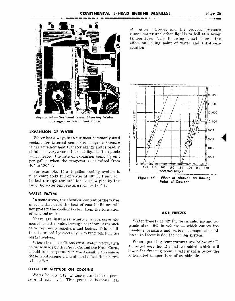
CONTINENTAL L-HEAD ENGINE MANUAL Page 29
~ ~ at higher altitudes and the reduced pressurecauses water and other liquids to boil at a lower
~ temperature. The following chart shows the~ effect on boiling point of water and anti-freeze~ ~ solution
16, 000
__.. .e n - I0~ 000
Water has always been the most commonly usedcoolant for internal combustion engines becauseit has excellen~ heat transfer ability and is readily / ~4000obtained everywhere. Like all liquids it expandswhen heated, the rate of expansion being ~ pint ~~0ooper gallon when the ~emperature is raised from40° to 180° F. ~ 0~ 220 210 200 190 180 170 160 150
For example: If a 4 gallon cooling system is BOIL~G PO~filled completelF full of water at 40° F, 1 pint will Figure 65 ~ Effect of Altitude on Boilingbe lost through the radiator overflow pipe by the Point of Coolanttime the water temperature reaches 180° F.
WATER FILTERS
In some areas, the chemical content of ~he wateris such, that even the best of rust inhibitors willnot protect the cooling system from the formationof rust and scale.
There are instances where this corrosive ele-ment has eaten holes through cast iron parts suchas water pump impellers and bodies. This condi-tion is caused by electrolysis taking place in theparts involved.
Where these c, onditions exist, water filters, suchas those made by the Perry Co. and the Fram Corp.,should be incorporated in the assembly to removethese troublesome elements and offset the electro-lyric action.
ANTI-FREEZES
Water freezes at 32° F., forms solid ice and ex-pands about 9% in volume -- which causes tre-mendous pressure and serious damage when al-lowed to freeze inside the cooling system.
When operating temperatures are below 32° F.an anti-freeze liquid must be added which willlower the freezing point a safe margin below theanticipated temperature of outside air.
EFFECT OF ALTITUDE ON COOLING
Water boils at: 212° F under atmospheric pres-s~,re at sea level. This pressure becomes less

Page 30 CONTINENTAL L-HEAD ENGINE MANUAL
OPERATING TEMPERATURE RANGETYPES OF ANTI-FREEZE
PLAIN ALCOHOL -- (evaporates da~ily)
METHYL ALCOHOL COMPOUNDS ...........................................
ETHYLENE GLYCOL(permanent type) -- When ,there are no leaks addwater only to make up for evaporation .........................
32° to 10°F ~-10°to-10°F
Not Recommended w/180°
Not Recommended w/180°
1 to4 2to5
--10 ° to--30 ° F
Thermostat
Thermostat
ltol
NOTE: While the above list includes threetypes of generally used Anti-Freeze, the Eth-
ylene Glycol or Permanent Type will be found
to be the most desirable and likewise themost economical because of the temperaturesdesirable to maintain for efficient operation.
that of the fan circulated air, will serve to keepthe cooling surfaces of the core free of dirt andother particles.
Every 500 hours of operation the radiator andcooling system should be well cleaned and flushedwith clean water. (See Radiator Drain.)
CORROSION INHIBITORS
Water forms rust due to its natural tendencyto combine chemically with iron and air in thesystem. Rust inhibitors for water are inexpen-sive, simple to use and make cleaning and flush-ing necessary only after long periods of opera-tion.
The most commonly used is either a 3 % addi-tion of soluble oil or commercial corrosion inhibi-tor that is readily available at low cost. The addi-tion of corrosion inhibitor is not necessary if ananti-freeze containing a rust inhibitor is used.
RADIATOR
The radiator or heat exchanger consists of aseries of copper tubes through which the coolingwater is circulated. In standard radiator designfins are connected to the copper tubes to give anextended surface through which heat can be dis-sipated. It is important that these tubes be keptclean on the inside and the fins free of dirt on theoutside so that maximum heat transfer can takeplace in the radiator.
Blowing out between the fins of the radiator,using compressed air, in a direction opposite to
Figure 66 ~ Radiator Drain
Wherever possible, only soft clean water shouldbe used in the cooling system. Hard water willcause scale to form in the radiator and the enginewater jackets and cause poor heat transfer. Wherethe use of hard water cannot be avoided an ap-proved water softener can be used.
CLEANING COOLING SYSTEM
Deposits of sludge, scale and rust on the coolingsurfaces prevent normal heat transfer from themetal surfaces to the water and in time render the

CONTINENTAL L-HEAD ENGINE MANUAL Page 31
cooling system ineffective to properly maintainnormal operating temperatures. The appearanceof rust in the radiator or coolant is a warning thatthe corrosion inhibitor has lost its effectivenessand should be cleaned before adding fresh coolant.
Dependable cleaning compounds should be used.Follow the procedure recommended by the sup-plier. This is of prime importance because differ-ent cleaners vary in concentration and chemicalcompositions. After cleaning and flushing, thesystem should be filled with an approved anti-freeze compound containing a rust and corrosioninhibitor or water with a corrosion inhibitor.
REVERSE FLOW FLUSHING
Whenever a cooling system is badly rust-cloggedas indicated by overflow loss or abnormally highoperating temperatures, corrective cleaning by re-verse flow flushing will most effectively removethe heavy deposits of sludge, rust and scale. Thereverse flow flushing should be performed imme-diately after draining the cleaning solution and itis advisable to flush the radiator first, allowing theengine to cool as much as possible.
Reverse flush the radiator, as follows:
1. Disconnect the hoses at the engine.
2. Put radiator cap on tight.
3. Clamp the flushing gun in the lower hosewith a hose clamp.
CLOSED
HOSE
GUN
AIR
Figure 67--Reverse Flushing Radiator
4. Turn on the water and let it fill the radiator.
5. Apply air pressure gradually, to avoid radi-ator damage.
6. Shut off the air, again fill the radiator withwater and apply air pressure--repeat until theflushing stream runs out clear.
7. Clean and inspect radiator cap.
To Reverse flush the engine water Jacket
1. Remove the thermostat.
2. Clamp the flushing gun in the upper hose.
3. Partly close the water pump opening to fillthe engine jacket with water before applyingthe air.
4. Follow the same procedure outlined abovefor the radiator by alternately filling the waterjacket with water and blowing it out with air(80# pressure) until the flushing stream is clear.
WATER~ ~ FLUSHING GUN
Figure 68- Reverse Flushing Engine
TESTING THERMOSTAT
Remove Water Pump Header as shown in illus-tration. Before testing, clean and examine the bel-lows for rupture or distortion. If the valve canbe pulled or pushed off its seat with only a slighteffort when cold or it does not seat properly, theunit is defective and should be replaced.
The thermostatic operation can be checked inthe following method :
1. Hang thermostat by its frame in a containerof water so that it does not touch the bottom.
2. Heat the water and check temperature witha thermometer.

Page 32 CONTINENTAL L-HEAD ENGINE MANUAL
3. If the valve does not start to open at tem-peratures of 180°-200° F. or if it opens well beforethe 180° point is reached the thermostat shouldbe replaced.
THERMOSTAT
Figure 69--Checking Thermostat
Figure 70 m Replacing Thermostat
RADIATOR PRESSURE CAP
Many operations use a pressure cap on the radi-ator to prevent overflow loss of water duringnormal operation. This spring loaded valve in thecap closes the outlet to the overflow pipe of theradiator and thus seals the system, so that pres-sure developing within the system raises the boil-ing point of the coolant and allows higher tempera-tures without overflow loss from boiling. Mostpressure valves open at 41/2 or 7 pounds, allowingsteam and water to pass out the overflow pipe,however, the. boiling point of the coolant at thispressure is 224°F or 230°F at sea level. When apressure cap is used an air tight cooling system isnecessary with particular attention to tight con-nections and a~ radiator designed to witl~stand theextra pressure.
When replacing the thermostat in the wateroutlet elbow, be sure seal is in place, and seal seatas well as the counterbore is clean.
Assemble new gasket to pump body or spacer.Thermostat flange must seat in counterbore withgasket sealing contact between it and the pumpbody.
PRESSUI~E CAP SEAL CONTACT
GASKET
GASKET SEAT
Figure 71 ~
CONTINENTAL L-HEAD ENGINE MANUAL Page 33
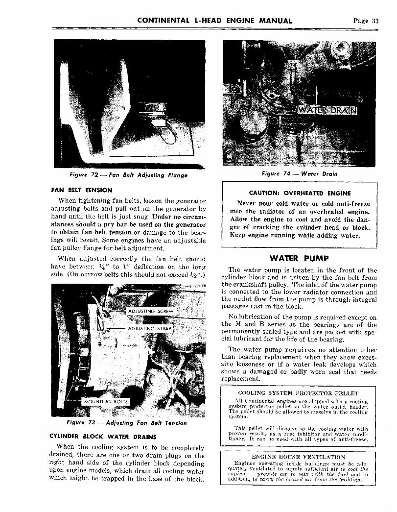
Figure 72 m Fan Belt Adjusting Flange
FAN BELT TENSION
When tightening fan belts, loosen the generatoradjusting bolts and pull out on the generator byhand until the belt is just snug. Under no circum-stances should a pry bar be used on the generatorto obtain fan belt tension or damage to the bear-ings will result. Some engines have an adjustablefan pulley flarlge for belt adjustment.
When adjusted correctly the fan belt shouldhave betweer~ :~/4/’ to 1" deflection on the longside. (On narrow belts this should not exceed
Figure 73--Adjusting Fan Belt Tension
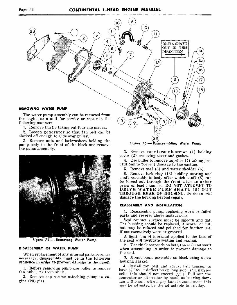
CYLINDER BLOCK WATER DRAINS
When the cooling system is to be completelydrained, there are one or two drain plugs on theright hand side of the cylinder block dependingupon engine models, which drain all cooling waterwhich might be trapped in the base of the block.
Figure 74--Water Drain
CAUTION: OVERHEATED ENGINE
Never pour cold water or cold anti-freezeinto the radiator of an overheated engine.Allow the engine to cool and avoid the dan-ger of cracking the cylinder head or block.Keep engine running while adding water.
WATER PUMPThe water pump is located, in the front of the
cylinder block and is driven by the fan belt fromthe crankshaft pulley. The inlet of the water pumpis connected to the lower radiator connection andthe outlet flow from the pump is through integralpassages cast in the block.
No lubrication of the pump is required except onthe M and B series as the bearings are of thepermanently sealed type and are packed with spe-cial lubricant for the life of the bearing.
The water pump requires no attention otherthan bearing replacement when they show exces-sive looseness or if a water leak develops whichshows a damaged or badly worn seal that needsreplacement.
COOLING SYSTEM PROTECTOR PELLETAll Continental engines are shipped with a cooling
system protector pellet in the water outlet header.The pellet should be allowed to dissolve in the coolingsystem.
This pellet will dissolve in the cooling water withproven results as a rust inhibitor and water condi-tioner. It can be used with all types of anti-freeze.
ENGINE HOUSE VENTILATIONEngines operating inside buildings must be ade-
qua.rely ventilated to supply sufficient air to cool theengine -- provide air to mix with the fuel and inaddition, to carry the heated air from the building.
Page 34 CONTINENTAL L-HEAD ENGINE MANUAL
DRIVE SHA FTOUT IN THISDIRECTION
REMOVING WATER PUMP
The water pump assembly can be removed fromthe engine as a unit for service or repair in thefollowing manner:
1. Remove fan by taking out four cap screws.2. Loosen generator so that fan belt can be
slacked off enough to slide over pulley.3. Remove nuts and lockwashers holding the
pump body to the front of the block and removethe pump assembly.
Figure 75--Removing Wafer Pump
DISASSEMBLY OF WATER PUMP
When replacement of any internal parts becomesnecessary, disassembly must be in the followingsequence in order to prevent damage to the pump.
1. Before removing pump use puller to removefan hub (17) from shaft.
2. Remove cap screws attaching pump to en-gine (20) (21).
Figure 76-- fssembling Water Pump
3. Remove countersunk screws (1) holding"cover (2) removing cover and gasket.
4. Use puller to remove impeller (4) taking pre-cautions to prevent damage to the casting.
5. Remove seal (5) and water shedder (6).6. Remove lock ring (13) holding bearing and
shaft assembly in body after which shaft (8) canbe forced out through the front with an arborpress or lead hammer. DO NOT ATTEMPT TODRIVE WATER PUMP SHAFT (8) OUTTHROUGH REAR OF HOUSING. To do so willdamage the housing beyond repair.
REASSEMBLY AND INSTALLATION
1. Reassemble pump, replacing worn or failedparts and reverse above instructions.
Seal contact surface must be smooth and flat.The bushing should be replaced, if scored or ~ut,but may be refaced and polished for further use,if not excessively worn or grooved.
A light film of lubricant applied to the face ofthe seal will facilitate seating and sealing.
2. Use thick soapsuds on both the seal and shaftwhen assembling in order to prevent damage tothe seal.
3. Mount pump assembly on block using a newhousing gasket.
4. Install fan belt and adjust be~t tension tohave :~/~," to 1" deflection on long side. (On narrowbelts this should not exceed ~,/~".) Pull out thegenerator or alternator by hand, as bearing dam-age will result with a pry bar; in some cases thismay be adjusted by the adjustable fan pulley.

CONTINENTAL L-HEAD ENGINE MANUAL Page 35
SECTION VIFUEL SYSTEM
The basic purpose of the fuel system is to store,convey, mix fuel with air, then vaporize and intro-duce the mixture into the engine.
Fuel is stored in the gasoline tank; it is filteredand flows through the fuel supply line to the carbu-retor- either by gravity or under pressure of afuel phmp. The carburetor mixes the fuel withproper proportions of air and at the same timebreaks it into very fine spray particles. This atom-ized spray changes to vapor, by absorbing heat asit travels through the intake manifold to the com-bustion chamber. Fuel must be vaporized since itwill not burn well as a liquid.
GRAVITY FUEL SYSTEMThis is the most simple fuel system and is gen-
erally used on power units as it eliminates the needof a fuel pump--it only requires the fuel tanklocated higher than the carburetor.
I~ .METAL EDGETYPE FILTER
Figure 77--Edge Type FilterAll power units with fuel tank have a combina-
tion shut-off valve and an efficient metal edge typefilter. This filter prevents all foreign particles andwater from entering the carburetor.
With reasonable care in filling the tank withclean fuel, this filter will require only seasonalcleaning of both the filter and tank.
CAUTION:IT IS RECOMMENDED THAT THIS VALVEBE KEPT IN THE CLOSED POSITION EX-CEPT WHEN UNIT IS IN OPERATION.
MECHANICAL FUEL PUMPThe Mechanic, al Fuel Pump is generally used
when the fuel supply is below the level of the car-buretor. They are of several models dependentupon the diaphragm diameter and assembly ar-rangement with fuel strainer bowl, air dome andmanual primer.
Figure 78 ~ Fuel PumpThis mechanical fuel pump mounts on the cylin-
der block pad and is driven by an eccentric on theengine camshaft contacting the fuel pump rockerarm.
Constant fuel pressure is maintained by an airdome and a pulsating diaphragm operated and con-trolled by linkage which adjusts itself to pressuredemands.
Fuel Pump Tests -- The fuel pressure may bemeasured by installing the pressure gauge betweenthe fuel pump and carburetor.
The AC fuel pump size and static pressures @1800 R.P.M for the L-Head engines are.
ENGINE DIAPHRAGMMODEL DIAMETER FUEL PRESSURE
NYFMB
2~’/2 - 2,2#
3 - 4V2#
MAX.LIFT
When pressures are below the range, pumpshould be’ disassembled and reconditioned with thespecial overhaul kits available.
Maintenance -- Fuel pump trouble is of only twokinds ~ either the pump is supplying too little gasor, in rare cases, too much.
If the pump is supplying too little gas, the engineeither will not run or it will cough and falter. Iftoo much gas- it will not idle smoothly or youwill see gasoline dripping from the carburetor,
If the engine is getting too little gas -- the trou-ble may be in the pump, fuel line or the gas tank.First, be sure there is gas in the tank, then dis-connect the pump to carburetor line at the pump orcarburetor, and turn the engine over a few timeswith the ignition off. If gas spurts from the pumpor open end of the line--the pump, gasoline andtank are OK.

Page 36 CONTINENTAL L-HEAD ENGINE MANUAL
Figure 79 ~ Checking F~el Pressure
If there is little or no Flow--check the following:1. Look for leaky bowl gasket or line connec-tions -- tighten them.2. Remove and clean with solvent the gasstrainer or screen inside the pump bowl.3. Look for clogged fuel line--Blow out withcompressed air.4. Make sure that all pump cover screws andexternal plugs are tight.5. Inspect flexible fuel line for deterioration,leaks, chafing, kinks or cracks. If none of theseitems restore proper flow--remove the pumpfor replacement or overhaul.
If getting too much gas -- an oversupply of gas-oline is generally caused by trouble other than thefuel pump -- so first check the following :
1. Defective Automatic Choke.2. Excessive use of hand choke.3. Loosely connected fuel line, or loose carbu-retor assembly screws.4. Punctured carburetor float.5. Defective carburetor needle valve.6. Improper carburetor adjustment.If none of these items corrects flooding, remove
the fuel pump for replacement or overhaul.
ELECTRIC FUEL PUMPMany L-Head engines use electric fuel pumps
operated from the storage battery supply. Thepump should be mounted close to the fuel tankso as to provide fuel pressure at all points alongthe fuel line and so eliminate vapor lock.
The electric fuel pump is energized in the igni-tion circuit--which assures quick filling of thecarburetor and fuel lines to effect easy starting.
When fuel pump trouble is suspected, disconnectthe fuel line at the carbm’etor and turn on theignition switch. Pump fuel into a small container,then place your finger on the outlet side of the fuelline. If th~ pump stops or ticks very infrequently,the pump and fuel line connections are satisfactory.Remove your finger from the outlet side of the fuel
line and if ample fuel flows--the pump is satis-factory.
If fuel does not flow and all connections are tight,the pump should be replaced or repaired. Alwaysbe sm’e of a good ground and check for faulty flexi-ble fuel lines and poor electrical connections.
CARBURETORContinental L-Head gasoline engines normally
use various models of Zenith and Marvel-Scheblercarburetors- of both the updraft and downdrafttypes.
The carburetor mixes fuel with air and metersthe mixture into the engine as the power is de-manded. Most carburetors incorporate the follow-ing systems to provide the flexibility and sensitiverequirements of varying loads and conditions:
1 -- Float System -- Controls the level and sup-ply of fuel.2- Idle or Low Speed- Furnishes the propermixture for the engine idle, light load and slowspeeds, until the main metering systemfunctions.3- Main Metering System- Controls the fuelmixture from part throttle operation to wideopen throttle.4 -- Power or Economizer System -- Provides aricher mixture for maximum power and highspeed operation. This system ceases to functionwhen the manifold vacuum is above 6" Hg.5--Compensating System--Provides a mix-ture which decreases in richness as the air speedincreases.6 -- Choke System -- Delivers additional fuel tothe manifold for cold engine starting.
ZENITH CARBURETORThe Zenith 62 Series carburetor shown below
has the following three adjustments:1- Main Adjustment Screw--Determines theamount of fuel which may be obtained for highspeed operations.
Figure 80 ~Zenith 62 Series Carburetor
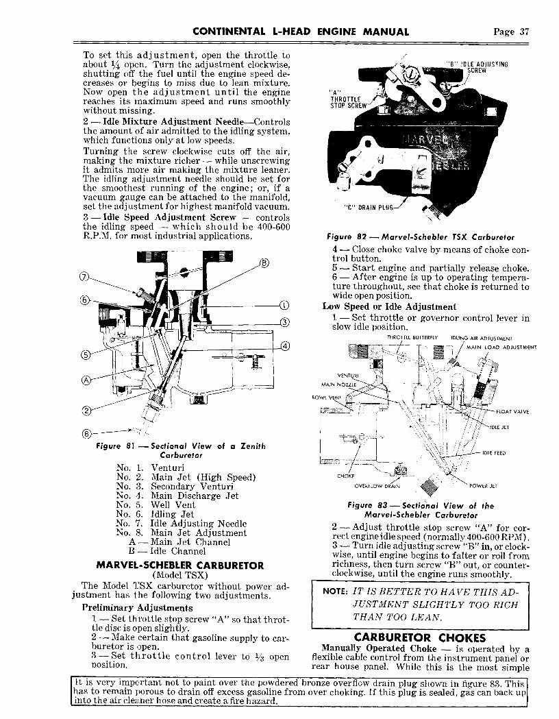
CONTINENTAL L-HEAD ENGINE MANUAL Page 37
To set this adjustment, open the throttle toabout 1/~ open. Turn the adjustment clockwise,shutting off the fuel until the engine speed de-creases or begins to miss due to lean mixture.Now open the adjustment until the enginereaches its maximum speed and runs smoothlywithout missing.2- Idle Mixture Adjustment Needle--Controlsthe amount of air admitted to the idling system,which functions only at low speeds.Turning t:he screw clockwise cuts off the air,making the mixture richer--while unscrewingit admits more air making the mixture leaner.The idling adjustment needle should be set forthe smoothest running of the engine; or, if avacuum gauge can be attached to the manifold,set the adj~stment for highest manifold vacuum.3--Idle Speed Adjustment Screw -- controlsthe idling speed -- which should be 400-600R.P.M. for most industrial applications.
Figure 81’--Sectional View of a ZenithCarburetor
No. 1. VenturiNo. 2. Main Jet (High Speed)No. 3. Secondary VenturiNo. 4. Main Discharge JetNo. 5. Well VentNo. 6. Idling JetNo. 7. Idle Adjusting NeedleNo. 8. Main Jet Adjustment
A--Main Jet ChannelB -- Idle Channel
MARVEL-SCHEBLER CARBURETOR(Model TSX)
The Model ~:SX carburetor without power ad-justment has the following two adjustments.
Preliminary Adjustments1 -- Set throttle stop screw "A" so that throt-tle disc is open slightly.2 --Make certain that gasoline supply to car-buretor is open.3--Set throttle control lever to 1/~ openposition.
IDLE ADJUSTING,SCREW
THROTTLESTOP
"C" DRAIN
Figure 82 ~MarveI-Schebler TSX Carburetor
4 ~ Close choke valve by means of choke con-trol button.5- Start engine and partially release choke.6- After engine is up to operating tempera~ture throughout, see that choke is returned towide open position.
Low Speed or Idle Adjustment1- Set throttle or governor control lever inslow idle position.
THROTTLE BUTTERFLY IDLING AIR ADJUSTMENT
MAIN LOAD ADJUSTMENT
VENTURI
MAIN
VALVE
NOTE:IT IS BETTER TO HAVE THIS AD-JUSTMENT SLIGHTLY TOO RICHTHAN TOO LEAN.
CARBURETOR CHOKESManually Operated Choke ~ is operated by a
flexible cable control from the instrument panel orrear house panel. While this is the most simple
shown in figure 83. This JIt is very important not to paint over the powdered bronze overflow drain plug is sealed, gas can back uplJhas to remain porous to drain off excess gasoline from over choking. If this pluginto the air cleaner hose and create a fire hazard. I

Page 38 CONTINENTAL L-HEAD ENGINE MANUAL
type, it is most important that the operator havethe choke valve in wide open position when engineoperating temperature is reached.
ZENITH ELECTRIC CHOKE CONTROLIs made as part of the carburetor assembly. It
is directly connected to the choke shaft and auto-matically controls the opening during the entireengine operation.
VACUUM PISTON CHOKE PLATE
.~ I~< ~ ~ ~oL~
VACUUM C~NN~L ~WHEN SANDWICHTYPE GOVE~OROPENING
IS USED
Figure 84--Zenith Electric ~hoke
Manifold vacuum is used to open the choke shaftpartially after the initial firing of the engine, andheat is used on the thermostat spring to control theamount of opening during the warming up period.This heat is provided by an electric element in thethermostat chamber. Fast idling during the warm-up period is also provided by a throttle advancemechanism which is actuated from the choke shaft.
The heating element which is energized whenthe ignition is "on" gradually warms the thermo-stat, decreasing its resistance to the pull of thevacuum piston, which gradually causes the choketo open and moves the throttle advance to thewarm idle position.
All units are initially set with the thermostat 15notches rich for 70° F. ambient temperature. Tem-perature corrections can be made by allowing onenotch on the cover for each 5 degrees variation ~making certain that the choke valve is fully openwhen operating temperatures are reached.
51SSON AUTOMATIC CHOKEUses an electro-magnet and a thermostat to
automatically close the carburetor choke valve forcold starring and regulates its degree of openingas the engine warms.
The unit is mounted on the exhaust manifold anda small rod connects it to the carburetor Chokelever. The electro-magnet is energized by thestarter circuit which pulls an armature lever down,closing the choke valve.
As soon as the engine starts, the electro-magnetcircuit is broken and H~en the thermostat providesautomatic adjusting of the choke valve during thewarming-up period.
The carburetor choke lever should be adjustedso that when the carburetor choke valve is closed
tight, there will be .015" to .020" clearance betweenthe automatic choke lever and the field pole thatserves as a stop. This measurement is taken at "A"and must be made with thermostatic control "B"pushed down as far as it will go.
C~-. ~. B TO STARTER SWITCH
Figure 8$--Sisson Automatic Choke
CAUTION: Do not oil the Sisson automatic
choke under any circumstance.
Carburetor Service- In general any change incarburetor action will usually come gradually,therefore, if the carburetor operated satisfactorilywhen last used, it can reasonably be assumed thatsome other part of the engine is at fault- whichshould be corrected before disturbing thecarburetor.
Dirt is the main enemy of good carburetion asit fills up the minute air and gasoline passages andaccelerates the wear of delicate parts.
Never use a wire to clean out restrictions in jetsas this will destroy the accurate calibrations ofthese parts -- always use compressed air. The jetsare made of brass to prevent rust and corrosionand a wire would cut or ream the hole in the jet andruin it.
Maintaining correct fuel level in the carburetorbowl is important--as the fuel flow through thejets is naturally affected by the amount of fuel inthe bowl.
After a carburetor has been in service for sometime, the holes in the jets and the float valve andseat become worn from the constant flow of fuelthrough them and should be overhauled by a com-petent carburetor service station.
Do not experiment with other size jets or anyso-called fuel-saving gadgets as your arrangementhas been thoroughly tested on a dynamometerprogram.
GOVERNORSThe governor is a device which controls engine
speed- either keeping it operating at a constantspeed or preventing it from exceeding a predeter-mined speed. It promotes engine operation econ-omy and eliminates needless engine failures.
Continental L-Head engines use many types ofvelocity and centrifugal governors -- however themajority use centrifugal (Mechanical) governors.

CONTINENTAL L-HEAD ENGINE MANUAL Page 39
VELOCITY GOVERNORSVelocity Governors -- are generally used to pre-
vent engine speed from exceeding a predeterminedmaximum. The governor is mounted between thecarburetor .and manifold flanges, in its most simpleform, it consists of a main body, which contains athrottle shaft, a throttle valve and a main governorspring. The main governor spring is attached bylinkage to the governor shaft and the spring forceholds the throttle valve open.
When the engine is started, air flows throughthe carburetor throat and the governor throat.The velocity of the air creates a pressure above thethrottle valve. When this pressure exceeds theforce exerted by the spring, the throttle will movetoward a closed position. The adjusting screwvaries the spring tension.
Figure 87 ~ Governor Linkage
Figure 86 ~ Hoof Velocity GovernorWhen thi:~ closing action of the valve exactly
balances the spring, governing action takes placeand m~ximum speed is fixed at this point.
When load is applied--the engine speed tendsto drop -- the velocity of the gas through the man-ifold and the pressure against the governing valveis reduced and the spring opens the valve to feedmore gasoline to the engine to handle the increasedload demand. Thus an almost constant speed ismaintained whether the engine is runni~g with orwithout load.
CHECKING AND ADJUSTINGGOVERNOR LINKAGE
The following is a step by step procedure to fol-low in checking and adjusting the governorlinkage :
1 -- With the engine stopped and spring tensionabout normal, the governor should hold thethrottle in the open position. The governorto carburetor control rod should be adjustedin length so the throttle stop lever is ~4 to½,~ off the stop pin.
2--Make certain that all linkage is free withspring at operating tension disconnect thegoverrtor spring and check movement oflevers and rods.
3--The hinged lever governor eliminates theneed for a spring loaded throttle lever onthe carburetor. As the carburetor lever isforced to idle position by the speed controllever, this in turn pivots the top half ofthe governor arm forward, slowing the en-gine to idle. (See Figure 87.)
CONTINENTAL GOVERNORSThe Continental Governor -- is used on most
industrial units requiring normal industrial speedregulation. These governors differ from conven-tional centrifugal governors mainly in that roundsteel balls are used as the motivating force pro-ducer instead of masses of weight.
When the governor is driven at increasing speedsby the engine through the governor gear, the hard-ened steel, balls, move outward, forcing the conicalupper race, fork base, fork and lever assemblytoward a closed throttle position.
An externally mounted spring imposes tensionon the lever assembly toward the open throttleposition. As the engine speed increases, the centri-fugal force created by the balls will increase untila balanced condition between the governor forceand the spring force exists and the governing leverremains stationary--holding a constant engineR.P.M.
Adjustment- The desired engine speed is ob-tained by increasing or decreasing the governorspring tension.
WARNING.IDisconnect Fan before making Governor adjustments
CONSTANT SPEED GOVERNOR1- Start the engine. While it is warming up,
back out surge adjusting screw "C" (Figure88) so it will have no effect.
2- With engine warmed up, adjust idle speedapproximately 150 R.P.M. higher than therequired speed under load, by turning screw"B" in or out, thus either increasing or de-creasing pull on the spring.Lock screw "A" should be backed out so asnot to interfere with the adjustment.
3 -- Apply the desired load, and readjust screw"B" in order to obtain the required speedunder load.Release load and note R.P.M. at which en-gine settles out.Again apply load, and observe the drop inR.P.M. before governor opens throttle tocompensate.

Page 40 CONTINENTAL L-HEAD ENGINE MANUAL
The range of a governor’s action is indicatedby the differential between R.P.M. underload and that under no load.This can be rallied and the sensitivity ofgovernor changed by changing the lengthof screw "n".To broaden the range of the governor andproduce a more stable action, lengthenscrew "E" and compensate for this changeby turning.screw "B" in to restore speed.Lengthening screw "E" changes pull onspring to more nearly the arc of the leveraction, thus having the effect of increasing~he spring rate.
GOVERiXSPR~NG I~
D ~ SURGE ADJ.SCREWC
SPEED ADJ.LOCKING SCREW
A
SPEED ADJ. SCREW BFigure 88-- Governor
6 -- To narrow the range and increase the sensi-tivity of the governor, reverse procedureoutlined in 5. (Changing the length of screw"E" has the same effect as usinga strongeror weaker spring.)
7 -- With the governor adjusted for desired per-formance, release the load and allow engineto run at governed speed, no load. If asurge is noted, turn surge adjusting screw"C" in or clockwise un.til surge is elimi-nated. Do not turn in ~urther than neces-sary as it may make it difficul.t to get a lowenough slow idle.Alternate method if a tachometer is used:have engine running at high idle (governedspeed) no load. Turn surge adjusting screwin until R.P.M. increases 10-20 R.P.M. andlock. If linkage and carburetor are allproperly adjusted, surge will be gone.
8--When governor adjustment is completed,tighten locking screw "A", which locks thecam in position. Then make sure that alllock nuts are tight, in order to maintain theadjustment.
VARIABLE SPEED GOVERNOR1 -- Back Out Surge Screw "1" -- until only 3-4
threads hold -- then lock with lock nut "2".2- Start Engine and Idle- until warmed to
operating temperature.3--Set Specified High Idle No-Load Speed-
by moving throttle to required position andadjusting high speed screw "3".
Variable-Speed Governor
4- Check Regulation- by applying and re-moving engine load.(1) If regulation is too broad -- increase
spring tension with sensitivity screw"4" and readjust high speed screw"3" throttle stop to obtain high idlespeed.
(2) If regulation is too narrow -- decreasespring tension with sensitivity screw"4" and readjust high speed screw"3" throttle stop to obtain desiredhigh idle speed.
(3) If governor surges under load--de-crease spring tension with sensitivityscrew "4" and readjust throttle leverposition to desired high idle speed.
(4) Repeat above steps as required--un-til desired performance is obtained.When adjustment is complete, lock alllock nuts to maintain settings.
Surge Screw "1"--is used to removea no-load surge only
If governor surges at no-load, turn surgescrew in a turn at a time until the surge isremoved. Do not turn in far enough to in-crease the no-load speed more than a fewRPM, if at all.
Maintenance- The slotted driver, in which theballs move, is pinned to the governor shaft; thetwo races are free floating on the shaft. When theengine is running at a fixed speed all parts goaround with the governor shaft and the thrust istaken on the thrust bearing between conical shapedrace and fork base. When a change in speed, dueto change in load, takes place, the relative speedbetween the balls and races is changed. Conse-quently, wear is distributed over the entire operat-ing surface of the races and balls. Since the sur-faces are hardened, little or no wear other than apolish should ever take place on these parts.
The driver must always be tight to the shaft.The races must be free on the shaft.
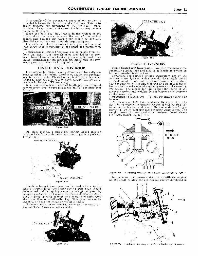
CONTINENTAL L-HEAD ENGINE MANUAL Page 41
In assembly of the governor a space of .004 to .006 isprovided betweer~ the driver and ~he flat race. This is toassure freedom for movement of the flat race. Whenservicing the governor, make sure that both races revolvefreely on the shaft.
When t’he balls are "in", that is in the bottom of thedriver slots, the space between the top of the conicalshaped race bustring and hairpin clip should be .230-.240.Use .010 spacer washers to obtain required space.
The governor shaft is pressed into gear and securedwith screw that is partially in the shaft and partially ingear.
Lubrication is supplied the governor by splash from thefront end gear train through holes provided in the gov-ernor base. Like all mechanical governors, it must haveample lubrication for its functioning. Make sure the g’ov-ernor parts are being well supplied with oil.
HINGED LEVER GOVERNORThe Continental hinged lever governors are basically the
same as other Continental Governors, except the governorarm is in two parts. Pivoted on a pivot bolt, it is springloaded to hold the arm in a straight position except whenlow idle is desired. (Figure 88A.)
When carburetor lever is forced to 1die position by speedcontrol lever, this in turn pivots top half of governor armforward.
COIL SPRING (2.)
Figure 88A
On older models, a small coil spring loaded throttlelever and shaf~ on carburetor was used to get idle position.(Figure 88B.)
THROTTLE SHAFT-..
SPRING ASSEMBI.YFigure 88B
Should a hing.ed lever governor be used with a springloaded throttle lever, the cotter key (Figure 88C) shouldbe removed and c~il spring wound up as tight as possible,counter clockwise, by turning serrated nut (Figure 88D)until it lines up with nearest hole in nut and carburetorshaft and then reinstall cotter key. This governor can besupl~liod as constant speed or variable saeed.
Governor adjustments are the .same as previously ex-plained under Governor adjustments.
COTTER KEY
Figure 88C
SERRATED NUT
Figure 880
PIERCE GOVERNORSPierce Cet~trifugal G~vernors -- are used for many close
generator applications and also as tailshaft governors ontorque converter installations.
Governors for engines driving generators are of theconstant speed type -- which provide dose regulation ata fixed speed to prevent exees.sive frequency variation.Close regulation with a single spring and weights is possi-ble only in .a short range of engine speeds -- not exceeding400 R.P.M. The reason for this is that the forces of thegovernor spring and weights do not increase and decreaseat the same rate.
Operation (See Fig. 90) -- Pierce governors operate follows:
The governor shaft (10) is driven By gears (1). shaft is mounted on a heavy-duty radial bail bearing (3)to minimize friction and wear. On the main shaft is aspider (4) which supports two governor weights (6). weight noses (2) rest against a hardened thrust sleeve(14) with thrust bearing (8).
THROTTLEOPEN
.C
Figure 89--Schematic Drawing of a Pierce Centrigugal Governor
In operation, the governor shaft turns with the engine.As the shaft rotates, the centrifugal energy developed in
214 6
5, ~ ~Figure 90--Sectional Drawing of a Pierce Centrifugal Governor

Page 49~ CONTINENTAL L-HEAD ENGINE MANUAL
the weights (6) causes them to swing outward on theirpivots -- this energy is opposed by the governor spring(7). The tension of this spring is the means of setting thegovernor to act at a predetermined speed.
When the engine is not running, the governor springholds the throttle valve wide open.
Wken the engine is started, the weights swing out,moving the thrust sleeve (14) along the driveshaft. Thismovement is transmitted through the thrust bearing (8)to the rocker yoke (9) on the throttle lever shaft. Thismovement, in turn, moves the governor control lever (13)toward the dosed throttle position. The weights continueto move out until the weight force and spring force are inbalance -- when the throttle will be in position to main-tain the governed R.P.M.
Adj ustment1 -- The speed of the Governor is regulated by adjust-ing screw (15).2 -- S~nsitivity of the governor can be regulated, byauxiliary adjusting screw (12). Surging or huntingunder load conditions can usually be eliminated bybroadening the regulation with this adjusting screw.3 -- No Load Surge -- is eliminated by means of thebumper screw (11) at no load-open throttle position.
CAM GEAR GOVERNORSome L-head engines use the Continental designed "built-
in" cam gear driven governor. Sealed, dust proof andengine lubricated, it is compact and easily adjusted. Thecontrol shaft floats on two needle bearings to removefriction for closer, more accurate control through thewhole power range.
|Figure 91 Cam Gear Governor
This governor is a variahle speed type and has no speedadjustment other than amount of travel the control rodis moved. Control rod movement is determined by accel-erator pedal or hand control linkages. Idle surge adjust-ing screw should be adjusted in just enough to eliminateany tendency of engine to surge.
TAILSHAFT GOVERNORSMany industrial applications with torque converter drives
want to maintain a constant output shaft speed undervarying load conditions. This requires the governor to bedriven by the output shaft where it can sense output shaftspeed variations rather than engine speed.
Taitshaft governors are of the long range type whichprovide regulation over a wide range of speeds and canbe set up to maintain any desired speed in that range.
The tailshaft governor is mounted on the torque con-verter and is gear-driven. This type governor has twooperating levers one of which is the throttle lever toset the desired output shaft speed and the other lever isconnected directly to and operates the carburetor throttlecontrol lever by a mechanical linkage. This linkage, pre-ferably should be a short, straight rod with ball joints ateach end or if the linkage is Ionia" walled tubing shouldbe used so that weight and friction of the linkage isreduced to an absolute minimum.
The torque converter governor, being’ driven by the out-put shaft, senses only output shaft speed and controls theengine throttle accordingly. It is therefore very importantthat the engine be protected, with an overspeed devicewhich will sense engine speed and limit that speed to a
Figure 92 -- Tailshaft Governor
safe maximum. This protection may be obtained wi’th amechanical, electrical or velocity type governor whic’hevermay be the most siraple arrangement.
Adjustments -- include the following:(A) High Idle Speed -- Limits maximum engine speed,follow manufacturers recommendations.(B) Low Idle Speed -- Limits engine idling speed --400-600 R.P.M.(C) Sensitivity Adjustment -- will eliminate surgingor hunting bv hrondonin~ regulation.
Figure 92A--Tailshaft Governor Adjustments
The hook-up of governor lever to carburetor levershould be done in the following manner:
1. Make sure carburetor shaft does not stick nor bind.2. With governor lever in its normal position underspring tension, xvith engine shut off, with carburetorlever in wide open throttle position, a rod of exactlength to connect the two levers is inserted.3. Make sure l~hat there is no bind or sticking in theassembly of rods and levers. THIS IS IMPORTANT.
IMPORTANT:Pressure lubricated line must be connected to
the torque converter or supply with an orifice.Governor control linkage must be absolutely
free to obtain correct governor operation.
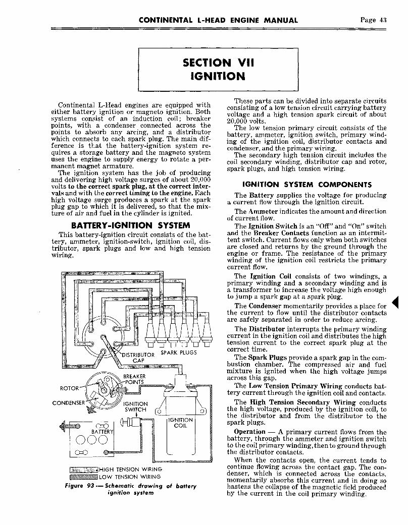
CONTINENTAL L-HEAD ENGINE MANUAL Page 43
SECTION VIIIGNITION
Continental L-Head engines are equipped witheither battery ignition or magneto ignition. Bothsystems con!dst of an induction coil; breakerpoints, with a condenser connected across thepoints to absorb any arcing, and a distributorwhich connects to each spark plug. The main dif-ference is t~at the battery-ignition system re-quires a storage battery and the magneto systemuses the engine to supply energy to rotate a per-manent magnet armature.
The ignition system has the job of producingand delivering high voltage surges of about 20,000volts to the correct spark plug, at the correct inter-vals and with the correct timing to the engine. Eachhigh voltage surge produces a spark at the sparkplug gap to which it is delivered, so that the mix-ture of air and fuel in the cylinder is ignited.
BATTERY-IGNITION SYSTEMThis battery-ignition circuit consists of the bat-
tery, ammeter, ignition-switch, ignition coil, dis-tributor, spark plugs and low and high tensionwiring.
CAP
SPARK PLUGS
CO IGNITIONSWITCH
,,~i~tHIGH TENSION WIRING~LOW TENSION WIRING
Figere 93---Schematic drawing of batteryignition system
These parts can be divided into separate circuitsconsisting of a low tension circuit carrying batteryvoltage and a high tension spark circuit of about20,000 volts.
The low tension primary circuit consists of thebattery, ammeter, ignition switch, primary wind-ing of the ignition coil, distributor contacts andcondenser, and the primary wiring.
The secondary high tension circuit includes thecoil secondary winding, distributor cap and rotor,spark plugs, and high tension wiring.
IGNITION SYSTEM COMPONENTSThe Battery supplies the voltage for producing
a current flow through the ignition circuit.The Ammeter indicates the amount and direction
of current flow.The Ignition Switch is an "Off" and "On" switch
and the Breaker Contacts function as an intermit-tent switch. Current flows only when both switchesare closed and returns by the ground through theengine or frame. The resistance of the primarywinding of the ignition coil restricts the primarycurrent flow.
The Ignition Coil consists of two windings, aprimary winding and a secondary winding and isa transformer to increase the voltage high enoughto jump a spark gap at a spark plug.
The Condenser momentarily provides a place forthe current to flow until the distributor contactsare safely separated in order to reduce arcing.
The Distributor interrupts the primary windingcurrent in the ignition coil and distributes the hightension current to the correct spark plug at thecorrect time.
The Spark Plugs provide a spark gap in the com-bustion chamber. The compressed air and fuelmixture is ignited when the high voltage jumpsacross this gap.
The Low Tension Primary Wiring conducts bat-tery current through the ignition coil and contacts.
The High Tension Secondary Wiring conductsthe high voltage, produced by the ignition coil, tothe distributor and from the distributor to thespark plugs.
Operation -- A primary current flows from thebattery, through the ammeter and ignition switchto the coil primary winding, then to ground throughthe distributor contacts.
When the contacts open, the current tends tocontinue flowing across the contact gap. The con-denser, which is connected across the contacts,momentarily absorbs this current and in doing sohastens the collapse of the magnetic field producedby the current in the coil primary winding.

Page 44 CONTINENTAL L-HEAD ENGINE MANUAL
This collapsing field induces a very high voltagein the secondary winding which is carried by thehigh tension wire to the center terminal of the dis-tributor cap. The rotor connects this center ter-minal to one of the cap terminals which in turn isconnected to the proper spark plug.
The spark produced by this high tension currentignites the fuel in that cylinder. This process isrepeated for every power stroke of the engine andat high speeds, an impulse may be required as oftenas 300 times per second.
Ignition Coil -- The function of the ignition coilis to transform the low voltage supplied by the bat-tery into the high voltage to jump the spark plugg~l’
SEALING
HIGH TENSION~TERMINAL
COIL CAP~.~
PRIMARY~
SEALING ~GASKETS
SECONDARYWINDING ~
PRIMARY~ ~ ~ Ill
:’o?’22E_
lAMINATION
PORCELAIN~ !INSULATOR
Figure 94--Cutaway View of an ignition coilAn ignition coil has two windings wound on a
soft iron core ; the primary winding which consistsof a comparatively few turns of heavy wire, andthe secondary winding of many thousand turns ofvery fine wire. The primary winding is woundaround the outside of the secondary winding. Asoft iron shell encloses the outside of both windingsand serves to complete the magnetic circuit.
Ignition coils do not normally require any serviceexcept keeping all terminals and connections cleanand tight. The coil should be kept reasonably clean ;however, it must not be subjected to steam cleaningor similar cleaning methods that may cause mois-ture to enter the coil.
Ignition coils can be tested for grounded wind-ings by placing one test point on a clean part of themetal container and touching the other point to theprimary and high voltage terminals. If tiny sparksappear at the points of contact, the windings aregrounded.
If the coil is further suspected of being faulty,remove and check its operation on a coil tester andreplace it if inoperative. Most coil testers comparethe operation of the coil being tested with oneknown to be in good condition. This test should bemade with the coils at room temperature and then
warming the coils five minutes by connecting theprimary to a battery of the same voltage rating asthe coils. Recheck the comparison test to see if theexpansion due to heating has caused some defectto appear.
Distributor -- The distributor conducts and in-terrupts the current through the primary windingof the ignition coil at the correct time and distrib-utes the high tension voltage to the correct sparkplug.
There are two separate electrical circuits in adistributor. The breaker contacts and condenserare in the primary circuit and carry low voltagecurrent -- while the cap and rotor are in the sec-ondary circuit and carry the high voltage sparkcurrent.
ROTOR ~
CONDENSER~
.........’ HOL~R~OWN
DRIVESHAFT
Figure 95--Cutaway View of a distributor
The breaker contacts are mounted on a plate inthe top part of the distributor housing. Thegrounded contact is stationary and the insulatedcontact is mounted on a breaker arm which is ac-tuated by a cam near the top of the distributorshaft.
The rotor is mounted above the cam and turnswith it to make a connection between the cap centercontact and the various side contacts.
Continental L-Head engines have distributorsequipped with a centrifugal governor which variesthe timing by advancing the breaker cam as theengine speed increases. This mechanism consists ofweighted levers which revolve with the distributorrotor and act against a set of springs. As the speedof rotation increases, the weights are moved outand the timing is advanced. With this arrangementit is possible to have a retarded spark for idling andobtain a gradual advance in spark timing as theengine speed is increased.

CONTINENTAL L-HEAD ENGINE MANUAL Page 45
The condenser in the distributor prevents exces-sive arcing at the contacts. When the contacts firstopen, the current tends to continue flowing acrossthe gap. The c.ondensor absorbs tliis current untilit becomes fully charged ; but by this time, the con-tacts have opened far enough to prevent the cur-rent flow. If there were no condenser in the circuit,the current wc.uld continue to flow arid cause an arcthat would soon burn the contacts. The capacity ofthe condenser is designed to be large enough to pre-vent arcing and burning of the contacts and smallenough to reduce the transfer of material from onecontact to the other.
The cam is designed so that the breaker pointsremain closed for a certain number of degrees soas to give the coil a given length of time to buildup or become energized. This is called the camangle, as shown below :
CAM \,
Figure 96---Diagram illustrating cam angle
The cam is further designed to open the breakerpoints at a giw~n speed in relation to cam travel toobtain proper poin~ and condensor action. It istherefore important that the breaker points be ad-justed to .020 gap so that proper cam angle isobtained.
DISTRIBUTOR MAINTENANCE -- The distribu-for operation is vital to the operation of the engineand the following items should be carefully in-spected every 250 hours of normal operation ; how-ever, dirt, dusL water and high speed operationmay cause more rapid wear and necessitate morefrequent inspections :
1--Remove Distributor Cap- (without re-moving wires) -- Clean cap and examine forcracks, carbon runners, corroded terminals or ifthe vertical faces of the insexts are burned --install a new cap.
If the horizontal faces of the inserts areburned -- replace the cap and rotor as this is dueto the rotor being too short.
2- Check Centrifugal Advance Mechanism --for "freeness" by turning the breaker cam in thedirection of rotation and then releasing it. Theadvance springs should return the cam to itsoriginal position.
3 -- Inspect Breaker Points and Gap -- if pointsare pitted, burned or worn to an unserviceablecondition, install a new set of points. Badly pittedpoints may be caused by a defective or impropercondenser capacity.
If the condenser capacity is too high, thecrater (depression) will form in the positive con-tact ; and, i/ condenser is too low, the crater willform in the negative contact as shown on- thefollowing sketch.
CONTACT BRACKET
BREAKER ARM
OVER CAPACITYCONDENSER
CONTACT BRACKET
UNDER CAPACITYCONDENSER
Figure 97 ~ Badly pitted breaker points causedby arcing due to incorrect condensor capacity

Page 46 CONTINENTAL L-HEAD ENGINE MANUAL
If the points are servicable, they should bedressed down with a fine-cut stone or point file.The file must be clean and sharp -- never useemery cloth to clean contact points.
After filing, check the point gap and reset to.020 -- the breaker arm must be resting on thehigh point of the cam during this operation.
When replacing points, make sure they arealigned and that they make full contact. Bend thestationary arm to obtain proper alignment -- donot bend the breaker arm.
4 -- Lubrication -- is required at the shaft, ad-vance mechanism, breaker cam and pivot. Theshaft may be either oil or grease cup lubricatedand should be given attention every oil change.Make sure the breaker arm moves freely on itshinge and apply a drop of light oil. A trace ofball bearing lubricant such as Mobilgrease Spe-cial (with Moly) should be used sparingly on thebreaker cam unless lubricated by a felt wick witha few drops of oil.
CAUTION:AVOID EXCESSIVE LUBRICATION -- ASTHE EXCESS MAY GET ON THE CONTACTPOINTS AND CAUSE BURNING.
SPARK PLUGS -- A spark plug consists of twoelectrodes; one grounded to the outer shell of theplug and the other well insulated with a core ofporcelain or other heat resistant material. Thespace between these two electrodes is called the gapwhich should be set at .025 on standard plugs, and.035 on resistor type plugs for Continental L-HeadEngines. Correct and uniformity of the gaps of allspark plugs in the engine is important for smoothrunning.
GAP--
CERAMIC INSULATOR
~ -SEALS
LECTRODES
Figure 98 ~ Sectional view of spark plug
Spark plug gaps are best checked with a wiregauge unless the points are dressed to obtain a cor-rect reading with a flat gauge. The adjustmentshould always be made on the side electrode and
never on the center electrode which may cause abroken porcelain.
"Gapping" the electrode tip is more easily donewith proper tools.
GAPPING THE SPARK PLUG. This illustrationshows the use of the gapping tool which bothmeasures and adjusts the electrode gap.
Figure 9Om Checking spark gap
Spark Plugs must operate within a certain tem-perature range to give good performance -- not toohot and not too cold. The abidty of a spark plugto conduct heat away from the center electrodeand porcelain is controlled by the design of theshell and insulator -- so varying the length of theinsulator below the gasket shoulder controls thetemperature.
COLDPLUG
HEAT AWAYFROM OORE HEAT AWAY
FROM CORESLOWLY
Figure 100 ~ Cold ~ Normal ~ Hot Spark Plugs
Cold-Normal-Hot Spark PlugsExamination of a used spark plug will show if it
is in the correct heat range for the operating con-ditions. If the plug runs too hot, the insulator willblister or crack and the electrodes burn awayrapidly. If the plug remains too cool -- soot andcarbon will deposit on the insulator causing foulingand missing.

CONTINENTAL L-HEAD ENGINE MANUAL Page 47
Figure 101 ~ Faulty spark plugs. Left: cold plug usedin an engine that should have a hot plug. Right: hotplug used in ar~ engine that should have a cold plug.
Spark plug electrodes will wear in the course oftime and present day fuels have a tendency to formrusty-brown oxide deposits on the insulator tip.Therefore it is necessary to periodically clean theplugs with & plug cleaner and to reset the gaps tospecifications.
Sp&rk plugs must be correctly installed in orderto obtain good performance from them. It is asimple but important matter to follow the followingprocedure when installing plugs:
1. Clean the spark plug seat in the cylinder head.
2. Use new seat gasket and screw plug in byhand.
3. Tighten all 18mm plugs to 35¢~ torque withsocket wrench of correct size.
DISTRIBUTOR -- IGNITION TIMINGWith Timing Light
C_.RANK, SHAFT PULLEYMETHOD
FLYWHEEL k~lE THOD
BLUE~ I
RED
Figure 102-- Schematic diagram sho~vingtiming light hookup
Normally Continental L-Head engines with dis-tributor-ignition are timed to have the distributorpoints start to open when ¢~1 cylinder is on com-pression stroke and the flywheel mark "DC" (top-dead-center) lines up with the pointer in the bellhousing.
There are two methods of checking ignition tim-ing -- with or without a timing light.
The preferred method is to use a timing light infollowing sequence:
Paint a line on the flywheel (or in some cases,on the front pulley) so the timing mark will bemore legible under the timing light.
1. Clip blue secondary lead of light to thespark plug -- leave spark plug wire on plug.
2. Connect primary positive lead (red) to posi-tive terminal of battery.
3. Connect primary negative lead (black) negative battery terminal.

Page 48 CONTINENTAL L-HEAD ENGINE MANUAL
Figure 103 reChecking flywheel timing withtiming light
4. Start engine and run at idle speed, 400 RPMor lower, so the automatic advance of the distribu-tor is completely retarded. THIS IS VERY IM-PORTANT TO OBTAIN CORRECT TIMING.
5. Direct timing light on the crankshaft pulleyor on the flywheel through opening in bell housingand note timing marks as light flashes.
6. Timing is normally at "D.C." unless specifiedotherwise on your engine specification sheet.
7. To advance timing, turn distributor bodyclockwise. To retard timing, turn distributor bodycou nter-clockwise.
8. When timing is correct, tighten distributorclamp screw securely. Then recheck timing againwith light.
9. This operation is best performed in shadedarea, so timing light is visible.
DISTRIBUTOR IGNITION TIMING
Without Timing Light(Emergency Method)
An alternative method without timing light, isas follows :
1. Remove ¢~1 Spark Plug -- put your thumbover the spark plug hole and crank engine byhand until air is exhausting.
2. Set piston on top-dead-center by slowly crank-ing until "DC" mark on flywheel (or crank~shaft pulley) will line up with the pointer inbell housing (or gear cover).
Note: Some special applications may be timedseveral degrees before top dead center (BTDC).
Figure 104 D Checking No. I Cylinder onCompression Stroke
Figure I04A ~ Flywheel timing marks
Figure 104BDCrank pulley timing mark
3. Loosen the distributor clamp bolt and rotatethe distributor body until the contact points justStart to Open.This may be more accurately checked by means
of a test lamp connected between the distributorprimary lead and the negative terminal of the bat-tery -- when the points are closed the light will beON and as soon as the points break the light willgo OFF.

CONTINENTAL L-HEAD ENGINE MANUAL Page 49
4. Tighten distributor mounting bolts.
In high altitt..des there is less tendency for sparkping as well as low altitudes with premium gas-olines. In suclh cases, improved performance maybe obtained by s:dvancing the spark not to exceed4 degrees ahe~td of specified setting.
CAUTION: WHEN ENGINE SPECIFICA-TIONS HAVE SPECIAL TIMING OTHERTHAN TOP-DEAD- CENTER- THEYMUST BE FOLLOWED IN ORDER TOOBTAIN SATISFACTORY SERVICE INSPECIAL APPLICATIONS OR HIGHERALTITUDES.
MAGNETO - IGNITIONMagneto-Ignition is furnished on Continental
L-Head engines on special applications to providea complete ignition system without requiring a bat-tery. The smaller engines are easily hand-crankedso that the starters and generators are not fur-nished in many of these applications.
The magneto comprises all the parts of the bat-tery-ignition system with the exception of the
battery, and in addition, means for. generating cur-rent impulses directly in the primary winding--which is in effect a spark coil.
The advantage of the magneto is this self-con-tained character. All the elements of the ignitionsystem are in one compact unit, from which it onlyrequires a low-tension cable to the ignition switchand high-tension cables to the spark plugs.
Figure 104C--Magneto installation
OperationMagnetos are of the rotating magnet type with
jump-spark distributor and are flange mounted toan accessory timing gear drive.
The rotation of the magnetic rotor sets up analternating magnetic flux which cuts the primarywinding each time it rises and falls. This induceselectric curre.nts, alternating in direction, to flowin the primary circuit during the intervals thebreaker points are closed.
The current in the primary winding of the coilestablishes a magnetic field which interlocks theturns of the coil secondary winding, this field reach-ing its maximum simultaneously with the primarycurrent. Breaker point action at the instant ofmaximum primary current and field, opens theprimary circuit so the primary current can’t flow-- causing the immediate and complete collapse ofthe magnetic field existing in the coil.
Schematic drawing of magneto ignitionCOIL ~
~ ~ ......................
Figure 105

Page 50 CONTINENTAL L-HEAD ENGINE MANUAL
The ratio of turns in the coil secondary windingto those of the primary is very high so the inducedvoltage in the secondary winding is also very high.
The self-induced voltage occurring in the pri-mary winding, as a result of the quick break of the
primary circuit, is absorbed by the condenser whichis shunted across the breaker points. This actionpromotes a more rapid collapse of the primary fieldand at the same time reduces contact point burn-ing caused by arcing.
IMPULSE COUPLING
All magnetos have an impulse coupling whichassists starting by automatically retarding theignition spark during the starting operation andat the same time producing an intense, hot spark-- which would otherwise be impossible at verylow engine speeds.
This device prevents the rotor of the magnetofrom turning during the starting operation untilthe engine piston is about at top-dead-center, atwhich instant the rotor is snapped forward at veryhigh speed, producing an intense spark which is
automatically retarded to prevent back~firing.Since the point at which the release occurs can becontrolled in the coupling construction -- it is pos-sible to provide an automatic retard of the ignitionspark during the starting period.
Basically the impulse coupling consists of ashell and a hub, connected together by a strongspring. One half of the coupling (shell) is fitted a drive member on the engine drive shaft -- whilethe other half (hub) is keyed to the magneto ~otorshaft.
STARTING SPEEDS
PAWL rOBREAKER ChM
LINKAGE
PAWL SPRING/’~ONTRC}I S SPARK
A(~VANCE RELATIONTO ROTATIV E
SPEED
PAWL STOPL I M I’f S
AMCUNT OFSPARK
.&DVANC[WH E f;
NECESSARY
RUNNING SPFFOS
Figure 106 ~ Operation of Automatic SparkAdvance Rotor
AUTOMATIC SPARK ADVANCE
In slow speed operation, a pawl on the magnetohalf of the coupling engages a stop pin mountedon the magneto frame -- which prevents furthermovement of the rotor. The engine half of thecoupling continues to rotate and the relative changein position winds up the connecting spring.
When the desired point of ignition spark is
reached, the pawl is released and the drive springsnaps the magneto rotor forward at high speedthrough its firing position.
As the engine speed increases, the centrifugalforce acting on the pawls -- withdraws them to aposition not engaging the coupling stop pin -- theimpulse coupling then acts as a solid drive member.

CONTINENTAL L-HEAD ENGINE MANUAL Page 51
TIMING MAGNETO TO ENGINE
1. Remov~ rear spark plug (#4 on four cylinder and#6 on six cylinder engines.)
2. Set piston on top-dead-center by slowly crankinguntil "DC" mark on flywheel (or crankshaft pulley)will line up with the pointer in the flywheel housing(or gear cover).
3. With magneto removed from the engine -- put itfirmly in a vise lined with soft cloths and turn drive lugsof impulse coupling until lead to rear plug (#4 or #6)fires.
Bosch and Wi,:o magneto indicate # 1 lead so rear plugis directly opposite -- F. M. magnetos are not marked,but rear plug lead is at 5 o’clock position when facingdistributor end.
tl. Check front end governor drive and make certainthat punch-marked tooth of timing gear is meshing be-tween the two punch-marked teeth of the governor drivegear.
5. Turn back magneto drive lugs of impulse couplingcounter-clockwise about 1/~ turn so as to mesh with thedriving slots of the engine drive member.
6. Position magneto on engine and tighten mountingbolts moderately and connect wires to spark plugs.
7. Start and idle engine 600 R.P.M. and using atiming light connected to rear plug and battery source--check to see; if timing is directly at "IGN-M" indi-cated by pointer.
If not, rotate magneto assembly until timing is correct,then tighten magneto mounting bolts.
IMPORTANT: Engine specifications require magnetos with the correct amount of "Built-in Lag" --which permits timing the magneto to the engine correctly as outlined.
Do not substitute other magnetos.
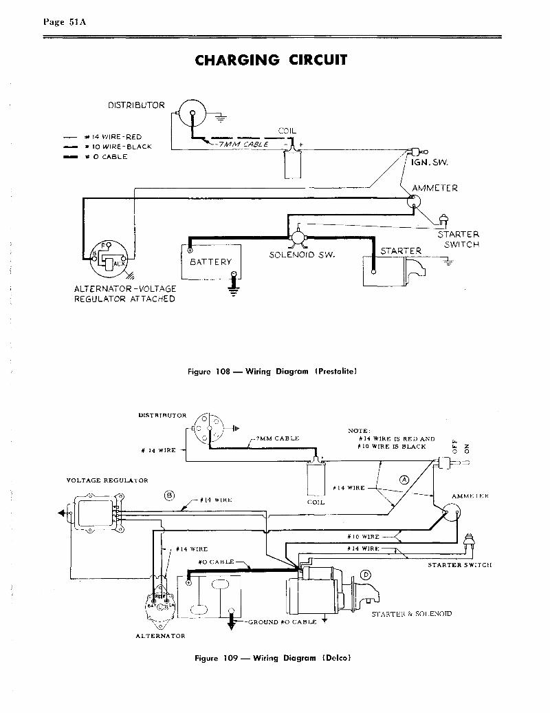
Page 51A
CHARGING CIRCUIT
DISTRIBUTOR
14-WIRE-RED
IO WIRE- BLACK
O CABLE
ALTERNATOR -VOLTAGEREGULATOR ATTACHED
C~L£
60LEMOID SVv’.
START E P,SWITCH
Figure 108--Wiring Diagram (Prestolite)
DISTRIBUTOR
# 14 WIRE ~
-7MM CABLENOTE:
#14 WIRE IS RED AND#10 WIRE IS BLACK
0 0
VOLTAGE REGULATOR
-- # 14 WIRE COIL
~~ARTER ~ SOLENOID
ALTERNATOR
Figure 109--Wiring Diagram (Delco)

The charging circuit consists primarily of a gen-erator, regulator, battery and wiring. When ana-lyzing the charging circuit, the components shouldbe checked in the following order:
I. Wiring
Wiring in the charging circuit should be care-fully inspected for frayed insulation or otherdamage, an.d replace any wiring that is defec-tive. Also inspect all connections to the gen-erator, re~:ulator and battery (including allground connections), and clean and tightenas required.
II. Battery
The lead-acid .storage battery, used on auto-motive and industrial applications, is an elec-trochemical device for converting chemicalenergy into electrical energy.
It has three major functions:
1. It provides a source of curren.t for start-ing tl~e engine.
2. It acts as a stabilizer to the voltage inthe electrical system.
3. It car~, for a limited time, furnish cur-rent when the electrical demands of theunit exceed the output of the generator.
There are ~wo types of batteries with whichwe are concerned: The DRY charged and theWET charged.
The DRY charged is shipped from the fac-tory with charged plates, and the electrolyteis added wlhen the battery is ready to be ac-tivated.
The WET charged battery is shipped fromthe factory with the electrolyte already added.This type must be recharged periodically,while in storage, to keep it ready for service.
Battery Testing
Visual Test -- The battery should be in-s, pected visually, checking the level of theelectrolyte and the outside of the battery fordamage and abuse.
Page 51B
The
1.
"In-Vehicle" Light Load Test
First, if the electrolyte level is low, ad~just it to the proper level by addingwater.
Then place a load in the battery by hold-ing the starter switch "ON" for threeseconds, or until the engine starts. Ifthe engine starts, turn off ignition im-mediately. This removes the surfacecharge.
Then, turn the headlights on low-beam.The headlights must be turned on forone minute before starting the light loadtest and then left on during the test.
If any cell reads 1.95 volts or more andthe diff.erence between the highest andlowest is less than .05 volt, the batteryis good.
The "Out-of-Vehicle" Light Load Test
This test is conducted in the same way asthe "In-Vehicle" test.
To check the electrical condition of batterycells :
Place a 150 ampere load on battery forthree seconds, using a high rate loadtester, to remove surface charge.
Then, place a ten ampere load on batteryfor one minute before starting the LightLoad Test. The difference in voltagereadings between the individual cells canbe interpreted in the same way as indi-cared under the "In-Vehicle" Light LoadTest.
Specific Gravity Cell Comparison Test
This test should be used only on batterieshaving one-piece cell covers. Measure thespecific gravity of each cell, regardless ofstate of charge, and interpret results as fol-lows :
If the maximum difference between cellreadings is les.s than .050 (50 points) andthe lowest cell reading is 1.200 or above,the battery is good.
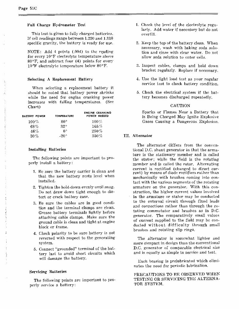
Page 51C
Full Charge Hydrometer Test
This test .is given to fully charged batteries.If cell readings range between 1.230 and 1.310specific gravity, the battery is ready for u~e.
NOTE: Add 4 points (.004) to the re.adingfor every 10°F electrolyte temperature above80°F, and subtract four (4) points for every10~F electrolyte temperature below 80°F.
Selecting A Replacement Battery
When selecting a replacement battery itshould be noted that battery power shrinkswhile the need for engine cranking powerincreasesChart)
with falling temperatures. (See
ENGINE CRANKINGBATTERY POWER TEMPERATURE POWER NEEDED
100 % 80 o 100 ~68 % 32 o 165 %46% 0° 250%30% -20° 350%
Installing Batteries
The following points are important to pro-perly install a battery:
1. Be sure the battery carrier is clean andthat the new battery rests level wheninstalled..
2. Tighten the hold-down evenly until snug.Do not draw down tight enough to dis-tort or crack battery case.
3. Be .sure the cables are in good condi-tion and the terminal clamps are clean.Grease battery terminals lightly beforeattaching cable clamps. Make sure theground cable is clean and tight at engineblock or frame.
4. Check polarity to be sure battery is notreversed with respect to the generatingsy,stem.
5. Connect "grounded" terminal of the bat-tery last to avoid short circuits whichwill damage the battery.
Servicing Batteries
The following points are important to pro-perly service a battery:
o
Check the level of the electrolyte regu-larly. Add water if necessary but do notoverfill.
Keep the top of the battery clean. Whennecessary, wash with baking soda solu-tion and r.inse with clear water. Do notallow soda solution to enter cells.
Inspect cables, clamps and hold downbracket regularly. Replace if necessary.
Use the light load test as your regularservice test to check battery condition.
Check the electrical system if the bat-tery becomes discharged repeatedly.
CAUTION
Sparks or Flames Near a Battery thatis Being Charged May Ignite ExplosiveGases Causing a Dangerous Explosion.
III. Alternator
The alternator differs from the conven-tional D.C. shunt generator in that the arma-ture is the stationary member and is calledthe stator; while the field is the rotatingmember and is called the rotor. Alternatingcurrent is rectified (changed to direct cur-rent) by means of diode rectifiers rather thanmechanically with brushes coming into con-tact with the various segments of the rotatingarmature on the generator. With this con-struction, the higher current values involvedin the armature or stator may be conductedto the external circuit through fixed leadsand connections rather than through the ro-tating commutator and brushes as in D.C.generator. The comparatively small valuesof current supplied to the field may be con-ducted without difficulty through smallbrushes and rotating slip rings.
The alternator is somewhat lighter andmore cbmpact in design than the conventionalD.C. generator of comparable electrical sizeand is equally as simple to service and test.
Each bearing is prelubricated which elimi-nates the need for periodic lubrication.
PRECAUTIONS TO BE OBSERVED WHENTESTING OR SERVICING THE ALTERNA-TOR SYSTEM.

Pa~e 51D
1. DI~,CONNECT THE BATTERY, beforeconnecting or disconnecting test instru-ments (except voltmeter) or before re-mo~Ting or replacing any unit or wiring.Accidental grounding or shorting at thereg:alator, alternator, ammeter or acces-sories, will cause severe damage to theunil:s an.d/or wiring.
2. TO AVOID DAMAGE TO THE REGU-LATOR, DO NOT, AT ANY TIME,CONNECT BATTERY TO THE REG-ULATOR FIELD TERMINAL.
3. THE FIELD CIRCUIT MUST NEVERBE GROUNDED, ON THIS SYSTEM,BETWEEN THE ALTERNATOR ANDTHE REGULATOR. Grounding of thefield terminal either at the alternator orregulator will damage the regulator.
4. IF IT IS NECESSARY TO SOLDERANY LEAD TO A RECTIFIER LEAD,use a pair of pliers as a heat dam be-tween the solder joint and the rectifier.
5. THE ALTERNATOR MUST NOT BEOPERATED ON OPEN CIRCUIT WITHTHE ROTOR WINDING ENERGIZED.
6. DO NOT ATTEMPT TO POLARIZETHE ALTERNATOR. No polarizationis required. Any attempt to do so mayresc~lt in damage to the alternator, reg-lator, or circuits.
7. GROUNDING OF THE ALTERNATOROU~?PUT TERMINAL MAY DAMAGETHE ALTERNATOR AND/OR CIR-CUIT AND COMPONENTS.
8. REVERSED BATTERY CONNEC-TIONS MAY DAMAGE THE RECTIFI-ERS, WIRING OR OTHER COMPON-ENTS OF THE CHARGING SYSTEM.Battery polarity should be checked witha voltmeter before connecting the bat-tery.
9. IF A BOOSTER BATTERY OR FASTCHARGER IS USED, ITS POLARITYMUST BE CONNECTED CORRECTLYTO PREVENT DAMAGE TO THEELECTRICAL SYSTEM COMPON-ENTS. (POSITIVE TO POSITIVE,NEGATIVE TO NEGATIVE).
IV. Regulator
Some regulators are fully transistorizedand completely .sealed. These can not be ad-justed or repaired, and it can be assumedthat this type regulator will outlive the othercomponents in the charging system.
Other regulators are adjusted and repairedin accordance with the manufacturer’s in-structions.
Installation of Regulator for Alternator
To insure proper operation and to protectthe alternator and regulator, the followingsteps should be observed during installation.
1. Make sure regulator is of the same volt-age and polarity as the alternator andbattery.
2. Disconnect battery cable at battery ter-minal.
Make sure the mounting area of the al-ternator and regulator base are cleanand make a good tight connection.
Connect alternator in accordance withthe manufacturer’s instructions.
5. Do not flash field or ground terminalsof the regulator.
Reconnect battery cable.
Start engine and observe ammeter. A"High" charge rate is normal for thefirst few minutes, but will decrease asthe regulator warms up.
NOTE : When servicing the charging system, nev-er remove a unit until tests have shownit to be defective. Reference alwaysshould be made to the manufacturer’smaintenance manuals for a completetrouble shooting story.

Page 52 CONTINENTAL L-HEAD ENGINE MANUAL
SECTION VIIIENGINE REPAIR AND
OVERHAUL
This section includes instructions for repairs andoverhaul of the component units of ContinentalRed Seal L-Head engines.
Provide a clean place to work and clean the en-gine exterior before you start disassembling --dirt causes engine failures. Many shop tools havebeen developed to save time and assure good work-manship; these should be included in your equip-ment.
Use only genuine Red Seal parts in Continentalengines since years of development and testinghave gone into these specifications to assure max-imum life and performance.
CYLINDER HEADThe cylinder head is an important part of the
engine assembly since it contains the complete com-bustion chamber and cored passage for water flow.Remove the cylinder head in the followingsequence:
1. Drain water from engine and disconnect rad-iator or heat exchanger outlet hose.
2. Loosen and remove the nuts holding the cylin-der head to the block.
3. Lift the cylinder head off the engine and carryto a clean bench for further disassembly.
4. Remove all carbon from combustion areasusing a scraper and wire brush.
5. Clean the cylinder head thoroughly with asolvent or degreasing solution and blow it offwith air pressure.
6. Make sure that gasket contact surfaces onthe head and block are clean, smooth and flat.
Figure 11 1 m Checking cylinder head flatnesslengthwise.
7. Check out-of-flatness with straight edge andfeeler gauge: maximum permissible is .00075inches per inch of width or length. Thus, for acylinder head 16" long, maximum permissiblelengthwise out-of-flatness is .012". Out-of-flat-ness should vary gradually and uniformly fromend to end and side to side. Localized depres-sions or high spots should not exceed .003.
Figure 110 ~ Cleaning carbon fromcombustion chamber
Figure 112 m Checking cylinder head flatnesscrosswise.

CONTINENTAL L-HEAD ENGINE MANUAL Page 53
CYLINDER BLOCK
Figure 1 13 ~ Valve Removal
1. With a valve spring lifter, compress thesprings and remove the locks or pins from the valvestems which are in a closed position. Close theother valves by rotating the crankshaft and re-move the locks (or pins) from these valves in thesame manner. Remove all valves and place in orderin a rack, with holes numbered for both intake andexhaust valve:~ so they will not be mixed inhandling.
Figure 114 N Valves in rack
VALVE GUIDES
1. Clean the valve stem guides, removing lacqueror other deposits by running a valve guide cleaneror wire brush through the guides.
2. Check guides for wear by using "Go and No-Go" plug gage or a. telescope gage and 1" microm-eter. Replace all guides that are worn bell-mouthedand have increased .0015 in diameter. See Limitsand Clearance Section fol; maximum diameter per-missible to determine actual amount the diameterhas increased. Remove all valve gtfides when neces-sary by using an arbor press and pressing them outfrom the combustion chamber side with a driverslightly smaller than the O.D. of the valve guide.
Figure 115 ~ Removing valve guides
3. Replace worn guides as required by using asuitable driver and an arbor press from the combus-tion side to the correct depth below the valve seatas given in the Limits and Clearance Chart.

Page 54 CONTINENTAL L-HEAD ENGINE MANUAL
I ~ INTAKE
_
VALVE SEAT INSERTS
1. The exhaust valve seat insert is held in placeby a shrink fit.
Inspect all exhaust valve inserts in the block andreplace any that are loose, cracked or otherwisedamaged. Use puller for removing faulty insert asshown in illustration.
EngineDistance from Block Face to
Top of Guide
Intake Exhaust
N56, N62 2%2 2%2
Y69, Y91, Yl12 7/8 7/8
F-4 F-6
~eries
M271, M290M330, M363 11~ 19/16
B371, B427 17/8
Figure 116 m Diagram and chart showingvalve guide location
CAUTION: When replacing guides that areferrox coated do not ream since these are allpre-reamed before being ferrox coated m anyfurther reaming will remove the coating.
Figure 117 ~ Removing exhaust valve seat insert
2. When required to replace with new insert,clean and counterbore for .010 larger insert usingcounterbore tool with correct fitting pilot.
When machining the counterbore, be sure to godeep enough with the tool to clean up the bottom sothat the insert will have full contact to carry awaythe heat.
Continental does not recommend installing newinserts having the same outside diameter as theone removed. The following chart shows the dimen-sions of Standard Inserts and counterbores :
DIMENSIONS OF STANDARD INSERTSAND COUNTERBORES
Outside Dia. Inside Dia.Engine Model of Inse~:t of Counterbore Press Fit
(A) (B)
N-56 1.068-1.067 1.063-1.062 .004-.006N-62Y-69Y-91 1.1295-1.1285 1.1258-1.1245 .003-.005Y-112
F124 F135F140 F163F244 F245 1.3485-1.3475 1.3445-1.3435 .003-.005
F162F-186 F-209
F-226 1.442-1.441 1.438-1.437 .003-.005F-227M-271M-290 1.692-1.691 1.688-1.687 .003-.005M-330M-363B-371B-427 1.8785-1.8775 1.8755-1.8745 .003-.005

CONTINENTAL L-HEAD ENGINE MANUAL Page 55
Figure 117-A m Insert and counterbore
When OVERSIZE inserts are used, dimensionsof the insert and counterbore increase proportion-ately (.010, .020 -- depending on the oversize).
New insert installation should have a press fit.Chill insert in container with dry ice for 20 min-utes before as,~;embling.
Insert may then be installed in the counterboreusing a piloted driver, tapping in place with verylight hammer blows, without the possibility ofshearing the side walls. This assures it being seatedfirmly on the bottom of the counterbore.
3. Grind the intake and exhaust valve seats inthe block in accordance with instructions in thelimits and clearance chart and before removing thearbor, indicate the seat. Total indicator readingof the run-out must not be more than .002". Use apilot having a solid stem with a long taper, as allvalve seats must be ground concentric and squarewith either new or worn valve stem guide holes.
Figure 119 ~ Grinding Valve Seat
Figure 118 ~ Installing valve seat insertwith an arbor press
Figure 120 ~ Indicating Valve Seat
VALVES
1. Inspect valves for condition and replace anythat are "necked", cracked or burned, also any on
which valve stems are bent or worn more than .002over the maximum allowable limits. Reface or re-place all valves.
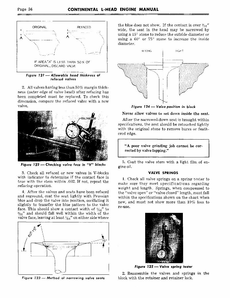
Page 56 CONTINENTAL L-HEAD ENGINE MANUAL
ORIGINAL REFACED
IF AREA UA" IS LESS THAN 50 % OFORIGINAL, DISCARD VALVE
Figure 121 ~ Allowable head thickness ofrefaced valves
2. All valves having less than 50% margin thick-ness (outer edge of valve head) after refacing hasbeen completed must be replaced. To check thisdimension, compare the refaced valve with a newvalve.
the blue does not show. If the contact is over ~5_0"wide, the seat in the head may be narrowed byusing a 15° stone to reduce the outside diameter orusing a 60° or 75° stone to increase the insidediameter.
WRONG RIGHT
Figure 124 -- Valve position in block
Never allow valves to set down inside the seat.
After the narrowed-down seat is brought withinspecifications, the seat should be retouched lightlywith the original stone to remove burrs or feath-ered edge.
"A poor valve grinding job cannot be cor-rected by valve lapping."
Figure 122 ~ Checking valve face in "V" blocks
3. Check all refaced or new valves in V-blockswith indicator to determine if the contact face istrue with the stem within .002. If not, repeat therefacing operation.
4. After the valves and seats have been refacedand reground, coat the seat lightly with Prussianblue and drop the valve into position, oscillating itslightly to transfer the blue pattern to the valveface. This should show a contact width of V16" to~2" and should fall well within the width of thevalve face, leaving at least 1~4" on either side where
Figure 123--Method of narrowing valve seats
5. Coat the valve stem with a light film of en-gine oil.
VALVE SPRINGS
1. Check all valve springs on a sprin~ tosser tomake sure they meet specifications regardingweight and length. Springs, when compressed tothe "valve open" or "valve closed" length, must fallwithin the specifications shown on the chart whennew, and must not show more than 10% loss tore-use.
Figure 125 ~ Valve spring tester
2. Reassemble the valves and springs in theblock with the retainer and retainer lock.

CONTINENTAL L-HEAD ENGINE MANUAL Page 57
CHECKING BORE WEAR
1. Clean the ring of carbon from around the topof the cylinder bore formed above the travel ofthe top ring.
2. Determine the original diameter of the cylin-der barrel by checking this unworn area with apair of inside micrometers at intervals of ap-proximately 45°.
PREPARING CYLINDER WALL5 FOR RE-RINGINGOR REBORING
1. Ridge ream the cylinders to remove the un-worn area at the top so that the new rings whenassembled will not bump and distort both them-selves and the piston lands.
Figure 127 ~ Ridge reaming top of cylinder bore
Figure 126 m. Measuring original bore diameterabove ring travel
3. Check in same manner the top of the ringtravel area approximately 1~,, below theshoulder.
4. The maximum difference in the above checks,indicates the amount of cylinder bore wear. Ifless than .008, re-ringing will be suitable and ifover .008 re-boring is recommended.
Several good makes of ridge reamers are avail-able which will ream the top of the bore in directrelation to the worn area so that should the wornarea be off center slightly there will be no partialridge remaining.
2. Drain the crankcase and remove the oil pan.
3. Remove the cap screws holding the connect-ing rod caps to the rod. Keep the cap and boltsin numerical order so that when the pistons androds are removed from t~e engine, the cap canbe reassembled and kept with its mating part.
4. Push the pistons and connecting rods upthrough the top of the cylinder, carrying withthem all the carbon and metal chips left fromthe cleaning and ridge reaming operation. Whendoing this. c~’c’r~l precc~ution must bc taken toprc~’ent da~?~cUle ~o cylinder bores by the st~arpcorners and ?’o~gt~ ~’dgcx of the connecting rod,~and bolts.
5. To get the correct cross hatch pattern witha cylinder hone, use a top quality electric drillwith a speed of 500 RPM or less.
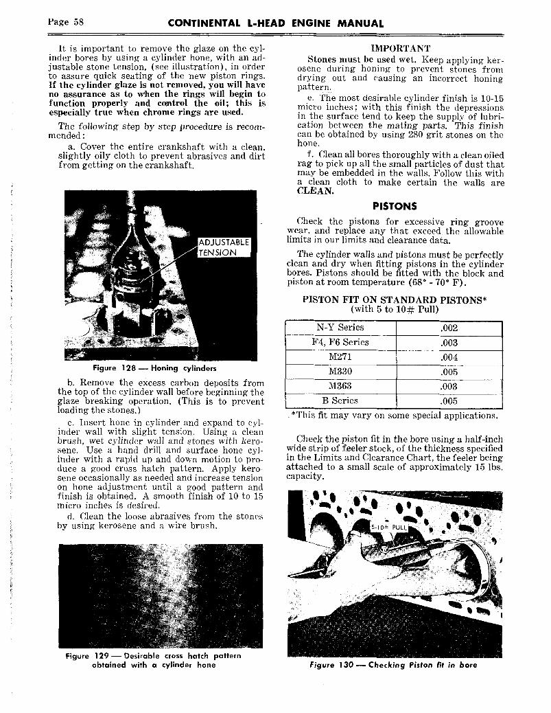
Page 58 CONTINENTAL L-HEAD ENGINE MANUAL
It is important to remove the glaze on the cyl-inder bores by using a cylinder hone, with an ad-justable stone tension, (see illustration), in orderto assure quick seating of the new piston rings.If the cylinder glaze is not removed, you will haveno assurance as to vchen the rings will begin tofunction properly and control the oil; this isespecially true when chrome rings are used.
The following step by step procedure is recom-mended :
a. Cover the entire crankshaft with a clean,slightly oily cloth to prevent abrasives and dirtfrom getting on the crankshaft.
Figure 128mHoning cylinders
b. Remove the excess carbon deposits fromthe top of the cylinder wall before beginning theglaze breaking operation. (This is to preventloading the stones.)
c. Insert hone in cylinder and expand to cyl-inder wall with slight tension. Using a cleanbrush, wet cylinder wall and stones with kero-sene. Use a hand drill and surface hone cyl-inder with a rapid up and down motion to pro-duee a good cross hatch pattern. Apply kero-sene occasionally as needed and increase tensionon hone adjustment until a good pattern andfinish is obtained. A smooth finish of 10 to 15micro inches is desired.
d. Clean the loose abrasives from the stonesby using kerosene and a wire brush.
IMPORTANTStones must be used wet. Keep applying ker-
osene during honing to prevent stones fromdrying out and causing an incorrect honingpattern.
e. The most desirable cylinder finish is 10-15micro inches; with this finish the depressionsin the surface tend to keep the supply of lubri-cation between the mating parts. This finishcan be obtained by using 280 grit stones on thehone.
f. Clean all bores thoroughly with a clean oiledrag to pick up all the small particles of dust thatmay be embedded in the walls. Follow this witha clean cloth to make certain the walls areCLEAN.
PISTONS
Check the pistons for excessive ring groovewear. and replace any that exceed the allowablelimits in our limits and clearance data.
The cylinder walls and pistons must be perfectlyclean and dry when fitting pistons in the cylinderbores. Pistons should be fitted with the block andpiston at room temperature (68° - 70° F).
PISTON FIT ON STANDARD PISTONS*(with 5 to 10~: Pull)
N-Y Series .002
F4, F6 Series .003
M271 .004
M330 .005
M363 .003
B Series .005
*This fit may vary on some special applications.
Check the piston fit in the bore using a half-inchwide strip of feeler stock, of the thickness specifiedin the Limits and Clearance Chart, the feeler beingattached to a small scale of approximately 15 lbs.capacity.
Figure 129 Desirable cross hatch patternobtained with a cylinder hone Figure 130 ~ Checking Piston fit in bore

CONTINENTAL L-HEAD ENGINE MANUAL Page 59
When the correct fit is obtained you must be ableto withdraw the feeler with a pull of 5-10 poundson the scale, with the feeler inserted between thepiston and the cylinder midway between the pistonpin bosses where the diameter of the piston is thegreatest. Check the fit of the piston when it is ap-proximately 2" down in the cylinder bore in an in-verted position.
PISTON PINS
necting rod for wear. If worn and you are using theoriginal pistons witl~ a service set of rings, an over-size piston pin may be obtained in .003 or .005"oversize.
The piston pin hole in the piston and the bushingin the connecting rod may be honed to increase
PISTON AND CONNECTINGROD ASSEMBLY
1. Assemble the pistons on the connecting rodby first heating them in some form of oven or inhot water to a minimum temperature of 160°F.When heated, the piston pin will enter the pistonvery easily and can be tapped through the connect-ing rod and into place without distorting the piston.
The snap rings must be assembled in the grooves,making sure they are fully seated in place.
2. The piston pin hole in the connecting rod mustbe parallel to and in plane with, the large bore inthe bearing end of the connecting rod.
Figure 131 ~. Pressing in Piston Pin Bushing
their diameter to obtain the desired fit as shown in,our Limits and Clearance Chart.
Note that while the chart specifies alight push fit of the pin in the piston, thereis a definite clearance of the piston pin in theconnecting rod.
CONNECTING RODReplace the bushing in the connecting rod if new
pistons and sleeves are used. Using an arbor press,press out the old bushing and press in the new one-- after which the bushing must be honed to obtainthe correct fit of the pin in the bushing as shownon Limits and Clearance Chart.
If there is an excess of stock in the piston pinbushing, it may be reamed first, then honed. In anyevent, the final operation should be done with ahone to obtain the desired fit with better than 75%bearing area on the pin.
Figure 132 m Checking connecting rodfor twist and alignment
This may be checked on a fixture with the pistonpin assembled in the rod before assembling the pis-ton; but regardless of this preliminary check, thecompleted pistoh and rod assembly must be re-checked and there must not be more than .002"twist or out of squareness checked over a spreadof approximately 4 inches. The connecting rod canbe bent or twisted to meet this specification.

Page 60 CONTINENTAL L-HEAD ENGINE MANUAL
Pistons are cam and taper ground, and this mustbe taken into consideration when checking align-ment of the assembly, since the diameter in linewith the piston pin would be less at the top of theskirt than at the bottom.
PISTON RINGSCheck the piston rings in the cylinders for gap.To do this, insert a piston in the cylinder bore
in an inverted position and then insert each ringone at a time about 2" down in the bore and bringthe bottom edge of the piston up against the ringto square it up in the cylinder bore.
Check the gap between the ends of the ring witha feeler gauge in accordance with specificatie, nsshown in the Limits and Clearance chart.
RECOMMENDED METHOD OF INSTALLINGPISTON RINGS
1. Grip the connecting rod in a vise with leadlined jaws to hold the piston firmly and roll eachof the straight side rings in its groove to be surethere are no burrs or other interference with thefree action of the ring in the groove.
Figure 134--Checking connecting rod assembly
for alignment
Figure 135- Installing rings withring expander tool
SEGMENTa~ a. Place stainless steel expander
~ spacer in groove with ends butted.b. Install steel segment on top
side of expander spacer with gap of
~ segment approximately 90° beyond
~ gap of stainless steel expander spac-er, making certain that the expanderspacer is still in a butted position.
c. Install second segment on bot-lom side of the expander spacer withsegment gap approximately 90°
from the expander gap in oppositedirection from which the top segmenthas been installed.
d. Recheck assembly ~ ringsshould be free to move in thegroove, however, a slight drag willbe evident because of the side scal-ing action of the ring assembly. BE
~ SURE EXPANDER SPACER REMAINSFigure 136--Three piece oil ring IN BUTTED POSITION.
e. When pistons are ready forinstallation in the cylinders, compress rings carefully using a goodring compressor and a light tap on the head of the piston will allowthe assembly to go into the cylinder very easily. If any difficultyin tapping piston and ring assembly into the cylinder is encountered,the compressor should be removed and rings checked for correctinstallation in the groove.
PIN MILLED APPLICATIONInstall gap of expander spacer 90° from pin, with hump of expanderover pin and ends butted. Install top segment, then bottom segmentwith gaps of segments over pin.

CONTINENTAL L-HEAD ENGINE MANUAL Page 61
2. The 3 piece oil ring should be installed firston the piston, from the top side so skirt will notbe scratched.
Figure |37--Install Tapered Rings with "Top"Side Up
3. TO install the balance of the rings, use a ringtool with recess side up and place the ring inwith the bottom side up. Start with the lowestring first.
Some piston rings are taper faced. These areclearly marked "TOP" on the side to be up whenassembled on piiston.
4. Position ring in the tool so the expandingfingers will fully engage both ends.
5. Apply pressure on handles so ring is com-pletely expanded. Pass the expanded ring and toolrecessed side down over the piston to the propergroove.
CAUTIONif piston is equipped with a steel groove insert, this must beinstalled on top of the number one ring. (The steel grooveinsert is not part of the re-ring kit ~ this can be re-used whenreplacing rings.)
6. Check the ring side clearance at various posi-tions with a feeler in accordance with the toler-ances shown on the Limits and Clearance Chart.
Figure 138--Checking Ring Clearance in Groove
CRANKSHAFT AND MAINBEARINGS
1. Using a puller, remove pulley from crank-shaft.
2. Take out screws and remove gear cover.
3. Drop the oil pump, by removing nut or capscrews holding pump to center main bearing cap.
GEAR PULLER
CRANK GEAR
Figur.e 138A m Removing Crank Gear
4. Remove each main bearing cap, one at a time,and inspect the bearing and crankshaft journals.
If there is any indication of flaking out, scoringor actual wear, -- they must be replaced.
BEARINGS
Some models use tri-metal bearings which whennew are smooth and highly polished. However, avery few hours of operation will change their ap-pearance completely. The bearing surface becomesa leaden gray in color and develops minute craters,almost cellular in appearance as indicated in thephotograph, which follow the pattern of the matrix.This appearance is a natural characteristic of thistype bearing’ and in no way indicates failure.
Figure 139 ~ Appearance of a Good Bearing

Page 62 CONTINENTAL L-HEAD ENGINE MANUAL
Figure 140 m Bearing Damage Due to Corrosion
Figure 141 --Scored Bearing Due to Dirt orLack of Oil
5. If the visual inspection appears satisfactory,they should be removed and checked for thicknessusing a ball micrometer.
Figure 142 ~ Removing Main Bearing
To remove the upper half of the bearing shelluse a special tool obtainable at most parts houses,which is a pin with an angular head. It may be in-serted in the oil hole of the crankshaft and as thecrankshaft is turned in a clockwise direction, thehead of this pin picks up the bearing shell andforces it out of the bore in the block.
Figure 143 ~ Measuring Bearing Thickness
The thickness of the bearing shells is given inthe Limits and Clearance Chart, and if this thick-ness has been reduced more than .0005 beyond themaximum allowable tolerance the bearing shellmust be replaced.
6. If visual inspection of the crankshaft showsno indication of excessive wear or scoring, theclearance of the feeler should be checked.
Figure 144- Checking Bearing Clearance withPlastigauge
7. Check each bearing, one at a time, by usinga piece of Plastigage of a diameter specified tocheck certain clearances.
By placing this Plastigage in the bearing andtightening it in place, the width of the Plastigageafter crushing determines the bearing clearance asshown above.
CAUTIONWhen using this method DO NOT TURN
the crankshaft as that would destroy thePlastigage.

CONTINENTAL L-HEAD ENGINE MANUAL Page 63
AVOID
t S]~E ~ SHARP ~ INSUFFICIENTCHART ~ERS
B E L 0..
RIGHT WRONG WRONG
Figure 145 -- Checking Bearing Clearance withFeeler Stock
An alternative method is to use a piece offeeler stock (the thickness of which should beequivalent to ~:he maximum clearance permissiblein the bearing) lengthwise, in the bearing shell, ona film of oil. Assemble the bearing cap and tightenthe screws, torquing them to the specifications, --then try to turn the crankshaft by hand to de-termine whetller or not you can feel a drag.
If a definite drag is felt and the piece of feelerstock is equivalent to, but no more in thicknessthan the maximum clearance specified, you may besure that neither the crankshaft nor bearing areworn excessively as far as clearance is concerned.
When using new bearings and the crankshaft isnot worn, checking with a piece of feeler stock asoutlined above should lock up the crankshaft, mak-ing it possible to turn only by use of a bar orwrench.
If crankshaft is scored, or worn enough so thatnew bearings will not fit with the required clear-ance, it should be removed and reground.
Standard crankshafts may be reground to de-crease the diameter a maximum of .040.
Before shaft is reground, it must be checked forstraightness and straightened if necessary to bewithin .002 indicator reading. When reground, thefillet radii must be within dimensional limits andmust be perfectly blended into thrust and bearingsurfaces.
8. Connecting rod bearings and crank pins maybe checked in the same manner with one exception ;instead of trying to turn the crankshaft when theconnecting rod bearing is tightened on it with apiece of feeler gauge assembled, try to move theconnecting rod from side to side.
Figure 146 -- Crankshaft Fillet Radii
N ~:/;._," R on all crankpins and mains
%~" R on all crankpins and front & centerY mains
~2" R on rear main
’~:~’, + ~4 R on all crankpins and mainsFM except rear
Vs" +- ~//~4’’ R on rear main~- a/ ,, _ ,~ ,, R on all crankpins and mains
’,32 ~- /64
Figure 147--Replacing Bearing
Figure 148 ~ Checking Rod Bearing with Feeler Stock
With new bearing shells and fee~er stock equiva-le~t to the specified clearance in thickness, if thecrank pin is not worn you will quite probably haveto use a hammer tap to move ~he rod from side toside, indicating that the clearance is well withinthe specification range.

Page 64 CONTINENTAL L-HEAD ENGINE MANUAL
CAMSHAFT
1. Using a puller, remove the cam and crankgears.
TAPPETS
Figure 149 m Removing Cam Gear with Puller
2. Remove the screws holding the camshaftthrust plate to the front of the cylinder block,which makes it possible to pull the camshaft for-ward out of the bearings.
3. Unless engine is lying on its side, tappetsmust be removed or lifted before camshaft can bepulled.
4. Remove tappet chamber covers.
5. Tappets can then be lifted out and lined upin sequence, for installation in the same locationunless inspection shows that they require re-placement.
6. Before pulling the camshaft completely, checkthe clearance of the bearing journals in the bush-ing (or block in some models). To do this use strips
of feeler stock 1/~,, wide with edges dressed witha stone to eliminate any burrs or feathered edges.
7. If clearance is equal to or greater than theamount indicated under wear limits, check thediameter of the camshaft journals to determine thenext step. Excess wear at these positions requirereplacement of the shaft.
If wear is found to be in the bushings instead,these must be replaced using precision servicebushings, available for that purpose, which requireno reaming, only care in assembly, to line up oilholes, and not to damage the bushings as they arebeing pressed in.
ACCEPTABLE NOT ACCEPTABLEFigure 150 m Valve Tappet Wear Comparison
1. Inspect each tappet carefully. Two o1" moresmall pits on the contact face is acceptable; morethan that calls for replacement of the tappet onthe N, Y, F4, F6 Series.
Oversize tappets are available as required.
2. Check the outside diameter with microme-ters to determine if replacement is necessary be-cause of wear.
3. On the M and B series, tappet guides orguide bushings may be checked for wear with aplug gauge or preferably with a telescopic gaugeand micrometer.
If guide bushings are used, they may be re-placed and std. tappets used. If bushings are notused, the tappet bore may be reamed oversize, andoversize tappets installed.
TAPPETS
TOTALO.D. BORE INENGINE MAX. WEARTAPPET BLOCK LIMITS
N, Y, .9995 1.0008 OversizeF4, F6 .9990 1.0000 .005 tappetsSeries available,
ENGINE
M-BSeries
O.D. SLEEVETAPPET DIA.
1.1242 1.12601.1237 1.1250
TOTALMAX.WEARLIMITS
.005
Std. sleevesand Std.Tappetsavailable
Note: On the N, Y, F4, F6 engines, the tappetsride in a tappet bore in the block. On theM and B, guide bushings are used: thedimension shown is the I.D. after bushingis installed in block.
CAUTION -- WHEN INSTALLING CAM-SHAFT USE SPECIAL CARE TO PRE-VENT CAMSHAFT BUMPING ANDLOOSENING EXPANSION PLUG TOCA USE AN OIL LEAK

CONTINENTAL L-HEAD ENGINE MANUAL Page 65
TIMING GEARS
i. Timing gears and timing gear fits must bechecked carefully while the engine is being over-hauled. To check the fit, use a screw driver to forcethe mating teeth as far apart as possible and checkthis clearance with a feeler gauge. If this clearanceis .002" or greater, or if the gear teeth are badlyscuffed and worm, the gear must be replaced. Tim-ing gears must be replaced in pairs.
Figure 152 ~-Checking Timing Gear BacklashGears marked same as the original as far as
sizes are concerned should be used as replacements.
2. Examine the camshaft thrust plate carefullyfor scoring and wear and if any indication of eithershows, a new thrust plate should be assembledwithout question.
Figure 153- Camshaft Thrust Plate
3. Assemble the cam gear to the camshaft bydriving or press, ing it on, at the same time holdingthe camshaft forward with a suitable bar throughthe fuel pump opening in the block so there is nopossibility of the camshaft bumping the expansionplug at the rear’ end and forcing it out of position,thus causing an oil leak.
Check camshaft end play as shown in illustra-tion. Refer to limits and clearance section for thecorrect dimension.
CAUTION: NEVER USE THE CAMSHAFTNUT TO PULL THE GEAR ONTO THECAMSHAFT. This will break the threaded endoff cast iron camshafts and damage threadson steel camshafts.
Figure 154 ~ Checking Camshaft End Play
4. Inspect crankshaft thrust washers for wearand scoring. Replace if necessary before reassem-bling gear.
5. Drive the crank gear on the shaft makings~re that the marked teeth on the cam gear strad-dle the marked tooth on the crank gear, which as-sures you of the crankshaft and camshaft beingin time.
Figure 155 ~ Timing Gears Assembled Accordingto Timing Marks
6. Check for clearance with the above gears as-sembled in place, since it may be possible that it isnot within specifications. Repeat the operationpreviously outlined. Using a screwdriver pry theteeth as far apart as possible and check the clear-ance with a feeler gauge. If a .0015" feeler will notenter the gap the clearance is not excessive.

Page 66 CONTINENTAL L-HEAD ENGINE MANUAL
Figure 156 ~ Checking Gear Fit
To be certain that there is enough clearance, holdyour finger at the junction of the two gears andwith a light hammer tap the rim of the cam gearand note if there is vibration felt at this point.
If there is vibration and a .0015" feeler gaugewill not enter the gap between the two gear teeth,the gear fit is within specifications.
7. Crankshaft gears and camshaft gears are fur-nished in standard and under and over sizes. Gearsmarked "S" are standard ; if they are marked withfigures "1" or "2" in a letter "U" this signifies un-dersize. If they are marked with figures in theletter "0" this signifies oversize.
Figure |57 ~ Torquing Cam Gear Nut
CRANKSHAFT END PLAY1. Check the crankshaft end play before replac-
ing the gear cover. A shim pack containing shimsof .002" and .008" thickness is incorporated in theassembly between the front end of the main bear-ing journal and the crank gear and by removing oradding shims, this end play can be corrected to fallwithin the specifications.
Figure 159--Thrust Washers and Shims ControllingCrankshaft End Play
At all times when checking end play, the crankgear must be tightened firmly against the shimpack, which can be done by using a sleeve or theregular pulley, slipping it over the crankshaft andusing the standard assembly parts to tighten thepulley and gear in place.
On F135 & F163 thrust is controlled by flangedcenter bearings, which require no shims. On theF227 and F.2.45 models, thrust is controlled byflanged brgs. located at the rear main. If end playexceeds .006 (using a feeler gauge) replace theflanged bearings. End play should be between the.002 and .006 limits.
Figure 159A -- Flanged Bearing Controls CrankshaftEnd Play.

CONTINENTAL L-HEAD ENGINE MANUAL Page 67
ASSEMBLING OIL SEALS IN FILLERBLOCK AND OIL GUARD
Continental L-head engines have 3 types ofcrankshaft and oil pan seals.
The first type is jute packing which is used insealing the filler block and oil guard in block tocrankshaft.
The second type is a neoprene seal which is usedin sealing the oil pan to the filler block.
The third type is a neoprene circular spring typewhich is currently used on the N-series engines.
JUTE TYPE OIL SEALSFirst, remove the filler block and oil guard,
the latter being the semi-circular die casting whichfits in the cylinder block just to the rear of the rearbearing bore. Clean out the grooves thoroughlyand clean the o~ater surface of this oil guard so asto remove all dried cement and grease.
Jute packing for crankshaft seal as it is receivedis approximately one-third larger in diameter thanthe width of the groove. To fit the grooves in thefiller block, this must be crushed in a vise or flat-tened with a hammer on a flat surface so the jutepacking is narrow enough to fit into the grooves.
TRIM .065-.070 ABOVE TRIM .065-.070 ABOVE
REAR FILLER BLOCK
Figure |61 m Lower Half of Rear Seal
In its present condition the packing will protrude fromthe grooves at either end in varying amounts. With asharp knife, or razor blade, cut this off to project.065-.070 above, making the cut parallel to thesurface of the casting. Then slip it into place, eitheraround the crankshaft, if the engine is still assembled,or directly into the groove if the crankshaft is out.
NEOPRENE OIL SEAL
JUTE
Figure 160 -- Top Half of Rear Seal
Next, press it into the grooves of both the fillerblock and the oil guard. Then, using a piston pin,a smooth hammer handle or some other instrumentwith a rounded ~surface, iron this packing into thegroove so that it is seated firmly and expanded sothat it seizes the sides.
Figure 162 ~ Installing Neoprene Seal in RearFiller Block
1. To replace neoprene seal, thoroughly clean allcement, dirt, and oil from the contacting surfaceof the filler block. To hold seal in place for assem-bly, use only a small spot of non-hardening cementin the center of the contacting surface, before in-serting seal in groove. No other cement is required.
Lubricate outside of neoprene seals before install-ing pan to prevent possible distortion of seals.

Page 68 CONTINENTAL L-HEAD ENGINE MANUAL
FRONT FILLER BLOCK,
Figure 163 ~ Installing Neoprene Seal in FrontFiller Block
2. Neoprene seal on front filler block is installedin the same manner.
When replacing gear cover, cement gasket togear cover with a quick drying gasket cement andreassemble to engine block.
Figure 164 ~ Neoprene Seals in Place
In order to prevent possible oil leaks, it is impera-tive to use only genuine Continental replacementgaskets and seals--since these have been engi-neered and designed to do a superlative job.
NEOPRENE CIRCULAR SPRING TYPE SEAL
The "N" series of engines uses a circular springtype seal which is replaced as follows:
1. Remove flywheel assembly.2. Remove cap screws from oil seal retainer as-
sembly.3. Remove retainer from 2 dowel pins and slide
off seal surface of crankshaft.4. Press oil seal from retainer with a driver
slightly smaller than seal diameter. Thoroughlyclean back of cylinder block and retainer in asolvent.
5. On an arbor press, press in new seal with driverwhich fits oil seal to prevent damage to seal.If a driver of the correct diameter is not avail-
OIL SEALRETAINER
f:igure 165 ~ "N" Series Circular Spring Type Seal
able, use a piece of 1/~,, sheet steel, 8" x 8" orlarger, and press seal into retainer on an arborpress. Be sure the seal wiping edge and springface is toward engine.
6. Examine crank flange seal surface carefully.Any roughness or scratches should be polishedoff, otherwise they will damage new seal.
7. Apply coat of fibre lubricant to seal as well asseal surface of crankshaft (A good wheel bear-ing type of lubricant should be used).
8. Install a new gasket between retainer and cyl-inder block.
9. Carefully slide seal assembly over crankshaftseal surface using a piece of shim stock to guideit in place. Align dowel holes of retainer witl~dowel pins in block and tap retainer gently inplace.
10. Replace retainer cap screws and torque evenlyto 15-20 ft. pounds so as not to distort theretainer.
11. Replace flywheel.
OIL SEAL RETAINER
GASKET
SEAL
Figure 166 m Exploded View of Oil SealRetainer and Seal

CONTINENTAL L-HEAD ENGINE MANUAL Page 69
OIL PUMPSThe oil pump is assembled to the center main
bearing, held in position vertically against a ma-chined pad by studs, (except the "N" series en-gines, which have the oil pump on the rear endplate, and driven off end of camshaft.)
Figure 168 ~ Checking Oil Pump Gear Clearancein Body
Engine oil pressure must be maintained tospecification for satisfactory engine life.
Figure 167-- Oil Pump Removal
The extended portion of the body acts as a pilot,fitting closely ir~ a reamed hole in the main bearingweb, maintainir~g definite l’elationship between thecamshaft and the oil pump drive shaft.
A gear assembled to the upper end of this shaftis driven by a mating gear cut on the camshaft anddrives the oil pump gear which is assembled to thelower end of the pump shaft.
The pump shaft is carried in two bronze bush-ings assembled in the cast iron housing, which isalso a part of the oil distributing system, trans-mitting oil to the drilled passages.
The gear type pump has a capacity well in ex-cess of that req:fired by the engine.
When the pump is removed, examine the drivegear carefully for wear, inspecting the gear on thecamshaft at the same time. If scored or worn badly,both the camsttaft and the gear on the pumpmust be replaced.
Examine the pick-up screen (which may beeither the Floato type or the stationary screentype) for clogging or damage.
Remove 4he (:over, being careful not to damagethe lead gasket which acts as a spacer as well asa gasket to seal the joint.
Examine the gears and pump body for any signof wear indicating lack of clearance. The gearsshould have from .001 to .003 clearance in thechamber and should make no contact with thewalls.
Inspect the cover and face of the gears for exces-sive wear or scoring. With the gasket assembledto the body there should be .0015-.006 clearancebetween the gears and the covet’.
Worn or scor.ad gears can be replaced, as can aworn cover. If ~he body shows wear in the cham-ber, it can be replaced, but in a case like this a newpump would be the most economical.
Figure .169 -- Checking Oil Pump End Clearance
Pressure relief is located externally on the right-hand side, near the oil pan flange at the center.(on the N series, it is located in the rear end l)late).Pressure .is controlled by a plunger and spring,the latter specifically for a certain range. The onlyadjustment variation is either to change springsor assemble or remove washers from behind thepresent spring. Up to four washers are permissible.
Figure 170--Oil Pressure Relief Valve

Page 70 CONTINENTAL L-HEAD ENGINE MANUAL
2.3.4.5.6.7.
9.
11.12.
Figure 171--Typical Oil Pump
StudWasherNutStudGear- idlerSnap ringWasherScrewSpacerScreenScrew
Washer
13. Frame--oil pumpscreen
14. Gasket15. Cover--oil pump16. Gasket17. Gear-- driver18. Key19. Drive shaft20. Body assembly21. Bushing22. Pin23. Gear24. Bushing
CAUTIONOn several models of our L-Head engines, a
l/a" flat spacer washer is used between the oilpump mounting lug and the center main bear-ing cap. When reassembling, be SURE thatthis washer is placed on the oil pump mount-ing stud before the oil pump is installed inplace. Failure to do this will cause interfer-ence between oil pump and camshaft and willnot allow the distributor drive to mesh cor-rectly.
NOTE
When replacing oil pump drive gear (Item23, Fig. 171) it is necessary to line up thehole in the gear with the hole in shaft anddrill through the other half of the gear be-fore pinning in place.
Figure 172- "N" Series Oil Pump
1. Screw2. Lockwasher
Pin4. Stud5. Idler gear6. Gasket7. Cover
8. Gasket9. Screen
10. Tube assembly11. Shaft12. Gear13. Bushing14. Body

CONTINENTAL L-HEAD ENGINE MANUAL Page 71
FLYWHEEL AND FLYWHEEL HOUSING
The flywheel is machined and balanced so thatthe clutch face and locating counterbore will runtrue with its axis.
To be sure that the crankshaft flange has notbeen sprung or otherwise damaged or that thecounterbore in the flywheel, which locates it on thecrankshaft, is not damaged, mount an indicator onthe flywheel housing and check the flywheel forrunout. Caution: When checking runout removespark plugs to allow engine to be turned over freely.
Excessive runout of the flywheel, in either posi-tion, is probably caused by dirt in or damage tocounterbore locating the flywheel on the crank-shaft flange.
Re-locate the indicator to check the inside diam-eter of the counterbore. In both cases the maxi-mum indicator reading must not be more than .008.
When assembled, mount the indicator on the fly-wheel so that it contacts the housing face and turnthe crankshaft, at the same time holding againstit to counteract end play. The maximum indicatorreading must not exceed .008.
Figure 173 --- Checking Flywheel Run-Out
The indicator should be set up so that it contactsthe clutch face or the vertical surface of the clutch¯ counterbore, then turn the flywheel at least onefull revolution at: the same time holding against thecrankshaft to offset the possibility of end play.
Figure 174 ~ Checking Flywheel Counterbore
Figure 175 m Checking Flywheel Housing Face
Re-locage the indicator to contact the housingbore and check this in the same manner. The samerunout limits prevail.
Figure 176 ~ Checking Housing Bore
If more than one engine is being rebuilt at a time,the housing should be identified with its originalcylinder block and should be reassembled to thatblock in the rebuilding process.

Page 72 CONTINENTAL L-HEAD ENGINE MANUAL
REASSEMBLING ENGINE
In the foregoing, we have outlined proceduresfor checking, repairing or replacing tile manywearing parts in the engine.
In most cases, the instructions have covered thereassembly of parts or subassemblies made up ofseveral parts.
When reassembling pistons and connecting rods,use a good ring compressor and oil the bores thor-oughly. A hammer handle may be used to bumpthe pistons out of the ring compressor into thecylinder bore.
Once more, we call attention to care demandedto prevent connecting rods damaging the cylinderbore finish and at the same time as they are assem-bled over the crank pin, locate them carefully inorder to protect the bearing surfaces.
Always lub~:icate the bearings with clean engineoil when assembling, and tighten them to thetorque specified. Uselockwires, cotter pins or lock-washers as required to prevent nuts and screwsfrom loosening.
Clean cylinder bead and block surfaces thor-oughly before installing gasket. Tighten all cylin-der heads or cap screws evenly and torque in fol-lowing sequence to the recommended torque.
Before assembling the oil pan with new gasketsmake certain that gasket surfaces are flat andclean. Tighten screws in accordance with limitsprescribed in torque chart- to avoid looseness oroverstressing.
Torque Specifications for Cylinder HeadTightening Sequence in Foot Pounds
Size - Diameter’~" ~,~ ~" ~/~" % ~" ~I"
Cylinder Heads35-40 70-75 100-110 130-140 145-155
Figure 179Wben engine is completely assembled and filled
with proper oil, (See Lubrication Sec.) set tappetsaccording to the following chart:
MODEL
Yl12, F135, F163F227, F245M330, M363B427
Please check your enginerect setting.
.012 .020
.012 .020
.017 .020
.017 .022
nameplate for the cor-
NOTE: Tappet settings for previous models are listed on pages 5 & 6.
Figure 177 ~ Cylinder Head Tightening SequenceFour Cylinder
Figure 178~Cylinder Head Tightening SequenceSix Cylinder Figure 180 ~ Setting Tappets

CONTINENTAL L-HEAD ENGINE MANUAL Page 73
SECTION IXTROUBLE SHOOTING
A preventive maintenance system including in-spection, lubrication and adjustment as recom-mended in our Maintenance Section will preventthe greater portion of gasoline engine troubles.
Failure of a gasoline engine to start is mainlydue to two things : ignition trouble or failure in thefuel system.
Operators handling the same engine every day,soon develop a sense of impending trouble whenabnormal operation occurs. Immediate attentionto these danger signals can prevent major failures,insure dependable operation and increase the lifeof the engine.
Operators should depend on their well-developedsenses of feeling, hearing, seeing and smelling andreplace their sense of taste in this type of work --with a generous amount of "Common-Sense".
A good rule ~o follow in locating trouble is tonever make more than one adjustment at a time --then locate the trouble by a process of elimination.Remember the cause is usually Simple--ratherthan mysterious and complicated.
Following are listed some of the normal com-plaints encountered in routine operation of all gas-oline engines and the probable causes.
A~STARTING MOTOR--WILL NOT CRANKENGINE:
1 --Weak or dead battery.2 -- Poor ground connection.3 -- Faulty starting switch or relay.4 -- Defective starting motor.
5 -- Internal engine seizure -- turn engine man-ually to determine cause.
B ~ ENGINE CRANKS ~ BUT DOES NOT START:
Disconnect one spark plug wire, turn ignition onwith starter cranking engine and free end of wire1/,(l" from cylinder head -- note spark.
1-- NO SPARK:
(A) -- If Ammeter Shows No Discharge -- indicates an open primary circuit due to :
1 -- Points not closing.
2 -- Open primary wires.
3 -- Defective ignition switch.
4 -- Faulty coil.
(B) -- Normal Ammeter Reading (2-5 Amps)-- this indicates that primary circuit is OK --trouble may be in secondary circuit due to :
1- Broken or grounded high tension wirefrom coil to distributor.2 -- Wet high tension wires.
3 -- Faulty distributor cap or rotor.
4 --Broken secondary winding of coil.
(C)- Excessive Ammeter Reading (over Amps)- indicates a "short" in the primarywinding which may be due to :
1 -- Shorted or grounded primary winding.
2 -- Distributor or magneto points notopening.
3 -- Grounded breaker point arm.
4 -- Defective condenser.
2- WEAK SPARK- may be caused by:
(A) Loose ignition wiring connections.
(B) Burned or pitted distributor points.
(C) Wet spark plug wires.
(D) Defective condenser.
(E) Cracked distributor cap.
(F) Weak ignition coil.
3- GOOD SPARK AT EACH PLUG- indicatesthat ignition system is OK and trouble is in fuelsystem -- which may be due to :
(A) No Gas in Carburetor--which may due to :
1 -- No gas in tank.
2 -- Clogged filter or lines.
3 -- Faulty fuel pump.
4 -- Leaky fuel line from tank.
5 -- Plugged vent in fuel tank cap.
(B) Gas in Carburetor--which may flooded due to:
1 -- Too much choking -- plugs are wet.
2 -- Wrong float level.
3 -- Choke not operating correctly.
4 -- Water in Gas.
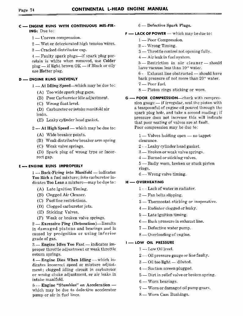
Page 74 CONTINENTAL L-HEAD ENGINE MANUAL
c- ENGINE RUNS WITH CONTINUOUS MIS-FIR-ING: Due to:
1 -- Uneven compression.
2 -- Wet or deteriorated high tension ~vires.
3 -- Cracked distributor cap.
4 -- Faulty spark plugs--if spark plug por-celain is white when removed, use Colderplug -- if light brown OK -- if Black or oilyuse Hotter plug.
D ~ ENGINE RUNS UNEVENLY
1 -- At Idling Speed--which may be due to :
(A) Too wide spark plug gaps.
(B) Poor Carburetor idle adjustment.
(C) Wrong float level.
(D) Carburetor or intake manifold airleaks.(E) Leaky cylinder head gasket.
2 -- At High Speed -- which may be due to :
(A) Wide breaker points.
(B) Weak distributor breaker arm spring
(C) Weak valve springs.
(D) Spark plug of wrong type or incor-rect gap.
E m ENGINE RUNS IMPROPERLY
1 -- Back-Firing into Manifold -- indicatesToo Rich a fuel mixture ; into carburetor in-dicates Too Lean a mixture--may be due to :
(A) Late Ignition Timing.
(B) Clogged Air Cleaner.
(C) Fuel line restrictions.(D) Clogged carburetor jets.
(E) Sticking Valves.
(F) Weak or broken valve springs.
2-- Excessive Ping (Detonation) Resultsin damaged pistons and bearings and iscaused by pre-ignition or using inferiorgrade of gas.
3 -- Engine Idles Too Fast -- indicates im-proper throttle adjustment or weak throttlereturn springs.
4 ~ Engine Dies When Idling- which in-dicates incorrect speed or mixture adjust-ment; clogged idling circuit in carburetoror wrol~g choke adjustment, or air leaks inintake manifold.
5- Engine "Stumbles" on Acceleration mwhich may be due to defective acceleratorpump or air in fuel lines.
6 -- Defective Spark Plugs.
LACK OF POWER -- which may be due to :
1 -- Poor Compression.
2 -- Wrong Timing.
3 -- Throttle control not opening fully.
4 -- Air leak in fuel system.
5--Restriction in air cleaner--shouldhave vacuum less than 10" water.
6 -- Exhaust line obstructed -- should haveback pressure of not more than 20" water.
7 -- Poor fuel.
8- Piston rings sticking or worn.
-- POOR COMPRESSION--check with compres-sion gauge -- if irregular, seal the piston witha teaspoonful of engine oil poured through thespark plug hole, and take a second reading; ifpressure does not increase this will indicatethat poor seating of valves are at fault.Poor compression may be due to:
1 -- Valves holding open -- no tappetclearance.
2 -- Leaky cylinder head gasket.
3 -- Broken or weak valve springs.
4 -- Burned or sticking valves.
5 -- Badly worn, broken or stuck pistonrings.
6 -- Wrong valve timing.
~ OVERHEATING
1 -- Lack of water in radiator.
2 -- Fan belts slipping.
3- Thermostat sticking or inoperative.
4 -- Radiator clogged or leaky.
5 -- Late ignition timing.
6 -- Back pressure in exhaust line.
7 -- Defective water pump.
8 -- Overloading of engine.
LOW OIL PRESSURE
1 -- Low Oil level.
3--
4--
5--
6--
7--
81
Oil pressure gauge or line faulty.
Oil too light -- diluted.
Suction screen plugged.
Dirt in relief valve or broken spring.
Worn bearings.
Worn or damaged oil pump gears.
Worn Cam Bushings.

CONTINENTAL L-HEAD ENGINE MANUAL Page 75
J m HIGH OIL PRESSURE--should not exceed rec-ommended pressures except when engine isstarting up cold. Abnormally high oil pressureis not desirable because it increases, oil con-sumption --- possible causes of high oil pres-sures are :
1 -- Engine oil too heavy.
2 -- Stuck relief valve.
3 -- Obstruction in distributing line.
4 -- Faulty oil pressure gauge.
K ~ HIGH OIL CONSUMPTION
1 -- Oil leaks.2 -- Too high oil level.
3 -- Incorrect grade of oil used.
4 -- Clog~:ed crankcase breather.
5--Oil pressure too high -- stuck reliefvalve.6--Pisto~a rings not run-in, due to toosmooth cylinder bore finish or glazed con-dition.
7 -- Worn, broken or stuck piston rings andclogged oil control rings.
8 -- Worn pistons and sleeves.
9 -- Worn bearings.
10 -- Worn valve guides.
(Manifold may be removed for visual inspec-tion.)
L m ENGINE KNOCKS AND OTHER NOISES1 -- Operating Knocks -- which may be dueto:
(A) Pre-Ignition--Most common causeis due to wrong type plugs which are toohot.(B) Carbon -- noticeable when engine accelerated while hot--clean head andpistons.
(C) Timing--early timing causes knockssimilar to carbon -- but may tend to kickback when starting.
(D) Fuel--detonation knock caused poor gas.
(E) Overloads -- particularly at loweroperating speeds.
2 -- Mechanical Knocks-~result from wear,abuse or i.mproper adjustments -- whichmay be due to :
(A) Crankshaft and Main Bearings:(1) Worn or burned-out Main Bearings--A heavy, dull knock when accelerat-ing urtder load. Locate by shorting outplugs on both sides of the bad bearing.(2) Crankshaft End-Play-- excessiveend-play is indicated by an intermittent
knock which will come and go when theload is released and engaged.
(B) Connecting Rod Bearings(1) Worn or Burned-out Bearings --The worst condition, a light pound ormetallic knock, is noted at idling and toabout 2~ maximum speed. Bad bear-ings can be determined by shorting outplugs.
(C) Pistons and Wrist-Pins(1) Loose Wrist Pins--noise doubleswhen the correct plug is shorted out --most noticeable at idling speed.
(2) Piston Loose in Cylinder--"Pis-ton-Slap" is noted by metallic knockingat low speed under load ; but disappearsat high speed -- also most noticeablewhen starting cold--test by shortingout plugs.
(D) Broken Piston Ring or Pinsharp clicking noise that won’t short out.
(E) Valves(1) Burned Valves and Seats -- enginemisses, especially at low speeds, or ac-celeration under load.
(2) Weak or Broken Valve Springs --missing at low or high speeds when un-der load.
(3) Sticking Valves -- loss of powerand popping sound when bad.
(4) Tappet noise -- excesgive clear-ances cause noise when cold -- whichdiminishes at normal operating temper-ature.
(F) Camshaft -- Noise due to loose bear-ings or end play -- usually occurs at halfengine speed.
(G) Timing Gear Noise -- Loose or worngears rattle or knock -- tight gears hum.
3 -- Vibration Originating at Engine -- Themost common sources of vibration originat-ing in or on the engine, as distinguishedfrom causes created outside the engine areas follows :
(A) Misfiring
(B) Misalignment of engine
(C) Bent or off-center coupling
(D) Engine loose on bed and type mountings.
(E) Out of balance condition of flywheeland clutch assembly.
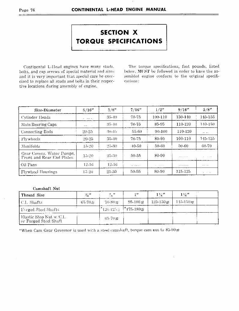
Page 76 CONTINENTAL L-HEAD ENGINE MANUAL
SECTION XTORQUE SPECIFICATIONS
Continental L-tIead engines have many studs,bolts, and cap screws of special material and sizesand it is very important that special care be exer-cised to replace all studs and bolts in their respec-tive locations during assembly of engine.
The torque specifications, foot pounds, listedbelow, MUST be followed in order to have tile as-semi)led engine conform to the original specifi-cations :
Size-Diameter 5/16" 3/8" 7/16" 1/2" 9/16" 5/8"
(:ylinder IIeads ..... 35-.lO 70-75 100-110 130-140 145-155
Main Bearing Caps _. :~5-.10 70-75 85-95 110-120 I d0-150
Connecting Rods 20-25 .lo-.15 55-60 90-100 110-120
Flywheels 20-25 35-40 70-75 85-95 100-110 145-155
Manifolds 15-20 25-3(I 40-50 50-60 50-60 (;0-70
(lear Covers, Water Puml)s,Front and Rear End Plates 15-20 25-30 50-55 80-90
Oil Pans 12-16 12-16 .............................
Flywheel IIousings 15-20 25-30 50-55 80-90 115-125 _
Camshaft Nut
Thread Size
(;.I. Shafts
l",.rged Steel Shafts
Elastic Stop Nut w.’C.1.or Forged Steel Shaft
¾" ?h" 1" 1%" 1 ¼"
7()-8()~- 125-130-~. 115-15(Igg65-7O_# 95-100:~l, 175-180-~
*When Cam Gear Governor is used with a steel can>haft, torque cam nut to 85-90~

CONTINENTAL L-HEAD ENGINE MANUAL Page 77
SECTION Xl
LIMITS AND CLEARANCE DATA
NOTE: DIMENSIONS SHOWN ARE FORSTANDARD ENGINES
Engine Model N-S6N-62
Y-69Y-91Y-112
F-124F-140F-162F-244
F-186F-209F-226
F-135F-163F-227F-245
M-271M-290M-330M-363
B-371B-427
INTAKE INTAKE INTAKE INTAKE INTAKEVALVE GUIDE AND AND AND AND AND INT. EXH. INT. EXH.
EXHAUST EXHAUST EXHAUST EXHAUST EXHAUST
Length 12~2 2~2 2~6 2~6 2~e 3~ 3.0 2~
.56~5/.5635
.31 (,9/.3159
.311~4
.6575/.6565
.3432/.3422
.3447
.6575/.6565
.3432/.3422
.3447
Outside Oia.Stem Hale Dia.
*Wear Limits--Max. Dia.Distance, Cyl. BlockContact Face to Guide
.6575/.6565
.3432/.3422
.3447
.5645/.$63S.3167/.31S7.3182
.752/.751
.4067/.4057
.4082
.814/.813
.4370/.4360.4385
VALVES, INTAKE
Stem Dia.*Wear Limits, Mia. Oia.Seat AngleStem Clearance Limits
*Wear Limits--Max. CI.Desired Stem Clear.
.3149/.3141
.312130°
.001/.0006
.003
.0008
.3149/.3141
.312130°
.OOl/.OOO6
.003.0008
.3414/.3406
.338630°
.0026/.0008
.0046
.0015
.3414/.3406
.338630°
.oo26/.ooo8
.0046
.0015
.3414/.3406
.338630°
.oo26/.ooo8
.0046.0015
.4037/.4026
.400630°
.0036/.002
.0056
.002
.4340/.4329
.430930°
.0036/.002
.0056
.002
VALVES, EXHAUST
Stem Oio."Wear Limits--Min. Dia.Seat AngleStem Clearance--Limits
"Wear Limits, Max. CI.Desired Stem CI.
VALVE SPRINGS
Outside Dia.ler~gth--VaNe closedLoad--Valve closed
’Wear Limits--Min. Wgt.length--Valve openLoad--Valve open
"Wear Limils--Min Wgt.
.3132/.3124
.0047/.0043.006:3.003:i
.3132/.3124
.310445°
.0047/.0043.0063.0035
.338S/.3377
.33574S°
.0055/.0037
.0075
.0045
.3385/.3357
.33574So
.0055/.0037
.00.7S
.0045
.3385/.3377
.33574S°
.0055/.0037
.0075
.0045
.4014/.4007.3987
45°
.0055/.0043
.0075
.0045
18-2216 #
32-3829 ~
47-53#42 ~I~
96-104 ~86 :
31//32
47-53~
42=
96-104=86--
1.150/1.130
47.53=‘
42#
103-110~93±=
47-53 ~42 :
96-104 =86 ~
1.302/1.282
58-64=52--1.521
115-123--103:
.4315/.4305
.42854S°
.006/.0045
.008
.0045
1.6176S3~-72!~
59 =1.316
137-151123 =

LIMITS AND CLEARANCE DATA
Engine Model N-56N-62
Y-67Y-91Y-112
F-124F-140F-162
CAMSHAFT
F-135"*** F-186F-163"*** F-209
F-226F-244
M-271M-290M-330M-363
B-371B-427
Brg. Journal Dia. #I#2#3#4
*Wear Limits--Mb. Dia.Bushing--inside Dia. #1
#2#3
Bushing--Clearance LimitsEnd Play
1.7465/1.74551.7465/1.74551.2465/1.2455
None
1.750/1.7491.750/1.7491.250/1.249(No Bushings).0045/,0025.007/.003
1,8095/1.80851,7465/1.74571.2475/1.2465
None
1.8125/1.81151.7502/1.74951,2505/1.2495
None.oo4/.oo2.007/.003
1.8725/1,87151.7465/1.74571.2475/1.2465
None
1.8755/].8745t.7502/1.74951.2505/1.2495
None.004/.002.oo9/.oo5
1.8725/1.8715 1.8725/1.8715 1.8725/1.87151.7465/1.7455 1.8095/1.8085 1.8095/1.80851.2475/1.2465 1.7465/1.7457 1.7465/1.7457
None 1.2475/1.2465 1.2475/1.2465/.001 UNDER MINIMUM NEW SHAFT DIAMETER)
1.8755/1.8745 1.8755/1,8745 1.8755/1.87451.7502/1.7495 1.8125/1.8115 1.8125/1.81151.2505/1.2495 1.7502/1.7495 1.7502/1.7495
None 1.2505/1.2495 1.2505/1.2495.004/.002 .004/.002 .004/.002.009/.005 1009/.005 .009/.005
CONNECTING RODS
1.8725/1.87151.8095/1.80851.7465/1.74571.2475/1.2465
1.8755/1.87451.8125/t.811S1.7502/1.74951.2505/1.2495.oo4/.oo2.009/.005
2.1850/2.18402.1225/2.12152.0600/2.05901.7475/1.7465
2.1870/2.18652.1245/2.12402.0620/2.06151.7495/1.7490.003/.0015.oo8/.oo5
2.2430/2.24202.2430/2.24202.2430/2.24202.2430/2.2420
2.2450/2.24452.2450/2.24452.2450/2.244S2.2450/2.2445.003/.00]5.oo9/.oo5
Bush. Hole I)ia.Brg. Hole Dia.Brg. Thickness*Wear Lirnits--Min. Thk,Dia.--Crank Pin
"Wear Limits--Min. Dia.Clearance LimitsOesired Clearance
*Wear Limits--Max, CI.Side PlayDesired Side Play
MAIN BEARINGS
.6067/.60571.6240/1.6245
,06175/.06150
.0610
.500-1.499
.498
.0005/.0025.0015.0035
.010/.006
.006
,7632/.76221.6245/1.6240
.0617/.0614
.0609
1,500-1.499
1,498.0006/.0027
.0015,0037
,0105/.006,0065
.914/.9132.0620/2.0615
.0617/.0614
.0609
1.9375/1.9365
1.9355.0006/.0027
.0015
.0037
.010/.006,006
.914/.9132.1870/2.1865
.0616/.0613
.0608
2.0627/2,0619
2.0609
.0006/.0022.0015.0032
.010/.006.006
.914/.9132.0620/2.0615
.0617/,0614
.0609
1.9375/1.9365
1.9355
.0006/.0027.0015.0037
.010/.006
.006
.914/.9132.1870/2.1865
.0616/.0613
.0608
2.0627/2.0619
2.0609
.0006/.0022.gOT5
.0032
.010/.006
.006
.914/.913
2.1870/2.1865.0616/.0613
.0608
2.0627/2.0619
2.0609
.0006/,0022.0015.0032
.010/.006
.006
1.313/1.3122.3745/2.3740
.0621/.0618
.0613
2.248/2.249
2,247.0008/.0029
.0015
.0039
.010/.006
.006
1.500/1.499
2.6870/2.6865.0933/.0930
.0925
2.498/2.499
2.497.0009/.0030
.0015
.004
.010/.006
.006
Dia. of Brg. Bore in BlockBrg. Thickness"Wear Limits--Min. Thk.Dia. of Main Brg. Jr.
*Wear Limits--Min. Dia.Clearance LimitsDesired ClearanceC/S End Play.
2.1710/2.1703.08475/.08450
.0840
2.000/1.9991.998
.003/.0008
.0015
.OO3/.OO8
1.8747/1.8740
.0625/.0622
.06171.7485/1.7475
1.7465
.0005/.0028.0015
.003/.008
2.4372/2.4365
.0926/.0929.0921
2.250/2.249
2.248
.O007/.003O.0015
.003/.008
2.5622/2.5615
.0925/.0928
.0920
2.3752/2.37442.3734
.0007/.0028
.0015,002/.006
2.4372/2.4365
.0926/.0929.0921
2.250/2.2492.248
.0007/.0033
.0015
.003/.008
2.5622/2.5615
.0925/.0928
.0920
2.3752/2.37442.3734
.0007/.0028
.0015
.003/.008
2.5622/2.5615
.0925/.0928
.0920
2.3752/2,37442.3734
.0007/.0028.0015
.002/.006
2.8122/2.8115
.0930/.0933
.0925
2.624/2.6232.622
.0009/.0032
.0020
.003/.008
3.0622/3.0615
.0930/.0933.0925
2.874/2.8732.872
.0009/.0032
.0020
.003/.008
PISTON PIN See Note 1 See Note 2 See Note 7 See Note 3 See Note 4 See Note 4 See Note 5 See Note 6LengthDiameter
*Wear Limits--Min. Dia.Desired FitBush. Hole Dia.--Fin.
*Wear Limits--Max. Dia.Pin CI. in BushingDesired Pin Fit
1.925/I.920.5435/.5433.5430
Light Push.5438/.5436.5448.ooo5/.OOOl.0003
2.066/2.056.7085/.7083,7080
Light Push.7089/.7087.7099.0006/.0002.0004
2.504/2.489.8593/.8591.8588. Light Push.8597/.8595.8607.0006/.0002.0004
2.878/2.868.8593/.8591.8588
Light Push.8597/.8595.8607.0006/,0002.0004
2.504/2.489.8593/.8591.8588
Light Push.8597/,8595.8607.ooo6/,ooo2.0004
2.815/2.805.8593/.8591.8588
Light Push.8597/.8595.8607,0006/.0002.0004
2.868/2.878.8593/.8591.8588
Light Push.8597/.8595.8607.0006/.0002.0004
3.190/3.1751.1093/1.1091.8588
Light Pusht.1097/1.10951.1107.0006/.0002.0004
3.365/3.3551,2500/1.24981.2495
Light Push1.2504/1.25021.2514.0006/.0002.0004
NOTE 1 --Y-91 PISTONPIN LENGTH2.441 /2,431Y.112PISTONPIN LENGTH2.7553/2.1543
NOTE 2--F-140 PISTONPIN LENGTH2.691 /2,676
F-162PISTONPIN LENGTH2,878 /2.~68
NOTE3-- F-209 PISTON PIN LENGTH 2,691 /2676
NOTE4--F-244 PISTON PIN LENGTH 2.878 /2.868
NOTE S--M-27t PISTON PIN LENGTH 3.065/3.050
M-330 PISTON PIN LENGTH 3,440/3.425
M-363 PISTON PIN LENGTH 3.440/3.425
NOTE 6--B-422 PISTON PIN LENGTH 3.630/3.620
NOTE 7--F135 Piston Pin Length 2.691/2.676** F245
Rear Flange gearingThickness .................................... .0926 - .09290
*Wear Limits, Min. Thickness ........................ .0921
*** F227Camshaft gearing Journal Dia ~-3 ................ ].7465 -1.7455Bear Flange Bearing
Thickness ......................... .0926 - .09290*Wear LimHs, Min Thickness ................... .0921
***’ F13S and F163Center Flange Bearing
Thi(kness .............................................. .0926 - .09290*Wear Limits, Min Thickness .......................... .0921Clearance Limits .......................................... :0005 - ,0026
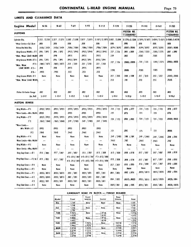
CONTINENTAL L-HEAD ENGINE MANUAL Page 79
LIMITS AND CLEARANCE DATA
Engine Model N-56 N-62 Y-69 Y-91 Y-i12 F-124 F-135 F-140 F-162 F-163
PISTON NO. PISTON NO.PISTONS F135A00402 F163A00403
:ylinder Dia.
*Wear Limits--Cyl. Bore
Piston Pin Hole Dio.
Ring Groove Width--# 1 :
*Max. Wear Limit Width
Ring Groove Width #2--
*Max. Wear #3--
Limit Width #2--
#3--Ring Groove Width #4
*Max. Wear Limit Width
Piston Fit-Feeler Gauge
Lbs. Pull
2.252 /2.250
.008
.5436/.5434
.096 /.095
.098
.096 /.095
.1885/.1875
.098
.1905
None
.002
5-1(1#
2.377 /2.37S
.008
.5436/.5434
.o9~ /.o9s
.098
.096 /.095
.i885/.187s
.098
.1905
None
.002
5-10#
2.so2/2.500.008
.7086/.7084
.0955/.0945 1
.0975
.0955/.094
.251/.2so.0975
.253
None
.002
5-10#
2.877 /2.875
.008
.7086/.7084
.0955/.0945
.0975
.0955/.094
.251 /.2S0
.0975
.253
None
.002
5-10#
3.1875/3.1895
.008
.7086/.7084
.0955/.0945
.0975
.0955/.094
.251 /.250
.097S
.253
None
.002
S-10#
3.002 /3.000
.008
.8594/.8592
.127 /.126
.129
.127 /.126
.1290
.251 /.250
.253
.003
S-lO#
3.1270/3.1250
.008
.8597/.8595
.081 /.080
.083
.0965/.0955
.0985
.189 /.188
.191
.003
5-10#
3.1895/3.1875
.008
.8594/.8592
.1265/.1255
.1285
.126/.125
.1280
.251 /.250
.253
.003
S-lO#
3.4395/3.4375
.008
.8597/.8595
.1285/,127S
.1305
.1285/.1275
.1305
.2S3 /.252
.255
.003
5-10#
3.4395/3.4375
~06
.8597/.8595
¯ 81 ./.080
.083
.0965/.0955
.0985
.2515/.2505
.2535
PISTON RINGS
Ring Width--# 1
*Wear Limits--Min. Width
Ring Width--# 2
#3*Wear Limifs--
Min. Width #2
#3Ring Width-- # 4
Wear Limits--~tin. Width
Ring Width-- # 5
Wear Limits--Min. Width
Ring Gap Clear.--# 1
Ring Gap Clear.--#2 & 3
Ring Gap Clear.--#4
Ring Gap Clear.--# 5
Ring Side Clear.--# 1
Ring Side Clear.--# 2
#3Ring Side Clear.--#4
.0935,/.0925
.0905
.0935,/.0925
.1865,/.1860
.0905
.1840
None
Nolle
.013 /.005
.013 /.OOS
None
None
.0035/.0015
.0035/’.0015
.0025/.001None
.0935/.0925
.0905
.0935/.0925
.1865/.1860
.0905
.1840
None
None
:017 /.007
.017 /.007
None
None
.0035/.0015
.0035/.0015
.0025/.001
None
.0935/.0925
.0905
.0935/.0925
.249 /.2485
.0905
.2465
None
None
.015 /.007
#2-.015/.00)
#3-.013/.005
None
None
.003 /.001
.003 /.001
.0025/.001None
.0935/.0925
.0905
.0935/.0925
.249 /.2485
.0905
.2465
None
None
.OlS /.007#2-.OlS/.oo:#3-.o13/.oo
None
None
.0025/.001
.0025/.001
.oo25/.oolNone
Model
N62
Y400
F400
F60Q
M600
8600
CAMSHAFT BORE IN
FrontFront Interm.
1.749 None1.7481.750 None1.7491.9375 None1.93702.0000 None1.99952.0000 1.93751.9995 1.93702.3750 2.31252.3740 2.31152.3750 2.37502.3740 2.3740
.0935/.0925
.0905
.0935/.0925
.249 /.2485
.0905
.2465
None
None
.o13 /.oo8#2-.013/,008
#3-.016/.008
None
None
.003 /.001
.003 /.001
.oo2s/.OOlNone
.124 /.123
.121
.124 /.123
.121
.249 /.2485
.2465
None
.013 /.008
.013 /.008
.0T7 /.007
None
.004 /.002
.oo4/.oo2
.0025/.001
.078 /.077
.075
.094 /.093
.091
.188 /.184
.182
None
.008 /.018
.008 /.018
.015 /.055
None
.002 /.004
.0015/.0035
.000 /.005
.124 /.123
.121
.124 /.123
.121
.249 /.2485
.2465
None
.017 /.007
.017 /.007
.016 /.008
None
.0035/.0015
.0035/.0015
.0025/.001
BLOCK--FINISH REAMED
RearCenter Interm. Rear
None None 1.2491.248
None None 1.2501.249
1.8750 None 1.37501.8745 1.37451,8750 None 1.37501.8740 1.3745None 1.8750 1.3750
1.8745 1.3745None 2.2500 1.9375
2.2490 1.9365None 2.3750 2.3750
2.3740 2.3740
.124 /.123 .078 /.077
.121 .075
.124 /.123 .0930/.0925
.121 .0905
.249 /.2485 .248 /.244
.2465 .242
None None
.017 /.007 .008 /.018
.017 /.007 .008 /.018
.017 /.007 .010 /.030
None None
.0055/.0035 .002 /.004
.0055/.0035 .0025/.004
.0045/.003 .0025/.0075

Page 80 CONTINENTAL L-HEAD ENGINE MANUAL
LIMITS AND CLEARANCE DATA
Engine Model F-186 F-209 F-226 F-227 F-244 F-245 M-271
PISTON NO. PISTON NO.PISTONS F227AO0406 F163AO0403
Cylinder Dia.*Wear Limits--Cyl. BorePiston Pin Hole Dia.Ring Groove Width--# 1
*Max. Wear Limit WidthRing Groove Width--#2-3
*Max. Wear Limit WidthRing Groove Width--#4
*Max. Wear Limit WidthRing Groove Width--~5
*Max. Wear LimitPiston Fit-Feeler Gauge
Lbs. Pull
3.002 /3.000.008.8594/.8592
¯129.127 /.126¯1290.251 /.250.2530
None
.0035-10#
3.1895/3.1875.008.8597/.8595.1285/.1275.1305.1285/.1275.1305.253 /.252.2550
None
.0035-10#
3.3145/3.3125.008¯8594/.8592.1265/.1255¯1285.126 /.125.1280.251 /.250.2530
None
.0O35-10#
3.3145/3.3125.008.8597/8595.081 /.080.083.0965/.0955.O985.2515/2505.2535
None
.0035.1o#
3.4395/3.4375.008.8597-.8595.1285/.1275.1305.1285/.1275.1305.253/.252.2550
None
.0035-10#
3.4395/3.4375.008.8597/.8595.081 /.080.083.0965/.0955.0985.2515/2505.2535
None
.0035-10#
3.627/3.625.0081.1o96/1.1o94.1275/ .1265.1295.1265/ .1255.1285.1895/ .1880.1915.1895/ .1880.1915.004~-1o#
PISTON RINGS
Ring Width--# 1*Wear Limits--Min. WidthRing Width--#2 8, 3
*Wear Limits--Min. WidthRing Width--#4
*Wear Limits--Min. WidthRing Width--# 5
*Wear Limits--Min. WidthRing Gap Clearance--#1Ring Gap Oearance--#2 & 3Ring Gap Clearance--#4Ring Gap Clearance--#5Ring Side Clearance--# 1Ring Side Clearance--#2 & 3Ring Side Clearance--#4Ring Side Clearance--#5
.124 /.]23
.121
.124 /.123
.121.249 /.2485.2465
Nane
.013 /.008
.013 /.008
.017 /.007None
.004 /.002
.004 /.002
.oo25/.OOlNone
.124 /.123
.121
.124 /.123
.121
.249 /.2485.2465
None
.o17 /.oo7.017 /¯007.017 /.007
None.0055/.0035.0055/.0035.0045/.003
None
.124/.123.121.124/.123.121.249 /.2485.2465
None
.O2O /.010
.020 /.010
.016 /.008None
.oo35/.oo15
.003 /.001
.oo25/.OOlNone
.078 /.077
.075
.0930/.0925
.0905
.248 /.244
.242None
.008 /.018
.O08 /.018
.010 /.030None
.002 /.004
.0025/.004
.0025/.0075None
.124 /.123
.121
.124 /.123
.121
.249 /.2485
.2465None
.017 /.007
.017 /.007
.017 /.007None
.005 /.0035
.oo55/.oo35
.0045/.003None
.078 /.077
.075
.0930/.0925
.0905
.248 /.244.242
None
.008 /.018
.008 /.018
.010 /.030Hone
.002 /.004
.0025/.004
.0025/.0075None
.124 /.123.121.124 /.123.121.1865/.1860.184.1865/.1855.1835.015 /.008.015 /.008.OlS/.oo8.o!8/.oo8.0045/.002.oo35/.ools.0035/.0015.004 /.0015

CONTINENTAL L-HEAD ENGINE MANUAL Page 81
LIMITS AND CLEARANCE DATA
IM-330 M-363 B-371 B-427Engine Model M-290
I
PISTONS
Cylinder Dia.*Wear Limits--Cyl. BorePiston Pin Hole Dia.Ring Groove Width--#1
*Max. Wear LimitsRing Groove Width--#2-3
*Max. Wear LimitRing Groove Width--#4
*Max. Wear LimitRing Groove Width--# 5
*Max. Wear LimitPiston fit-Feeler Gauge
Lbs. Pull
3.752/3.750.008
1.1096/1.1094.1275/ .1265,1295.1265/ .1255.1285
,1915.1895/ .1880.1915.005
5-10#
4.002/4.000.008
1.1096/1.!094.1275/ .1265.1295.1265/ .1255.1285.1895/.1880.1915.1895/ .1880.1915.005
5o10#
4.000 /3.9995.008
1.1097/I.1095.0975/.0965.0995.0975/ .0965.0995.1885/ .1875.1915.1895/ .1880.1915.003
5-10#
4.127 /4.125.008
1.2503/1.2501.1275/ .1265.1295.1265/ .1255.1285.251 / .250.2530
.1905
.0055-10#
4.3145/4.3125.008
1.2503/1.2501.0975/ .0965.0995.0975/ .0965.0995.251 / .250.2530.1885/ .1875.1905.0055-10#
PISTON RINGS
Ring Width--# 1*Wear Limits--Min. WidthRing Width--# 2 & 3
*Wear Limits--Min. WidthRing Width--#4
*Wear Limits--Min, WidthRing Width--#5
*Wear Limits--Min. WidthRing Gap Clearance--#1Ring Gap Clearance--# 2Ring Gap Clearance-- #4Ring Gap Clearance--# 5Ring Side Clearance--# 1
Ring Side Clearance--# 2
Ring Side Clearance--# 4Ring Side Clearance--# 5
&3
&3
.124 /.123
.121
.124 /.123
.121
.1865/.1860
.184
.1865/,1855
.1835
.013/.008
.018/.008
.018/.008.018/.008.004s/.0025.0035/.0015.0035/.0015.004/.OOLS
.124 /.123
.121
.124 /.123.121.1865/.186o.184.1865/.1855.1835.o13/.o08.016 /.011.020/.OLO.016 /.011.0O45/.0025
.oo35/.OOlS
.0035/.0015
.004 /.0015
.0935/.0930
.0910
.0935/.0930
.0910
.1865/.1860
.1840
.1865/.1860
.1840.025 /.013.023 /.013.o23/.o13.023 /.013.0045/.003
.0045/.003
.oo25/.OOl
.0035/.0015
.124 /.123
.121
.124 /.123.121.249 /.2485.2465.1865/.1855
..1835.o16/.Oll.016 /.011.o17/.007.o17/.oo7.0045/,0025
#2--.0045/.0025#3--.0035/.0015
.0025/.001.oo3/.OOl
.0935/.0930
.0910
.0935/.0930
.0910.249 /.2485.2465.186s/.18ss.1835.023 /013.023 /.013,023 /.013.023 /.013.0045/.003
.oo45/.oo3
.o~25/.OOl
.0025/.001

SERVICE AND PARTSAvailable from your Authorized
WISCONSINService Center
SALES OFFICE:2020 Fletcher Creek Drive, Memphis, Tennessee 38133
Phone: (901) 371-0353 or Toll Free (800) 932-2858www.wisconsinmotors.com
JUN 2006X-27053A
! WARNING !
California Proposition 65The engine exhaust from this product contains chemicals known to the State of California to cause cancer, birth defects or other reproductive harm.
WISCONSINMOTORS, LLC