overview - boston scientific › content › dam › ...integration technical application...
TRANSCRIPT

EMR Integration Testing Scenarios - 357742-003
Page 1
LATITUDE® Patient Management
Contents
Overview............................................................... 1 Testing Scenarios Overview ................................. 2 Live Production Systems Testing.......................... 3
Preparation ..................................................3 Process ........................................................4 Post Test Cleanup .......................................4 Expected Results .........................................5 Troubleshooting Tips ...................................5
Insert Message at LTS with Debug Mode............. 8 Preparation ..................................................8 Process ........................................................9 Post Test Cleanup .....................................10 Expected Results .......................................10 Troubleshooting Tips .................................11
Live Production Systems with Debug Mode ....... 13 Preparation ................................................13 Process ......................................................14 Post Test Cleanup .....................................14 Expected Results .......................................15 Troubleshooting Tips .................................15
Appendix A - The LTS Initialization File .............. 19 Appendix B - The LTS Log File...........................20 Appendix C – Example HL7 Message from LATITUDE...........................................................21 Appendix D – Example .HR Message from LTS.25 Appendix E – Example .HT Message from LTS .29
Overview User acceptance testing will be performed at the end of each customer installation to prove that data is flowing from the LATITUDE system, through the EMR Integration feature, to the customer’s EMR system.
It will show that a specific patient’s data is delivered as a “Lab Result” to the clinic’s EMR system and that once that data is signed by the physician it is available for viewing in the patient’s flow sheet.
Specifically the procedures below will show:
• Successful security credential functionality
• Proper configuration of the LATITUDE/Logician EMR Integration feature
• LATITUDE physician to CPO physician matching
• Patient data flowing to a physician’s Logician desktop
Procedures do not necessarily prove that the data elements will work with customer developed forms or reports.
This document assumes the reader is familiar with the processes and concepts presented in the LATITUDE EMR Integration Technical Application Overview, 357729-002.
Your existing Logician / CPO technical and user documentation should be used to understand the proper use of the Logician / CPO product.
EMR Integration Testing Scenarios - 357742-003
Page 2
LATITUDE® Patient Management
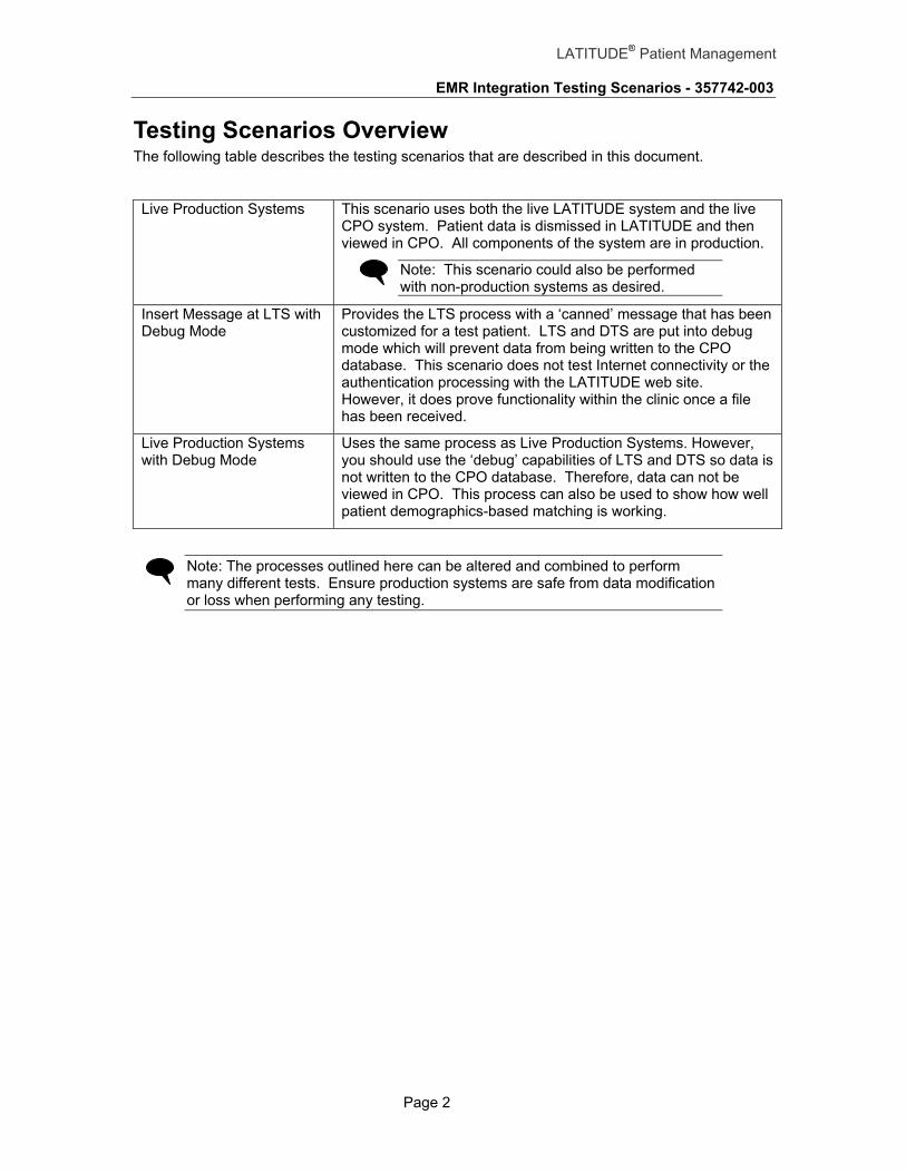
Testing Scenarios Overview The following table describes the testing scenarios that are described in this document.
Live Production Systems This scenario uses both the live LATITUDE system and the live CPO system. Patient data is dismissed in LATITUDE and then viewed in CPO. All components of the system are in production.
Note: This scenario could also be performed with non-production systems as desired.
Insert Message at LTS with Debug Mode
Provides the LTS process with a ‘canned’ message that has been customized for a test patient. LTS and DTS are put into debug mode which will prevent data from being written to the CPO database. This scenario does not test Internet connectivity or the authentication processing with the LATITUDE web site. However, it does prove functionality within the clinic once a file has been received.
Live Production Systems with Debug Mode
Uses the same process as Live Production Systems. However, you should use the ‘debug’ capabilities of LTS and DTS so data is not written to the CPO database. Therefore, data can not be viewed in CPO. This process can also be used to show how well patient demographics-based matching is working.
Note: The processes outlined here can be altered and combined to perform many different tests. Ensure production systems are safe from data modification or loss when performing any testing.

EMR Integration Testing Scenarios - 357742-003
Page 3
LATITUDE® Patient Management
Live Production Systems Testing
This process moves patient data from the LATITUDE system into the CPO system for viewing in the patient’s flow sheet. The process is performed in a production environment with production data. Ensure appropriate care is taken when using production systems.
Note: This process can also be used in a non-production environment. To ensure no data is lost or overwritten, only those familiar with the integration feature should attempt to use non-production environments.
Clinic Environment
Home Environment
LATITUDECommunicator
Logician / CPO Database
Internet
Patient
Logician / CPO Server
DTSLTS
LinkLogic InboxFolder
Logician / CPO Client
Web Browser
Clinician
LATITUDE - GE Logician / CPO IntegrationLive Production Systems
Boston Scientific
LATITUDE Secure Server
Preparation The following steps should be completed to prepare to run this test scenario. Use the appropriate configuration management steps for your site before proceeding.
1. On the DTS server, find the LTS.INI file - normally installed in <DTS Install Directory>\Logician\Latitude\lts.ini.
2. Create a copy of the LTS.INI file and call it LTS.INI.ORG (for original)
3. Edit LTS.INI and change the following entries.
a. POLLLINGINTERVAL=10
b. SAVEDIR=C:\Program Files\Logician\Latitude\save (Assuming the installation files are located in C:\Program Files\...)
4. Restart the LTS service to use the new LTS.INI settings.

EMR Integration Testing Scenarios - 357742-003
Page 4
LATITUDE® Patient Management
Process 1. Ensure the desired installation and configuration of the GE LTS packages are complete
by following the LATITUDE-Logician\EMR Installation and Configuration guide.
2. Ensure the Preparation steps listed above have been completed.
3. The LATITUDE physician logs into LATITUDE.
4. From the Patients for Review page, select a patient that has reviewable device data.
Note: This is production data and all normal review procedures should be followed.
5. Once the review is complete, click the Dismiss Patient button to remove the patient from the Patients for Review page and to generate an HL7 message.
6. LTS will login and query the clinic’s LATITUDE WebDAV folder as configured in the LTS.INI file (the preparation steps above will ensure proper configuration for this testing scenario). When LTS sees the file in the web folder, it will transfer the file to the clinic for processing.
7. Once the file is received, LTS will transform the single HL7 message into two HL7 files and deposit them in the LinkLogic inbox.
8. DTS monitors the LinkLogic inbox as configured in CPO. When unprocessed files are present, DTS will:
a. Read those files
b. Enter data elements into the CPO database
c. Append a Q to the end of the filename (e.g., 123456.HTQ)
9. The physician logs into CPO.
10. Navigate to the physician’s inbox to see the incoming “Interrogation Lab Report.”
11. The physician reviews the lab report and then signs the report.
Note: This is production data and all normal review procedures should be followed.
12. The physician navigates to the patient’s record and opens the Flow Sheet to see the individual data elements from the imported device interrogation.
13. The physician navigates to the patient’s Documents and clicks on the Lab Report.
14. The physician clicks on the attachment (e.g., paper clip) which opens a web browser and connects to the LATITUDE web site.
15. Follow the steps in the Post Test Cleanup section to return the system to a normal operational state.
Post Test Cleanup The following steps should be completed after this scenario has been executed. Use the appropriate configuration management steps for your site before proceeding.
1. On the DTS server, find the LTS.INI file - normally installed in <DTS Install Directory>\Logician\Latitude\lts.ini.
2. Assuming the Preparation steps above were followed,
a. Delete the LTS.INI file.
b. Rename LTS.INI.ORG to LTS.INI

EMR Integration Testing Scenarios - 357742-003
Page 5
LATITUDE® Patient Management
3. Alternatively, edit the LTS.INI file and change the following entries:
a. POLLLINGINTERVAL=60
b. To save the incoming HL7 files leave the following parameter as is. SAVEDIR=C:\Program Files\Logician\Latitude\save (Assuming the installation files are located in C:\Program Files\...) Otherwise, so incoming HL7 files are not saved, change it to: SAVEDIR=
4. Restart the LTS service to use the new LTS.INI settings.
Expected Results The following table describes the expected results for specific steps in the process.
Step Expected Results
3 The Physician is able to login to LATITUDE. Shows the account is active.
4 The patient’s detail summary page is displayed.
5 The patient is removed from the Patients for Review page and an HL7 message is created for the clinic to retrieve.
6 LTS retrieves the file from LATITUDE. LATITUDE marks the data as retrieved on the EMR Log status page. The HL7 file is written to the “save” directory as configured in LTS.INI
7 Two files (*.HT and *.HR) are written to the LinkLogic inbox as configured in DTS.
8 The two files from Step 6 have been renamed *.HTQ and *.HRQ.
10 An interrogation lab report entry appears in the physician’s CPO inbox.
12 Data is visible in the flow sheet for the specific interrogation date. The HL7 file will also include other columns for other observation reports. See the “OBR Segment” subsection of Appendix A of the “LATITUDE – EMR Integration Technical Application Overview” document for details.
14 The detail summary page for the patient should be displayed. The physician may be asked to login before the page is displayed.
Troubleshooting Tips The following table describes some troubleshooting tips for specific steps in the process.
Step Troubleshooting Tip
3 The user ID and password are case sensitive.
5 1. Pressing the Dismiss Patent button creates an HL7 file and places it in the EMR Outbox for the clinic.

EMR Integration Testing Scenarios - 357742-003
Page 6
LATITUDE® Patient Management
2. Go to PATIENT UTILITIES | EMR Log to check the EMR Log for an entry for the patient that was dismissed. The status should be either Transferred to Clinic (LTS has already grabbed it), or Placed in EMR Outbox (the message is waiting for LTS to grab it).
3. If there is no log entry, make sure the clinic is setup for EMR Integration by calling customer support.
6 1. Check the LTS.LOG file to ensure LTS is attempting to connect to the LATITUDE server. The LTS.LOG file is found in <Install Directory>/Logician/Latitude/lts.log. This is an example log entry format that is created when an HL7 file is not found on the LATITUDE server:
<date/time> File Name: https://<LATITUDEServer>…/files
This log entry format is used when a file is picked up from the LATITUDE server:
<date/time> File Name: <filename>.HL7
2. An important item to remember is that a log entry does NOT mean that LTS was able to successfully authenticate the LATITUDE server. If the certificate has not been installed properly or if the LATITUDE server has not been configured properly, there will be no error message in the LTS.LOG file. The only way to determine authentication errors is by calling customer support for assistance. Note that authentication errors are not quickly fixed.
3. Assuming LTS is configured to save the HL7 files (see Preparation steps), a copy of the HL7 file will be placed in the SAVEDIR location. Check that file path to see that a new HL7 file was created.
7 Check the WRITEDIR as configured in LTS.INI for the existence of two new files: <filename>.HT and <filename>.HR. When the DTS server processes the two files, it appends a Q to the filename extension, (i.e., <filename>.HTQ and <filename>.HRQ.
8 If a Q has not been added to the two filenames, check the following:
1. Is DTS running on this machine? DTS must be running and logged in to process incoming files.
2. Is the DTS inbox configured with the same path as the WRITEDIR in LTS.INI? DTS has to be monitoring the same directory to which LTS is writing the files.
9 User ID and password are case sensitive and are not necessarily the same user ID and password used to access the LATITUDE web site.
10 If all the files have been processed up to this point and a lab report does not show up in the physicians inbox, check the following:
1. Is the login ID being used in CPO the same as the physician login ID being used in LATITUDE? Dismissed patients are sent to a specific physician. The physician is determined by the physician’s login IDs in LATITUDE and CPO. When the two IDs are not identical, a mapping file is used to map LATITUDE IDs to CPO IDs.

EMR Integration Testing Scenarios - 357742-003
Page 7
LATITUDE® Patient Management
Ensure the mapping file is setup correctly. See the LTS Installation Guide for specific details about the LATITUDE_Providers.xrs mapping file.
12 If the Flow Sheet doesn’t show the data elements, make sure the lab report has been signed by the physician. Data doesn’t make it to the Flow Sheet until the physician has signed the incoming lab report.
14 Normal operation of this step is performed using one of two options and is dependant on browser settings:
1. If the physician is not logged into LATITUDE then they will be prompted for a user ID and password.
2. If the physician is currently logged in to LATITUDE then the browser will be pointed to the patient’s specific data. Some browser configurations will prevent this operation and will still require a separate login.
Note: LATITUDE logins timeout after a few minutes of inactivity.

EMR Integration Testing Scenarios - 357742-003
Page 8
LATITUDE® Patient Management
Insert Message at LTS with Debug Mode This process uses a pre-determined HL7 message to show proper LTS and DTS functionality. This procedure can be performed in production systems with production data (or by using the debug mode) or can be performed in production systems with test data. Debug mode prevents data from being written to the CPO database while ensuring LTS, DTS, patient matching, and physician matching are functioning properly. The process steps below assume debug mode is used. Ensure appropriate care is taken when using production systems.
Clinic Environment
Home Environment
LATITUDECommunicator
Logician / CPO Database
Internet
Patient
Logician / CPO Server
DTSLTS
LinkLogic InboxFolder
Logician / CPO Client
Web Browser
Clinician
LATITUDE - GE Logician / CPO IntegrationInsert Message at LTS with Debug Mode
HL7 Message
X
Data not written to CPO Database
X
Boston Scientific
LATITUDE Secure Server
Preparation The following steps should be completed to prepare to run this test scenario. Use appropriate configuration management steps for your site before proceeding.
1. On the DTS server, find the LTS.INI file - normally installed in <DTS Install Directory>\Logician\Latitude\lts.ini.
2. Create a copy of the LTS.INI file and call it LTS.INI.ORG (for original)
3. Edit LTS.INI and change the following entries.
a. POLLLINGINTERVAL=10 Causes LTS to check for new messages in the inbox every 10 seconds.
b. SAVEDIR=C:\Program Files\Logician\Latitude\save (Assuming the installation files are located in C:\Program Files\...)
c. HL7DEBUG=YES LTS sets the debug flag in the HL7 message. Specifically, it sets MSH-12 to “D” in every output file
d. TESTMODE=YES LTS writes more information to the LTS log file.
EMR Integration Testing Scenarios - 357742-003
Page 9
LATITUDE® Patient Management
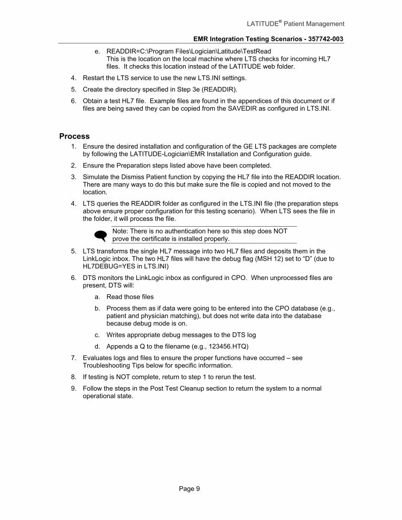
e. READDIR=C:\Program Files\Logician\Latitude\TestRead This is the location on the local machine where LTS checks for incoming HL7 files. It checks this location instead of the LATITUDE web folder.
4. Restart the LTS service to use the new LTS.INI settings.
5. Create the directory specified in Step 3e (READDIR).
6. Obtain a test HL7 file. Example files are found in the appendices of this document or if files are being saved they can be copied from the SAVEDIR as configured in LTS.INI.
Process 1. Ensure the desired installation and configuration of the GE LTS packages are complete
by following the LATITUDE-Logician\EMR Installation and Configuration guide.
2. Ensure the Preparation steps listed above have been completed.
3. Simulate the Dismiss Patient function by copying the HL7 file into the READDIR location. There are many ways to do this but make sure the file is copied and not moved to the location.
4. LTS queries the READDIR folder as configured in the LTS.INI file (the preparation steps above ensure proper configuration for this testing scenario). When LTS sees the file in the folder, it will process the file.
Note: There is no authentication here so this step does NOT prove the certificate is installed properly.
5. LTS transforms the single HL7 message into two HL7 files and deposits them in the LinkLogic inbox. The two HL7 files will have the debug flag (MSH 12) set to “D” (due to HL7DEBUG=YES in LTS.INI)
6. DTS monitors the LinkLogic inbox as configured in CPO. When unprocessed files are present, DTS will:
a. Read those files
b. Process them as if data were going to be entered into the CPO database (e.g., patient and physician matching), but does not write data into the database because debug mode is on.
c. Writes appropriate debug messages to the DTS log
d. Appends a Q to the filename (e.g., 123456.HTQ)
7. Evaluates logs and files to ensure the proper functions have occurred – see Troubleshooting Tips below for specific information.
8. If testing is NOT complete, return to step 1 to rerun the test.
9. Follow the steps in the Post Test Cleanup section to return the system to a normal operational state.

EMR Integration Testing Scenarios - 357742-003
Page 10
LATITUDE® Patient Management
Post Test Cleanup The following steps should be completed after this scenario has been executed. Use the appropriate configuration management steps for your site before proceeding.
1. On the DTS server, find the LTS.INI file - normally installed in <DTS Install Directory>\Logician\Latitude\lts.ini.
2. Assuming the Preparation steps above were followed,
a. Delete the LTS.INI file.
b. Rename LTS.INI.ORG to LTS.INI
3. Alternatively, edit the LTS.INI file and change the following entries
a. POLLLINGINTERVAL=60
b. To save the incoming HL7 files leave the following parameter as is. SAVEDIR=C:\Program Files\Logician\Latitude\save (Assuming the installation files are located in C:\Program Files\...) Otherwise, so incoming HL7 files are not saved, change it to: SAVEDIR=
c. HL7DEBUG=NO
d. TESTMODE=NO
e. READDIR=<the LATITUDE web folder URL>
4. Restart the LTS service to use the new LTS.INI settings.
5. If desired, remove the files and directory in READDIR.
Expected Results The following table describes the expected results for specific steps in the process.
Step Expected Results
3 An HL7 file should be present in the READDIR directory for a short time (max of 20 seconds) before LTS processes it and moves it to the SAVEDIR directory.
4 LTS should set the debug flag (MSH-12) in the message to “D”. This can be observed by checking the resulting file in the SAVEDIR directory or the *.HT and *.HR files in the LinkLogic inbox.
5 Two files (*.HT and *.HR) are written to the LinkLogic inbox as configured in DTS. Check them to see that the debug flag is set to “D”
6 The two files from step 5 have been renamed *.HTQ and *.HRQ. Appropriate debug messages are written to the DTS log.

EMR Integration Testing Scenarios - 357742-003
Page 11
LATITUDE® Patient Management
Troubleshooting Tips The following table describes some troubleshooting tips for specific steps in the process.
Step Troubleshooting Tip
4 1. Check the LTS.LOG file to ensure LTS is attempting to pickup a file from the READDIR directory. LTS.LOG is found in <Install Directory>/Logician/Latitude/lts.log. The following format is used for log entries when an HL7 file is not found on the LATITUDE Server:
<date/time> File Name: https://<LATITUDE Server>…/files The following format is used for log entries when a file is picked up from the LATITUDE Server:
<date/time> File Name: <filename>.HL7
2. Assuming LTS is configured to save the HL7 files (see Preparation steps), a copy of the HL7 file is placed in the SAVEDIR directory. Check that directory for a new HL7 file.
5 1. Check the WRITEDIR directory as configured in LTS.INI for two new files: <filename>.HT and <filename>.HR. When DTS processes these two files, it appends a Q to each file extension (i.e., <filename>.HTQ and <filename>.HRQ).
2. Ensure debug mode is enabled by checking the .HT and .HQ files to see that MSH-12 is set to “D”. If this flag is not set, data will be written to the CPO database.
6 1. View the DTS log files to ensure patient and physician matching was performed appropriately and that data would have been written to the CPO database as expected. The DTS log file is viewed from within the DTS application.
The following example “warning” message (Message Code 5204) from the DTS log indicates debug mode is active:
The incoming data file contains a header that requests test/debug mode. The records that follow it will not be written to the database: MSH|^~\&|LATITUDE …
The following example “warning” message (Message Code 5190) indicates the incoming patient does not match an existing patient in CPO:
IPX Warning: LinkLogic Error: No existing data could be found to match incoming data: lastName: …
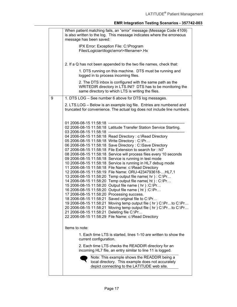
When patient matching fails, an “error” message (Message Code 4109) is also written to the log. The following message indicates where the erroneous message has been saved:
IPX Error: Exception File: C:\Program Files\Logician\llogic\error\<filename>.Hx

EMR Integration Testing Scenarios - 357742-003
Page 12
LATITUDE® Patient Management
2. If a Q has not been appended to the two file names, check that:
1. DTS running on this machine. DTS must be running and logged in to process incoming files.
2. The DTS inbox is configured with the same path as the WRITEDIR directory in LTS.INI. DTS has to be monitoring the same directory to which LTS is writing the files.
7 1. DTS LOG – See number 6 above for DTS log messages.
2. LTS.LOG – Below is an example log file. Entries are numbered and truncated for convenience. The actual log does not include line numbers.
01 2006-08-15 11:58:18 ----------------------------------------------------------- 02 2006-08-15 11:58:18 Latitude Transfer Station Service Starting. 03 2006-08-15 11:58:18 ----------------------------------------------------------- 04 2006-08-15 11:58:18 Read Directory : c:\Read Directory 05 2006-08-15 11:58:18 Write Directory : C:\Pr… 06 2006-08-15 11:58:18 Save Directory : C:\Save Directory 07 2006-08-15 11:58:18 File Extension to search for : hl7 08 2006-08-15 11:58:18 Service will process files every 10 seconds 09 2006-08-15 11:58:18 Service is running in test mode 10 2006-08-15 11:58:18 Service is running in HL7 debug mode 11 2006-08-15 11:58:18 File Name: c:\Read Directory 12 2006-08-15 11:58:19 File Name: ORU-4234793618-…HL7,1 13 2006-08-15 11:58:20 Temp output file name( hr ) : C:\Pr… 14 2006-08-15 11:58:20 Temp output file name( ht ) : C:\Pr… 15 2006-08-15 11:58:20 Output file name ( hr ) :C:\Pr… 16 2006-08-15 11:58:20 Output file name ( ht ) :C:\Pr… 17 2006-08-15 11:58:20 Processing success. 18 2006-08-15 11:58:21 Saved original file to C:\Pr… 19 2006-08-15 11:58:21 Moving temp output file ( hr ) C:\Pr…to C:\Pr… 20 2006-08-15 11:58:21 Moving temp output file ( hr ) C:\Pr…to C:\Pr… 21 2006-08-15 11:58:21 Deleting file C:\Pr… 22 2006-08-15 11:58:29 File Name: c:\Read Directory Items to note:
1. Each time LTS is started, lines 1-10 are written to show the current configuration.
2. Each time LTS checks the READDIR directory for an incoming HL7 file, an entry similar to line 11 is logged.
Note: This example shows the READDIR directory is a local directory. This example does not accurately depict connecting to the LATITUDE web site.
3. When LTS finds a file to process in the READDIR directory, an entry similar to line 12 is added showing the filename it found.
4. With TESTMODE=YES, lines 13 through 21 are written for each incoming HL7 file. These lines can be used to trace the LTS process and to debug any issues that may arise.
Note: TESTMODE should be set to NO for normal operation.

EMR Integration Testing Scenarios - 357742-003
Page 13
LATITUDE® Patient Management
Live Production Systems with Debug Mode
This process moves patient data from the LATITUDE system into the clinic environment for processing by LTS and DTS. Although this process is performed in a production environment with production data, no data is actually written to the CPO databases.
Clinic Environment
Home Environment
LATITUDECommunicator
Logician / CPO Database
Internet
Patient
Logician / CPO Server
DTSLTS
LinkLogic InboxFolder
Logician / CPO Client
Web Browser
Clinician
LATITUDE - GE Logician / CPO IntegrationLive Production with Debug Mode
Data not written to CPO Database
X
Boston Scientific
LATITUDE Secure Server
Preparation The following steps should be completed to prepare to run this test scenario. Use appropriate configuration management steps for your site before proceeding. Once these steps have been completed, restart the LTS service to use the new LTS.INI settings.
1. On the DTS server, find the LTS.INI file - normally installed in <DTS Install Directory>\Logician\Latitude\lts.ini.
2. Create a copy of the LTS.INI file and call it LTS.INI.ORG (for original)
3. Edit LTS.INI and change the following entries.
a. POLLLINGINTERVAL=10 Causes LTS to check for new messages in the inbox every 10 seconds.
b. SAVEDIR=C:\Program Files\Logician\Latitude\save (Assuming the installation files are located in C:\Program Files\...)
c. HL7DEBUG=YES LTS will set the debug flag in the HL7 message. Specifically, it sets MSH-12 to “D” in every output file
d. TESTMODE=YES LTS will write more information to the LTS log file.

EMR Integration Testing Scenarios - 357742-003
Page 14
LATITUDE® Patient Management
Process 1. Ensure the desired installation and configuration of the GE LTS packages are complete
by following the LATITUDE-Logician\EMR Installation and Configuration guide.
2. Ensure the Preparation steps listed above have been completed.
3. The LATITUDE physician logs into LATITUDE.
4. From the Patients for Review page, select a patient that needs to be reviewed.
Note: This process uses production data and all normal review procedures should be followed.
Note: Even though production data is used, data will not be written to the CPO database because debug mode is used. It is possible to “resend” this patient’s data once this test is complete, either through the LATITUDE website or by inserting the HL7 messages into the LinkLogic inbox so DTS can process them.
5. Once the review is complete, click the Dismiss Patient button to remove the patient from the Patients for Review page and to generate the HL7 message.
6. LTS will login and query the LATITUDE WebDAV folder as configured in the LTS.INI file (the preparation steps above will ensure proper configuration for this testing scenario). When LTS finds the file in the web folder, it transfers the file to the clinic for processing.
7. Once the file is received, LTS transforms the single HL7 message into two HL7 files and deposits them into the LinkLogic inbox. The two HL7 files will have the debug flag (MSH-12) set to “D” (due to HL7DEBUG=YES in LTS.INI).
8. DTS monitors the LinkLogic inbox as configured in CPO. When unprocessed files are present, DTS will:
a. Read those files.
b. Process them as if data were going to be entered into the CPO database (e.g., patient and physician matching), but will not write data into the database because debug mode is on.
c. Write appropriate debug messages to the DTS log.
d. Append a Q to filename (e.g., 123456.HTQ).
9. Evaluate logs and files to ensure proper functions have occurred – see Troubleshooting Tips below for specific information.
10. If testing is NOT complete, return to step 1 to rerun the test.
11. Follow the steps in the Post Test Cleanup section to return the system to a normal operational state.
Post Test Cleanup The following steps should be completed after this scenario has been executed. Use the appropriate configuration management steps for your site before proceeding.
1. On the DTS server, find the LTS.INI file - normally installed in <DTS Install Directory>\Logician\Latitude\lts.ini.

EMR Integration Testing Scenarios - 357742-003
Page 15
LATITUDE® Patient Management
2. Assuming the Preparation steps above were followed,
a. Delete the LTS.INI file.
b. Rename LTS.INI.ORG to LTS.INI
3. Alternatively, edit the LTS.INI file and change the following entries
a. POLLLINGINTERVAL=60
b. To save the incoming HL7 files, leave the following parameter as is: SAVEDIR=C:\Program Files\Logician\Latitude\save To not save incoming HL7 files, leave the parameter undefined: SAVEDIR=
c. HL7DEBUG=NO
d. TESTMODE=NO
4. Restart the LTS service to use the new LTS.INI settings.
Expected Results The following table describes the expected results for specific steps in the process.
Step Expected Results
3 Physician is able to login to LATITUDE. Shows the account is active.
4 The patient’s detail summary page is displayed.
5 Patient is removed from the Patients for Review page and an HL7 message record is written to the LATITUDE server.
6 LTS retrieves the file from LATITUDE. LATITUDE marks the data as retrieved on the EMR Outbox status page. The HL7 file is written to the “save” directory as configured in LTS.INI.
7 Two files (*.HT and *.HR) are written to the LinkLogic inbox as configured in DTS. Check these files to see that the debug flag is set to “D”.
8 The two files from step 7 have been renamed *.HTQ and *.HRQ. Appropriate debug messages are written to the DTS log.
Troubleshooting Tips The following table describes some troubleshooting tips for specific steps in the process.
Step Troubleshooting Tip
3 The user ID and password are case sensitive.
5 1. Pressing the Dismiss Patent button creates the HL7 file and places it in the EMR Outbox for the clinic.
2. Go to PATIENT UTILITIES | EMR Log to check the EMR Log for an entry for the patient that was dismissed. The status should be either “Transferred to Clinic” (LTS has already grabbed it) or “Placed in EMR Outbox” (the message is waiting for LTS to grab it).

EMR Integration Testing Scenarios - 357742-003
Page 16
LATITUDE® Patient Management
3. If there is no log entry, make sure the clinic is setup for EMR Integration by calling customer support.
6 1. Check the LTS.LOG file to ensure LTS is attempting to connect to the LATITUDE server. LTS.LOG is found in <Install Directory>/Logician/Latitude/lts.log. The following log entry format is used when a file is not found:
<date/time> File Name: https://<LATITUDE Server>…/files
The following log entry format is used when a file is picked up from the LATITUDE Server:
<date/time> File Name: <filename>.HL7
2. An important item to remember is that a log entry does NOT mean that LTS was able to successfully authenticate to the LATITUDE Server. If the certificate has not been installed properly or if the LATITUDE Server has not been configured properly, there will be no error message in the LTS.LOG file. The only way to determine authentication errors is by calling customer support for assistance. Note that authentication errors are not quickly fixed.
3. Assuming LTS is configured to save the HL7 files (see Preparation steps) then a copy of the HL7 file will be placed in the SAVEDIR location. Check that file path to see that a new HL7 files has been placed there.
7 1. Check the WRITEDIR directory as configured in LTS.INI for two new files: <filename>.HT and <filename>.HR. When DTS processes these two files, it appends a Q to the file extension, (i.e., <filename>.HTQ and <filename>.HRQ).
2. Ensure debug mode is enabled by checking the .HT and .HQ files to see that MSH-12 is set to “D”. If this flag is not set, data will be written to the CPO database.
8 1. View the DTS log files to ensure patient and physician matching was performed appropriately and that data would have been written to the CPO database as expected. The DTS log file is viewed from within the DTS application.
The following example “warning” message (Message Code 5204) from the DTS log indicates debug mode is active:
The incoming data file contains a header that requests test/debug mode. The records that follow it will not be written to the database: MSH|^~\&|LATITUDE …
The following example “warning” message (Message Code 5190) indicates the incoming patient does not match an existing patient in CPO:
IPX Warning: LinkLogic Error: No existing data could be found to match incoming data: lastName: …
EMR Integration Testing Scenarios - 357742-003
Page 17
LATITUDE® Patient Management
When patient matching fails, an “error” message (Message Code 4109) is also written to the log. This message indicates where the erroneous message has been saved:
IPX Error: Exception File: C:\Program Files\Logician\llogic\error\<filename>.Hx
2. If a Q has not been appended to the two file names, check that:
1. DTS running on this machine. DTS must be running and logged in to process incoming files.
2. The DTS inbox is configured with the same path as the WRITEDIR directory in LTS.INI? DTS has to be monitoring the same directory to which LTS is writing the files.
9 1. DTS LOG – See number 6 above for DTS log messages.
2. LTS.LOG – Below is an example log file. Entries are numbered and truncated for convenience. The actual log does not include line numbers.
01 2006-08-15 11:58:18 ----------------------------------------------------------- 02 2006-08-15 11:58:18 Latitude Transfer Station Service Starting. 03 2006-08-15 11:58:18 ----------------------------------------------------------- 04 2006-08-15 11:58:18 Read Directory : c:\Read Directory 05 2006-08-15 11:58:18 Write Directory : C:\Pr… 06 2006-08-15 11:58:18 Save Directory : C:\Save Directory 07 2006-08-15 11:58:18 File Extension to search for : hl7 08 2006-08-15 11:58:18 Service will process files every 10 seconds 09 2006-08-15 11:58:18 Service is running in test mode 10 2006-08-15 11:58:18 Service is running in HL7 debug mode 11 2006-08-15 11:58:18 File Name: c:\Read Directory 12 2006-08-15 11:58:19 File Name: ORU-4234793618-…HL7,1 13 2006-08-15 11:58:20 Temp output file name( hr ) : C:\Pr… 14 2006-08-15 11:58:20 Temp output file name( ht ) : C:\Pr… 15 2006-08-15 11:58:20 Output file name ( hr ) :C:\Pr… 16 2006-08-15 11:58:20 Output file name ( ht ) :C:\Pr… 17 2006-08-15 11:58:20 Processing success. 18 2006-08-15 11:58:21 Saved original file to C:\Pr… 19 2006-08-15 11:58:21 Moving temp output file ( hr ) C:\Pr…to C:\Pr… 20 2006-08-15 11:58:21 Moving temp output file ( hr ) C:\Pr…to C:\Pr… 21 2006-08-15 11:58:21 Deleting file C:\Pr… 22 2006-08-15 11:58:29 File Name: c:\Read Directory
Items to note:
1. Each time LTS is started, lines 1-10 are written to show the current configuration.
2. Each time LTS checks the READDIR directory for an incoming HL7 file, an entry similar to line 11 is logged.
Note: This example shows the READDIR being a local directory. This example does not accurately depict connecting to the LATITUDE web site.

EMR Integration Testing Scenarios - 357742-003
Page 18
LATITUDE® Patient Management
3. When LTS finds a file to process in the READDIR directory, an entry similar to line 12 is added showing the filename it found.
4. With TESTMODE=YES lines 13 – 21 are written for each incoming HL7 file. These lines can be used to trace the LTS process and to debug any issues that may arise.
Note: TESTMODE should be set to NO for normal operation.
EMR Integration Testing Scenarios - 357742-003
Page 19
LATITUDE® Patient Management
Appendix A - The LTS Initialization File
Initialization settings for the LTS program are stored in the lts.ini file. This file is read when LTS.exe begins execution and provides needed configuration settings. The executable looks for lts.ini in the …\Logician\Latitude folder. If no file is found an error is written to the log file and LTS.exe exits.
The format for the lts.ini setup file emulates the standard Windows .ini format. Note that the semicolon character denotes a comment line when used as the first character on a line.
See the LTS documentation provided by GE HealthCare for detailed ini file settings.
EMR Integration Testing Scenarios - 357742-003
Page 20
LATITUDE® Patient Management
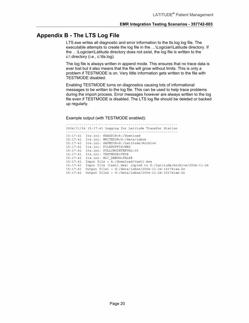
Appendix B - The LTS Log File LTS.exe writes all diagnostic and error information to the lts.log log file. The executable attempts to create the log file in the …\Logician\Latitude directory. If the …\Logician\Latitude directory does not exist, the log file is written to the c:\ directory (i.e., c:\lts.log).
The log file is always written in append mode. This ensures that no trace data is ever lost but it also means that the file will grow without limits. This is only a problem if TESTMODE is on. Very little information gets written to the file with TESTMODE disabled.
Enabling TESTMODE turns on diagnostics causing lots of informational messages to be written to the log file. This can be used to help trace problems during the import process. Error messages however are always written to the log file even if TESTMODE is disabled. The LTS log file should be deleted or backed up regularly.
Example output (with TESTMODE enabled): --------------------------------------------------------- 2004/11/24 15:17:41 Logging for Latitude Transfer Station --------------------------------------------------------- 15:17:41 lts.ini: READDIR=k:/Download 15:17:41 lts.ini: WRITEDIR=G:/data/inbox 15:17:41 lts.ini: SAVEDIR=D:/Latitude/Archive 15:17:41 lts.ini: FILESUFFIX=MES 15:17:41 lts.ini: POLLINGINTERVAL=30 15:17:41 lts.ini: TESTMODE=TRUE 15:17:41 lts.ini: HL7_DEBUG=FALSE 15:17:41 Input file = k:/download/test1.mes 15:17:41 Input file (test1.mes) copied to D:/Latitude/Archive/2004-11-24 15:17:41 Output file1 = G:/data/inbox/2004-11-24-151741aa.hr 15:17:41 Output file2 = G:/data/inbox/2004-11-24-151741ab.ht

EMR Integration Testing Scenarios - 357742-003
Page 21
LATITUDE® Patient Management
Appendix C – Example HL7 Message from LATITUDE
Before using this test message, the following changes must be considered. Failure to make proper changes will result in processing errors.
MSH-6 Clinic Name: Berry Street – This should be your clinic name.
PID-5 Patient Name: Sylvester Summers – must be an existing patient name in CPO.
PID-7 Patient Birth Date: 19480510 – must be the birth date of the “Patient Name”
PID-8 Patient Gender: M – must be the gender of the “Patient Name”
PV1-8-1 Physician Login: L602Farme – must either be the login ID of a valid CPO physician or must be properly mapped to a valid CPO physician.
ZU-1 Linkback URL: This URL will not work if this data is imported into the CPO system.
MSH|^~\&|LATITUDE|BOSTON SCIENTIFIC||Berry Street Clinic|20060925212610+0000||ORU^R01|2500001|P|2.3.1|||NE|||8859/1| PID|1|7943581896|7943581896||Summers^Sylvester^^||19480510|M|||^^^^39219||||||||| NTE|1|LATITUDE|\.br\My Alerts\.br\------------------------------\.br\18 Apr 2006-Atrial Tachycardia Response (ATR) for > 24 hours detected. Review episode detail in Arrhythmia Logbook within the Events tab.\.br\27 Dec 2005-Low atrial intrinsic amplitude detected. Schedule in-office follow-up to evaluate atrial pacing lead.\.br\24 Apr 2006-Shock therapy delivered to convert arrhythmia (Ventricular). Review episode detail in Arrhythmia Logbook within the Events tab. \.br\24 Apr 2006-Shock therapy delivered to convert arrhythmia (Ventricular). Review episode detail in Arrhythmia Logbook within the Events tab. \.br\21 Apr 2006-Atrial Tachycardia Response (ATR) for > 24 hours detected. Review episode detail in Arrhythmia Logbook within the Events tab.\.br\| NTE|2|LATITUDE|Dismissed from Review List in LATITUDE by Farmer, Luther (L602Farme) on 25 Sep 2006 at 15:26 CST| NTE|3|LATITUDE|\.br\Events Since Last Remote Follow-up(None)\.br\------------------------------\.br\| PV1|1|R|||||L602Farme^Farmer^Luther^^| OBR|1||2500759|BostonScientific-LastInterrogation^Last Interrogation|||20060428011327+0000|20060428011327+0000||||||||L602Farme||DR||||20060428011327+0000|||F| OBX|1|ST|GDT-00001^Result Source^GDT-LATITUDE||Remote Interrogation||||||F|| OBX|2|ST|GDT-00002^Device Manufacturer^GDT-LATITUDE||Boston Scientific||||||F|| OBX|3|ST|GDT-00003^Device Type^GDT-LATITUDE||CRT-D||||||F|| OBX|4|ST|GDT-00004^Device Name^GDT-LATITUDE||CONTAK||||||F|| OBX|5|ST|GDT-00005^Device Model Name^GDT-LATITUDE||RENEWAL 3 RF HE||||||F|| OBX|6|ST|GDT-00006^Device Model Number^GDT-LATITUDE||H219||||||F|| OBX|7|ST|GDT-00007^Device Serial Number^GDT-LATITUDE||542405||||||F|| OBX|8|DT|GDT-00108^Device Implant Date^GDT-LATITUDE||20040209||||||F|| OBX|9|NM|GDT-00008^Battery Gauge^GDT-LATITUDE||93|%|||||F|| OBX|10|ST|GDT-00009^Battery Status^GDT-LATITUDE||OK||||||F|| OBX|11|ST|GDT-00010^Monitoring Voltage^GDT-LATITUDE||3.16|V|||||F||

EMR Integration Testing Scenarios - 357742-003
Page 22
LATITUDE® Patient Management
OBX|12|NM|GDT-00011^Charge Time^GDT-LATITUDE||4.4|s|||||F|| OBX|13|DT|GDT-00012^Last Reform^GDT-LATITUDE||20060328||||||F|| OBX|14|ST|GDT-00097^Counters Since^GDT-LATITUDE||None||||||F|| OBX|15|ST|GDT-00013^VF Episodes^GDT-LATITUDE||||||||F|| OBX|16|ST|GDT-00014^VT Episodes^GDT-LATITUDE||||||||F|| OBX|17|ST|GDT-00015^VT-1 Episodes^GDT-LATITUDE||||||||F|| OBX|18|ST|GDT-00016^Non-Sustained Ventricular Episodes^GDT-LATITUDE||||||||F|| OBX|19|NM|GDT-00017^ATR Mode Switches^GDT-LATITUDE||||||||F|| OBX|20|NM|GDT-00020^Atrial Percent Paced^GDT-LATITUDE|||%|||||F|| OBX|21|NM|GDT-00021^RV Percent Paced^GDT-LATITUDE|||%|||||F|| OBX|22|NM|GDT-00022^LV Percent Paced^GDT-LATITUDE|||%|||||F|| OBX|23|ST|GDT-00023^Right Atrial Lead Status^GDT-LATITUDE||OK||||||F|| OBX|24|ST|GDT-00024^RA Intrinsic Amplitude^GDT-LATITUDE||Paced|mV|||||F|| OBX|25|ST|GDT-00025^RA Pace Impedance^GDT-LATITUDE||328|Ohms|||||F|| OBX|26|ST|GDT-00026^Right Ventricular Lead Status^GDT-LATITUDE||OK||||||F|| OBX|27|ST|GDT-00027^RV Intrinsic Amplitude^GDT-LATITUDE||Paced|mV|||||F|| OBX|28|ST|GDT-00028^RV Pace Impedance^GDT-LATITUDE||523|Ohms|||||F|| OBX|29|ST|GDT-00029^LV Lead Status^GDT-LATITUDE||OK||||||F|| OBX|30|ST|GDT-00030^LV Intrinsic Amplitude^GDT-LATITUDE||5.6|mV|||||F|| OBX|31|ST|GDT-00031^LV Pace Impedance^GDT-LATITUDE||440|Ohms|||||F|| OBX|32|ST|GDT-00032^Shock Vector Status^GDT-LATITUDE||OK||||||F|| OBX|33|ST|GDT-00033^Shock Impedance^GDT-LATITUDE||41|Ohms|||||F|| OBX|34|ST|GDT-00034^V-Tachy Mode^GDT-LATITUDE||Monitor + Therapy||||||F|| OBX|35|ST|GDT-00036^Brady Mode^GDT-LATITUDE||DDD||||||F|| OBX|36|NM|GDT-00037^Lower Rate Limit^GDT-LATITUDE||70|bpm|||||F|| OBX|37|NM|GDT-00038^Maximum Tracking Rate^GDT-LATITUDE||130|bpm|||||F|| OBX|38|NM|GDT-00039^Maximum Sensor Rate^GDT-LATITUDE||120|bpm|||||F|| OBX|39|ST|GDT-00040^Sensitivity RA^GDT-LATITUDE||Nominal||||||F|| OBX|40|ST|GDT-00041^Sensitivity RV^GDT-LATITUDE||Nominal||||||F|| OBX|41|ST|GDT-00042^Sensitivity LV^GDT-LATITUDE||Nominal||||||F|| OBX|42|ST|GDT-00043^Paced AV Delay^GDT-LATITUDE||120|ms|||||F|| OBX|43|ST|GDT-00044^Sensed AV Offset^GDT-LATITUDE||Off|ms|||||F|| OBX|44|ST|GDT-00047^A-Refractory (PVARP)^GDT-LATITUDE||240 - 250|ms|||||F|| OBX|45|ST|GDT-00048^RV-Refractory (RVRP)^GDT-LATITUDE||240 - 250|ms|||||F|| OBX|46|NM|GDT-00049^LV-Refractory (LVRP)^GDT-LATITUDE||250|ms|||||F|| OBX|47|NM|GDT-00050^LV Protection Period^GDT-LATITUDE||400|ms|||||F|| OBX|48|ST|GDT-00051^Ventricular Pacing Chamber^GDT-LATITUDE||BiV||||||F|| OBX|49|NM|GDT-00052^Ventricular Pacing Chamber LV Offset^GDT-LATITUDE||0|ms|||||F|| OBX|50|ST|GDT-00053^Pacing Output - RA^GDT-LATITUDE||2.4 V @ 0.5 ms||||||F|| OBX|51|ST|GDT-00054^Pacing Output - RV^GDT-LATITUDE||2.4 V @ 0.5 ms||||||F|| OBX|52|ST|GDT-00055^Pacing Output - LV^GDT-LATITUDE||6.0 V @ 1.0 ms||||||F|| OBX|53|ST|GDT-00056^ATR Mode Switch Mode^GDT-LATITUDE||VDIR||||||F|| OBX|54|ST|GDT-00057^ATR Mode Switch Rate^GDT-LATITUDE||170|bpm|||||F|| OBX|55|NM|GDT-00074^VF Zone^GDT-LATITUDE||200|bpm|||||F|| OBX|56|NM|GDT-00075^VF Shock 1 Energy^GDT-LATITUDE||41|J|||||F|| OBX|57|NM|GDT-00076^VF Shock 2 Energy^GDT-LATITUDE||41|J|||||F|| OBX|58|NM|GDT-00077^VF Max Shock Energy^GDT-LATITUDE||41|J|||||F|| OBX|59|NM|GDT-00078^VF Number Of Additional Shocks^GDT-LATITUDE||6||||||F||

EMR Integration Testing Scenarios - 357742-003
Page 23
LATITUDE® Patient Management
OBX|60|NM|GDT-00079^VT Zone^GDT-LATITUDE||180|bpm|||||F|| OBX|61|ST|GDT-00080^VT Zone ATP1 Type^GDT-LATITUDE||Scan||||||F|| OBX|62|ST|GDT-00081^VT Zone ATP1 Number of Bursts^GDT-LATITUDE||4||||||F|| OBX|63|ST|GDT-00082^VT Zone ATP2 Type^GDT-LATITUDE||Disabled||||||F|| OBX|64|ST|GDT-00083^VT Zone ATP2 Number of Bursts^GDT-LATITUDE||Off||||||F|| OBX|65|ST|GDT-00084^VT Shock 1 Energy^GDT-LATITUDE||26|J|||||F|| OBX|66|ST|GDT-00085^VT Shock 2 Energy^GDT-LATITUDE||41|J|||||F|| OBX|67|ST|GDT-00086^VT Max Shock Energy^GDT-LATITUDE||41|J|||||F|| OBX|68|NM|GDT-00087^VT Number Of Additional Max Energy Shocks^GDT-LATITUDE||3||||||F|| OBR|2||2500759|BostonScientific-Implant^Implant|||20040209|20040209||||||||L602Farme||DR||||20040209|||F| OBX|1|ST|GDT-00001^Result Source^GDT-LATITUDE||Implant||||||F|| OBX|2|ST|GDT-00002^Device Manufacturer^GDT-LATITUDE||Boston Scientific||||||F|| OBX|3|ST|GDT-00003^Device Type^GDT-LATITUDE||CRT-D||||||F|| OBX|4|ST|GDT-00004^Device Name^GDT-LATITUDE||CONTAK||||||F|| OBX|5|ST|GDT-00005^Device Model Name^GDT-LATITUDE||RENEWAL 3 RF HE||||||F|| OBX|6|ST|GDT-00006^Device Model Number^GDT-LATITUDE||H219||||||F|| OBX|7|ST|GDT-00007^Device Serial Number^GDT-LATITUDE||542405||||||F|| OBX|8|DT|GDT-00108^Device Implant Date^GDT-LATITUDE||20040209||||||F|| OBX|9|ST|GDT-00098^RA Intrinsic Amplitude^GDT-LATITUDE|||mV|||||F|| OBX|10|ST|GDT-00099^RA Pace Impedance^GDT-LATITUDE|||Ohms|||||F|| OBX|11|ST|GDT-00100^RA Pace Threshold^GDT-LATITUDE||V @ ms||||||F|| OBX|12|ST|GDT-00101^RV Intrinsic Amplitude^GDT-LATITUDE|||mV|||||F|| OBX|13|ST|GDT-00102^RV Pace Impedance^GDT-LATITUDE|||Ohms|||||F|| OBX|14|ST|GDT-00103^RV Pace Threshold^GDT-LATITUDE||V @ ms||||||F|| OBX|15|ST|GDT-00104^LV Intrinsic Amplitude^GDT-LATITUDE|||mV|||||F|| OBX|16|ST|GDT-00105^LV Pace Impedance^GDT-LATITUDE|||Ohms|||||F|| OBX|17|ST|GDT-00106^LV Pace Threshold^GDT-LATITUDE||V @ ms||||||F|| OBX|18|ST|GDT-00107^Shock Impedance^GDT-LATITUDE|||Ohms|||||F|| OBR|3||2500759|BostonScientific-LastInOffice^Last In-Office Lead Test|||20060424|20060424||||||||L602Farme||DR||||20060424|||F| OBX|1|ST|GDT-00001^Result Source^GDT-LATITUDE||In-Office Lead Test||||||F|| OBX|2|ST|GDT-00002^Device Manufacturer^GDT-LATITUDE||Boston Scientific||||||F|| OBX|3|ST|GDT-00003^Device Type^GDT-LATITUDE||CRT-D||||||F|| OBX|4|ST|GDT-00004^Device Name^GDT-LATITUDE||CONTAK||||||F|| OBX|5|ST|GDT-00005^Device Model Name^GDT-LATITUDE||RENEWAL 3 RF HE||||||F|| OBX|6|ST|GDT-00006^Device Model Number^GDT-LATITUDE||H219||||||F|| OBX|7|ST|GDT-00007^Device Serial Number^GDT-LATITUDE||542405||||||F|| OBX|8|DT|GDT-00108^Device Implant Date^GDT-LATITUDE||20040209||||||F|| OBX|9|ST|GDT-00109^RA Intrinsic Amplitude^GDT-LATITUDE||Paced|mV|||||F|||| OBX|10|ST|GDT-00110^RA Pace Impedance^GDT-LATITUDE||330|Ohms|||||F|||| OBX|11|ST|GDT-00111^RA Pace Threshold^GDT-LATITUDE||0.6 V @ 0.5 ms||||||F|||| OBX|12|ST|GDT-00112^RV Intrinsic Amplitude^GDT-LATITUDE||Paced|mV|||||F|||| OBX|13|ST|GDT-00113^RV Pace Impedance^GDT-LATITUDE||523|Ohms|||||F|||| OBX|14|ST|GDT-00114^RV Pace Threshold^GDT-LATITUDE||0.6 V @ 0.5 ms||||||F|||| OBX|15|ST|GDT-00115^LV Intrinsic Amplitude^GDT-LATITUDE||5.8|mV|||||F|||| OBX|16|ST|GDT-00116^LV Pace Impedance^GDT-LATITUDE||422|Ohms|||||F||||

EMR Integration Testing Scenarios - 357742-003
Page 24
LATITUDE® Patient Management
OBX|17|ST|GDT-00117^LV Pace Threshold^GDT-LATITUDE||3.5 V @ 1.0 ms||||||F|||| OBX|18|ST|GDT-00118^Shock Impedance^GDT-LATITUDE||38|Ohms|||||F|||| OBR|4||2500759|BostonScientific-Leads^Lead Information|||20060925212609+0000|20060925212609+0000||||||||L602Farme||DR||||20060925212609+0000|||F| ZU1|https://www.test.bostonscientific.com:443/access/physician/patientDetails| ZU2|Device Summary Report Version 1|

EMR Integration Testing Scenarios - 357742-003
Page 25
LATITUDE® Patient Management
Appendix D – Example .HR Message from LTS
Before using this test message, the changes listed in Appendix C must be considered. Failure to make proper changes will result in processing errors.
MSH|^~\&|LATITUDE|BOSTON SCIENTIFIC||Berry Street Clinic|20060925162610||ORU|2500001|P|2.3|||NE|||8859/1| PID|1|7943581896|7943581896||Summers^Sylvester^^||19480510|M|||^^^^39219||||||||| NTE|1|LATITUDE|\.br\My Alerts\.br\------------------------------\.br\18 Apr 2006-Atrial Tachycardia Response (ATR) for > 24 hours detected. Review episode detail in Arrhythmia Logbook within the Events tab.\.br\27 Dec 2005-Low atrial intrinsic amplitude detected. Schedule in-office follow-up to evaluate atrial pacing lead.\.br\24 Apr 2006-Shock therapy delivered to convert arrhythmia (Ventricular). Review episode detail in Arrhythmia Logbook within the Events tab. \.br\24 Apr 2006-Shock therapy delivered to convert arrhythmia (Ventricular). Review episode detail in Arrhythmia Logbook within the Events tab. \.br\21 Apr 2006-Atrial Tachycardia Response (ATR) for > 24 hours detected. Review episode detail in Arrhythmia Logbook within the Events tab.\.br\| NTE|2|LATITUDE|Dismissed from Review List in LATITUDE by Farmer, Luther (L602Farme) on 25 Sep 2006 at 15:26 CST| NTE|3|LATITUDE|\.br\Events Since Last Remote Follow-up(None)\.br\------------------------------\.br\| PV1|1|R|||||L602Farme^Farmer^Luther^^| OBR|1||2500759|BostonScientific-LastInterrogation^Last Interrogation|||20060427201327|20060427201327||||||||L602Farme||GDT Intrgn|200609251659160961|||20060427201327|||F| OBX|1|ST|GDT-00001^Result Source^GDT-LATITUDE||Remote Interrogation||||||F|| OBX|2|ST|GDT-00002^Device Manufacturer^GDT-LATITUDE||Boston Scientific||||||F|| OBX|3|ST|GDT-00003^Device Type^GDT-LATITUDE||CRT-D||||||F|| OBX|4|ST|GDT-00004^Device Name^GDT-LATITUDE||CONTAK||||||F|| OBX|5|ST|GDT-00005^Device Model Name^GDT-LATITUDE||RENEWAL 3 RF HE||||||F|| OBX|6|ST|GDT-00006^Device Model Number^GDT-LATITUDE||H219||||||F|| OBX|7|ST|GDT-00007^Device Serial Number^GDT-LATITUDE||542405||||||F|| OBX|8|ST|GDT-00108^Device Implant Date^GDT-LATITUDE||09 Feb 2004||||||F|| OBX|9|NM|GDT-00008^Battery Gauge^GDT-LATITUDE||93|%|||||F|| OBX|10|ST|GDT-00009^Battery Status^GDT-LATITUDE||OK||||||F|| OBX|11|ST|GDT-00010^Monitoring Voltage^GDT-LATITUDE||3.16|V|||||F|| OBX|12|NM|GDT-00011^Charge Time^GDT-LATITUDE||4.4|s|||||F|| OBX|13|ST|GDT-00012^Last Reform^GDT-LATITUDE||28 Mar 2006||||||F|| OBX|14|ST|GDT-00097^Counters Since^GDT-LATITUDE||None||||||F|| OBX|15|ST|GDT-00013^VF Episodes^GDT-LATITUDE||DNR||||||F|| OBX|16|ST|GDT-00014^VT Episodes^GDT-LATITUDE||DNR||||||F|| OBX|17|ST|GDT-00015^VT-1 Episodes^GDT-LATITUDE||DNR||||||F||

EMR Integration Testing Scenarios - 357742-003
Page 26
LATITUDE® Patient Management
OBX|18|ST|GDT-00016^Non-Sustained Ventricular Episodes^GDT-LATITUDE||DNR||||||F|| OBX|19|NM|GDT-00017^ATR Mode Switches^GDT-LATITUDE||DNR||||||F|| OBX|20|NM|GDT-00020^Atrial Percent Paced^GDT-LATITUDE||DNR|%|||||F|| OBX|21|NM|GDT-00021^RV Percent Paced^GDT-LATITUDE||DNR|%|||||F|| OBX|22|NM|GDT-00022^LV Percent Paced^GDT-LATITUDE||DNR|%|||||F|| OBX|23|ST|GDT-00023^Right Atrial Lead Status^GDT-LATITUDE||OK||||||F|| OBX|24|ST|GDT-00024^RA Intrinsic Amplitude^GDT-LATITUDE||Paced|mV|||||F|| OBX|25|ST|GDT-00025^RA Pace Impedance^GDT-LATITUDE||328|Ohms|||||F|| OBX|26|ST|GDT-00026^Right Ventricular Lead Status^GDT-LATITUDE||OK||||||F|| OBX|27|ST|GDT-00027^RV Intrinsic Amplitude^GDT-LATITUDE||Paced|mV|||||F|| OBX|28|ST|GDT-00028^RV Pace Impedance^GDT-LATITUDE||523|Ohms|||||F|| OBX|29|ST|GDT-00029^LV Lead Status^GDT-LATITUDE||OK||||||F|| OBX|30|ST|GDT-00030^LV Intrinsic Amplitude^GDT-LATITUDE||5.6|mV|||||F|| OBX|31|ST|GDT-00031^LV Pace Impedance^GDT-LATITUDE||440|Ohms|||||F|| OBX|32|ST|GDT-00032^Shock Vector Status^GDT-LATITUDE||OK||||||F|| OBX|33|ST|GDT-00033^Shock Impedance^GDT-LATITUDE||41|Ohms|||||F|| OBX|34|ST|GDT-00034^V-Tachy Mode^GDT-LATITUDE||Monitor + Therapy||||||F|| OBX|35|ST|GDT-00036^Brady Mode^GDT-LATITUDE||DDD||||||F|| OBX|36|NM|GDT-00037^Lower Rate Limit^GDT-LATITUDE||70|bpm|||||F|| OBX|37|NM|GDT-00038^Maximum Tracking Rate^GDT-LATITUDE||130|bpm|||||F|| OBX|38|NM|GDT-00039^Maximum Sensor Rate^GDT-LATITUDE||120|bpm|||||F|| OBX|39|ST|GDT-00040^Sensitivity RA^GDT-LATITUDE||Nominal||||||F|| OBX|40|ST|GDT-00041^Sensitivity RV^GDT-LATITUDE||Nominal||||||F|| OBX|41|ST|GDT-00042^Sensitivity LV^GDT-LATITUDE||Nominal||||||F|| OBX|42|ST|GDT-00043^Paced AV Delay^GDT-LATITUDE||120|ms|||||F|| OBX|43|ST|GDT-00044^Sensed AV Offset^GDT-LATITUDE||Off|ms|||||F|| OBX|44|ST|GDT-00047^A-Refractory (PVARP)^GDT-LATITUDE||240 - 250|ms|||||F|| OBX|45|ST|GDT-00048^RV-Refractory (RVRP)^GDT-LATITUDE||240 - 250|ms|||||F|| OBX|46|NM|GDT-00049^LV-Refractory (LVRP)^GDT-LATITUDE||250|ms|||||F|| OBX|47|NM|GDT-00050^LV Protection Period^GDT-LATITUDE||400|ms|||||F|| OBX|48|ST|GDT-00051^Ventricular Pacing Chamber^GDT-LATITUDE||BiV||||||F|| OBX|49|NM|GDT-00052^Ventricular Pacing Chamber LV Offset^GDT-LATITUDE||0|ms|||||F|| OBX|50|ST|GDT-00053^Pacing Output - RA^GDT-LATITUDE||2.4 V @ 0.5 ms||||||F|| OBX|51|ST|GDT-00054^Pacing Output - RV^GDT-LATITUDE||2.4 V @ 0.5 ms||||||F|| OBX|52|ST|GDT-00055^Pacing Output - LV^GDT-LATITUDE||6.0 V @ 1.0 ms||||||F|| OBX|53|ST|GDT-00056^ATR Mode Switch Mode^GDT-LATITUDE||VDIR||||||F|| OBX|54|ST|GDT-00057^ATR Mode Switch Rate^GDT-LATITUDE||170|bpm|||||F|| OBX|55|NM|GDT-00074^VF Zone^GDT-LATITUDE||200|bpm|||||F|| OBX|56|NM|GDT-00075^VF Shock 1 Energy^GDT-LATITUDE||41|joules|||||F|| OBX|57|NM|GDT-00076^VF Shock 2 Energy^GDT-LATITUDE||41|joules|||||F|| OBX|58|NM|GDT-00077^VF Max Shock Energy^GDT-LATITUDE||41|joules|||||F|| OBX|59|NM|GDT-00078^VF Number Of Additional Shocks^GDT-LATITUDE||6||||||F|| OBX|60|NM|GDT-00079^VT Zone^GDT-LATITUDE||180|bpm|||||F|| OBX|61|ST|GDT-00080^VT Zone ATP1 Type^GDT-LATITUDE||Scan||||||F||

EMR Integration Testing Scenarios - 357742-003
Page 27
LATITUDE® Patient Management
OBX|62|ST|GDT-00081^VT Zone ATP1 Number of Bursts^GDT-LATITUDE||4||||||F|| OBX|63|ST|GDT-00082^VT Zone ATP2 Type^GDT-LATITUDE||Disabled||||||F|| OBX|64|ST|GDT-00083^VT Zone ATP2 Number of Bursts^GDT-LATITUDE||Off||||||F|| OBX|65|ST|GDT-00084^VT Shock 1 Energy^GDT-LATITUDE||26|joules|||||F|| OBX|66|ST|GDT-00085^VT Shock 2 Energy^GDT-LATITUDE||41|joules|||||F|| OBX|67|ST|GDT-00086^VT Max Shock Energy^GDT-LATITUDE||41|joules|||||F|| OBX|68|NM|GDT-00087^VT Number Of Additional Max Energy Shocks^GDT-LATITUDE||3||||||F|| OBR|2||2500759|BostonScientific-Implant^Implant|||20040209|20040209||||||||L602Farme||GDT Intrgn|200609251659160961|||20040209|||F| OBX|1|ST|GDT-00001^Result Source^GDT-LATITUDE||Implant||||||F|| OBX|2|ST|GDT-00002^Device Manufacturer^GDT-LATITUDE||Boston Scientific||||||F|| OBX|3|ST|GDT-00003^Device Type^GDT-LATITUDE||CRT-D||||||F|| OBX|4|ST|GDT-00004^Device Name^GDT-LATITUDE||CONTAK||||||F|| OBX|5|ST|GDT-00005^Device Model Name^GDT-LATITUDE||RENEWAL 3 RF HE||||||F|| OBX|6|ST|GDT-00006^Device Model Number^GDT-LATITUDE||H219||||||F|| OBX|7|ST|GDT-00007^Device Serial Number^GDT-LATITUDE||542405||||||F|| OBX|8|ST|GDT-00108^Device Implant Date^GDT-LATITUDE||09 Feb 2004||||||F|| OBX|9|ST|GDT-00098^RA Intrinsic Amplitude^GDT-LATITUDE||DNR|mV|||||F|| OBX|10|ST|GDT-00099^RA Pace Impedance^GDT-LATITUDE||DNR|Ohms|||||F|| OBX|11|ST|GDT-00100^RA Pace Threshold^GDT-LATITUDE||V @ ms||||||F|| OBX|12|ST|GDT-00101^RV Intrinsic Amplitude^GDT-LATITUDE||DNR|mV|||||F|| OBX|13|ST|GDT-00102^RV Pace Impedance^GDT-LATITUDE||DNR|Ohms|||||F|| OBX|14|ST|GDT-00103^RV Pace Threshold^GDT-LATITUDE||V @ ms||||||F|| OBX|15|ST|GDT-00104^LV Intrinsic Amplitude^GDT-LATITUDE||DNR|mV|||||F|| OBX|16|ST|GDT-00105^LV Pace Impedance^GDT-LATITUDE||DNR|Ohms|||||F|| OBX|17|ST|GDT-00106^LV Pace Threshold^GDT-LATITUDE||V @ ms||||||F|| OBX|18|ST|GDT-00107^Shock Impedance^GDT-LATITUDE||DNR|Ohms|||||F|| OBR|3||2500759|BostonScientific-LastInOffice^Last In-Office Lead Test|||20060424|20060424||||||||L602Farme||GDT Intrgn|200609251659160961|||20060424|||F| OBX|1|ST|GDT-00001^Result Source^GDT-LATITUDE||In-Office Lead Test||||||F|| OBX|2|ST|GDT-00002^Device Manufacturer^GDT-LATITUDE||Boston Scientific||||||F|| OBX|3|ST|GDT-00003^Device Type^GDT-LATITUDE||CRT-D||||||F|| OBX|4|ST|GDT-00004^Device Name^GDT-LATITUDE||CONTAK||||||F|| OBX|5|ST|GDT-00005^Device Model Name^GDT-LATITUDE||RENEWAL 3 RF HE||||||F|| OBX|6|ST|GDT-00006^Device Model Number^GDT-LATITUDE||H219||||||F|| OBX|7|ST|GDT-00007^Device Serial Number^GDT-LATITUDE||542405||||||F|| OBX|8|ST|GDT-00108^Device Implant Date^GDT-LATITUDE||09 Feb 2004||||||F|| OBX|9|ST|GDT-00109^RA Intrinsic Amplitude^GDT-LATITUDE||Paced|mV|||||F|||| OBX|10|ST|GDT-00110^RA Pace Impedance^GDT-LATITUDE||330|Ohms|||||F|||| OBX|11|ST|GDT-00111^RA Pace Threshold^GDT-LATITUDE||0.6 V @ 0.5 ms||||||F|||| OBX|12|ST|GDT-00112^RV Intrinsic Amplitude^GDT-LATITUDE||Paced|mV|||||F|||| OBX|13|ST|GDT-00113^RV Pace Impedance^GDT-LATITUDE||523|Ohms|||||F||||

EMR Integration Testing Scenarios - 357742-003
Page 28
LATITUDE® Patient Management
OBX|14|ST|GDT-00114^RV Pace Threshold^GDT-LATITUDE||0.6 V @ 0.5 ms||||||F|||| OBX|15|ST|GDT-00115^LV Intrinsic Amplitude^GDT-LATITUDE||5.8|mV|||||F|||| OBX|16|ST|GDT-00116^LV Pace Impedance^GDT-LATITUDE||422|Ohms|||||F|||| OBX|17|ST|GDT-00117^LV Pace Threshold^GDT-LATITUDE||3.5 V @ 1.0 ms||||||F|||| OBX|18|ST|GDT-00118^Shock Impedance^GDT-LATITUDE||38|Ohms|||||F|||| OBR|4||2500759|BostonScientific-Leads^Lead Information|||20060925162609|20060925162609||||||||L602Farme||GDT Intrgn|200609251659160961|||20060925162609|||F| OBX|1|ST|MLI-93615^LatitudeURL^GDT-LATITUDE|| https://www.test.bostonscientific.com:443/access/physician/patientDetails||||||F||||

EMR Integration Testing Scenarios - 357742-003
Page 29
LATITUDE® Patient Management
Appendix E – Example .HT Message from LTS
Before using this test message, the changes listed in Appendix C must be considered. Failure to make proper changes will result in processing errors.
MSH|^~\&|LATITUDE|BOSTON SCIENTIFIC||Berry Street Clinic|20060925162610||MDM|2500001|P|2.3|||NE|||8859/1| EVN|T02|20060925162610|||| PID|1|7943581896|7943581896||Summers^Sylvester^^||19480510|M|||^^^^39219||||||||| PV1|1|R|||||L602Farme^Farmer^Luther^^| TXA|1|DR|TX|||||||||||||200609251659160961|DO|||||| OBX|1|TX|IMAGE_REF|| https://www.test.bostonscientific.com:443/access/physician/patientDetails^Device Summary Report Version 1||||||||||

EMR Integration Testing Scenarios - 357742-003
Page 30
LATITUDE® Patient Management
Boston Scientific 4100 Hamline Avenue North St. Paul, MN 55112-5798 USA Telephone: 651.582.4000 Medical Professionals: 1.800.CARDIAC (227.3422) Patients and Families: 1.866.484.3268
www.bostonscientific.com
© 2008 Boston Scientific or its affiliates. All rights reserved. 357742-003 EN US 05/08
*357742-003*