overview of condition based maintenance - logistics · pdf file · 2014-10-281...
TRANSCRIPT

1
Overview of
Condition Based Maintenance
Presented By:
Jeff Banks
Research Engineer
The Applied Research Laboratory at
The Pennsylvania State University

2
RCM and CBM
• Reliability Centered Maintenance (RCM): A process to determine
the optimum combination of maintenance types for any application
or system.
– One of the maintenance types is CBM.
• Condition Based Maintenance (CBM): A maintenance
methodology that utilizes sensors to assess the health of the
system. The health information drives the maintenance activities.
– In a CBM environment, operating platforms, embedded sensors,
inspections, and other triggering events determine when
restorative maintenance tasks are required based on evidence
of need.
– Predictive Maintenance (PdM) is a term widely used in industry
that is synonymous with CBM.
3
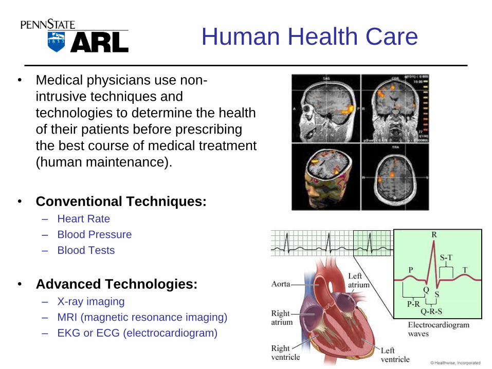
Human Health Care
• Medical physicians use non-
intrusive techniques and
technologies to determine the health
of their patients before prescribing
the best course of medical treatment
(human maintenance).
• Conventional Techniques:
– Heart Rate
– Blood Pressure
– Blood Tests
• Advanced Technologies:
– X-ray imaging
– MRI (magnetic resonance imaging)
– EKG or ECG (electrocardiogram)
3

4
Terminology
• Diagnostic Capability: the ability to detect and isolate a failure to a
specific platform component or system.
• Predictive Capability: the ability to detect and isolate a fault to a specific
platform component or system while the system is still functional.
• Prognostic Capability: the ability to detect and isolate a fault to a
specific platform component or system while the system is still functional
and the ability to determine the remaining useful life (RUL) until failure.

5
Condition Based
Maintenance1. Condition measurement consists of non-invasive data and
information collection events that define the systems operating condition.
– Measurements may be made continuously on-platform from installed transducers and sensors.
– Or periodically at-platform with portable data acquisition systems with transducers and sensors.
2. Condition monitoring and (health) assessment is the individual and collective comparison of condition measurements, value versus time trends to arrive at an appraisal of current condition, identify and analyze defects (diagnostic), project estimated future condition (predictive) and determine remaining useful life (prognostics).
– Condition assessment is also directed at detecting and identifying degradation mechanisms (root cause of failure).
3. Repair and Maintenance actions based on condition monitoring and health assessment — the objective evidence of need.
Reference: OPERATING EQUIPMENT ASSET MANAGEMENT YOUR 21ST CENTURY COMPETITIVE NECESSITY, By John S. Mitchell

6
CBM: Expectations
CBM can provide:• Warn of many mechanical problems in time to minimize:
– unexpected failure
– the risk and consequences of collateral damage
– adverse impact on safety, operations, and the environment
• Increase equipment utilization and life:
– minimize disruption to mission and schedule
• Reduce maintenance costs – both parts and labor:
– reduce requirements for spare parts
• Allow safe elimination of a significant amount of PM:
– predictive maintenance should be less time and labor intensive
CBM can not provide:• Elimination of defects and problems, or stop machines from
deteriorating.
– material wear is an accepted consequence of running equipment
7
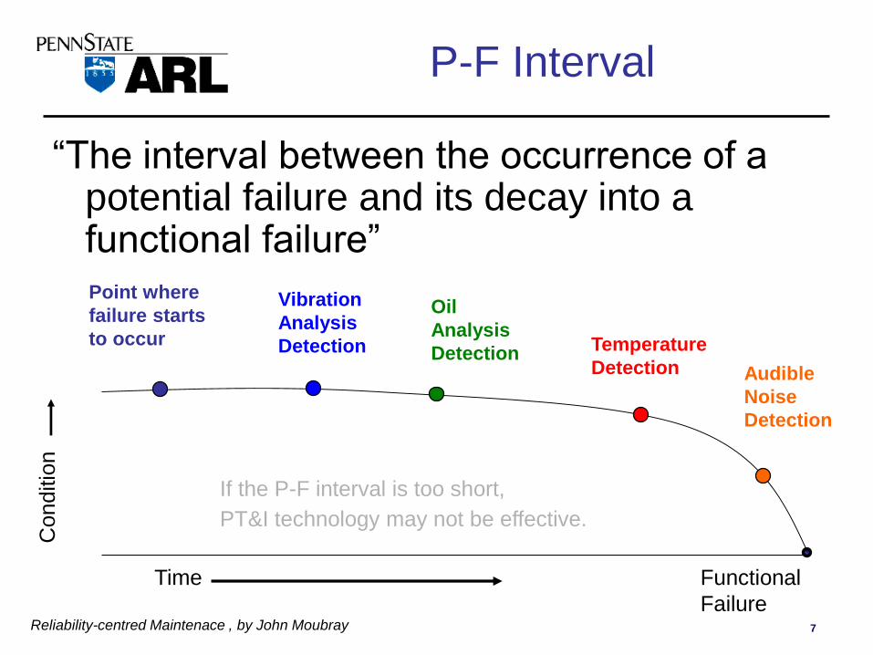
P-F Interval
“The interval between the occurrence of a potential failure and its decay into a functional failure”
Reliability-centred Maintenace , by John Moubray
Point where
failure starts
to occur
Vibration
Analysis
Detection
Oil
Analysis
DetectionAudible
Noise
Detection
Temperature
Detection
Conditio
n
Time Functional
Failure
If the P-F interval is too short,
PT&I technology may not be effective.

8
Criteria for Applying CBM
Preliminary Questions:
1. Does the technology monitor a specific critical failure mode? RCM FMECA
2. Is it probable that this failure mode will occur during the lifetime of the equipment? RCM Criticality
Application Criteria:• Changes in specific equipment parameters
(i.e. operating performance, temperature, vibration) must correlate to corresponding failure mode.
• The parameter must be accurately and consistently measurable.
• There must be enough time between potential and functional failure to allow for corrective action.
• The monitoring interval must be shorter then the P-F interval.
– Multiple monitoring points during the P-F interval increases confidence in the diagnosis.
Applying RCM Principles in the Selection of CBM-Enabling Technologies, L&FP November 2000, Kenneth S. Jacobs
9
9
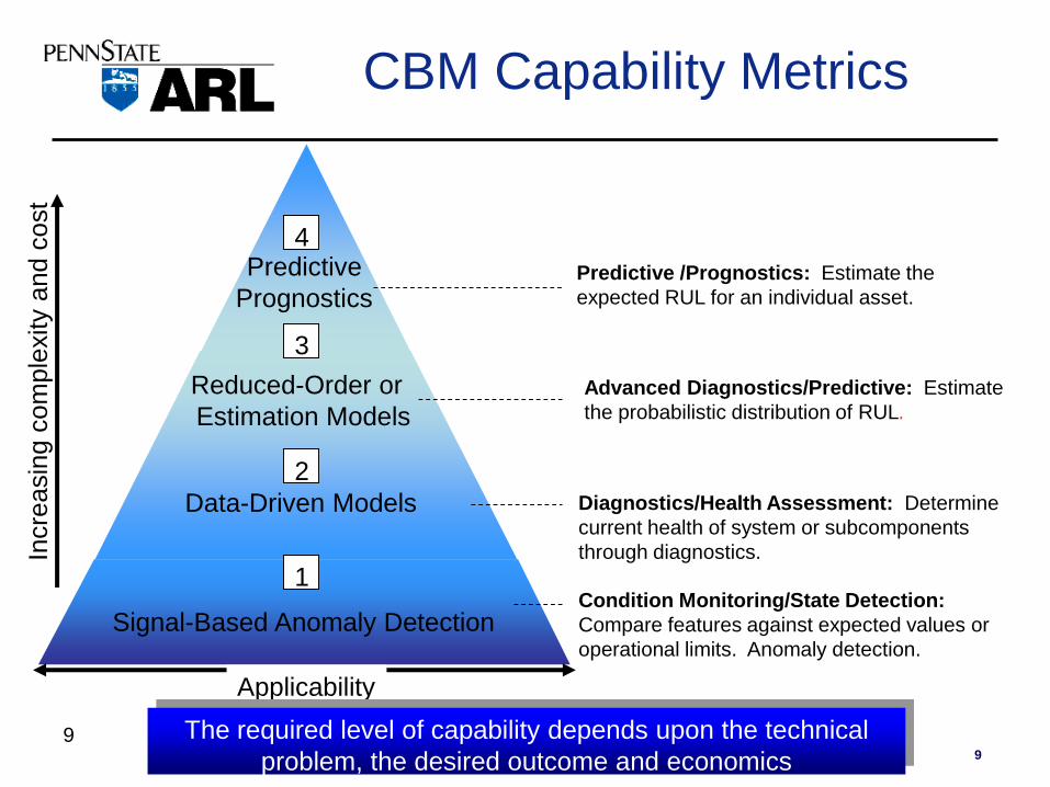
CBM Capability Metrics
Advanced Diagnostics/Predictive: Estimate
the probabilistic distribution of RUL.
Predictive /Prognostics: Estimate the
expected RUL for an individual asset.
Diagnostics/Health Assessment: Determine
current health of system or subcomponents
through diagnostics.
Condition Monitoring/State Detection:
Compare features against expected values or
operational limits. Anomaly detection.
Reduced-Order or
Estimation Models
Applicability
Signal-Based Anomaly Detection
Data-Driven Models
Incre
asin
g c
om
ple
xity a
nd c
ost
Predictive
Prognostics
1
2
3
4
The required level of capability depends upon the technical
problem, the desired outcome and economics

10
Aircraft Inspection
• Nondestructive testing is used extensively during the manufacturing of aircraft.
• NDT is also used to find cracks and corrosion damage during operation of the aircraft.
• A fatigue crack that started at the site of a lightning strike is shown below.
11
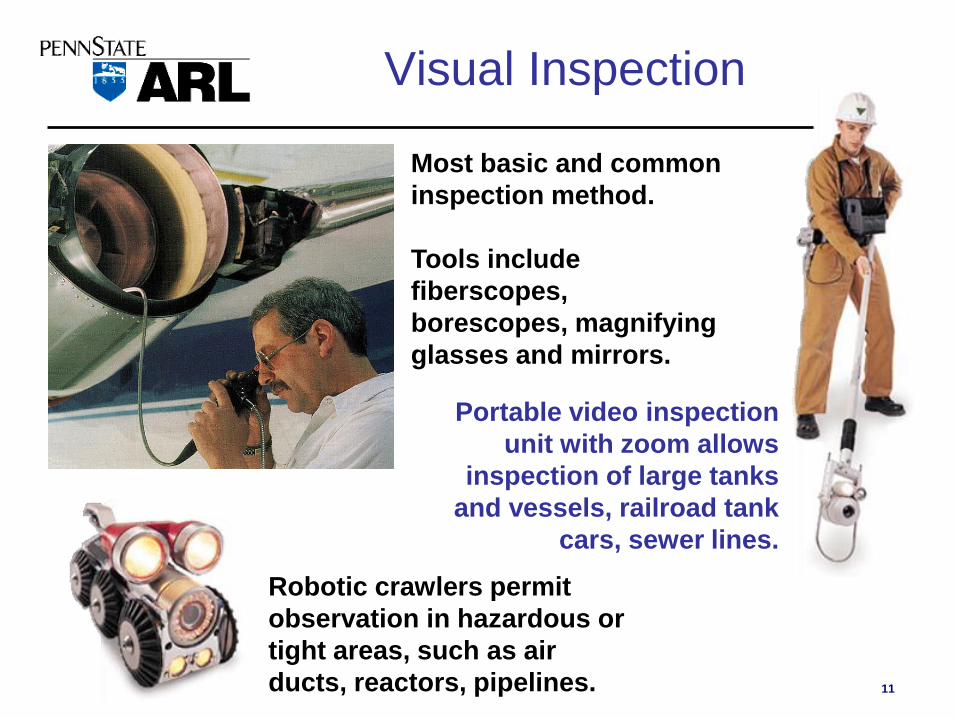
Most basic and common
inspection method.
Tools include
fiberscopes,
borescopes, magnifying
glasses and mirrors.
Robotic crawlers permit
observation in hazardous or
tight areas, such as air
ducts, reactors, pipelines.
Portable video inspection
unit with zoom allows
inspection of large tanks
and vessels, railroad tank
cars, sewer lines.
Visual Inspection

12
• A liquid with high surface wetting characteristics is applied to
the surface of the part and allowed time to seep into surface
defects.
• The excess liquid is removed from the surface of the part.
• A developer (powder) is applied to pull the trapped
penetrant out of the defect and spread it on the surface,
where it can be seen.
• Visual inspection is the final step in the process. The
penetrant used is often loaded with a fluorescent dye
and the inspection is done under UV light to increase
test sensitivity.
Liquid Penetrant Inspection

13
Eddy Current Testing
• Eddy current inspection is one of several NDT methods that use the principal of “electromagnetism” as the basis for conducting examinations.
• Eddy currents are created through a process called electromagnetic induction.– When alternating current is applied to the conductor, such as copper wire, a magnetic field develops in and around
the conductor.
• If another electrical conductor is brought into the close proximity to this changing magnetic field, current will be induced in this second conductor.
• Eddy currents are induced electrical currents that flow in a circular path.
– They get their name from “eddies” that are formed when a liquid or gas flows in a circular path around obstacles when conditions are right.
ConductiveMaterial
Coil'sMagnetic Field
Eddy
Currents
Eddy Current'sMagnetic Field
AC
Source
Volt
Meter
14
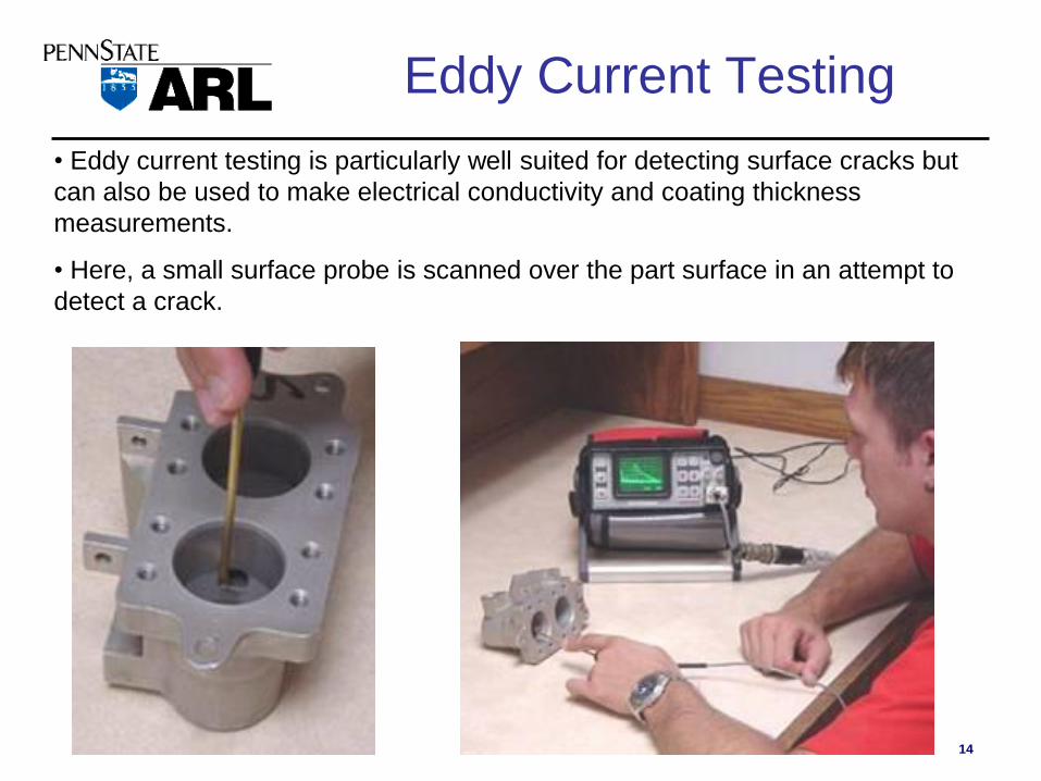
Eddy Current Testing
• Eddy current testing is particularly well suited for detecting surface cracks but
can also be used to make electrical conductivity and coating thickness
measurements.
• Here, a small surface probe is scanned over the part surface in an attempt to
detect a crack.

16
Acoustic Emission (AE)
• The ‘stress’ wave provides diagnostic information about the system being evaluated.
• This NDE technique is used widely for the testing of pressure vessels and load be.
17
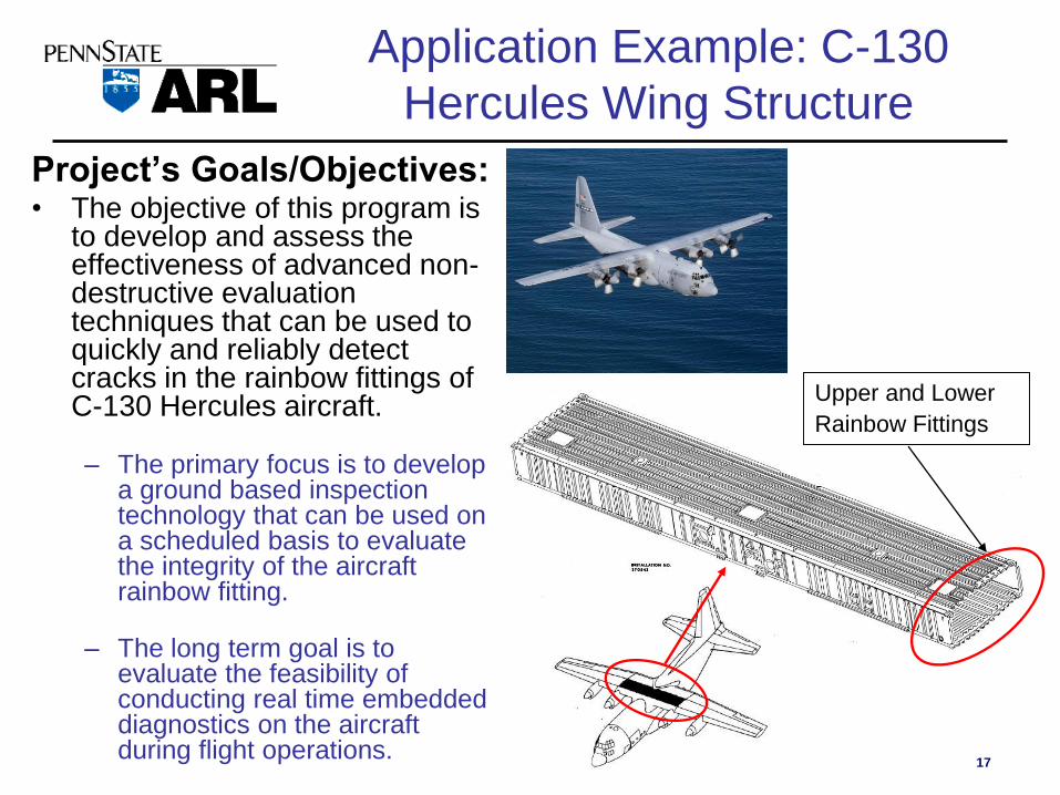
Application Example: C-130
Hercules Wing Structure
Project’s Goals/Objectives:• The objective of this program is
to develop and assess the effectiveness of advanced non-destructive evaluation techniques that can be used to quickly and reliably detect cracks in the rainbow fittings of C-130 Hercules aircraft.
– The primary focus is to develop a ground based inspection technology that can be used on a scheduled basis to evaluate the integrity of the aircraft rainbow fitting.
– The long term goal is to evaluate the feasibility of conducting real time embedded diagnostics on the aircraft during flight operations.
Upper and Lower
Rainbow Fittings
18
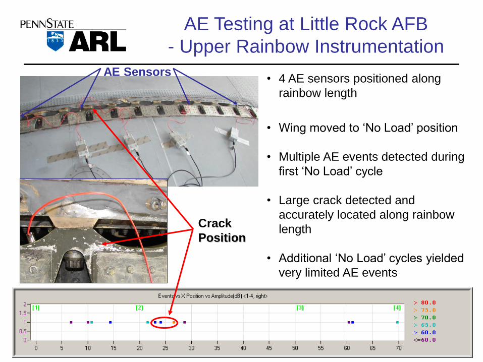
AE Testing at Little Rock AFB
- Upper Rainbow Instrumentation
• 4 AE sensors positioned along
rainbow length
• Wing moved to ‘No Load’ position
• Multiple AE events detected during
first ‘No Load’ cycle
• Large crack detected and
accurately located along rainbow
length
• Additional ‘No Load’ cycles yielded
very limited AE events
AE Sensors
Crack
Position
21
Thermography
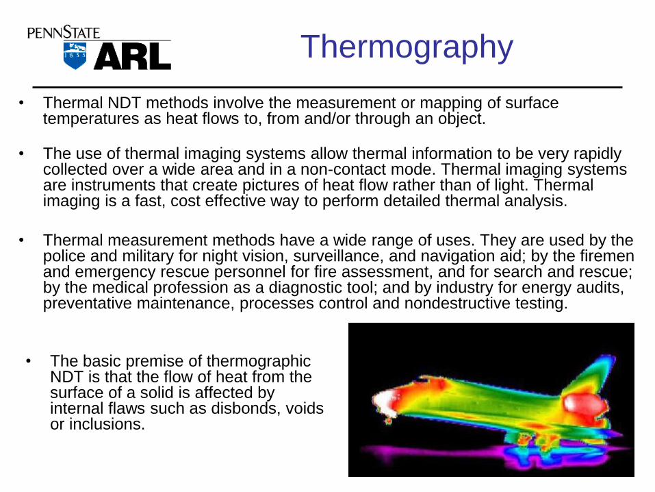
• Thermal NDT methods involve the measurement or mapping of surface temperatures as heat flows to, from and/or through an object.
• The use of thermal imaging systems allow thermal information to be very rapidly collected over a wide area and in a non-contact mode. Thermal imaging systems are instruments that create pictures of heat flow rather than of light. Thermal imaging is a fast, cost effective way to perform detailed thermal analysis.
• Thermal measurement methods have a wide range of uses. They are used by the police and military for night vision, surveillance, and navigation aid; by the firemen and emergency rescue personnel for fire assessment, and for search and rescue; by the medical profession as a diagnostic tool; and by industry for energy audits, preventative maintenance, processes control and nondestructive testing.
• The basic premise of thermographic NDT is that the flow of heat from the surface of a solid is affected by internal flaws such as disbonds, voids or inclusions.

23
Active Thermography
• Active thermography is a dynamic measurement method (thermal wave analysis).
• The wave is excited sinusoidally with halogen lamps, laser, or hot-air pistols on the surface of the tested component.
• It propagates wavelike in the testing object and is reflected at boundaries due to sudden changes in temperature conductivity and thermal impedance of the material.
Information provided by http://www.edevis.de/profile/profile_en.php

24
Aircraft Fuselage Inspection for
Corrosion
Slide provided by Sandia National Laboratory

27
Shearography and Holography
• Shearography and Holography systems image and measure test object surface profile changes down to 1 nanometer by analyzing the difference between two shifted or ‘sheared’ images.
• Subsurface defects cause local changes in the surface profile when the test part is subjected to a change in applied load. Typically these loads are in the form of heat, cold, pressure, vacuum, vibration or electromagnetic energy.
• These changes in surface profile reveal subsurface defects such as: – Disbonds, Unbonds, Delamination
– Core damage, Core splice disbonds, crushed core
– Impact Damage, Heat Damage
– Water Ingress
• Images are in JPEG, TIFF or other formats and are displayed for operator interpretation or evaluated automatically using ADR (Automatic Defect Recognition software). http://www.laserndt.com/about_02.htm

29
Shearography Applications
Shearing distance about 1 mm
NASA SWIFT Satellite BAT Mask
Identification of Poorly
Bonded Tiles
White Light Sheared Image
(No Fault Detection)
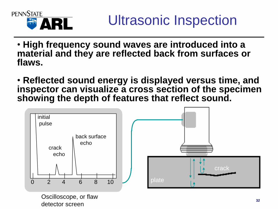
32
• High frequency sound waves are introduced into a material and they are reflected back from surfaces or flaws.
• Reflected sound energy is displayed versus time, and inspector can visualize a cross section of the specimen showing the depth of features that reflect sound.
f
plate
crack
0 2 4 6 8 10
initial
pulse
crack
echo
back surface
echo
Oscilloscope, or flaw
detector screen
Ultrasonic Inspection

36
Benchmark
Data Sets
Feature
Extraction
DATA-DRIVEN APPROACH
Feature Processing/
Modeling
MODEL-DRIVEN APPROACH
User-
Centric
Interface
Data
AcquisitionAutomated
Reasoning
Data
FusionInformation
Tu
rbin
e E
ng
ine
wit
h S
en
so
rs
Sensors include:
rotation speed,
temperature,
pressure, oil quality
vibration, etc.
Turbine Health Monitoring

Proficy SmartSignal
PREDICTIVE ANALYTICS FOR
AFFORDABLE READINESS

Reliability Based MaintenanceNow Realistically Within Reach
Monitoring
Software
5-10 min
Sampling
Monitor Failure Pattern # xx
- If found, follow Work Template # xx
Monitoring
Software
5-10 min
Sampling
Monitoring
Software
5-10 min
Sampling
Monitoring
Software
5-10 min
Sampling
Monitoring
Software
5-10 min
Sampling
Monitoring
Software
5-10 min
Sampling
Is detecting or predicting failure feasible?
Effects Driven
Optimization
xx
xx
Focusing on the right work
sooner and more effectively

Engineered, Templated, Scalable Turbine Functional Model Example

Easy User Interaction with Normalized Data
Deviations from
Healthy Patterns
“Blue is True”Where Your Data Is
“Green is Good”Where Your Data Should Be
Amps
Vibr
Temp
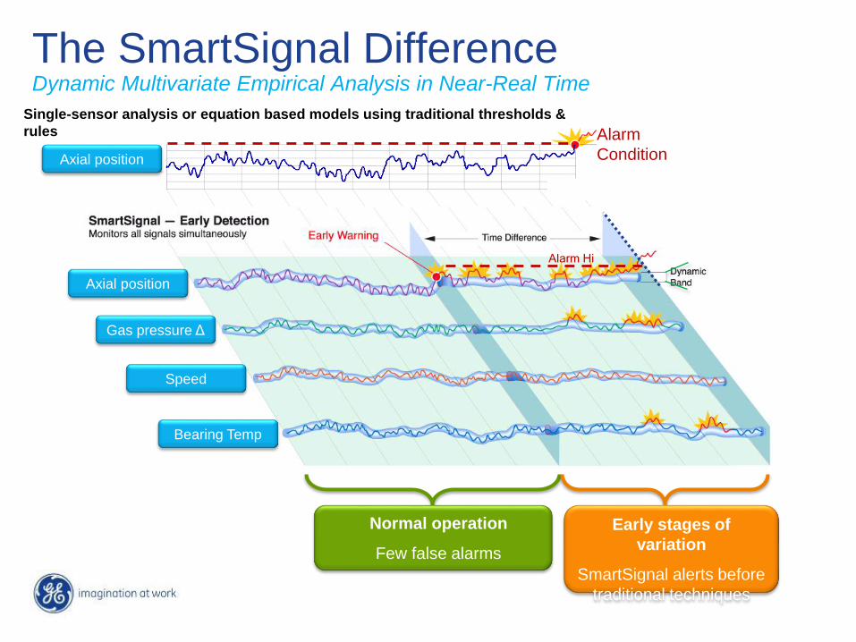
The SmartSignal DifferenceDynamic Multivariate Empirical Analysis in Near-Real Time
Axial position
Gas pressure Δ
Speed
Alarm Hi
Bearing Temp
Alarm
ConditionAxial position
Single-sensor analysis or equation based models using traditional thresholds &
rules
Early stages of
variation
SmartSignal alerts before
traditional techniques
Normal operation
Few false alarms

Current status, localizes
to problem area
Status details: trends,
compliance, remaining life
Easy User Interaction with Normalized Data
44
Summary
• Condition Based Maintenance+ (CBM+): A proactive equipment
maintenance capability enabled by using system health indications to
predict functional failure ahead of the event and take appropriate action.
CBM+ consists of three basic elements:
– RCM Methodology. Reliability Centered Maintenance provides a
rigorous methodology for developing equipment maintenance task
requirements.
– CBM tasks. CBM Tasks are derived from the RCM process to monitor
equipment to identify impending failure and required maintenance
actions.
– Infrastructure. Implementing the infrastructure, consisting of
numerous technologies and enablers, required to make use of sensor-
based maintenance information.