overview of gnss navigation sources, … of gnss...• gps can meet some, but not all, icao...
TRANSCRIPT

© 2008 The MITRE Corporation. All rights reserved.
Overview of GNSS Navigation Sources, Augmentation Systems, and Applications
The Ionosphere and its Effects on GNSS Systems14 to 16 April 2008
Santiago, Chile
Dr. S. Vincent Massimini
© 2008 The MITRE Corporation. All rights reserved.
13 of 301
Global Navigation Satellite Systems (GNSS)
• Global Positioning System (GPS)– U.S. Satellites
• GLONASS (Russia)– Similar concept
• Technically different
• Future: GALILEO– “Euro-GPS”
• Future: Beidou/Compass
© 2008 The MITRE Corporation. All rights reserved.
14 of 301
GPS

© 2008 The MITRE Corporation. All rights reserved.
15 of 301
Basic Global Positioning System (GPS)
Space SegmentSpace Segment
Ground SegmentGround Segment
User SegmentUser Segment
© 2008 The MITRE Corporation. All rights reserved.
16 of 301
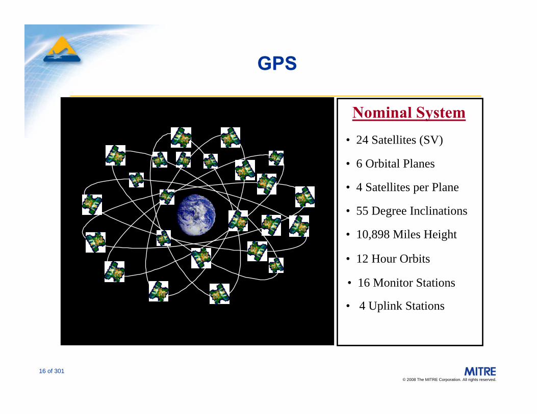
GPS
Nominal System• 24 Satellites (SV)
• 6 Orbital Planes
• 4 Satellites per Plane
• 55 Degree Inclinations
• 10,898 Miles Height
• 12 Hour Orbits
• 16 Monitor Stations
• 4 Uplink Stations
© 2008 The MITRE Corporation. All rights reserved.
17 of 301
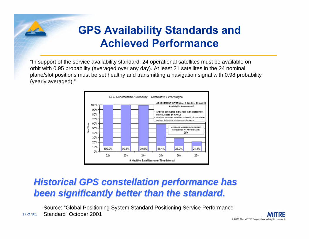
GPS Availability Standards and Achieved Performance
Source: “Global Positioning System Standard Positioning Service Performance Standard” October 2001
“In support of the service availability standard, 24 operational satellites must be available on orbit with 0.95 probability (averaged over any day). At least 21 satellites in the 24 nominal plane/slot positions must be set healthy and transmitting a navigation signal with 0.98 probability (yearly averaged).”
Historical GPS constellation performance has Historical GPS constellation performance has been significantly better than the standard.been significantly better than the standard.

© 2008 The MITRE Corporation. All rights reserved.
18 of 301
• 30 Healthy Satellites– 12 Block IIR satellites– 13 Block IIA satellites– 6 Block IIR-M satellites
• 2 additional IIR-M satellites to launch
• Since December 1993, U.S. has met/exceeded GPS service performance commitments
• U.S. committed to improving GPS service
GPS Constellation Status (30 March 2008)
18
© 2008 The MITRE Corporation. All rights reserved.
19 of 301
GPS Signals
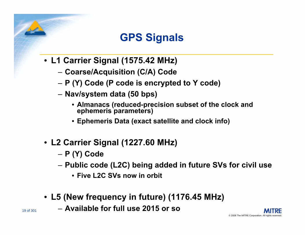
• L1 Carrier Signal (1575.42 MHz)– Coarse/Acquisition (C/A) Code– P (Y) Code (P code is encrypted to Y code)– Nav/system data (50 bps)
• Almanacs (reduced-precision subset of the clock and ephemeris parameters)
• Ephemeris Data (exact satellite and clock info)
• L2 Carrier Signal (1227.60 MHz)– P (Y) Code– Public code (L2C) being added in future SVs for civil use
• Five L2C SVs now in orbit
• L5 (New frequency in future) (1176.45 MHz)– Available for full use 2015 or so

© 2008 The MITRE Corporation. All rights reserved.
20 of 301
Current Positioning Systems
• Standard Positioning Service (SPS)– Single frequency receiver (L1)– C/A code and navigation/system data
• Precise Positioning Service (PPS)– Dual frequency receiver (L1 and L2)
• Technical advantages to using two frequencies
– C/A code, navigation/system data, and P(Y) code– Generally available to DOD and other approved users– Will not discuss further in this briefing

© 2008 The MITRE Corporation. All rights reserved.
21 of 301
Range and Velocity Measurement (SPS)
• Each satellite vehicle (SV) has a different 1023 bit pseudo random (PRN) code from which the user can determine the time of transmission
– Repeats each millisecond– Continuous/passive--not like DME or radar
• User velocity can be measured from Doppler shift or from sequential position measurements
“Code Phase”
GPS Clock(All SVs use same time base)
User Clock
© 2008 The MITRE Corporation. All rights reserved.
22 of 301
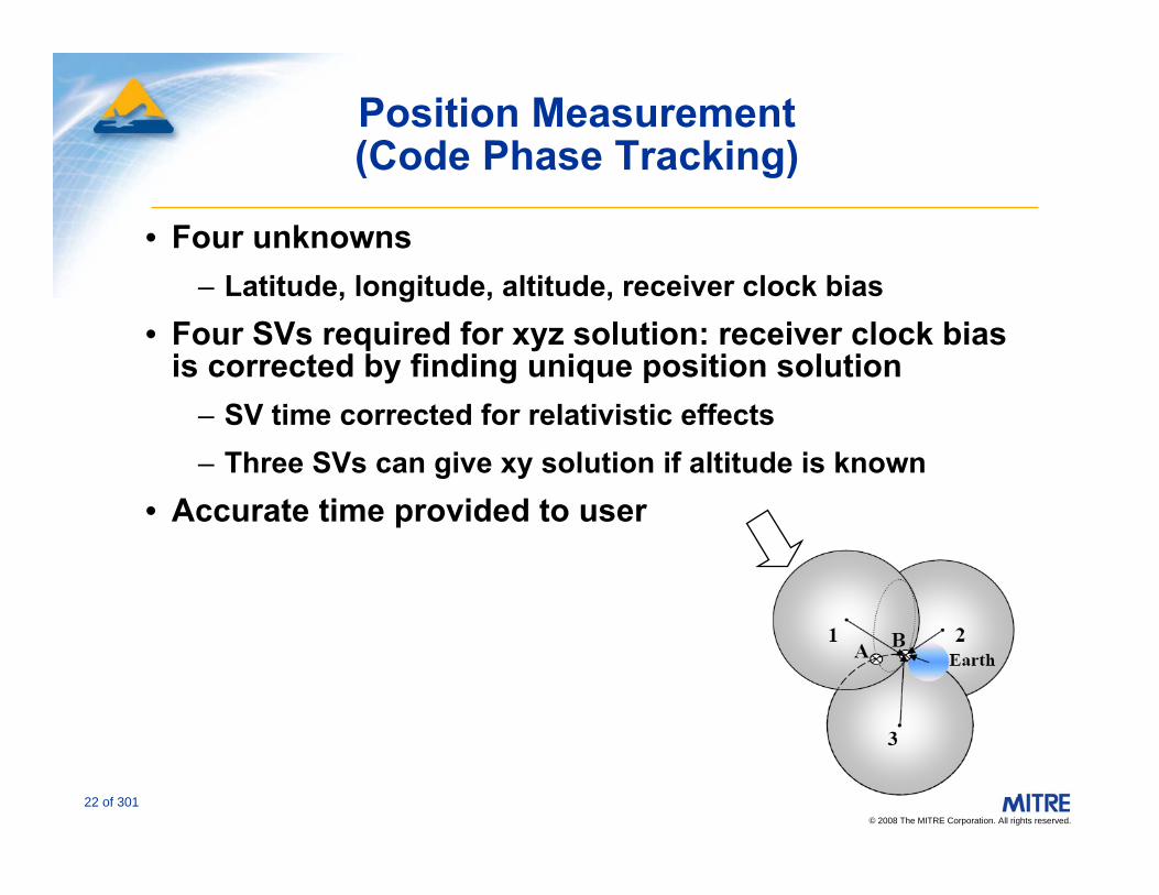
Position Measurement (Code Phase Tracking)
• Four unknowns – Latitude, longitude, altitude, receiver clock bias
• Four SVs required for xyz solution: receiver clock bias is corrected by finding unique position solution
– SV time corrected for relativistic effects– Three SVs can give xy solution if altitude is known
• Accurate time provided to user
© 2008 The MITRE Corporation. All rights reserved.
23 of 301
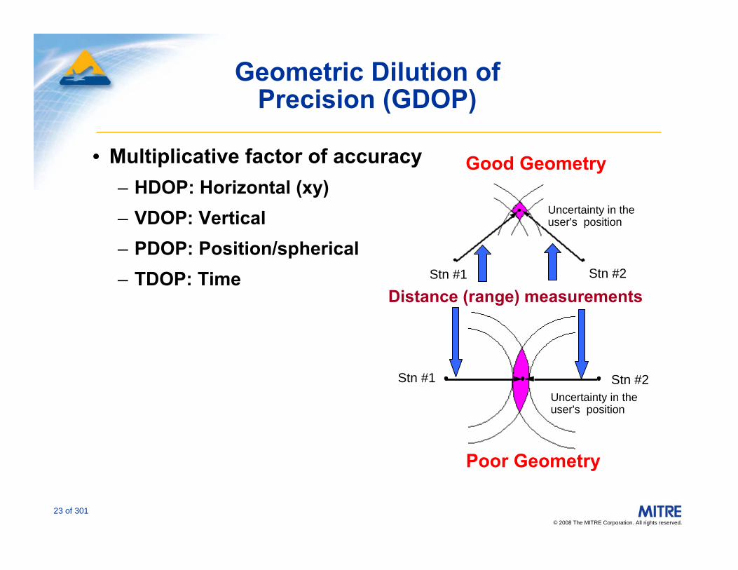
Geometric Dilution of Precision (GDOP)
• Multiplicative factor of accuracy– HDOP: Horizontal (xy)– VDOP: Vertical– PDOP: Position/spherical– TDOP: Time
Good Geometry
Stn #1
Uncertainty in theuser's position
Stn #2
Distance (range) measurements
Poor Geometry
Stn #2Uncertainty in theuser's position
Stn #1

© 2008 The MITRE Corporation. All rights reserved.
24 of 301
Ionosphere
True clock and location
Indicated clock and location
Troposphere
Multipath
Noise
Man-madeInterference
GPS Error Sources
Control Segment
Use of two frequencies removesnearly all of the ionospheric delay/error

© 2008 The MITRE Corporation. All rights reserved.
25 of 301
• BIAS Errors – SV clock errors & Ephemeris (~1-3 meters)– Atmospheric errors (~5-10 meters)– Multipath (~1-3 meters)
• Noise– < 1 meter (depends on equipment and geometry)
Ballpark Range Errors (1 σ)
© 2008 The MITRE Corporation. All rights reserved.
26 of 301
• GPS can meet some, but not all, ICAO performance requirements for Area Navigation (RNAV) without augmentation
• GPS is currently approved as supplemental aeronautical navigation use in en route, terminal areas and non-precision approach (NPA) – All IFR applications of unaugmented GPS depend on avionics
for integrity checks -- Receiver Autonomous Integrity Monitoring (RAIM)• “Aircraft-based Augmentation System” (ABAS) in ICAO
terminology• IFR GPS (with RAIM) is approved as a substitute for
ADF/DME/VOR in U.S.
• GPS is approved as primary means for oceanic navigation by the U.S.
• Use of unaugmented GPS/RAIM for vertical guidance has never been authorized
GPS in Civil Air Navigation

© 2008 The MITRE Corporation. All rights reserved.
27 of 301
Receiver Autonomous Integrity Monitoring (RAIM)
• Four SVs are required for xyz navigation solution• One bad SV could be detected if five SVs were available
(Fault Detection)• A bad SV could be isolated and eliminated with six or
more SVs available (Fault Detection and Exclusion (FDE))
• RAIM requires appropriate SV visibility and geometry• Can be augmented somewhat by Baro Aiding
• RAIM availability generally considered to be lower than desired for most instrument operations (as a primary means of navigation)
• Availability is satisfactory as a primary means for oceanic and remote area navigation (FDE required)
GeometryDependent
© 2008 The MITRE Corporation. All rights reserved.
28 of 301
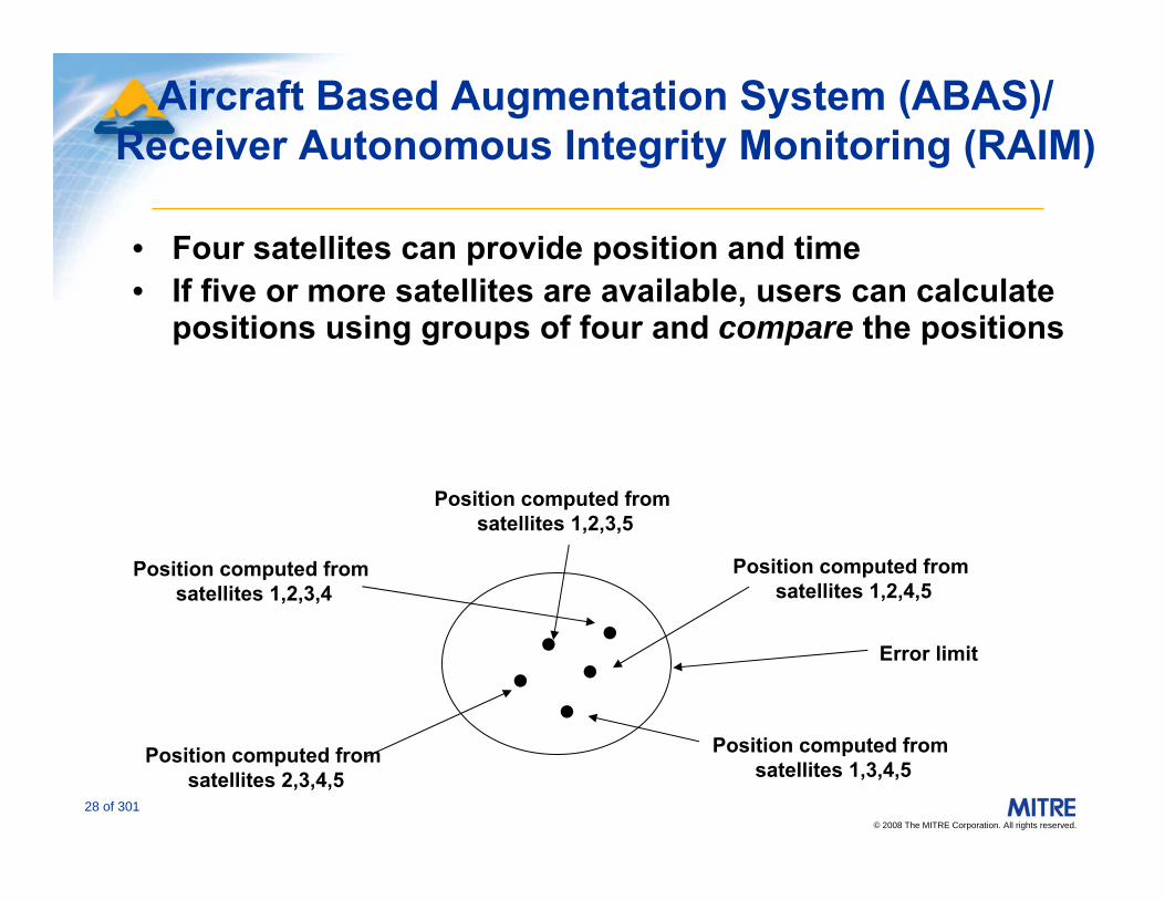
Aircraft Based Augmentation System (ABAS)/Receiver Autonomous Integrity Monitoring (RAIM)
• Four satellites can provide position and time• If five or more satellites are available, users can calculate
positions using groups of four and compare the positions
Position computed from satellites 1,2,3,4
Position computed from satellites 1,2,4,5
Position computed from satellites 1,2,3,5
Position computed from satellites 1,3,4,5
Position computed from satellites 2,3,4,5
●
●●● ● Error limit

© 2008 The MITRE Corporation. All rights reserved.
29 of 301
GPS Space Segment Modernization
• GPS Modernization began in 2000– Selective Availability (S/A) discontinued
• Retrofitted 8 Block IIR satellites with military code improvements and L2C signals (IIR-M)– Six now in orbit
• Block IIF– Above capabilities plus L5 civil signal
in protected band
• GPS III (Full modernization)– Increase power for military code– Program in the requirements and
architecture definition phase– New civil signals (e.g., L1C)

© 2008 The MITRE Corporation. All rights reserved.
30 of 301
GPS Modernization – Spectrum
ARNS* Band RNSS** Band ARNS* Band
1575.421227.6Frequency (MHz)
1176.45
-250
-240
-230
-220
Pow
er S
pect
rum
(dB
W/H
z)
1575.421227.6
-250
-240
-230
-220
Pow
er S
pect
rum
(dB
W/H
z)Frequency (MHz)
1575.421227.6Frequency (MHz)
1176.45
-250
-240
-230
-220
Pow
er S
pect
rum
(dB
W/H
z)
1575.421227.6
-250
-240
-230
-220P
ower
Spe
ctru
m (d
BW
/Hz)
Frequency (MHz)
P(Y)*** C/A
L5
M***L2C
L1C
L1L2
L5
Block IIA, 1990
Block III, 2013
Block IIR-M, 2005
Block IIF, 2008
as of Dec 2005as of Dec 2005
(artist’s concept)
plannedplanned
previousprevious
*Aeronautical Radio Navigation Service **Radio Navigation Satellite Service ***Military Codes

© 2008 The MITRE Corporation. All rights reserved.
31 of 301
• Integrity– Time to alarm from DoD: 15 - 360 min (typical 45 min)
• Accuracy– GPS accuracy generally satisfactory for en route and non-
precision approaches– Insufficient for precision approaches
• Accuracy insufficient (but getting close) even with SA off
• Availability– Sufficient SVs in view– Geometry for reasonable DOP
• Augmentation systems were developed for correction of these limitations
Augmentation of GPS
© 2008 The MITRE Corporation. All rights reserved.
32 of 301
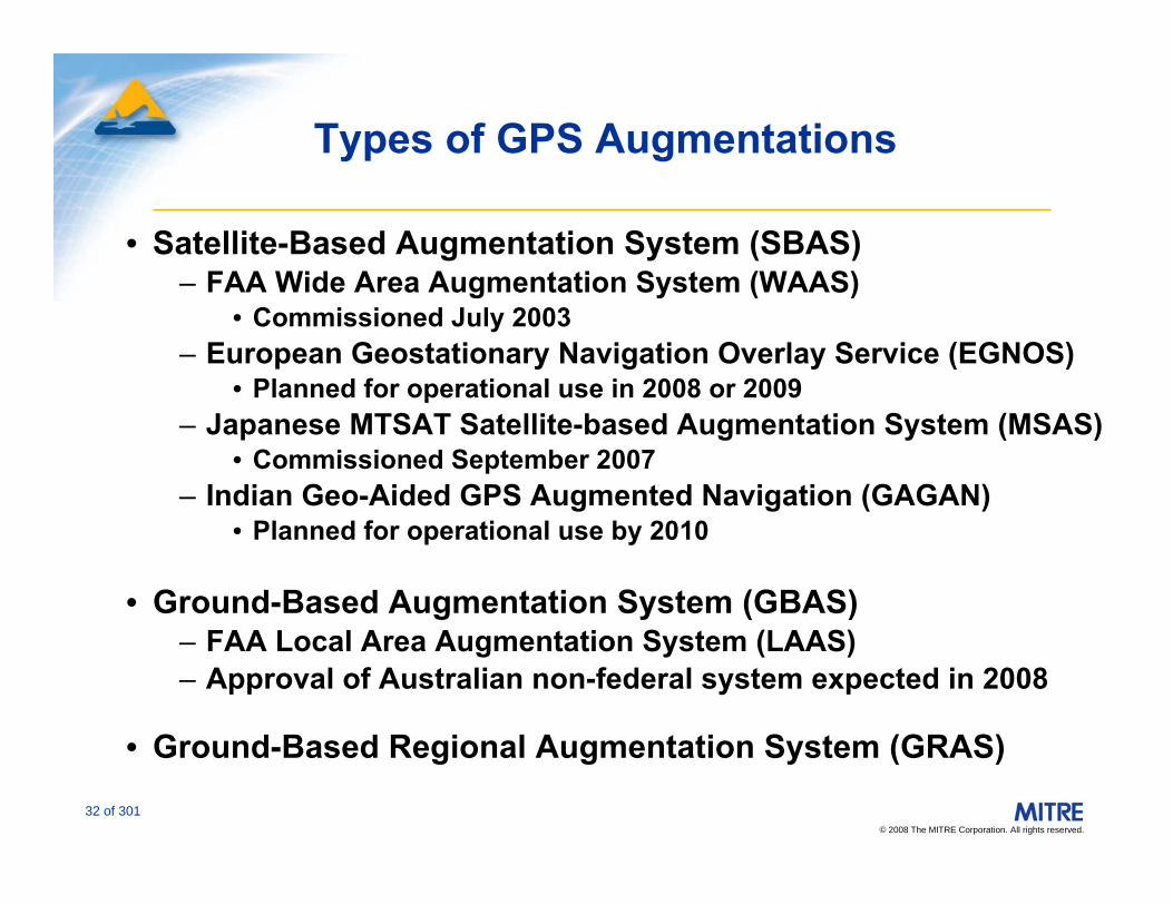
Types of GPS Augmentations
• Satellite-Based Augmentation System (SBAS)– FAA Wide Area Augmentation System (WAAS)
• Commissioned July 2003– European Geostationary Navigation Overlay Service (EGNOS)
• Planned for operational use in 2008 or 2009– Japanese MTSAT Satellite-based Augmentation System (MSAS)
• Commissioned September 2007– Indian Geo-Aided GPS Augmented Navigation (GAGAN)
• Planned for operational use by 2010
• Ground-Based Augmentation System (GBAS) – FAA Local Area Augmentation System (LAAS)– Approval of Australian non-federal system expected in 2008
• Ground-Based Regional Augmentation System (GRAS)
© 2008 The MITRE Corporation. All rights reserved.
33 of 301
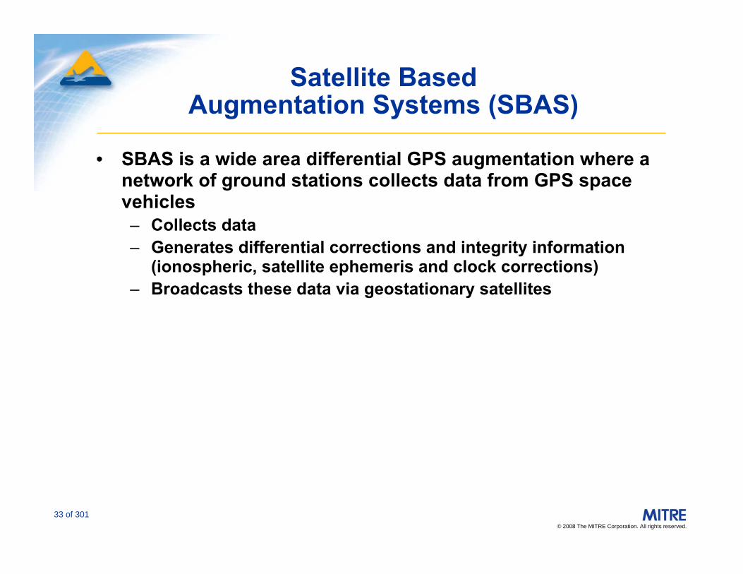
Satellite Based Augmentation Systems (SBAS)
• SBAS is a wide area differential GPS augmentation where a network of ground stations collects data from GPS space vehicles– Collects data– Generates differential corrections and integrity information
(ionospheric, satellite ephemeris and clock corrections)– Broadcasts these data via geostationary satellites

© 2008 The MITRE Corporation. All rights reserved.
34 of 301
The FAA SBAS: WAAS
• WAAS consists of – Ground reference stations and network– Ground Master Stations– Geosynchronous SVs– Corrections transmitted on L1 (GPS-like signal)
• WAAS provides– Integrity monitoring – Additional ranging from Geo SVs– Clock and ephemeris corrections– Ionospheric information by grid
• Operational as of 10 July 2003

© 2008 The MITRE Corporation. All rights reserved.
35 of 301
GPS Satellites
Communication Satellite(with WAAS transponder)
Ground EarthStations
Wide AreaMaster Station
Wide AreaReference Station
GPS
WAAS
Correction Terms,
Integrity Data
GPS-LikeSignals
Wide Area Augmentation System (WAAS)

© 2008 The MITRE Corporation. All rights reserved.
36 of 301
Wide Area Augmentation SystemNorth American Site Locations
Source: Federal Aviation Administration
© 2008 The MITRE Corporation. All rights reserved.
37 of 301
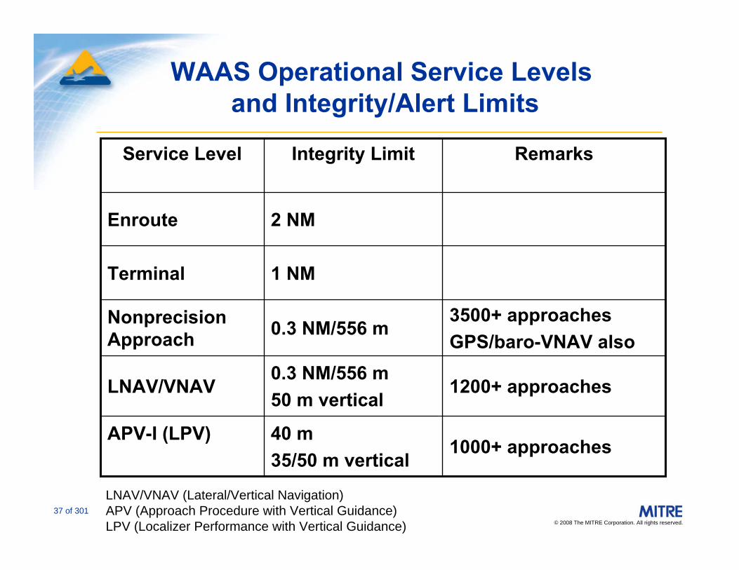
WAAS Operational Service Levelsand Integrity/Alert Limits
1000+ approaches40 m 35/50 m vertical
APV-I (LPV)
1200+ approaches0.3 NM/556 m50 m vertical
LNAV/VNAV
3500+ approachesGPS/baro-VNAV also
0.3 NM/556 mNonprecision Approach
1 NMTerminal
2 NMEnroute
RemarksIntegrity LimitService Level
LNAV/VNAV (Lateral/Vertical Navigation)APV (Approach Procedure with Vertical Guidance)LPV (Localizer Performance with Vertical Guidance)
© 2008 The MITRE Corporation. All rights reserved.
38 of 301
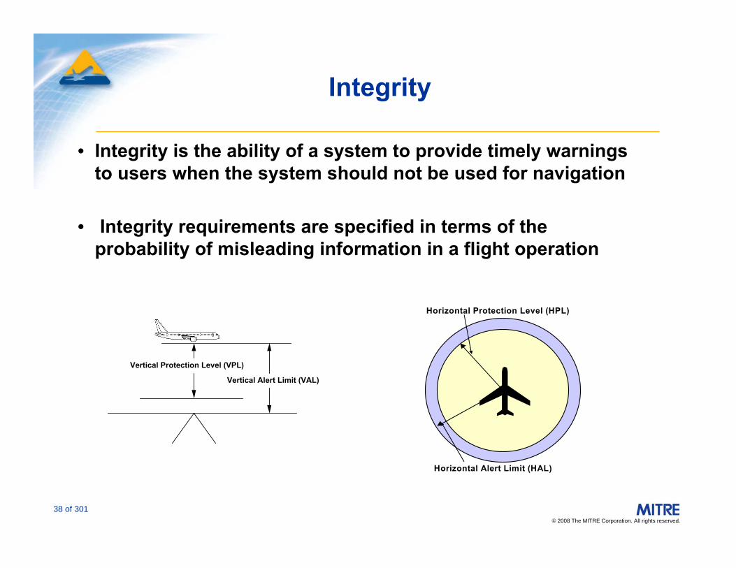
Integrity
• Integrity is the ability of a system to provide timely warnings to users when the system should not be used for navigation
• Integrity requirements are specified in terms of the probability of misleading information in a flight operation
Horizontal Alert Limit (HAL)
Horizontal Protection Level (HPL)
Vertical Protection Level (VPL)
Vertical Alert Limit (VAL)
© 2008 The MITRE Corporation. All rights reserved.
39 of 301
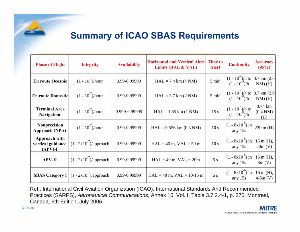
Summary of ICAO SBAS Requirements
Ref.: International Civil Aviation Organization (ICAO), International Standards And Recommended Practices (SARPS), Aeronautical Communications, Annex 10, Vol. I, Table 3.7.2.4-1, p. 370, Montreal, Canada, 6th Edition, July 2006.
Phase of Flight Integrity Availability Horizontal and Vertical Alert Limits (HAL & VAL)
Time to Alert Continuity Accuracy
(95%)
En route Oceanic (1 - 10-7)/hour 0.99-0.99999 HAL = 7.4 km (4 NM) 5 min (1 - 10-4)/h to (1 - 10-8)/h
3.7 km (2.0 NM) (H)
En route Domestic (1 - 10-7)/hour 0.99-0.99999 HAL = 3.7 km (2 NM) 5 min (1 - 10-4)/h to (1 - 10-8)/h
3.7 km (2.0 NM) (H)
Terminal Area Navigation (1 - 10-7)/hour 0.999-0.99999 HAL = 1.85 km (1 NM) 15 s (1 - 10-4)/h to
(1 - 10-8)/h
0.74 km (0.4 NM)
(H)
Nonprecision Approach (NPA) (1 - 10-7)/hour 0.99-0.99999 HAL = 0.556 km (0.3 NM) 10 s (1 - 8x10⁻⁶) in
any 15s 220 m (H)
Approach with vertical guidance
(APV)-I(1 - 2x10⁻⁷)/approach 0.99-0.99999 HAL = 40 m, VAL = 50 m 10 s (1 - 8x10⁻⁶) in
any 15s16 m (H), 20m (V)
APV-II (1 - 2x10⁻⁷)/approach 0.99-0.99999 HAL = 40 m, VAL = 20m 6 s (1 - 8x10⁻⁶) in any 15s
16 m (H), 8m (V)
SBAS Category I (1 - 2x10⁻⁷)/approach 0.99-0.99999 HAL = 40 m, VAL = 10-15 m 6 s (1 - 8x10⁻⁶) in any 15s
16 m (H), 4-6m (V)

© 2008 The MITRE Corporation. All rights reserved.
40 of 301
GPS and WAAS Horizontal Integrity/Alert Limits vs Service Availability
GPS or WAAS Non Precision Approach (0.3 NM horizontal, barometric vertical guidance)
WAAS LPV (40 m horizontal, 35 m* or 50 m vertical)
GPS or WAAS Terminal Area Navigation (1 NM horizontal)
GPS or WAAS En Route Navigation (2 NM horizontal)
Navigation service is unavailable Navigation service is unavailable whenever the realwhenever the real--time error bound time error bound (protection level) exceeds the integrity (protection level) exceeds the integrity limit(s).limit(s).
*35 m for approaches to below 250 ft.
© 2008 The MITRE Corporation. All rights reserved.
41 of 301
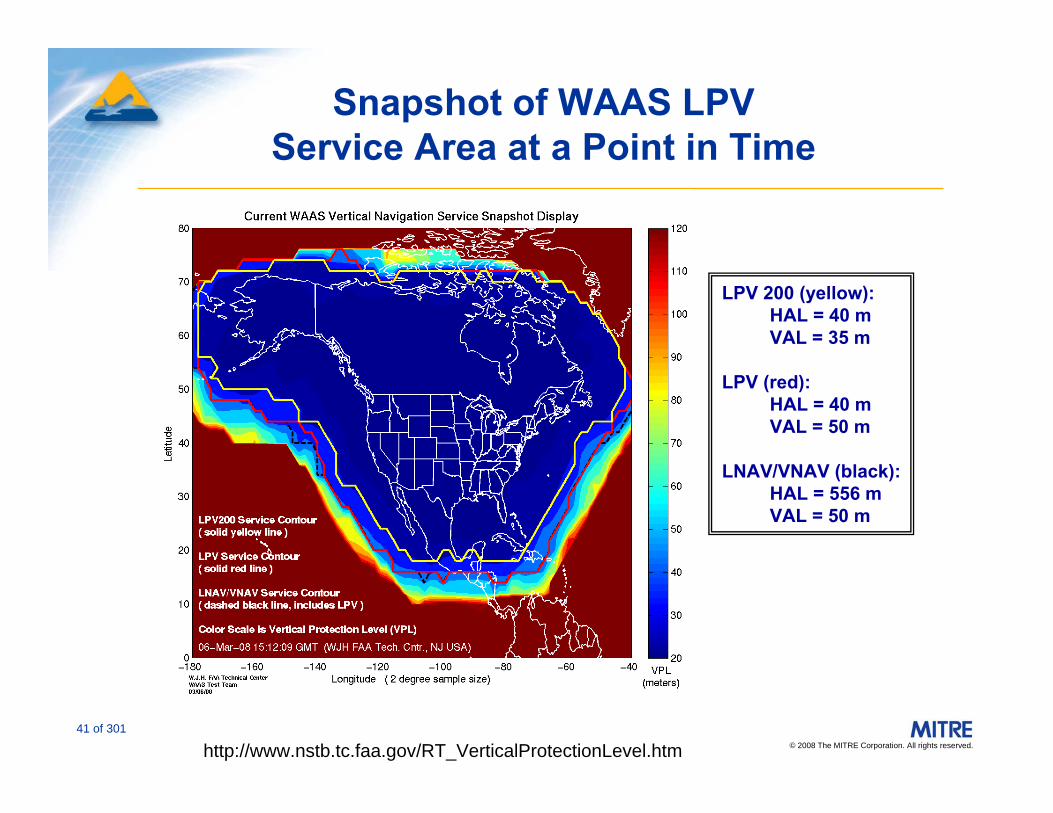
Snapshot of WAAS LPV Service Area at a Point in Time
LPV 200 (yellow):HAL = 40 mVAL = 35 m
LPV (red): HAL = 40 mVAL = 50 m
LNAV/VNAV (black):HAL = 556 mVAL = 50 m
http://www.nstb.tc.faa.gov/RT_VerticalProtectionLevel.htm
© 2008 The MITRE Corporation. All rights reserved.
42 of 301
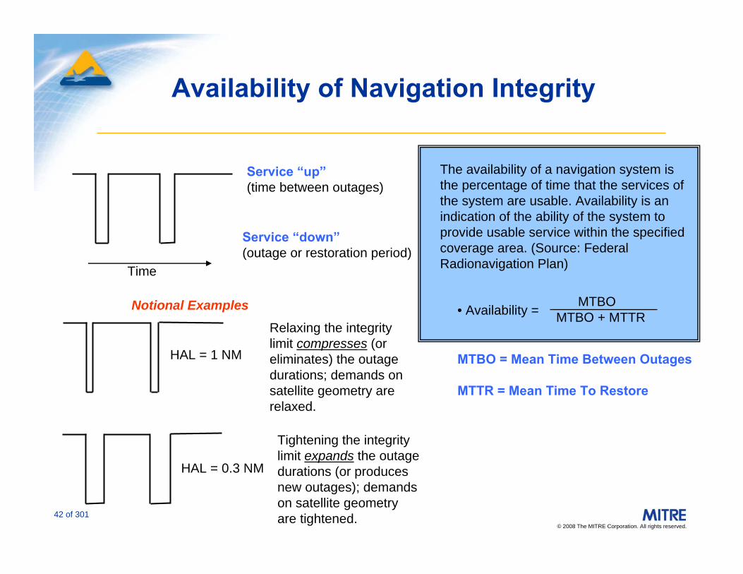
Availability of Navigation Integrity
Service “up”(time between outages)
Service “down”(outage or restoration period)
Time
MTBO = Mean Time Between Outages
MTTR = Mean Time To Restore
MTBOMTBO + MTTR
The availability of a navigation system is the percentage of time that the services of the system are usable. Availability is an indication of the ability of the system to provide usable service within the specified coverage area. (Source: Federal Radionavigation Plan)
• Availability = Relaxing the integrity limit compresses (or eliminates) the outage durations; demands on satellite geometry are relaxed.
Tightening the integrity limit expands the outage durations (or produces new outages); demands on satellite geometry are tightened.
HAL = 1 NM
HAL = 0.3 NM
Notional Examples
© 2008 The MITRE Corporation. All rights reserved.
43 of 301
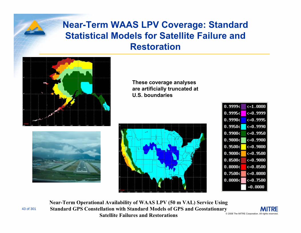
Near-Term WAAS LPV Coverage: Standard Statistical Models for Satellite Failure and
Restoration
Near-Term Operational Availability of WAAS LPV (50 m VAL) Service Using Standard GPS Constellation with Standard Models of GPS and Geostationary
Satellite Failures and Restorations
These coverage analyses are artificially truncated at U.S. boundaries
© 2008 The MITRE Corporation. All rights reserved.
44 of 301
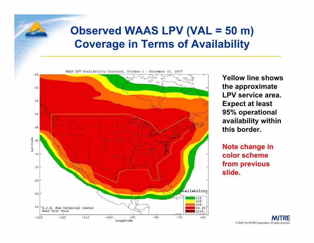
Observed WAAS LPV (VAL = 50 m) Coverage in Terms of Availability
Yellow line shows the approximate LPV service area. Expect at least 95% operational availability within this border.
Note change in color scheme from previous slide.
© 2008 The MITRE Corporation. All rights reserved.
45 of 301
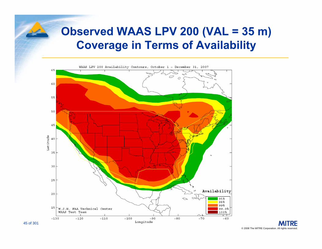
Observed WAAS LPV 200 (VAL = 35 m) Coverage in Terms of Availability
© 2008 The MITRE Corporation. All rights reserved.
46 of 301
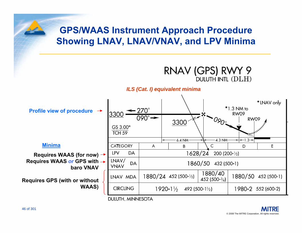
GPS/WAAS Instrument Approach Procedure Showing LNAV, LNAV/VNAV, and LPV Minima
Requires WAAS (for now)Requires WAAS or GPS with
baro VNAV
Requires GPS (with or without WAAS)
Profile view of procedure
Minima
ILS (Cat. I) equivalent minima

© 2008 The MITRE Corporation. All rights reserved.
47 of 301
CONUS
ALASKA
*Initial Operational Capability (IOC)
*Note: WAAS commissioned for IOC in July 2003
AVAILABILITY
2003 2004 2005 2006 2007 2008
Planned Evolution of WAAS LPV (50 m VAL, 40 m HAL)
Full LPV Performance (FLP)
Planned ImprovementsInclude Releases 2 – 8
© 2008 The MITRE Corporation. All rights reserved.
48 of 301
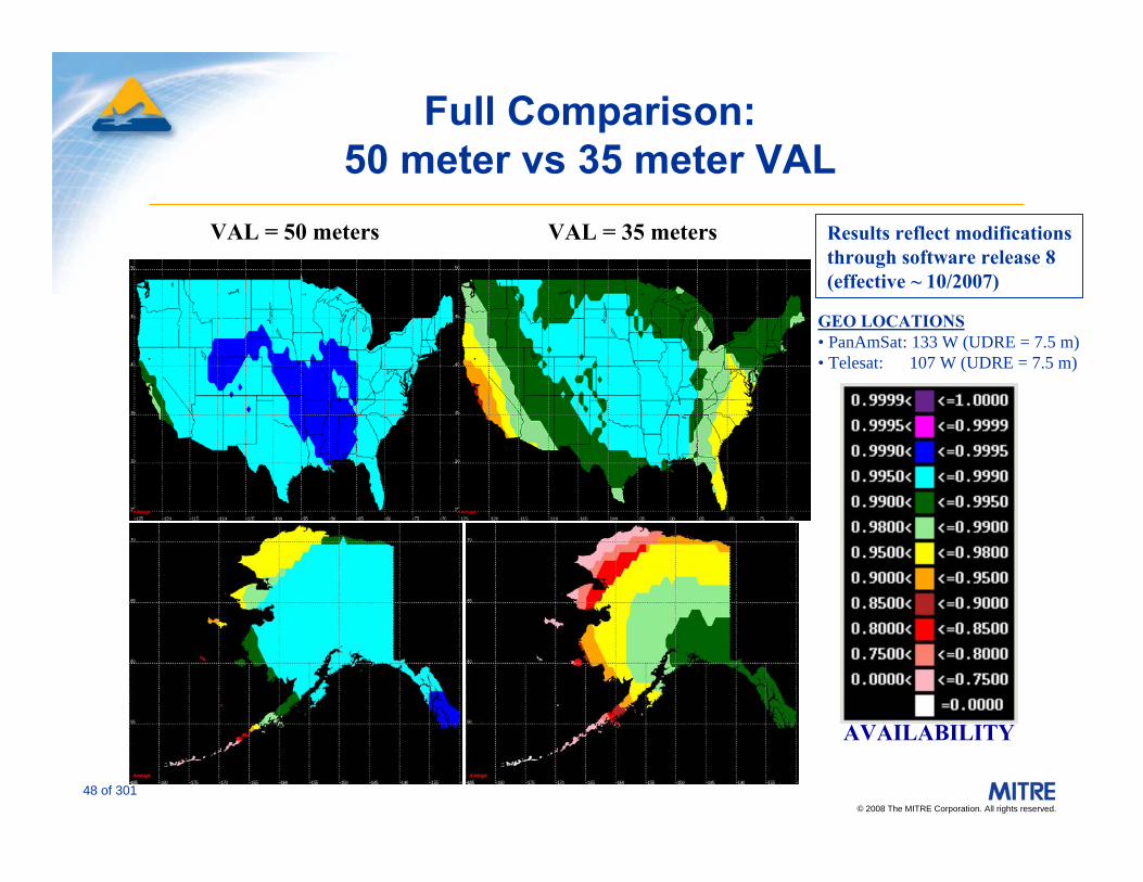
Full Comparison: 50 meter vs 35 meter VAL
AVAILABILITY
GEO LOCATIONS• PanAmSat: 133 W (UDRE = 7.5 m)• Telesat: 107 W (UDRE = 7.5 m)
VAL = 35 metersVAL = 50 meters Results reflect modificationsthrough software release 8(effective ~ 10/2007)

© 2008 The MITRE Corporation. All rights reserved.
49 of 301
Ground-Based Augmentation System (GBAS)U.S. Local Area Augmentation System (LAAS)
Source: Federal Aviation Administration.

© 2008 The MITRE Corporation. All rights reserved.
50 of 301
Ground-Based Regional Augmentation System (GRAS)
• GRAS Concept– Like SBAS, GRAS employs reference station network and
master stations to generate wide-area corrections and integrity information
– But transmits information through GBAS-like VHF datalink– User receives data with GBAS avionics and modified s/w
GPS Constellation
GRS GMSSatcom orTerrestrial
Links
Satcom orTerrestrial
Links GVS
LL
L
VHF
Users
GRAS Master Station• processes GRS data• determines GPS
corrections & integrity status
• generates SBAS messages
GRAS Ref. Stn• collects GPS
meas. & data• formats/sends
data to GMS
GRAS VHF Stn•Receives &
verifies SBAS messages
•converts to GBAS..format
•broadcasts GRASmessages at VHF
User Equip.•receives GPS
& GRAS data•computes
SARPs-based nav solution
GPS Constellation
GRS GMSSatcom orTerrestrial
Links
Satcom orTerrestrial
Links
Satcom orTerrestrial
Links
Satcom orTerrestrial
Links GVS
LL
L
VHF
Users
GRAS Master Station• processes GRS data• determines GPS
corrections & integrity status
• generates SBAS messages
GRAS Ref. Stn• collects GPS
meas. & data• formats/sends
data to GMS
GRAS VHF Stn•Receives &
verifies SBAS messages
•converts to GBAS..format
•broadcasts GRASmessages at VHF
User Equip.•receives GPS
& GRAS data•computes
SARPs-based nav solution

© 2008 The MITRE Corporation. All rights reserved.
51 of 301
GPS Improvements in Civil Aviation1 of 3
• GPS is enabling a revolution in aviation– Strong user support– Major users are general aviation pilots– New GPS units combining communications, conventional
navigation, and a multi-function display have been introduced and are becoming very popular
– Air carrier equipage has been slower, but is steadily increasing
• Augmentation systems (i.e., SBAS, GBAS, GRAS) offer increased capability– Precision approach– Increased availability of GPS navigation signals usable for
navigation

© 2008 The MITRE Corporation. All rights reserved.
52 of 301
GPS Improvements in Civil Aviation 2 of 3
• Cockpit navigation and safety– Combination with modern automation provides
improved navigation potential for all aircraft, especially domestic aircraft without area nav systems
• Terrain Awareness Warning System (TAWS) is available using GPS and digital terrain data– Large improvement expected over current radar-
altimeter based GPWS systems
• Precision approach capability at nearly all instrument runways
• Enabling technology for surface navigation and surveillance

© 2008 The MITRE Corporation. All rights reserved.
53 of 301
GPS Improvements in Civil Aviation 3 of 3
• Better minima for many approaches • Improved accuracy for oceanic/remote operations• Cost
– Augmented GPS can replace many VOR, DME, TACAN, NDB, ILS, and MLS in ground and avionics applications
• ATC/Capacity/Access– Increased numbers of vertically-guided approaches at smaller
airports– Simplification of non-radar approach procedures – Possible curved approaches and selectable glide paths– Precise navigation guidance for departures and missed
approaches– Broadcast of GPS position and velocity can improve air-
ground surveillance (ADS-B)

© 2008 The MITRE Corporation. All rights reserved.
54 of 301
Geodetic ReferencesWGS-84
• Prior to GPS, individual countries used individual geodesic datums to establish latitude/longitude– Individual datums were base on local survey monuments– Geodetic datum is not important using conventional
NAVAIDs, since aircraft position is relative to the NAVAID
• When using GPS, however, all navigation is referenced to latitude and longitude
• GPS uses the WGS-84 datum for all navigation worldwide– A position determined from a latitude/longitude derived
from GPS can vary by tens of meters when compared to a position with the same latitude/longitude derived from a local datum
• ICAO has standardized that all aviation waypoints must be expressed in WGS-84

© 2008 The MITRE Corporation. All rights reserved.
55 of 301
GALILEO

© 2008 The MITRE Corporation. All rights reserved.
56 of 301
Basic GALILEO Plans
• Five types of service:“open service”“safety of life service”“commercial service”“public regulated service”“search and rescue service”
• GPS-like orbits and signals• 27 to 30 SVs in three orbital planes• Orbits repeat ~ every 10 days• Expected to create ~100,000 new jobs• Initial Operating Capability: 2014 (?)
More information at: http://europa.eu.int/comm/dgs/energy_transport/galileo/index_en.htm

© 2008 The MITRE Corporation. All rights reserved.
57 of 301
Planned GALILEO Technical Characteristics (Safety of Life Service)
Source: GALILEO High Level Mission Definition, September 23, 2002
© 2008 The MITRE Corporation. All rights reserved.
58 of 301
GLONASS and Compass

© 2008 The MITRE Corporation. All rights reserved.
59 of 301
GLONASS and Compass
• GLONASS (Russian Space Agency)– Nominal 24 satellite constellation– 16 operational satellites as of March 6, 2008– Current target is to have 24 operational satellites by 2009
• Compass (Beidou: China)– Nominal constellation of 30 satellites in medium earth orbit,
plus 5 geostationary satellites– Four experimental satellites have been launched since 2000– Schedule: Operational by by 2017 (?)

© 2008 The MITRE Corporation. All rights reserved.
60 of 301
RNP Philosophy: Specify performance level rather than type of avionics.
Area Navigation (RNAV) and Required Navigation Performance (RNP)
© 2008 The MITRE Corporation. All rights reserved.
61 of 301
Characteristics of RNAV Systems
• RNAV systems:– Allow navigation along desired flight path without
requirement to overfly ground-based navigational aids– Automatically compute:
• Position • Distance and along track information • Steering commands
– May provide VNAV based on barometric altimetry
• Applications include en route, terminal area, and instrument approach procedures
• RNAV may be:– Stand-alone system (e.g., GPS)– Integrated function of other system (Flight Management
System (FMS))

© 2008 The MITRE Corporation. All rights reserved.
62 of 301
RNAV vs. Non-RNAV Routing: A Simplified Example
BRAVOBRAVOVORTACVORTAC
CHARLIECHARLIEVORTACVORTAC
ALPHAALPHAVORTACVORTAC
HOMEFIELDHOMEFIELDAirportAirport
20 NM20 NM
80 NM80 NM60 NM60 NM
25 NM25 NM100 NM100 NM
DESTINATIONDESTINATIONAirportAirport

© 2008 The MITRE Corporation. All rights reserved.
63 of 301
RNAV Flight Domains
• RNAV is now implemented in all flight domains– En route
• Oceanic (RNP)• High altitude continental RNAV routes (U.S. Q-Routes)• Low altitude continental RNAV routes (U.S. T-Routes)
– Terminal area• RNAV arrivals and departures
– Instrument Approach Procedures• RNAV (GPS)
– With and without vertical guidance• RNAV (RNP)
– Baro-VNAV (Special Aircraft and Aircrew Authorization Required, analogous to Cat. II/III ILS)
• RNP is currently implemented in oceanic and instrument approach domains
© 2008 The MITRE Corporation. All rights reserved.
64 of 301
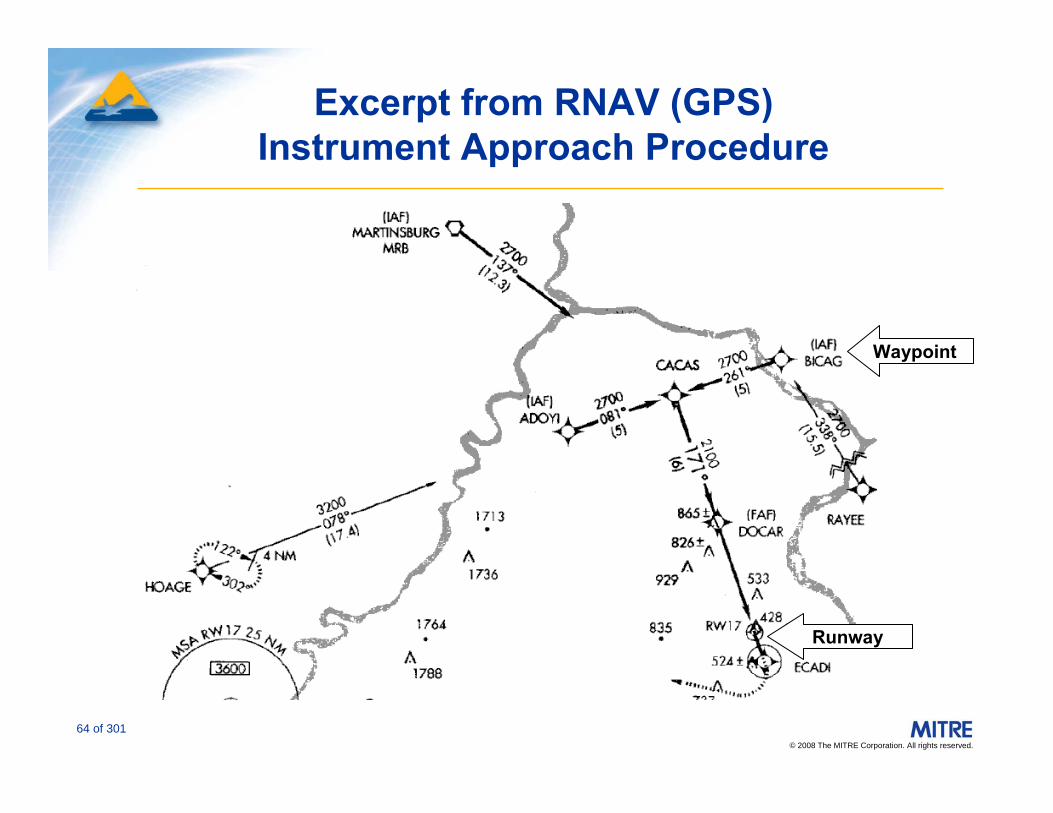
Excerpt from RNAV (GPS) Instrument Approach Procedure
Waypoint
Runway
© 2008 The MITRE Corporation. All rights reserved.
65 of 301
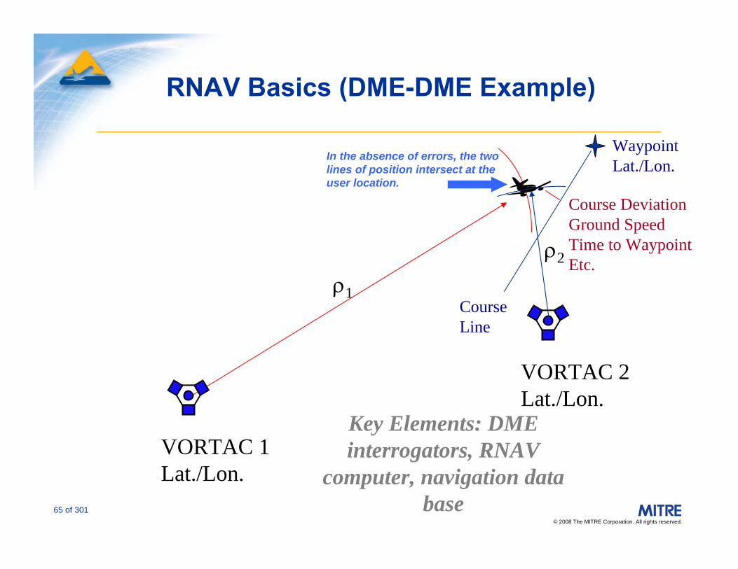
RNAV Basics (DME-DME Example)
ρ1
VORTAC 1Lat./Lon.
VORTAC 2Lat./Lon.
ρ2
WaypointLat./Lon.
Course Line
Course DeviationGround SpeedTime to WaypointEtc.
Key Elements: DME interrogators, RNAV
computer, navigation data base
In the absence of errors, the two lines of position intersect at the user location.

© 2008 The MITRE Corporation. All rights reserved.
66 of 301
DME-DME RNAV: Nominal En Route Coverage
Nominal RNAV Coverage at 18,000 ft MSLNominal RNAV Coverage at 18,000 ft MSL Nominal RNAV Coverage at 24,000 ft MSLNominal RNAV Coverage at 24,000 ft MSL
Redundant coverage (no critical facilities)Single critical facilityTwo critical facilitiesNo coverage
Redundant coverage (no critical facilities)Single critical facilityTwo critical facilitiesNo coverage
Nominal RNAV Service Coverage per AC 90-100A

© 2008 The MITRE Corporation. All rights reserved.
67 of 301
Other RNAV Technologies
GPS(Including
Augmentations),GALILEO,GLONASS
Loran-CeLORAN
Inertial

© 2008 The MITRE Corporation. All rights reserved.
68 of 301
Avionics for RNAV and RNP: Systems and Characteristics
• RNAV (VOR/DME)
• Long Range Navigation (LORAN)– Potential enhancements: eLORAN
• Inertial Navigation System (INS)
• Global Positioning System (GPS)
• Multi-Sensor RNAV Systems (FMS)
© 2008 The MITRE Corporation. All rights reserved.
69 of 301
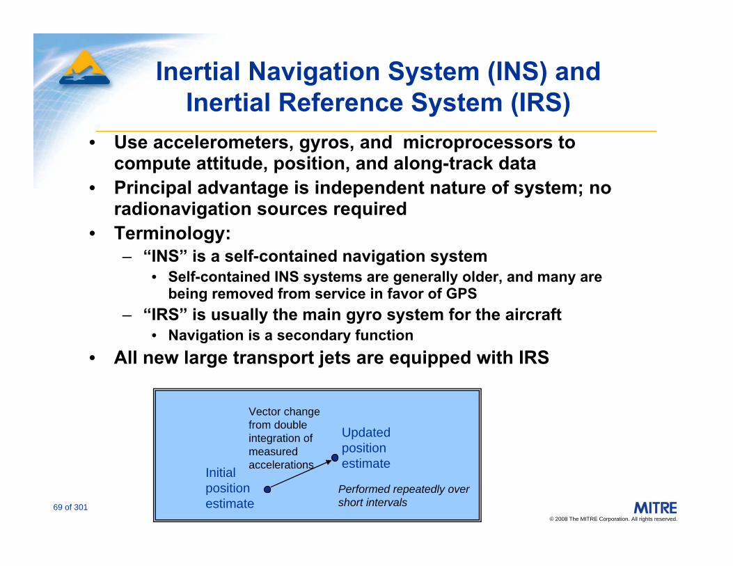
Inertial Navigation System (INS) and Inertial Reference System (IRS)
• Use accelerometers, gyros, and microprocessors to compute attitude, position, and along-track data
• Principal advantage is independent nature of system; no radionavigation sources required
• Terminology:– “INS” is a self-contained navigation system
• Self-contained INS systems are generally older, and many are being removed from service in favor of GPS
– “IRS” is usually the main gyro system for the aircraft• Navigation is a secondary function
• All new large transport jets are equipped with IRS
Vector change from double integration of measured accelerationsInitial
position estimate
Updated position estimate
Performed repeatedly over short intervals

© 2008 The MITRE Corporation. All rights reserved.
70 of 301
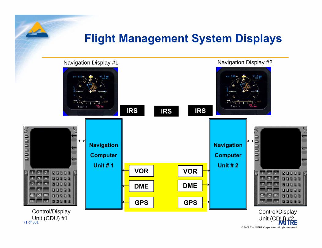
Flight Management System (FMS)
• System may use various combinations of VOR, DME, GPS, and/or IRS navigation sources– Virtually all FMS architectures use DME-DME RNAV– All new transport category aircraft are being delivered
with FMS and GPS as standard equipment
• GPS/IRS integration in FMSs: two distinct architectures– Loose coupling: IRS and GPS independently feed a
Kalman filter for a weighted solution; GPS continuously updates inertial position, but there is no calibration of IRS biases
– Tight coupling: GPS is used to calibrate biases in IRS as part of the Kalman filter arrangement
• FMS systems may combine horizontal navigation and barometric altitude to provide vertical navigation (VNAV) capability
© 2008 The MITRE Corporation. All rights reserved.
71 of 301
Flight Management System Displays
Navigation
Computer
Unit # 1
Navigation
Computer
Unit # 2VOR VOR
GPS GPS
DME DME
IRS IRS IRS
CDU CDU
Control/Display Unit (CDU) #1
Control/Display Unit (CDU) #2
Navigation Display #1 Navigation Display #2

© 2008 The MITRE Corporation. All rights reserved.
72 of 301
DesiredPath
Route Width
Cross trackError
ActualPosition
EstimatedPosition
FlightTechnicalErrorIndicated
Path
ActualPath
Along TrackError
System Errors
ICAO Required Navigation Performance (RNP) Concept
Briefing slides courtesy Dave Nakamura, Boeing/SC-181 (with editorial changes)
© 2008 The MITRE Corporation. All rights reserved.
73 of 301
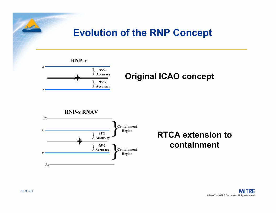
RNP-x95%
Accuracy}}
RNP-x RNAV
x
x
2x
2x
95% Accuracy
95% Accuracy}
}
x
x
95% Accuracy
}ContainmentRegion
}ContainmentRegion
Original ICAO concept
RTCA extension to containment
Evolution of the RNP Concept
© 2008 The MITRE Corporation. All rights reserved.
74 of 301
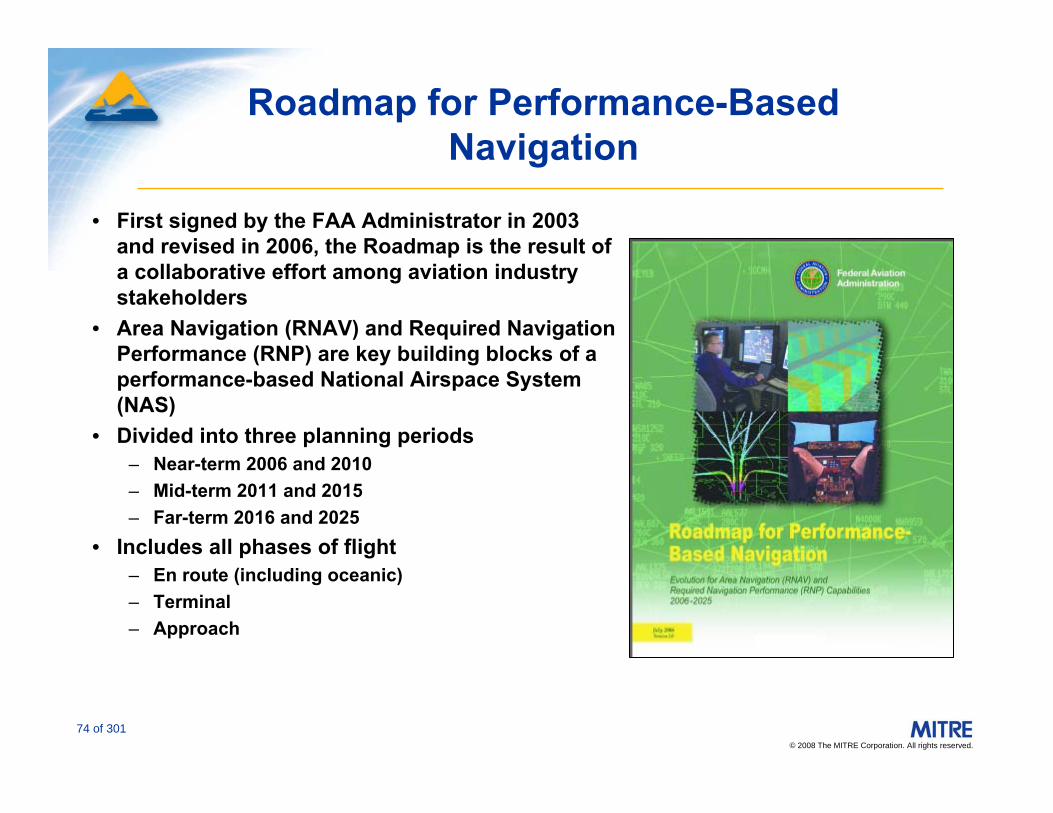
Roadmap for Performance-Based Navigation
• First signed by the FAA Administrator in 2003 and revised in 2006, the Roadmap is the result of a collaborative effort among aviation industry stakeholders
• Area Navigation (RNAV) and Required Navigation Performance (RNP) are key building blocks of a performance-based National Airspace System (NAS)
• Divided into three planning periods – Near-term 2006 and 2010 – Mid-term 2011 and 2015 – Far-term 2016 and 2025
• Includes all phases of flight– En route (including oceanic) – Terminal– Approach

© 2008 The MITRE Corporation. All rights reserved.
75 of 301
FAA PBN Application
RNP-1SIDs*
RNP-2EN ROUTE
RNP-1STARs**
RNP-0.3APPROACHES
* Standard Instrument Departures (SIDs) ** Standard Terminal Arrivals (STARs)

© 2008 The MITRE Corporation. All rights reserved.
76 of 301
Potential Benefits and Use of Performance-Based Navigation
• Incremental procedure implementation– Measure benefits,– Resolve issues– Apply lessons learned
• Incentive-based implementation in near term • Possible mandates in mid- and long-term• Coordination with airspace redesign efforts and other programs for maximum benefit• Strategy based on international harmonization considerations
Reduction in noise and emissions
Reduction in noise and emissions
Reduction in noise and emissions
Environment
More direct routing
Reduction in delays
Enhanced descent profilesEfficiency
Reduction in lateral route separation
Increase in exit/entry points
Increased runway availability
Capacity
Reduced radio transmissions
Reduced radio transmissions
Stabilized vertical pathsSafety
En RouteTerminalApproachBenefits

© 2008 The MITRE Corporation. All rights reserved.
77 of 301
• Design• Evaluation• Data exchange• Simulation
TARGETS RNAV Design Tool

© 2008 The MITRE Corporation. All rights reserved.
78 of 301
Aircraft Capability:U.S. Aircraft Equipment Suffixes
RVSM /W
/R with RVSM /Q
/G with RVSM /L
/F with RVSM/K
/E with RVSM /J
REDUCED VERTICAL SEPARATION MINIMA (RVSM). Prior to conducting RVSM operations within the U.S., the operator must obtain authorization from the FAA or from the responsible authority, as appropriate
Required Navigational Performance. The aircraft meets the RNP type prescribed for the route segment(s), route(s) and/or area concerned
/R
Global Navigation Satellite System (GNSS), including GPS or WAAS, with en route and terminal capability./G
Flight Management System (FMS) with DME/DME position updating /F
Flight Management System (FMS) with DME/DME and IRU position updating/E
ADVANCED RNAV WITH TRANSPONDER AND MODE C (If an aircraft is unable to operate with a transponder and/or Mode C, it will revert to the appropriate code listed above under Area Navigation)
• Equipment suffixes are a generic description
• Suffixes do not necessarily convey capability– Aircrew training– FMC limitations
• Leg type• Route type
113.56 144113.56 002
213
© 2008 The MITRE Corporation. All rights reserved.
79 of 301
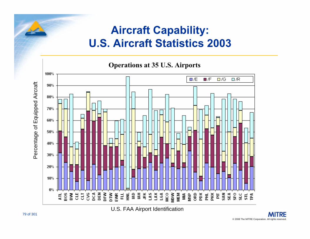
Aircraft Capability:U.S. Aircraft Statistics 2003
Operations at 35 U.S. Airports
Per
cent
age
of E
quip
ped
Airc
raft
U.S. FAA Airport Identification
© 2008 The MITRE Corporation. All rights reserved.
80 of 301
Example RNAV and RNP Procedures
© 2008 The MITRE Corporation. All rights reserved.
81 of 301
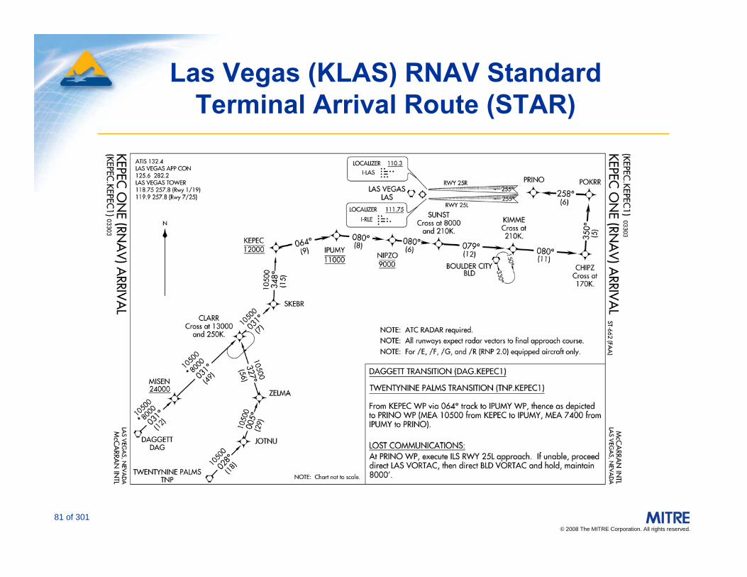
Las Vegas (KLAS) RNAV Standard Terminal Arrival Route (STAR)

© 2008 The MITRE Corporation. All rights reserved.
82 of 301
Atlanta (KATL) RNAV Standard Instrument Departure (SID)

© 2008 The MITRE Corporation. All rights reserved.
83 of 301
Washington National (KDCA) Visual and Instrument Approaches
3,500 ftCeiling
720 ftCeiling

© 2008 The MITRE Corporation. All rights reserved.
84 of 301
KDCA RNP Special Aircrew and Aircraft Authorization Required (SAAAR) Approach
• Safety enhancement, with guided, stabilized 3D path to runway
• Provides RNP corridor which avoids prohibited airspace
• SAAAR approach significantly improves availability of Runway 19 during low visibility conditions
– 475 ft ceiling

© 2008 The MITRE Corporation. All rights reserved.
85 of 301
John F. Kennedy (KJFK) Visual and RNP SAAAR Approaches
Courtesy: jetBlue Airways

© 2008 The MITRE Corporation. All rights reserved.
86 of 301
John F. Kennedy (KJFK) Visual and RNP SAAAR Approaches
ASALT
Red: 11 jetBlue RNP SAAAR OperationsYellow: Conventional VOR to Visual Operations

© 2008 The MITRE Corporation. All rights reserved.
87 of 301
RNP SAAAR at Palm Springs (KPSP)

© 2008 The MITRE Corporation. All rights reserved.
88 of 301
Future Directions and Trends1 of 2
• General aviation and air carrier aircraft are equipping with RNAV systems– Virtually all new aircraft come equipped with RNAV
capabilities as standard equipment
• ADFs and NDBs are on the way out in the U.S.
• Air carrier and high-end general aviation FMS systems permit “on-the-fly” planning capabilities to optimize the flight
• Low/mid-range general aviation GPS equipage with moving map displays will provide some of the capabilities formerly reserved for FMS-equipped aircraft

© 2008 The MITRE Corporation. All rights reserved.
89 of 301
Future Directions and Trends 2 of 2
• GALILEO and modernized GPS hold promises for significant new operational capabilities
• Widespread international interest in augmentation systems

© 2008 The MITRE Corporation. All rights reserved.
90 of 301
For Surfers Only (Selected Public Websites)
• http://www.caasd.org/proj/satnav/• http://www.faa.gov/airports_airtraffic/air_traffic/public
ations/ATpubs/AIM/• http://www.navcen.uscg.gov/• http://gps.faa.gov/• http://www.pnt.gov/• http://www.nstb.tc.faa.gov/• http://gps.losangeles.af.mil/ • http://europa.eu.int/comm/dgs/energy_transport/galile
o/index_en.htm• http://www.esa.int/export/esaSA/navigation.html• http://www.galileoju.com/