overview of mega-float: concept, design criteria and ... · hideyuki suzuki department of...
TRANSCRIPT

1
Very Large Floating Structures for the FutureNTNU, Oct 28-29 2004
Hideyuki SuzukiDepartment of Environmental and Ocean EngineeringUniversity of Tokyo
Overview of Mega-float:Concept, Design Criteria andAnalysis and Design
Outline of Presentation
1. Activities before Mega-float Project
2. Technological Research Association ofMega-float
3. Activities after Mega-float Project
(Ship Research Center and the Shipbuilders’Association of Japan)

2
History of Very Large Floating Structure inJapan
1960’s Puppet drama “Hykkori Hyouta Jima”1973-1974 Proposal of Floating Airport for Kansai international Airport
Phase 1 (semisubmersible type)1975 Okinawa International Ocean Exhibition1988 Kamigoto Oil Stock Pile
390m x 97m x 27.6m x 5Units1996 Shirashima Oil Stock Pile
397m x 82m x 25.1m x 8Unit1994 Proposal of Floating Runway for Kansai international Airport
Phase 2 (pontoon type)1995/5 Technological Research Association of Mega-float1995-1996 Phse1 Experiment
300m x 60m1997- Phase 2 Experiment
1000m x 60-120m, Landing & Takeoff Experiment
Puppet Drama
“Hyokkori HyoutannJima”
3
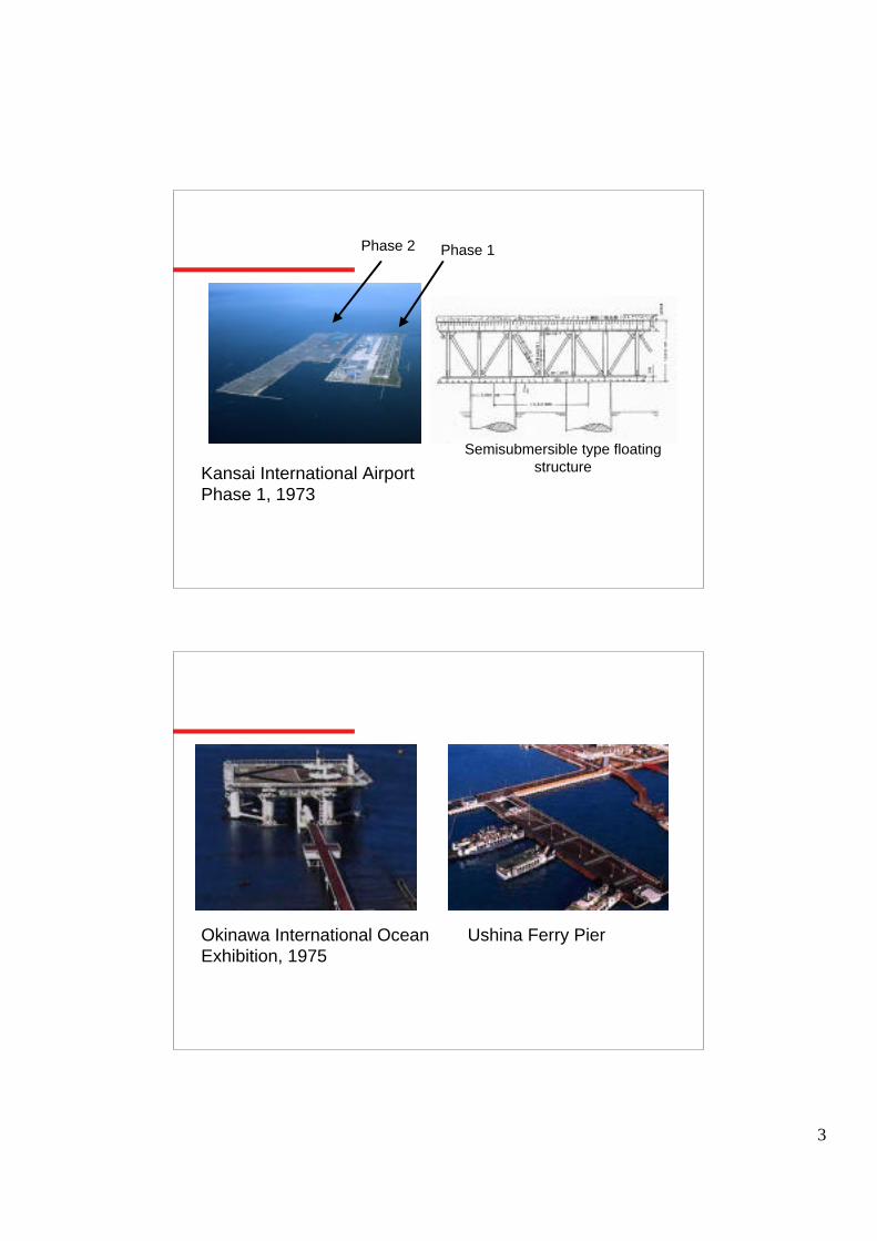
Kansai International AirportPhase 1, 1973
Semisubmersible type floatingstructure
Phase 1Phase 2
Okinawa International OceanExhibition, 1975
Ushina Ferry Pier

4
Floating Oil Stock Pile
National Oil Stock Pile (296.0Million bbl) Land 7 bases Sea 2 bases Underground 1 base
Stock of Private Sector ( 296.0Million bbl)
Kamigoto 1988 (27.7Million bbl)Shirashima 1996 (35.2Million bbl)
Floating City
Technological Research Association of Mega-float
1993Transport Technological Councilrecommended to promote Very LargeFloating Structure (Ministry of Land,Infrastructure and Transportation)
1995Technological Research Association ofMega-float

5
Floating Airport Offshore Container Terminal
Floating Emergency Rescue Base
Leisure FacilitySports Facility Waste ProcessFacility
Concepts of Mega-float
Budget and Schedule of the Association
Establish airport constructiontechnology
Establish basic technologyObjective
$103.6million$68.2millionBudget
• ILS test• Landing and take off of
airplane
• Concept study• Legal aspect
• Design• Fabrication and joining at
sea
• Operational requiement• Environmental impact
Research
1000m long modelJoining of unit at sea
300m long modelJoining of unit at sea
Experiment
Phse2 (1998-2000)Phase1 (1995-1997)

6
1. Develop technology for Ocean Space Utilization of calmsea in large bay
(pontoon type, cost reduction)
2. Prove and demonstrate soundness of the technology
Breakwater
Mooring
Floating StructureBuilding Access
Objective of the Association
-----<<< Mega-float >>>-----
Target Project
General Target Ocean space utilization of calm sea in large bay Floating airport, ocean city, emergency rescue base, leisure facilities, etc.
Focused Target Tokyo Metropolitan Third Airport New Runway of Haneda International Airport

7
Shortage of Air Transportation Capacity
Annual Number of Passenger Category 1 Airport
Haneda 56.4million (Tokyo, domestic) Narita 27.4million (Tokyo, international)
Kansai 20.5million (Kansai, international) Itami 16.3million (Kansai, domestic)Floating Airport
Larger container ship
Offshore Container Terminal

8
Floating Emergency Rescue Base
Installed in three major bay Tokyo Bay Ise Bay Osaka Bay
Area of Research
Design
Fabrication
Shipyard
Towing
MatingCompleted
1. Environmental impact2. 100year durability3. Inspection & maintenance4. Operation
1. Welding technology
1. Design of hydroelastic response2. Design guideline
Approval by government
1. Legal Process2. Safety guideline

9
Research of Mega-float
Design Technology
(1) A group of analysis programs developed in various complexities and level of modeling.(2) Functional and safety requirement studies.(3) Design Guideline including recommendation of risk based evaluation of safety.
Demonstration of soundness of technology
(1) On site experiments with 1000m long floater to demonstrate the soundness of technology for public and decision makers.(2) Fabrication technology.
(1) Legal process of approval in government.(2) Inspection and maintenance technology for long term service.(3) Environmental impact study(4) Other related researches such as semi-submersible type Mega-float, Eco-float and so forth.
Others
Safety Guideline for VLFS
Laws related to Mega-float
Breakwater Dolphin-Fender Mooring
Floating Structure
Building
* Building Standard Law* Fire Defenses Law
* Ship Safety Law* Port and Harbor Law* Fishing Port Law

10
Approval Procedure in Government
Document & Explanation
Megafloat Safety Evaluation Committee * Intelligent person * government bureau
Evaluation
Applicant
Approval based on the Evaluatiion * Building Standard Law * Fire Defenses Law * Port and Harbour Law * Fishing Port Law * Ship Safety Law
Application
Pla
nnin
g &
Des
ign
Pha
seA
ppro
val P
hase
Applicant
Safety Guideline
Volume 1 General Rules Chapter 1-1 General
Chapter 1-2 Fundamental concept for safety of VLFSVolume 2 Environmental Impact Assessment Chapter 2-1 General Rules
Chapter 2-2 Environmental Impact Assessment Chapter 2-3 Environmental MonitoringVolume 3 Materials Chapter 3-1 General
Chapter 3-2 Steel Materials Chapter 3-3 Concrete etc. Chapter 3-4 Non-ferrous Metals Chapter 3-5 Non-metal materials
Volume 4 Design Load Chapter 4-1 General Rule Chapter 4-2 Dead Load Chapter 4-3 Live Load
Chapter 4-4 Environmental Load Chapter 4-5 Accidental LoadVolume 5 Hull Structures Chapter 5-1 General Rules
Chapter 5-2 Water-tightness and Compartments
Chapter 5-4 Preventive Measures against Material Deterioration
Volume 6 Station Keeping Facility Chapter 6-1 General Chapter 6-2 Configuration, Arrangement and Structural Strength of Station keeping Facility
Volume 7 Wave Control Facility Chapter 7-1 GeneralVolume 8 Disaster Prevention Measures Chapter 8-1 General
Chapter 8-2 Disaster Prevention Control Chapter 8-3 Disaster Prevention Planning of VLFSVolume 9 Quality Control for Construction Works Chapter 9-1 General
Chapter 9-2 Survey and InspectionVolume 10 Maintenance and Inspection Chapter 10-1 General Chapter 10-2 Management, Maintenance and
InspectionVolume 11 Overall Safety Evaluation Chapter 11-1 General Chapter 11-2 Evaluation of Safety
Contents of Safety Guide Line for VLFS

11
Development of Dynamic Response AnalysisProgram
A group of analysis programs were developed invarious complexities and level of modeling.
1) Global hydroelastic response2) Analysis program for structural response
One step method Two step method
2. Structural analysis
1. Global hydroelastic response
considerconsideredBeakwater
variablevariableuniformuniformuniformMass
variablevariableuniformuniformuniformStiffness
arbitraryarbitrarycombinationof rectangular
rectangularShape
FEMFEMplateplatebeamStructure
variableuniformuniformuniformuniformDraft
variableuniformuniformuniformuniformWater depth
3-DDD+FEM
3-DBEM+FEM
3-DDD
3-DDD
2-DDD
Fluid domain
EDCBAProgram
DD: domain decomposition
global response & structural response
structural response
One step method
global response
Two step method

12
1. Safety
Technical Guideline based on existing knowledge
2. Functionability 1) Investigation of existing standard and code
2) Influence of elastic response on ILS
Series of experiments using flight simulator of airline company
Research on Design Criteria
misalignment < 0.1 deg.PAPI
Civil aeronautics lawmisalignment < 0.144 deg.ILS/GS
slope longitudinal < 1.5 deg. transverse < 1.5 deg.radius of curvature > 3000m
Taxiway
Airport facility designstandard
slope longitudinal < 1.0 deg. transverse < 1.5 deg.radius of curvature > 30000m
Runway
RuleCriteriaFacility
Functionability criteria of runway

13
Volume 1 General Rules
Volume 2 Environmental Impact AssessmentVolume 3 Materials
Volume 4 Design LoadVolume 5 Hull Structures
Volume 6 Station Keeping FacilityVolume 7 Wave Control Facility
Volume 8 Disaster Prevention MeasuresVolume 9 Quality Control for Construction Works
Volume 10 Maintenance and InspectionVolume 11 Overall Safety Evaluation
Technical Guideline
Technical Guide Line of Mega-float
Environmental Impact Research
1. Flow around and below Megafloat
2. Water Quality3. Bottom Materials
4. Oceanographic Conditions5. Aquatic Organisms
• Fish underexperiment float
14
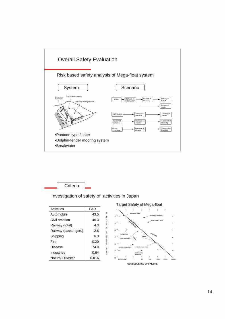
Overall Safety Evaluation
Risk based safety analysis of Mega-float system
System Scenario
BreakwaterDolphin-fender mooring
Very large floating structure
•Pontoon type floater
•Dolphin-fender mooring system•Breakwater
Wave Damage to breakwater
Failure of mooring
Drifting offloater
Earthquake
Accident &Collision
Damage toFloater
Successive flooding
Failure of floater
Damage to mooring
Drifting offloater
Fire & Explosion
Damage toFloater
Successive flooding
Investigation of safety of activities in Japan
0.016Natural Disaster
0.64Industries
74.9Disease
0.20Fire
6.3Shipping
2.6Railway (passengers)
4.3Railway (total)
46.3Civil Aviation
43.5Automobile
FARActivities
Criteria
MERCHANT SHIPPING
MOBILE DRILL RIGSACCEPTABLE
FOUNDATION
OTHER LNG STUDIESESTIMATED U.S. DAMS
COMMERCIAL AVIATION
MINE PIT SLOPES
1
10
10
10
10
10
10
LIVES LOST 1 10 100 1000 10000
CONSEQUENCE OF FAILURE
FIXED DRILL RIGS
DAMS
AN
NU
AL P
RO
BA
BIL
ITY O
F FA
ILU
RE P
f
-1
-2
-3
-4
-5
-6
100000
Allen's Eq.CIRIA
10-7
VLFS
ALARP-Statoil
Target Safety of Mega-float

15
Megafloat Phase1 Experiment
9 units100m x 20m
Experiment
Phase 1
Megafloat Phase2 Experiment
1000m x 60-140m
Phase 2

16
0
0.2
0.4
0.6
0.8
1
1.2
1.4
0 5 10 15 20 25 30 35 40
Wave Period (sec)
Z-D
isp.
Am
p./W
ave
Am
p.[m
/m]
①[cal.]
①[exp.]
②[cal.]
②[exp.]
③[cal.]
③[exp.]
wave
Semisubmersible Type Mega-float (related research)
Frequency response of deflection at bow
1. Development of hydroelastic response analysis program VODAC
2. Verification by model test

17
Wave tank experiment Wind tunnel experiment
Projects after Technological ResearchAssociation of Mega-float
Megafloat Information BaseL200m x B100m x D2m
World Cup Mega-parkL200m x B100m x D2m
Marine Park KumanonadaL120m x B60m x D3m
Uzushio Megafloat NandanL101m x B60m x D3m
Ferry PierL143m x B20m x D3m
Shimizu Port Fishing ParkL143m x B20m x D3m

18
Haneda International Airport New Runway
Haneda International Airport
New Runway
Floating Wind Turbine
80m
12.5m
20m
75m
40m
20m
pontoon semisub spar
coastal type offshore type