overview of physics results from mast - a clean future · overview of physics results from mast b....
TRANSCRIPT

1
Overview of Physics Results from MAST
B. Lloyd1, R.J. Akers
1, F. Alladio
2, S. Allan
1, L.C. Appel
1, M. Barnes
1,3, N.C. Barratt
4,
N. Ben Ayed1, B.N. Breizman
5, M. Cecconello
6, C.D. Challis
1, I.T. Chapman
1, D. Ciric
1,
G. Colyer1, J.W. Connor
1, N.J. Conway
1, M. Cox
1, S.C. Cowley
1, G. Cunningham
1,
A. Darke1, M. De Bock
1(a), E. Delchambre
7, G. De Temmerman
1(b), R.O. Dendy
1, P. Denner
4,
M.D. Driscoll1, B. Dudson
4, D. Dunai
8, M. Dunstan
1, S. Elmore
9, A.R. Field
1, G. Fishpool
1,
S. Freethy4, L. Garzotti
1, K.J. Gibson
4, M.P. Gryaznevich
1, W. Guttenfelder
10(c), J Harrison
1,4,
R.J. Hastie1, N.C. Hawkes
1, T.C. Hender
1, B. Hnat
10, D.F. Howell
1, M-D Hua
11,
A. Hubbard12, G. Huysmans
7, D. Keeling
1, Y.C. Kim
3, A. Kirk
1, Y. Liang
13, M.K. Lilley
14,
M. Lisak14, S. Lisgo
1(d), Y.Q. Liu
1, G.P. Maddison
1, R. Maingi
15, S.J. Manhood
1, R. Martin
1,
G.J. McArdle1, J. McCone
16, H. Meyer
1, C. Michael
1, S. Mordijck
17, T. Morgan
4,
A.W. Morris1, D.G. Muir
1, E. Nardon
1(e), G. Naylor
1, M.R. O’Brien
1, T. O’Gorman
16,
J. Páleník18, A. Patel
1, S.D. Pinches
1, M.N. Price
1, C.M. Roach
1, V. Rozhansky
19,
S. Saarelma1, S.A. Sabbagh
20, A. Saveliev
21, R. Scannell
1, S.E. Sharapov
1, V. Shevchenko
1,
S. Shibaev1, D. Stork
1, J. Storrs
1, W. Suttrop
22, A. Sykes
1, P. Tamain
1(e), D. Taylor
1,
D. Temple11, N. Thomas-Davies
1, A. Thornton
1,4, M.R. Turnyanskiy
1, M. Valovic
1,
R.G.L. Vann4, G. Voss
1, M.J. Walsh
1(d), S.E.V. Warder
1, H.R. Wilson
4, M. Windridge
11,
M Wisse1(f), S. Zoletnik
8 and the MAST and NBI teams.
1EURATOM/CCFE Fusion Association, Culham Science Centre, Abingdon, UK 2Associazione EURATOM-ENEA sulla Fusione, Frascati, Rome, Italy 3Rudolf Peierls Centre for Theoretical Physics, University of Oxford, Oxford, UK. 4University of York, Heslington, York, UK 5Institute for Fusion Studies, University of Texas, Austin, Texas, 78712 USA 6EURATOM-VR Association, Uppsala University, SE-75120 Uppsala, Sweden 7CEA-Cadarache, Association Euratom-CEA, 13108 St Paul-lez-Durance, France 8KFKI-RMKI, Association EURATOM, Pf. 49, H-1525 Budapest, Hungary 9University of Liverpool, Brownlow Hill, Liverpool, UK 10Department of Physics, Warwick University, UK.
11Imperial College of Science, Technology and Medicine, London, UK.
12MIT Plasma Science and Fusion Center, Cambridge, MA 02139, USA
13Association EURATOM-FZ Jülich, Trilateral Euregio Cluster, D-52425 Jülich, Germany
14Chalmers University of Technology, 41296 Göteborg, Sweden
15Oak Ridge National Laboratory, Oak Ridge, USA.
16University College, Cork, Association EURATOM-DCU Ireland.
17University of California-San Diego, 9500 Gilman Dr, La Jolla, California 92093, USA
18Association EURATOM Comenius University, Slovakia
19St. Petersburg State Polytechnical University, St. Petersburg, Russia.
20Dept of Applied Physics and Applied Maths, Columbia University, New York, NY, USA
21A.F. Ioffe Physico-Technical Institute, St. Petersburg, Russia.
22Max-Planck-Institut für Plasmaphysik, EURATOM Association, Garching, Germany
e-mail contact of main author: [email protected]
(a) Present address: Eindhoven University of Technology, Eindhoven, The Netherlands
(b) Present address: FOM Institute Rijnhuizen, Association EURATOM-FOM, Nieuwegein, The Netherlands
(c) Present address: Princeton Plasma Physics Laboratory, PO Box 451, Princeton, NJ, 08543, USA
(d) Present address: ITER Organization, CS 90 046, 13067 St Paul lez Durance Cedex, France
(e) Present address: CEA-Cadarache, Association Euratom-CEA, 13108 St Paul-lez-Durance, France
(f) Present address: Department of Physics, University of Basel, Klingelbergstrasse 82, CH-4056 Basel,
Switzerland

2
Abstract. Major developments on MAST have enabled important advances in support of ITER and the physics
basis of a spherical tokamak (ST) based component test facility (CTF), as well as providing new insight into
underlying tokamak physics. For example, L-H transition studies benefit from high spatial and temporal
resolution measurements of pedestal profile evolution (temperature, density and radial electric field) and in
support of pedestal stability studies the edge current density profile has been inferred from Motional Stark Effect
(MSE) measurements. The influence of the q-profile and E×B flow shear on transport has been studied in MAST
and equilibrium flow shear has been included in gyro-kinetic codes, improving comparisons with the
experimental data. H-modes exhibit a weaker q and stronger collisionality dependence of heat diffusivity than
implied by IPB98(y,2) scaling, which may have important implications for the design of an ST-based CTF. ELM
mitigation, an important issue for ITER, has been demonstrated by applying resonant magnetic perturbations
(RMPs) using both internal and external coils, but full stabilization of type I ELMs has not been observed.
Modelling shows the importance of including the plasma response to the RMP fields. MAST plasmas with q > 1
and weak central magnetic shear regularly exhibit a long-lived saturated ideal internal mode. Measured plasma
braking in the presence of this mode compares well with neoclassical toroidal viscosity theory. In support of
basic physics understanding, high resolution Thomson scattering measurements are providing new insight into
sawtooth crash dynamics and neoclassical tearing mode critical island widths. Retarding Field Analyzer
measurements show elevated ion temperatures in the scrape-off layer of L-mode plasmas and, in the presence of
type I ELMs, ions with energy greater than 500eV are detected 20cm outside the separatrix. Disruption
mitigation by massive gas injection has reduced divertor heat loads by up to 70 per cent.

3
1. Introduction
The Mega Amp Spherical Tokamak (MAST) is designed to study low aspect ratio (R/a ~
0.85m/0.65m ~ 1.3), highly elongated (κ > 2), plasmas (Ip ≤ 1.5MA, Bt ≤ 0.52T) at high ion
and electron temperature. It is equipped with high power neutral beam heating, adaptable
fuelling systems including pellet injection, digital plasma control, error field compensation
coils and a comprehensive range of high resolution diagnostics. The physics programme
comprises three main elements: (i) exploring the long term potential of the spherical tokamak
as a fusion Component Test Facility (CTF) and/or an advanced power plant; (ii) advancing
key tokamak physics for optimal exploitation of ITER and DEMO design optimisation; and
(iii) providing unique insight into underlying tokamak physics. In pursuit of these aims,
MAST capabilities have recently been further enhanced: internal ELM control coils; Toroidal
Alfvén Eigenmode (TAE) excitation system; disruption mitigation system (fast gas valve on
loan from FZ Jülich); divertor science facility (manipulator allowing insertion of material
samples into the divertor); 28GHz gyrotron (on loan from ORNL, USA); multi-chord
motional Stark effect (MSE) diagnostic; upgraded Thomson scattering (TS) system (part
funded by University of York) giving very high spatial and temporal resolution together with
a new triggering system allowing synchronisation to fast plasma events; collimated neutron
emission detector (collaboration with Uppsala University, Sweden); and many other
diagnostic developments including long wavelength infra-red imaging and a retarding field
energy analyzer (on loan from CEA Cadarache). These technical developments have allowed
important advances to be made on a wide range of studies in support of ITER and future STs.
Results are summarised in sections 2 – 6. Future plans, which include major upgrades to
MAST, are summarised in section 7.
2. Plasma Stability
2.1. Macroscopic Stability
Macroscopic stability studies, aided by high resolution diagnostics including MSE, have
allowed improved understanding of performance limiting instabilities in high beta plasmas [1].
For example, MAST plasmas with q > 1 and weakly reversed magnetic shear, or broad low
shear regions, regularly exhibit frequency sweeping n = 1 modes that evolve into a long-lived
mode (LLM). This has been identified as a saturated ideal internal MHD instability, growing
unstable as qmin approaches unity [2]. Higher-n modes become progressively more unstable
(n/m = 1/1, 2/2, 3/3…) at sufficiently small ∆q (= qmin – 1). Theoretical studies have shown
that the stability of the internal kink mode is highly sensitive to variations in the plasma
density and rotation profiles [3,4]. The ideal internal mode results in strong braking of the
core plasma, enhanced fast ion losses and degradation of the energy confinement (Fig. 1).
Once ∆q becomes sufficiently small that the LLM becomes unstable, the enhanced fast ion
losses mean that there are no longer sufficient energetic ions within the core of the plasma to
drive the ‘fishbone’ instabilities and the chirping activity ceases. The measured plasma
braking (by high resolution charge exchange recombination spectroscopy) due to the LLM
compares favourably with neoclassical toroidal viscosity (NTV) theory [5]. External magnetic
perturbations (n = 2) have also been applied in co- and counter-NBI heated plasmas to further
test predictions of NTV theory. Initial analysis, for the counter-NBI case, indicates significant
discrepancy between measured and predicted braking which requires additional modelling to
resolve [1]. MAST plasmas have operated well above the ideal no-wall stability limit and the
plasma response to externally applied non-axisymmetric magnetic fields is being measured to
investigate resistive wall mode (RWM) stability for a range of fast ion distributions (achieved
by varying plasma density). Both rotation and kinetic effects are important and are intricately
related. Calculations for MAST show that the RWM is most unstable at intermediate densities,

4
in qualitative agreement with experimental data. Damping is strongest at low density. At both
low and high density thermal ion stabilisation dominates the kinetic damping of the RWM [1].
The upgraded Thomson scattering (TS) system, with radial resolution ~ 10mm and the
possibility of temporal resolution ≤ 1µs, has enabled detailed analysis of the density and
temperature profiles in and around a neoclassical tearing mode (NTM) island, permitting tests
of models for the critical NTM island width. Initial results show that the observed threshold
island width is larger than the critical width measured assuming finite parallel diffusive
transport [6]. Similarly, high resolution TS measurements during the sawtooth crash have
provided new insight into the crash mechanism [7]. As magnetic reconnection occurs, the
growing magnetic island causes an increase in the electron temperature gradient at the island
boundary layer. The island width grows and the region of increasing temperature gradient
moves into a region of lower magnetic shear triggering a secondary instability, thought to be
responsible for the rapidity of the collapse.
2.2. Current Profile Control
Current profile control is required for optimisation of plasma stability. Off-axis NBCD has
been demonstrated in vertically displaced plasmas in MAST [8]. Anomalous fast ion diffusion
(~ 0.5m2/s) was invoked to explain the observed measurements. Modelling of the effects of
the observed fishbone instabilities, using the non-linear HAGIS code, indicate an effective
fast ion diffusion coefficient consistent with that inferred experimentally [9]. Future studies of
the impact of fast ion diffusion during current profile control experiments will benefit from
installation of a new collimated neutron detector [10] and a fast ion Dα (FIDA) diagnostic.
Current penetration also has an important bearing on plasma stability. The ‘Ohmic’ current
profile evolution during the ramp-up phase of a MAST discharge has been determined from
MSE measurements at the start of neutral beam injection with different NBI start times and
compared with the evolution calculated by TRANSP using the earliest current profile
measurements as input. Observed current penetration is significantly slower than that
calculated by TRANSP using neo-classical resistivity. Further investigation is required to
understand this behaviour which has also been observed in JET [11].
2.3. Fast Particle Instabilities
MAST exhibits a variety of modes excited over a broad range of frequencies from Alfvén
cascade (AC) eigenmodes, toroidal Alfvén eigenmodes (TAE), and chirping modes in the
frequency range 50-150 kHz, to compressional Alfvén eigenmodes (CAE) in the frequency
range 0.4-3.8 MHz, which is approaching the cyclotron frequency of the plasma ions. In spite
of the significant differences in the nature of the modes and in the corresponding excitation
mechanisms, it has been shown that the non-linear evolution of the frequency and amplitude
of these modes (i.e. steady-state saturated amplitude, or bursting behaviour with frequency
sweeping) is determined by the type and strength of the relaxation processes affecting the fast
particles driving the waves [12]. In particular, the disparity between experimental
observations on MAST, in which AE are excited by super-Alfvénic neutral beam ions, and
those on JET using ICRF accelerated fast ions, has been attributed to the role of dynamical
friction (drag), which acts as a relaxation process affecting the resonant particles [13,14] in a
simplified bump-on-tail model. More sophisticated modelling of the influence of drag upon
the evolution of Alfvénic instabilities in general tokamak geometry, and with realistic
distribution functions, has been undertaken with the non-linear drift-kinetic δf code, HAGIS
[15]. These results support the qualitative trends of the earlier bump-on-tail analysis. The
damping of TAE, in the absence of any fast ion drive, is also being studied in MAST through

5
the active excitation of stable modes using an internal set of coils. So far it has proved
difficult to routinely detect the response of such modes however, studies will continue in 2011
with a significantly increased drive capability.
3. Confinement and Transport
3.1. Confinement Scaling
One promising application of the spherical tokamak (ST) is an intense volume neutron source
for testing fusion components [16]. To predict plasma performance in such a Component Test
Facility (CTF), reliable estimates of energy confinement time τΕ are required. H-mode
plasmas in both MAST [17] and NSTX [18] exhibit a slightly weaker scaling of τΕ with Ip and
a much stronger scaling with Bt than given by the IPB98(y,2) scaling. For example, MAST
data indicate that the thermal energy confinement time τΕ,th scales as τΕ,th ∝ Ip0.59Bt1.4.
Transport analysis showed that the strong Bt scaling could be explained by a weaker safety
factor (q) and a stronger collisionality (νe*) dependence of heat diffusivity than implied by
IPB98(y,2). This interpretation has now been confirmed in MAST by dedicated scaling
experiments, in which all dimensionless parameters except the one being studied are held
approximately constant [19]. These studies were conducted in double null (DN) deuterium
plasmas. The results indicated that τΕ,thBt ∝ νe*-0.82 ± 0.1
qeng-0.85 ± 0.2
(Fig. 2), where the
engineering safety factor is given by qeng = 2πa2κBt/(Rµ0Ip), which is quantitatively consistent
with the plasma current and toroidal field scaling measured earlier, assuming gyro-Bohm
scaling [17]. The quoted uncertainties in the exponents represent the standard errors of log-
linear regression analysis. Detailed transport analysis shows that ion transport is close to
neoclassical and local heat transport is dominated by the electrons. Furthermore, for the νe*
scan data set, χe/Bt ∝ νe*(0.5 ÷ 1)
consistent with the global confinement scaling, and the
measured neutron rate increases strongly with toroidal magnetic field, SDD ∝ Bt2.85, in good
agreement with the νe* scaling. In order to match the measured neutron rate in TRANSP
simulations, however, it is necessary to invoke a fast ion diffusion coefficient Dfast ~ 2 – 3
m2/s. The underlying cause of the νe* scaling is still under investigation. Based on experience
in conventional tokamaks, it is likely that the scaling will become weaker as plasmas become
less collisional [20]. The scaling with νe* is particularly important because it is the
dimensionless parameter that exhibits the biggest variation in extrapolating from present STs
to an ST-based CTF.
3.2. Transport Studies
The availability of routine MSE data, together with further developments to Thomson
scattering and charge exchange recombination spectroscopy (CXRS) systems, has enabled the
influence of the q-profile and E×B flow shear on transport to be studied in MAST [21]. Shear
flow suppression of anomalous transport plays an important role in determining the
confinement properties of ST plasmas. Poloidal rotation is measured to be small in MAST,
profiles being consistent with neoclassical predictions, and hence makes only a small
contribution to the net E×B flow shear [22]. However, the strong toroidal rotation, driven by
NBI heating, produces E×B shearing rates sufficient to exceed the growth rate of low-k ion-
scale turbulence. In H-mode plasmas ion heat transport is within a factor 1-3 of the ion neo-
classical level over most of the radius, while the electron transport remains highly anomalous.
In L-mode plasmas, however, the ion transport can far exceed neo-classical levels in the outer
regions but is strongly suppressed by flow shear at mid-radius and, under favourable
conditions can exhibit an internal transport barrier (ITB) with ion transport at the neo-classical
level. As in other tokamaks, ITB formation is favoured by early NBI heating of a low density

6
L-mode discharge, applied during the current ramp to slow current penetration, resulting in
strong toroidal rotation and reversed magnetic shear in the core. With co-NBI, ITBs in the
momentum and ion thermal channels form in the negative shear region just inside qmin (Fig. 3).
Some correlation is found with the magnitude of the normalized toroidal rotation gradient and
the passing of qmin through rational values. There is also evidence that anomalous fast-ion
diffusion, driven by fast particle instabilities, may contribute to local enhancement of the E×B
shearing rate. With counter-NBI, ITBs of greater radial extent form outside qmin due to the
broader profile of E×B flow shear produced by the greater prompt fast-ion loss torque. The
strength of ITBs in MAST is usually limited by coupling of MHD modes which reduce the
rotation gradient and ultimately an internal kink mode (see section 2.1) removes the core flow
shear destroying the ITB when q0 approaches unity. Equilibrium flow shear has been included
in gyro-kinetic codes (e.g. GS2), improving comparisons of linear and non-linear simulations
with results from strongly rotating MAST plasmas [23]. Coupled multi-flux tube simulations
(TRINITY) [24] and global simulations [25] (e.g. using the particle-in-cell code ORB5) with
and without flow shear are also being pursued. For the discharge in Fig. 3, linear stability
analysis with GS2 shows that all electrostatic micro-instabilities are stable in the negative
magnetic shear region in the core, both with and without flow shear. Outside the ITB, in the
region of positive magnetic shear and relatively weak flow shear, electrostatic micro-
instabilities become unstable over a wide range of wave-numbers: at ITG length scales, flow
shear reduces linear growth rates and narrows the spectrum of unstable modes, but flow shear
suppression of ITG modes is incomplete; flow shear has little impact on growth rates at ETG
scales. This is consistent with the observed anomalous electron and ion transport in this
region. Non-linear ORB5 calculations indicate that Ti profiles may be clamped (i.e. ‘stiff’) by
ITG turbulence outside the ITB region [25]. Measurements of the low-k turbulence in such
ITB plasmas using a BES turbulence imaging system newly installed on MAST [26] will in
future allow direct comparison of results from non-linear, ion scale turbulence simulations
with observations in regions where low-k turbulence produces significant anomalous transport
or is fully suppressed.
3.3. Pellet Fuelling
Fuelling and particle confinement investigations have focussed on ‘shallow’ pellet fuelling,
where studies of pellet trajectory, ablation and post-pellet transport benefit from fast visible
imaging and very high spatial and temporal resolution TS measurements, synchronised to the
pellet propagation. Pellets can be injected from either the outboard mid-plane or top high-
field-side of MAST (Fig 4a). Results have been compared with first principles
ablation/deposition codes and confirm the importance of ∇B drift and plasma pre-cooling
effects in determining the pellet penetration depth [27, 28]. Furthermore, high spatial
resolution visible bremsstrahlung imaging of the pellet trajectory reveals discrete structures,
namely striations, that are related to the plasmoids which are responsible for re-deposition of
pellet particles – the critical mechanism for ITER fuelling (Fig. 4b). The striations have a
separation of ~ 4 – 30mm, which is comparable to the ion Larmor radius and indicates that
finite Larmor radius effects may be important for pellet plasmoid dynamics [19]. The
effectiveness of pellet refuelling of H-mode plasmas is also being studied in MAST, including
compatibility with application of resonant magnetic perturbations (RMPs) for ELM control.
The favourable effects of pellet injection for H-mode access and fuelling have been
demonstrated.

7
4. Pedestal Physics & the L-H Transition
H-mode access and properties of the H-mode pedestal have an important influence on
projected ITER performance. In recent MAST experiments, it has been shown that for helium
discharges (with D beams) the H-mode power threshold, PLH, is about 50% higher than for
deuterium and, as observed in other devices, PLH is reduced if the distance between the X-
point and the strike point is shortened [29]. The sensitivity of H-mode access in MAST to
magnetic geometry, especially close to DN, has been reported previously [30]. This sensitivity
may be exploited to control H-mode access [31] allowing, for example, very high resolution
pedestal diagnostics to be synchronised to the H-mode transition. To elucidate the physical
mechanisms underlying the L-H transition, which are not well-understood at present, the
evolution of profiles of Te, ne and Er at the transition have been measured with a time
resolution ∆t < 200µs by Thomson scattering and edge Doppler spectroscopy [29]. Visible
imaging shows that fluctuations are suppressed at the transition on a timescale < 100µs
whereas profile changes occur on a timescale at least 5 times slower, the density pedestal
forming on a faster timescale than the temperature pedestal. Neither the gradient nor the mean
values of Te or Er appear to play a major role in triggering the L-H transition.
Pedestal characteristics have been studied as a function of magnetic configuration and ELM
type [32]. As for most other tokamaks, analysis of pedestal stability relies on calculations of
the edge bootstrap current together with the assumption that Ti = Te. Efforts are underway on
MAST to improve pedestal stability analysis by direct measurement of these quantities [29].
First, a novel technique now provides high resolution Ti profiles in the pedestal [33]. Ti is
deduced from the C6+ temperature using charge exchange recombination of C
6+ by excited D
atoms. At high collisionality, the assumption Ti = Te is found to be a good approximation.
However, at low collisionality, although Ti ≈ Te at the top of the pedestal, the ion temperature
gradient is much shallower than that of electron temperature so that Ti > Te further out. The
data appear to be consistent with modified gyrokinetic theory [34] which requires ρipol∇(lnTi)
<< 1 in the banana regime, where ρipol is the poloidal ion Larmor radius. Second, the
evolution of the edge current density profile has been determined (with 2ms resolution) using
MSE, a measurement made possible due to the large magnetic field pitch angle at the edge of
an ST plasma [35]. Radial electric field corrections are included, from edge Doppler
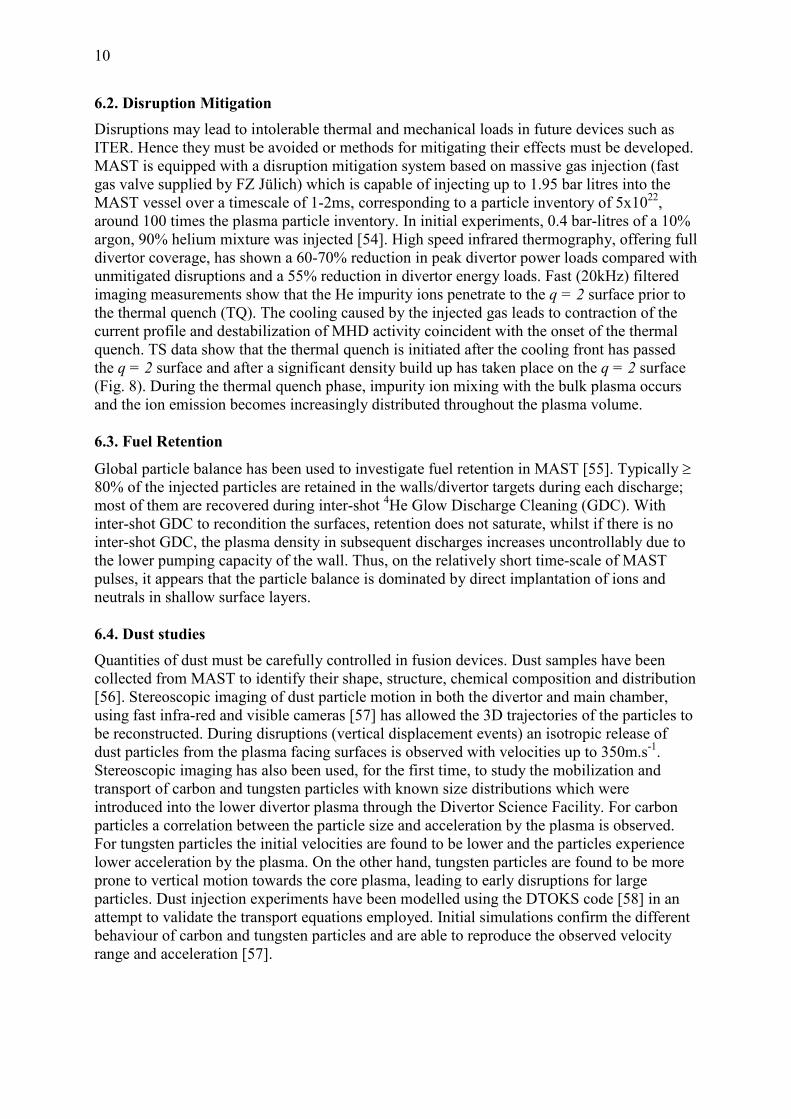
spectroscopy measurements, and are small. As expected, the measured edge current density in
H-mode is significantly greater than that in L-mode. Measured H-mode current density
profiles are compared with calculations of the neo-classical bootstrap current in Fig. 5, just
after an ELM and later in the ELM free period. The calculated bootstrap current density
appears to be somewhat smaller than that measured, with a narrower profile, the difference
being more pronounced just after the ELM. At the time of the type I ELM, ELITE
calculations show the discharge to be close to the ballooning stability boundary. Edge current
density evolution may also be inferred from electron Bernstein wave emission [36, 37]. Initial
measurements [38] indicate large variation in magnetic field line tilt angle over a very small
region (≤ 2cm) close to the LCFS, consistent with a local bi-directional radial current
structure. Further investigations are planned using a new array of up to 37 antennas to image
the electron Bernstein wave emission.
5. ELM control
To avoid damage to in-vessel components in future devices such as ITER, a mechanism to
reduce the size of type I ELMs is required. One such mechanism relies on perturbing the
magnetic field in the edge plasma region, enhancing transport to keep the edge pressure
gradient below the critical value that would trigger an ELM, while still maintaining an edge

8
transport barrier. This technique of Resonant Magnetic Perturbations (RMPs) has been
successfully employed on DIII-D [39], where complete ELM suppression has been observed.
A set of in-vessel ELM control coils consisting of two rows of six coils each, one above and
one below the mid- plane, similar to the DIII-D I-coils, has been installed in MAST [40].
When n = 3 RMPs are applied to MAST L-mode discharges clear resonant effects are
observed, namely density pump-out together with changes in edge fluctuation characteristics,
in the edge radial electric field profile and in the perpendicular and parallel flows [41, 42].
The pump-out is accompanied by a splitting of both the particle and heat flux to the divertor
strike points, indicating that RMP penetration takes place [43]. The magnitude of the pump-
out is correlated with the magnitude of the resonant component of the applied field rather than
the width of the stochastic region produced at the edge of the plasma. The radial electric field
profile flattens when the RMPs are applied, leading to an increase inside the separatrix and a
decrease in the SOL. This change is consistent with what is expected from theories based on
the establishment of a stochastic layer. Given that the pump-out and these other phenomena
appear to require the same current threshold in the RMP coils, it seems likely that there is a
modification of the turbulent transport level. This is in agreement with results from B2SOLPS
modelling which show that the transport coefficients have to be increased in order to match
the observed pump out and changes in electric field [44, 45].
In H-mode plasmas just above the L-H transition threshold, the application of RMPs seems
equivalent to a small decrease in input power. For example, more frequent ELMs can be
triggered in a type III ELMing discharge and type III ELMs can be triggered in an ELM free
discharge. In discharges with type I ELMs, little effect was observed initially, despite the fact
that vacuum modelling (ERGOS) showed that the Chirikov parameter was greater than 1 over
a wide radial extent, i.e. there was a wide stochastic region greater than that correlated with
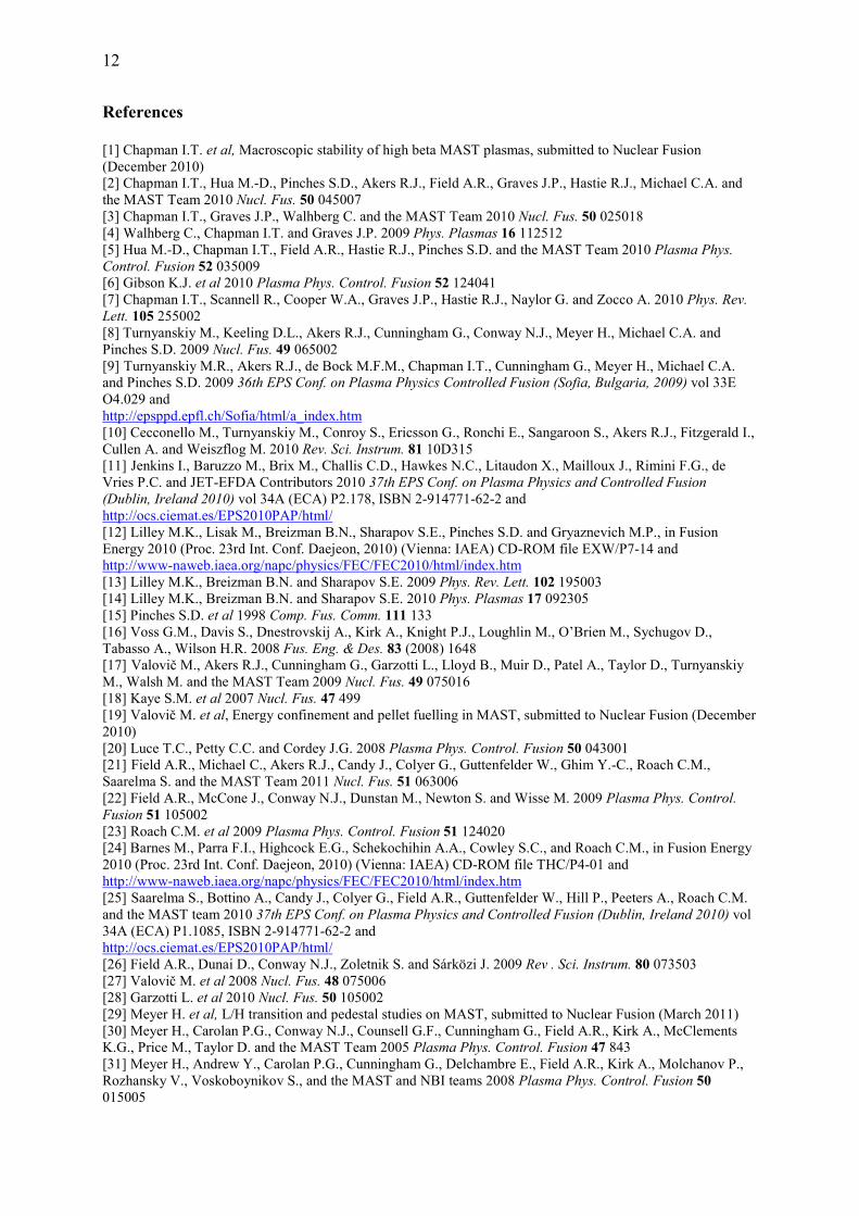
ELM suppression in DIII-D. However, following careful adjustment of q95 in these type I
ELMing discharges, RMPs were observed to increase the ELM frequency (fELM) by a factor
of 5 and decrease the energy loss per ELM (∆WELM) from a mean value of ~5kJ to ~ 1kJ i.e.
consistent with ∆WELM.fELM ~ constant (Fig. 6). This effect on the ELMs is not correlated
with the width of the region for which the (vacuum field) Chirikov parameter is greater than 1
but may be correlated with the size of the resonant component of the applied field. Realistic
modelling should include the response of the plasma to the RMP fields, in addition to the
vacuum field produced by the coils. The linear and nonlinear response of the plasma to RMP
fields, has been investigated using the MARS-F/K codes and the BOUT++ code, respectively
[46]. The resonant spectrum of the vacuum field produced by the RMP coils is significantly
modified near the edge of the plasma and the field amplitude near rational surfaces is
significantly reduced. Calculations also show that rapid toroidal plasma rotation, as observed
in MAST H-mode plasmas with type I ELMs, can provide efficient shielding. Since in ITER
it will be necessary to suppress the first large type I ELM, the RMPs may need to be applied
before the L-H transition, which may affect the power required to access H-mode. On MAST
the application of n=3 RMPs before the L-H transition can either suppress the L-H transition
entirely or significantly delay it. For the cases studied, it was necessary to increase the beam
power by 30 - 40% to re-establish the L-H transition. A similar increase in L-H transition
power, above a certain perturbation strength, is also observed on DIII-D and NSTX [47]. The
implications of this for ITER still need to be determined, but it is likely that due to the low
ELM frequency the rise time of the coils will be sufficiently fast such that they can be applied
after the L-H transition but before the first ELM.

9
6. Exhaust Physics
6.1. Divertor Heat Load Studies & SOL Ti measurements
Quantification of heat loads (magnitude and spatial distribution) on plasma-facing
components is important for the design of future devices as it impacts on component lifetime.
Long-wave infrared (LWIR) and medium-wave infrared (MWIR) cameras have been used to
measure heat load asymmetries (in/out and up/down) for a variety of magnetic configurations,
with NBI power up to 3 MW [48]. As expected, the LWIR system is less sensitive to
disturbances from hot spots or surface layers [49]. Good power accounting was obtained in L-
mode discharges with ~ 100% of the power flowing to the SOL (radiation subtracted)
reaching the divertor. The in/out asymmetry was found to be very sensitive to drsep, the
distance between the two separatrices at the outboard mid-plane. In all cases, most of the
energy arriving in the SOL goes to the outer divertor, confirming earlier probe data [50]. For
double null (DN) discharges with drsep ~ 0, the observed ratio of power arriving at the outer
strike-points to that at the inboard strike points lies in the range 20–40. Heat load asymmetries
have also been studied during and between type-I ELMs for both DN and lower single null
(SN) discharges. During DN discharges, most of the energy flows to the outer divertor and
during ELMs, filamentary structures are observed at the outer divertor while the heat flux
profile at the inner divertor remains largely unchanged. Although more energy arrives at the
inner target in SN discharges, the largest amount of ELM energy is still deposited on the outer
target and filamentary structures are observed at both the inner and outer divertors.
Langmuir probe data are widely used to infer energy fluxes to divertor and plasma facing
components. The assumption Ti = Te is usually deployed to infer the electron density or power
deposition from the probe data. Ion temperature measurements are important to reduce
uncertainties in these derived parameters and because the energy of the ions determines the
physical sputtering rates from plasma facing materials. Initial ion energy measurements have
been obtained in the MAST outboard mid-plane SOL using a Retarding Field Analyzer (RFA)
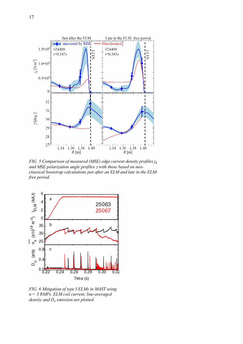
supplied by CEA Cadarache [51]. Example data are plotted in Fig. 7 for a beam heated lower
SN L-mode discharge. The measurements in Fig. 7 are calculated to underestimate the
unperturbed ion temperature by a factor 1 – 1.3 due to plasma flow effects. Accounting for
this, it was concluded that for a range of L-mode discharges Ti/Te = 1 – 2.6 in the MAST
SOL. These results are quantitatively consistent with previous power balance studies in
MAST [50] which showed that the total power calculated from Langmuir probe
measurements at the divertor targets is equal to the power transported out of the confined
plasma assuming Ti = Te. Using the OSM2 transport model, this ratio can then be extrapolated
to Ti/Te = 2 – 2.5 at the mid-plane [52], in reasonable agreement with RFA measurements.
First measurements have also been obtained in H-mode, with ion energies in excess of 500eV
being detected 19cm away from the separatrix during saw-tooth triggered type-I ELMs.
Steady-state heat loads on plasma facing components may be reduced by operating with a
‘detached’ divertor, where plasma pressure and energy is dissipated along the divertor leg.
Partial detachment can be achieved in MAST L-mode discharges (PNBI = 1MW) with
localized deuterium puffing into the lower inner divertor leg [53]. High resolution
spectroscopic data from MAST will be used to constrain interpretive modelling efforts to
ascertain the plasma conditions within the recombining region, and yield insights into the
physical mechanisms that give rise to detachment.
10
6.2. Disruption Mitigation
Disruptions may lead to intolerable thermal and mechanical loads in future devices such as
ITER. Hence they must be avoided or methods for mitigating their effects must be developed.
MAST is equipped with a disruption mitigation system based on massive gas injection (fast
gas valve supplied by FZ Jülich) which is capable of injecting up to 1.95 bar litres into the
MAST vessel over a timescale of 1-2ms, corresponding to a particle inventory of 5x10²²,
around 100 times the plasma particle inventory. In initial experiments, 0.4 bar-litres of a 10%
argon, 90% helium mixture was injected [54]. High speed infrared thermography, offering full
divertor coverage, has shown a 60-70% reduction in peak divertor power loads compared with
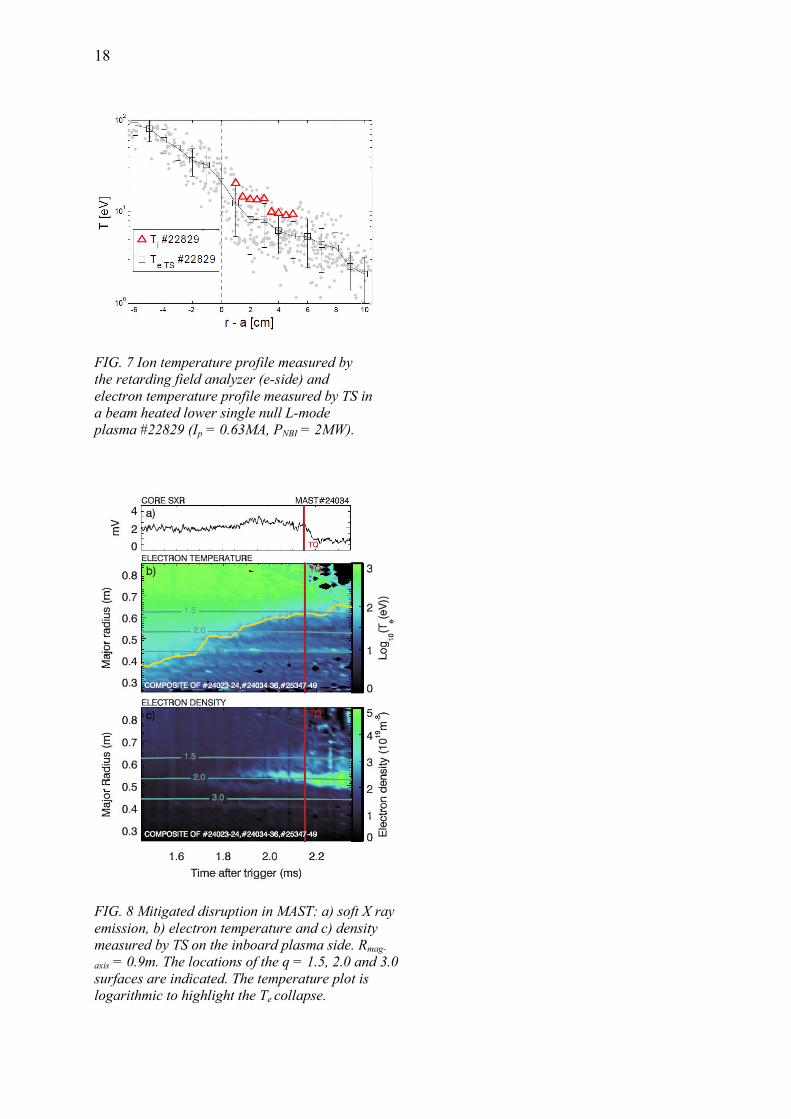
unmitigated disruptions and a 55% reduction in divertor energy loads. Fast (20kHz) filtered
imaging measurements show that the He impurity ions penetrate to the q = 2 surface prior to
the thermal quench (TQ). The cooling caused by the injected gas leads to contraction of the
current profile and destabilization of MHD activity coincident with the onset of the thermal
quench. TS data show that the thermal quench is initiated after the cooling front has passed
the q = 2 surface and after a significant density build up has taken place on the q = 2 surface
(Fig. 8). During the thermal quench phase, impurity ion mixing with the bulk plasma occurs
and the ion emission becomes increasingly distributed throughout the plasma volume.
6.3. Fuel Retention
Global particle balance has been used to investigate fuel retention in MAST [55]. Typically ≥
80% of the injected particles are retained in the walls/divertor targets during each discharge;
most of them are recovered during inter-shot 4He Glow Discharge Cleaning (GDC). With
inter-shot GDC to recondition the surfaces, retention does not saturate, whilst if there is no
inter-shot GDC, the plasma density in subsequent discharges increases uncontrollably due to
the lower pumping capacity of the wall. Thus, on the relatively short time-scale of MAST
pulses, it appears that the particle balance is dominated by direct implantation of ions and
neutrals in shallow surface layers.
6.4. Dust studies
Quantities of dust must be carefully controlled in fusion devices. Dust samples have been
collected from MAST to identify their shape, structure, chemical composition and distribution
[56]. Stereoscopic imaging of dust particle motion in both the divertor and main chamber,
using fast infra-red and visible cameras [57] has allowed the 3D trajectories of the particles to
be reconstructed. During disruptions (vertical displacement events) an isotropic release of
dust particles from the plasma facing surfaces is observed with velocities up to 350m.s-1.
Stereoscopic imaging has also been used, for the first time, to study the mobilization and
transport of carbon and tungsten particles with known size distributions which were
introduced into the lower divertor plasma through the Divertor Science Facility. For carbon
particles a correlation between the particle size and acceleration by the plasma is observed.
For tungsten particles the initial velocities are found to be lower and the particles experience
lower acceleration by the plasma. On the other hand, tungsten particles are found to be more
prone to vertical motion towards the core plasma, leading to early disruptions for large
particles. Dust injection experiments have been modelled using the DTOKS code [58] in an
attempt to validate the transport equations employed. Initial simulations confirm the different
behaviour of carbon and tungsten particles and are able to reproduce the observed velocity
range and acceleration [57].

11
7. Future Plans
New capabilities that will be available in 2011 include additional ELM control coils, a 2D
beam emission spectroscopy system, a fast ion Dα system (FIDA), a 4-chord collimated
neutron detector, an electron Bernstein wave imaging system, new retarding field energy
analyzers and improvements to the edge Doppler spectroscopy system enabling high
frequency fluctuation measurements (≥ 50kHz). These developments will significantly
enhance our capabilities to study ELM control, turbulent transport, fast ion behaviour and
pedestal physics. In the longer term, an upgrade to MAST (MAST-U) has been designed and
the first major stage is now to be implemented [59]. The initial upgrade will incorporate and
test a closed cryo-pumped divertor configuration based on the super-X concept [60] and
enable assessment of dominantly non-inductive operation at the Ip ≥ 1MA level for several
current diffusion times. A new centre column and toroidal field power supply will give
increased solenoid flux and toroidal magnetic field whilst new poloidal field coils will allow
increased plasma shaping. The NBI power will be raised initially to 7.5MW, with increased
off-axis current drive capability. Together these improvements will significantly extend the
operating space of MAST, particularly towards lower normalized collisionality. This should
enable substantial progress on the most critical physics issues for an ST-based CTF and
further strengthen MAST contributions to ITER- and DEMO-relevant physics.
Acknowledgements
This work was part-funded by the RCUK Energy Programme under grant EP/I501045 and the European
Communities under the contract of Association between EURATOM and CCFE. The views and opinions
expressed herein do not necessarily reflect those of the European Commission. Part of the work was carried out
within the framework of the European Fusion Development Agreement.
12
References
[1] Chapman I.T. et al, Macroscopic stability of high beta MAST plasmas, submitted to Nuclear Fusion
(December 2010)
[2] Chapman I.T., Hua M.-D., Pinches S.D., Akers R.J., Field A.R., Graves J.P., Hastie R.J., Michael C.A. and
the MAST Team 2010 Nucl. Fus. 50 045007
[3] Chapman I.T., Graves J.P., Walhberg C. and the MAST Team 2010 Nucl. Fus. 50 025018
[4] Walhberg C., Chapman I.T. and Graves J.P. 2009 Phys. Plasmas 16 112512
[5] Hua M.-D., Chapman I.T., Field A.R., Hastie R.J., Pinches S.D. and the MAST Team 2010 Plasma Phys.
Control. Fusion 52 035009
[6] Gibson K.J. et al 2010 Plasma Phys. Control. Fusion 52 124041
[7] Chapman I.T., Scannell R., Cooper W.A., Graves J.P., Hastie R.J., Naylor G. and Zocco A. 2010 Phys. Rev.
Lett. 105 255002
[8] Turnyanskiy M., Keeling D.L., Akers R.J., Cunningham G., Conway N.J., Meyer H., Michael C.A. and
Pinches S.D. 2009 Nucl. Fus. 49 065002
[9] Turnyanskiy M.R., Akers R.J., de Bock M.F.M., Chapman I.T., Cunningham G., Meyer H., Michael C.A. and Pinches S.D. 2009 36th EPS Conf. on Plasma Physics Controlled Fusion (Sofia, Bulgaria, 2009) vol 33E
O4.029 and
http://epsppd.epfl.ch/Sofia/html/a_index.htm
[10] Cecconello M., Turnyanskiy M., Conroy S., Ericsson G., Ronchi E., Sangaroon S., Akers R.J., Fitzgerald I.,
Cullen A. and Weiszflog M. 2010 Rev. Sci. Instrum. 81 10D315
[11] Jenkins I., Baruzzo M., Brix M., Challis C.D., Hawkes N.C., Litaudon X., Mailloux J., Rimini F.G., de Vries P.C. and JET-EFDA Contributors 2010 37th EPS Conf. on Plasma Physics and Controlled Fusion
(Dublin, Ireland 2010) vol 34A (ECA) P2.178, ISBN 2-914771-62-2 and
http://ocs.ciemat.es/EPS2010PAP/html/
[12] Lilley M.K., Lisak M., Breizman B.N., Sharapov S.E., Pinches S.D. and Gryaznevich M.P., in Fusion
Energy 2010 (Proc. 23rd Int. Conf. Daejeon, 2010) (Vienna: IAEA) CD-ROM file EXW/P7-14 and
http://www-naweb.iaea.org/napc/physics/FEC/FEC2010/html/index.htm
[13] Lilley M.K., Breizman B.N. and Sharapov S.E. 2009 Phys. Rev. Lett. 102 195003
[14] Lilley M.K., Breizman B.N. and Sharapov S.E. 2010 Phys. Plasmas 17 092305
[15] Pinches S.D. et al 1998 Comp. Fus. Comm. 111 133
[16] Voss G.M., Davis S., Dnestrovskij A., Kirk A., Knight P.J., Loughlin M., O’Brien M., Sychugov D.,
Tabasso A., Wilson H.R. 2008 Fus. Eng. & Des. 83 (2008) 1648
[17] Valovič M., Akers R.J., Cunningham G., Garzotti L., Lloyd B., Muir D., Patel A., Taylor D., Turnyanskiy M., Walsh M. and the MAST Team 2009 Nucl. Fus. 49 075016
[18] Kaye S.M. et al 2007 Nucl. Fus. 47 499
[19] Valovič M. et al, Energy confinement and pellet fuelling in MAST, submitted to Nuclear Fusion (December
2010)
[20] Luce T.C., Petty C.C. and Cordey J.G. 2008 Plasma Phys. Control. Fusion 50 043001
[21] Field A.R., Michael C., Akers R.J., Candy J., Colyer G., Guttenfelder W., Ghim Y.-C., Roach C.M., Saarelma S. and the MAST Team 2011 Nucl. Fus. 51 063006
[22] Field A.R., McCone J., Conway N.J., Dunstan M., Newton S. and Wisse M. 2009 Plasma Phys. Control.
Fusion 51 105002
[23] Roach C.M. et al 2009 Plasma Phys. Control. Fusion 51 124020
[24] Barnes M., Parra F.I., Highcock E.G., Schekochihin A.A., Cowley S.C., and Roach C.M., in Fusion Energy
2010 (Proc. 23rd Int. Conf. Daejeon, 2010) (Vienna: IAEA) CD-ROM file THC/P4-01 and
http://www-naweb.iaea.org/napc/physics/FEC/FEC2010/html/index.htm
[25] Saarelma S., Bottino A., Candy J., Colyer G., Field A.R., Guttenfelder W., Hill P., Peeters A., Roach C.M. and the MAST team 2010 37th EPS Conf. on Plasma Physics and Controlled Fusion (Dublin, Ireland 2010) vol
34A (ECA) P1.1085, ISBN 2-914771-62-2 and
http://ocs.ciemat.es/EPS2010PAP/html/
[26] Field A.R., Dunai D., Conway N.J., Zoletnik S. and Sárközi J. 2009 Rev . Sci. Instrum. 80 073503
[27] Valovič M. et al 2008 Nucl. Fus. 48 075006
[28] Garzotti L. et al 2010 Nucl. Fus. 50 105002
[29] Meyer H. et al, L/H transition and pedestal studies on MAST, submitted to Nuclear Fusion (March 2011)
[30] Meyer H., Carolan P.G., Conway N.J., Counsell G.F., Cunningham G., Field A.R., Kirk A., McClements
K.G., Price M., Taylor D. and the MAST Team 2005 Plasma Phys. Control. Fusion 47 843
[31] Meyer H., Andrew Y., Carolan P.G., Cunningham G., Delchambre E., Field A.R., Kirk A., Molchanov P.,
Rozhansky V., Voskoboynikov S., and the MAST and NBI teams 2008 Plasma Phys. Control. Fusion 50
015005

13
[32] Kirk A., O'Gorman T., Saarelma S., Scannell R., Wilson H.R. and the MAST Team 2009 Plasma Phys.
Control. Fusion 51 065016
[33] Morgan T.W., Meyer H., Temple D. and Tallents G.J. 2010 37th EPS Conf. on Plasma Physics and Controlled Fusion (Dublin, Ireland 2010) vol 34A (ECA) P5.122, ISBN 2-914771-62-2 and
http://ocs.ciemat.es/EPS2010PAP/html/
[34] Kagan G. and Catto P.J. 2008 Plasma Phys. Control. Fusion 50 085010
[35] De Bock M.F.M., Saarelma S., Temple D., Conway N.J., Kirk A., Meyer H., Michael C.A. and the MAST team 2010 37th EPS Conf. on Plasma Physics and Controlled Fusion (Dublin, Ireland 2010) vol 34A (ECA)
O2.107, ISBN 2-914771-62-2 and
http://ocs.ciemat.es/EPS2010PAP/html/
[36] Shevchenko V.F. 2000 Plasma Physics Reports 26 1000
[37] Volpe F. 2010 Rev. Sci. Instrum. 81 10D905
[38] Shevchenko V.F., De Bock M., Freethy S.J., Saveliev A.N. and Vann R.G.L. 2011 Fusion Science &
Technology 59 663
[39] Evans T.E. et al 2004 Phys. Rev. Lett. 92 235003
[40] Kirk A. et al 2010 Nucl. Fus. 50 034008
[41] Kirk A., Nardon E., Tamain P., Denner P., Liu Y.Q., Meyer H., Mordijck S., Temple D. and the MAST
team, in Fusion Energy 2010 (Proc. 23rd Int. Conf. Daejeon, 2010) (Vienna: IAEA) CD-ROM file EXD/8-2 and
http://www-naweb.iaea.org/napc/physics/FEC/FEC2010/html/index.htm
[42] Tamain P., Kirk A., Nardon E., Dudson B., Hnat B. and the MAST Team 2010 Plasma Phys. Control.
Fusion 52 075017
[43] Nardon E. et al 2009 Plasma Phys. Control. Fusion 51 124010
[44] Rozhansky V., Kaveeva E., Molchanov P., Veselova I., Voskoboynikov S., Coster D., Kirk A., Lisgo S. and
Nardon E. 2010 Nucl. Fus. 50 034005
[45] Rozhansky V. et al, Modeling of the Edge Plasma of MAST in the Presence of Resonant Magnetic
Perturbations, submitted to Nuclear Fusion (January 2011)
[46] Liu Y.Q., Dudson B.D., Gribov Y., Gryaznevich M.P., Hender T.C., Kirk A., Nardon E., Umansky M.V.,
Wilson H.R. and Xu X.Q., in Fusion Energy 2010 (Proc. 23rd Int. Conf. Daejeon, 2010) (Vienna: IAEA) CD-
ROM file THS/P5-10 and
http://www-naweb.iaea.org/napc/physics/FEC/FEC2010/html/index.htm
[47] Fenstermacher M.E. et al, in Fusion Energy 2010 (Proc. 23rd Int. Conf. Daejeon, 2010) (Vienna: IAEA)
CD-ROM file TR/P1-30 and
http://www-naweb.iaea.org/napc/physics/FEC/FEC2010/html/index.htm
[48] De Temmerman G., Delchambre E., Dowling J., Kirk A., Lisgo S. and Tamain P. 2010 Plasma Phys.
Control. Fusion 52 095005
[49] Delchambre E., Counsell G. and Kirk A. 2009 Plasma Phys. Control. Fusion 51 055012
[50] Kirk A. et al 2004 Plasma Phys. Control. Fusion 46 551
[51] Tamain P., Kočan M., Gunn J., Kirk A., Pascal J.-Y. and Price M. 2011 J. Nucl. Mater., in press doi:
10.1016/j.jnucmat.2010.11.078
[52] Kirk A., Counsell G.F., Fundamenski W., Ahn J.-W., Taylor D., Walsh M.J., Yang Y. and the MAST Team
2004 Plasma Phys. Control. Fusion 46 1591
[53] Harrison J.R., Lisgo S.W., Gibson K.J., Tamain P., Dowling J. and the MAST Team 2011 J. Nucl. Mater.,
in press doi: 10.1016/j.jnucmat.2010.12.226
[54] Thornton A.J., Gibson K.J., Harrison J.R., Kirk A., Lisgo S.W., Lehnen M., Martin R., Naylor G., Scannell
R., Cullen A. and the MAST Team 2011 J. Nucl. Mater., in press doi:10.1016/j.jnucmat.2010.10.029
[55] Huang J., Lisgo S., Maddison G. and the MAST Team 2010 Plasma Phys. Control. Fusion 52 075012
[56] Arnas C., Pardanaud C., Martin C., Roubin P., De Temmerman G. and Counsell G.F. 2010 J. Nucl. Mater.
401 130
[57] De Temmerman G., Bacharis M., Dowling J. and Lisgo S. 2010 Nucl. Fus. 50 105012
[58] Bacharis M., Coppins M. and Allen J.E. 2010 Phys. Plasmas 17 042505
[59] Stork D. et al, in Fusion Energy 2010 (Proc. 23rd Int. Conf. Daejeon, 2010) (Vienna: IAEA) CD-ROM file
ICC/P5-06 and
http://www-naweb.iaea.org/napc/physics/FEC/FEC2010/html/index.htm
[60] Valanju P.M., Kotschenreuther M., Mahajan S.M. and Canik J. 2009 Phys. Plasmas 16 056110

14
Figures
0.10 0.15 0.20 0.25 0.30 0.35time [s]
0.0
0.1
0.2
0.3
ξ(n=
2)/ξ
(n=1
)
0
10
20
30
40
50
τ E [m
s]
0
50
100
150
200
v ϕ [k
m.s
−1]
0.90m 1.00m 1.10m 1.20m 1.30m
0
20
40
60
f MH
D [k
Hz]
MAST shot #21781
(a)
(b)
(c)
(d)
FIG 1. (a) Spectrogram of outboard magnetic probe measurements for a MAST plasma featuring
the LLM, (b) energy confinement time (TRANSP), (c) plasma velocity at different major radius
positions (magnetic axis at R=0.95 m), (d) amplitude ratio of the n=2 component to the n =1
component for the LLM, (e) the growth rates (normalized to the Alfvén frequency at the magnetic
axis) of the n = 1 (red triangles), n= 2 (blue squares), and n= 3 (green diamonds) modes as a
function of ∆q ( = qmin – 1) at mode onset (MISHKA). Inset shows q profile at 0.22s
FIG. 2. Variation of thermal energy confinement time with electron collisionality and safety
factor. Collisionality data are shown for two different plasma shapes (� κ = 2.0, � κ = 1.7) and the vertical bars indicate the magnitude of correction due to variations in normalized Larmor
radius over the collisionality scan.

15
FIG. 3 Evolution of magnetic shear and normalized gradients of ion
temperature and toroidal rotation for an L-mode discharge with co-
NBI which forms an ITB. The green contours indicate rational q
values and the blue contour denotes qmin. LTi and Lω are the gradient
scale lengths of ion temperature and toroidal rotation respectively. ρs is the ion Larmor radius at the sound speed.

16
FIG. 4 (a) Pellet injection geometry in MAST. (b) Pellet image in narrow band (λ0 = 457.25 nm, λFWHM = 2.43 nm) visible bremsstrahlung for top high-field-side launch. The exposure time is 7 ms. The superimposed trace shows the emission intensity along the pellet trajectory.
17
FIG. 5 Comparison of measured (MSE) edge current density profiles jφ
and MSE polarization angle profiles γ with those based on neo-classical bootstrap calculations just after an ELM and late in the ELM-
free period.
FIG. 6 Mitigation of type I ELMs in MAST using
n = 3 RMPs. ELM coil current, line-averaged
density and Dα emission are plotted.
18
FIG. 7 Ion temperature profile measured by
the retarding field analyzer (e-side) and
electron temperature profile measured by TS in
a beam heated lower single null L-mode
plasma #22829 (Ip = 0.63MA, PNBI = 2MW).
FIG. 8 Mitigated disruption in MAST: a) soft X ray
emission, b) electron temperature and c) density
measured by TS on the inboard plasma side. Rmag-
axis = 0.9m. The locations of the q = 1.5, 2.0 and 3.0
surfaces are indicated. The temperature plot is
logarithmic to highlight the Te collapse.