overview of switchgear: overview of - on-campus
TRANSCRIPT

Overview of
Safety
Instrumented
Systems
Overview of Switchgear: Network Context Historical Perspective Rating and Specification

Safe Operation and Maintenance of
Circuit Breakers and Switchgear

WHO ARE WE? IDC Technologies is internationally acknowledged as the premier provider of practical, technical training for engineers and technicians. We specialize in the fields of electrical systems, industrial data communications, telecommunications, automation and control, mechanical engineering, chemical and civil engineering, and are continually adding to our portfolio of over 60 different workshops. Our instructors are highly respected in their fields of expertise and in the last ten years have trained over 200,000 engineers, scientists and technicians. With offices conveniently located worldwide, IDC Technologies has an enthusiastic team of professional engineers, technicians and support staff who are committed to providing the highest level of training and consultancy. TECHNICAL WORKSHOPS TRAINING THAT WORKS We deliver engineering and technology training that will maximize your business goals. In today’s competitive environment, you require training that will help you and your organization to achieve its goals and produce a large return on investment. With our ‘training that works’ objective you and your organization will:
• Get job-related skills that you need to achieve your business goals • Improve the operation and design of your equipment and plant • Improve your troubleshooting abilities • Sharpen your competitive edge • Boost morale and retain valuable staff • Save time and money
EXPERT INSTRUCTORS We search the world for good quality instructors who have three outstanding attributes:
1. Expert knowledge and experience – of the course topic 2. Superb training abilities – to ensure the know-how is transferred effectively and quickly to you in
a practical, hands-on way 3. Listening skills – they listen carefully to the needs of the participants and want to ensure that you
benefit from the experience. Each and every instructor is evaluated by the delegates and we assess the presentation after every class to ensure that the instructor stays on track in presenting outstanding courses. HANDS-ON APPROACH TO TRAINING All IDC Technologies workshops include practical, hands-on sessions where the delegates are given the opportunity to apply in practice the theory they have learnt. REFERENCE MATERIALS A fully illustrated workshop book with hundreds of pages of tables, charts, figures and handy hints, plus considerable reference material is provided FREE of charge to each delegate. ACCREDITATION AND CONTINUING EDUCATION Satisfactory completion of all IDC workshops satisfies the requirements of the International Association for Continuing Education and Training for the award of 1.4 Continuing Education Units. IDC workshops also satisfy criteria for Continuing Professional Development according to the requirements of the Institution of Electrical Engineers and Institution of Measurement and Control in the UK, Institution of Engineers in Australia, Institution of Engineers New Zealand, and others.
THIS BOOK WAS DEVELOPED BY IDC TECHNOLOGIES

CERTIFICATE OF ATTENDANCE Each delegate receives a Certificate of Attendance documenting their experience. 100% MONEY BACK GUARANTEE IDC Technologies’ engineers have put considerable time and experience into ensuring that you gain maximum value from each workshop. If by lunchtime on the first day you decide that the workshop is not appropriate for your requirements, please let us know so that we can arrange a 100% refund of your fee. ONSITE WORKSHOPS All IDC Technologies Training Workshops are available on an on-site basis, presented at the venue of your choice, saving delegates travel time and expenses, thus providing your company with even greater savings. OFFICE LOCATIONS
AUSTRALIA • CANADA • INDIA • IRELAND • MALAYSIA • NEW ZEALAND • POLAND • SINGAPORE • SOUTH AFRICA • UNITED KINGDOM • UNITED STATES
[email protected] www.idc-online.com
Visit our website for FREE Pocket Guides IDC Technologies produce a set of 6 Pocket Guides used by
thousands of engineers and technicians worldwide. Vol. 1 – ELECTRONICS Vol. 4 – INSTRUMENTATION Vol. 2 – ELECTRICAL Vol. 5 – FORMULAE & CONVERSIONS Vol. 3 – COMMUNICATIONS Vol. 6 – INDUSTRIAL AUTOMATION
To download a FREE copy of these internationally best selling pocket guides go to:
www.idc-online.com/downloads/


Presents
Safe Operation and Maintenance of
Circuit Breakers and Switchgear
Revision 6.1
Website: www.idc-online.com E-mail: [email protected]

IDC Technologies Pty Ltd PO Box 1093, West Perth, Western Australia 6872 Offices in Australia, New Zealand, Singapore, United Kingdom, Ireland, Malaysia, Poland, United States of America, Canada, South Africa and India Copyright © IDC Technologies 2008. All rights reserved. First published 2008. All rights to this publication, associated software and workshop are reserved. No part of this publication may be reproduced, stored in a retrieval system or transmitted in any form or by any means electronic, mechanical, photocopying, recording or otherwise without the prior written permission of the publisher. All enquiries should be made to the publisher at the address above. ISBN: 978-1-921007-37-8
Disclaimer Whilst all reasonable care has been taken to ensure that the descriptions, opinions, programs, listings, software and diagrams are accurate and workable, IDC Technologies do not accept any legal responsibility or liability to any person, organization or other entity for any direct loss, consequential loss or damage, however caused, that may be suffered as a result of the use of this publication or the associated workshop and software.
In case of any uncertainty, we recommend that you contact IDC Technologies for clarification or assistance.
Trademarks All logos and trademarks belong to, and are copyrighted to, their companies respectively. Acknowledgements IDC Technologies expresses its sincere thanks to all those engineers and technicians on our training workshops who freely made available their expertise in preparing this manual.

Contents 1 Switchgear in a Network Context 1
1.1 Single line diagrams 2 1.2 Active and passive components 2 1.3 Circuit breaker utilization 2 1.4 Forms of medium voltage switchgear 3 1.5 Basic circuit breaker design 5 1.6 Auto reclosing 8
2 Switchgear in an Historic Perspective 13 2.1 Plain break oil circuit breakers 13 2.2 Small oil volume circuit breakers 18 2.3 Air blast circuit breakers 19 2.4 Operating mechanisms 23 2.5 SF6 and vacuum circuit breakers 23 2.6 Puffer type SF6 circuit breakers 25
3 Switchgear Rating and Specification 29 3.1 Standards and factors affecting circuit breaker selection 29 3.2 Rated voltage Ur 30 3.3 Rated insulation level 31 3.4 Rated short time withstand current (Ik) 33 3.5 Rated peak withstand current (Ip) 34 3.6 Symmetrical and asymmetrical rating 34 3.7 Rated supply voltage of closing or opening devices (Ua) 35 3.8 Rated supply frequency of closing or opening devices 36 3.9 Stored energy operation 36 3.10 Locking and interlocking devices 36 3.11 Enclosure degrees of protection 37 3.12 Gas leakage rates 38 3.13 Testing for internal fault 40 3.14 Switchgear ancillaries, measurement CTs, VTs 44

1
Switchgear in a Network Context
1.1 Single line diagrams Figure 1.1 shows a typical example of a high voltage distribution network, represented as a single line diagram, complete with transformer infeeds, cable and overhead circuits, distribution substations, circuit breakers and other network switchgear. The term 'Single line diagram' simply means that the three phase nature of the circuits and components is ignored.
1.2 Active and passive components Network components may be divided into two broad categories, those that are continuously in use whenever electricity is being supplied, called the ACTIVE components and those called upon to function only when required to do so, the PASSIVE components. ACTIVE components comprise transformers, cables, overhead lines and metering equipment and may be considered the main revenue earning elements. PASSIVE components compose mainly switchgear in its various forms, together with switchgear's ancillaries, current and voltage transformers and protection relays. These components perform no revenue earning function and may be considered as an added cost, to be minimized wherever possible.

2 Safe Operation and Maintenance of Circuit Breakers Switchgear
2
Figure 1.1 Typical network as a single line diagram
1.3 Circuit breaker utilization In an ideal network having perfect reliability and no maintenance or repair requirement, there is no need to break the electric circuits; however, this is impossible; therefore switchgear has to be installed. However, we should be careful not to install more switchgear than is absolutely required and the switchgear that is installed should have no more functionality than is necessary. The two most common forms of medium voltage switchgear are automatic circuit breakers and non-automatic, load breaking, fault making switches. The main function of a circuit breaker is to automatically interrupt fault current, although an important secondary function is to close onto a fault and thereby make fault current. This function may be required during for example, fault location. The automatic disconnection of faults by circuit breakers allows the remainder of the network to continue in operation, after the faulty branch has been disconnected. Without this feature, network operation would be 'all or nothing'.

Switchgear in a Network Context 3
In theory all the switchgear shown in Figure 1.1 could be implemented by circuit breakers, but this choice would be very expensive and result in an excessive maintenance burden. In practice, circuit breakers are normally located only at the beginning of the cable, overhead line or mixed circuit, where they serve to disconnect faults either phase to phase or phase to neutral/earth (or both).
1.4 Forms of medium voltage switchgear Historically, circuit breakers were also utilized at each distribution substation, to control and protect the transformer, although fuse switches may nowadays implement this function. Medium voltage fuses are available up to a current rating equivalent to a three phase rating of approximately 1.5 MVA and offer a cost-effective means of transformer protection. Generally they are combined with a three phase disconnector and a 'trip all phases' device, so that if one fuse fails, the disconnector trips and the supply to the transformer are fully disconnected. If this device were not fitted, the transformer may be subjected to 'single phasing' and a corresponding low LV side voltage (see Figure 1.2).
Figure 1.2 Fuse switch in cross section
The remainder of the switchgear on the system shown in Figure 1.1 comprises non-automatic, load breaking, fault making switches. The main function of this form of medium voltage switchgear is to subdivide the circuit part of the network into smaller, more manageable sections, so that in the event of a fault, supply may be restored to a greater number of distribution substations, by manual switching. During switching operations, the precise location of, for example, a cable fault may not be precisely known and there is a possibility that a non-automatic switch may be closed onto a fault, hence the need to have a 'fault making' capability. An important secondary function of both circuit breakers and non-automatic switchgear is to allow safe access to the circuit conductors, thereby permitting the application of various cable fault location techniques.

4 Safe Operation and Maintenance of Circuit Breakers Switchgear
4
Non-automatic load breaking, fault making switchgear may be implemented as separate switches, or linked together to form a switchboard, or they may be combined with a fuse switch or circuit breaker into a 'Ring Main Unit' (RMU). Ring Main Units are commonly combined with transformers and LV switchgear to form what has become known as UNIT or COMPACT substations, delivered as completed products from the factory, needing only to be cabled up and commissioned. Considering Figure 1.1 further, the circuit shown heavy line is typical of a supply circuit in an urban area. Each end of the circuit connects to a circuit breaker at Primary substations A and B, where supply is obtained from a higher voltage system. At an intermediate point, (marked C) a system 'open point' is implemented by non-automatic switchgear and the circuit is broken into two radial feeders. The extent of each radial may be varied by manual switching and further system flexibility is provided by additional 'open points' connecting to other circuits. It should however be appreciated that whilst the switchgear on network provides greater system flexibility and improves network reliability, it does so at considerable cost, including the cost of faults on the network switchgear itself and the cost of its periodic maintenance. In the typical network of Figure 1.1, more that 80% of all switching operations are likely to be caused by repair or maintenance requirements on other network switchgear. Where circuits have many connected substations and hence a heavy load, it may be beneficial from a reliability standpoint to install a second circuit breaker at an intermediate point on the network, grading in its protection with the circuit breaker at the Primary substation. This arrangement offers automatic protection of supplies in the first half of the feeder, when faults occur in the second half. For example, in Figure 1.4, faults occurring beyond the location of the network circuit breaker at X will not cause loss of supply at substations between X and Y, if the protection settings of X are properly graded. However, there is the disadvantage that, as the protection is time graded, all faults on the circuit will take a longer time to clear, due to the need to set circuit breaker Y to a longer setting.
Figure 1.3 Ring main Unit - Schneider RN2C

Switchgear in a Network Context 5
Figure 1.4 Supplementary circuit breaker
1.5 Basic circuit breaker design Although a circuit breaker may carry out various secondary functions, its primary purpose is to interrupt fault current automatically. The main problem of arc extinction and hence current interruption may be stated as ensuring that the dielectric strength across the contact gap exceeds the impressed voltage across the gap at time of current zero. To interrupt a circuit where the current is a few hundred amperes and the power factor is close to unity is not a problem, but it becomes a problem where the current is thousands of amperes and the power factor is low.

6 Safe Operation and Maintenance of Circuit Breakers Switchgear
6
Consider the circuit shown in Figure 1.5.
Figure 1.5 Local and distant faults
For the distant fault shown at A, circuit impedance, mainly resistance, acts to limit the fault current and bring the power factor to a value close to unity. As the voltage and current are almost in phase, the voltage across the open contacts of the circuit breaker is low at the time of current zero; hence the probability of arc extinction is high. This is illustrated in Figure 1.6.
Figure 1.6 Phase relationship for a distant fault
In the case of fault B, close to the circuit breaker terminals, generator reactance predominates and the power factor is low, perhaps 0.15. Thus at the time of current zero, when the circuit breaker acts to interrupt the fault, the voltage across the opening contacts is high. The high voltage across the open contacts at time of natural current zero makes interruption more difficult and there is a probability of the arc re-striking. This is shown in Figure 1.7.
Figure 1.7 Phase relationship for a close fault
As the contacts continue to separate, the arc length increases and the dielectric strength of the gap increases, according to the particular design of the circuit breaker. To limit the fault duration and hence damage, arc extinction and fault current interruption should occur at the earliest possible current zero, of which there are two in each current cycle. In practice, this ideal is not always achieved and depending upon the type of circuit breaker, the magnitude of the fault current and the power factor, several current cycles may occur before interruption is achieved. It is also highly desirable that fault current is not interrupted at any time other than a natural current zero; if it is, the

Switchgear in a Network Context 7
effect is called 'current chopping'. This effect is a practically instantaneous collapse of current that can lead to severe over-voltages and system damage. It is an acute problem when the circuit breaker has to deal with very low current values, for example transformer magnetizing current or capacitive line charging current. During arcing, the voltage across the open contacts is known as the arc voltage and is relatively low with heavy current, short length arcs. In Figure 1.8 it is shown as Va and at the instant of current zero it rises rapidly to the value of the peak value of the re-striking voltage transient. This voltage oscillates around the 50 Hz recovery voltage at a frequency that depends upon the resonant frequency of the system, determined by circuit R and X.
Figure 1.8 Variation of arc voltage with time
This oscillating voltage merges by damping into the recovery voltage at normal frequency, but its value is important in circuit interruption. This value may be affected by the value of the peak voltage at 50 Hz as shown in Figure 1.8 but it is also affected by the nature of the fault. For example, in Figure 1.9 the blue phase has cleared whilst the remaining two phases are still connected via the circuit breaker arcs.
Figure 1.9 Effects of different clearance times on three-phase fault
In the situation shown in Figure 1.9, where the neutral, or the fault or both are not earthed, the instantaneous voltage across the first circuit pole to clear will be 50% greater than the line to neutral peak. Thus the instantaneous value of the re-striking voltage may reach 2 x 1.5 x phase to neutral volts. In practice, two or more natural frequencies may be present across the open contacts, resulting in a composite frequency as shown in Figure 1.10.

8 Safe Operation and Maintenance of Circuit Breakers Switchgear
8
Figure 1.10 RRRV
The rate of rise of recovery voltage (also known as RRRV and measured in volts per microsecond) is a factor that greatly affects circuit breaker performance; its value may be obtained by drawing a straight line through zero and tangential to the steepest part of the curve. Some forms of circuit breaker are particularly sensitive to re-striking voltage, notably air blast circuit breakers. For this reason, what is described as resistance switching has been resorted to in axial blast designs. Resistance damps the oscillation of the arc voltage and is obtained by switching resistance in during the arc interruption process. Early designs of vacuum circuit breaker were prone to current chopping, but this effect has been eliminated with improved contact designs.
1.6 Auto reclosing In networks comprising substantial lengths of overhead line, many of the faults that occur will be transient in nature. These are caused for example by wind blown debris bridging conductors, insulator flashover, etc. The reliability of the supply may be considerably improved by arranging for the controlling circuit breaker (at R in Figure 1.11) to re-close automatically after a fault occurs. This ensures that for transient faults, the restoration time is measured in seconds, rather than the hours it might take for an engineer to travel to the substation and re-close the circuit breaker manually.

Switchgear in a Network Context 9
Figure 1.11 Re-closed overhead line network
On overhead line networks, most transformers and spur lines are protected by medium voltage expulsion type fuses to BS 2692 (no IEC equivalent) and it will be necessary for the protection/re-close relay of the circuit breaker controlling the circuit to grade with these fuses. This ensures that where a fault on a connected transformer or spur line is permanent, the circuit breaker will close for long enough to allow the fuse to blow, before the circuit is re-energized. Fitting the circuit breaker with a timing mechanism to provide, for example, two instantaneous trips and two delayed trips fulfils these requirements. The timing sequence adopted varies according to local conditions, but Figure 1.12 shows a typical arrangement.
Figure 1.12 Typical auto re-close sequence
The timing sequence is described as follows. At the instant when the fault occurs, the circuit breaker trips immediately and remains open for 1 second. This period is intended to allow for any ionized gases to clear. The circuit breaker then attempts a first re-closure. If the fault is still present, the circuit breaker trips again and remains open for a further 1 second. The second re-closure then occurs, but this time, if the fault is still present, tripping is delayed. This is because the system assumes that the fault lies beyond a fuse or fuses and it therefore allows sufficient time for the fuse(s) to rupture. If fault current still persists, a third re-closure is attempted, again with delayed tripping.

10 Safe Operation and Maintenance of Circuit Breakers Switchgear
10
After this, the system assumes that the fault is permanent and 'locks out'. It must be re-set either manually or over a telecontrol system. If the fault is cleared at any time during the sequence, the system re-sets itself automatically, ready for the next fault and re-closure sequence.
Figure 1.13 Pole mounted auto-recloser (at A)
The satisfactory operation of a re-closed circuit breaker in association with fuses depends upon the degree of co-ordination obtained, requiring that the time/current characteristic of the re-closed circuit breaker be graded with those of the fuses to give optimum discrimination. The first trips must be short enough that the fuses are not degraded, whilst the second and third must be long enough to allow the fuses to operate. It should be appreciated that whilst re-closing is not a problem for vacuum and SF6 circuit breakers, oil circuit breakers have a very limited re-closing capability, depending upon the fault level. Normally, the number of re-closures that may be performed by an oil circuit breaker is programmed into the controlling auto re-close relay and when that limit is reached, further auto-reclosing is prevented until the circuit breaker has been maintained. The advice of manufacturers should be obtained when deciding upon the number of re-closures a particular design of oil circuit breaker may perform. A disadvantage of re-closed circuit breakers is that, where the controlled network comprises both overhead line and cable, the supply to cable supplied customers will be adversely affected by re-closing operations caused by faults on the overhead network. In practice, this means that the customers on the cable network will experience momentary losses of supply, which they would not experience if the network were not re-closed. In addition, in the case of cable and plant faults, the additional fault closures may well cause additional damage. This effect can be reduced by good network design, or alternatively a pole-mounted re-closer may be used, as shown in Figure 1.13. In the network shown in Figure 1.13, the cabled part of the network is controlled by a circuit breaker not fitted with auto-reclose, whilst the overhead line part of the network is controlled by the pole

Switchgear in a Network Context 11
mounted auto recloser at point A. Originally, oil filled pole-mounted reclosers were used for this purpose, but vacuum and SF6 designs are now available. Figure 1.14 shows a sectional view of a typical pole mounted, oil filled auto recloser, together with a basic circuit diagram. This particular design, comprising all three phases in a common tank, was manufactured in large quantities and remains in service, although SF6 and vacuum designs have superseded it. It features two instantaneous trips plus two delayed trips, the latter controlled by oil dashpots. Both overcurrent and earth fault protection are fitted; the latter can be switched out if required.
Figure 1.14 Pole mounted, oil filled recloser
The energy to charge the spring mechanism of the recloser is derived from the circuit itself, so as to avoid the need for auxiliary low voltage supplies. Passage of fault current through the series overcurrent coils causes the recloser to OPEN and the trip sequence (normally two instantaneous, two delayed) to be performed automatically, proceeding to lock-out if appropriate. The energy to re-charge the spring mechanism is derived from a solenoid, operating through its own auxiliary contacts that CLOSE when the main contacts are OPEN and OPEN when the main contacts are CLOSED. When the solenoid is energized, it pulls in its iron armature until almost at the end of the solenoid stroke; the auxiliary contacts are caused to OPEN. The solenoid de-energizes and the iron armature is released, until the auxiliary contacts again CLOSE. The OPEN and CLOSE action is repeated approximately seven times, causing the spring mechanism to charge through a clutch and ratchet device. Note that this device must be correctly installed as regards the source of supply; it will not operate in the reverse configuration. As the spring mechanism charges, a rotating cam is moved to a position where, just after the last charging stroke, the spring is discharged, closing the recloser. In the event that the fault is permanent, the recloser locks out and may then only be re-set manually, using a long insulated rod. Sequence timing for the two delayed operations is obtained by an oil dashpot, which for the instantaneous operations is by passed by a piston valve. The position of the piston valve determines whether the closure is immediate or delayed and is controlled by a sequence cam; by varying the position of this cam, the number of immediate and delayed trips can be varied. Earth faults are detected by a core balance protection system, derived from ring type CTs and operating a tripping coil through a rectifier. Earth fault type operation is always immediate, no delayed tripping is allowed.

12 Safe Operation and Maintenance of Circuit Breakers Switchgear
12
Although pole mounted oil filled reclosers of this type can perform a very useful network function, they have a limited fault rating (typically 50 to 100 MVA) and also require frequent maintenance. These problems are reduced by more modern SF6 and vacuum types, which are usually microprocessor controlled and powered by long life Lithium batteries. The type of recloser shown in Figure 1.15 is a great operational advance on the oil filled design that was described earlier. Maintenance requirements are low and the unit may be regarded as almost maintenance free, at least so far as the user is concerned, being limited to simple replacement of the primary battery at perhaps 5-year intervals. The vacuum interrupters will provide hundreds of reclosers; eventually, replacement will be required but this is a return to factory operation. A further advantage is that the bushings are elastomeric and less readily damaged than porcelain, either during installation or in service. In these units the control system is normally sited in a lockable metal box close to ground level, remotely from the recloser proper and connected to it by a multicore (umbilical) cable. Because the protection system is microprocessor controlled, any number of possible reclosure strategies may be implemented, exactly as the operator requires and in addition, the unit is easily re-programmed to suit changing operational circumstances.
Figure 1.15 Vacuum interrupter in SF6 auto-recloser

��
Switchgear in a Historic Perspective
2.1 Plain break oil circuit breakers Plain break under mineral oil was one of the earliest forms of circuit breaker and is illustrated in Figure 2.1. Twin butt contacts move downwards to separate from fixed butt contacts on the ends of insulated bushings. The oil tank is a simple structure, fabricated of light sheet metal, note that even in the earliest designs some form of vent is fitted, as it still is on later, more sophisticated designs. It is essential that the gaseous decomposition products of mineral oil vent away from the switchgear, and preferably outside the substation. This is because the gaseous products are inflammable and can form an explosive mixture with air. Substations can and have been destroyed by the ignition of gas/air mixtures.
Figure 2.1 Plain double break oil circuit breaker
In the plain break design, the arc is extinguished by the mineral oil cooling and displacing the ionized column of gas; clearly the longer the break distance the longer the arc and the better the cooling. However, achieving a long contact break requires rapid contact separation to quickly obtain the distance, however high speed operation can result in long arcs because of the greater distance the contacts move between successive current zeros. On the other hand, if speed of contact separation is too low, there is the possibility of the contacts overheating and welding together. It is important in AC circuit breakers to understand the concept of contact 'grip', caused by the electromagnetic effects of current flow. For contacts, the effect is illustrated in Figure 2.2. The current separates to flow along the individual contact fingers then combines as it flows into and

14 Safe Operation and Maintenance of Circuit Breakers Switchgear
14
then down the moving contact. This separation then recombination forms parallel currents that mutually attract, generating pressure or 'grip' forces between the fixed and moving contacts. These forces though light at load current values can be powerful at short circuit levels.
Figure 2.2 Contact grip due to electromagnetic effect
For the plain break circuit breaker illustrated previously, the electromagnetic effects are shown in Figure 2.3. Here, the currents flow around the loop in opposite directions, generating mutually repulsive, outward forces that tend to assist the opening of the circuit breaker, but resist its closing.
Figure.2.3 Electromagnetic forces in oil circuit breaker
Another factor to consider is that there must be some means to stop the motion of the circuit breaker at the end of its travel, when the moving contacts are travelling at high speed under the action of the opening springs. Any form of hard stop may cause damage to the moving parts hence in most designs some form of braking is required and this normally takes the form of oil dashpots, as shown in Figure 2.4. The dashpots fill automatically when the circuit breaker tank is filled. In operation, they do not affect the opening motion, which should be as rapid as possible, but they do slow the end of the opening stroke and stop bouncing.

Switchgear in an Historic Perspective 15
Figure 2.4 Oil dashpots to cushion the mechanism
Dashpots work well and are fitted to most oil circuit breakers. However during maintenance when the mechanism tank is removed, the circuit breaker should not be operated using the main spring closer, or damage may result. For this purpose a slow closing/opening device is usually employed. The distance between the fully open contacts is known as the length of break and is a function of voltage, the higher the voltage the longer the distance. This must have a sufficient margin over the expected maximum length of arc. Too short a break distance may result in a sustained arc and destruction of the circuit breaker. The head of oil above the contacts is also important; it must be sufficient to provide a good oil pressure at the opening contacts and prevent a chimney of gas to the surface. The effects of too little oil in the tank are shown in Figure 2.5.
Figure 2.5 Insufficient oil
In practice, during heavy current arcs, oil may be thrown violently in bulk towards the top of the circuit breaker, causing it to jump. In so doing it is possible for the top plate to be distorted allowing a space for oil to escape between the top plate and the tank. It is a requirement of testing that there shall be no permanent distortion of the top plate after clearing the rated fault. Nevertheless, the possibility of top plate distortion should always be checked during maintenance and in addition, the bolts connecting the tank to the top plate should always be fully tightened. If a gasket is fitted, it should be carefully inspected and replaced if necessary (see Figure 2.6).

16 Safe Operation and Maintenance of Circuit Breakers Switchgear
16
Figure 2.6 Distorted top plate
Because of the violent movement and mixing of gas, air and oil within the circuit breaker, especially during reclosing, it is possible for oil to be ejected through the gas vent. To reduce this possibility, the vent is normally fitted with some form of filter, allowing free passage of gas but restricting the flow of oil. This usually takes the form of baffle plates, pebbles or ball bearings see Figure 2.7. If fitted, these filters should be checked and/or cleaned during maintenance.
Figure 2.7 Gas vent with oil restrictor
Inside the tank, insulated barriers between live and earthed metal are always fitted and in the case of three phase tank designs, between the phases as well. These barriers are prone to burn damage and should always be checked at maintenance, if damage is present they must be replaced. Plain break oil circuit breakers suffer from the problem that the time to arc extinction depends very much upon the fault current and therefore performance is somewhat variable. To overcome this difficulty, arc control devices were introduced, the simplest of which is the 'explosion pot' shown in Figure 2.8. Here, an insulated cylinder is fixed to and surrounds the contacts. Under normal operation this contains only oil. When the contacts separate to break fault current, an arc is drawn, creating a gas bubble that due to the confined space within the cylinder is at a high pressure. As the moving contact travels downward, arcing creates more gas but the lower entrance of the cylinder remains effectively sealed by the moving contact rod. Gas pressure within the cylinder therefore continues to increase until the moving contact finally clears the cylinder exit. At this point, the oil is forced into the exit, which also contains the arc, rapidly cooling and extinguishing it.

Switchgear in an Historic Perspective 17
Figure 2.8 Simple 'explosion pot' arc control device
If the arc is not extinguished as the moving contact clears the exit, it is extinguished very soon afterwards as oil continues to be rapidly forced out under high gas pressure. This device, invented in the middle part of the last century, worked fairly well and had the effect of raising circuit breaker ratings significantly. Unfortunately it did not work with very low arc currents, because the gas pressure was similarly low and gave long arcing times. It also did not work too well with very high currents, because the gas pressure set up within the pot could become excessive, causing rupture. The arc control device shown in Figure 2.9 is referred to as a 'side vented' turbulator and represents an advance on the one previously described. As the arc is drawn, the oil decomposes to form a gas bubble as before, but this time the gas pressure acts to push the oil and with it the arc, out through the side vents.
Figure 2.9 Side vent arc control device
Side vents are progressively uncovered as the moving contact travels downward and at each current zero, fresh oil enters the device through the vents. This progressive action, gradually increasing the arc length as the moving contact descends, provides a most effective means of arc control. Turbulators may be rectangular or cylindrical and they are usually constructed of densified wood or heat resistant plastic. Glass Reinforced Plastic (GRP) can also be used. In one form or another, they are fitted to most oil circuit breakers and in double break designs, they are usually fitted to both breaks.

18 Safe Operation and Maintenance of Circuit Breakers Switchgear
18
It is worth noting that it is a requirement of testing that, whatever the value of fault current, the arc may not be drawn out from the moving contact orifice. This greatly reduces the risk of internal flashover. In lower rated circuit breakers, the fixed and moving contacts are plain Copper, but in higher rated units the fixed contact is tipped with a Copper Tungsten alloy to reduce burning, whilst sometimes the fixed contacts are tipped as well. In general, overheating is not a problem for contacts under oil, but it certainly can be a problem for contacts in air. Copper Oxide is a high resistance material and if present on the surface of contacts will act to increase their resistance; with the passage of current, heat is generated, leading to higher contact temperatures and more rapid oxidation. Thus a vicious circle of heating and oxidation is set up, that will finally lead to contact destruction. This is particularly a problem with heavy current contacts, for example the isolating contacts of movable circuit breakers. A good maintenance regime will pay close attention to the condition of all contacts, but especially to those carrying a heavy current.
2.2 Small oil volume circuit breakers Although bulk oil circuit breakers were a very successful concept, they suffer from the disadvantage that as voltage increases, so does size and above 100 kV they tend to become very large indeed. To some extent, size also reflects cost, both of manufacture and transportation and so economics drove designers to consider more compact designs. The small oil volume design was an attempt to produce a lightweight yet highly rated breaker, which would occupy a smaller amount of space and result in smaller switchyards. A reduction in overall size is complemented by the fact that the breaker is generally vertically oriented and therefore occupies a reduced area of substation surface, as shown in Figure 2.10. This shows a somewhat simplified view of a single-phase unit of this type of circuit breaker, which was produced in large quantities for over 30 years until superseded by vacuum and SF6. It is included in this seminar for the same reason as oil circuit breakers, that is, they are no longer manufactured but they are still in service.
Whilst retaining oil as the insulating and arc extinguishing medium, the actual volume of oil is perhaps only a tenth of that in bulk oil circuit breakers. Further, it is only the oil in the upper part of the column that acts to extinguish the arc, that in the lower column acts only to insulate and the two oil volumes are completely separated. Normally, only the upper compartment oil needs to be changed at maintenance. Although there are indoor versions, most small oil volume circuit breakers are installed outdoors. The position of the terminals at the top and mid point is particularly convenient for the connection of overhead busbars; typically a 33 kV unit may be 3 to 3.5 metres high.

Switchgear in an Historic Perspective 19
Figure 2.10 Small oil volume circuit breaker (one phase shown)
In operation, the single break moving contact is drawn downward by the link mechanism. As it does so, it acts as a piston within the outer cylinder, forcing oil upwards into the space between the opening contacts. As the oil moves upwards, it expands the arc outward through gaps in the turbulator side walls. A pressure balance is always maintained in the upper chamber, because the total volume of oil is always the same. As the flow of oil is generally linear, cavitation is low and efficiency of arc extinction is improved. A spring-loaded valve is fitted in the top of the turbulator, so that at the end of arcing as the gas bubbles upward and pressure falls, fresh clean oil is drawn in from the top chamber. This piston-in-cylinder concept works very well and has found later application in puffer type SF6 circuit breakers. These will be described later in the seminar. The small oil volume circuit breaker was an effective and economic design, which found application in the voltage range 30 to 150 kV. However, the energy required for its operation is greater than the bulk oil type, because of the need to accelerate the oil mechanically to a high velocity very rapidly. Also, there is a need to ensure that the circuit breaker can operate for several open and close cycles, even after the loss of auxiliary supplies. Taken together, these two factors generally lead to the adoption of pneumatic or occasionally, hydraulic drive, so that the complexity of an air pressure or hydraulic system is added to the complexity of the circuit breaker itself. Thus the maintenance requirements are increased and safety precautions associated with air compressors and reservoirs need to be taken into account.
2.3 Air blast circuit breakers Above current and voltage ratings of approximately 50 to 60 kA and 100 kV, oil circuit breakers become impossibly large and an alternative technology must be employed. The air blast circuit breaker is especially suitable for these high current, high voltage conditions and its principle of operation is shown in Figure 2.11. When the contacts open, a high-speed blast of compressed air is released, driving the arc between insulated splitter plates. Arc extinguishing is rapid and very effective, but on the other hand, these circuit breakers can be extremely noisy, even though silencer baffles are normally fitted. They also tend to be bulky.

20 Safe Operation and Maintenance of Circuit Breakers Switchgear
20
Figure 2.11 Basic air blast circuit breaker
The advantages of air blast circuit breakers are:
• High speed operation • Short arcing times • Allows frequent operation • Rapid auto reclosing • Low maintenance
High speed operation is needed on interconnected transmission networks so that stability is not impaired. On the air blast circuit breaker this requirement is fulfilled because the time interval between receipt of a tripping impulse and contact separation is very short. Also, there is no viscous oil to cause drag and all the contact and drive link components are in air and have a relatively low mass. The design tends to have the same arc extinguishing time for all values of arc current because the extinguishing time depends mainly upon the air pressure, nozzle and splitter plate configuration. Thus a more consistent performance is achieved, as shown in Figure 2.12. Maintenance requirements are low because there is no oil to carbonize, hence no oil to replace and the very short arcing times limit contact erosion. Air blast circuit breakers are therefore also suited for frequent operation, for example in the control of induction furnaces for metal melting. For this reason, air blast breakers have been manufactured for voltage ratings as low as 3.3 kV, even though the concept was originally intended for use above 33 kV.

Switchgear in an Historic Perspective 21
Figure 2.12 Comparative performance of oil and air blast circuit breakers
High-speed operation also particularly suits overhead line circuits, where rapid fault interruption limits arcing damage and makes a successful reclosure more likely. Against these advantages, there is a need for a completely reliable supply of clean, dry air in large quantity. This means that a large investment in complex compressed air plant is required, with air tanks, valves, drainage points, filtration, ring main pipes, etc, etc. Thus, although the maintenance requirement of the circuit breakers themselves is low, it tends to be offset by the maintenance needs of the extensive compressed air plant. The air pressure is fixed and therefore the same for all currents; it is determined by the need to reliably interrupt the largest current. On small fault currents, this can lead to arc interruption before a natural current zero; as mentioned earlier in the seminar, 'current chopping' can lead to severe over-voltages and consequent damage where the circuit is mainly inductive. To overcome this problem and the associated problem of a high restriking voltage, many air blast circuit breakers are equipped with a double break, one break (the first to open) fitted with a shunt resistor.
Figure 2.13 Schematic of axial air blast circuit breaker
Figure 2.13 is a schematic of an axial break air circuit breaker and shows that the compressed air may be made to open the contacts as well as extinguish the arc. As the pressurized air enters from

22 Safe Operation and Maintenance of Circuit Breakers Switchgear
22
below, it pushes down on the piston, against spring pressure, causing the moving contact to travel away from the blast orifice. This orifice is called the 'critical gap'. As the air travels through the critical gap and pressure falls to atmospheric, it expands to many times its original volume. Hence as well as stretching out the arc, it also cools it. The arc is extinguished in the critical gap in a very short time, even though the actual distance of travel may be very small, typically 15 to 20 mm. Normally, the current will be interrupted within two or three current zeros from the start of fault current flow. Before the air pressure is turned off and after the arc has been extinguished, the auxiliary switch to the right is caused to open, because the main contacts will close under spring action as soon as air pressure falls. Note that this auxiliary switch must be rated to close fault current, as under circuit reclosing conditions the fault may have re-appeared when this switch is closed. Air for air blast circuit breakers is typically pressurized to 200 to 300 PSI, but it may be stored at twice this pressure and reduced by regulators. Even though there may be an air ring main within the substation, it is usual for each phase of a three-phase set to have its own air reservoir. One interesting comparison with oil circuit breakers is that, in oil breakers, the contact gap continues to increase over several cycles of current and as the gap increases, the probability that the arc will extinguish increases. In the air blast breaker, the contact gap once open remains small and further, the air pressure may begin to fall. Thus an air break circuit breaker is usually operated well within its absolute test rating, as failure to extinguish an arc at an early current zero could have catastrophic consequences. In very high voltage designs of air blast circuit breaker, a number of blast breaks are incorporated, possibly with shunt resistors to ensure even voltage distribution across the several critical gaps. In testing these multi-break designs it is usual to test only one critical gap, because of the limitations of testing plant.
Figure 2.14 Multi-break air blast circuit breaker. Direction of current flow shown red

Switchgear in an Historic Perspective 23
Figure 2.14 shows a multi-break air blast circuit breaker in a schematic and somewhat simplified form. In practice, the internal airways would be piped so as to reduce the volume of pressurized air needed to operate and thereby ensure a rapid response. Note that the blast valve at the inlet operates at earth potential.
2.4 Operating mechanisms There are three main types of operating mechanism in general use, as follows:
• Independent manual - normally configured as a single lever which charges springs during the first part of its travel, then releases them at a certain point in the stroke. Alternatively the same handle may be moved through several strokes, charging springs through a ratchet device. Although some types of switchgear still use this form of control, it does not allow telecontrol or any form of remote opening or closing and is therefore considered obsolescent. It is however cheap to make and therefore popular for load breaking, fault making switchgear.
• Motor wound spring - in this mechanism, an electric motor powered from an auxiliary supply winds the operating spring, which is released either electrically or mechanically. This mechanism allows telecontrol and other forms of remote opening or closing, hence safety is increased because the operator can be at a safe distance.
• Solenoid (also magnetic actuator) - this mechanism operates by magnetic attraction and is quick and powerful. However, without auxiliary supply, it will not operate.
It is preferable that the operating springs should store enough energy for one closing and one opening operation, which is generally achieved by motor wound spring and solenoid devices (remember that due to electromagnetic forces, opening a circuit breaker requires less energy than closing). Thus in an extreme situation, it is possible to open the circuit breaker, even if auxiliary electrical supplies have been lost. Modern SF6 and vacuum circuit breakers require much less energy to operate than earlier designs and therefore allow cheaper operating mechanisms, this is one of the main economic advantages. At this point it is worth noting the 'three second delay' handle, which is in common use for load breaking, fault making switches. In this class of switchgear, closure from ON to OFF and closure from OFF to EARTH (and vice-versa) are arranged to be separate operations, for safety reasons. In the case that an operator makes a mistake and closes a LIVE circuit from OFF to EARTH instead of OFF to ON, a full three-phase short circuit will be created. This will require up to three seconds to clear, depending upon the protection settings of the protecting circuit breaker. Normally, this will be within the operational rating of the switchgear, so safety is assured although there will be loss of supply. However, if during the time that fault current is flowing, the operator attempts to correct his mistake and OPEN the switch from EARTH, during the short period when fault current is flowing, the switch may explode. To prevent this possibility, operating handles are designed to ensure a one-way capability, which cannot be reversed within the fault clearance time of the source circuit breaker.
2.5 SF6 and vacuum circuit breakers Starting approximately 30 years ago, SF6 and Vacuum designs have revolutionized circuit breaker technology. Because SF6 is used for both arc interruption and insulation, we will consider its properties first.
2.5.1 Physical properties SF6 is one of the heaviest known gases with a density about five times the density of air under similar conditions. Therefore any leakage of gas from equipment will gather in the lowest parts of the substation typically in cable trenches and these should be tested first Inexpensive SF6 gas testers are available and will detect very low gas concentrations. SF6 shows little change in vapor pressure over a wide temperature range and is a soft gas in that it is more compressible dynamically than air.

24 Safe Operation and Maintenance of Circuit Breakers Switchgear
24
The heat transfer coefficient of SF6 is greater than air and its cooling characteristics by convection are about 1.6 times air.
2.5.2 Dielectric strength SF6 has a dielectric strength about three times that of air at one atmosphere pressure for a given electrode spacing. The dielectric strength increases with increasing pressure and at three atmospheres, the dielectric strength is roughly equivalent to transformer oil. The heaters for SF6 in circuit breakers are required to keep the gas from liquefying because, as the gas liquefies, the pressure drops, lowering the dielectric strength. The exact dielectric strength, as compared to air, varies with electrical configuration, electrode spacing, and electrode configuration.
2.5.3 Arc quenching SF6 is approximately 100 times more effective than air in quenching spurious arcing. SF6 also has a high thermal heat capacity that can absorb the energy of the arc without much of a temperature rise.
2.5.4 Electrical arc breakdown Because of the arc-quenching ability of SF6, corona and arcing in SF6 does not occur until way past the voltage level of onset of corona and arcing in air. SF6 will slowly decompose when exposed to continuous corona.
2.5.5 Toxicity SF6 is odourless, colourless, tasteless, and non-toxic in its pure state. It can, however, exclude oxygen and cause suffocation. If the normal oxygen content of air is reduced from 21 percent to less than 13 percent, suffocation can occur without warning. Therefore, circuit breaker tanks should be purged out after opening.
2.5.6 Toxicity of arc products Toxic decomposition products are formed when SF6 gas is subjected to an electric arc. The decomposition products are metal fluorides and form a white or tan powder. Toxic gases are also formed which have the characteristic odour of rotten eggs. Do not breathe the vapours remaining in a circuit breaker where arcing or corona discharges have occurred in the gas. Evacuate the faulted SF6 gas from the circuit breaker and flush with fresh air before working on the circuit breaker. All SF6 breakdown or arc products are toxic. Normal circuit breaker operation produces small quantities of arc products during current interruption which normally recombine to SF6. Arc products which do not recombine, or which combine with any oxygen or moisture present, are normally removed by the molecular sieve filter material within the circuit breaker.
2.5.7 Greenhouse gas SF6 is a strong greenhouse gas and the molecule is very resistant against attack in the atmosphere. The natural self-cleansing property of the atmosphere is insufficient to deal with such super molecules. Therefore, it has a long lifetime, and being a strong greenhouse gas, its production is now restricted under the Kyoto Protocol. One of the products of arcing in SF6 is SF5CF3 which is closely chemically related to SF6, and originates as a breakdown product of SF6. SF5CF3 is an even stronger greenhouse gas. Measurements of its infrared absorption cross-section revealed the largest radiative forcing, on a per molecule basis, of any gas found in the atmosphere to date (0.57 W/m2
ppb). Together with the fact that this gas also has a long lifetime - somewhere between several hundred and a few thousand years - there is good reason to know more about this gas, and to try to stop its increase in the atmosphere.

Switchgear in an Historic Perspective 25
The physical and electrical properties of SF6 have fostered the development of a new generation of circuit breakers of which we will consider two types, the puffer and the rotating arc.
2.6 Puffer type SF6 circuit breakers The electronegative behaviour of the SF6, that is, the property of capturing free electrons and forming negative ions, is primarily responsible for the high dielectric breakdown strength but also promotes rapid recovery of dielectric strength of the arc channel immediately after extinction of the arc. The operating sequence of a typical puffer piston SF6 circuit breaker is shown in Figure 2.15 and is described as follows: 1. ON - In the closed position the current flows over the continuous current contacts and the complete volume of the SF6 circuit breaker pole is under the same pressure of gas. 2. Pre-compression of the SF6 gas commences at the beginning of the opening operation. 3. Arc extinction - The current contacts separate and at the instant of separation of the arcing contacts, the pressure required to extinguish the arc is reached. The arc produced is drawn and at same time exposed to the gas, which escapes through the ring shaped space. The escaping gas has the effect of a double blast in both axial directions of the contact carrying tube. 4. Fully OPEN - The contacts have separated sufficiently to create an ISOLATION distance.
Figure 2.15 Sequence of operation, puffer type circuit breaker
2.6.1 Rotating arc SF6 type circuit breakers In this design, the arc is caused to rotate with in the SF6 by the action of a magnetic field, set up by the fault current. Figure 2.16 shows the basics of this form of arc interruption. Its principle of operation is described as follows: As the main outer contacts separate, current is transferred to the inner arcing contacts, the fixed part of which has a co-axial coil attached, forming a solenoid. Arcing now occurs between the fixed and moving arcing contacts. Due to the current flow, an electric field is set up, aided by the core of magnetic material. This magnetic field is parallel to the main fixed contacts but radial across the gap between the moving and fixed contacts and therefore perpendicular to the arc. This causes a force to be generated on the arc, causing it to rotate rapidly in the gap between the arcing contacts, in fact at a speed faster than the speed of sound for high currents. The arc's rapid motion through the gas cools it very effectively and in addition, the movement of the arc roots (on both fixed and moving contacts) prevents contact heating and therefore burning. The cooling effect is so efficient that normally the arc will exist for only the first half cycle of fault current. As will be noted, the effectiveness of current interruption varies with the value of the current, so that 'current chopping' and its over-voltage effects are not a problem. This makes for a very smooth switching characteristic and an absence of switching surges. An additional advantage is that the energy required to operate the circuit breaker is very low, hence they have become widely used for pole mounted auto-reclosers, where only a very limited battery power is available for switch operation.

26 Safe Operation and Maintenance of Circuit Breakers Switchgear
26
Figure 2.16 Schematic of rotating arc SF6 circuit breaker
In general, the puffer type breaker has tended to be adopted for the higher voltage ranges and the rotating arc for the lower voltage ranges. The latter has also been utilized for fault making, load breaking switchgear described earlier in the seminar. Early concerns over loss of SF6 through bushings and drive shaft seals have generally not proven justified and modern SF6 switchgear should lose little if any gas over its operational lifetime. Even so, gas pressure indicators are normally fitted and should be inspected before operating the equipment.
2.6.2 Vacuum interrupters
Figure 2.17 Vacuum interrupter
Figure 2.17 shows the internal arrangements of a vacuum interrupter. First developed over forty years ago, early designs had plain butt contacts and suffered from 'current chopping' however contact development has overcome this problem and modern designs are fitted with what are known as 'contrate contacts', as illustrated. Like the SF6 breaker, the vacuum interrupter is a low energy device, most particularly because the contact opening distance is small, perhaps only 10 to 20 mm. Note that the effect of air pressure is to keep the interrupter CLOSED.

Switchgear in an Historic Perspective 27
In use, vacuum interrupters have a long and generally trouble free life. Loss of vacuum, which was an early worry, has proven to be extremely rare and should not cause concern. The contacts do wear away, but very slowly and for this reason circuit breakers are normally fitted with wear indicators, which should be checked at each inspection. Within the past 10 years, vacuum interrupters contained within SF6 filled enclosures have become an increasingly popular design concept, as this offers the cost and operational benefits of vacuum interrupters along with the compact dimensions allowed by SF6. Because vacuum interrupters are strictly ON/OFF devices, they do not easily fulfill the operational need for circuit earthing. There are two methods in general use to overcome this problem, either transfer earthing or including a rated three-position disconnector. This disconnector may also be housed in an SF6 filled enclosure. Figure 2.18 shows a transfer earth circuit breaker design. Figure 2.18 illustrates an oil circuit breaker, but the transfer concept has been adapted for both SF6 and vacuum designs. The centre position shown is for SERVICE, whilst the inner position is FEEDER earth and the outer position BUSBAR EARTH. In all three positions, close to ON, BUSBAR or FEEDER earth takes place through a rated device capable of closing fault current, so that the operator is protected in the event of error. Figure 2.19 shows a design incorporating vacuum interrupters with an associated three-position disconnector. Both these operational elements are housed within sealed SF6 filled metal clad enclosures, which are additionally protected by pressure relief devices. These will be described later in the seminar. By contrast, SF6 rotating arc devices lend themselves very well to three position operation and this has led to a new generation of ring main units.
Figure 2.18 Transfer earth circuit breaker

28 Safe Operation and Maintenance of Circuit Breakers Switchgear
28
Figure 2.19 Vacuum interrupter in SF6 enclosure switchgear, with rated three position disconnector (isolator)

3
Switchgear Rating and Specification
3.1 Standards and factors affecting circuit breaker selection
3.1.1 Principal standards For reference purposes, the principal standards covering medium voltage switchgear are:
• IEC 60298 (1990-12) (BS EN 60298) AC metal enclosed switchgear and control gear for rated voltages above 1 kV and up to and including 52 kV (This is the principle standard).
• IEC 694 (BS EN 60694) Common specifications for high voltage switchgear and control gear standards
• IEC 56 (BS 5311) High voltage alternating current circuit breakers Also, at high voltage:
• IEC 1259 (BS EN 601259) and IEC 517 (BS EN 60157) Gas insulated switchgear for rated voltages 72 kV and above.
• Supplemented in the UK by:
• EATS 41-26 Distribution switchgear for service up to 36 kV (cable connected) • EATS 41-27 Distribution switchgear for service up to 36 kV (overhead conductor
connected)
These IEC documents form the basis of switchgear specification and should be studied closely when preparing 'Invitations to Tender'. It is not possible within the time available for this seminar to consider every Clause of these specifications, but it is appropriate to look at the more important aspects.
3.1.2 IEC 694: Common specifications for high voltage switchgear and control gear standards This specification covers mainly service conditions Normal and special service conditions - switchgear is designed, constructed and tested to function in what are referred to as 'Normal service conditions'. These are as below.
For indoor switchgear:
• An ambient temperature that does not exceed 40°C at any time and whose average temperature does not exceed 35°C in any 24 hour period.
• An ambient temperature that does not fall below -5°C or -25°C . • Solar radiation is not taken into account

30 Safe Operation and Maintenance of Circuit Breakers and Switchgear 30
• The altitude does not exceed 1000 m • The atmosphere is not significantly polluted by dust, smoke, corrosive or flammable
gases, vapors or salt. • The average value of humidity, measured over 24 hours, does not exceed 95%. • The average value of water vapor pressure, measured over 24 hours, does not exceed
2.2 kPa. • The average value of humidity, measured over one month, does not exceed 90%. • The average value of water vapor pressure, measured over one month, does not
exceed 1.8 kPa. • Vibration due to causes not connected to the switchgear, or earth tremors, are
negligible. • Inducted electromagnetic disturbances in the secondary system do not exceed a peak
value of 1.6 kV.
For outdoor switchgear: • An ambient temperature that does not exceed 40°C at any time and whose average
temperature does not exceed 35°C in any 24 hour period. • An ambient temperature that does not fall below -10°C or -25°C. (rapid temperature
changes are not taken into account). • Solar radiation up to 1000 W/m² 'on a clear day at noon' 'should be considered'. • The altitude does not exceed 1000 m • The atmosphere may be significantly polluted by dust, smoke, corrosive or
flammable gases, vapors or salt but does not exceed pollution level II - medium as defined in Table 1 of IEC 815.
• Ice coating does not exceed 1 mm for Class 1, 10 mm for Class 10 and 20 mm for Class 20 equipment.
• The wind speed does not exceed 34 m/s (corresponding to 700 Pa on cylindrical surfaces).
• Vibration due to causes not connected to the switchgear, or earth tremors, are negligible.
• Inducted electromagnetic disturbances in the secondary system do not exceed a peak value of 1.6 kV.
Where the conditions of service exceed those specified, then the equipment is deemed to be required for 'Special service conditions' and the manufacturer should be informed. This will almost certainly lead to special testing requirements. IEC 694 recommends the following:
• Altitude - where the installation is at more than 1000 m, the insulation level will need to be improved by a factor known as Ka , that is determined from Figure 1 of the standard.
• Pollution - for installation in polluted air, IEC 815 should be referenced, either level III (heavy) or IV (very heavy).
• Temperature and humidity - IEC 694 suggests: • -50°C to + 40°C for very cold climates • -5°C to + 50°C for very hot climates • tropical indoor conditions 98% humidity measured over 24 h • Vibration - a severity level in accordance with IEC 1166 should be specified. • Pollution - for installation in polluted air, IEC 815 should be referenced, either level
III (heavy) or IV (very heavy).
3.2 Rated voltage Ur The rated voltage represents the upper limit of the highest voltage of systems for which the switchgear is intended. The standard values from Clause 4.1 of IEC 694 are given below:
• Series I: 3.6 kV, 7.2 kV, 12 kV, 17.5 kV, 24 kV, 36 kV, 52 kV, 72.5 kV, 100 kV, 123 kV, 145 kV, 170 kV, 245 kV

Switchgear Rating and Specification 31
• Series II (for North America): 4.76 kV, 3.25 kV, 15 kV, 25.8 kV, 38 kV, 43.3kV, 72.5 kV
• Range II for voltages above 245 kV are: 300 kV, 362 kV, 420 kV, 550 kV, 800 kV
3.3 Rated Insulation Level The rated insulation level of switchgear is selected from the values given in Tables 1 and 2 of IEC 694. In these tables, the withstand voltage applies at the standardized reference atmosphere (temperature, pressure and humidity) specified in IEC 71-1.The rated withstand voltage values for lightning impulse voltage (Up)1 switching impulse voltage (Us) (when applicable), and power-frequency voltage (Ud) should be selected without crossing the horizontal marked lines. The rated insulation level is specified by the rated lightning impulse withstand voltage phase to earth. For most of the rated voltages, several rated insulation levels exist to allow for application of different performance criteria or over voltage patterns. The choice should be made considering the degree of exposure to fast-front and slow-front over voltages, the type of neutral earthing of the system and the type of over voltage limiting devices (see IEC/FDIS 71-2). The 'common values' as used in Tables 3.la and 3.lb apply to phase-to-earth, between phases and across the open switching device, if not otherwise specified in the standard. The withstand voltage values across the isolating distance C are valid only for the switching devices where the clearance between open contacts is designed to meet the safety requirements specified for disconnectors. For further information about insulation levels, see Annex D of IEC 694.

32 Safe Operation and Maintenance of Circuit Breakers and Switchgear 32
Table 3.la Rated insulation levels for rated voltages of range I, series I
Rated voltage Ur kV (rms value)
Rated short-duration power-frequency withstand voltage Ud
kV (rms value)
Rated lightning impulse withstand voltage Up
kV (peak value) Common
value Across the Isolating distance
Common value
Across the isolating distance
(1) (2) (3) (4) (5)
3,6 10 12 20 23
40 46
7,2 20 23 40 46
60 70
12 28 32 60 70
15 85
17,5 38 45 75 85
95 110
24 50 60 95 110
125 145
36 70 80 145 165
170 195
52 95 110 250 290
72,5 140 160 325 375
100 150 175 380 440
185 210 450 520
123 185 210 450 520
230 265 550 630
145 230 265 550 630
275 315 650 750
170 275 315 650 750
325 375 750 860
245 360 415 850 950
395 460 950 1050
460 530 1 050 200

Switchgear Rating and Specification 33
Table 3.lb
Rated insulation levels for rated voltages of range I, series II (used in North America)
Rated short-duration power-frequency withstand voltage Ud
kV (rms value)
Rated lightning impulse withstand
voltage Up kV (peak value)
Rated voltage Ur
kV (rms value)
Common value Across the isolating contacts
Common value
Across isolating distance
(1) (2) (2a) (3) (3a) (4) (5)
4.76 19 — 21 — 60 70
3.25 26 24 29 27 75 80
35 30 39 33 95 105
15 35 30 39 33 95 105
50 45 55 50 110 125
25.8 50 45 55 50 125 140
70 60 77 66 150 165
38 70 60 77 66 150 165
95 80 105 88 200 220
43.3 120 100 132 110 250 275
72.5 160 140 176 154 350 385
NOTES: For rated voltages higher than 72.5 kV up to and including 245 kV, the values of Table la are applicable. Wet values are a 10 s withstand for equipment used outdoors. See 9.2 of IEC 60-1.
3.4 Rated short time withstand current (Ik) This is the rms value of current that the switchgear can carry in a closed position during a specified short period of time. It should be selected from the R10 series of IEC 59, which are: 1, 1.25, 1.6, 2, 2.5, 3.15, 4, 5, 6.3, 8, etc. When multiplied by the system voltage, this value gives the short circuit withstand value, normally expressed in symmetrical MVA. For example, 13.1 kA at 11 kV: Phase to earth volts = 1/⊕3 x 11 = 6.35 kV Power per phase = 6.35 x 13.1 = 83.18 MVA Over three phases = 3 x 83.18 = 249.55 MVA (250 MVA) In general, companies and utilities will select equipment of a standard rating, which is rather greater than the present maximum short circuit level anywhere on system, allowing for some growth in short circuit level over future years, due to continuing reinforcement. This policy allows standard switchgear to be relocated around the system should operational need arise. However, consider the scenario of Figure 3.1. Here the switchgear, rated at 250 MVA, can safely operate within the present parameters of the system, whose maximum value of short circuit is 228 MVA.

34 Safe Operation and Maintenance of Circuit Breakers and Switchgear 34
Figure 3.1 Original system
In Figure 3.2, one of the original transformers has been replaced by a 2000 HP induction motor. In this situation, a short circuit occurring on one of the remaining transformer feeder circuit breakers will need to break not only the 228 MVA contribution of the system, but also a significant infeed from the induction motor acting as generator. This could well over-stress the switchgear.
Figure 3.2 System with large motor
3.5 Rated peak withstand current (Ip) This is the peak current associated with the first major loop of the rated short time, at the rated frequency. For 50 Hz and below it is 2.5 x rated short time withstand current and for 60 Hz it is 3 x rated short time withstand current.
3.6 Symmetrical and asymmetrical ratings Switchgear rating is normally expressed in MVA and is understood to refer to the symmetrical breaking capacity. However, in the specification of switchgear the asymmetrical breaking capacity should also be taken into account, Figure 3.3 shows the difference between symmetrical and asymmetrical fault conditions.

Switchgear Rating and Specification 35
Figure 3.3 Symmetrical and asymmetrical fault conditions
Asymmetrical fault currents can be resolved into 'symmetrical components' comprising what are known as positive, negative and zero phase sequence currents. In distribution systems, two conditions are important:
• Single phase line to line faults involve positive and negative phase sequence currents.
• Single phase line to earth faults involve positive, negative and zero phase sequence currents.
Although faults occurring in plant and cables may start as phase to phase or phase to earth, they have a high probability of turning into a full three phase short circuit within a short space of time, that is, before the circuit breaker is called upon to interrupt the current. Faults occurring on overhead line systems may well remain asymmetrical and therefore the asymmetrical rating of the circuit breaker is important.
3.7 Rated supply voltage of closing or opening devices (Ua) This is understood to be the voltage measured at the terminals of the auxiliary circuits during the opening or closing operation; that is, allowing for any volt drops within the auxiliary supply system. The preferred values are:
DC 24 V, 48 V, 60 V, 110 or 125 V, 220 or 250 V AC - as shown in the following table.
36 Safe Operation and Maintenance of Circuit Breakers and Switchgear 36
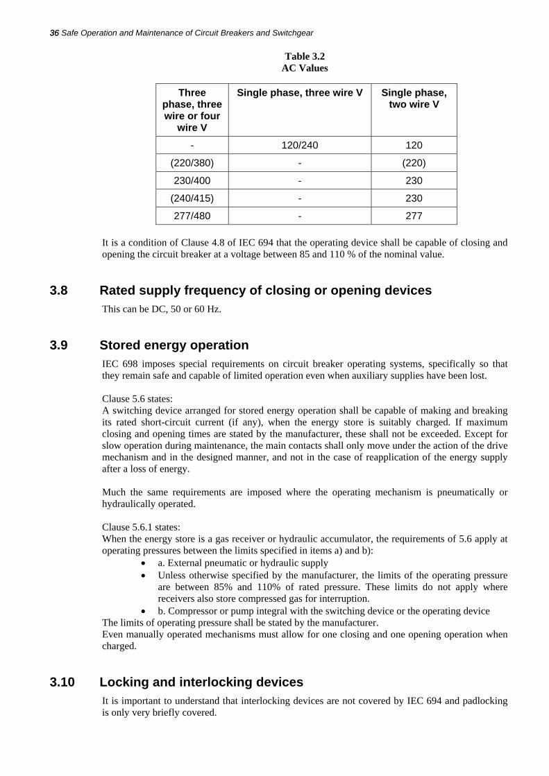
Table 3.2 AC Values
It is a condition of Clause 4.8 of IEC 694 that the operating device shall be capable of closing and opening the circuit breaker at a voltage between 85 and 110 % of the nominal value.
3.8 Rated supply frequency of closing or opening devices This can be DC, 50 or 60 Hz.
3.9 Stored energy operation IEC 698 imposes special requirements on circuit breaker operating systems, specifically so that they remain safe and capable of limited operation even when auxiliary supplies have been lost.
Clause 5.6 states: A switching device arranged for stored energy operation shall be capable of making and breaking its rated short-circuit current (if any), when the energy store is suitably charged. If maximum closing and opening times are stated by the manufacturer, these shall not be exceeded. Except for slow operation during maintenance, the main contacts shall only move under the action of the drive mechanism and in the designed manner, and not in the case of reapplication of the energy supply after a loss of energy. Much the same requirements are imposed where the operating mechanism is pneumatically or hydraulically operated.
Clause 5.6.1 states: When the energy store is a gas receiver or hydraulic accumulator, the requirements of 5.6 apply at operating pressures between the limits specified in items a) and b):
• a. External pneumatic or hydraulic supply • Unless otherwise specified by the manufacturer, the limits of the operating pressure
are between 85% and 110% of rated pressure. These limits do not apply where receivers also store compressed gas for interruption.
• b. Compressor or pump integral with the switching device or the operating device The limits of operating pressure shall be stated by the manufacturer. Even manually operated mechanisms must allow for one closing and one opening operation when charged.
3.10 Locking and interlocking devices It is important to understand that interlocking devices are not covered by IEC 694 and padlocking is only very briefly covered.
Three phase, three wire or four
wire V
Single phase, three wire V Single phase, two wire V
- 120/240 120
(220/380) - (220)
230/400 - 230
(240/415) - 230
277/480 - 277

Switchgear Rating and Specification 37
Clause 5.11 states: Interlocking devices between different components of equipment may be required for reasons of safety and convenience of operation (for example between a switching device and the associated earthing switch). These interlocking devices shall be provided subject to agreement between manufacturer and user. Switching devices, the incorrect operation of which can cause damage or which are used for assuring isolating distances, shall be provided with locking facilities as specified to the manufacturer (for example, provision of padlocks). Thus in the drawing up of a specification for switchgear, attention must be paid to specifying the padlocks and interlocks that will be required, which must fit the Safety Rules and safety policies of the user. The most important safety requirements that need to be considered are:
• The means by which the circuit breaker is to be prevented from closing to ON when the feeder is being worked on.
• The means by which feeder earth will be ensured when a Permit to Work or Sanction for Test is in force.
• The means by which a safe access to the circuit will be obtained for testing purposes, including the provision of a suitable point of isolation.
3.11 Enclosure degrees of protection IEC 694 allows the user to specify the degree of enclosure protection, which follows the same coding as IEC 529 'Degrees of protection afforded by enclosures' (the IP Code). Table 6 of IEC 694 – reproduced below – specifies the choices available to the user, clearly the greater the degree of environmental protection, the greater the cost of the equipment and therefore a balance needs to be achieved.

38 Safe Operation and Maintenance of Circuit Breakers and Switchgear 38
Table 3.3 Table 6 of the IEC 694
Degree of protection
Protection against ingress of solid foreign bodies
Protection against access to hazardous parts
IP1XB Objects of 50 mm diameter and greater
Access with a finger (test-finger 12 mm diameter, 50 mm long)
IP2X Objects of 12.5 mm diameter and greater
Access with a finger (test-finger 12 mm diameter, 80 mm long)
IP2XC Objects of 12.5 mm diameter and greater
Access with a tool (test-rod 2.5 mm diameter, 100 mm long)
IP2XD Objects of 12.5 mm diameter and greater
Access with a wire (test-wire 1.0 mm diameter, 100 mm long)
IP3X Objects of 2.5 mm diameter and greater
Access with a tool (test-rod 2.5 mm diameter, 100 mm long)
IP3XD Objects of 2.5 mm diameter and greater
Access with a wire (test-wire 1.0 mm diameter, 100mm long)
IP4X Objects of 1.0 mm diameter and greater
Access with a wire (test-wire 1.0 mm diameter, 100 mm long)
1P5X Dust - the ingress of dust is not totally prevented, but does not penetrate in a quantity or at a location such that it can interfere with satisfactory operation of apparatus or to impair safety.
Access with a wire (test-wire 1.0 mm diameter, 100 mm long)
NOTE If only the protection against access to hazardous parts is concerned, the additional letter is used and the first numeral is replaced by an X.
3.12 Gas leakage rates In the case of switchgear where the insulation and/or arc extinction is obtained by a gas (normally SF6), IEC 694 specifies the maximum rate at which gas may be lost:
• The rate of gas loss from any single closed compartment is defined as Frel and has a standardised value of either 1% or 3% a year.
• The rate of gas loss from any single sealed compartment is defined as the expected operating life, with standard values of 20 or 40 years.
IEC 298 AC metal enclosed switchgear and control gear for rated voltages above 1 kV and up to and including 52 kV - this specification covers mainly requirements for metallic switchgear enclosures Again, time does not permit a complete review of this standard, but some of the more important clauses are discussed below.
• Vents - Clauses 5.102.6 and 5.104 require that vents, vent openings including pressure relief vents shall be positioned so that escaping gas does not endanger the operator in the course of his normal duties (standing in the operating position). This may be achieved by allowing the arc to burn through the enclosure at designated points.

Switchgear Rating and Specification 39
• Automatic shutters - Clause 5.103 requires that where switchgear is fitted with movable shutters through which contacts or removable parts engage, these shutters shall be automatic in operation. Further, these automatic shutters must be either lockable or be capable of fitting with screens. This requirement generally applies to test contacts and spouts, both feeder and busbar. When, for maintenance purposes, automatic shutters are made inoperative, it shall not be possible for the circuit breaker to be restored to SERVICE until the automatic device has been made operative. This restoration may be achieved when the circuit breaker is returned to SERVICE, that is, restoration may itself be automatic.
• Interlocks - unlike IEC 694, IEC 298 does specify a few important standard interlocks. These are:
a. On metal-enclosed switchgear and controlgear with removable parts, interlocks shall prevent
• The withdrawal or engagement of a circuit-breaker, switch or contactor shall be impossible unless it is in the OPEN position. • The operation of a circuit-breaker, switch or contactor shall be impossible unless it is in the service, disconnected, removed, test or earthing position. • The CLOSING of the circuit-breaker, switch or contactor in the service position unless any auxiliary circuits associated with the automatic opening of these devices are connected. Conversely, it shall not be possible to disconnect the auxiliary circuits with the circuit-breaker closed in the service position.
b. On metal-enclosed switchgear and controlgear without removable parts and provided with disconnectors
• Interlocks shall be provided to prevent operation of disconnectors under conditions other than those they are intended for (see IEC 129). The operation of a disconnector shall not be possible unless the associated circuit-breaker, switch or contactor is in the open position. NOTE This rule may be disregarded if it is possible to have a busbar transfer in a double busbar system without current interruption. • The operation of the circuit-breaker, switch or contactor shall be impossible unless the associated disconnector is in the CLOSED, OPEN or EARTH position (if provided). The provision of additional or alternative interlocks shall be subject to agreement between manufacturer and user. The manufacturer shall give all necessary information on the character and function of interlocks. It is recommended that earthing switches having a short-circuit making capacity less than the rated peak withstand current of the circuit should be interlocked with the associated disconnectors. Apparatus installed in main circuits, the incorrect operation of which can cause damage or which are used for assuring isolating distances during maintenance work, shall be provided with locking facilities (for example provision for padlocks). If earthing of a circuit is provided by a circuit-breaker in series with an earthing switch, the earthing switch shall be interlocked with the circuit-breaker and the circuit-breaker shall be secured against unintentional opening.
• Internal fault : Appendix AA of IEC 298 covers locations, causes and examples of measures decreasing the risk of internal faults on switchgear, or at least reducing the risk of them. It is therefore very relevant to this seminar and Table AA1 from IEC 298 is reproduced below.

40 Safe Operation and Maintenance of Circuit Breakers and Switchgear 40
Table 3.4 Table AA1 from IEC :Locations, causes and examples of measures decreasing the probability
of internal faults or reducing the risk
Locations where internal faults are more likely
to occur (1)
Possible causes of internal faults
(2)
Examples of measures (3)
Inadequate design Selection of adequate dimensions.
Faulty installation Avoidance of crossed cable connections. Checking of workmanship on site.
Cable boxes
Failure of solid or liquid insulation (defective or missing)
Checking of workmanship and/or dielectric test on site. Regular checking of liquid levels.
Disconnectors Switches Earthing Switches
Mal-operation Interlocks. Delayed reopening. Independent manual operation. Making capacity for switches and earthing switches. Instructions to personnel.
Corrosion Use or corrosion inhibiting coating and/or greases. Encapsulation, where possible.
Bolted connections and contacts Faulty assembly Checking of workmanship by suitable means.
Instrument trans-formers
Ferro-resonance Avoidance of these electrical influences by suitable design of the circuit.
Circuit-breakers Insufficient maintenance Regular programmed maintenance, Instructions to personnel.
Error by personnel Limitation of access by compartmentation. Insulationembedded live parts. Instructions to personnel.
Ageing under electric stresses
Partial discharge routine tests.
Pollution, moisture, ingress of dust, vermin, etc.
Measures to ensure that the specified service conditions are achieved. Use of gas-filled compartments.
All locations
Over-voltages Lightning protection. Adequate insulation co-ordina-tion. Dielectric tests on site.
3.13 Testing for Internal Fault Appendix AA1 of IEC 298 specifies a method of testing switchgear enclosures against the effects of internal faults, which has been widely adopted by switchgear manufacturers. It involves setting up deliberate faults within the switchgear enclosures and then testing for the effect by use of what are called 'indicators', that is, large metal screens covered with black Cotton textile material. Because of the importance of this test procedure for operator safety, it is reproduced below in full.
Switchgear Rating and Specification 41
METHOD FOR TESTING THE METAL-ENCLOSED SWITCHGEAR AND CONTROLGEAR UNDER CONDITIONS OF ARCING DUE TO AN INTERNAL FAULT
AA.l Introduction Internal faults inside metal-enclosed switchgear and controlgear can occur in a number of locations and can cause various physical phenomena. For example, the arc energy resulting from an arc developed in air at atmospheric pressure or in another insulating gas within the enclosure will cause an internal overpressure and local overheating which will result in mechanical and thermal stressing of the equipment. Moreover, the materials involved may produce hot decomposition products, either gaseous or vaporous, which may be discharged to the outside of the enclosure. This standard makes allowance for internal overpressure acting on covers, doors, inspection windows, etc. and also takes into consideration the thermal effects of the arc or its roots on the enclosure and of ejected hot gases and glowing particles but not damage to partitions and shutters. Consequently, it does not cover all effects, which may constitute a risk, such as toxic gases. Moreover, the test procedure only simulates situations when doors and covers are closed and correctly secured.
AA.2 Types of accessibility A distinction is made between the two types of accessibility corresponding to the different test conditions given in Sub-clauses AA.5.3.2 and AA.5.3.3, The enclosure may have different types of accessibility on its various sides.
• Type A: Metal-enclosed switchgear and controlgear with accessibility restricted to authorized personnel only.
• Type B: Metal-enclosed switchgear and controlgear with unrestricted accessibility, including that of the general public.
AA.3 Test arrangements The choice of the functional units. Their number, their equipment and their position in the room, as well as the place of initiation of the arc are to be decided between manufacturer and user. In each case, the following points should be observed:
• functional units of representative sizes should be tested. • the mounting conditions should be as close as possible to those of normal service. • the room should be represented at least by the floor, the ceiling, two walls
perpendicular to each other and simulated cable access ways. NOTE If the switchgear is installed in combination with a special exhaust channel, leading the gas out of the room, no room mock-up is necessary. • the functional units should be fully equipped. Mock-ups of internal components are
permitted, provided they have the same volume and external material as the original items. Subclause 5.101.4 should be taken into account.
• the test unit shall be earthed at the point provided. • in the case of gas-filled compartments the test should be made with the original gas at
the rated filling pressure. NOTE - As an alternative and with the agreement of the manufacturer, the test may be carried out with air, but it has to be taken into account that the pressure rise will be different. • the arc shall be initiated in a way that is representative of faults which could occur
under service conditions.
AA.4 Current and voltage applied • AA.4.1 General: The tests on metal-enclosed switchgear and controlgear should be
carried out three-phase. The short-circuit current applied during the test corresponds to the rated short-time withstand current. It may be lower, if specially requited by the manufacturer.
• AA.4.2 Voltage: The applied voltage of the test circuit should be equal to the rated voltage of the metal-enclosed switchgear and controlgear. A lower voltage may be chosen if the following conditions are met:

42 Safe Operation and Maintenance of Circuit Breakers and Switchgear 42
• the current remains practically sinusoidal; • the arc is not extinguished prematurely.
• AA.4.3 Current: • AA.4.3.l AC. component: The short-circuit current for which the metal-
enclosed switchgear and controlgear is specified with respect to arcing should be set within a + 5% - 0% tolerance. This tolerance applies to the prospective current only if the applied voltage is equal to the rated voltage. The current should remain constant.
NOTE - If the test plant does not permit this, the test should be extended until the integral of the ac. component of the current equals the value specified within a tolerance of + 10% - 0%. In this case, the current should be equal to the specified value at least during the first three full cycles and should not be less than 50% of the specified value at the end of the test. • AA.4.3.2 D.C. component: The instant of closing should be chosen so that the
prospective value of the peak current (with a tolerance of + 5% - 0%) flowing in one of the outer phases is 2.5 times the r.ms. value of the ac. component defined in Sub-clause AA.4.3. 1, and so that a major loop also occurs in the other outer phase. If the voltage is lower than the rated voltage, the peak value of the short-circuit current for the metal-enclosed switchgear and controlgear under test should not drop below 90% of the prospective peak value.
• AA.4.4 Frequency: At a rated frequency of 50 Hz or 60 Hz, the frequency at the beginning of the test should be between 48 Hz and 62 Hz. At other frequencies it should not deviate from the rated value by more than ± 10%.
• AA.4.5 Duration of the test: The arc duration is chosen in relation to the probable duration of the arc determined by the protection facilities and should not normally exceed 1 s.
For testing metal-enclosed switchgear and controlgear provided with pressure relief devices, merely for proving its resistance to pressure, an arc duration of 0.1 s is generally sufficient. This does not apply for gas-filled compartments. NOTE It is in general not possible to calculate the permissible arc duration for a current which differs from that used in the test, The maximum pressure during the test will generally not decrease with a shorter arcing time and there is no universal rule according to which the permissible arc duration may be increased with a lower test current.
AA.5 Test procedure
• AA.5.1 Supply circuit: The neutral is only earthed in the case of metal-enclosed switchgear and controlgear to be operated in a solidly earthed system.
• Care shall be taken in order that the connections do not alter the test conditions. • Generally, inside the enclosure, the arc may be fed from two directions: the direction
to be chosen is the one likely to result in the highest stress. • AA.5.2 Arc initiation: The arc should preferably be initiated between the phases by
means of a metal wire of about 0.5 mm diameter or, in the case of segregated phase conductors, between one phase and earth. If the application of such a wire is not practicable in case of arc initiation in a component. it is permissible as an alternative to initiate the fault by other methods. In this case, the method chosen shall be agreed between the manufacturer and the user.
• In functional units where the live pacts are covered by solid insulating material, the arc should be initiated between two adjacent phases or, in the case of segregated phase conductors, between one phase and earth at the following locations: • at gaps in the insulation of insulation-embedded parts; • by perforation at insulated joints made on site when prefabricated insulation
parts are not used. Except for case ii) solid insulation shall not be perforated. The in-feed from the supply circuit shall be three-phase to allow the fault to become three-phase.

Switchgear Rating and Specification 43
The point of initiation shall be chosen so that the effects of the resultant arc produce the highest stresses in the functional unit. In case of doubt it may be necessary to make more than one test on each functional unit. • AA.5.3 Indicator (for observing the thermal effects of gases):
• AA.5.3.1 General: Indicators are pieces of black cotton cloth so arranged that their cut edges do not point toward the test unit. Care shall be taken to see that they cannot ignite each other. This is achieved by fitting them, for example, in a mounting frame of steel sheet (see figure AA.1). The indicator dimensions should be about 150 mm x 150 mm.
• AA.5.3.2 Accessibility Type A: Indicators should be fitted vertically at the operator’s side of the enclosed switchgear and controlgear and, if applicable, at sides which are readily accessible to personnel. They should be placed, up to a height of 2 m and at a distance of 30 cm + 5% from the enclosed switchgear and controlgear, facing all points where gas is likely to be emitted (e.g. joints, inspection windows, doors). Care should be taken when positioning the indicators to take into account the possibility of hot gas escaping in slant directions. Indicators should also be arranged horizontally at a height of 2 m above the floor and between 30 cm and 80 cm from the enclosed switchgear and controlgear, (see Figure AA.2). Black cretonne (cotton fabric approximately 150 g/m2) should be used for the indicators.
• AA.5.3.3 Accessibility Type B: Indicators should be fitted vertically on all accessible sides of the enclosed switchgear and controlgear. They should be placed, up to a height of 2 m and at a distance of 10 cm ± 5% from the enclosed switchgear and controlgear, facing all points where gas is likely to be emitted (e.g. joints, inspection windows, doors). Care should be taken when positioning the indicators should also be arranged horizontally at a height of 2 m above the floor and between 10 cm and 80 cm from the enclosed switchgear and controlgear. If the test unit is lower than 2 m indicators should be placed horizontally on the top covers, facing all points where gas is likely to be emitted and close to the vertical indicators, which in this case, are only required up to the actual height of the equipment, (see Figure AA.2). Black cotton-interlining lawn (approximately 40 g/m2) should be used for the indicators.
AA.6 Assessment of the test The following criteria should be used to record the results of the internal fault tests. It is to be observed: Criterion No. 1 Whether correctly secured doors, covers, etc., do not open. Criterion No. 2 Whether parts which may cause a hazard fly off. This includes large parts or those with sharp edges, for example inspection windows, pressure relief flaps, cover plates, etc. Criterion No. 3 Whether arcing does not cause holes to develop in the freely accessible external parts of the enclosure as a result of burning or other effects. Criterion No. 4 Whether the indicators arranged vertically (Sub-clause AA.5.3) do not ignite. Indicators ignited as a result of paint or stickers burning are excluded from this assessment. Criterion No. 5 Whether the indicators arranged horizontally (Sub-clause AA.5.3) do not ignite. Should they start to burn during the test, the assessment criterion may be regarded as having been met, if proof is

44 Safe Operation and Maintenance of Circuit Breakers and Switchgear 44
established of the fact that the ignition was caused by glowing particles rather than hot gases. Pictures taken by high-speed cameras should be produced in evidence. Criterion No. 6 Whether all the earthing connections are still effective. AA.7 Test report The following information should be given in the test report:
• Rating and description of the test unit with a drawing showing the main dimensions, details relevant to the mechanical strength, the arrangement of the pressure relief flaps and the method of fixing the metal-enclosed switchgear and controlgear to the floor and to the walls.
• Arrangement of the test connections. • Point and method of initiation of the internal fault. • Arrangement and material of indicators with respect to the type of accessibility. For
the prospective or test current: • RMS value of the AC component during the first three half-cycles • Highest peak value • Average value of the AC component over the actual duration of the test • Test duration • Assessment of the test results, including a record of the observations in accordance
with AA6.
3.14 Switchgear ancillaries, measurement CTs and VTs The most important safety aspect of CTs is that they should never be open circuited ON LOAD! Current transformers are specified by IEC 185 'Specification for current transformers' (BS 7626). Figure 3.4 shows the magnetising curve for a 50/5 CT, and displays the defining characteristics of CTs.
Figure 3.4 CT magnetising characteristic
Firstly, the CT is linear over only a limited range, beyond which it becomes non-linear due to magnetic saturation of the Iron core. Secondly it is also non-linear at very low currents, which has implications for metering CTs. In practice, the non-linearity at high currents is not important because the relays are not appreciably affected by further increases in operating current once they have reached a certain limit. It is however important to match the CT ratio to the expected short

Switchgear Rating and Specification 45
circuit currents and to the 'burden' of the relays; in addition, the accuracy class should be matched to the CT function.
The recommended ratios are: 10, 12.5, 15, 20, 25, 30, 40, 50, 60, 75 Amperes or their decimal multiples. The preferred ratios are shown bold. The available accuracy classes are: 0.1, 0.2, 0.5, 1, 3, 5 In general high accuracy classes 0.2 and 0.5 are appropriate only to metering purposes. With the advent of microprocessor relays with very low power requirements ('burden') it has become possible to replace Iron core CTs with air core CTs which are extremely linear; these are called 'Rogowski' coils.
Voltage transformers are specified by IEC 186 (BS 7625). There are no important operational issues with VTs, except that there is a division of opinion as to whether VT fuses should be fitted. Because the smallest size of HV fuse that can be made is just over 3 Amperes and these are sensitive to mechanical damage, there is an argument for leaving VTs unprotected (or protected only by the circuit breaker).

46 Safe Operation and Maintenance of Circuit Breakers and Switchgear 46

Safe Operation and Maintenance of Circuit Breakers and Switchgear
YOU MAY ALSO BE INTERESTED IN THE FOLLOWING TITLE:
This book is available for purchase in
printed form or as an ebook
For more details about this title
please visit the link below:
www.idc-online.com/content/circuit-breakers-and-switchgear-23?id=18
If you would like a quote or any further information please do not hesitate to contact us: