overview of the bison multidimensional fuel performance code · pdf file ·...
TRANSCRIPT
ww
w.in
l.g
ov
Overview of the BISON Multidimensional Fuel Performance Code
Rich Williamson
BISON Team
Jason Hales, Steve Novascone, Ben Spencer,
Danielle Perez, Giovanni Pastore
IAEA Technical Meeting: Modeling of Water-Cooled Fuel
Including Design-Basis and Severe Accidents
October 28 – November 1, Chengdu, China

Outline
• Background
• Code Verification and Validation
• Applications in 3D
– Missing Pellet Surface
– Halden IFA-431 Rod 4 (eccentric vs concentric pellets)
• Priorities for the Future
• Summary

MOOSE-BISON-MARMOT
Multiphysics Object-Oriented Simulation Environment
Atomistic/Mesoscale Material
Model Development
• Predicts microstructure
evolution in fuel
• Used with atomistic methods
to develop multiscale
materials models
• Simulation framework allowing rapid
development of FEM-based applications
Advanced 3D Fuel Performance
Code
• Models LWR, TRISO and metal
fuels in 1D, 2D and 3D
• Steady and transient reactor
operations
• The MOOSE-BISON-MARMOT codes provide an advanced, multiscale
fuel performance capability


Fuel Performance Code
Solution method: Implicit finite element solution of the coupled thermomechanics and species diffusion equations using the MOOSE framework
Multiphysics constitutive models: large deformation mechanics (plasticity and creep), cracking, thermal expansion, densification, radiation effects (swelling, thermal conductivity, etc.).
Massively
parallel, has
been run on
1 - 12,000
cpus.
Substantial experimental
validation is underway
R. L. Williamson, J. D. Hales, S. R. Novascone, M. R. Tonks, D. R. Gaston, C. J. Permann, D.
Andrs and R. C. Martineau, “Multidimensional Multiphysics Simulation of Nuclear Fuel
Behavior,” Journal of Nuclear Materials, 423, 149 (2012)
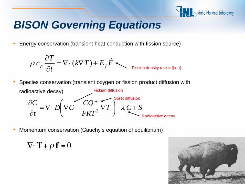
• Energy conservation (transient heat conduction with fission source)
• Species conservation (transient oxygen or fission product diffusion with
radioactive decay)
• Momentum conservation (Cauchy’s equation of equilibrium)
BISON Governing Equations
FETkt
Tc fp
)(
SCTFRT
CQCD
t
C
2
*
Fission density rate = f(x, t)
Fickian diffusion
Soret diffusion
Radioactive decay
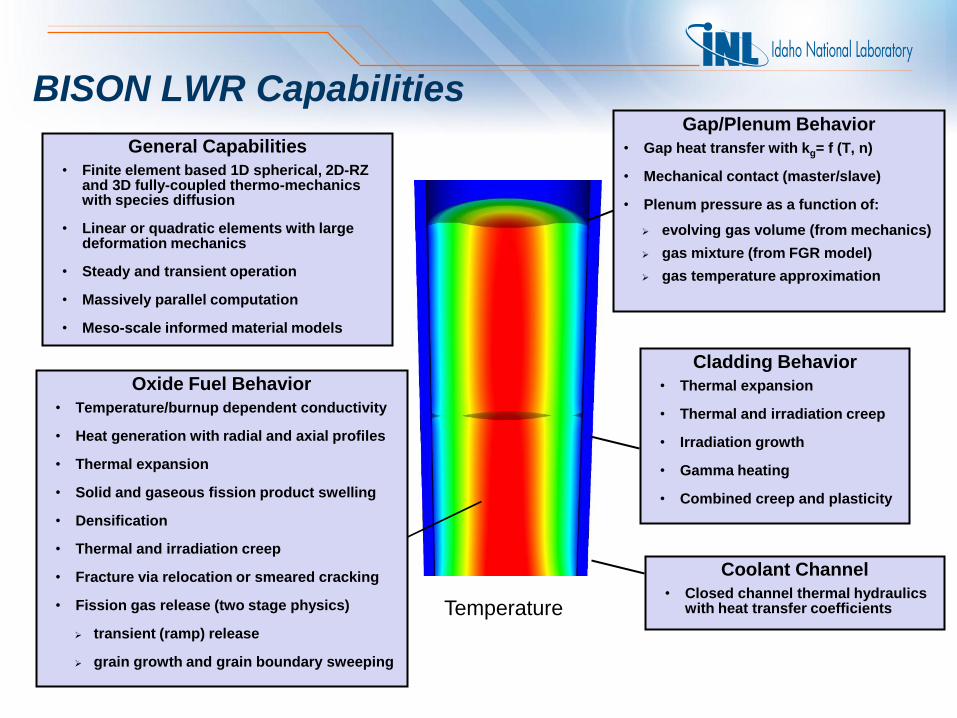
BISON LWR Capabilities
Oxide Fuel Behavior
• Temperature/burnup dependent conductivity
• Heat generation with radial and axial profiles
• Thermal expansion
• Solid and gaseous fission product swelling
• Densification
• Thermal and irradiation creep
• Fracture via relocation or smeared cracking
• Fission gas release (two stage physics)
transient (ramp) release
grain growth and grain boundary sweeping
Cladding Behavior
• Thermal expansion
• Thermal and irradiation creep
• Irradiation growth
• Gamma heating
• Combined creep and plasticity
Gap/Plenum Behavior
• Gap heat transfer with kg= f (T, n)
• Mechanical contact (master/slave)
• Plenum pressure as a function of:
evolving gas volume (from mechanics)
gas mixture (from FGR model)
gas temperature approximation
General Capabilities
• Finite element based 1D spherical, 2D-RZ and 3D fully-coupled thermo-mechanics with species diffusion
• Linear or quadratic elements with large deformation mechanics
• Steady and transient operation
• Massively parallel computation
• Meso-scale informed material models
Temperature
Coolant Channel
• Closed channel thermal hydraulics with heat transfer coefficients

What makes BISON different?
Parallel Computing
CPU 0 CPU 2 CPU 1
Some tasks are embarrassingly
parallel meaning that they do not
require any communication.
For example,
taking the square root of a list of
numbers.
However, most parallel computing
requires communication.
For example, summing a list of
numbers.
Results – Missing Pellet Surface
displacements magnified 25x
• MPS defect results in higher pellet temperatures and much higher clad stress; need for 3D analysis is clear
Simulation of Aspherical TRISO Particle
• Aspherical particles are fairly common
• Single facet aspherical particle problem has been
solved in BISON assuming 2D axisymmetry
200 mm
Time (Ms)
Ta
ng
en
tia
l S
tre
ss
(M
Pa
)
0 20 40 60 80-600
-400
-200
0
200
400
600Aspherical
Spherical
• During accident testing, asphericity raises peak
tensile stress in SiC containment layer by almost 4x
• Typical run times of a few minutes on 8 processors
Time
Te
mp
era
ture
(K
)
500
2000
1500
1000
Irradiation
2.5 yrs
12% FIMA
Step 1
Storage
100 days
Step 2
Furnace
Heating
200 hrs
Step 3
2073 K
300 K
Time (sec)
Th
erm
al
Co
nd
uct
ivit
y (
W/m
/K)
0 20000 40000 60000-0.5
0
0.5
1
1.5
2
2.5
3
AEH_x
AEH_y
Direct_x
Direct_y
Thermal Conductivity from MARMOT
• The direct method is sensitive to bubbles
on the boundary
• Boundary bubbles result in low local
temperature
• This results in a low average temperature
and thus a low thermal conductivity
• The AEH technique is not sensitive to
local effects
Temperature from the direct approach with flux applied in the x (left) and y (right)
directions. Note areas of low temperature in the x-direction plot.
3D/Arbitrary Geometry Parallel Computing
Coupling Fuel Types

Outline
• Background
• Code Verification and Validation
• Applications in 3D
– Missing Pellet Surface
– Halden IFA-431 Rod 4 (eccentric vs concentric pellets)
• Priorities for the Future
• Summary
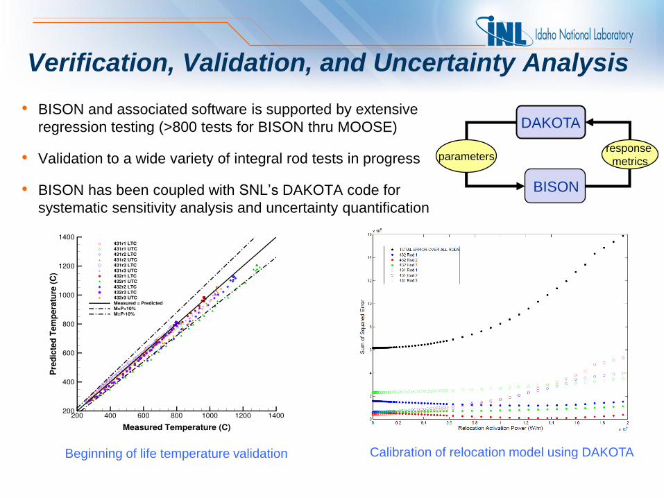
Verification, Validation, and Uncertainty Analysis
Beginning of life temperature validation Calibration of relocation model using DAKOTA
• BISON and associated software is supported by extensive
regression testing (>800 tests for BISON thru MOOSE)
• Validation to a wide variety of integral rod tests in progress
• BISON has been coupled with SNL’s DAKOTA code for
systematic sensitivity analysis and uncertainty quantification
DAKOTA
BISON
response
metrics parameters

BISON Code Assessment Comparisons to integral fuel rod data (21 rods, ~ 35 measurements)
Experiment Rod FCT - BOL FCT – TL
FCT -
Ramps FGR Clad - Elong
Clad – Dia
(PCMI)
IFA-431 1, 2, 3 X
IFA-432 1, 2, 3 X X
IFA-513* 1, 6 X X
IFA-515.10 A1 X X
IFA-597.3 7 X X
IFA-597.3* 8 X
RISO-3* AN3 X X
RISO-3* AN4 X X
FUMEX-II 27(1) X
FUMEX-II 27(2a) X
FUMEX-II 27(2b) X
FUMEX-II 27(2c) X
RISO-3 GE7 X X
OSIRIS J12 X
REGATE X X
IFA-431 (3D) 4 X
*Early User Assessment problems
D. M. Perez, R. L. Williamson, S. R. Novascone, T. K. Larson, J. D. Hales, B. W. Spencer and G. Pastore, An Evaluation
of the Nuclear Fuel Performance Code BISON, Int. Conf. on Mathematics and Computation Applied to Nuclear Science &
Engineering (M&C 2013) Sun Valley, Idaho, May 5-9, 2013.

Beginning of Life Fuel Centerline Temperature
• Very good
comparisons for
the eleven
measurements
considered to date
• BOL comparisons
validate important
physics such as
power input, fuel
and clad thermal
conductivity, gap
gas conductivity,
fuel and clad
thermal expansion,
gap closure and
fuel relocation
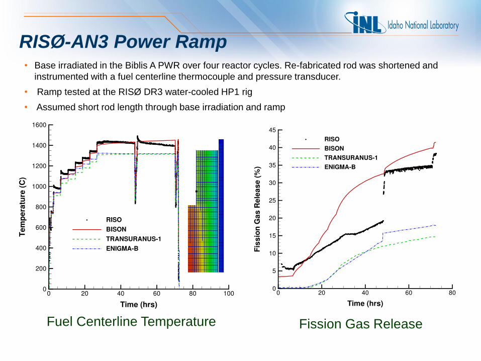
RISØ-AN3 Power Ramp
Fuel Centerline Temperature Fission Gas Release
• Base irradiated in the Biblis A PWR over four reactor cycles. Re-fabricated rod was shortened and
instrumented with a fuel centerline thermocouple and pressure transducer.
• Ramp tested at the RISØ DR3 water-cooled HP1 rig
• Assumed short rod length through base irradiation and ramp
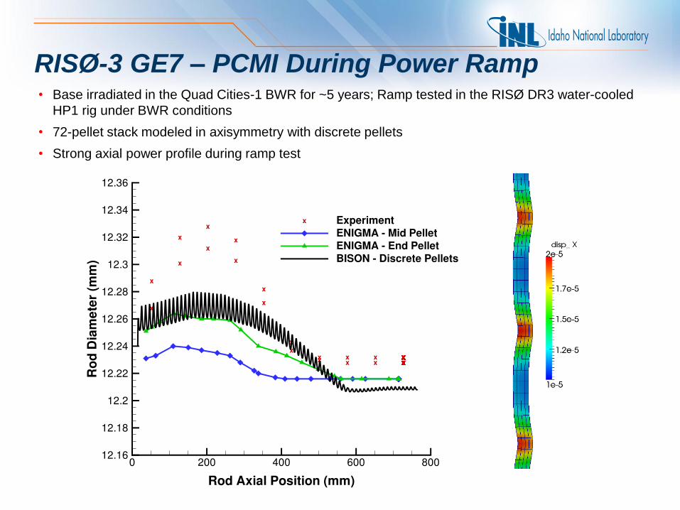
RISØ-3 GE7 – PCMI During Power Ramp • Base irradiated in the Quad Cities-1 BWR for ~5 years; Ramp tested in the RISØ DR3 water-cooled
HP1 rig under BWR conditions
• 72-pellet stack modeled in axisymmetry with discrete pellets
• Strong axial power profile during ramp test

Outline
• Background
• Code Verification and Validation
• Applications in 3D
– Missing Pellet Surface
– Halden IFA-431 Rod 4 (eccentric vs concentric pellets)
• Priorities for the Future
• Summary

Zr-4
clad
He fill gas
Missing pellet
surface
UO2
fuel
PCMI - Missing Pellet Surface Analysis
• High resolution 3D calculation (250,000 elements, 1.1x10⁶ dof) run on 120 processors
• Simulation from fresh fuel state with a typical power history, followed by a late-life power ramp
Cross-section of rod that
failed due to MPS defect
(from Aleshin et al, 2010)
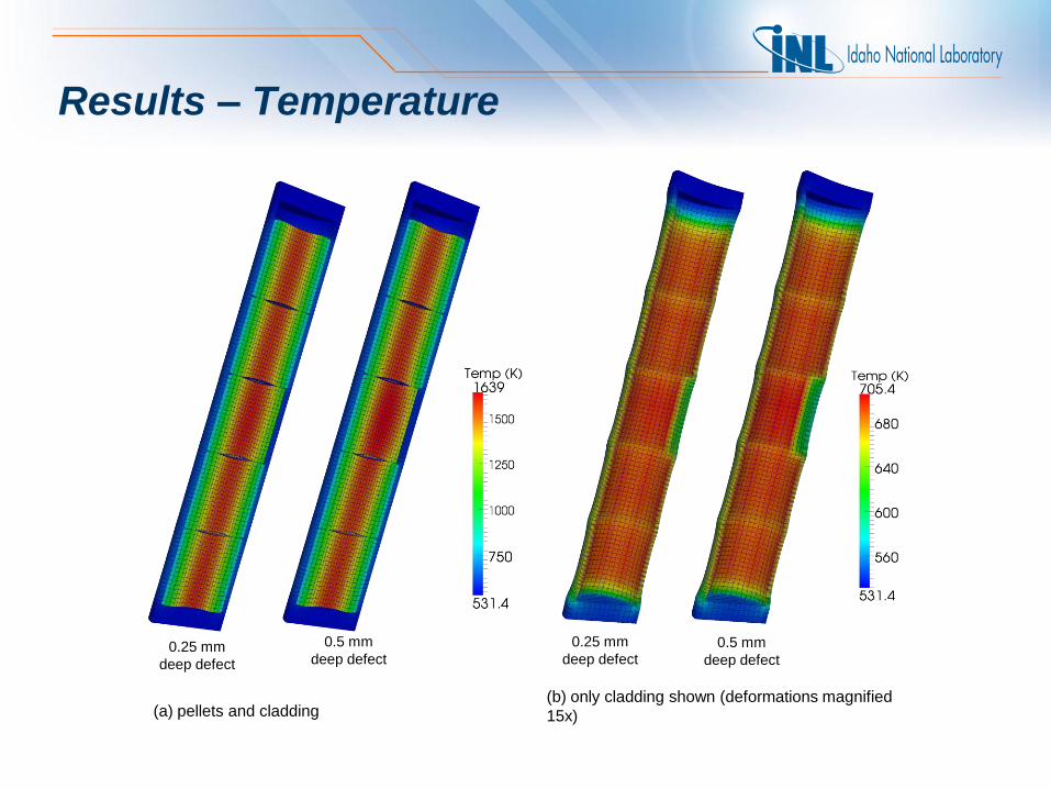
Results – Temperature
(a) pellets and cladding (b) only cladding shown (deformations magnified
15x)
0.25 mm
deep defect
0.5 mm
deep defect
0.25 mm
deep defect 0.5 mm
deep defect

Results – Clad Creep Strain
0.25 mm
deep defect
0.5 mm
deep defect
Zoomed-in view of 0.5 mm deep defect
• Creep during base irradiation plays significant role in relaxing
stresses
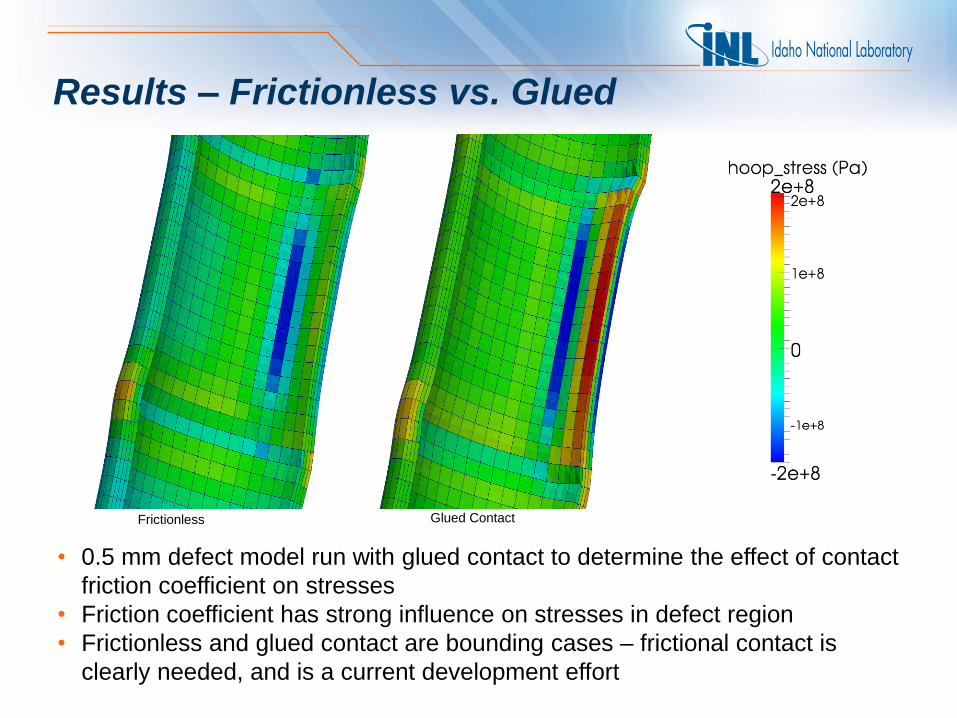
Results – Frictionless vs. Glued
Frictionless Glued Contact
• 0.5 mm defect model run with glued contact to determine the effect of contact
friction coefficient on stresses
• Friction coefficient has strong influence on stresses in defect region
• Frictionless and glued contact are bounding cases – frictional contact is
clearly needed, and is a current development effort

IFA-431 Rod 4 – Concentric vs. Eccentric Pellets
• Several pellets locked in position (radially) by oversize pellets, thermocouples and Mo rods
• Top section held concentrically; Bottom section held eccentrically
• Rod Fill gas – 100% Xe
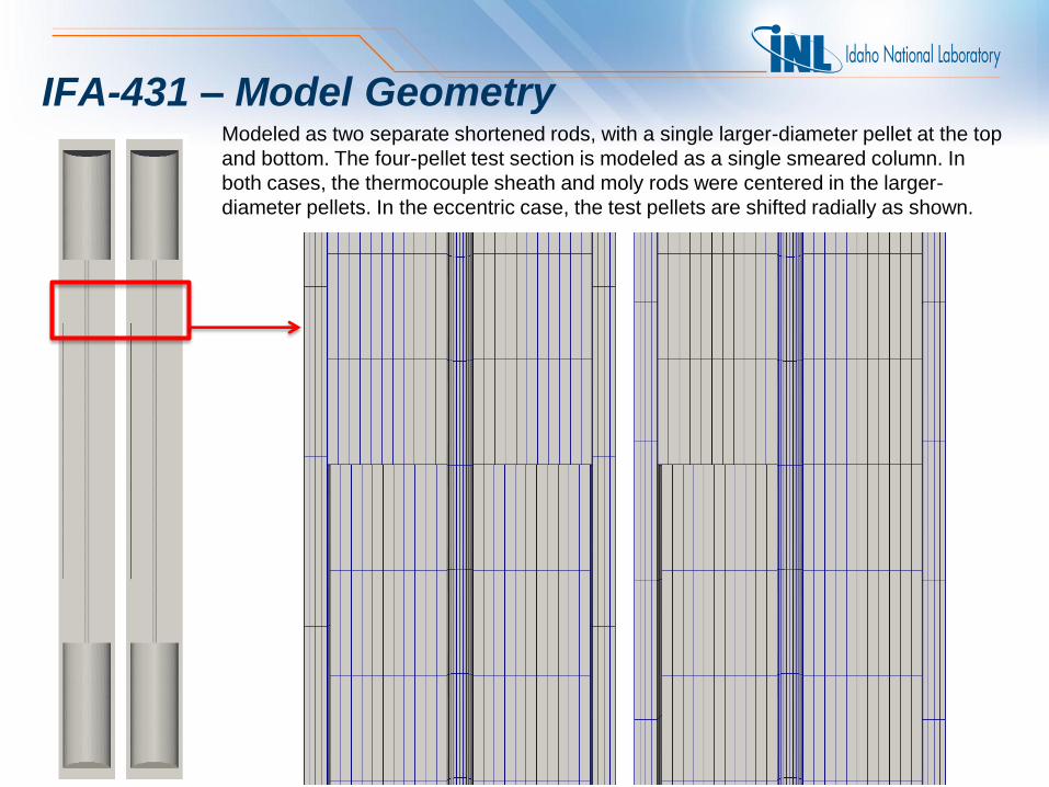
IFA-431 – Model Geometry Modeled as two separate shortened rods, with a single larger-diameter pellet at the top
and bottom. The four-pellet test section is modeled as a single smeared column. In
both cases, the thermocouple sheath and moly rods were centered in the larger-
diameter pellets. In the eccentric case, the test pellets are shifted radially as shown.
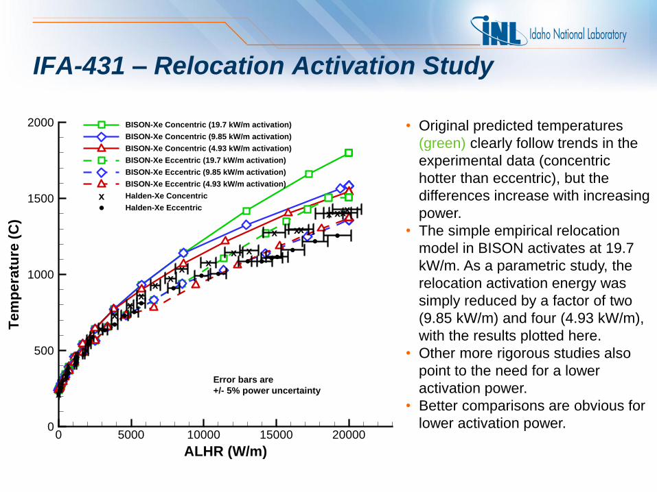
IFA-431 – Relocation Activation Study
• Original predicted temperatures
(green) clearly follow trends in the
experimental data (concentric
hotter than eccentric), but the
differences increase with increasing
power.
• The simple empirical relocation
model in BISON activates at 19.7
kW/m. As a parametric study, the
relocation activation energy was
simply reduced by a factor of two
(9.85 kW/m) and four (4.93 kW/m),
with the results plotted here.
• Other more rigorous studies also
point to the need for a lower
activation power.
• Better comparisons are obvious for
lower activation power.
xxxx
xxx
x
xx
xx
xx
xx x
x xx
x xxx
ALHR (W/m)
Te
mp
era
ture
(C
)
0 5000 10000 15000 200000
500
1000
1500
2000 BISON-Xe Concentric (19.7 kW/m activation)
BISON-Xe Concentric (9.85 kW/m activation)
BISON-Xe Concentric (4.93 kW/m activation)
BISON-Xe Eccentric (19.7 kW/m activation)
BISON-Xe Eccentric (9.85 kW/m activation)
BISON-Xe Eccentric (4.93 kW/m activation)
Halden-Xe Concentric
Halden-Xe Eccentric
x
Error bars are
+/- 5% power uncertainty

IFA-431 – BOL Fuel Centerline Temperature
• Shown is a comparison of
predicted temperatures for
the concentric and eccentric
rods at a LHGR of 20 kW/m.
• The peak temperature for
eccentrically positioned
pellets is clearly lower than
for concentric pellets
• Additionally, in the eccentric
case, the thermocouple is
not sensing the highest
temperature region in the
fuel. Clad inner wall temperature:
547 547
553 596

AP-1000 Preliminary Simulation
Temperature and magnified displacement results for an AP1000 core
Each rod shown is a unique BISON simulation Temperature and magnified displacement results for an AP1000 core
Each rod shown is a unique BISON simulation Temperature and magnified displacement results for an AP1000 core
Each rod shown is a unique BISON simulation Temperature and magnified displacement results for an AP1000 core
Each rod shown is a unique BISON simulation
Temperature and magnified displacement results for an AP1000
core. Each rod shown is a unique BISON simulation.
Loosely
coupled:
• BISON
• RattleSnake
• R7
• Marmot

Outline
• Background
• Code Verification and Validation
• Applications in 3D
– Missing Pellet Surface
– Halden IFA-431 Rod 4 (eccentric vs concentric pellets)
• Priorities for the Future
• Summary
Path Forward – Validation and UQ
• Completed: ~ 20 LWR cases, 13 TRISO cases
• Many, many more are needed; major emphasis for FY-14
- FUMEX-II and -III priority cases
- Halden collaboration
- NNL collaboration on ENIGMA cases
• Participation in FUMAC
• Develop systematic approach to frequently run and compare all
cases and update documentation
• Sensitivity analyses and UQ studies – DAKOTA and RAVEN

Modeling Accident Behavior (RIA and LOCA)
• Much of the required framework is in place:
– Transient operators with adaptive time stepping
– Arbitrary geometry with large deformation mechanics
– Implicit numerics with fully coupled physics
– Fission gas coupled to swelling
• Development areas:
– Multiphysics coupling
Neutronics (RIA)
Thermal-fluids (LOCA)
– Fuel material behavior
Fission gas burst model
Novel fracture models for extensive fuel cracking
Nakamura et al., 2000
Nakamura et al., 2000

Modeling Accident Behavior - continued
– Clad material behavior
Temperature and strain rate
dependent plasticity models
Rapid steam oxidation, with
a moving material interface
Hydrogen diffusion and
embrittlement
High temperature creep
and plasticity
Ballooning (large plasticity)
and burst (failure models
and discrete fracture via
XFEM)
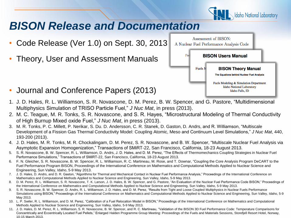
BISON Release and Documentation
• Code Release (Ver 1.0) on Sept. 30, 2013
• Theory, User and Assessment Manuals
• Journal and Conference Papers (2013)
1. J. D. Hales, R. L. Williamson, S. R. Novascone, D. M. Perez, B. W. Spencer, and G. Pastore, “Multidimensional
Multiphysics Simulation of TRISO Particle Fuel,” J Nuc Mat, in press (2013).
2. M. C. Teague, M. R. Tonks, S. R. Novascone, and S. R. Hayes, “Microstructural Modeling of Thermal Conductivity
of High Burnup Mixed oxide Fuel,” J Nuc Mat, in press (2013). 3. M. R. Tonks, P. C. Millett, P. Nerikar, S. Du. D. Andersson, C. R. Stanek, D. Gaston, D. Andrs, and R. Williamson, “Multiscale
Development of a Fission Gas Thermal Conductivity Model: Coupling Atomic, Meso and Continuum Level Simulations,” J Nuc Mat, 440,
193-200 (2013).
4. J. D. Hales, M. R. Tonks, M. R. Chockalingam, D. M. Perez, S. R. Novascone, and B. W. Spencer, “Multiscale Nuclear Fuel Analysis via
Asymptotic Expansion Homogenization,” Transactions of SMiRT-22, San Francisco, California, 18-23 August 2013. 5. S. R. Novascone, B. W. Spencer, R. L. Williamson, D. Andrs, J. D. Hales, and D. M. Perez, “The Effects of Thermomechanics Coupling Strategies in Nuclear Fuel
Performance Simulations,” Transactions of SMiRT-22, San Francisco, California, 18-23 August 2013.
6. F. N. Gleicher, S. R. Novascone, B. W. Spencer, R. L. Williamson, R. C. Martineau, M. Rose, and T. Downar, “Coupling the Core Analysis Program DeCART to the
Fuel Performance Program BISON, Proceedings of the International Conference on Mathematics and Computational Methods Applied to Nuclear Science and
Engineering, Sun Valley, Idaho, 5-9 May 2013. 7. J. D. Hales, D. Andrs, and D. R. Gaston, “Algorithms for Thermal and Mechanical Contact in Nuclear Fuel Performance Analysis,” Proceedings of the International Conference on
Mathematics and Computational Methods Applied to Nuclear Science and Engineering, Sun Valley, Idaho, 5-9 May 2013.
8. D. M. Perez, R. L. Williamson, S. R. Novascone, T. K. Larson, J. D. Hales, B. W. Spencer, and G. Pastore, “An Evaluation of the Nuclear Fuel Performance Code BISON,” Proceedings of
the International Conference on Mathematics and Computational Methods Applied to Nuclear Science and Engineering, Sun Valley, Idaho, 5-9 May 2013.
9. S. R. Novascone, B. W. Spencer, D. Andrs, R. L. Williamson, J. D. Hales, and D. M. Perez, “Results from Tight and Loose Coupled Multiphysics in Nuclear Fuels Performance
Simulations using BISON,” Proceedings of the International Conference on Mathematics and Computational Methods Applied to Nuclear Science and Engineering, Sun Valley, Idaho, 5-9
May 2013.
10. L. P. Swiler, R. L. Williamson, and D. M. Perez, “Calibration of a Fuel Relocation Model in BISON,” Proceedings of the International Conference on Mathematics and Computational
Methods Applied to Nuclear Science and Engineering, Sun Valley, Idaho, 5-9 May 2013.
11. J. D. Hales, D. M. Perez, R. L. Williamson, S. R. Novascone, B. W. Spencer, and R. C. Martineau, “Validation of the BISON 3D Fuel Performance Code: Temperature Comparisons for
Concentrically and Eccentrically Located Fuel Pellets,” Enlarged Halden Programme Group Meeting: Proceedings of the Fuels and Materials Sessions, Storefjell Resort Hotel, Norway,
10-15 March 2013.
Summary
• BISON is being leveraged across multiple US-DOE programs and is
in use at multiple national and international laboratories, many
universities and in industry
• User base is expanding… user support efforts are significant
• Roughly 20 integral rod LWR and 13 TRISO validation cases have
been completed… many more are needed
• BISON used to do first-ever simulation of 3D pellet eccentricity
experiment (invited paper at Halden Reactor Program Meeting)
• Major new capability completed for TRISO-coated particle fuel
• Numerous new applications (metal plate fuel, fast reactor oxide fuel,
accident tolerant fuel designs, ATR experiment design)
demonstrate BISON’s versatility
• First official code release was September 30, 2013
FCRD
30

The National Nuclear Laboratory
31

Individual
Applications
Common fuels
related physics
Common non-fuels
related physics
Animal Hierarchy
MOOSE
ELK
FOX
Peregrine BISON
Common component interface
and solution scheme

RISO-3 AN3 • FUMEX-II Priority Case
• Fuel pin CB8 was base irradiated in the Biblis A PWR over four reactor cycles
• Re-fabricated fuel pin (CB8-2R) was shortened from the CB8 rod and
instrumented with a fuel centerline thermocouple and pressure transducer.
• CB8-2R was ramp tested at the Riso DR3 water-cooled HP1 rig
• Assumed short rod length through base irradiation for simulation
• Modeled as 2D-RZ axisymmetric with smeared pellets; Quadratic elements
Aspect ratio scaled 10x
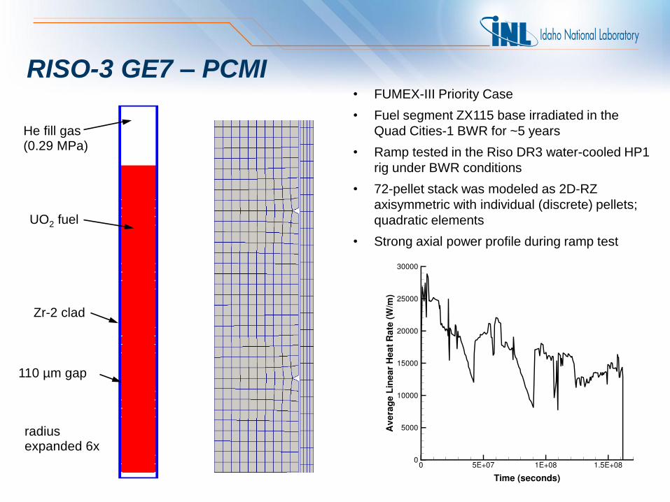
RISO-3 GE7 – PCMI • FUMEX-III Priority Case
• Fuel segment ZX115 base irradiated in the
Quad Cities-1 BWR for ~5 years
• Ramp tested in the Riso DR3 water-cooled HP1
rig under BWR conditions
• 72-pellet stack was modeled as 2D-RZ
axisymmetric with individual (discrete) pellets;
quadratic elements
• Strong axial power profile during ramp test
Zr-2 clad
He fill gas (0.29 MPa)
110 mm gap
UO2 fuel
radius expanded 6x
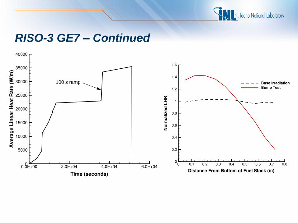
RISO-3 GE7 – Continued
100 s ramp
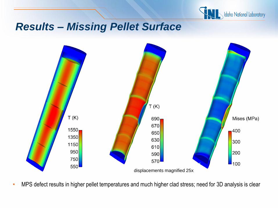
Results – Missing Pellet Surface
displacements magnified 25x
• MPS defect results in higher pellet temperatures and much higher clad stress; need for 3D analysis is clear
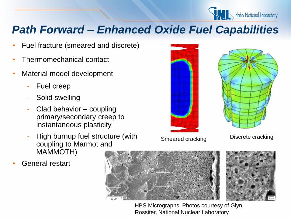
Path Forward – Enhanced Oxide Fuel Capabilities
• Fuel fracture (smeared and discrete)
• Thermomechanical contact
• Material model development
- Fuel creep
- Solid swelling
- Clad behavior – coupling primary/secondary creep to instantaneous plasticity
- High burnup fuel structure (with coupling to Marmot and MAMMOTH)
• General restart
HBS Micrographs, Photos courtesy of Glyn
Rossiter, National Nuclear Laboratory
Smeared cracking Discrete cracking
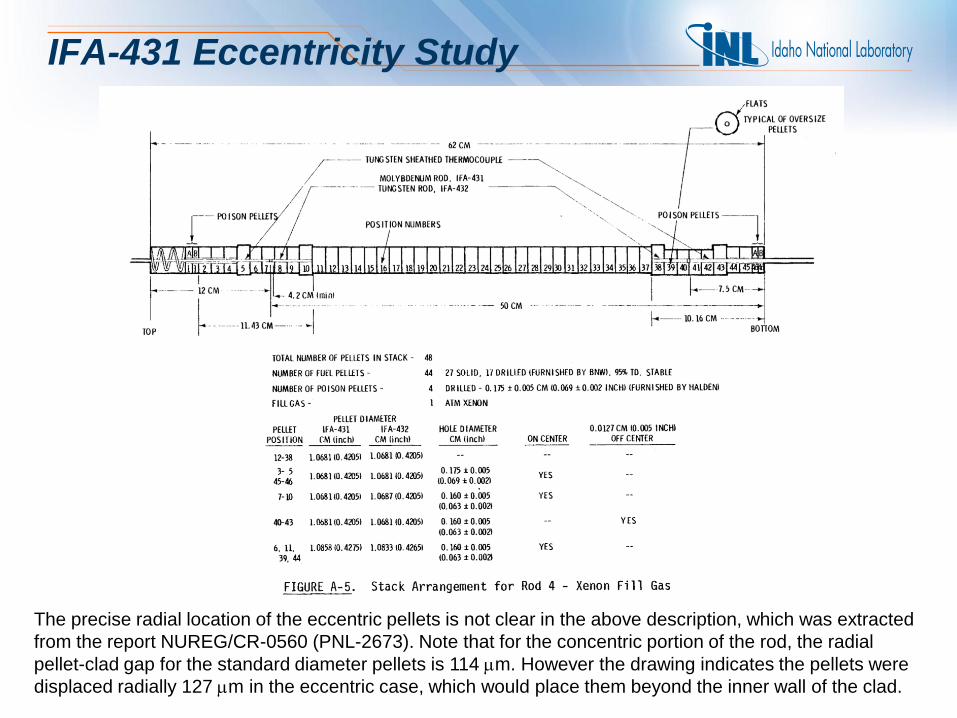
IFA-431 Eccentricity Study
The precise radial location of the eccentric pellets is not clear in the above description, which was extracted
from the report NUREG/CR-0560 (PNL-2673). Note that for the concentric portion of the rod, the radial
pellet-clad gap for the standard diameter pellets is 114 mm. However the drawing indicates the pellets were
displaced radially 127 mm in the eccentric case, which would place them beyond the inner wall of the clad.
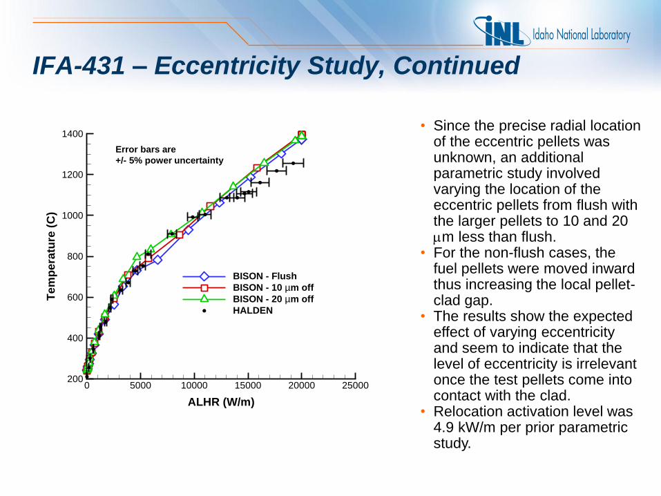
IFA-431 – Eccentricity Study, Continued
• Since the precise radial location of the eccentric pellets was unknown, an additional parametric study involved varying the location of the eccentric pellets from flush with the larger pellets to 10 and 20 mm less than flush.
• For the non-flush cases, the fuel pellets were moved inward thus increasing the local pellet-clad gap.
• The results show the expected effect of varying eccentricity and seem to indicate that the level of eccentricity is irrelevant once the test pellets come into contact with the clad.
• Relocation activation level was 4.9 kW/m per prior parametric study.
ALHR (W/m)
Te
mp
era
ture
(C
)
0 5000 10000 15000 20000 25000200
400
600
800
1000
1200
1400
BISON - Flush
BISON - 10 mm off
BISON - 20 mm off
HALDEN
Error bars are
+/- 5% power uncertainty

User Training
Workshop Materials
• ~ 200 slides
• Overview, Getting Started, Theory, Example Problem, Mesh Generation, Post Processing, Adding a New Material
BISON 2-day Workshops
• INL – January 2012
• MIT – January 2012
• Anatech – Feb 2012
• INL – May 2012 (23 participants)
• NNL (UK) – September 2012
• INL – December 2012 (15 participants)
• INL – June 2013 (11 participants)
• WEC – Aug 2013 (10 participants)
• INL – Dec 2013 (planned)