overview of the phits code and its application to medical...
TRANSCRIPT
1
T. Sato1, K. Niita2, N. Matsuda1, S. Hashimoto1, Y. Iwamoto1, H. Iwase3, H. Nakashima1,
T. Fukahori1, S. Chiba4,1, L. Sihver5
1. Japan Atomic Energy Agency, JAEA, Japan2. Research Organization for Information Science and Technology, RIST, Japan
3. High Energy Accelerator Research Organization, KEK, Japan4. Tokyo Institute of Technology, TITech, Japan5. Chalmers University of Technology, Sweden
Workshop on Computational Medical Physics, Nara, Japan, Sep. 2, 2012
Overview of the PHITS Code and its Application to Medical Physics
2
Table of Contents1. Overview of PHITS
2. Applications to Medical Physics3. Summary
1.1 General Features1.2 Physical Models1.3 Microdosimetric Function
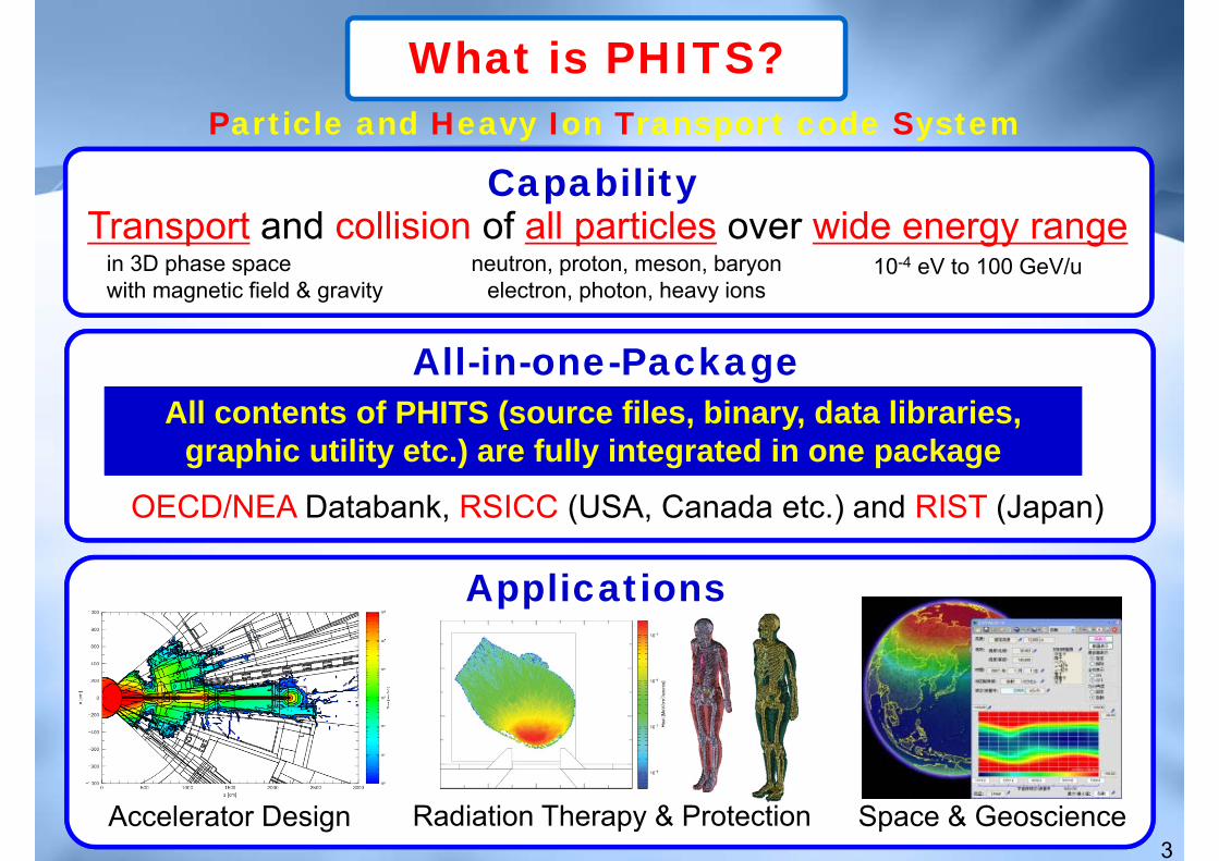
Particle and Heavy Ion Transport code System
CapabilityTransport and collision of all particles over wide energy range
in 3D phase spacewith magnetic field & gravity
neutron, proton, meson, baryon electron, photon, heavy ions
10-4 eV to 100 GeV/u
3
What is PHITS?
All contents of PHITS (source files, binary, data libraries, graphic utility etc.) are fully integrated in one package
All contents of PHITS (source files, binary, data libraries, graphic utility etc.) are fully integrated in one package
All-in-one-Package
OECD/NEA Databank, RSICC (USA, Canada etc.) and RIST (Japan)
Applications
Accelerator Design Radiation Therapy & Protection Space & Geoscience

PHITS Development Team
4
GeneralContract
JAEA
KEK
•Programming• Improvement of nuclear reaction model
RIST
Kyushu Univ.
Chalmers (Sweden)
RIKEN
JAXA
•Managing all the projects
•Tutorial•Distribution
• Incorporating EGS5
• Improvement and verification of nuclear reaction model
•Application to space science and biology
•Tutorial in Europe
•Application to space science
•Application to biology using super computer “Kei”
CEA (France)• Implementation and improvement of INCL model
PHITS is a young code (born in 2001), but the project is getting bigger & bigger PHITS is a young code (born in 2001), but the project is getting bigger & bigger
Future plan
5
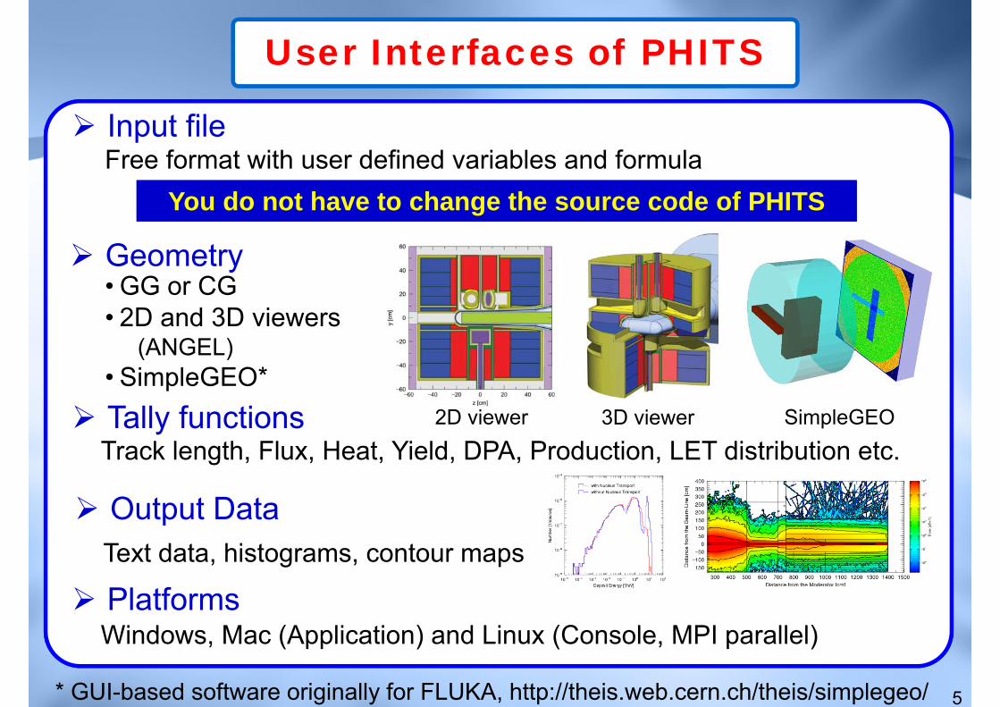
User Interfaces of PHITS
Input fileFree format with user defined variables and formula
You do not have to change the source code of PHITSYou do not have to change the source code of PHITS
Geometry• GG or CG• 2D and 3D viewers
(ANGEL)• SimpleGEO* Tally functionsTrack length, Flux, Heat, Yield, DPA, Production, LET distribution etc.
Output DataText data, histograms, contour maps
* GUI-based software originally for FLUKA, http://theis.web.cern.ch/theis/simplegeo/
2D viewer 3D viewer SimpleGEO
PlatformsWindows, Mac (Application) and Linux (Console, MPI parallel)
6
Table of Contents1. Overview of PHITS
2. Applications to Medical Physics3. Summary
1.1 General Features1.2 Physical Models1.3 Microdosimetric Function

Low-energy NeutronPhoton, Electron
7
Physical Processes included in PHITS
Transport betweencollisions
Collision withnucleus
• Magnetic Field• Gravity• Super mirror (reflection)• Mechanical devices, T0 chopper
External Field and Optical devices
Ionization processfor charge particle
• dE/dx : SPAR, ATIMA codeContinuous-slowing-downApproximation (CSDA)
• Microdosimetric function (unique feature)
Nuclear Data (ENDF, JENDL,…)Event Generator Mode
High-energy Particle
Heavy Ion
JAM codeJAMQMD
JQMD code

8
Map of Models used in PHITS
Event generator mode:Specify secondary charged particles produced fromlow-energy neutron interaction
IonizationSPAR or ATIMA
Neutron Other hadrons(proton, pion etc.) Nucleus Electron
/Positron
Intra-Nuclear Cascade Model(JAM, Bertini)
+Evaporation & Fission Model
(GEM)
Quantum Molecular Dynamics(JQMD)
+Evaporation
(GEM)Nuclear
Data Library(JENDL-4.0)
Muon
Atomic Data
Library
(JENDL /EPDL)
Atomic Data
Library(JENDL)
Photon
200 GeV 100 GeV/n
20 MeV
10-5 eV
1 MeV
1 keV
10 MeV/n
100 GeV100 GeV
1 keV 1 keV
Photo-Nuclear
20 MeV
Low
←
E
nerg
y →
H
igh
Switching energies can be changed in input file of PHITS

9
Table of Contents1. Overview of PHITS
2. Applications to Medical Physics3. Summary
1.1 General Features1.2 Physical Models1.3 Microdosimetric Function

10
Microscopic and Macroscopic Simulation
Target size: Cell or DNA (nm ~ μm orders)Ionization and excitation: event-by-eventLowest energy: a few eVPhysical index for expressing radiation quality:Pattern of ionization
Microscopic Simulation (Track structure simulation)
cannot be directly incorporated into marcoscopic simulationcannot be directly incorporated into marcoscopic simulation
Target size: human body or bigger materials (mm ~ m orders)Ionization and excitation:CSDA or Condensed history simulationLowest energy: ~ 1 keVPhysical index for expressing radiation quality: LET
Radiation quality of HZE particles cannot be uniquely determined from LET,because the energy dispersion due to δ-ray productions is not considered
Macroscopic Simulation (PHITS etc)
characterized by ionization density in microscopic sites such as Lineal energy (y) or Specific energy (z)
Time consumptive!!
11
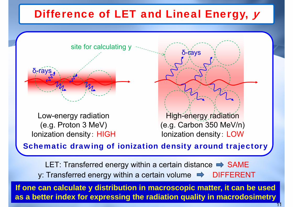
Difference of LET and Lineal Energy, y
Schematic drawing of ionization density around trajectory
If one can calculate y distribution in macroscopic matter, it can be used as a better index for expressing the radiation quality in macrodosimetryIf one can calculate y distribution in macroscopic matter, it can be used as a better index for expressing the radiation quality in macrodosimetry
Low-energy radiation(e.g. Proton 3 MeV)
Ionization density: HIGH
δ-rayssite for calculating y
δ-rays
High-energy radiation(e.g. Carbon 350 MeV/n)Ionization density: LOW
LET: Transferred energy within a certain distance SAMEy: Transferred energy within a certain volume DIFFERENT

12
Implementation of Microdosimetric Function
Calculate probability density of lineal energy, yf(y), around the trajectory of several kinds of HZE particles,
using a microscopic simulation code TRACEL
Incorporating
Propose a mathematical function* that can instantaneously calculate yf(y) around the trajectory of all HZE particles
Improve PHITS to be capable of estimating yf(y) in macroscopic matters
Based on …
GAP
Calculating the lineal energy distribution, yf(y)
{ } ( )i
s
/ 2(d)2 2 6p7i 1 7
1 p(d) 2(d / d ) (d)1 111
( )/ 1( ) ( ) exp21 2e
y w
k ki iB y C E x
k ikk
y yy w j PAzyf y P yjjφ
μ δπ−
= =
⎧ ⎫− −⎛ ⎞− ⎪ ⎪= + + + ⎨ ⎬⎜ ⎟ Γ− Γ ⎪ ⎪⎝ ⎠ ⎩ ⎭∑ ∑
*T. Sato et al. Radiat. Prot. Dosim. 122, 41 (2006)

13
Examples of yf(y) calculated by PHITS
Probability density of y for site diameter 1 μm around the trajectories of high-energy carbon ion and low-energy proton having the same LET
• Data for high-energy carbon ion are shifted to lower y region• Lower RBE of high-energy particle is properly expressed by yf(y)• Data for high-energy carbon ion are shifted to lower y region• Lower RBE of high-energy particle is properly expressed by yf(y)
10−1 100 101 10210−3
10−2
10−1
y (keV/μm)
y f(y
)Proton 3MeVCarbon 350MeV/u
LET = 12 (keV/μm)

14
RBE for HSG cell SF in slab phantom irradiated by several kinds of HZE beams
0 10 201
2
3
4
5
Depth from front surface (g/cm2)
RBE
10
Cal. (This work)C 290MeV/n Mono
C 290MeV/n SOBPC 400MeV/n SOBP
Ne 230MeV/n MonoFe 200MeV/n Mono
Exp. data: Y. Kase et al, 2006
Application of Microdosimetric Function
Relative Biological Effectiveness (RBE) for Cell-Survival Fraction PHITS + Microdosimetric Kinetic (MK) model*
HZE beam
*R. Hawkins (1996)require yf(y) as the input parameter
Important for using PHITS in treatment planning of charged particle therapyImportant for using PHITS in treatment planning of charged particle therapyT. Sato et al. Radiat. Res. 171, 107 (2009)

15
Table of Contents1. Overview of PHITS
2. Applications to Medical Physics3. Summary
1.1 General Features1.2 Physical Models1.3 Microdosimetric Function
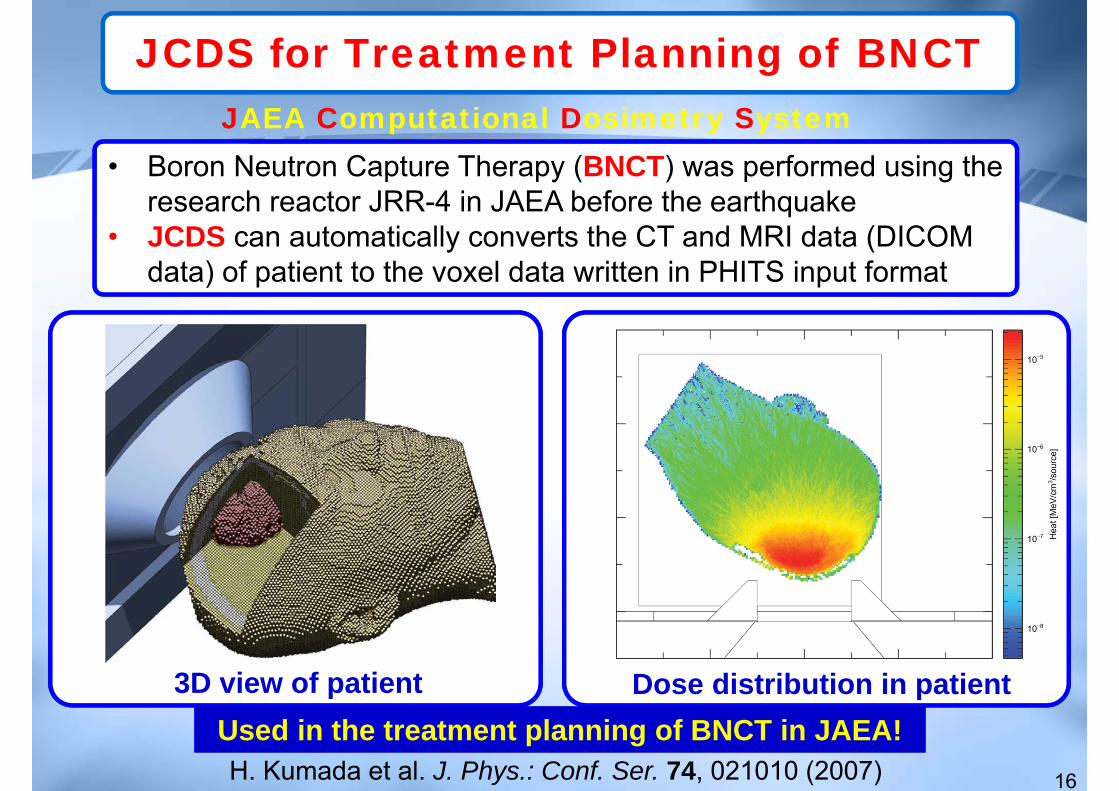
• Boron Neutron Capture Therapy (BNCT) was performed using the research reactor JRR-4 in JAEA before the earthquake
• JCDS can automatically converts the CT and MRI data (DICOM data) of patient to the voxel data written in PHITS input format
16
JCDS for Treatment Planning of BNCT
3D view of patient
JAEA Computational Dosimetry System
H. Kumada et al. J. Phys.: Conf. Ser. 74, 021010 (2007)
Dose distribution in patientUsed in the treatment planning of BNCT in JAEA!Used in the treatment planning of BNCT in JAEA!

17
CT Dosimetry System: WAZA-ARI
Source models Human models
What is WAZA-ARI?
Experimental study
subroutine, ‘usrsors’
F. Takahashi et al. Prog. Nucl. Sci. Technol. 2011
Web-based system for calculating patient doses from CT examinationOrgan dose data calculated by PHITS coupled with Japanese voxel phantoms for male & female
Calculation of CT Dose
CT examination
Released to public; Used for accumulating CT dose for statistical analysisReleased to public; Used for accumulating CT dose for statistical analysis

• Early and late health risks to normal / healthy tissues from the use of existing and emerging techniques for radiation therapy
• PHITS Part: Chalmers University of Technology & GSI
18
ALLEGRO Project
EUROATOM EU FP7 Project, http://allegroproject.org/
Depth-Dose and Lateral-Yield Distributions in waterDepth (cm) Angle (deg)
Yiel
d (1
/sr)
Exp: Haettner et al., RPD 122, 485 (2006)
Carbon400
MeV/n
PHITS Geometry of Electron Linac
Collimator
Filter
Jaws
Courtesy of I. Larsson
Miller

19
Biological Dose Estimation
1. Applicable to every radiation (photon, proton, heavy ion, BNCT)2. Considering the effect of secondary particles produced in the beam line
Example of biological dose estimation for SOBP beam in HIMAC
TantalumScatterer
(t = 0.4 mm)
RidgeFilter
PencilBeamCarbon 290 MeV/nucleon
04201100Distance from the center of human body in cm (Not to the scale)
WobblerMagnet
Al Collimator5x5 cm2 hole
voxel phantom
1000 80891
BeamMonitor
433
Advantages of the PHITS-based biological dose estimation model
Biological Dose = Physical Dose × RBE for CSF• Estimate the therapeutic effect of charged particle therapy• Microdosimetric function coupled with MK model
T. Sato et al. Radiat. Res. 171, 107 (2009)
0 5 10 150
100
200
Depth from front surface (g/cm2)
Rel
ativ
e do
se
Biological dose (cal)Physical dose (cal.)Physical dose (Measured by Kase)
Dose around tumor regionCourtesy of Dr. Yonai

Calculation of Dose Conversion Coefficients
ICRP/ICRU adult reference computational phantoms
20
PHITS Simulation Conditions•Incident particle: neutron, proton, pion, muon, heavy ions (~Ni) •Incident energy: 1 MeV/n* up to 100 GeV/n•Irradiation geometry: ISO, AP, PA, LLAT, RLAT, ROT•Calculated quantity: dose, Q(L), Q(y) & NASA-based dose equivalent
*from 1 meV for neutron
Used for evaluating their reference values
supervision of ICRP C2 Task groups
T. Sato et al. Phys. Med. Biol. 54, 1997, (2009), T. Sato et al. Phys. Med. Biol. 55, 2235, (2010)
Numerical data are openedhttp://phits.jaea.go.jp/ddcc/ICRP Pub.116
21
Table of Contents1. Overview of PHITS
2. Applications to Medical Physics3. Summary
1.1 General Features1.2 Physical Models1.3 Microdosimetric Function
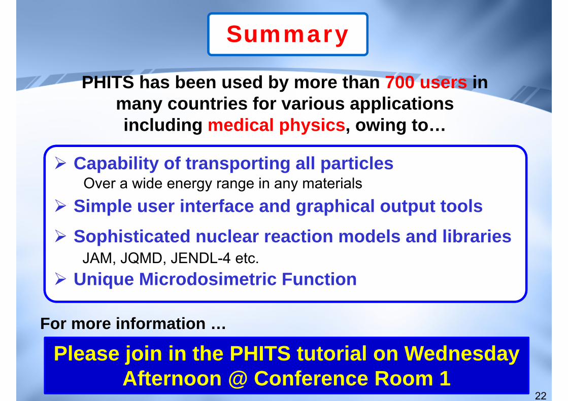
Summary
22
Capability of transporting all particles
Simple user interface and graphical output toolsSophisticated nuclear reaction models and libraries
Unique Microdosimetric FunctionJAM, JQMD, JENDL-4 etc.
Over a wide energy range in any materials
Please join in the PHITS tutorial on Wednesday Afternoon @ Conference Room 1
PHITS has been used by more than 700 users in many countries for various applications including medical physics, owing to…
For more information …