overview pbn procedure design · 2018-04-11 · icao gnss concept 7 pbn procedure design satellite...
TRANSCRIPT

PBN PROCEDURE DESIGN OVERVIEW
1
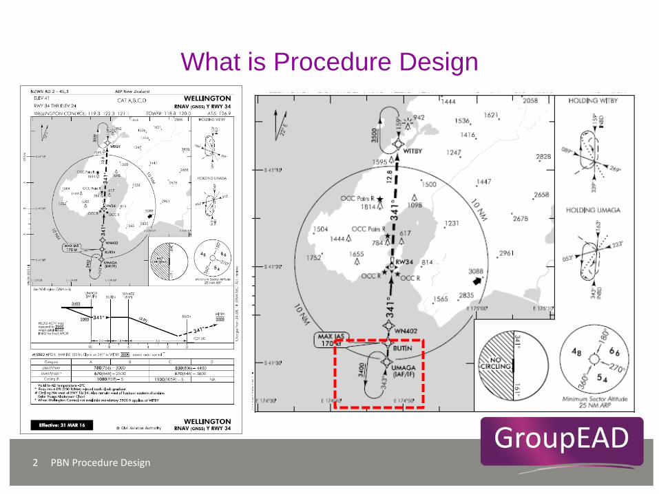
What is Procedure Design
PBN Procedure Design 2
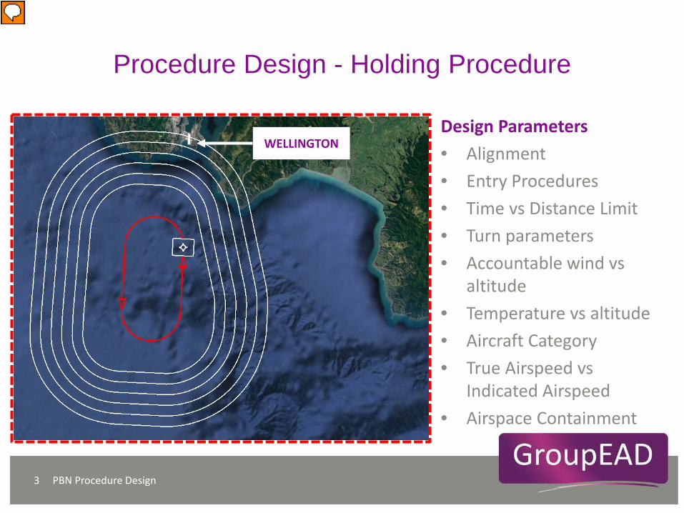
Procedure Design - Holding Procedure
PBN Procedure Design 3
Design Parameters • Alignment • Entry Procedures • Time vs Distance Limit • Turn parameters • Accountable wind vs
altitude • Temperature vs altitude • Aircraft Category • True Airspeed vs
Indicated Airspeed • Airspace Containment
WELLINGTON

Procedure Design - Holding Procedure
PBN Procedure Design 4
Obstacle Clearance
RNAV Principles 5
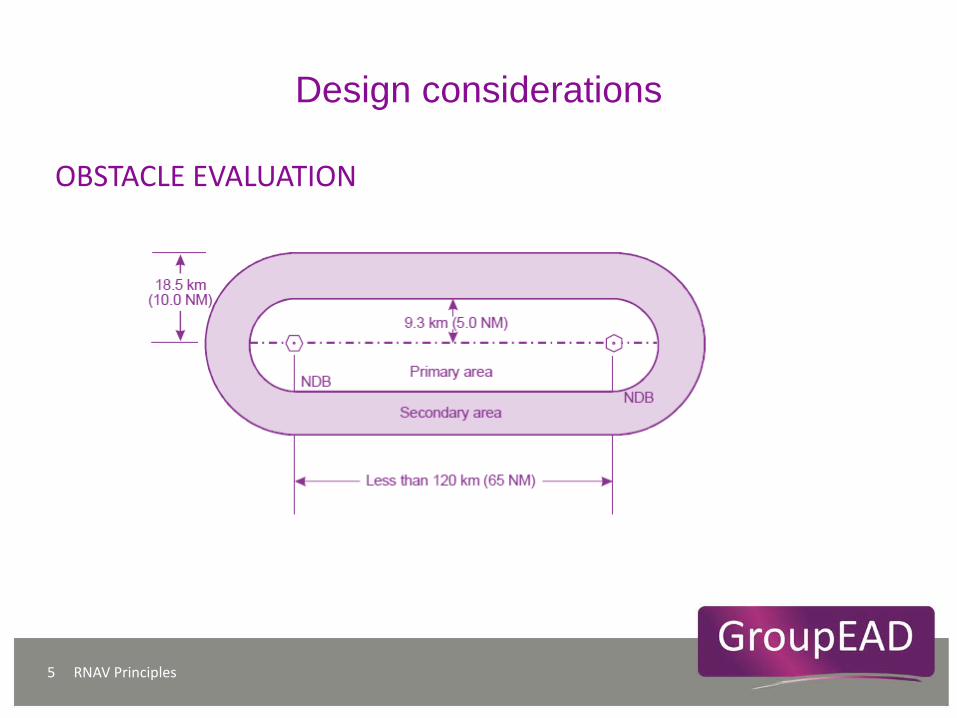
Design considerations
OBSTACLE EVALUATION

RNAV Principles 6
Design considerations
OBSTACLE EVALUATION
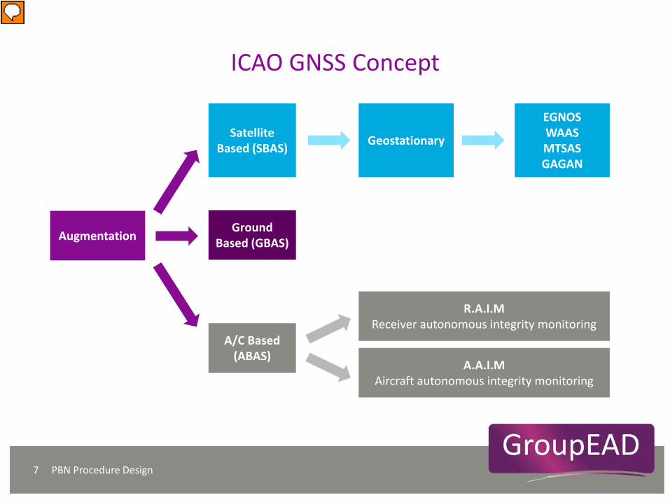
ICAO GNSS Concept
PBN Procedure Design 7
Satellite Based (SBAS)
Ground Based (GBAS)
A/C Based (ABAS)
Augmentation
Geostationary
EGNOS WAAS MTSAS GAGAN
R.A.I.M Receiver autonomous integrity monitoring
A.A.I.M Aircraft autonomous integrity monitoring
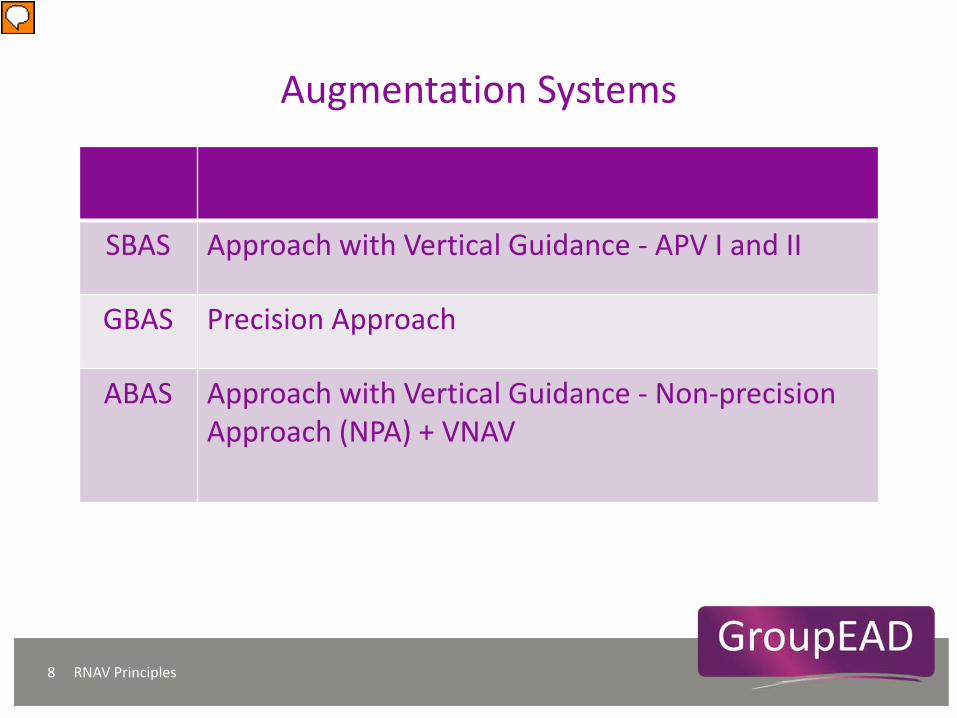
Augmentation Systems
RNAV Principles 8
SBAS Approach with Vertical Guidance - APV I and II
GBAS Precision Approach
ABAS Approach with Vertical Guidance - Non-precision Approach (NPA) + VNAV
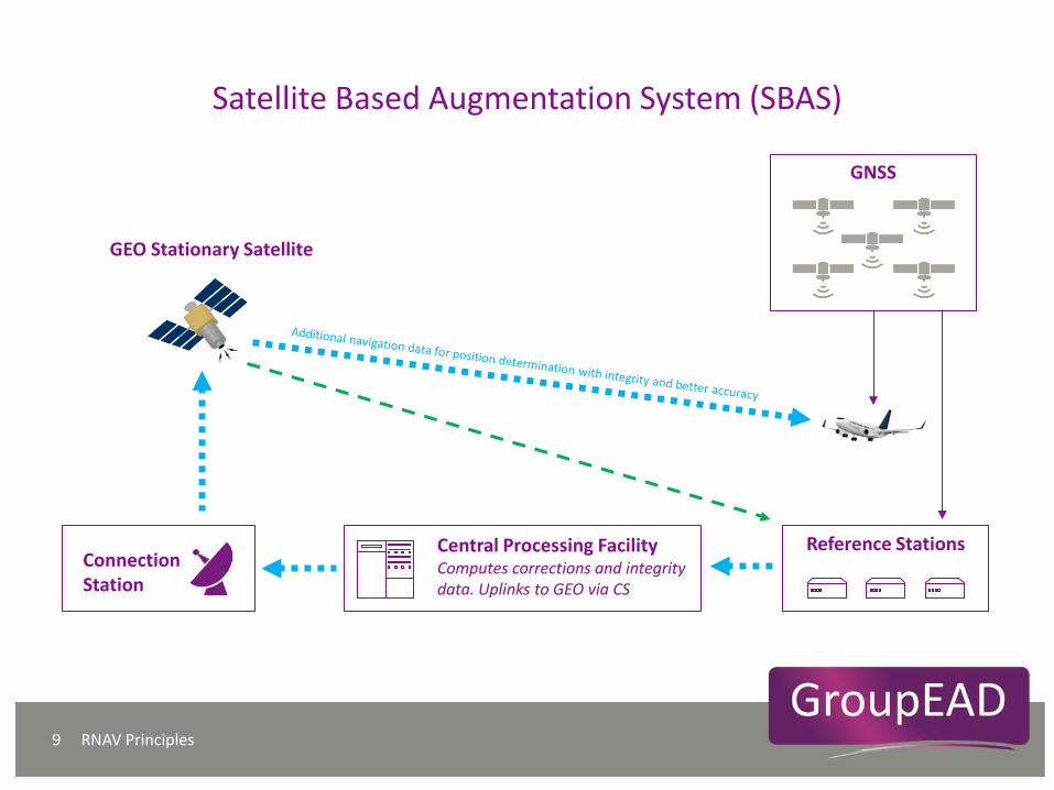
Satellite Based Augmentation System (SBAS)
RNAV Principles 9
Reference Stations
Central Processing Facility Computes corrections and integrity data. Uplinks to GEO via CS
Connection Station
GNSS
GEO Stationary Satellite
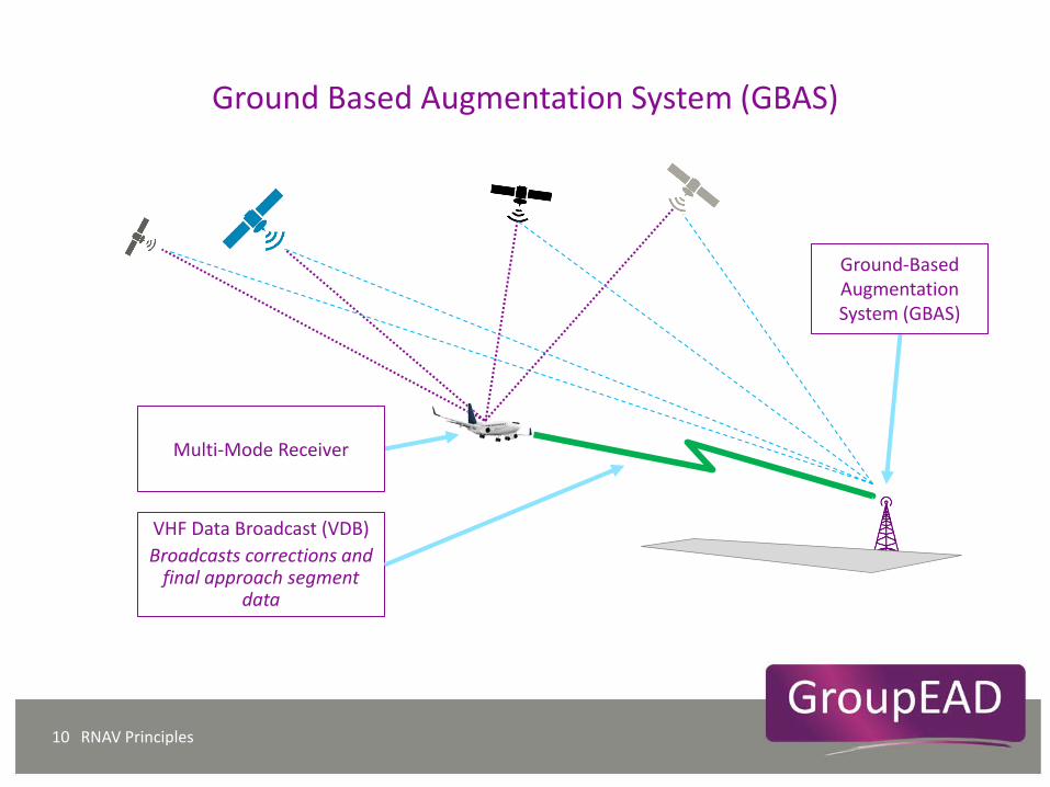
Ground Based Augmentation System (GBAS)
RNAV Principles 10
VHF Data Broadcast (VDB) Broadcasts corrections and
final approach segment data
Ground-Based Augmentation System (GBAS)
Multi-Mode Receiver
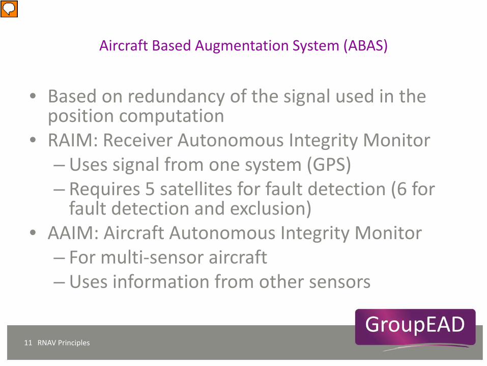
Aircraft Based Augmentation System (ABAS)
RNAV Principles 11
• Based on redundancy of the signal used in the position computation
• RAIM: Receiver Autonomous Integrity Monitor – Uses signal from one system (GPS) – Requires 5 satellites for fault detection (6 for
fault detection and exclusion) • AAIM: Aircraft Autonomous Integrity Monitor
– For multi-sensor aircraft – Uses information from other sensors

ICAO GNSS Concept
Integrity - the ability to provide timely warnings when the system is not safe to use. IMAL - Integrity Monitoring and Alarm Limit. The value depends of the phase of flight.
PBN Procedure Design 12
INTEGRITY
Accuracy of position
IMAL Value
GNSS position
GNSS position exclusion
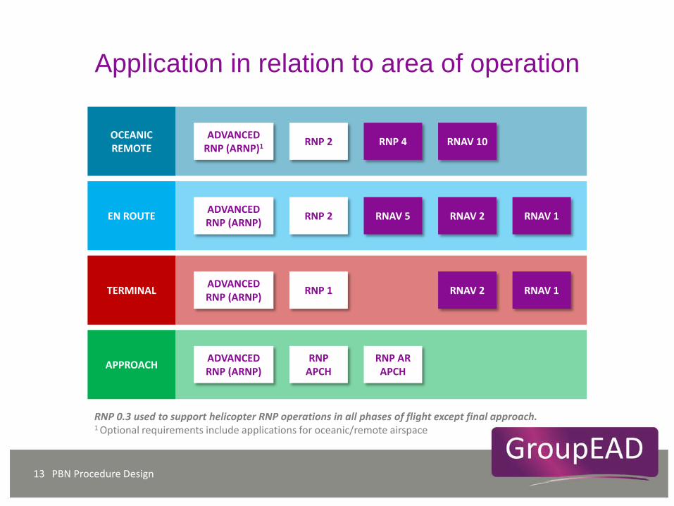
Application in relation to area of operation
PBN Procedure Design 13
OCEANIC REMOTE
EN ROUTE
TERMINAL
APPROACH
RNP 2
RNP 1
RNP APCH
RNP 4
RNAV 5
RNAV 2
RNP AR APCH
RNAV 2
RNAV 1
RNAV 1 ADVANCED RNP (ARNP)
RNAV 10
RNP 2
ADVANCED RNP (ARNP)
ADVANCED RNP (ARNP)
ADVANCED RNP (ARNP)1
RNP 0.3 used to support helicopter RNP operations in all phases of flight except final approach. 1 Optional requirements include applications for oceanic/remote airspace
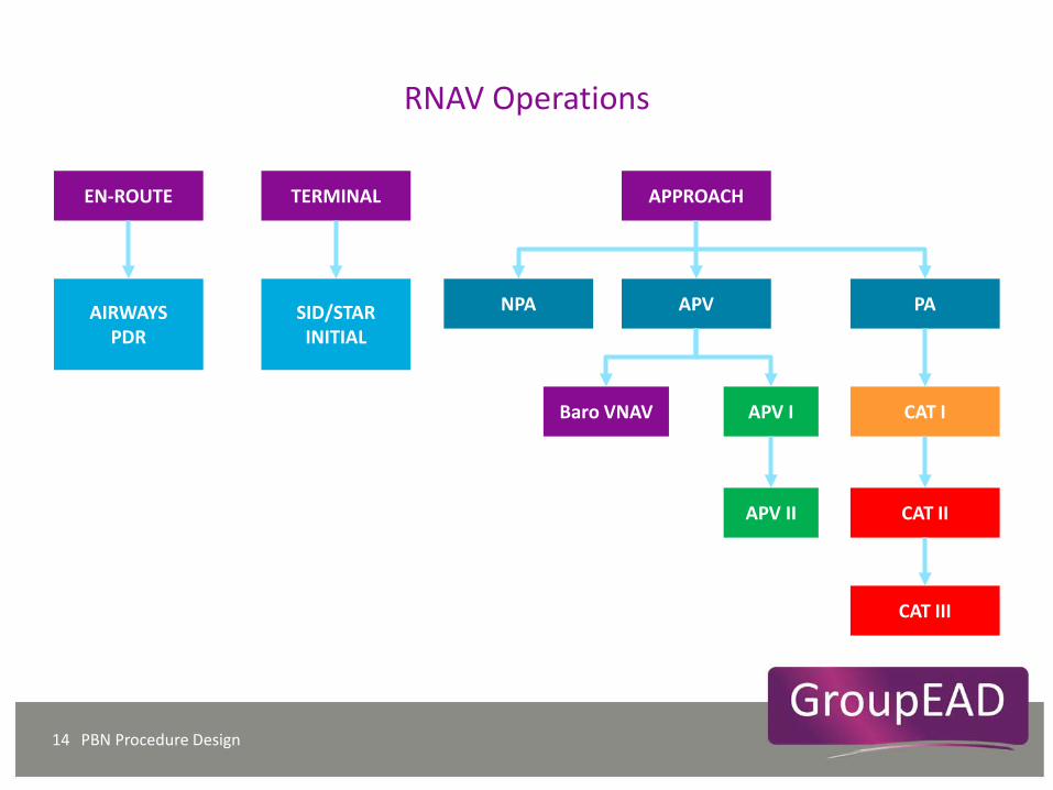
RNAV Operations
PBN Procedure Design 14
EN-ROUTE TERMINAL APPROACH
AIRWAYS PDR
SID/STAR INITIAL
NPA APV PA
APV I
APV II
Baro VNAV CAT I
CAT II
CAT III
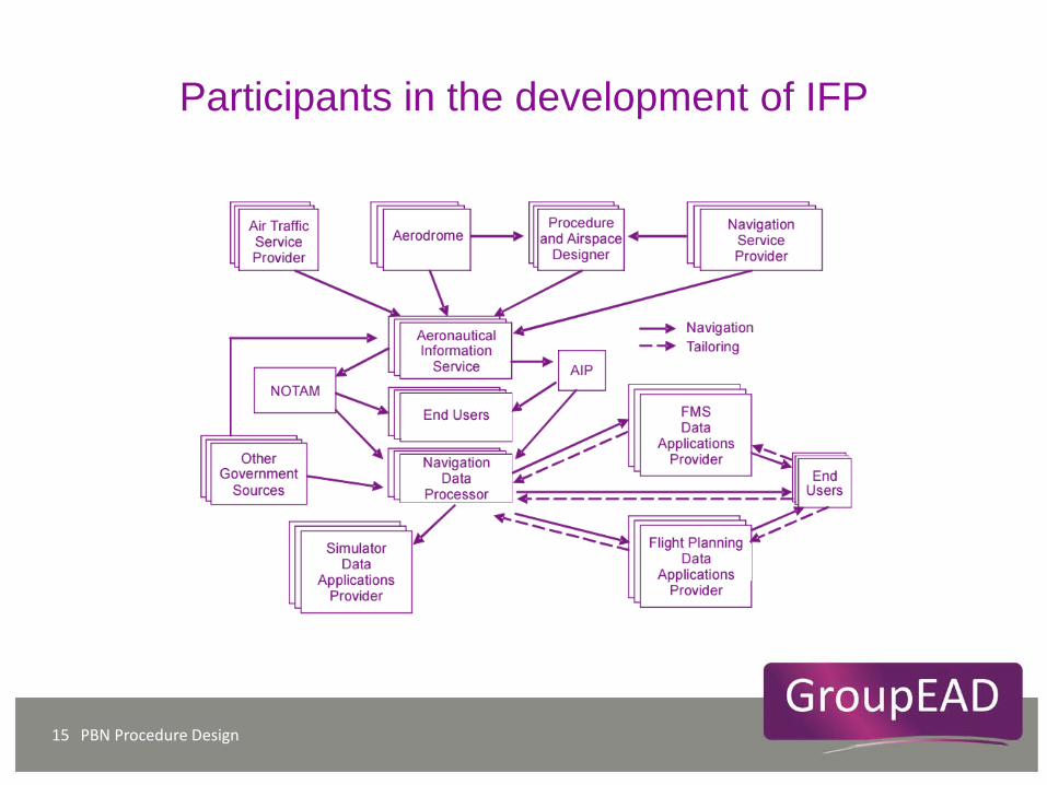
Participants in the development of IFP
PBN Procedure Design 15
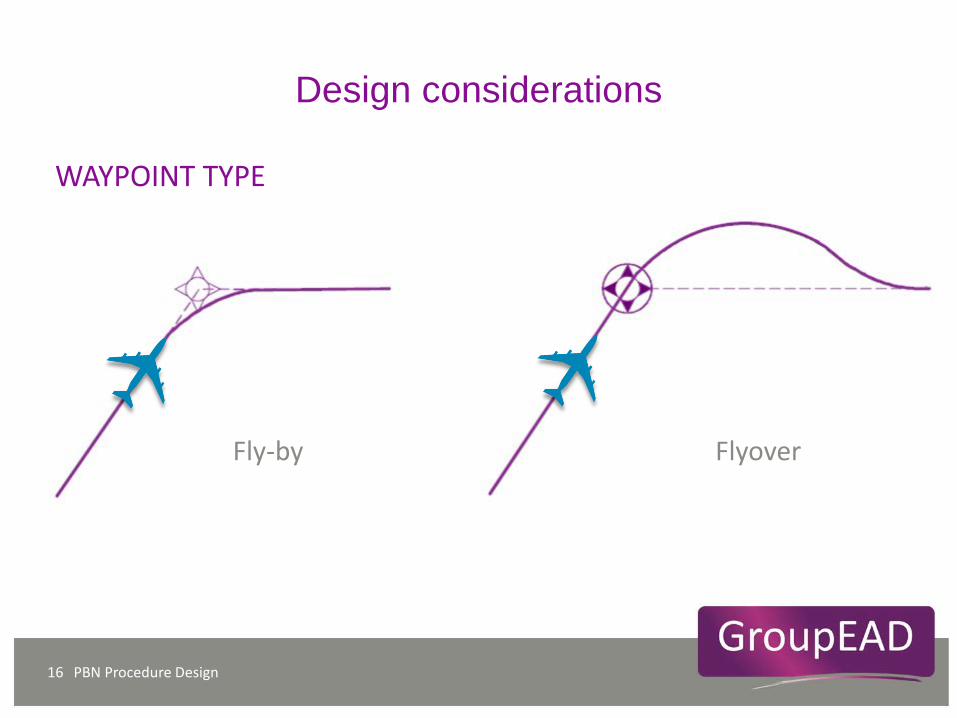
Design considerations
Fly-by
PBN Procedure Design 16
Flyover
WAYPOINT TYPE
Design considerations
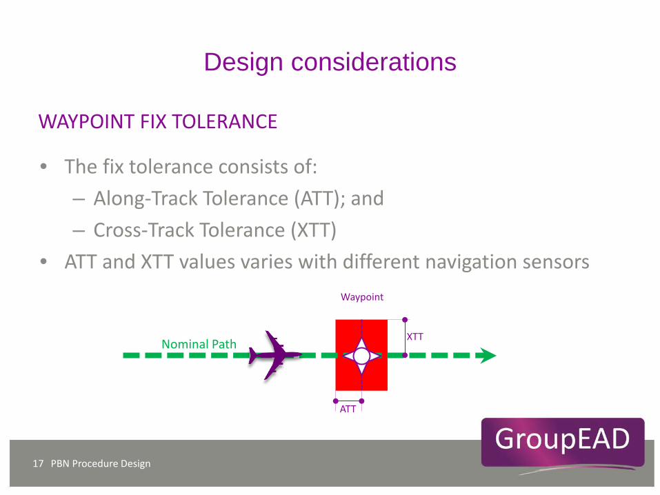
• The fix tolerance consists of: – Along-Track Tolerance (ATT); and – Cross-Track Tolerance (XTT)
• ATT and XTT values varies with different navigation sensors
PBN Procedure Design 17
XTT
ATT
Nominal Path
Waypoint
WAYPOINT FIX TOLERANCE
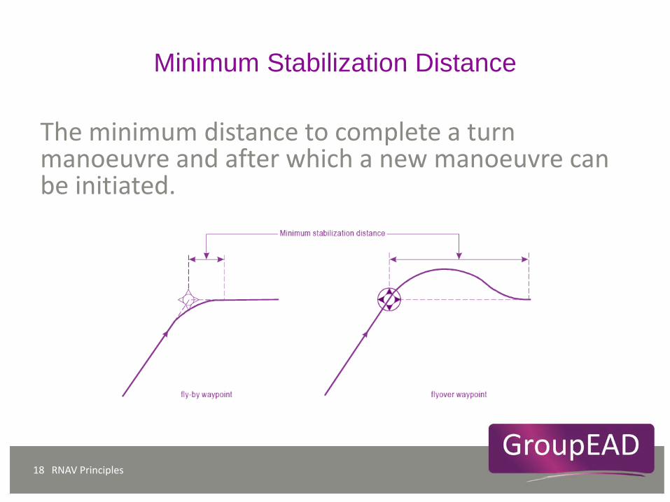
Minimum Stabilization Distance
RNAV Principles 18
The minimum distance to complete a turn manoeuvre and after which a new manoeuvre can be initiated.
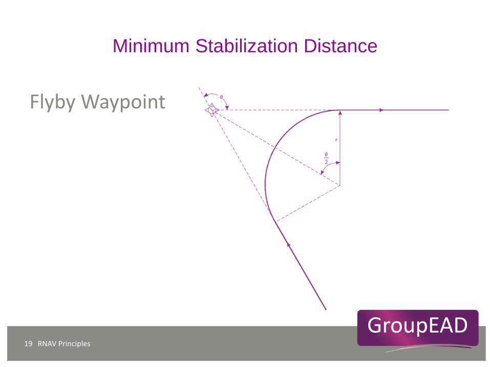
Minimum Stabilization Distance
RNAV Principles 19
Flyby Waypoint
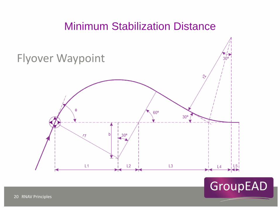
Minimum Stabilization Distance
RNAV Principles 20
Flyover Waypoint
Design considerations
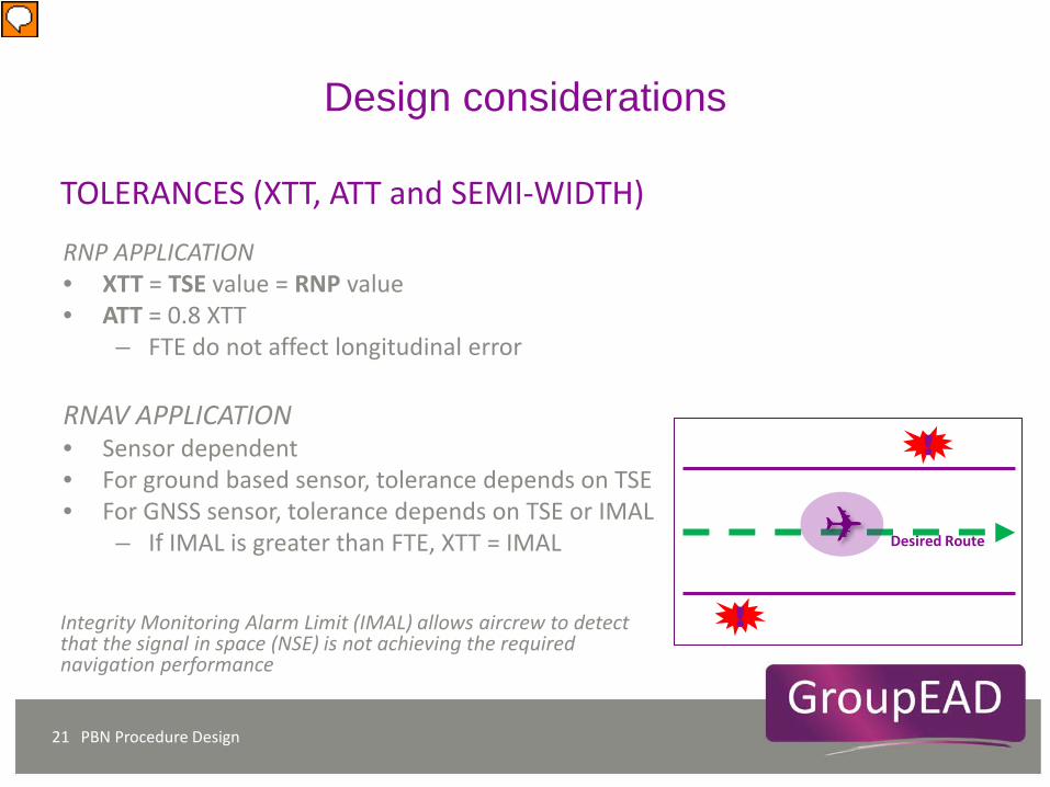
RNP APPLICATION • XTT = TSE value = RNP value • ATT = 0.8 XTT
– FTE do not affect longitudinal error RNAV APPLICATION • Sensor dependent • For ground based sensor, tolerance depends on TSE • For GNSS sensor, tolerance depends on TSE or IMAL
– If IMAL is greater than FTE, XTT = IMAL
PBN Procedure Design 21
TOLERANCES (XTT, ATT and SEMI-WIDTH)
Integrity Monitoring Alarm Limit (IMAL) allows aircrew to detect that the signal in space (NSE) is not achieving the required navigation performance
Desired Route
!
!

Design considerations
PBN Procedure Design 22
Area Width for RNP application
NAV SPEC + SENSOR ATT, XTT, BV PROTECTION
AREA WIDTH RNP
Area Width for RNAV application
NAV SPEC + SENSOR ATT, XTT, BV PROTECTION
AREA WIDTH
AREA WIDTH

Design considerations
RNAV Arrivals 23
ALIGNMENT

RNAV Principles 24
• Descent Gradient = Δh/TRD
• 𝑇𝑇𝑇𝑇𝑇𝑇 = 𝑇𝑇 − 𝑟𝑟1 tan θ12
− 𝑟𝑟2 tan θ22
+ 𝑟𝑟1π180
× θ12
+ 𝑟𝑟2π180
× θ22
Where: D = segment length Θ1 = turn angle (degrees) at the beginning of the segment Θ2 = turn angle (degrees) at the end of the segment r1 = turn radius at the beginning of the segment r2 = turn radius at the end of the segment
IAF
IF
FAF
𝑟𝑟2
𝑟𝑟1
θ1
2
θ2
2 Θ2
Θ1
Design considerations
DESCENT GRADIENT

RNAV Principles 25
MOC
MOC
SEGMENT OCA
OCA/H
IF FAF
PROCEDURE ALTITUDE
Design considerations
OBSTACLE EVALUATION
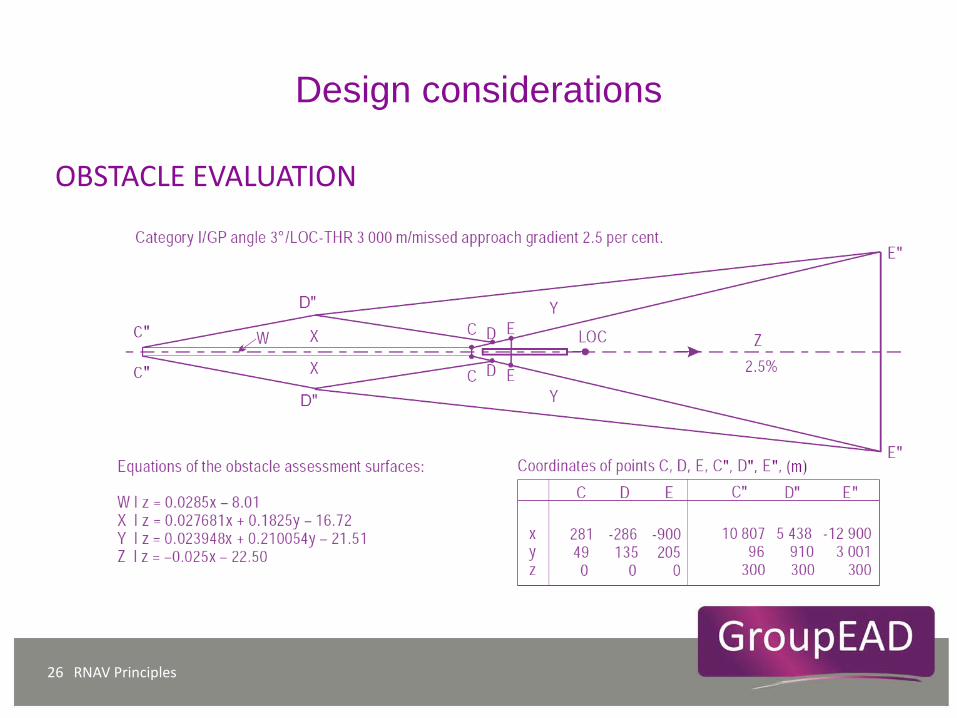
RNAV Principles 26
Design considerations
OBSTACLE EVALUATION
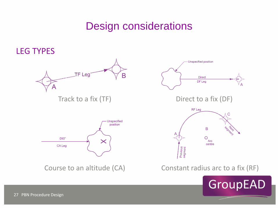
Track to a fix (TF) Direct to a fix (DF)
Course to an altitude (CA) Constant radius arc to a fix (RF)
Design considerations
PBN Procedure Design 27
LEG TYPES
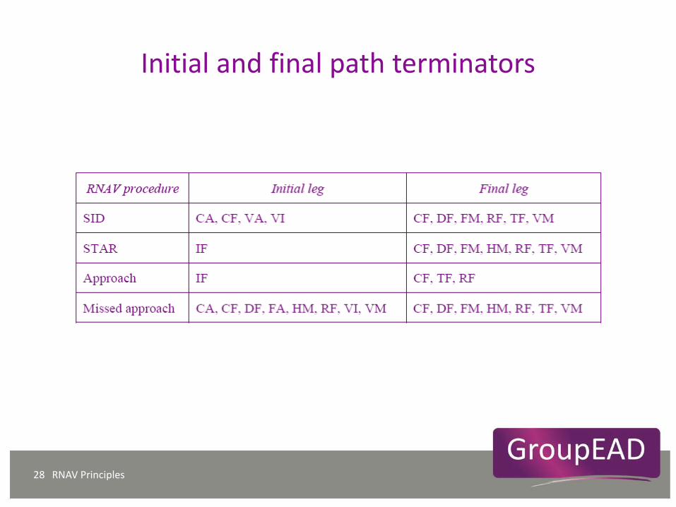
Initial and final path terminators
RNAV Principles 28
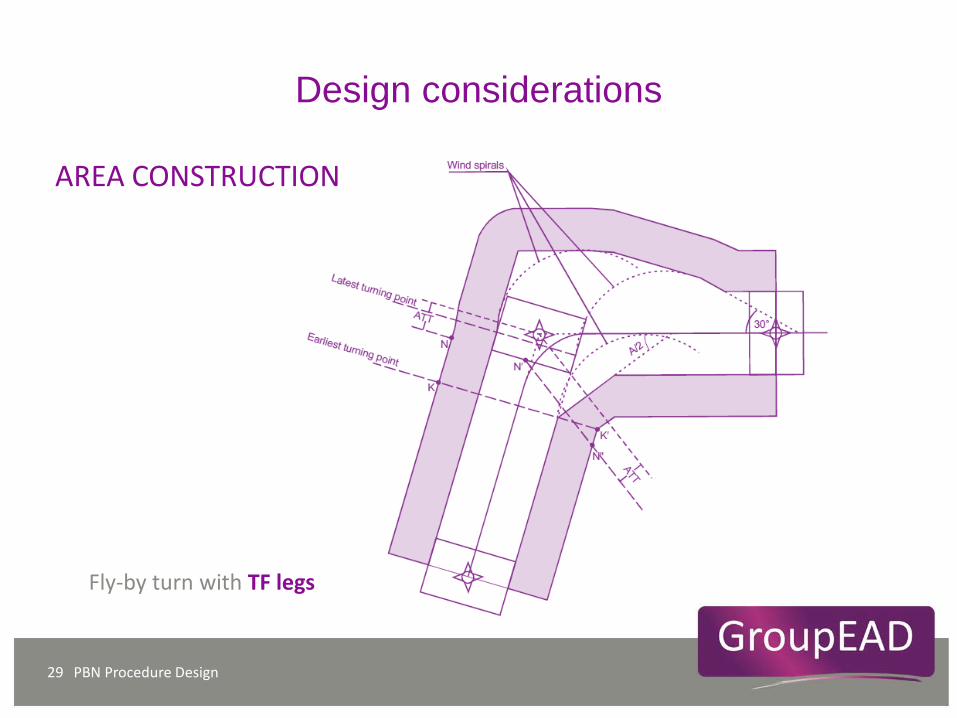
PBN Procedure Design 29
Fly-by turn with TF legs
Design considerations
AREA CONSTRUCTION
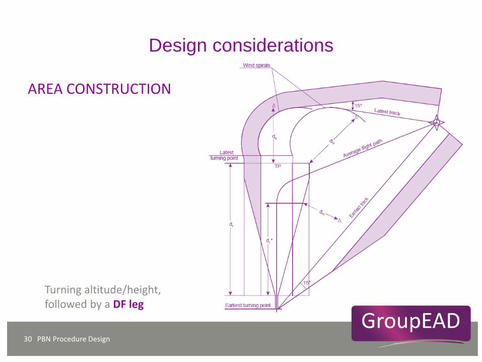
PBN Procedure Design 30
Turning altitude/height, followed by a DF leg
Design considerations
AREA CONSTRUCTION
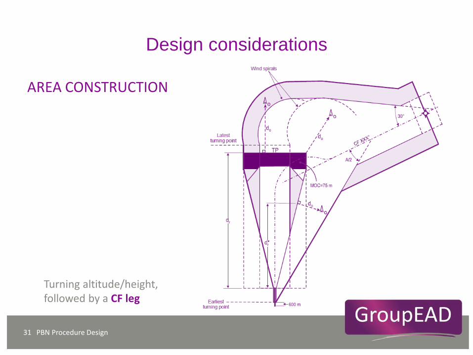
PBN Procedure Design 31
Turning altitude/height, followed by a CF leg
Design considerations
AREA CONSTRUCTION
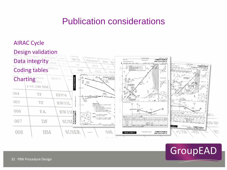
Publication considerations
PBN Procedure Design 32
AIRAC Cycle Design validation Data integrity Coding tables Charting

PBN Procedure Design 33
Thank You

Departure
PBN Procedure Design 34
Design considerations
AREA CONSTRUCTION

PBN Procedure Design 35
Flyover turn with a TF leg after the turn
Design considerations
AREA CONSTRUCTION
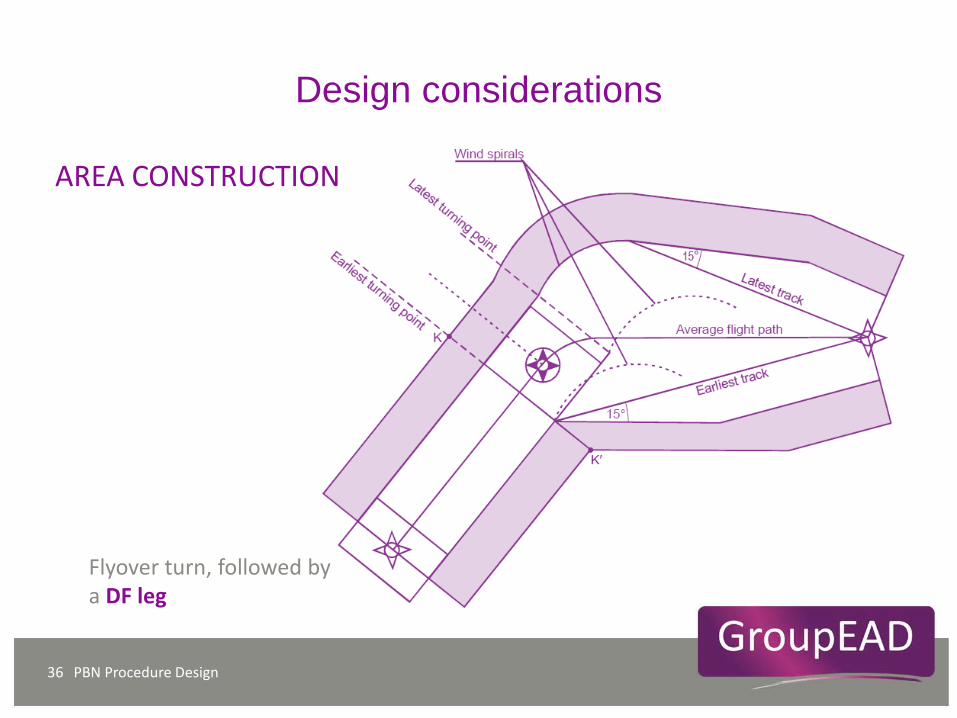
PBN Procedure Design 36
Flyover turn, followed by a DF leg
Design considerations
AREA CONSTRUCTION
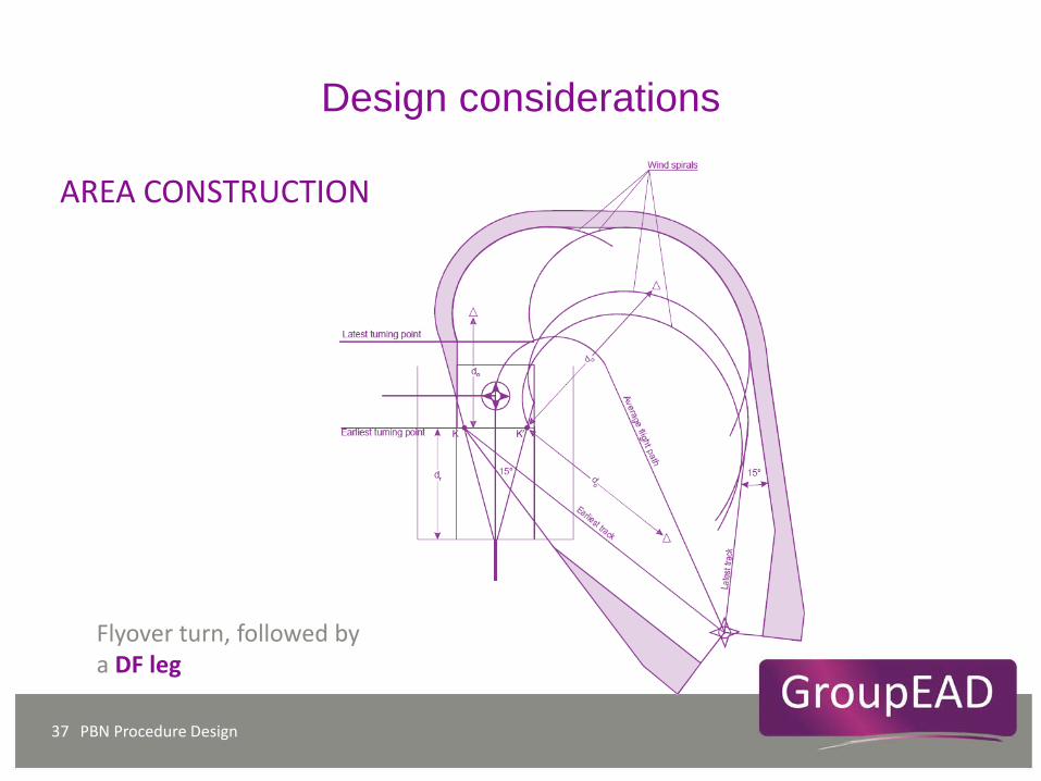
PBN Procedure Design 37
Flyover turn, followed by a DF leg
Design considerations
AREA CONSTRUCTION
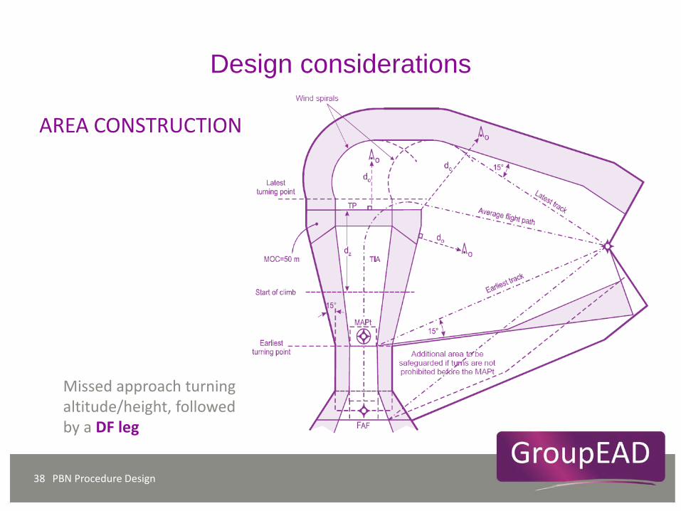
PBN Procedure Design 38
Missed approach turning altitude/height, followed by a DF leg
Design considerations
AREA CONSTRUCTION
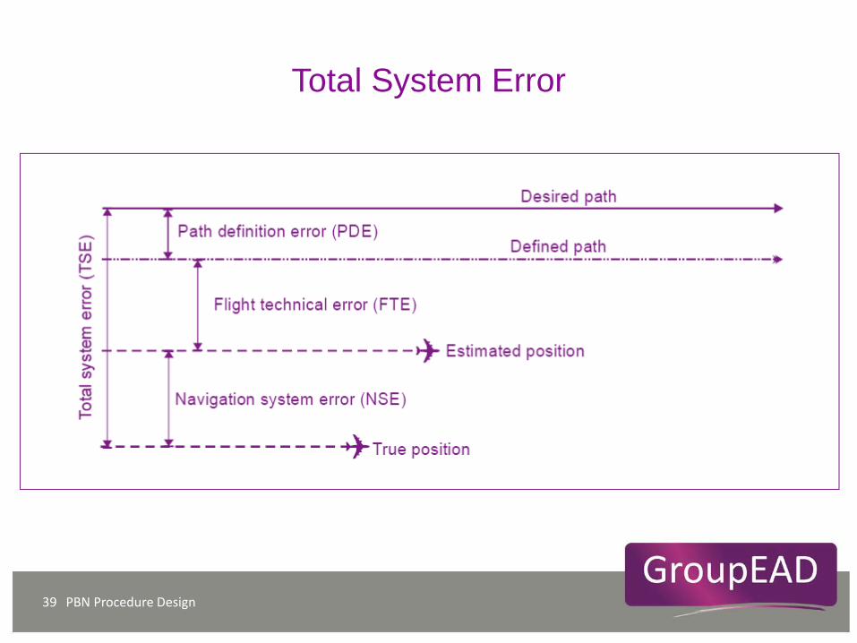
PBN Procedure Design 39
Total System Error
AREA CONSTRUCTION
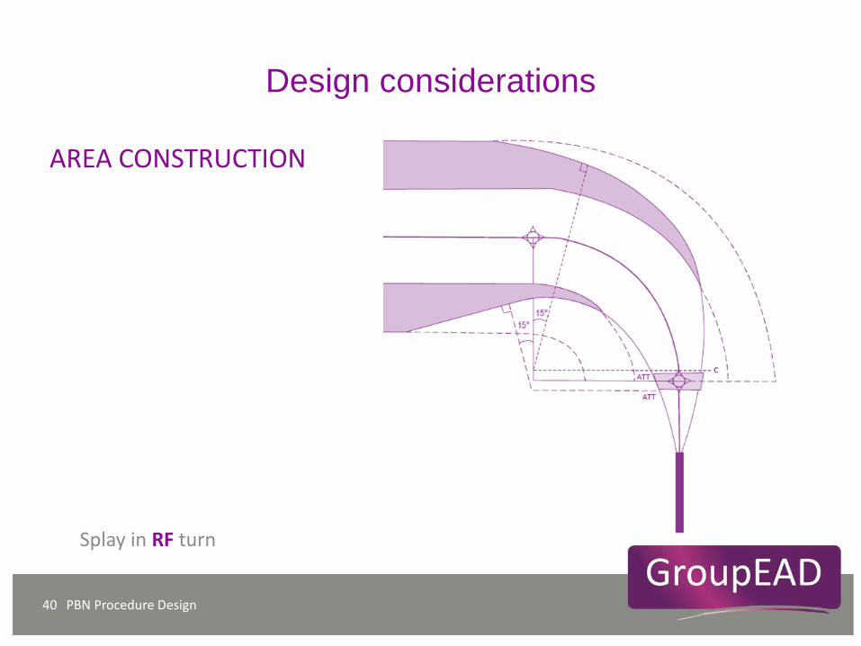
PBN Procedure Design 40
Splay in RF turn
Design considerations
AREA CONSTRUCTION
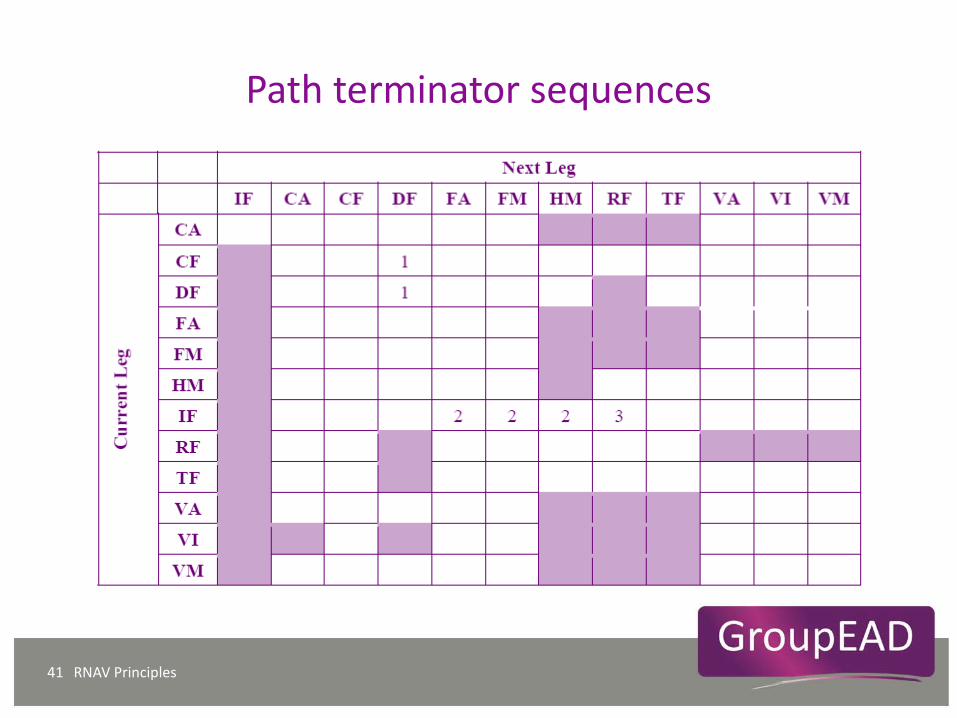
Path terminator sequences
RNAV Principles 41