overview table of contents - brunel university londonemstaam/material/bit/labview week...
TRANSCRIPT
Week 3
Exercice 1:
Source: http://www.ni.com/white-paper/7595/en/
Overview
The state machine is one of the fundamental architectures NI LabVIEW developers
frequently use to build applications quickly. Developers use state machines in applications
where distinguishable states exist. Each state can lead to one or multiple states and can end
the process flow. A state machine relies on user input or in-state calculation to determine
which state to go to next. Many applications require an “initialize” state followed by a default
state, where you can perform many different actions. These actions depend on previous and
current inputs as well as states. You can use a “shutdown” state to perform cleanup actions.
Table of Contents
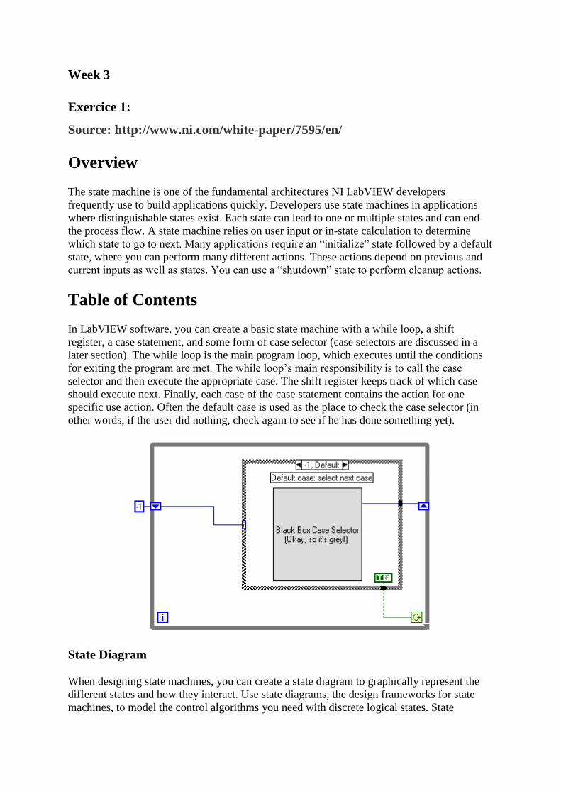
In LabVIEW software, you can create a basic state machine with a while loop, a shift
register, a case statement, and some form of case selector (case selectors are discussed in a
later section). The while loop is the main program loop, which executes until the conditions
for exiting the program are met. The while loop’s main responsibility is to call the case
selector and then execute the appropriate case. The shift register keeps track of which case
should execute next. Finally, each case of the case statement contains the action for one
specific use action. Often the default case is used as the place to check the case selector (in
other words, if the user did nothing, check again to see if he has done something yet).
State Diagram
When designing state machines, you can create a state diagram to graphically represent the
different states and how they interact. Use state diagrams, the design frameworks for state
machines, to model the control algorithms you need with discrete logical states. State
Diagrams make it easy to develop and understand the functionality of an application that uses
a state machine.
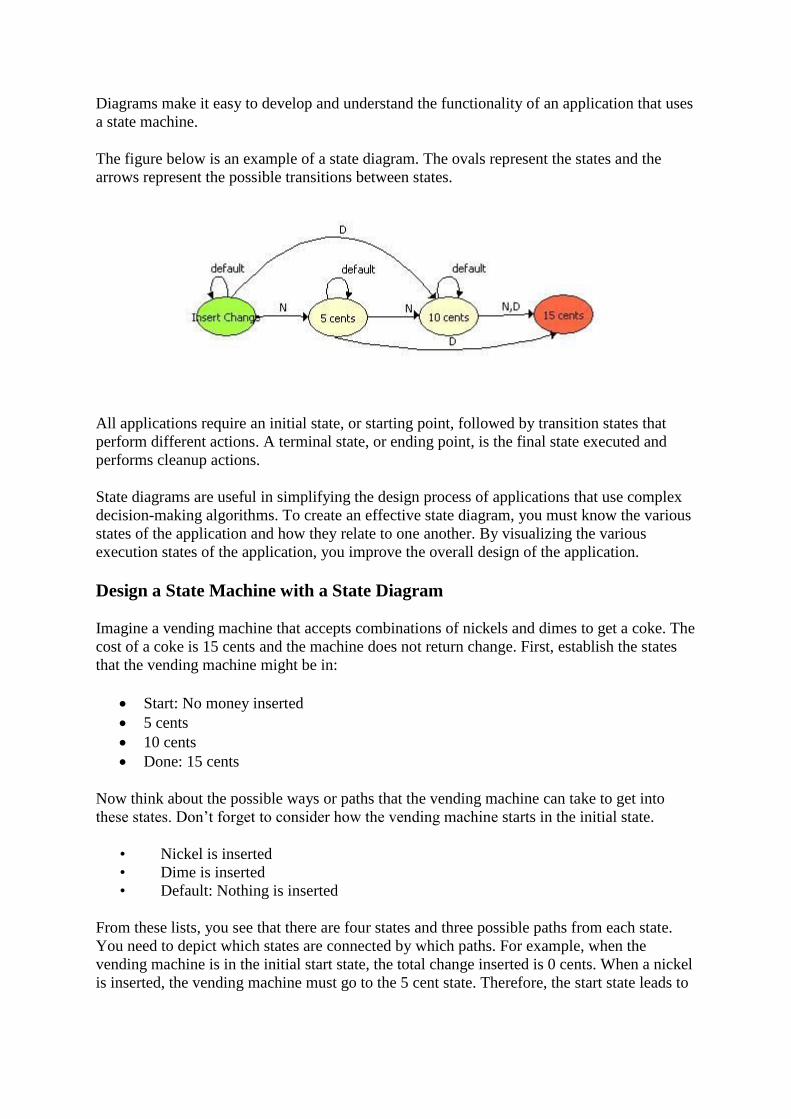
The figure below is an example of a state diagram. The ovals represent the states and the
arrows represent the possible transitions between states.
All applications require an initial state, or starting point, followed by transition states that
perform different actions. A terminal state, or ending point, is the final state executed and
performs cleanup actions.
State diagrams are useful in simplifying the design process of applications that use complex
decision-making algorithms. To create an effective state diagram, you must know the various
states of the application and how they relate to one another. By visualizing the various
execution states of the application, you improve the overall design of the application.
Design a State Machine with a State Diagram
Imagine a vending machine that accepts combinations of nickels and dimes to get a coke. The
cost of a coke is 15 cents and the machine does not return change. First, establish the states
that the vending machine might be in:
Start: No money inserted
5 cents
10 cents
Done: 15 cents
Now think about the possible ways or paths that the vending machine can take to get into
these states. Don’t forget to consider how the vending machine starts in the initial state.
• Nickel is inserted
• Dime is inserted
• Default: Nothing is inserted
From these lists, you see that there are four states and three possible paths from each state.
You need to depict which states are connected by which paths. For example, when the
vending machine is in the initial start state, the total change inserted is 0 cents. When a nickel
is inserted, the vending machine must go to the 5 cent state. Therefore, the start state leads to

the 5 cent state by the nickel path. By considering all states and paths, you can create a state
diagram for the vending machine:
With a state diagram, you can better understand how to create a state machine.
Building a State Machine
Using the state diagram above, create a state machine.
1. Create a new blank VI.
2. on the front panel place:
• Two text buttons named “Nickel” and “Dime”
• Text indicator named “Money Deposited”
• Boolean indicator named “Dispense coke”
3. Place a while loop on the block diagram.
4. Place a case structure in the while loop.

5. Create a shift register on the while loop.
6. Create an Enum and wire it to the shift register to initialize it.
7. Right-click the Enum, select Edit Items, and add the following “states”:
• Start
• 5 cents
• 10 cents
• Dispense
8. Wire the shift register to the conditional input of the case structure.
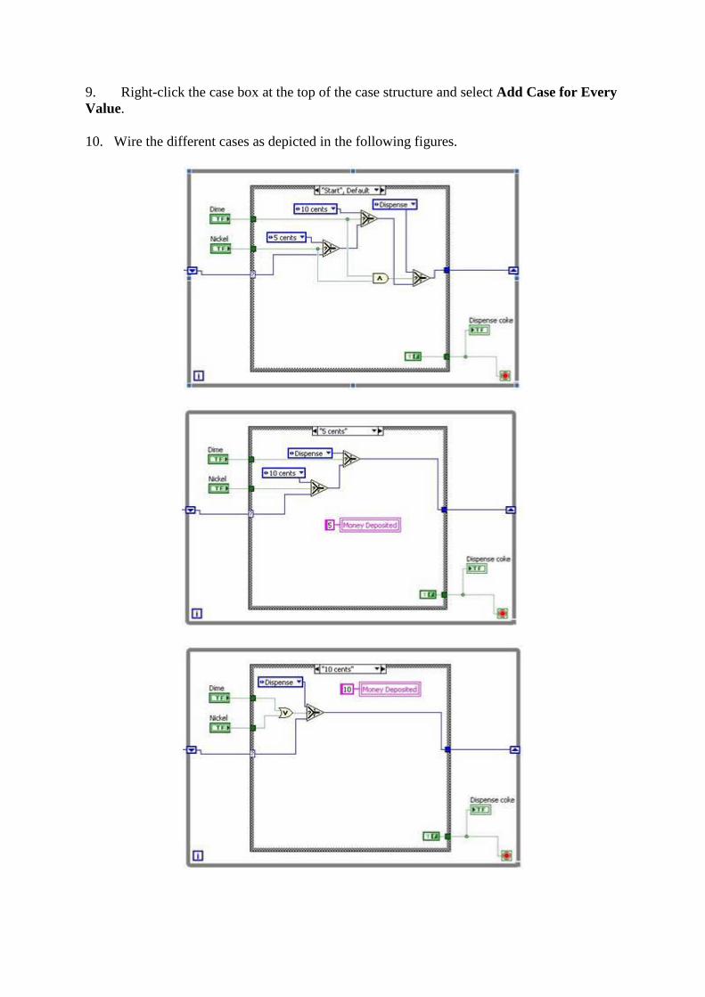
9. Right-click the case box at the top of the case structure and select Add Case for Every
Value.
10. Wire the different cases as depicted in the following figures.
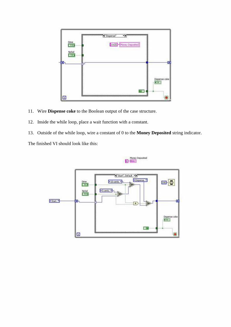
11. Wire Dispense coke to the Boolean output of the case structure.
12. Inside the while loop, place a wait function with a constant.
13. Outside of the while loop, wire a constant of 0 to the Money Deposited string indicator.
The finished VI should look like this:
Exercise 2:
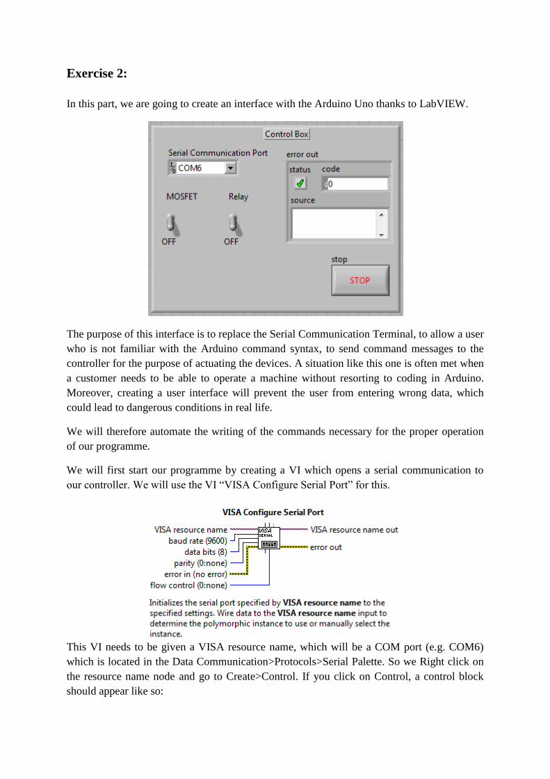
In this part, we are going to create an interface with the Arduino Uno thanks to LabVIEW.
The purpose of this interface is to replace the Serial Communication Terminal, to allow a user
who is not familiar with the Arduino command syntax, to send command messages to the
controller for the purpose of actuating the devices. A situation like this one is often met when
a customer needs to be able to operate a machine without resorting to coding in Arduino.
Moreover, creating a user interface will prevent the user from entering wrong data, which
could lead to dangerous conditions in real life.
We will therefore automate the writing of the commands necessary for the proper operation
of our programme.
We will first start our programme by creating a VI which opens a serial communication to
our controller. We will use the VI “VISA Configure Serial Port” for this.
This VI needs to be given a VISA resource name, which will be a COM port (e.g. COM6)
which is located in the Data Communication>Protocols>Serial Palette. So we Right click on
the resource name node and go to Create>Control. If you click on Control, a control block
should appear like so:

Rename this block to “Serial Communication Port”. You can also set the baud rate to 9600 by
right-clicking on the input “baud rate”, and then Create>Constant and setting it to 9600.
Now we must open the communication that we have configured, which is the role of the VI
“VISA Open”:
This VI can be found by pressing Ctrl + Space and typing “VISA Open”, or by looking for
the Instrument I/O>VISA> VISA Advanced palette as shown below:
We will then create an Event Structure inside a while loop and add a “VISA close” VI which
will close the serial communication port when we will press the stop button.

On the front panel, two toggle switches will be added, one of them will be named
“MOSFET” and the other one “Relay”, the toggle switches can be found in the Buttons
palette.
We will then Add 3 Event cases to the Event structure:
1. Add one event case for the toggle switch MOSFET: Value change
2. Add one event case for the toggle switch Relay: Value change
3. Add one event case for the button STOP: Value change
The code inside the event case will be executed every time its respective toggle switch or
button is actuated.
Event case “MOSFET: Value Change”
In this event case, we want to send a message to the Arduino to switch on or off the MOSFET
module.
The value of the MOSFET toggle switch is accessed by the “NewVal” terminal of the event
structure. On the other hand, the value of the toggle switch Relay is accessed using a Local
Variable.

To create a Local Variable, hit Ctrl+Space and search for Local Variable…
A block like this should appear. Right click on it and select “Change to read” (1). You
will see the arrow moving to the right in the clock label (2). Then left click on the amended
block and select Relay (3). The local variable will be set to the value of the toggle switch
Relay.
Since the buttons and switches have a Boolean data type (eg TRUE/FALSE) in LabVIEW,
we use a “Boolean To (0,1)” VI to convert the Boolean values into integer values.
Note: The color of the wires change according to the type of data they contain, wire wired to
a Boolean input/output will always be green.
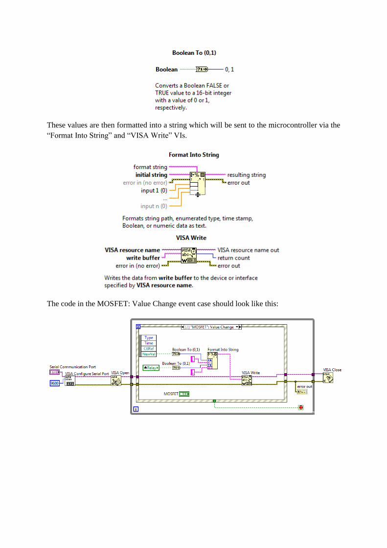
These values are then formatted into a string which will be sent to the microcontroller via the
“Format Into String” and “VISA Write” VIs.
The code in the MOSFET: Value Change event case should look like this:

Event case: “Relay: Value change”
In this event case, we want to send a message to the Arduino to switch on or off the Relay
module. Since the buttons and switches have a Boolean data type (e.g. TRUE/FALSE) in
LabVIEW, we use a “Boolean To (0,1)” VI to convert the Boolean values into integer values.
As you can see, the structure of the code is very similar to what we have previously seen for
the event case “MOSFET: Value change”, and should look like this:
Event case: “STOP: Value change”
This event case is very simple: simply move the STOP button inside the event case structure
and wire its output to the conditional terminal of the While loop. This will terminate the
while loop and close our programme.
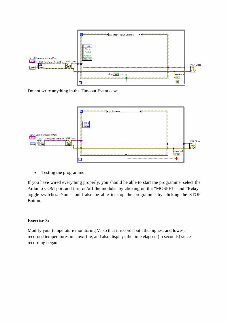
Do not write anything in the Timeout Event case:
Testing the programme
If you have wired everything properly, you should be able to start the programme, select the
Arduino COM port and turn on/off the modules by clicking on the “MOSFET” and “Relay”
toggle switches. You should also be able to stop the programme by clicking the STOP
Button.
Exercise 3:
Modify your temperature monitoring VI so that it records both the highest and lowest
recorded temperatures in a text file, and also displays the time elapsed (in seconds) since
recording began.

Exercise 4:
Build the following block diagram.
Display the front panel and run the VI. The graph displays both the temperature data and best
fit curve of the temperature waveform. Try different values for the polynomial order constant
on the block diagram and run the VI again.
Exercise 5:
Create a VI that have a control array of clusters called People on its front panel with the
elements Name and Age. An indicator of the exact same type should also appear on the front
panel called Filtered People. Two buttons named Filter and Quit should be placed on the front
panel as well. Finally, a cluster called Filter by age should be shown on the front panel
containing two numeric controls called Upper age and Lower age. When run, the VI should
repeatedly check to see if any user input has occurred. The VI should respond to a press of

the quit button by appropriately stopping the VI. The VI should respond to a press of the filter
button by finding all of the elements in the people array that fall within the age limits. The
people that match the age criteria should be displayed in the Filtered People array.
Hint: This project makes use of many of the topics discussed so far including the use of a
while-loop, an event structure, a for-loop in a for-each configuration, an indexing tunnel, and
shift registers.