owner' s manual - infocenter.buggypartsnw.com filethank you for purchasing our kart. we hope...
TRANSCRIPT


OWNER' S MANUAL Page1. FOREWORD ------------------------------------------------------------------------------------------ 12. A FEW WORDS ABOUT SAFETY ------------------------------------------------------------- 23. IMPORTANT SAFETY INFORMATION------------------------------------------------------- 34. SAFETY LABELS----------------------------------------------------------------------------------- 55. ARE YOU READY TO DRIVE?----------------------------------------------------------------- 66. IS YOUR VEHICLE READY TO DRIVE?----------------------------------------------------- 77. SAFE DRIVING PRECAUTIONS--------------------------------------------------------------- 88. P.D.I.---------------------------------------------------------------------------------------------------- 109. SPECIFICATIONS---------------------------------------------------------------------------------- 1110. OPERATION---------------------------------------------------------------------------------------- 1311. SERVICE INSTRUCTIONS--------------------------------------------------------------------- 1712. REPAIR---------------------------------------------------------------------------------------------- 2013. PERIODICAL CHECK AND SERVICES---------------------------------------------------- 2314. WIRING DIAGRAM ------------------------------------------------------------------------------ 23
PARTS MANUAL Figure1. CYLINDER COMP.--------------------------------------------------------------------------------- Fig. 12. CYLINDER COVER ASSY.(1)-------------------------------------------------------------------- Fig. 23. CYLINDER COVER ASSY.(2)-------------------------------------------------------------------- Fig. 34. CRANKCASE ASSY.------------------------------------------------------------------------------- Fig. 45. RIGHT SIDE COVER ASSY.--------------------------------------------------------------------- Fig. 56. CRANKSHAFT CON'ROD & PISTON ASSY.------------------------------------------------ Fig. 67. VALVE TRANNYASSY.(1)--------------------------------------------------------------------------Fig. 78. VALVE TRANNY ASSY.(2)------------------------------------------------------------------------ Fig. 89. LEFT SIDE COVER ASSY.----------------------------------------------------------------------- Fig. 910. WATER PUMP ASSY.---------------------------------------------------------------------------- Fig. 1011. CARBURETOR COMP.--------------------------------------------------------------------------- Fig.1112. OIL PUMP ASSY.---------------------------------------------------------------------------------- Fig.1213. CLUTCH ASSY.------------------------------------------------------------------------------------ Fig. 1314. ELECTRIC STARTER ASSY.------------------------------------------------------------------- Fig.1415. REDUCTION BOX ASSY.----------------------------------------------------------------------- Fig.1516. GEARBOX ASSY.--------------------------------------------------------------------------------- Fig.1617. MAGNETO COMP.-------------------------------------------------------------------------------- Fig.1718. FRAME GROUP----------------------------------------------------------------------------------- Fig.1819. STEERING SHAFT ASSY.---------------------------------------------------------------------- Fig.1920. FRONT SUSPENSION ARM ASSY----------------------------------------------------------- Fig.2021. FULL SHIFTING ASSY.------------------------------------------------------------------------- Fig.2122. REAR CARGO RACK/ SEAT/ BELT---------------------------------------------------------- Fig.2223. AIR CLEANER/ RADIATOR/ BATTERY/ MUFFLER ASSY.---------------------------- Fig.2324. GEAR BOX ASSY.-------------------------------------------------------------------------------- Fig.2425. REAR SUSPENSION ASSY------------------------------------------------------------------- Fig.2526. WIRE HARNESS/ELECTRICAL -------------------------------------------------------------- Fig.2627. WARNING STICKERS -------------------------------------------------------------------------- Fig.27

Thank you for purchasing our kart. We hope you will enjoy it. Before you start to operate the kart, please read through this Owner's Manual carefully as it contains important safety and maintenance information. Failure to follow the warnings contained in this manual can result in serious injuries or death.
Be sure to follow the recommended maintenance schedule and service your kart accordingly. Preventive maintenance is extremely important to the longevity of your kart.
Beginners should seek instruction from their dealer or qualified instructors before and during initial use of the kart. It is also recommended to practice in a large flat open area to familiarize yourself with operations of this kart.
We hope you will have a pleasant experience with our products and thank you again for choosing our kart.

A FEW WORDS ABOUT SAFETY
In order to keep everyone safe, you must take responsibility for the safe operation of your kart.
To help you make informed decisions about safety, we have provided operating procedures and other information on labels and in this manual. This information alerts you to potential hazards that could hurt you or others.
It is not practical or possible to warn you about all hazards associated with operating or maintaining a kart. You must use your own good judgment.
You will find important safety information in a variety of forms, including:
Safety Labels - On the kart.
Safety Messages - Preceeded by a safety alert symbol and one of two signalwords: WARNING, or CAUTION. These signal words mean:
Physical harm may result from failure to adhere to the instructions that are described within the WARNING labels.
Safety Headings — such as Important Safety Reminders or Important Safety Precautions.
Safety Section — such as kart safety.
Instructions — how to use this kart correctly and safely.
This entire manual is filled with important safety information—please read it all carefully.

IMPORTANT SAFETY INFORMATION
Your kart will provide you with many years of use and pleasure. Providing you take responsibility for your
own safety and that of any one else using your kart or near to the kart when it is being used and understand
the challenges you can meet while driving.
There is much that you can do to protect yourself while operating your kart. You will find many helpful
recommendations throughout this manual. The following are a few that we consider to be the most
important.
Follow the Age Recommendation
The kart should not be driven by anyone under the age of 16.
Always Wear a Helmet
It's a proven fact: helmets significantly reduce the number and severity of head injuries. Always wear an
approved motorcycle helmet. We also recommend that you wear eye protection, sturdy boots, gloves, and
other protective gear.
Drive Off-Road Only
Your kart is designed and manufactured for off-road use only. The tires are not made for use on
pavements, and the kart does not have turn signals and other features required for use on public roads. If
you need to cross a paved or public road, get off and walk your kart across.
Take Time to Learn & Practice
Even if you have driven other karts, take time to become familiar with how this kart works and handles.
Practice in a safe area until you build your skills and get accustomed to this kart’s size and weight.
Because many accidents involve inexperienced or untrained drivers, we urge all drivers to take a training
course. Check with your dealer for more information on training courses.
Be Alert for Off-Road Hazards
The terrain can present a variety of challenges when you drive off-road. Continually "read" the terrain for
unexpected turns, drop-offs, rocks, ruts, and other hazards. Always keep your speed low enough to allow
time to see and react to hazards.

IMPORTANT SAFETY INFORMATION
Drive within Your LimitsPushing limits is another major cause of kart accidents. Never drive beyond your personal
abilities or faster than conditions warrant. Remember that alcohol, drugs, fatigue, and inattention can significantly reduce your ability to make good judgments and drive safely.
Don't Drink and driveAlcohol and driving don’t mix. Even one drink can reduce your ability to respond to changing
conditions, and your reaction time gets worse with every additional drink. So don't drink and drive, and don't let your friends drink and drive either.
Do not operate this kart at night.Operating in the dark vision can greatly reduce a driver's visibility and judgment. So driving at
night is dangerous and can increase the possibility for an accident.
Never run your kart indoors.
The exhaust from the engine contains a tasteless, odorless and poisonous gas called carbon monoxide.
Keep away from moving parts of the kartThe operator of the kart should never place their hands or other parts of their body near any
moving part of the kart. Failure to adhere to this warning will cause physical harm to your body.
Skidding or SlidingThe terrain surface can be a major factor affecting turns. Skidding in a turn is more likely to
occur on slippery surfaces such as snow, ice, mud and loose gravel. If you skid on ice, you may lose all directional control. To avoid skidding on slippery terrain, keep your speed low and drive carefully.

Safety Labels
This section presents some of the most important information and recommendations to help you drive your kart safely. Please take a few moments to read these pages.
The labels should be considered permanent parts of the kart. If a label comes off or becomes hard to read, contact your dealer for a replacement.

Before each drive, you need to make sure that you and your kart are both ready to drive. To help get you prepared, this section discusses how to evaluate your driving readiness, what items you should check on your kart, and adjustments to make for your comfort, convenience, or safety.
Before you drive your kart for the first time, we urge you to:� Read this owner's manual and the labels on your kart carefully.� Make sure you understand all the safety messages.� Know how to operate all the controls.
Before each drive, be sure:� You wear your seat belt at all times while driving your kart.� You feel well and are in good physical and mental condition.� You are wearing an approved motorcycle helmet (with chin strap tightened securely), eye protection, and other protective clothing.� You don’t have any alcohol or drugs in your system.
ARE YOU READY TO DRIVE ?
Protective ClothingFor your safety, we strongly recommend that you always wear an D.O.T. approved motorcycle
helmet, eye protection, boots, gloves, long pants, and long-sleeved shirt or jacket whenever you drive.Although complete protection is not possible, wearing proper gear can reduce the chance of injury
should you have an accident.The following suggestions will help you choose the proper protective gear.
Helmets and Eyes ProtectionYour helmet is your most important piece of protective gear because it offers the best protection
against head injuries. A helmet should fit your head comfortably and securely.
An open-face helmet offers some protection, but a full-face helmet offers more. Regardless of the style, look for a D.O.T. (Department of Transportation) sticker on any helmet you buy. Always wear a face shield or goggles to protect your eyes and help your vision.

ARE YOU READY TO DRIVE?Additional Driving GearIn addition to a helmet and eye protection, we also recommend:� Sturdy off-road motorcycle boots to help protect your feet, ankles, and lower legs.� Off-road motorcycle gloves to help protect your hands.� Driving pants with knee and hip pads, a driving jersey with padded elbows, and a chest/shoulder protector.Driver Training
Developing your driving skill is an on-going process. Even if you have driven other karts, before take time to become familiar with how this kart works and handles. Practice driving the kart in a safe area to develop your skills. Do not drive on rough terrain until you get accustomed to the kart's controls, and feel comfortable with its size and weight.
IS YOUR VEHICLE READY TO DRIVE?Before each drive, it is important to inspect your kart and make sure any problems you find are
corrected. A pre-drive inspection is a must, not only for safety, but because having a breakdown, or even a flat tire, can be a major inconvenience.
If your kart has overturned or has been involved in a collision, do not drive it until your kart has been inspected by your dealer. There may be damage or other problems that you can not see.
No Alcohol or DrugsAlcohol, drugs and karts don't mix. Even a small amount of alcohol can impair your ability to
operate a kart safely. Likewise, drugs-even if prescribed by a physician-can be dangerous while operating a kart. Consult your doctor to be sure it is safe to operate a vehicle after taking medication.
Pre-Drive InspectionAlways carry out the Pre-Drive Inspection detailed on Page 16 before getting in your kart.

SAFE DRIVING PRECAUTIONSOff-Road Use Only
Your kart and its tires are designed and manufactured for off-road use only, not for use on paved surfaces. Driving on paved surfaces can affect the kart handling and control. You should not drive your kart on paved surfaces.
Keep Hands and Feet on ControlsWhen driving your kart, always keep both hands on the steering wheel and both feet on the foot
controls. It is important to maintain your balance and to control the kart. Removing hands or feet away from the controls can reduce your ability to react and control the kart.
When driving off-road, also remember to always obey local off-road driving laws and regulations. Obtain permission to drive on private property. Avoid posted areas and obey "no trespassing" signs.
You should never drive your kart on public streets, roads or highways, even if they are not paved. Drivers of street vehicles may have difficulty seeing and avoiding you, which could lead to a collision. In many states it is illegal to operate karts on public streets, roads and highways.
Control Speed v --Driving at excessive speed increases the chances of an accident. In choosing an appropriate speed, you need to
consider the capability of your kart, the terrain, visibility and other operating conditions, plus your own skill and experience.

SAFE DRIVING PRECAUTIONS
Use Kart on Unfamiliar or Rough TerrainBefore driving in a new area, always check the terrain thoroughly. Don't drive fast on unfamiliar terrain or
when visibility is limited (it's sometimes difficult to see obstructions like hidden rocks, bumps, or holes in time to react).
Never drive past the limit of visibility. Maintain a safe distance between your kart and other off-road vehicles. Always exercise caution and use extra care on rough, slippery and loose terrain.
Radiator Indicator LampDuring the driving, you should always keep close contact with this red indicator lamp. This indicator lamp will
tell you when your engine coolant system is getting too hot. To keep from causing any damage, you should stop the kart and turn the key off. Check if there is any leak. At this time do not open the radiator cap, allow your coolant system and engine to cool down before opening the radiator cap.
If you find the coolant completely gone, you should check if the radiator, hoses or engine has such leaks.
Do Not Perform StuntsYou should always operate your kart in a safe and reasonable manner. When driving, always keep all four
wheels on the ground.

P.D.I. (Post Delivery Inspection and assembly)
a) Install RR. Shocks and tighten the nuts.b) Install Ball Head, Tie Rod, tighten the Castle Nut and insert the cotter Pin.c) Install Dust Seals, align the Ball Head Bolt, Knuckle Support to the square hole on the
Lower A-Arm.d) Install Flange Nut and tighten it (> 88.9 foot lbs).e) Install Front Tires and tighten the nuts.f) Install Rear Tires, tighten the nuts, insert cotter Pin and put on the Rubber Cover.g) Raise the C.B.C. bar as the picture shows.h) Install C.B.C. bar RR., put on R-Washer.i) Install Head-Rest.j) Check all nuts and bolts, wiring, cables, fuel line, switches and tire pressure.k) Fill battery with Acid and charge, check and fill the engine with the recommended oil.l) Fill fuel tank with Unleaded Gasoline, and turn on the ignition switch to start the engine.

Specifications
DIMENSIONSOverall Length-------------------------------------------------------------------------- 87 in. (2210mm)Overall Width--------------------------------------------------------------------------- 53.5 in. (1346mm)Overall Height-------------------------------------------------------------------------- 56.6 in. (1438mm)Wheelbase------------------------------------------------------------------------------ 66.1 in. (1680mm)Front Track------------------------------------------------------------------------------ 45.7 in. (1160mm)Rear Track------------------------------------------------------------------------------- 42.7 in. (1085mm)Ground Clearance--------------------------------------------------------------------- 8.5 in. (215mm)
ENGINEType--------------------------------------------------------------------------------------- Water cooled. 4-StrokeEngine capacity------------------------------------------------------------------------ 250ccBore / Stroke---------------------------------------------------------------------------- 72mm x 60mmDisplacement--------------------------------------------------------------------------- 244mlCorrected compression ratio-------------------------------------------------------- 10:1Carburetor------------------------------------------------------------------------------- VEKS4 & CV30Output Power--------------------------------------------------------------------------- 10.5Kw/7000rpmMaximum Torque---------------------------------------------------------------------- 17.6N.m/5500rpmStarting----------------------------------------------------------------------------------- ElectricIgnition------------------------------------------------------------------------------------ C.D.I.Lubrication------------------------------------------------------------------------------- Force & SplashTransmission---------------------------------------------------------------------------- Automatic (C.V.T system)Spark plug-------------------------------------------------------------------------------- DPRSEA-9(NGK)Plug gap---------------------------------------------------------------------------------- 0.6-0.7mmFuel Type -------------------------------------------------------------------------------- RQ90 (unleaded)Lubricate oil----------------------------------------------------------------------------- SAE 15W-40/SF
DRIVE COMPONENTSGear box oil ----------------------------------------------------------------------------- M0S2 & W-2DW-4D
CAPACITIESMaximum load----------------------------------------------------------------------------Double Seats/4001bsFuel tank ----------------------------------------------------------------------------------2.25 GalEngine oil----------------------------------------------------------------------------------30 OzStarting-------------------------------------------------------------------------------------<5sClimbing------------------------------------------------------------------------------------20 ° - 25 °Battery--------------------------------------------------------------------------------------12V 10AhHead Light---------------------------------------------------------------------------------12V 35W/35WTail Light------------------------------------------------------------------------------------12V 21W/5WFuse-----------------------------------------------------------------------------------------10A

Specifications
Brake Track------------------------------------------------------------------------------- < 7 m@20miles/hTop speed----------------------------------------------------- 75 km/h(or limited as customers require)
CHASSISFront, Rear brake--------------------------------------------------------- Hydraulic disc, left foot controlFront tire-------------------------------------------------------------------------------------------------- 20 x 7-8Rear tire---------------------------------------------------------------------------------------------- 22 x 10 -10Front Suspension---------------------------------------------------------------- Independent Dual A-ArmRear Suspension------------------------- Full Independent Rear Suspension/Oil Damped ShocksRestraint System-----------------------------------------------------------------------Dual 4-point HarnessFinal Drive----------------------------------------------------------------------------------------------CV-Shafts
TIRE PRESSUREFront-------------------------------------------------------------------------------150kPa 1.5kg/cm2 21.3psiRear--------------------------------------------------------------------------------200kPa 2.0kg/cm2 28.4psi
WEIGHTNet Weight --------------------------------------------------------------------------------------------------280 kgGross Wight-------------------------------------------------------------------------------------------------326 kg

OperationA. Operation controls
WARNING - Do not attempt to start or operate the engine until complete familiar with the location and use of each control necessary to operate this vehicle. The operator must know how to stop this machine before starting and driving it.
a. ThrottleThe right foot pedal is the throttle that controls the kart speed. As the engine speed increases above idle, the
clutch automatically engages and moves the vehicle forward. (See Fig. 1)
b. BrakeThe brake is the left foot pedal (See Fig. 1). Applying pressure to the pedal slows or stops the kart.
c. Start engineInsert the key into key-switch, turn the key
clockwise, release the key when the engine starts. The engine will warm up within 5 minutes and the choke will close automatically allowing operation at normal RPM (Warning: Don't crank the starter for more than 5 seconds at one time).
d. Engine stop buttonImportant-stop button test. Before driving this vehicle, test the Engine
Stop Button to ensure that it is operating properly. With the engine running, push and hold the Engine Stop Button for two seconds for the engine to shut down.
:igure 1
Figure 1!

OperationB. Pre-Drive Inspection
a. Check the engine oil level is between the bottom of the dipstick and the "0" mark. Check for leaks. Add oil if required.
b. Check the Fuel Level. Add fuel as necessary and do not overfill. Check for leaks. Ensure the fuel filler cap is securely fastened.
c. Check the Brakes. Depress the left brake pedal several times, and check for adequate brake pedal freeplay. Make sure there is no brake fluid leakage.
d. Check the tires. Check their condition for damage or excessive wear and pressure.e. Check the Throttle Cable. Check for smooth operation. Ensure the throttle snaps back
to idle when released and moves smoothly without sticking.f. Check the Engine Stop Button. While the engine is running press and hold the engine
stop button for 2 seconds. Make sure the engine stops.g. Check all Nuts, Bolts, and Fasteners. Check the wheels to see that all axle nuts and
lug nuts are tightened properly. Check and tighten as necessary all other nuts, bolts and fasteners.
h. Check the C.B.C. Bar. Ensure all C.B.C. bars are in place before operating the kart.i. Check the Lights. Check the headlights, brake light and tail light are all working.j. Check the Steering. Check that the steering wheel moves freely in both directions but
without any unusual looseness.k. Check all Cable Housings. Check these for wear and the fitting for any looseness.l. Check the underbody and exhaust system. Remove all dirt, vegetation and mud and
check for any damage due to impact with rocks or uneven terrain.m. Check the Air Cleaner Housing Drain Tube. Check the deposits in the drain tube. If
necessary, check the tube and air cleaner housing.n. Check Leaks and Loose Parts. Walk around your kart and look for anything that
appears unusual, such as a leak or loose cable.o. Check the Parking Brake. Make sure the kart does not move forward or backward
when the parking brake is applied.p. Check the Radiator. Make sure there is no leak of radiator or hoses before you start the
engine. Check the water level.q. Check the radiator to see if the level of the coolant is full. Refill the coolant as needed
or your engine would burn up and cost you in repairs. Never open the radiator cap when engine is running. Allow the engine to cool down, and then refill the coolant.

OperationComponent locations
Figure 2

OperationC. Passengers
The vehicle is designed for two people only. The combined maximum weight of the driver and the passenger should not exceed 200kg or 440lbs. D. Seat Adjustment
The seat should be securely fastened in the position which gives the operator best control of the foot pedals, steering wheel, and the remote stop button. a. Pull the seat adjustment handle upward to disengage the seat slide. b. Move the seat to the desired position. c. Be sure that the seat adjustment handle snaps back into place and that seat is locked into position.
Figure 3
E. Forward and Reverse Geara. Push the brake pedal down. The brake pedal must be pushed in to
change the gear settings.b. Push the lever forward to the "D" position for the kart to move forward.c. Each time you need to apply the brake to change the setting to
go backwards apply the brake and move the lever to the "R" for the kart to go backwards,
Note: Your kart is set up with 3 settings (See Fig.4):"D" Forward "N" Neutral "R" Reverse Figure 4

OPERATION
F. Starting and Operating Instructionsa. Before starting the engine, the driver must be seated properly in the kart with the seat
belt on.
b. Practice in the kart in an open space at the beginning to learn how to start, turn and stop the vehicle.
c. Drive slowly until you are familiar with the operation of the kart.
d. The turning radius of this kart is small and agile, so the centrifugal force is very high when turning at high speed. Slow down to a more controllable speed when turning to prevent the kart from rolling over. The driver should keep their heels on the ramp of the main board when turning. (See Fig.5) Keeping their leg on the foot pedal, the driver can feel that the kart is stable and won't roll over.
POSITION FOR HEELFigure 5
SERVICE INSTRUCTIONS
A, Air CleanerService the air cleaner every 20 hoursNOTE: Service is required more often in dustyconditions.a. Remove cleaner cover 1.b. Remove air cleaner element 2 (See Fig.6)c. Fill the non-flammable cleaning agent into
a basin and dip the element in it.d. Dry it after cleaning. Replace check for
cracks or holes. It needs to be replaced with new filter. Figure 6

SERVICE INSTRUCTIONS
B. Engine LubricationYou must change the oil in the crankcase after the first 5 hours of operating (See Fig. 7) and after every 10 hours
of use thereafter. This will insure proper lubrication of the internal parts and prevent costly repairs due to excessive wear.
a. Remove the drain plug located on the right rear side of the engine. Tip the kart backwards slightly by blocking up the front end and drain the oil into suitable container.
b. Remove and clean the oil filter. Ec. Replace the drain plug and tighten securely. Place the kart in a
level position.d. Refill the crankcase (approximately 11/4 pint) to the top of the filler
neck with SAE 10W40 oil.e. Check the oil level before each use of the kart or after each 10
hours of operation. Add oil when necessary to keep the level between the bottom of the dipstick and the "0" mark. Do not mix various grades of oil.
ENGINE OIL PLUG. COVER
Figure 7
C. Spark Pluga. Remove the spark plug and inspect it each time you change the oil (Use a
spark plug wrench). The electrodes should be kept clean and free of carbon. The presence of carbon or excess oil will greatly reduce engine performance. If possible, check the spark plug gap (area between electrodes) using a wire feeler gauge. This specification is 0.6~0.7mm.
b. Before installing the spark plug coat the threads lightly with graphite grease if possible, to ensure easy removal next time the spark plug needs inspection.
c. It is advisable to replace the spark plug at least oncea year to ensure easy starting and good engine performance.
Figure 8
D. Carburetor Adjustment Never make unnecessary adjustments. The factory recommended settings are correct for most applications.

SERVICE INSTRUCTIONSa. Warm up the engine (5~10min)b. Tighten the air screw gently. Back it out 2-3/8 turns counter clockwise.c. Connect the tachometer, adjust the throttle to limit the idle speed. The standard value is 1400RPM.d. Turn the air screw counter clockwise slowly and observe the RPM of the engine, stop adjusting as the RPM
reaches the top speed.e. Adjust the screw and adjust the idle speed to an ideal value.f. Recheck and readjust the idle speed if necessary.
E. Cleaning InstructionsKeep your kart clean. With a clean rag, wipe off all dirt and oil from around the controls. Wipe off any spilled
fuel and oil. Keep the engine clean of foreign objects, and be sure to check that the air intake fan is free of debris for proper cooling.
F. Kart LubricationLubricate the vehicle every 90 days of use. Lubrication should be done more often, if the kart is used
everyday.
G. Adjustment of Front And Rear ShockThere are five positions on each shock. The default
position is in the middle set by the manufacturer (See Fig. 10)
Use a round nut wrench as you adjust the shock, the tension of shock spring will increase as you screw to the left, decrease as you screw to the right. Adjust according to the weight of the riders.
Figure 9
Figure 10

SERVICE INSTRUCTIONS
H. Storage InstructionIn the event your kart is not to be operated for a
period in excess of 30 days or at the end of each driving season prepare for storage as follows:
a. Drain the fuel tank and carburetor by allowing the engine to run out of fuel.b. Lubricate engine cylinder by removing the spark plug and pouring a small amount
of oil(1-2 Tbsp) into the plug hole, then re-fit the plug.c. Do not save or store gasoline over winter. Using old gasoline, which has
deteriorated from storage, will make the engine difficult to start and affect engine performance.
REPAIRA. Front Wheel ReplacementDo not disassemble the castle nuts when you replace the front wheels.It is only necessary to remove the 4 lug nuts to remove the wheel. (See Fig. 11) Tighten the nuts after replacing the wheels.

REPAIR
B. Rear Wheel ReplacementDo not disassemble the castle nuts when you replace the rear wheels and hub assembly.Remove the cotter pin and then 24mm nut. Then slide off the wheel and hub assembly.It is only necessary to remove the 4 lug nuts to remove the wheel. Tighten the nuts after replacing the wheels.
Figure 12
C. Front Wheel Alignment (see Figure 13, next page) a. The front wheels should toe-in from 1/8 to 1/4 inch. To check for alignment,
measure distance A and B between the centerline (CL) of the wheels. The proper toe-in dimension A should be 1/8 to 1/4 inch greater than dimension B.
b. To adjust the alignments, loosen the lock nuts on both sides of Front Tie Rods. To make Dimension B smaller, turn the rod to left. Adjust the rod to right direction to make Dimension B larger. After adjusting to the desired length, tighten the lock nut against the rod end. Recheck the dimensions for proper alignment.

Figure 13
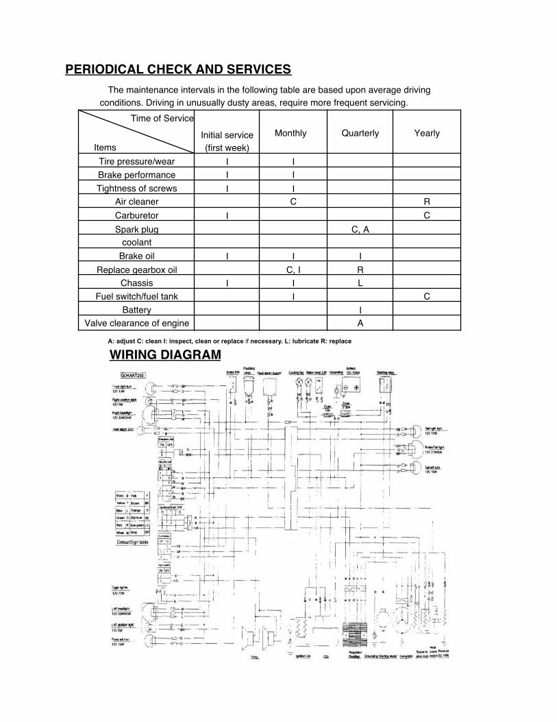
PERIODICAL CHECK AND SERVICESThe maintenance intervals in the following table are based upon average driving
conditions. Driving in unusually dusty areas, require more frequent servicing. Time of Service
ItemsInitial service (first week)
Monthly Quarterly Yearly
Tire pressure/wear I IBrake performance I ITightness of screws I I
Air cleaner C RCarburetor I CSpark plug C, A
coolantBrake oil I I I
Replace gearbox oil C, I RChassis I I L
Fuel switch/fuel tank I CBattery I
Valve clearance of engine A
A: adjust C: clean I: inspect, clean or replace if necessary. L: lubricate R: replace
WIRING DIAGRAM

WIRING DIAGRAM

Fig. 1
CYLINDER COMP.REF NO. PART NO. DESCRIPTION REQ’D NO.
1 172MM-023100 CYLINDER COMP 1
2 172MM-023002 CYLINDER SEAL 1
3 152MI-023300 TENSIONER 1
4 152MI-023003 SPRING SEAT FLANGE BOLT 15 152MI-023002 SPRING 1
6 152MI-023004 TENSIONER SEAL 17 172MM-023007 WATER INFLOW RUBBER TUBE 1
8 172MM-023009 WATER TUBE SHEATH 19 QC/T621-1999-B24 WIRE CLAMP 2
10 152MI-023009 WASHER 8.5 1
11 G B/T848-85-6-D SMALL WASHER 112 152MI-021005 DOWEL PIN 10 X 14 213 152MI-023008 FLANGE BOLT M6 X 18 214 152MI-080013 FLANGE BOLT M6 X 22 1
Parts Manual
CYLINDER COMP.

Fig. 2
CYLINDER COVER ASSY. (1)

PARTS MANUALCYLINDER COVER ASSY.(I)
REF NO. PART NO. DESCRIPTION REQ’D NO.
1 172MM-021009 OIL TUBE CLIP 1
2 172MM-021001 CYLINDER COVER 1
3 172MM-021006 PLATE 14 152MI-021011 CYLINDER COVER SEAL 1
5 172MM-021100 INLET ROCKER SHAFT 1
6 172MM-021200 EX ROCKER SHAFT 1
7 172MM-021400 OUTER OIL TUBE 18 152MI-021001 RUBBER RING 1
9 172MM-021431 OIL TUBE HOLDER 1
10 152MI-021003 SHOCK ABSORPTION RUBBER BAR 111 152MI-021004 BOLT M8 x 25 112 152MI-021015 BOLT M12 x 1.25 113 152MI-021013 BOLT M8 x 25 1
14 152MI-021008 VISION HOLE CAP 115 152MI-021016 WASHER 8 316 152MI-021012 EAR WASHER 117 152MI-021014 WASHER 12 218 152MI-021009 VISION HOLE CAP SEAL 119 152MI-021010 ROCKER SHAFT SEAL 220 GB/T818-2000 CROSS FLANGE BOLT 121 GB/T848-85-6 SMALL WASHER 222 152MI-021005 DOWEL PIN 10 x 14 223 152MI-021019 FLANGE BOLT M6 x 12 324 152MI-021017 FLANGE BOLT M6 x 25 125 152MI-013010 FALNGE BOLT M6 x 50 326 152MI-021018 FLANGE BOLT M6 x 55 127 172MM-021404 SHOCK ABSORPTION BUSH 1
28 172MM-021002 AIR TUBE JOINT 129 172MM-021300 AIR CLEANER HOLDER 1
30 172MM-021008 STOPPLE 1

Fig. 3CYLINDER COVER ASSY.(2)

PARTS MANUAL
CYLINDER COVER ASSY.(2)REF NO. PART NO. DESCRIPTION REQ’D NO.
1 172MM-022100 CYLINDER COVER ASSY. 12 172MM-022700 EX. TUBE FLANGE 13 152MI-022014 CAMSHAFT COVER 14 172MM-022008 EX. TUBE NUT 25 172MM-022010 CYLINDER COVER SEAL 16 172MM-022900 CARBURETOR RELAY SEAT 17 172MM-022500 INLET TUBE CLAMP 18 152MI-022810 TEMPERATURE RETAINER 19 152MI-022803 UPPER TEMPERATURE RETAINER COVER 1
10 152MI-022021 CARBURETOR COOLING RUBBER TUBE 111 172MM-022601 UNDERSIDE TEMPERATURE RETAINER COVER 1
12 172MM-022400 SPARK PLUG 113 152MI-021017 FLANGE BOLT M6 x 25 214 172MM-022800 EX. OUTLET SEAL 115 152MI-022600 WATER TEMPERATURE SENSOR 1
16 GB/T6191-1986 INNER HEX FLANGE BOLT M6 x 18 217 172MM-022007 EX. TUBE FLANGE BOLT 218 152MI-022012 WASHER 8 4
19 152MI-022013 ACORN NUT M8 420 152MI-022804 O-RING 14.8 x 1.9 121 172MM-022009 O-RING 31 x 2 122 152MI-022020 FLANGE BOLT M6 x 22 223 152MI-021005 DOWEL PIN 10 x 14 224 QC/T621-1999 WIRE CLIP 225 152MI-090005 FLANGE BOLT M6 x 16 2
26 152MI-023008 FLANGE BOLT M6 x 18 127 152MI-022017 CARBURETOR VENTILATION RUBBER TUBE 1
28 GB/T848-85 SMALL WASHER 129 152MI-022303 STOPPLE M12 x 1
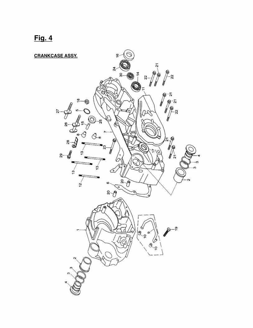
Fig. 4
CRANKCASE ASSY.

PARTS MANUAL
CRANKCASE ASSY.REF NO. PART NO. DESCRIPTION REQ’D NO.
1 172MM-011200 CRANKCASE, R. 12 152MI-011010 HANGER OUTER BUSH 23 152MI-011008 O-RING 15.8x2.4 44 152MI-011009 HANGER INNER BUSH 25 152MI-011013 O-RING 7.5 x 1.5 16 172MM-011003 CRANKCASE SEAL 17 172MM-011100 CRANKCASE, L. 18 172MM-011014 BRAKE SHOE SHOCK ABSORPTION WASHER 29 172MM-011400 INNER OIL TUBE 1
10 172MM-011002 INNER OIL TUBE SEAL 211 172MM-011300 INSULATION GASKET 112 172MM-011005 CYLINDER STUD BOLT B 113 172MM-011004 CYLINDER STUD BOLT A 314 NTN: TMB301 ROLL BEARING 115 172MM-011007 BRAKE SHOE BUSH, DOWEL PIN 116 172MM-011009 OIL SEAL 34 x 52 x 5 117 172MM-011001 OIL SEAL 28 x 40 x 8 118 152MI-011700 STOP NUT M8 119 152MI-021019 FLANGE BOLT M6 x 12 120 152MI-021005 DOWEL PIN 10 x 14 221 152MI-011017 FLANGE BOLT M6 x 60 522 152MI-011018 FLANGE BOLT M6 x 70 323 152MI-011016 FLANGE BOLT M6 x 125 124 NTN:6205LLU ROLL BEARING 125 172MM-011008 OIL SEAL 14 x 20 x 3.5 1
26 172MM-011010 BRAKE SHOE DOWEL PIN 127 172MM-011006 REAR SWING AXLE 1
28 172MM-011011 BRAKE CABLE PLATE 129 152MI-090005 FLANGE BOLT M6 x 16 130 NTN: HMK1416 NEEDLE BEARING 1

Fig. 5
Right Side Cover Assy

PARTS MANUAL
RIGHT SIDE COVER ASSY.REF NO. PART NO. DESCRIPTION REQ’D NO.
1 172MM-013013RUBBER HOSE (LINKED WITH CYLINDER
COVER) 1
2 172MM-013100RUBBER HOSE (LINKED WITH RIGHT SIDE
COVER) 13 172MM-013015 RUBBER HOSE (LINKED WITH AIR CLEANER) 14 172MM-013016 RUBBER HOSE CLIP 15 172MM-013002 RIGHT SIDE COVER 16 172MM-013008 PLATE 17 172MM-013012 RIGHT SIDE COVER SEAT 18 172MM-013007 OIL FILTER SCREEN LID 19 152MI-013100 FILTER CORE 1
10 172MM-013006 SPRING 111 172MM-013001 DIPSTICK 112 172MM-013019 EXHAUST THREE JOINT 113 152MI-021008 VISION HOLE CAP 114 172MM-013031 FLANGE BOLT M6 x 80 115 172MM-013028 O-RING 30 x 3.55 1
16 152MI-021009 VISION HOLE CAP SEAL 117 172MM-013030 O-RING 18 x 3.55 1
18 172MM-013005 OIL DISCHARGE BOLT M12 x 1.5 119 152MI-021014 WASHER 12 1
20 152MI-080008 DOWEL PIN 8 x 14 221 QC/T621-1999-A10 WIRE CLIP ROUND 222 QC/T621-1999-A12 WIRE CLIP ROUND 423 172MM-013010 VENTILATION JOINT 124 172MM-013009 WATER DISCHARGE JOINT 125 152MI-013009 FLANGE BOLT M6 x 40 3
26172MM-013026 RUBBER TUBE LINDED WITH AIR CLEANER
BUSH 127 152MI-071007 FLANGE BOLT M6 x 28 128 152MI-011018 FLANGE BOLT M6 x 70 3

PARTS MANUAL
CRANKSHAFT CON’ROD & PISTON ASSY.
REF NO. PART NO. DESCRIPTION REQ’D NO.
172MM-041000 CON’ROD ASSY. 1
1 172MM-040008 THE FIRST PISTON RING 1
172MM-040009 THE SECOND PISTON RING 1
2 172MM-042000 OIL RING ASSY. 1
3 172MM-040005 PISTON 1
4 172MM-040007 PISTON PIN 15 152MI-040011 OIL TUBE JOINT 1
6 152MI-040010 OIL TUBE JOINT SPRING 17 152MI-040006 WOODRUFF KEY 1
8 172MM-040006 PISTON PIN CIRCLIP 29 GB/T119-2000 COLUMN PIN 2 x 14 1
CRANKSHAFT CON'ROO & PISTON ASSY.Fig. 6

PARTS MANUAL
VALVE TRANNY ASSY.(1)REF NO. PART NO. DESCRIPTION REQ’D NO.
1 152MI-022500 VALVE TAPPET SEAL 22 172MM-022300 VALVE CAM 13 152MI-021007 ROCKER 24 172MM-022001 INLET VALVE 15 172MM-022005 EX. VALVE 16 172MM-022002 OUTER VALVE SPRING 27 172MM-022003 INNER VALVE SPRING 28 152MI-022005 SPRING VALVE DISC 29 152MI-022001 SPRING VALVE SEAT 2
10 152MI-022006 VALVE CLIP LOCK 411 NTN:16002 ROLL BEARING 212 GB894 1-86-15 BEARING CIRCLIP 113 172MM-022310 CHAIN WHEEL 114 172MM-022301 CAMSHAFT 1
Fig. 7VALVE TRANNY ASSY.(1)

PARTS MANUAL
VALVE TRANNY ASSY.(2)
REF NO. PART NO. DESCRIPTION REQ’D NO.1 172MM-022200 TIME CHAIN 12 172MM-023200 TENSIONER (LOWER) 13 172MM-023001 CHAIN GUIDE PLATE (UPPER) 14 GB96-85-6-D. Zn BIG WASHER 1
5 GB/T5781-2000 HEX FLANGE BOLT M6 x 12 1
Fig. 8VALVE TRANNY ASSY.(2)

PARTS MANUAL
LEFT SIDE COVER ASSY.REF NO. PART NO. DESCRIPTION REQ’D NO.
1 172MM-012001 LEFTSIDE COVER 12 172MM-012007 LEFT SIDE COVER SEAL 13 172MM-012004 PLATE 14 172MM-012003 FLANGE BOLT 25 152MI-012200 SHOCK ABSORPTION BLOCK ASSY. 26 152MI-011007 DOWEL PIN 010 x 16 2
7 172MM-012008 OIL DISCHARGE BOLT VISION HOLE CAP 1
8GBT818-2000-
M5X8 CROSS FLANGE BOLT 4
9 172MM-012100 WIRE CLAMP 110 152MI-090005 FLANGE BOLT M6 x 16 111 172MM-012002 DUST-PROOF BAR 1 112 172MM-012006 DUST-PROOF BAR 2 113 172MM-012005 WOOL MAT 1
Fig. 9LEFT SIDE COVER ASSY.

PARTS MANUAL
WATER PUMP ASSY.REF NO. PART NO. DESCRIPTION REQ’D NO.
1 172MM-080004 WATER PUMP IMPELLER 12 152MI-081000 WATER SEAL 13 172MM-080003 WATER PUMP HOUSING 14 172MM-080002 WATER PUMP HOUSING SEAL 15 172MM-080001 WATER PUMP SHAFT 16 152MI-013009 FLANGE BOLT M6 x 40 27 152MI-02017 FLANGE BOLT M6 x 25 2
8 GBT893 1-86-19 CIRCLIP 19 152MI-080007 WASHER 7.5 x 13 x 1.2 1
10 152MI-080011 WASHER 6 x 12 x 1 111 NTN:6800 ROLL BEARING 212 172MM-08005 OIL SEAL 10x20x5 113 152MI-080008 DOWEL PIN 8x14 2
Fig. 10 WATER PUMP ASSY.

PARTS MANUAL
CARBURETOR COMP.REF NO. PART NO. DESCRIPTION REQ’D NO.
1 172MM-100000 CARBURETOR COMP 1
Fig. 11CARBURETOR COMP.

PARTS MANUAL
OIL PUMP ASSY.REF NO. PART NO. DESCRIPTION REQ’D NO.
1 152MI-071000 OIL PUMP ASSY. 12 152MI-071002 OIL PUMP 13 152MI-071003 OIL PUMP COVER PLATE 14 152MI-071001 OIL PUMP SHAFT 15 152MI-070001 OIL PUMP SPROCKET 16 152MI-073000 OIL PUMP CHAIN 17 152MI-071004 INNER OIL PUMP ROTOR 18 152MI-071005 OUTER OIL PUMP ROTOR 19 152MI-070002 OIL PUMP DIVISION PLATE A 1
10 152MI-072000 OIL PUMP DIVISION PLATE B 111 GB878-85 FLANGE BOLT M3 x 12 112 152MI-0710006 DOWEL PIN 4x6.5 113 GB897 1-86-10 CIRCLIP 114 152MI-021019 FLANGE BOLT M6 x 12 115 152MI-071007 FLANGE BOLT M6 x 28 2
Fig. 12OIL PUMP ASSY.

PARTS MANUAL
CLUTCH ASSY.REF NO. PART NO. DESCRIPTION REQ’D NO.
1 172MM-052500 OUTER WHEEL CLUTCH 12 172MM-052400 DRIVEN DISC 13 172MM-052003 SIDE DISC 14 172MM-052006 CLUTCH RETURN SPRING 35 172MM-052600 CENTRIFUGAL BLOCK 3
6 GB/T8931-86-28 CIRCLIP 17 172MM-052700 DRIVE BELT 18 172MM-052300 DRIVEN WHEEL 19 172MM-052100 MOVABLE DRIVEN WHEEL 1
10 172MM-052002 GUIDE COLUMN PIN 411 172MM-052001 GUIDE ROLLER 412 172MM-052004 CLUTCH SPRING 113 172MM-052200 SEAL BUSH 114 172MM-052005 FLAT NUT M30 x 1 115 GB/T896-86-6 CIRCLIP 3
16 GB278-89-1060902 ROLL BEARING 117 172MM-052310 NEEDLE BEARING 22 x 29 x 18 118 172MM-052008 NUT M12x 1.25 119 172MM-052104 DRIVEN WHEEL OIL SEAL 220 GB3452.1-82 O-RING 46.2 x 1.8 2
Fig. 13CLUTCH ASSY.

PARTS MANUAL
ELECTRIC STARTER ASSY.
REF NO. PART NO. DESCRIPTION REQ’D NO.
1 172MM-090001 DOUBLE GEAR 1
2 172MM-092000 DRIVEN GEAR 13 172MM-091000 DOUBLE-GEAR 1
4 172MM-090007 FIX PLATE 1
5 172MM-093000 START MOTOR 1
6 152MI-080013 FLANGE BOLT M6’22 27 172MM-090008 FLANGE BOLT M6*14 1
Fig.14ELECTRIC STARTER ASSY.

PARTS MANUAL
REDUCTION BOX ASSY.REF NO. PART NO. DESCRIPTION REQ’D NO.
1 172MM-062000 VENTILATION PIPE 12 172MM-060009 REDUCTION BOX CAP 13 172MM-061000 REDUCTION CASE CAP SEAL 14 172MM-060001 CHIEF SHAFT 15 172MM-060003 SECONDARY SHAFT 16 172MM-060006 SECONDARY GEAR SHAFT 17 172MM-060007 OUTPUT SHAFT 18 172MM-060008 OUTPUT GEAR 19 172MM-060010 FLANGE BOLT M8 x 38 3
10 172MM-060011 FLANGE BOLT M8 x 28 211 152MI-06Q003 STOP GASKET 14 112 172MM-060004 STOP GASKET 14 113 152MI-060009 WASHER 6 114 152MI-060010 WASHER 10 115 NTN: 6304 ROLL BEARING 116 172 MM-060002 ROLL BEARING 22 x 50 x 14 117 GB9877.1 -88 OIL SEAL 22 x 35 x 5 118 152MI-021005 DOWEL PIN 10 x 14 219 GB/T894.1-86-24 CIRCLIP 1
20 152MI-060011 FLANGE BOLT M10 X 1.25 OIL DISCFIARGE 1
21 152MI-080012 FLANGE BOLT M6 x 32 222 NTN: HMK1416 NEEDLE BEARING 1
Fig. 15REDUCTION BOX ASSY.

PARTS MANUAL
GEARBOX ASSY.
GEARBOX ASSY.REF NO. PART NO. DESCRIPTION REQ’D NO.
1 172MM-051004 SLIDE BLOCK 32 172MM-051005 DRIVE WHEEL 13 172MM-051003 DRIVE WHEEL BUSH 14 172MM-051100 MOVABLE DRIVE WHEEL 15 172MM-051200 CENTRIFUGAL ROLLER 66 172MM-051001 DRIVE WHEEL CAP 17 172MM-051002 SLOPE PLATE 18 GB3452 1-82 O-RING 19 GB9074 14-88 FLANGE BOLT 3
10 172MM-051007 NUT M14 x 1.5 111 172MM-051006 WASHER 14.5x30x2 112 152MI-051103 OIL SEAL 27x34 x3.5 2
Fig. 16

PARTS MANUAL
MAGNETO COMP.
MAGNETO COMP.REF NO. PART NO. DESCRIPTION REQ’D NO.
1 172MM-094000 CLUTCH 12 172MM-033000 IGNITION COIL 13 172MM-013008 WIRE PLATE 14 172MM-031000 FLYWHEEL 15 172MM-032000 STATOR 16 GB/T70 1-2000 INNER HEX FLANGE BOLT M8 X 18 37 172MM-040001 NUT M16x 1 18 172MM-040002 WASHER 16.3x30x2 19 152MI-030002 FLANGE BOLT M5 x 16 2
10 152MI-060012 FLANGE BOLT M6 x 30 3
Fig. 17

Fig. 18FRAME GROUP
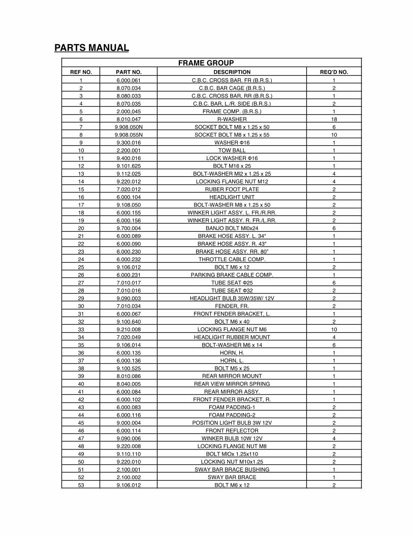
PARTS MANUALFRAME GROUP
REF NO. PART NO. DESCRIPTION REQ’D NO.1 6.000.061 C.B.C. CROSS BAR. FR (B.R.S.) 12 8.070.034 C.B.C. BAR CAGE (B.R.S.) 23 8.080.033 C.B.C. CROSS BAR, RR (B.R.S.) 14 8.070.035 C.B.C. BAR, L./R. SIDE (B.R.S.) 25 2.000,045 FRAME COMP. (B.R.S.) 16 8.010.047 R-WASHER 187 9.908.050N SOCKET BOLT M8 x 1.25 x 50 68 9.908.055N SOCKET BOLT M8 x 1.25 x 55 109 9.300.016 WASHER Φ16 1
10 2.200.001 TOW BALL 111 9.400.016 LOCK WASHER Φ16 112 9.101.625 BOLT M16 x 25 113 9.112.025 BOLT-WASHER Ml2 x 1.25 x 25 414 9.220.012 LOCKING FLANGE NUT M12 415 7.020.012 RUBER FOOT PLATE 216 6.000.104 HEADLIGHT UNIT 217 9.108.050 BOLT-WASHER M8 x 1.25 x 50 218 6.000.155 WINKER LIGHT ASSY. L. FR./R.RR. 219 6.000.156 WINKER LIGHT ASSY. R. FR./L.RR. 220 9.700.004 BANJO BOLT Ml0x24 621 6.000.089 BRAKE HOSE ASSY. L. 34" 122 6.000.090 BRAKE HOSE ASSY. R. 43" 123 6.000.230 BRAKE HOSE ASSY. RR. 80” 124 6.000.232 THROTTLE CABLE COMP. 125 9.106.012 BOLT M6 x 12 226 6.000.231 PARKING BRAKE CABLE COMP. 127 7.010.017 TUBE SEAT Φ25 628 7.010.016 TUBE SEAT Φ32 229 9.090.003 HEADLIGHT BULB 35W/35W/ 12V 230 7.010.034 FENDER, FR. 231 6.000.067 FRONT FENDER BRACKET, L. 132 9.100.640 BOLT M6 x 40 233 9.210.008 LOCKING FLANGE NUT M6 1034 7.020.049 HEADLIGHT RUBBER MOUNT 435 9.106.014 BOLT-WASHER M6 x 14 636 6.000.135 HORN, H. 137 6.000.136 HORN, L. 138 9.100.525 BOLT M5 x 25 139 8.010.086 REAR MIRROR MOUNT 140 8.040.005 REAR VIEW MIRROR SPRING 141 6.000.084 REAR MIRROR ASSY. 142 6.000.102 FRONT FENDER BRACKET, R. 143 6.000.083 FOAM PADDING-1 244 6.000.116 FOAM PADDING-2 245 9.000.004 POSITION LIGHT BULB 3W 12V 246 6.000.114 FRONT REFLECTOR 247 9.090.006 WINKER BULB 10W 12V 448 9.220.008 LOCKING FLANGE NUT M8 249 9.110.110 BOLT MlOx 1.25x110 250 9.220.010 LOCKING NUT M10x1.25 251 2.100.001 SWAY BAR BRACE BUSHING 152 2.100.002 SWAY BAR BRACE 153 9.106.012 BOLT M6 x 12 2

Fig. 19STEERING SHAFT ASSY.

PARTS MANUAL STEERING SHAFT ASSY.
REF NO. PART NO. DESCRIPTION REQ’D NO.1 7.010.041 STEERING BOLT COVER 12 9.100.612 BOLT STRAP M6x12 33 8.030.024 SPINDLE BRACKET 14 7.020.038 STEERING WHEEL 15 6.000.122 STEERING SHAFT 16 7.010.026 STEERING SHAFT BUSH 27 9.700.020 SPECIAL WASHER Φ20 18 9.700.120 CIRCLIP Φ20 19 9.100.825 BOLT M8 x 25 2
10 9.400.008 LOCK WASHER Φ8 211 6.000.093 STEERING KNUCKLE 112 4.000.014 STEERING GEAR 113 9.108.025 BOLT-WASHER M8 x 1.25 x 25 414 9.900.016 ROUND NUT M16 x 1.5 215 4.000.008 STEERING BALL JOINT 216 9.200.010 NUT M10 217 7.020.002 BALL JOINT DUST COVER 218 8.010.157 TIE ROD 219 6.000.062 ROD END 220 9.300.010 FLAT WASHER Φ10 221 9.400.010 LOCK WASHER Φ10 222 9.800.010 CASTLE NUT M10 223 9.500.215 COTTER PIN Φ2x15 224 7.020.066 STEERING KNUCKLE DUST COVER 225 8.020.014 STEERING GEAR BRACKET 226 9.220.008 LOCKING FLANGE NUT M8 827 9.708.145 THROTTLE PEDAL BOLT M8 x 1.25 x 145 128 8.040.001 THROTTLE PEDAL RETURN SPRING, L. 129 9.108.040 BOLT-WASHER M8 x 1.25 x 40 230 9.200.008 NUT M8 231 4.000.016 THROTTLE PEDAL COMP. 132 9.600.515 PAN SCREW M5 x 15 233 9.300.005 FLAT WASHER Φ6 234 9.210.005 NYLON LOCK NUT M5 235 4.000.015 BRAKE PEDAL COMP. 136 9.700.624 PIN Φ6 x 24 137 8.010.081 SPINDLE PIN 238 9.500.212 COTTER PIN Φ2x12 139 6.000.063 BRAKE LAMP SWITCH ASSY. 140 9.600.306 PAN SCREW M3 x 6 241 7.010.004 PEDAL BUSH 442 8.040.007 BRAKE PEDAL RETURN SPRING, R. 143 9.708.222 BRAKE PEDAL BOLT M8 x 1.25 x 222 144 6.000.076 MASTER CYLINDER 145 9.108.035 BOLT-WASHER M8 x 1.25 x 35 246 7.020.036 THROTTLE PEDAL PAD 147 7.020.037 BRAKE PEDAL PAD 148 6.000.134 STEERING WHEEL LOCK 149 8.070.044 MASTER CYLINDER BRACKET 1

Fig. 20FRONT SUSPENSION ARM ASSY.

PARTS MANUAL
FRONT SUSPENSION ARM ASSY.REF NO. PART NO. DESCRIPTION REQ’D NO.
1 2.000.028 STRUT AND SPINDLE SUPPORT, R. 12 9.108.105 BOLT-WASHER M8 x 1.25 x 105 23 8.010.015 UPPER SUSPENSION ARM COLLAR 24 7.010.003 UPPER SUSPENSION ARM BUSH 45 4.000.004 UPPER SUSPENSION ARM 26 9.220.008 LOCKING FLANGE NUT M8 27 9.800.012 CASTLE NUT M12 28 7.020.025 BALL HEAD DUST SEAL 49 8.020.053 BALL HEAD SPACER 4
10 2.000.027 STRUT AND SPINDLE SUPPORT, L. 111 9.908.104 BOLT STRAP M8 x 14 4
12 8.010.014 LOWER SUSPENSION ARM COLLAR 413 9.906.012 BOLT STRAP M6 x 12 1214 6.000.141 FR. WHEEL ASSY., R. 20 x 7-8 115 7.020.016 FR. BRAKE CALIPER PAD SET 216 6.000.028 FRONT BRAKE CALIPER, L. 117 8.010.054 BRAKE DISC. 218 9.040.002 DUST SEAL 47x25-7 219 9.030.002-Z BEARING 6204-Z 220 9.710.031 TIRE BOLT M10x1.25x31 821 8.010.085 WHEEL HUB 222 9.030.010-Z BEARING 6202-Z 223 8.010.118 CAP LUG NUT M10 824 7.020.050 TIRE, FR. 20 x 7-8 225 6.000.142 RIM.FR. 226 9.220.010 LOCKING FLANGE NUT M10 827 9.800.014 CASTLE NUT Ml4 228 9.500.220 COTTER PIN Φ2 x 20 229 7.020.039 HUB COVER 230 9.110.040 BOLT-WASHER M10 x 1.25 x 40 431 6.000.095 FRONT BRAKE CALIPER, R. 132 6.000.325 CUSHION ASSY., FR. L=325 233 9.110.080 BOLT-WASHER M10 x 1.25 x 80 434 8.020.034 LOWER SUSPENSION ARM DUST CAP 835 7.010.002 LOWER SUSPENSION ARM BUSH 836 9.040.001 O-RING Φ21.2x2.65 837 4.000.023 LOWER SUSPENSION ARM ASSY. 238 6.000.140 FR. WHEEL ASSY., L. 20 x 7-8 139 8.010.140 ACORN NUT M12 240 9.500.200 COTTER PIN Φ3.2 x 26 2

Fig.21FULL SHIFTING ASSY.

PARTS MANUAL
FULL SHIFTING ASSY.
REF NO. PART NO. DESCRIPTION REQ’D NO.1 9.110.020 BOLT-WASHER M10x20 22 9.110.100 BOLT-WASHER M10 x 100 33 6.000.240 GEAR BOX SUSPENSION ARM 14 8.010.168 COLLAR #1 15 9.112.230 BOLT-WASHER M12x1.25x230 16 6.000.239 PIVOT ARM SHIFT C 17 7.020.068 CUSHION BUSH 48 9.220.012 LOCKING FLANGE NUT M12 29 8.010.167 COLLAR #2 1
10 9.112.190 BOLT-WASHER M12 x 1.25 x 190 111 6.000.238 PIVOT ARM SHIFT B 112 9.110.200 BOLT-WASHER M10 x 1.25 x 200 113 9.220.010 LOOKING FLANGE NUT M10 514 6.000.237 PIVOT ARM SHIFT A 115 7.010.004 PEDAL BUSH 216 9.108.145 BOLT M8x1.25x145 117 6.000.235 RIGHT TURN CLEVIS ROD HEAD 118 9.110.030 BOLT-WASHER M10x30 219 9.200.010 RIGHT TURN NUT M10 120 6.000.236 SHORT CLEVIS ROD 121 9.200.010-L LEFT TURN NUT M10 122 6.000.234 LEFT TURN CLEVIS ROD HEAD 123 9.110.040 BOLT-WASHER M10x40 124 6.000.233 LONG CLEVIS ROD 125 9.700.513 PIN Φ5x13.5 126 9.500.212 COTTER PIN 127 4.000.031 SHIFTER HOUSE ASSY. 128 9.100.612 BOLT M6 x 12 429 6.000.258 PARKING BRAKE ASSY. 130 9.108.020 BOLT-WASHER M8 x 20 231 9.300.008 WASHER Φ8 2

REAR CARGO RACK / SEAT / BELT Fig. 22
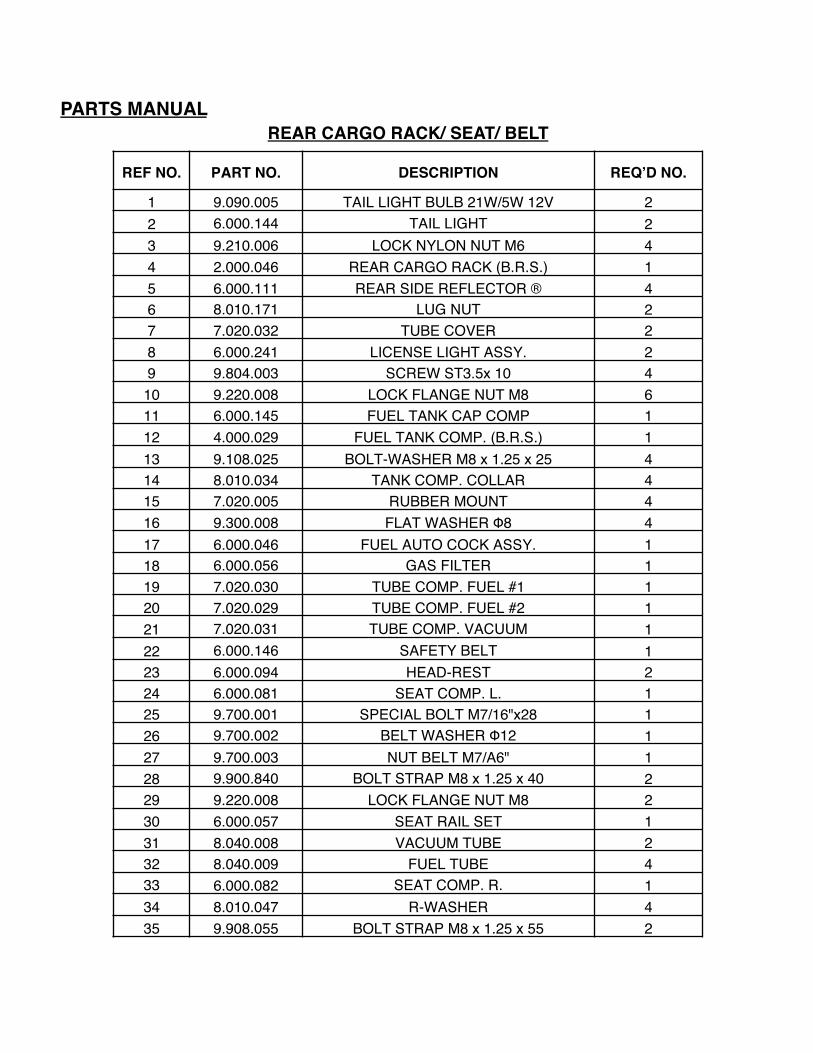
PARTS MANUALREAR CARGO RACK/ SEAT/ BELT
REF NO. PART NO. DESCRIPTION REQ’D NO.
1 9.090.005 TAIL LIGHT BULB 21W/5W 12V 22 6.000.144 TAIL LIGHT 23 9.210.006 LOCK NYLON NUT M6 44 2.000.046 REAR CARGO RACK (B.R.S.) 15 6.000.111 REAR SIDE REFLECTOR ® 46 8.010.171 LUG NUT 27 7.020.032 TUBE COVER 28 6.000.241 LICENSE LIGHT ASSY. 29 9.804.003 SCREW ST3.5x 10 4
10 9.220.008 LOCK FLANGE NUT M8 611 6.000.145 FUEL TANK CAP COMP 112 4.000.029 FUEL TANK COMP. (B.R.S.) 113 9.108.025 BOLT-WASHER M8 x 1.25 x 25 414 8.010.034 TANK COMP. COLLAR 415 7.020.005 RUBBER MOUNT 416 9.300.008 FLAT WASHER Φ8 417 6.000.046 FUEL AUTO COCK ASSY. 118 6.000.056 GAS FILTER 119 7.020.030 TUBE COMP. FUEL #1 120 7.020.029 TUBE COMP. FUEL #2 121 7.020.031 TUBE COMP. VACUUM 122 6.000.146 SAFETY BELT 123 6.000.094 HEAD-REST 224 6.000.081 SEAT COMP. L. 125 9.700.001 SPECIAL BOLT M7/16"x28 126 9.700.002 BELT WASHER Φ12 127 9.700.003 NUT BELT M7/A6" 128 9.900.840 BOLT STRAP M8 x 1.25 x 40 229 9.220.008 LOCK FLANGE NUT M8 230 6.000.057 SEAT RAIL SET 131 8.040.008 VACUUM TUBE 232 8.040.009 FUEL TUBE 433 6.000.082 SEAT COMP. R. 134 8.010.047 R-WASHER 435 9.908.055 BOLT STRAP M8 x 1.25 x 55 2

FIG.23 AIR CLEANER/ RADIATOR/ BATTERY/ MUFFLER ASSY.

PARTS MANUAL
AIR CLEANER/ RADIATOR/ BATTERY/ MUFFLER ASSY.
REF NO. PART NO. DESCRIPTION REQ’D NO.
1 7.090.035 AIR CLEANER DUCT 12 7.090.036 AIR CLEANER CLAMP 23 7.090.037 AIR CLEANER CASE COMP. 14 7.090.038 AIR CLEANER ELEMENT 15 7.090.039 AIR CLEANER COVER 16 9.805.003 TAPPING SCREW M5 x 16 77 7.090.040 AIR CLEANER GAUZE COVER 18 7.090.041 AIR CLEANER ELEMENT GAUZE 19 4.000.032 AIR CLEANER ASSY. 1
10 7.090.042 TUBE COMP. WATER 1# 111 7.090.043 TUBE COMP. WATER 2# 1
12 7.090.044 TUBE CLAMP 4 13 7.090.045 TUBE COMP. WATER 3# 1
14 7.090.046 TUBE COMP. WATER 4# 115 9.100.830 BOLT M8x 30x1.25 216 7.090.047 RADIATOR COMP. COLLAR 217 7.020.069 RUBBER MOUNT 218 9.200.008 NUT M8 219 6.000.248 COLLANT TANK 120 7.010.028 BATTERY COVER 121 6.000.085 BATTERY (YTX12-BS) 122 7.021.023 BATTERY BAND 123 7.020.020 BATTERY LOWER 124 7.090.049 MUFFLER COMP. EX. 125 9.040.027 MUFFLER JOINT NUT M6 226 7.090.050 EX. PIPE GASKET 127 9.110.030 BOLT-WASHER M10 x 1.25 x 30 128 9.020.010 NUT M10 129 4.000.033 RADIATOR COMP 130 7.090.051 TUBE CLAMP 231 9.200.006 NUT M6 232 6.000.249 FAN COMP. 133 7.090.052 BOLT 634 2.000.047 250CC ENGINE 1

FIG.24
GEAR BOX ASSY.

PARTS MANUAL
GEAR BOX ASSY.REF NO. PART NO. DESCRIPTION REQ’D NO.
1 9.040.012 DUST SEAL Φ56x35x 10 22 9.030.011 BEARING RADIAL BALL E6007 23 7.090.001 WAHSER Φ45x35x2 24 7.090.002 KEY STOCK 25 7.090.003 FINAL SHAFT 16 7.090.004 FINAL GEAR 17 9.030.002 BEARINGN RADIAL BALL E6204 28 7.090.005 WAHSER Φ35 x 20.5 x2 29 7.090.006 COUNTER GEAR A 1
10 7.090.007 COLLER 111 7.090.008 COUNTER SHAFT 112 7.090.009 COUNTER GEAR B 113 9.030.005 BEARING RADIAL BALL E6005 114 7.090.010 WASHER Φ35 x 20 x 5.5 115 7.090.011 IN PUT GEAR A 116 7.090.012 INTERNAL GEAR 117 7.090.013 SLIDER COLLAR 118 7.090.014 PIVOT ARM SLIDER 119 7.090.015 IN PUT GEAR B 120 7.090.016 WASHER Φ35x25x4 121 7.090.017 BEARING RADIAL BALL E6204 122 9.040.013 DUST SEAL Φ42 x 25 x 8 123 7.090.018 LOCKING PIN IN/OUT Φ4x8 124 7.090.019 PIVOT GEAR SHIFT 125 8.030.041 L-SIDE CASE COVER 126 7.090.020 SWING ARM CUSHION BUSH 627 9.106.040 BOLT-WAHSER M6x40 1428 7.090.021 PIVOT SHAFT PIN 129 9.500.408 COTTER PIN Φ4x8 130 7.090.022 PIVOT ARM SHAFT 131 7.090.023 GEAR CASE COVER GASKET 132 9.108.020 BOLT-WASHER M8 x 20 433 7.090.024 OUTER SHIFT BRACKET 134 9.100.610 BOLT M6 x 10 435 7.090.025 GASKET PLANE 136 7.090.026 GASKET 137 7.090.027 AIR TUBE 138 7.090.028 TUBE CUP 139 7.090.029 AIR VENT 140 7.090.030 COLLAR A 241 7.090.031 DOWEL PIN Φ8x20 242 9.101.025 BOLT M10 x 25 143 7.090.032 SPRING 144 7.090.033 STEEL BALL 145 7.090.035 COLLAR B 146 8.030.040 GEAR CASE 147 9.700.008 WASHER Φ8 148 9.100.812 BOLT M8 x 12 149 9.040.014 DUST SEAL Φ22x10x7 1

FIG.25REAR SUSPENSION ASSY.

PARTS MANUAL
REAR SUSPENSION ASSY
REF NO. PART NO. DESCRIPTION REQ’D NO.
1 7.020.039 RR. HUB COVER 22 9.500.430 COTTER PIN $4 x 30 23 9.800.018 CASTLE NUT M18 24 8.010.118 LUG NUT CAP M10 85 6.000.143 RIM. RR. 26 8.010.169 REAR WHEEL HUB 27 9.710.031 TIRE BOLT Ml Ox 1.25x31 88 9.030.007 BEARING 6007 49 8.010.170 COLLAR 2
10 9.112.055 BOLT-WASHER Ml2 x 1.25 x 55 211 9.220.012 LOCKING FLANGE NUT M12 x 1.25x50 412 9.112.050 BOLT-WASHER Ml2 x 1.25 x 50 213 7.020.008 SWING ARM CUSHION BUSH 414 6.000.242 BALANCE LEVER LINK ROD 215 9.220.010 LOCKING FLANGE NUT M10 x 1.25 216 6.000.243 BALANCE LEVER 117 9.108.020 BOLT-WASHER M8 x 20 x 1.25 418 8.010.053 RR. BRAKE DISC. 119 8.030.036 BRAKE DISC. BASE 120 9.101.018 BOLT MlOx 1.5x18 121 7.020.022 RR. BRAKE PAD SET 122 6.000.229 CALIPER HYDRAULICAL BRAKE, RR. 123 9.908.014 ALLEN HEAD BOLT M8 x 1.25 x 16 224 6.000.244 CV/ SHAFT JOINT 225 6.000.245 CUSHION ASSY.. RR. L=480 226 6.000.247 SWING ARM COMP. R. 127 6.000.246 SWING ARM COMP. L. 128 9.040.011 DUST SEAL 062 x 44 x 10 229 6.000.148 REAR WHEEL ASSY., R. 130 6.000.147 REAR WHEEL ASSY., L. 131 7.020.052 TIRE, RR. 22x10-10 132 9.906.016 BOLT-WASHER M6 x 16 633 7.010.059 FENDER, RR. 234 6.000.068 REAR FENDER BRACKET, R. 135 6.000.101 REAR FENDER BRACKET, L. 136 9.108.045 BOLT-WASHER M8 x 1.25 x 45 2

WIRE HARNESS / ELECTRICAL

PARTS MANUAL
WIRE HARNESS / ELECTRICAL
REF NO. PART NO. DESCRIPTION REQ’D NO.
1 9.100.630 BOLT M6 x 30 22 9.200.006 NUT M6 23 6.000.250 REGULATE RECTIFIER COMP. 14 9.600.615 PAN SCREW M6 x 15 45 9.300.006 WASHER Φ6 46 9.210.005 LOCKING NYLON NUT M6 27 7.010.038 SWITCH PANEL COVER 18 7.010.061 BOLT COVER 49 6.000.079 HORN SWITCH 1
10 7.020.051 POWER OUTLET COVER 111 6.000.087 POWER OUTLET 112 6.000.113 WINKER SWITCH UNIT 113 6.000.160 DIMMER SWITCH UNIT 114 6.000.159 ENGINE STOP BUTTON 115 6.000.158 IGNITION START SWITCH 116 6.000.153 RELAY COMP. AUDIBLE PILOT & WINKER 117 6.000.251 TEMPERATURE BUZZER 118 6.000.252 HORN RECTIFIER 119 6.000.253 SOCKET COMP. 120 9.600.655 PAN SCREW M6 x 55 221 6.000.254 WIRE HARNESS 222 7.010.029 ELECTRIC ASSY. COVER 123 6.000.255 C-D.l. UNIT COMP. 124 6.000.256 STARTING RELAY 125 6.000.257 iGNITION COIL COMP. 126 9.210.006 LOCK NYLON NUT M5 127 9.600.525 PAN SCREW M5 x 25 128 6.000.038 RESISTOR COMP. 10W 10 129 9.600.410 PAN SCREW M4 x 10 130 9.210.004 LOCK NYLON NUT M4 1

WARNING STICKERS Fig. 27
WARNING STICKERSREF NO. PART NO. DESCRIPTION REQ’D NO.
1 9.090.007 LABEL. PARKING BRAKE 12 9.090.008 LABEL. REVERSE LEVER 13 9.090.023 LABEL.GEAR CASE 14 9.090.010 LABEL. NO LONG HAIR 15 9.090.011 LABEL. WARNING 16 9.090.012 LABEL. NO CLIMBING 17 9.090.013 LABEL. WARNING 18 9.090.014 LABEL. SEAT BELT 19 9.090.024 LAB EL. RADIATOR 1
10 9.090.016 LABEL. TWISTER 311 9.090.017 LABEL. WARNING 112 9.090.025 LABEL. HAMMERHEAD 250 113 9.090.026 LABEL.HAMMERHEAD 250 R.SIDE 114 9.090.027 LABEL.HAMMERHEAD 250 L.SIDE 1