owners instruction manual
TRANSCRIPT
ColdZone
OWNERS
INSTRUCTION MANUAL
221 South Berry Street P.O. Box 1030 Brea, CA 92621-4888 Brea, CA 92622-1030
Phone: 714/529-4461 * Fax: 714/529-8503
TABLE OF CONTENTS TYPICAL FLUID COOLER SYSTEM………………………………...1 INTRODUCTION………………………………………………………..2
General Description …...........................................................................2 Closed-Loop Glycol Fluid Cooler..……………………………………2 Closed-Coupled Centrifugal Pump …………………………………..2 Heat Exchanger ………………….…………………………………….2 Fan Motor .,……………………….……………………………………3 Glycol Fluid ……………………………………………………………3 Fluid Manifolds ………………………………………………………..3 Control Panel ………………………………………………………….3 Electrical Characteristics ……………………………………………..3 Standard Components ………………………………………………...3 Diagram Size and Weight………………..…………………………....4 Diagram Rigging Detail ……………………………………………….5
INSTALLATION………………………………………………………...6 Receipt and Inspection of Equipment…………….………………….6 Lifting Instructions …………………………………...………………6 Location and Ventilation ……………………………..………………6 Installation Area ………………………………………...…………….6 Roof Rail Requirements …………………………………..…………..6 Pitch Pocket ……………………………………………………………6 Electrical ……………………………………………………..………...7 Glycol Piping …………………………………………………………..7 Diagram Rail, and Cubb Detail ………………………………………8 Diagram Wiring Diagram …………………………………….………9
START-UP PROCEDURE …….………………………………………10 Mechanical Seal……………………………………………………….10
MAINTENANCE …………………………………….…………………11 Heat Transfer Surface ………………………………………………..11 Electric Motor ………………………………………………………...11 Repairs or Replacement of Parts ………………………………….....11 Removal of Old Seal …………………………………………………. 11 Installation of Replacement Seal ……………………………………..12
SERVICE DIAGNOSIS………………………………………………… 13 Trouble Shooting Chart ………………………………………………13
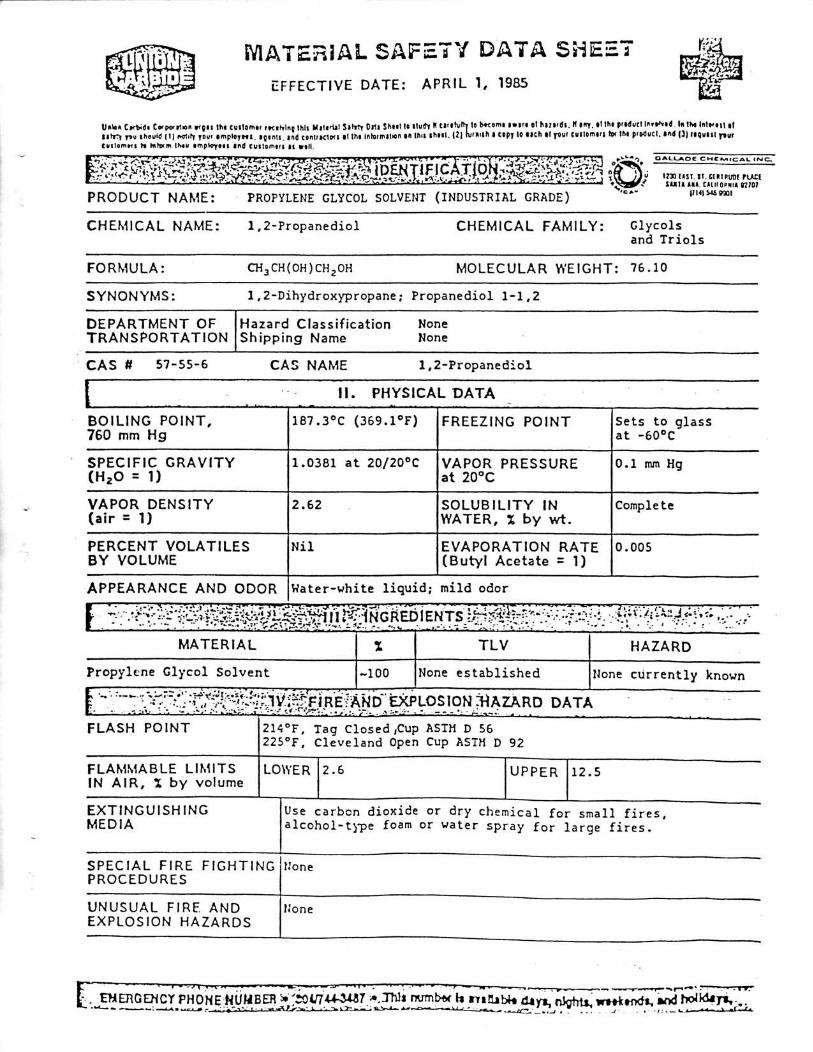
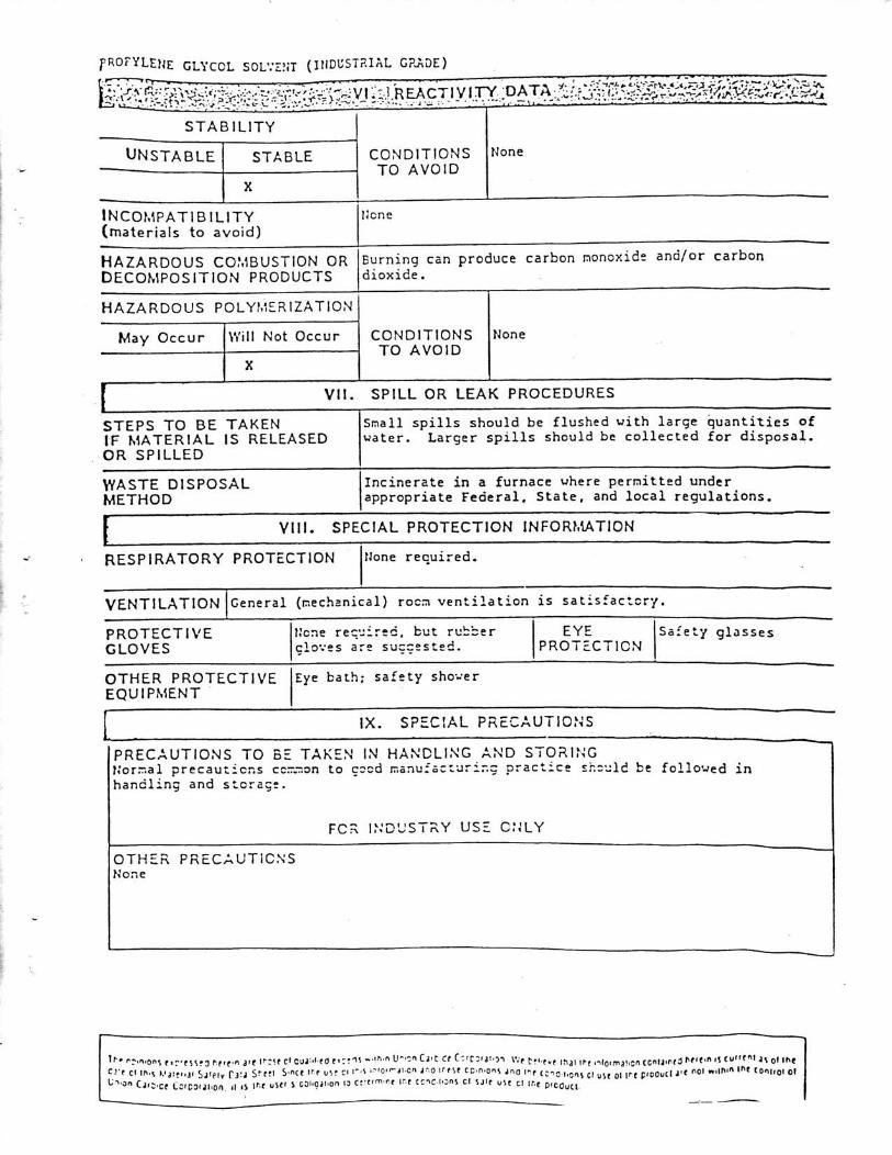
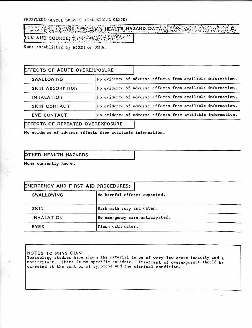
STANDARD WARRANTY ……………………………………………..14 PROPYLENE GLYCOL (MSDS)…………………………………...15-17
INTRODUCTION
GENERAL DESCRIPTION
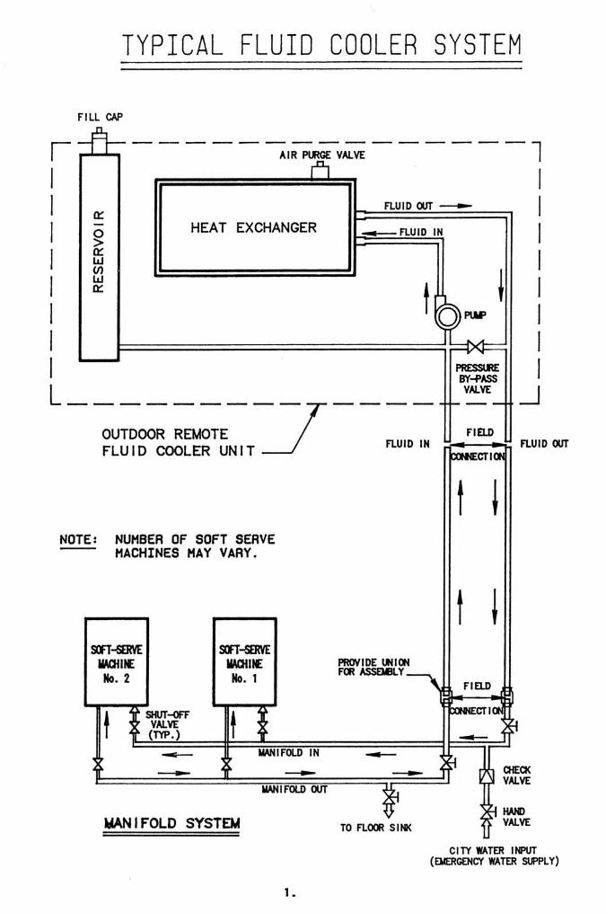
The COLDZONE "Fluid Cooler" system is (U.L. File #SA2285, Vol. 1 Section 3) designed primarily for fast food requirements and installations where only a small quantity of water cooled refrigerated fixtures are to be remote, ie; soft-serve freezers for ice cream and frozen yogurt and water cooled condensing units. This will allow heat dissipation on the roof for the high heat producing condensing units, thus eliminating water consumption and reducing indoor air conditioning requirements at a very nominal cost. Totally pre-piped, pre-wired, and weatherized for fast, low cost rigging and installation on rooftop, it is only necessary to provide main power lines to control panel. In addition, the unit has been carefully designed for easy installation, providing ready access for service and maintenance of all major components.
CLOSED-LOOP GLYCOL FLUID COOLER
A closed-loop glycol fluid cooling system is installed with the anticipation that it will provide many years of trouble-free operation with minimum maintenance. Usually the length of service life realized from a particular fluid cooler is directly proportional to the care with which the original installation was performed. Cleanliness is absolutely mandatory when installing the system. All tubing, valves and fittings must be carefully inspected to insure cleanliness. The correct electrical supply must be provided to the fluid cooler control panel. The voltage at the pump and fan motor terminals should be checked during start-up and unit operation under full load to insure a tolerance of plus or minus 10% of the nameplate rating.
CLOSED-COUPLED CENTRIFUGAL PUMP
A closed-coupled centrifugal pump is precision built for liquid transfer and recirculation of glycol fluid from water copied condenser to rooftop heat exchanger. The pump is equipped with a drip-proof motor with shielded ball bearings, thermal protector, sintered iron and BUNA N mechanical seal and type 303 stainless steel shaft. Discharge port of the pump can be rotated in 90° increments to accommodate various applications.
HEAT EXCHANGER
A heat exchanger is installed in the fluid cooler system to reject heat on the roof to provide a 10°F differential. Each coil is made with aluminum fins bonded upon copper tubing. A shroud is incorporated in the construction of the condenser to provide controlled air flow over the cooling surface.
2.
FAN MOTOR Each fluid cooler package is equipped with at least one fan motor to reject heat. Fan motors capable of operating for years with trouble free maintenance are permanently lubricated with inherent overload protection to prevent locked rotor or overheating.
GLYCOL FLUID
ColdZone provides 100% propylene glycol, field mixing is required. A 50% propylene glycol and water solution is recommend for cooling media. In geographical area's where the outside temperature may reach -20°F or below contact the ColdZone Service Department. ColdZone provides 100% propylene glycol, field mixing is required.
FLUID MANIFOLDS Two fluid manifolds are provided with shut-off valves and by pass valves. Emergency water supply should be piped through manifolds. Emergency water discharge should be piped to a floor drain.
CONTROL PANEL
Each system is provided with a pre-wired, weather-proof control panel for single point power connection with main-fused disconnect.
ELECTRICAL CHARACTERISTICS
Each "Fluid Cooler" is equipped for 208/230 volts, 1 phase, 60 hertz power supply.
STANDARD COMPONENTS Each "Fluid Cooler" consists of closed coupled centrifugal pump, heat exchanger with heavy duty fan motor, oversized reservoir, control panel with main-fused disconnect and two fluid manifolds. The "Fluid Cooler" package system is tested and assembled under strict quality assurance procedures. Each unit is tested for leaks prior to shipment.
3.
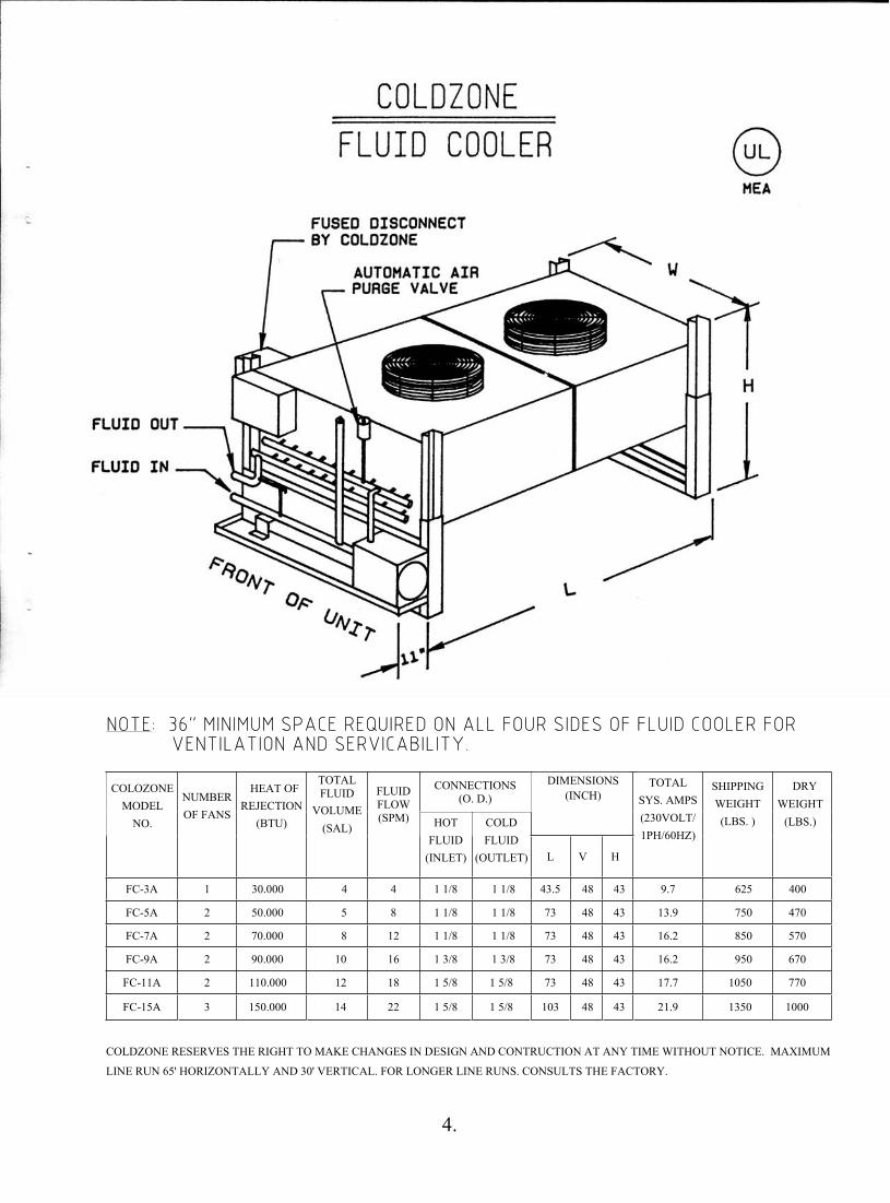
NNOOTTEE:: 3366"" MMIINNIIMMUUMM SSPPAACCEE RREEQQUUIIRREEDD OONN AALLLL FFOOUURR SSIIDDEESS OOFF FFLLUUIIDD CCOOOOLLEERR FFOORR VVEENNTTIILLAATTIIOONN AANNDD SSEERRVVIICCAABBIILLIITTYY..
CONNECTIONS (O. D.)
DIMENSIONS (INCH) COLOZONE
MODEL NO.
NUMBER OF FANS
HEAT OF REJECTION
(BTU)
TOTAL FLUID
VOLUME (SAL)
FLUID FLOW (SPM) HOT
FLUID(INLET)
COLDFLUID
(OUTLET) L V H
TOTAL SYS. AMPS (230VOLT/ 1PH/60HZ)
SHIPPINGWEIGHT (LBS. )
DRYWEIGHT
(LBS.)
FC-3A 1 30.000 4 4 1 1/8 1 1/8 43.5 48 43 9.7 625 400
FC-5A 2 50.000 5 8 1 1/8 1 1/8 73 48 43 13.9 750 470
FC-7A 2 70.000 8 12 1 1/8 1 1/8 73 48 43 16.2 850 570
FC-9A 2 90.000 10 16 1 3/8 1 3/8 73 48 43 16.2 950 670
FC-11A 2 110.000 12 18 1 5/8 1 5/8 73 48 43 17.7 1050 770
FC-15A 3 150.000 14 22 1 5/8 1 5/8 103 48 43 21.9 1350 1000
COLDZONE RESERVES THE RIGHT TO MAKE CHANGES IN DESIGN AND CONTRUCTION AT ANY TIME WITHOUT NOTICE. MAXIMUM
LINE RUN 65' HORIZONTALLY AND 30' VERTICAL. FOR LONGER LINE RUNS. CONSULTS THE FACTORY.
4.
INSTALLATION
RECEIPT AND INSPECTION OF EQUIPMENT Inspect the Fluid Cooler unit and all accessories shipped with it for any damage or shortages. Any damage or shortages should be reported immediately to the delivering carrier. Damaged material becomes the delivering carrier's responsibility and it should not be returned to the manufacturer without prior approval from our service manager and a return material authorization number.
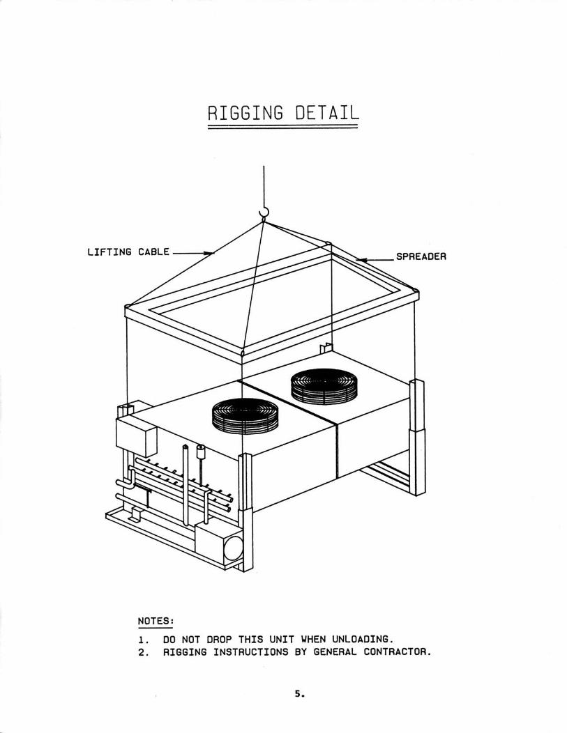
LIFTING INSTRUCTIONS Careful consideration of lifting procedures should be made before the unit is lifted by any means. Particularly, any cables or other load-bearing devices must not be allowed to press against piping, electrical conduit of the motor control panel. The only part of the unit designed to carry any of the lifting load is the base. Lifting loads should be distribute evenly around the base to avoid any twisting.
It is recommended that whenever the unit is lifted by a crane, the lifting space provided in the lower portion of the base frame be used as attachment points for the lifting cables as shown in Figure 2. The lifting cables should be prevented from contacting the unit by means of a spreader or similar device.
LOCATION AND VENTILATION The Fluid Cooler must be located in an area which allows easy access for installation and servicer of all electrical lines, refrigeration piping and any accessory equipment. The unit must be level to insure proper lubrication. A minimum of 3 feet clearance must be provided on all sides of the unit.
INSTALLATION AREA Page 4 illustrates the overall dimension and installation requirements.
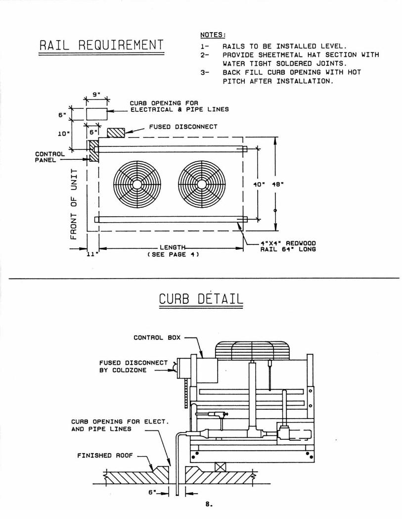
ROOF RAIL REQUIREMENTS The total weight of the complete unit is shown on (Page 4). The location and installation of all equipment should be in accordance with all local code requirements. ColdZone recommends the unit be placed directly upon two (2) 4" x 4" redwood rails. For light roof construction, vibration isolation pads can be used underneath the supporting frame.
PITCH POCKET A 6" x 9" pitch pocket must be provided for electrical and glycol lines. After lines are installed, backfill opening with not pitch to prevent water leakage into the building.
6.
ELECTRICAL To insure proper operation of equipment and reduce the possibility of electrical power interruption, the following precautions must be observed:
1. All electrical work must be done in accordance with the National Electrical Code and existing local codes.
2. The power supply must be the same as that which appears on the data plate of the motors.
3. An adequate power supply must be provided. 4. Voltage fluctuations in excess of plus or minus 10% should be corrected.
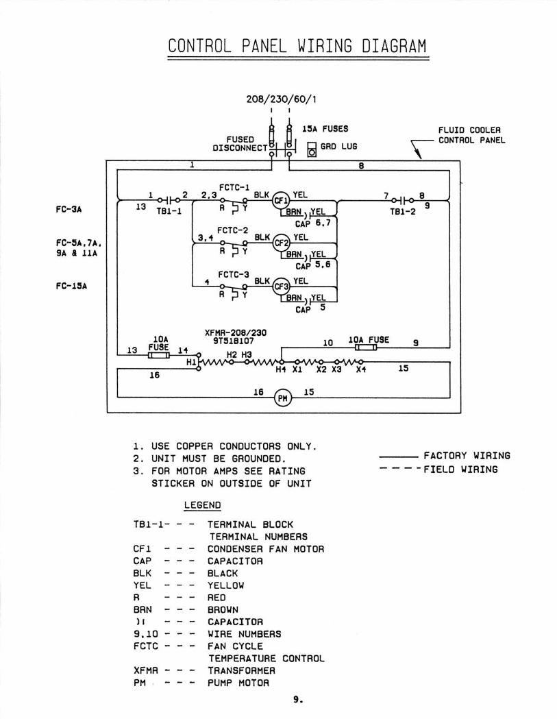
Before starting a Fluid Cooler, check that all breakers and motor protective devices are in place and that all wiring is secure. A complete wiring diagram for trouble-shooting the unit is included.
WARNING: PRIME PUMP BEFORE STARTING UNIT 1. Piping
Connect red return and blue supply lines to manifold sets at machines.
Piping must be adequately supported with hangers that can withstand the combined weight of tubing, and fluid in the tubing.
2. Leak Testing
After both glycol lines are connected, the entire system must be leak tested. Particular care should be given to those parts which will be inaccessible at a later date.
7.
START-UP PROCEDURE
After the installation has been completed, the following procedure must be covered to insure start-up:
1. Make sure the city water inlet and city water outlet valves on the manifold are closed. The inlet and outlet valves to the fluid cooler on the manifold and the inlet and outlet valves for each soft serve machines must be open
2. Fill the fluid cooler at the top of the reservoir. DO NOT START PUMP. Remove the cap at the top of the automatic air vent and manually depress the shader valve as you fill the system, this will purge air from the system. When all of the air has been purged manually then the pump may be primed by opening the bleed valve on the impeller housing,. The reservoir should be 3/4 full.
3. Start the pump.
4. Close all the inlet and outlet valves to the individual soft serve machines, except the machine farthest away (end of the manifold). Now start-up this soft serve machine. Once it is operating properly, shut this machine off, close the inlet and outlet valves at the manifold. Move to the next soft serve machine open valves on manifold and start up. Check fluid level in Fluid Cooler. Repeat this procedure until all machines are started. Now open all the inlet and outlet valves to the individual soft serve machines. Note: Isolating and starting up one (1) soft serve machine at a time will speed up the air purging process purging process.
5. Check fluid level in Fluid Cooler.
6. Check amperage and voltage draw on pump motor to be sure motor is not overload. Compare to data plate.
7. Check fan for proper vertical air flow.
MECHANICAL SEAL
Pumps are furnished with a precision mechanical seal. This seal is installed and checked at the factory and should require no adjustment at the time of the installation. Running the pump without a glycol solution will result in rapid seal failure.
After the pump has been in service for a long period of time, it may be necessary to replace this seal (the seal may leak). Leakage can be detected by a dripping of liquid from the area around the motor shaft.
CAUTION: THE PRECISION LAPPED FACES ON THE MECHANICAL SEAL ARE EASILY DAMAGED. HANDLE YOUR REPLACEMENT SEAL CAREFULLY AND READ THESE INSTRUCTIONS BEFORE ATTEMPTING TO REPLACE THE SEAL. RUN PUMP DRY, AS PERMANENT DAMAGE TO MECHANICAL SEAL WILL RESULT.
ColdZone provides 100% propylene glycol. Field mixing is required.
10.
MAINTENANCE
Inspect the unit regularly for loose bolts and connections, rust and corrosion and dirty or clogged heat transfer surface (cooling coil). Check all lines for leaks and deformation.
HEAT TRANSFER SURFACE Dirt and dust should be removed by brushing the fins and tubes and blowing loose dirt off with an air hose. Should the surface be greasy, the motor should be removed and the fins and tubes brushed or sprayed with a mild alkaline solution or a nonflammable de-greasing fluid. Follow up with a hot water rinse and dry thoroughly.
ELECTRIC MOTOR
Properly selected and installed pump and fan electric motors are capable of operating for years with minimal maintenance. Periodically clean dirt accumulations from open type motors, especially in and around vent openings, preferably by vacuuming (avoid embedding dirt in windings). Check running amps and voltage. Fan and pump motor is provided with sealed ball beatings. Re-lubrication of the bearings is not normally required.
REPAIRS OR REPLACEMENT OF PARTS
When ordering replace parts or making inquiry regarding service, have the mo del number and serial numbers handy. Any reference to tie motor must carry serial and model numbers.
REMOVAL OF OLD SEAL 1.Disassemble the centrifugal housing from the pump by removing the five
hex head cap-screws.
2. Unscrew the impeller. A screwdriver slot is provided in the rear end of the motor shaft (remove bearing cap for access). To hold the shaft from turning, insert a large screw driver blade into the slot. Thread is standard right hand thread. Turn the impeller counter clockwise to remove.
3. Grasp the sintered iron seat (Ref. #5) and slip from the motor shaft.
4. Remove the pump body from the motor by removing the four (4) hex head cap-screws.
5. Remove the spring seal by pushing from the direction of the pump body mounting flange. Care must be exercised with pusher so as not to damage the seal cavity area.
11.
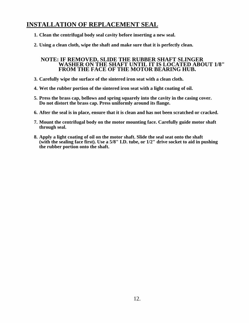
INSTALLATION OF REPLACEMENT SEAL 1. Clean the centrifugal body seal cavity before inserting a new seal.
2. Using a clean cloth, wipe the shaft and make sure that it is perfectly clean.
NOTE: IF REMOVED, SLIDE THE RUBBER SHAFT SLINGER WASHER ON THE SHAFT UNTIL IT IS LOCATED ABOUT 1/8" FROM THE FACE OF THE MOTOR BEARING HUB.
3. Carefully wipe the surface of the sintered iron seat with a clean cloth.
4. Wet the rubber portion of the sintered iron seat with a light coating of oil.
5. Press the brass cap, bellows and spring squarely into the cavity in the casing cover. Do not distort the brass cap. Press uniformly around its flange.
6. After the seal is in place, ensure that it is clean and has not been scratched or cracked.
7. Mount the centrifugal body on the motor mounting face. Carefully guide motor shaft through seal.
8. Apply a light coating of oil on the motor shaft. Slide the seal seat onto the shaft (with the sealing face first). Use a 5/8" I.D. tube, or 1/2" drive socket to aid in pushing the rubber portion onto the shaft.
12.
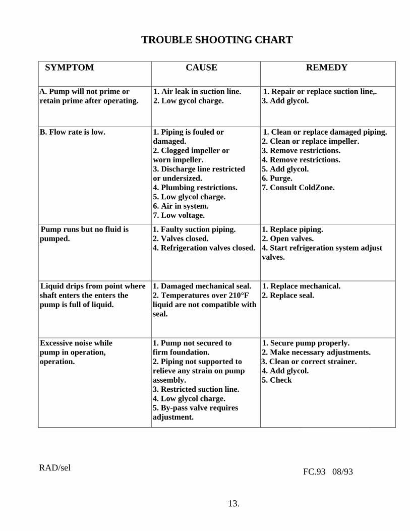
TROUBLE SHOOTING CHART
SYMPTOM CAUSE REMEDY
A. Pump will not prime or retain prime after operating.
1. Air leak in suction line. 2. Low gycol charge.
1. Repair or replace suction line,. 3. Add glycol.
B. Flow rate is low. 1. Piping is fouled or damaged. 2. Clogged impeller or worn impeller. 3. Discharge line restricted or undersized. 4. Plumbing restrictions. 5. Low glycol charge. 6. Air in system. 7. Low voltage.
1. Clean or replace damaged piping. 2. Clean or replace impeller. 3. Remove restrictions. 4. Remove restrictions. 5. Add glycol. 6. Purge. 7. Consult ColdZone.
Pump runs but no fluid is pumped.
1. Faulty suction piping. 2. Valves closed. 4. Refrigeration valves closed.
1. Replace piping. 2. Open valves. 4. Start refrigeration system adjust valves.
Liquid drips from point where shaft enters the enters the pump is full of liquid.
1. Damaged mechanical seal. 2. Temperatures over 210°F liquid are not compatible with seal.
1. Replace mechanical. 2. Replace seal.
Excessive noise while pump in operation, operation.
1. Pump not secured to firm foundation. 2. Piping not supported to relieve any strain on pump assembly. 3. Restricted suction line. 4. Low glycol charge. 5. By-pass valve requires adjustment.
1. Secure pump properly. 2. Make necessary adjustments. 3. Clean or correct strainer. 4. Add glycol. 5. Check
RAD/sel
FC.93 08/93
13.
4/97
ColdZone
LIMITED WARRANTY
ColdZone warrants, to the original purchaser, each product to be free from defects in material and workmanship if installed and used in compliance with ColdZone preparatory start-up procedure. The limited warranty is effective for period of twelve (12) months from the date of start-up and is not to exceed fifteen (15) months from the date of seller's invoice. Under the terms of this warranty, ColdZone will, repair or replace, at seller's option, any part(s) which, when returned in sealed containers, tagged as to serial and model numbers, with transportation charges prepaid to the factory or service location designated by ColdZone proves to be defective.
ColdZone assumes NO responsibility for incidental or consequential damages, including, but not limited to, refrigerant, labor, taxes, food loss, service charges, lost profits, injury to person(s) or property, travel expenses, acts of God, etc...
This warranty does not apply to equipment that has been damaged in transit, altered, abused, or where ColdZone service and installation requirements are not met. Replaced parts warranty expires on original product warranty expiration.
As each compressor sold by ColdZone is warranted by the compressor manufacturer, replacement during the first year of operation must be made through an authorized wholesaler. ColdZone extends the manufacturer's warranties to its customers.
ColdZone includes a sequentially numbered preparation/start-up procedure in each unit shipped. This preparation/start-up procedure must be completed and returned to "Attn.: Service Manager," via certified mail to activate the limited warranty.
ColdZone neither assumes nor authorizes any person(s) to assume for seller any obligation or warranty other than that which is stated in this warranty.
This warranty is valid only after all financial obligations to ColdZone have been paid.
ColdZone is solely responsible for this warranty and makes no other warranty, either expressed or implied. All implied warranties or merchantability and fitness for a particular purpose which exceed ColdZone obligations are hereby disclaimed and excluded from this warranty.
ColdZone must be notified of any claim against this warranty within 120 days of the occurrence, with the stipulation that this notification is not made more than thirty (30) days after the expiration of this warranty. Claims made beyond these time frames will not be honored.
P.O. Box 1030 • Brea, CA 92822-1030 • 221 South Berry Street • Brea, CA 92821 Phone: 714/529-4461 • 800/772-2653 • Fax: 714/529-8503