owner’s manual for chemstar vacuum pumps · pdf fileowner’s manual for...
TRANSCRIPT
OWNER’S MANUALFOR
CHEMSTAR® VACUUM PUMPSMODELS:
1374N1376N1400N1402N
Contents: InstallationOperationMaintenanceWarrantyMSDS Sheet For Pump OilSpecificationsParts List and Expl. ViewsApplications Booklet
WARNINGNever Block the Exhaust Port. If the exhaust is blocked, pressure
will build-up in the pump with the potential of the pump bodybursting and causing possible injury to personnel in the area.
Welch Rietschle Thomas7301 North Central AvenueSkokie, IL 60077Phone: (847) 676-8800Fax: (847) 677-8606 (Technical Support)Fax: (920) 451-4397 (Ordering)E-Mail: [email protected] Part No. 67-0544R3.2Web-Page: www.welchvacuum.com Printed in USA
For outside U.S. and Canada, contact your localRietschle Thomas sales office, see back page

CHEMSTAR® OWNERS MANUALCONTENTS
Section Page
1. Installation 32. Operation 63. Maintenance 84. Quick Reference Charts 105. Pumping Speed Curves 106. Dimensional Drawings (with rotation) 117 Exploded Parts Listing 128. MSDS for Welch 8995G Gold Vacuum Pump Oil 209. Accessory Section 2211. Application Booklet – CHEMSTAR® and Corrosive Gases 2312. Warranty Information 36
Stainless Steel ISO NW Intake and Exhaust Fittings
The Pumps come with ISO NW fitting on both the intake and exhaust ports. The fittings make it easy touse Welch modular piping to connect the pump to your system and allow easy disassembly. For users whoprefer to use rubber hose, a rubber hose adapter for the intake fitting is provided.
Be sure prior to start-up, you have properly identified the intake port on the pump (see Schematics Below).NEVER BLOCK THE EXHAUST PORT. If the exhaust port is blocked, this will lead to a pressure buildup in the pump resulting in the pump body bursting and possible injury to the pump operator. Be sure to callWelch technical service prior to start-up at (847)-676-8800 if you have any questions.
INTAKE PORT
1400N-01 1402N-01 1376N-01 1374N-01

Section 1: INSTALLATION
1.1 IntroductionThis manual has been compiled not only for the care and maintenance of the CHEMSTAR pump now in yourpossession but as a helpful reference and guide for many problems which are usually associated with mechanicalvacuum pumps. Take time to read these instructions carefully and preserve this manual for future reference; wethink it will be useful to you.
1.2 UnpackingCarefully remove the pump from the shipping case and unfasten and remove the wooden skid. Preserve all paperwork and inspection tags for future reference. If damage has occurred from shipment a claim must be filed withthe carrier immediately; preserve the shipping container for inspection by the carrier. If you are required tocommunicate with your dealer or with Welch Vacuum Technology, Inc. be sure to include your order numbers forquick identification. Do not return the pump to the factory without first calling for a returned goods number.
1.3 Pump Mounting1.3a Mounted pumpsRubber bumpers are supplied with most of our mounted pumps, either loosely or attached. Bumpers areexcellent for applications involving a semi-flexible surface such as a bench top; they help to isolate noise andeliminate creeping. For more rigid requirements the pump base may be bolted directly to a firm foundationwith or without the bumpers. All CHEMSTAR pumps should be mounted in a horizontal plane.
1.3b Unmounted PumpsIf you have purchased an unmounted pump, refer to parts list for information concerning the motor, motorpulley and belt necessary to drive your particular pump at the recommended speed.
1.4 Pump LocationThe pump should be located preferably in a clean and well ventilated area and adequate space should beprovided wherever possible for routine maintenance such as changes of oil and belt adjustments and re-placements. Above all, the pump should be located as closely as possible to its system in order to utilize itmost efficiently. Its locations should include such determining factors as the length and size of connections,the number of bends and the type of exhaust connections.
1.5 Exhaust ProvisionsExhaust connections will be determined by the type of system to be exhausted and the desired cleanliness of theatmosphere surrounding the pump. SEE APPLICATION BOOKLET WITHIN OWNER’S MANUALFOR COMPLETE DETAILS ON OIL MIST ELIMINATORS AND EXHAUST SYSTEMS FORCORROSIVE GASES.
1.6 Electrical Power1.6a Power Source ReviewReview the power source and the motor rating to be sure they agree in voltage, phase and frequently. Onthree-phase applications the direction of rotation of the motor must be considered. Make a momentarycheck of rotation at the time of power installation and wiring. Momentary backward rotation of the pump isnot harmful. Check the layout drawings for proper direction of rotation.
Identification Symbols:
1.6b Overload ProtectionMotor thermal overload protection is made available by the motor manufacturer as an aid to minimizingmotor failure. Overload protection is a standard feature on all single-phase 60 Hz motors. Single-phasemotors will normally have automatic overload protection. Motors of 1-1/2 horsepower or large suppliedwith DuoSeal pumps contain no overload protection. Installations of such equipment must comply withlocal electrical codes which dictage appropriate starter and protection devices. It is strongly suggestedthat you familiarize yourself with the protection supplied with your motor so that you may react accord-ingly in the event of an emergency. Automatic reset protection is designed to rest itself after a predeter-mined cooling period. If the fault to the drive remains unaltered, the motor will cycle on and off until thefault is corrected. The motor data plate will indicate the presence of thermal protection.
1.7 Vacuum Connections1.7a Choice of ConnectionsThe choice of connections and fittings can have a very marked effect on the pumping speed at thevacuum chamber. Any connection placed between the pump and the chamber creates an impedance tothe flow of gas. This is particularly true at low pressures in the millitorr range where the gas flow issubstantially molecular in character. The gas flow isthen dependent upon the kinetic activity of themolecules to bring it to the intake of the pump.
1.7b The Effects of ConductanceIt has been show that the conductance of a tube is proportional to the cube of its diameter and inversely proportional toits length. Therefore it is imperative that the connecting lines be as large in diameter and as short in length as practical.For best results the diameter of the connecting tube should be at least as large as the diameter of the pump intake. Toavoid a large reduction in pumping speed at the vacuum chamber, it is clear that the conductance of the line must beconsiderably greater than the speed of the pump.
1.7c Metal JointsIf metal piping or tubing is used, it is preferable to solder or braze all the connections. Where threadedjoints must be used, coat the threads with LocTite Thread Sealant with Teflon and screw together tightly.Flanged connections with elastomer gaskets make excellent demontable joints. Modular vacuum pipingand fittings are now extensively used.
1.7d Rubber Tubing JointsWhere metal tubing is used between the system and the pump intake, joints can be made by butting the ends ofthe two sections together in a short section of rubber vacuum hose. Worm-screw band clamps are useful forsecuring the hose to the tubing. Whatever the joint you choose to use, cleanliness should be of utmost impor-tance.
1.7e Valves and StopcocksMetal valves or stopcocks may be used in the connecting line between the system and the pump to provide ameans of isolating the pump from the system. To minimize the impedance of flow, the valve openings should beas large as possible. Lubricate the rotating plug of the stopcock with a film of vacuum grease sufficiently thickenough to prevent seizure.

1.8 Vacuum GaugesThe type of vacuum gauge to be used is determined largely by the pressure range to be measured. Pressures in theranges produced by CHEMSTAR pumps can be covered by McLeod, Thermistor, Pirani or Thermocuple gauges. TheMcLeod gauge is used where high accuracy of measurement is required. The Pirani, Thermistor and Thermocouplegauges are electrical and give continuos readings of the total pressure. They are preferred where rapid pressurechanges occur. The McLeod gauge does not measure condensable vapors; therefore, if vapors are present it willgenerally read lower in pressure than electrical gauges. For higher vacuums in systems employing diffusion, turbo-molecular or ion pumps, the hot filament ionization of the Philips gauge is used.
1.9 Traps1.9a The Need for a TrapWhere corrosive vapors or large quantities of condensable vapors are evolved from vacuum processing, a coldtrap may be used in the connecting line to the pump. It will help prevent damage to the pump mechanism andreduce oil contamination. The cold trap, immersed in a suitable Dewier flask, is installed so that the vapors maycome in contact with the surfaces of the trap and condense. Commonly used refrigerants are liquid nitrogen ordry ice and acetone. The refrigerant to be used depends upon the freezing point of the contaminants. A varietyof cold traps are available from Welsh Vacuum Technology, Inc. SEE APPLICATION BOOKLET WITHINMANUAL THAT PROVIDES ADDITIONAL DETAILS ON WHEN TO USE TRAPS.
1.9b The Care of a TrapWhen using a cold trap the refrigerant should be maintained at a high level in the flask to keep the trap at auniformly low temperature. If the trap is rewarded it may allow re-evaporation of the condense. The refrigerantadd tube on the liquid nitrogen trap should not be obstructed as the refrigerant boil-off can produce dangerouslyhigh pressures. If the trap becomes saturated it should be disconnected from the system, drained and cleaned.An increase in pressure in the vacuum system will normally indicate that the trap has become saturated. To cleanthe trap, remove the trap from the system, allow the trap to warm up and rinse off the condense with a suitablesolvent in a fume hood. Thoroughly clean and dry the trap before reinstalling in the system.
1.10 Types Of LubricantsAll CHEMSTAR mechanical vacuum pumps are normally tested with DIRECTORR Gold oil and shipped with afull charge to prevent unnecessary contamination. An additional supply of oil is furnished with each pump withinstructions to drain and discard the oil contaminated in the pump and replace with the fresh oil. DIRECTORRGold oil has been especially prepared and is ideally suited for use in mechanical vacuum pumps because of itsdesirable viscosity, low vapor pressure and chemical stability.
The vacuum guarantee on all CHEMSTAR pumps applies only when DIRECTORR gold oil is used. Otherlubricants for special applications are available including various lubricants for oxygen compatibility, lubricants foruse with diffusion pumps as well as other special requirements. SEE APPLICATIONS BOOKLET INOWNERS MANUAL FOR OTHER LUBRICANTS USED FOR SPECIAL APPLICATIONS SUCHAS OXYGEN SERVICE.

Section 2: OPERATION
2.1 Starting Procedures2.1a Starting a CHEMSTAR PumpBefore attaching the pump to a system it is well to familiarize yourself with the function and action of the pumpwhich you have now acquired. Remove the intake and exhaust port plugs and temporarily provide a stopper forthe intake and a dust cap for the exhaust. Review the power requirements as described in Paragraph 1.6.
2.1b CleanlinessTake every precaution to prevent foreign particles from entering the pump. A fine mesh screen is provided forthis purpose in the intake passage of all CHEMSTAR pumps.
2.2 Leak Detection2.2a Large LeaksThe importance of eliminating all leaks in a vacuum system is obvious when it is realized that a leak into thesystem, at atmospheric pressure, expands in volume by a factor of 750,000 to 10,000,000 or more. The pumpmust remove this added volume to maintain the desired vacuum. Fortunately a number of effective techniquesfor leak detection have been developed. Large leaks can be located by pressurizing the system and painting thesuspected area with a thick soap solution. Escaping air will produce soap bubbles.
2.2b Small LeaksSmall leaks may also be detected by spraying a suspected area with acetone or gases rich in hydrogen, andobserving a sudden change in pressure on an electrical gauge. The difference in calibration of these gauges, forair and other gases, will produce a distinct change in the pressure reading. To use this method of detection, thesystem must be under vacuum and the gauge sensing tube must be located between the pump and the area to beprobed. Use extreme caution, as these materials are highly flammable!
2.2c Fine LeaksLocating very fine leaks requires a helium-sensitive, mass-spectrometer leak detector. This instrument willlocate leaks which cannot be detected by any other method. Numerous fine leaks can have the total effect of alarge leak.
2.3 Shutdown Procdures2.3a CHEMSTAR Pump ShutdownA few simple precautions are all that is necessary when a shutdown is in order. If a gauge is connected to thesystem, first isolate the gauge, then turn off the power and open the system to atmosphere. If the pumps removedfrom the system, over the intake port with a rubber stopper or suitable cover to protect the pump against contami-nation and loose particles. If the pump has been contaminated in service and is going to be shelved for aprolonged period it is best to drain the oil and refill with a fresh charge.
2.4 The Principle of Gas Ballast2.4a The Effects of Unwanted VaporSystems which contain undesirable vapors cause difficulty both from the standpoint of attaining desirable ultimatepressures as well as contamination of the lubricating medium. A vapor is defined as the gaseous form of anysubstance which is usually a liquid or a solid. Water, oil and mercury vapors are three of the more commonvapors encountered in typical vacuum systems. When such vapors exist in a system, the vapors or mixtures ofgas and vapor are subject to condensation within the pump; the precipitated liquid may thus ultimately dissolve orbecome emulsified with the lubricating medium. This emulsion is recirculated to the chambers of the pump whereit is again volatilized causing increased pressure within the system.
2.4b The Presence and Removal of CondensateCondensation takes place particularly in the compression stroke of the backing or second stage of a two-stagepump. The compression stroke is that portion of the cycle during which the gas drawn from the intake port iscompressed to the pressure necessary to expel it past the exhaust valve. Condensation takes place when theratio between the initial pressure and the end pressure is compressed from a low pressure to a high pressure. Byadding air through the gas ballast valve to the mixture of vapor and gas being compressed, the pressure requiredfor delivery past the exhaust valve is reached with a considerably smaller reduction of the volume of the mixture;thus, depending upon the amount of air added, condensation of the vapor is either entirely avoided or substantiallyreduced.
2.4c Pump Function Without Gas BallastIn a pump functioning on a contaminated system and operating without the gas ballast, compression within thestage takes place in the normal manner until the saturation pressure of the contaminating vapor contained withinthe mixture of gas and vapor is reached. The saturation pressure of water is that pressure and correspondingtemperature at which the dew point of the vapor is reached and condensation occurs. The saturation pressure ofwater vapor at an ambient temperature of 20C is 17.5 torr, while at 60C, the approximate operating temperatureof a pump, the saturation pressure is 149 torr. The external side of the exhaust valve is subjected to atmosphericpressure. Consequently a compressive force somewhat greater than atmospheric pressure is required to openthe valve and permit expulsion of the gas. Sometime during increased compression of the mixture of gas andvapors, the saturation pressure of 149 torr for the water vapor is reached and the vapor condenses. The conden-sate is then allowed to emulsify with the oil which is recirculated within the pump stages thus providing continuedcontamination of the system.
2.4d Pump Function with Gas BallastOn the other hand, when ballast air at atmospheric pressure is supplied to the compression stroke by means of thegas ballast, the partial pressure of the unwanted vapor becomes a very small part of the total pressure of themixture of gas, vapor and newly supplied air. The vapor is thus prevented from reaching its saturation pressurecorresponding to the temperature of the pump and is finally expelled from the pump as a vapor.
2.4e Controlled Ballast FlowSome degree of variation in ballast flow may be obtained by the amount of opening applied to the gas ballast. Two ormore turns of the gas ballast are sufficient to open it wide. With the gas ballast open, the sound of the exhaust is similarto that of a pump operating against a large leak. Because of the increased pressure introduced into the compressionstroke, the pump must work a little hard to function, thus resulting in an increased operating temperature of approxi-mately 8C over a prolonged period of time. Tests have shown that continuous and prolonged operation for severalweeks under these conditions is not injurious to the pump.
2.4f Other Forms of Contamination ControlThe application of the gas ballast is a moderate and very successful method for the removal of condensablevapors. For very heavily laden systems, other means of removal such as oil separators may be required. For mildcases of contamination the simple expedient of a cold trap or a change of oil may serve the purpose.

Section 3: MAINTENANCE
3.1 Vacuum Problems3.1a Pressure DeterminationsLeakage, contamination and unusual outgassing are the general causes of problems associated with poor vacuum.To operate at maximum efficiency a system must be thoroughly clean. If the system is completely clean and freefrom leaks, and unwarranted vacuum problems still exist, the pump should be checked. A simple criterion for thecondition of a mechanical pump is a determination of its ultimate pressure capability. This can be accomplishedby attaching a gauge directly to the pump. The gauge may be any suitable type provided consideration is given tothe limitations of the gauge being used. Refer to Paragraph 1.8 for further suggestions. If the pressure isunusually high, the pump may be badly contaminated, low on oil or malfunctioning. On the other hand, if thepressure is only slightly higher than the guaranteed pressure of the pump, an oil change may be all that is required.
3.1b Oil ContaminationThe most common cause of a loss in efficiency in a mechanical pump is contamination of oil. It is caused bycondensation of vapors and by foreign particles. The undesirable condensate emulsifies with the oil which isrecirculated and subjected to re-evaporation during the normal cycle of pump activity thus reducing the ultimatevacuum attainable. Some foreign particles and vapors may form sludges with the oil, impair sealing and lubrica-tion and cause eventual seizure. A gas ballast valve is helpful in removing vapors, especially water, but it is notequally effective on all foreign substances; therefore, periodic oil changes will vary with the particular system.Experience with the process will help you determine the normal period of operation before an oil change isrequired. SEE APPLICATION BOOKLET WITHIN MANUAL THAT PROVIDES ADDITIONALDETAILS ON PREVENTING OIL CONTAMINATION.
3.1c Oil OverheatingThis pump designed to operate continuously below 10 Torr. Continuous operation of this pump above 10 Torr willlead to overheating and eventual pump failure.
3.2 Oil Changes and Oil Level3.2a Draining the PumpAn oil change is mot easily accomplished when the pump is warm and the oil is less viscous. Use a containerlarge enough for the oil in the particular pump. Stop the pump, and open the drain valve. A thorough job may beaccomplished by tipping the pump slightly if this is possible. The small residue remaining in the pump may beforced out by hand-rotating the pump pulley with the exhaust port partially closed and the intake port open.Closing the exhaust port completely under these conditions will create excessive pressure at the drain valvewhich may cause the oil being drained to splatter.
3.2b Flushing the Pump
SEE APPLICATION BOOKLET WITHIN OWNER’S MANUAL THAT DESCRIBES FORCED OILFLUSHING PROCEDURES TO REMOVE CONTAMINANTS FROM PUMPING MECHANISM.
3.2c Refilling the PumpAfter you are satisfied that the pump has been thoroughly flushed, refill the pump by puring new DIRECTORRGold oil into the exhaust port. Fill to the indicated level and start the pump with the intake closed. A gurgling noiseis characteristic when high pressure air is drawn through the pump. It should disappear quickly as the pressurewithin the pump is reduced. If gurgling continues, add sufficient additional oil through the exhaust port untilgurgling ceases.

3.3 Repairing Oil Leaks3.3a Location, Cause and Effect
Oil leaks may develop wherever two mating faces are sealed with a gasket. Such seams may fail as the result ofdeterioration of the gasket material, loosening of the screws caused by temperature variations, or improper careas the result of previous reassembly. Typical gasketed seams in a mechanical pump are located at the oil levelwindow, the shaft seal, the oil drain, and the mating faces of such mechanical surfaces as the intake chambercover, the oil case, and the exhaust chamber cover. The important of a gasketed seam is determined principallyby its function. If it is a vacuum seal, the ultimate performance of the pump is dependent upon it. If it is an oilseal, the pump may be operated satisfactorily for some time without loss of function. Eventually, of course, agreat loss of oil may cause harmful damage.
3.3b Repairing TechniqueAn oil seam may be sealed by any of several methods. When an O-ring is employed, the surfaces of the O-ringand its groove should be wiped clean. If the O-ring is not badly deformed or scratched it may be reused bysealing with a slight film of vacuum oil or vacuum grease. Thin composition gaskets are generally used for largeirregularly shaped areas. A replacement joint of this type should be thoroughly cleaned of all previous gasketmaterial and the mating surfaces cleaned of any nicks.
3.4 Repairing Vacuum Leaks3.4a Surface PreparationGood vacuum seals are an essential and important attribute of a good mechanical pump. A good seal is dependentupon the quality of the mating surfaces as well as the sealant and its preparation. The mating faces should becarefully inspected for any projections or foreign particles which might interfere with proper mating. Slightprojections such as nicks and burrs are most easily removed by rubbing with a fine abrasive stone. The surfaceof the mating parts may be washed with a solvent or alcohol after which they must be thoroughly dried.
3.4b Temporary RepairTemporary vacuum repairs are often made by covering the known leak with an industrial sealant such as Loctitewith teflon. Such a practice, however, is not recommended for seals of a permanent nature.
3.5 Drive ProblemsIf for any reason the pump will not operate, turn off the power and check the fuse and electrical connections.Then try the power to the motor only by removing the belt. If the motor operates properly try hand-rotating thepump in the proper direction with the pump intake port open. If both turn freely then replace the belt tension. Thetension should be sufficient to drive the pump without visible slippage. Any greater tension will cause noise andpossible damage to the bearings of both the motor and pump. Make certain that both pulley grooves are clean andfree from oil. The pulleys must be fastened securely on their respective shafts, and in parallel alignment.

Section 4: QUICK REFERENCE CHARTS
Section 5: PUMPING SPEED CURVES
HIGH EFFICIENCY PUMPING CHARACTERISTIC OF DUOSEAL® PUMPS
The low RPM design of DuoSeal vacuum pumps makes it possible to maintain high pumingefficiencies into the low micron range. High RPM direct drive vacuum pumps, on the otherhand, experience a rapid fall off of pumping speed below 100 microns.
A comparison of the DuoSeal pumping speed curves shown below, versus high RPM pumpspeed curves conclusively illustrates the superior performance of the DuoSeal pump.
What does that mean for the vacuum pump user? DuoSeal pumps provide considerablefaster pumpdown in the low micron range.
Vacuum Pump 1400N
Vacuum Pump 1376N/1402N
Vacuum Pump 1374N
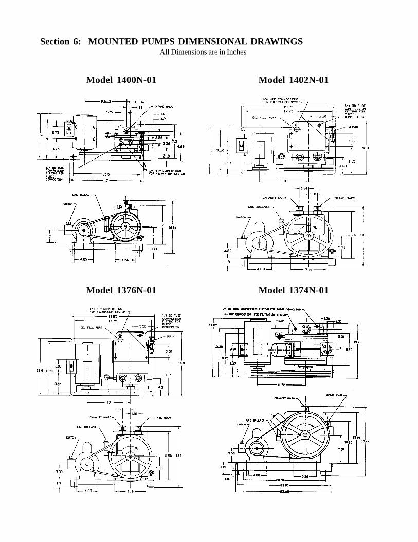
Section 6: MOUNTED PUMPS DIMENSIONAL DRAWINGSAll Dimensions are in Inches
Model 1400N-01 Model 1402N-01
Model 1376N-01 Model 1374N-01

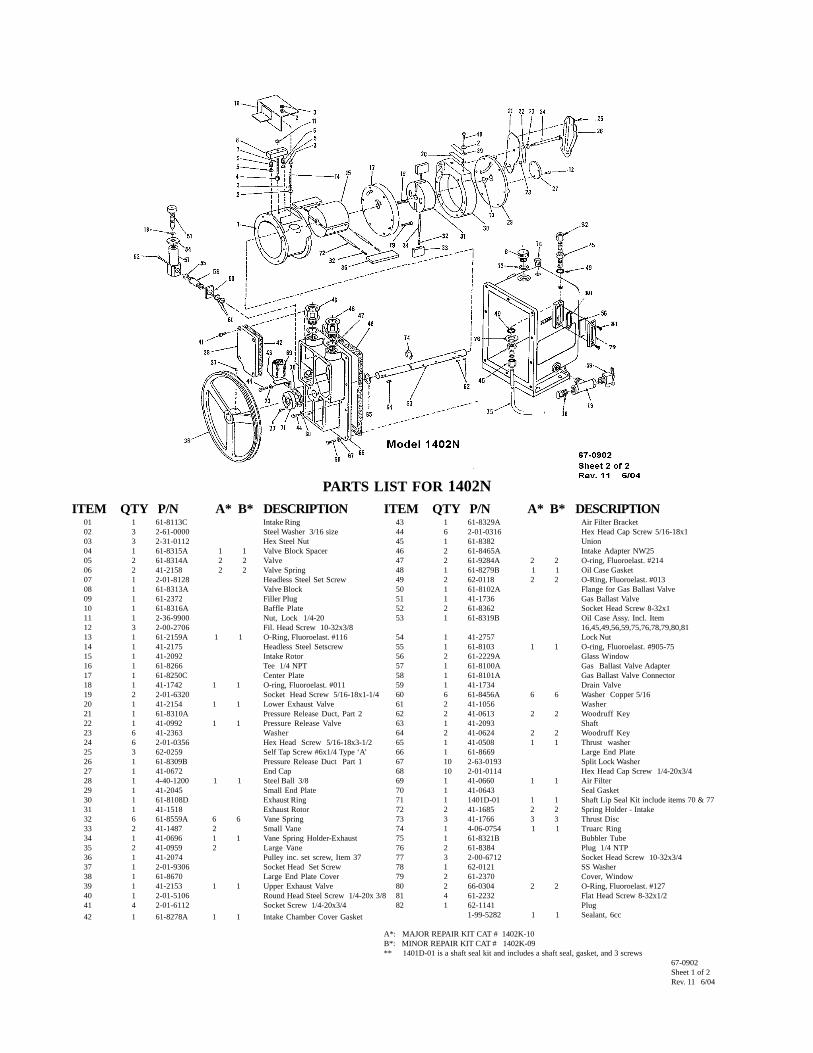
PARTS LIST FOR 1400NITEM QTY P/N A* B* DESCRIPTION1 1 2-01-9306 Soc. Hd. Screw 5/16 - 18x3/82 1 41-2191 Pulley Including Set Screw Item 13 1 41-3696 Shaft Seal4 1 41-0643 Shaft Seal Gasket5 1 41-0624 1 1 Pulley Key6 1 41-1060 Shaft7 1 41-1150 1 1 Retaining Ring8 2 41-0613 2 2 Woodruff Key9 1 2-00-2704 Fil. Hd. SS Screw 10-32x1/410 2 61-8682 Leg11 6 41-1138 Washer, Copper 7/16 OD12 1 41-3753 Oil Sight13 1 41-1742 1 1 O-Ring #01114 1 61-8548C Oil Case Assy. (see note below)15 2 61-8384 Plug, 1/4 NTP16 1 61-8355B 1 1 Oil Case Gasket17 9 2-01-0332 Hex. Hd. Cap Screw 5/16 - 18x1-1/218 9 41-2363 Washer19 1 41-1045 Back Endplate20 1 41-1040 Exhaust Rotor21 1 61-1239 1 1 Exhaust Valve22 2 2-71-0040 2 2 Brass Washer #1023 8 41-1056 Aluminum Washer24 1 41-1039 Vented Exhaust Plug25 1 61-8678 Center Plate26 1 41-1285 Steel Washer27 1 41-0890 1 1 Air Filter28 1 41-0383 1 1 Gasket, Intake Chamber29 1 61-8676 Intake Chamber30 2 61-8464A Adapter, NW1631 2 2-01-0524 Hex. Hd. Cap Screw 3/8 - 16x1-1/232 1 61-8701 Back Endplate33 1 61-8672 End Cap34 5 2-00-2706 Hex. Hd. Screw 10 - 32x3/835 2 2-31-2521 Hex. Nut 3/8x16
Note:Oil Case Assy. Item # 14 Includes Items # 10, 12, 15, 30, 48, 49, 52 , 54, 60, 61, 62, 65 & 66
A*: MAJOR REPAIR KIT CAT# 1400K-10B*: MINOR REPAIR KIT CAT# 1400K-09** 1401E-01 is a shaft seal repair kit, it includes a shaft seal, gasket, and 3 screws
ITEM QTY P/N A* B* DESCRIPTION36 1 61-8674 Intake Ring37 1 41-1041 Intake Rotor38 2 41-1063 2 2 Spring Holder39 4 61-8559A 4 4 Vane Spring40 4 41-1059 4 Vane, Metal41 5 2-01-0112 Hex. Hd.. Cap Screw 1/4 - 20x3/442 1 41-1042 Exhaust Ring43 3 2-00-6712 Soc Hd Screw 10-32x3/444 1 41-0578 1 1 Lip Seal45 1 61-8102A Flange For G.B. Valve46 1 61-8103 1 1 O-Ring Viton47 2 61-8362 Soc. Hd. Screw 8 - 32x148 1 61-8266 Tee 1/4 NTP49 1 41-1734 Drain Valve50 1 2-01-0120 Hex. Hd. Cap Screw 1/4 - 20x1-1/451 1 41-1736 Gas Ballast Valve incl. item 1352 4 2-01-0308 Hex. Hd. Screw 5/16 - 18x1/253 2 2-61-0571 Steel Washer .071 x 3/8 I.D.54 2 61-2159A 1 1 O-Ring, Viton #11655 1 61-8348A 1 1 Baffle Stud56 1 61-8347B Exhaust Baffle57 1 61-8100A Valve Adapter58 1 61-8101A Connector59 1 41-2757 Locknut60 2 62-0118 2 2 O-Ring, Tetr., #01361 1 61-8382 Union62 1 61-8327B Bubbler Tube65 1 62-0121 Washer, SS66 1 62-1141 Plug67 1 61-8665 1 1 O-Ring, M2 .5x86, Viton68 1 61-9378 1 1 O-Ring, #152, Viton69 1 66-0183 1 1 O-Ring, #120, Viton
1401E-01 1 1 Shaft Seal Kit**1-99-5282 1 1 Sealant, 6cc
67-0903Sheet 1 of 2Rev. 2 6/04
Section 7: PARTS LIST AND EXPLODED VIEWS
PARTS LIST FOR 1402NITEM QTY P/N A* B* DESCRIPTION
01 1 61-8113C Intake Ring02 3 2-61-0000 Steel Washer 3/16 size03 3 2-31-0112 Hex Steel Nut04 1 61-8315A 1 1 Valve Block Spacer05 2 61-8314A 2 2 Valve06 2 41-2158 2 2 Valve Spring07 1 2-01-8128 Headless Steel Set Screw08 1 61-8313A Valve Block09 1 61-2372 Filler Plug10 1 61-8316A Baffle Plate11 1 2-36-9900 Nut, Lock 1/4-2012 3 2-00-2706 Fil. Head Screw 10-32x3/813 1 61-2159A 1 1 O-Ring, Fluoroelast. #11614 1 41-2175 Headless Steel Setscrew15 1 41-2092 Intake Rotor16 1 61-8266 Tee 1/4 NPT17 1 61-8250C Center Plate18 1 41-1742 1 1 O-ring, Fluoroelast. #01119 2 2-01-6320 Socket Head Screw 5/16-18x1-1/420 1 41-2154 1 1 Lower Exhaust Valve21 1 61-8310A Pressure Release Duct, Part 222 1 41-0992 1 1 Pressure Release Valve23 6 41-2363 Washer24 6 2-01-0356 Hex Head Screw 5/16-18x3-1/225 3 62-0259 Self Tap Screw #6x1/4 Type ‘A’26 1 61-8309B Pressure Release Duct Part 127 1 41-0672 End Cap28 1 4-40-1200 1 1 Steel Ball 3/829 1 41-2045 Small End Plate30 1 61-8108D Exhaust Ring31 1 41-1518 Exhaust Rotor32 6 61-8559A 6 6 Vane Spring33 2 41-1487 2 Small Vane34 1 41-0696 1 1 Vane Spring Holder-Exhaust35 2 41-0959 2 Large Vane36 1 41-2074 Pulley inc. set screw, Item 3737 1 2-01-9306 Socket Head Set Screw38 1 61-8670 Large End Plate Cover39 1 41-2153 1 1 Upper Exhaust Valve40 1 2-01-5106 Round Head Steel Screw 1/4-20x 3/841 4 2-01-6112 Socket Screw 1/4-20x3/442 1 61-8278A 1 1 Intake Chamber Cover Gasket
ITEM QTY P/N A* B* DESCRIPTION43 1 61-8329A Air Filter Bracket44 6 2-01-0316 Hex Head Cap Screw 5/16-18x145 1 61-8382 Union46 2 61-8465A Intake Adapter NW2547 2 61-9284A 2 2 O-ring, Fluoroelast. #21448 1 61-8279B 1 1 Oil Case Gasket49 2 62-0118 2 2 O-Ring, Fluoroelast. #01350 1 61-8102A Flange for Gas Ballast Valve51 1 41-1736 Gas Ballast Valve52 2 61-8362 Socket Head Screw 8-32x153 1 61-8319B Oil Case Assy. Incl. Item
16,45,49,56,59,75,76,78,79,80,8154 1 41-2757 Lock Nut55 1 61-8103 1 1 O-ring, Fluoroelast. #905-7556 2 61-2229A Glass Window57 1 61-8100A Gas Ballast Valve Adapter58 1 61-8101A Gas Ballast Valve Connector59 1 41-1734 Drain Valve60 6 61-8456A 6 6 Washer Copper 5/1661 2 41-1056 Washer62 2 41-0613 2 2 Woodruff Key63 1 41-2093 Shaft64 2 41-0624 2 2 Woodruff Key65 1 41-0508 1 1 Thrust washer66 1 61-8669 Large End Plate67 10 2-63-0193 Split Lock Washer68 10 2-01-0114 Hex Head Cap Screw 1/4-20x3/469 1 41-0660 1 1 Air Filter70 1 41-0643 Seal Gasket71 1 1401D-01 1 1 Shaft Lip Seal Kit include items 70 & 7772 2 41-1685 2 2 Spring Holder - Intake73 3 41-1766 3 3 Thrust Disc74 1 4-06-0754 1 1 Truarc Ring75 1 61-8321B Bubbler Tube76 2 61-8384 Plug 1/4 NTP77 3 2-00-6712 Socket Head Screw 10-32x3/478 1 62-0121 SS Washer79 2 61-2370 Cover, Window80 2 66-0304 2 2 O-Ring, Fluoroelast. #12781 4 61-2232 Flat Head Screw 8-32x1/282 1 62-1141 Plug
1-99-5282 1 1 Sealant, 6cc
A*: MAJOR REPAIR KIT CAT # 1402K-10B*: MINOR REPAIR KIT CAT # 1402K-09** 1401D-01 is a shaft seal kit and includes a shaft seal, gasket, and 3 screws
67-0902Sheet 1 of 2Rev. 11 6/04

PARTS LIST FOR 1376NITEM QTY P/N A* B* DESCRIPTION
01 1 41-2074 Pulley incl. item 202 1 2-01-9306 Socket Head Set Screw 5/16-18x3/803 1 1401D-01 1 1 Shaft Lip Seal Kit includes items 4 & 5**04 1 41-0643 Seal Gasket05 3 2-00-2706 Fil. Head Screw 10-32x3/806 1 61-8684 Large End Plate07 1 61-8670 Intake Cover08 1 61-8278A 1 1 Intake Cover Gasket09 4 2-01-6112 Socket Head Screw 1/4-20x3/410 1 41-1692 1 1 Intake Screen11 1 61-8329A Intake Screen Bracket12 6 41-2363 Washer13 3 2-01-6316 Socket Head Screw 5/16-18x114 2 61-8465A Adapter NW2516 1 62-1141 Plug17 2 61-8279B 2 2 Oil Case Gasket- Fluoroelast.18 10 62-0015 Socket Head Screw 1/4-20x3-1/819 1 41-0508 1 1 Thrust Washer20 1 41-1683 Shaft21 1 41-0624 1 1 Pulley Key22 1 41-1688 Large Ring23 1 41-1682 Large Rotor24 2 41-1684 2 Large Vane25 3 41-0696 3 3 Spring Holder26 6 61-8559A 6 6 SS Vane Spring27 1 61-8250C Center Plate28 2 2-36-9900 Lock Nut 1/4-2029 2 2-01-6320 Socket Head Screw 5/16-18x1-1/430 1 41-1518 Exhaust Rotor31 2 41-1487 2 Small Vane32 2 41-0613 2 2 Woodruff Key33 1 61-8108D Exhaust Ring34 1 41-2045 Small End Plate35 1 41-0672 End Cap36 1 61-8310A Pressure Release Duct Part 237 1 4-40-1200 1 1 Steel Ball38 1 61-8262A 1 1 SS Pressure Release Valve39 1 61-8309B Pressure Release Tube Part 140 3 62—0259 Bd. Head Sheet Metal Screw #6x1/441 6 2-01-0356 Hex Head Screw 5/16-18x3-1/242 1 61-8312A 1 1 SS Lower Exhaust Valve43 3 2-61-0000 Steel Washer 1/4 size
ITEM QTY P/N A* B* DESCRIPTION44 2 2-01-8128 Set Screw 1/4-20x1-3/445 6 2-31-0112 Hex Nut 1/4-20x3/16x7/1646 4 61-8314A 4 4 Block Valve47 4 41-2158 4 4 Valve Spring48 2 61-8313A Valve Block49 2 61-8315A 2 2 SS Valve Block Spacer50 1 61-8102A Flange For G.B. Valve51 3 2-00-6712 Socket Head Screw 10-32x3/452 1 61-8368B Baffle Plate53 2 41-2175 Setscrew (Special)54 1 61-8686 Oil Case Spacer55 1 61-8319B Oil Case Assy.incl.63,67,76,77,78,79,8056 2 61-8362 Socket Head Screw 8-32x157 1 61-8100A Gas Ballast Valve Adapter58 1 61-8103 1 1 O-Ring, Fluoroelast. #90559 1 41-1736 Gas Ballast Valve incl. item 6460 6 61-8456A Washer Copper 5/1661 2 41-1056 Washer62 10 2-63-0193 Split Lock Washer 1/463 2 61-2229A Glass Window64 1 41-1742 1 1 O-Ring, Fluoroelast. #01165 3 41-1766 Thrust Disk66 1 61-8101A Gas Ballast Connector67 1 41-1734 Drain Valve68 1 41-2757 Lock Nut69 2 66-0304 2 2 O-Ring, Fluoroelast. #12770 1 2-01-5106 Round Head Screw 1/4-20x3/871 1 61-8311A 1 1 SS Upper Exhaust Valve72 2 61-2370 Cover, Window73 3 2-01-0316 Hex Head Screw 5/16-18x174 1 61-2372 Filler Plug75 1 61-2159A 1 1 O-Ring, Fluoroelast. #11576 1 61-8266 Tee 1/4 NTP77 2 62-0118 2 2 O-Ring, Fluoroelast. #01378 1 61-8382 Union79 2 61-8384 Plug 1/4 NTP80 1 61-8321B Bubbler Tube81 1 62-0121 SS Washer82 4 61-2232 Flat Hd Screw 8-32x1/283 2 61-9284A 2 2 O-Ring, Fluoroelast. #214
1-99-5282 1 1 Sealant 6cc
A*: MAJOR REPAIR KIT CAT # 1376K-10B*: MINOR REPAIR KIT CAT # 1376K-09** 1401D is mechanical seal kit includes mechanical seal, gasket and 3 screws
67-0901Sheet 1 of 2Rev. 13 6/04

PARTS LIST FOR 1374NITEM QTY P/N A* B* DESCRIPTION01 1 2-01-9306 Set Screw 5/16-18x3/802 1 41-1492 Pulley incl. Item 103 4 2-01-6116 Soc Hd Screw ¼-20x104 1 1401F-01 1 1 Shaft Seal incl. (1)Item5&(4)Item305 1 61-8601A Seal Gasket06 2 41-1490 2 2 Woodruff Key07 1 41-1484 Shaft & Collar08 2 61-8694 2 2 Leg09 7 2-01-6324 Soc Hd. Screw 5/16-18x1-1/210 38 41-2363 Steel Washer11 3 41-1137 Plug Washer12 2 41-1136 Plug13 1 61-8769 Large End Plate14 1 41-0055 Spacer15 2 2-00-2704 Fil Hd Screw 10-32x1/416 2 61-8384 Pipe Plug ¼ NTP17 1 61-8266 Tee ¼ NTP18 1 61-8321B Bubbler Tube19 1 61- 8382 Bulkhead Union ¼ Tube20 1 62-1141 Plug21 2 62-0118 2 2 O-Ring, Tetra. #01322 1 62-0121 Washer, SS23 1 61-8270A Cover24 1 61-8606A 1 1 Valve Gasket25 1 41-1736 Gas Balast Valve incl. Item 4526 1 41-2258 Hardened Sleeve ¼ Size27 1 61-8538A 1 1 Valve Backer28 4 2-61-0000 Steel Washer 3/16 Bolt Size29 4 2-31- 0112 Hex Steel Nut ¼-20x7/1630 1 61-8604A Discharge Valve Cover31 1 61-8688 Center Plate32 1 41-2161 1 1 SS Exhaust Valve33 2 2-01-0120 Hex Hd Screw ¼-20x1-1/434 1 61-8592B Cover35 1 2-01-8132 Headless Screw ¼-20x236 1 61-8310A 1 1 Pressure Release Tube Part 237 1 61-8595B Baffle Assy.38 1 61-8309B 1 1 Pressure Release Tube Part 139 3 62-0259 Bd Hd Screw #6x1/440 1 61-8603C 1 1 Viton Oil Case Gasket41 1 2-01-0344 Hex Hd Screw 5/16-18x2-3/442 1 61-8539A 1 1 Valve Flapper43 22 2-01-6316 Soc Hd. Screw 5/16-18x145 1 41-1742 1 1 O-ring #011 Viton46 2 41-3753 Oil Sight
A*: MAJOR REPAIR KIT CAT. # 1374K-12B*: MINOR REPAIR KIT CAT .# 1374K-11
ITEM QTY P/N A* B* DESCRIPTION47 2 61-8362 Soc Hd Screw 8-32x148 1 61-8101A Connector for GB Valve50 1 61-8264B Oil Case Assy. Incl. Items 16, 17,18,. 19, 20, 21, 22, 46, 54, 67 & 6851 4 62-0213 Soc Hd. Screw 5/16-18x1-3/452 1 61-8102A Flange For GB Valve53 1 61-8103 1 1 O-Ring #3-905 Viton54 1 41-1734 Drain Valve55 5 62-0222 Soc Hd Screw 5/16-18x2-3/456 3 2-00-2706 Flat Hd Screw 10-32x3/857 1 41-0672 Shaft End Cap58 1 41-0992 1 1 SS Pressure Relief Valve59 1 4-40-1200 1 1 Steel Ball 3/8 Dia60 1 41-1500 Small End Plate61 1 41-1497 Exhaust Ring62 1 41-1499 Exhaust Rotor63 1 41-0696 1 1 Small Spring Holder64 2 61-8559A 2 2 Small Vane Spring65 2 41-1487 2 Small Vane Metal66 2 2-01-0316 Hex Hd Screw 5/16-18x167 2 61-8466A Adapter NW4068 2 61-8475 2 2 O-Ring #224 Viton69 4 2-01-6314 Soc Hd Screw 5/16-18x7/870 1 61-8690 Intake Chamber71 1 61-8602A 1 1 Intake Chamber Gasket72 1 41-0937 1 1 Screen Filter73 1 61-8690 Large Ring74 1 41-1478 Large Rotor75 2 41-1489 2 2 Large Spring Holder76 4 61-8609A 4 4 Large Vane Spring77 2 41-1477 2 Large Vane Metal79 2 2-01-6320 Soc Hd Screw 5/16-18x1-1/481 1 41-1516 1 1 Key for Small Rotor82 4 41-1056 4 4 Aluminum Washer83 1 41-1469 1 1 Spacer Disk84 1 2-63-0193 Split Lock Washer ¼85 1 61-8607A Coil Spring86 1 41-2257 Hardened Sleeve 5/16 Size87 1 61-8605A 1 1 Spacer89 1 61-8100A GB Valve Adapter90 1 2-69-7007 SS Washer 11/32x11/16x1/1691 1 61-8608A 1 1 Coil Spring92 1 41-2757 Lock Nut93 1 41-2165 Guard Stud94 1 61-8712 1 1 O-Ring #372 Viton
1-99-5282 1 1 Sealant, 6 cc67-0904Sheet 1 of 2Rev. 2 6/04

Section 8: MSDS for Welch 8995G Gold Vacuum Pump Oil


Section 9: ACCESSORY SECTION
Coaxial Traps• Reduces oil backstreaming • Stainless steel construction • Easy replacement of elements
ISO Size Capacity Diameter Height A2 Cat. No. 1NW16 To 4 CFM (140 L/min) 3.75 5.25 8.25 541001NW 25 To 12 CFM (340 L/min) 5.50 5.25 8.25 541001NW40 To 25 CFM (710 L/min) 5.50 5.25 8.25 541001Copper Element for ISO NW 16 Trap 1. 541001Stainless Steel Element for ISO NW 16 Trap 1. 541001Copper Element for ISO NW 25 and NW 40 Traps 1. 541001Stainless Steel Element for ISO NW 25 and NW 40 Traps 1. 541001
1. Element must be ordered with trap.2. Distance between ISO NW inlet and outlet connections.
Modular Sieve Traps• Blocks backstreaming by absorbing hydrocarbons. • Regenerates charge using built-in heater.• Removes trace amounts of water vapor.
ISO Size Capacity Diameter Height A2 Cat. No. 1NW16 To 8 CFM (140 L/min) 4.50 6.38 9.00 543001NW 25 To 8 CFM (226 L/min) 4.50 6.38 9.00 543002NW40 To 17 CFM (481 L/min) 4.50 9.00 9.00 543003Synthetic Zeolite Charge 1. 543950Activated Alumina Charge 1. 543960
1. Element must be ordered with trap.2. Distance between ISO NW inlet and outlet connections.
Dry Ice Cold Traps• Removable 3 quarter center well for dry ice/alcohol slurry (do not use acetone)• Visible trapping surface• Cold temperature up to 12 hours depending on vapor load• Available with straight tube connections
ISO Size Diameter Height A 1. I/O Offset Cat. No. Repl. Seal Cat. No.NW 16 10 8.25 11.06 3.5 545001 545200NW 25 10 8.25 11.06 3.5 545002 545200NW 40 10 8.25 11.06 3.5 545003 545200
Straight Tube½ O.D. 10 8.25 10.75 3.5 1420H-14 5452001. Distance between ISO NW inlet and outlet connections.
Liquid Nitrogen Cold Traps• A highly efficient method of trapping condensible vapors• Produces a lower mechanical vacuum pump base pressure• Allows quick clean-up of the trapping surface with the two-piece clamped body design
ISO Size Capacity Diameter Height A 1. Cat. No.NW 16 0.75 Liter 5.5 11.00 7.0 546001NW 25 0.75 Liter 5.5 11.00 7.0 546002NW 40 1.65 Liter 7.5 13.75 9.0 5460031. Distance between Iso NW inlet and outlet connections.Dimensions are in inches.

USING YOUR CHEMSTAR® PUMPWITH CORROSIVE GASES
3rd Edition
Applications Booklet
Welch Rietschle Thomas7301 North Central AvenueSkokie, IL 60077Phone: (847) 676-8800Fax: (847) 677-8606 (Technical Support)Fax: (920) 451-4397 (Ordering)E-Mail: [email protected]: www.welchvacuum.com
Copyright© 1993-2003 Welch Rietschle Thomas CHEMSTAR® is a registered trademark of Welch Rietschle Thomas

USING YOUR CHEMSTAR VACUUM PUMP WITH CORROSIVE GASESThank you for choosing the CHEMSTAR vacuum pump from Welch Vacuum Technology, Inc. This unique vacuum pumpline was designed to give you the maximum possible service life when evacuating corrosive gases. However, corrosive gasescan cause damage to the most rugged vacuum pump in an improperly configured or improperly operated vacuum system.Please refer to the recommendations made in the following pages for operating your CHEMSTAR vacuum pump successfullywhen pumping corrosive gases.
Table of ContentsSection 1. Health & Safety
Section 2. Building a Vacuum System to Handle Corrosive GasesA. Selecting The Correct Vacuum Pump OilB. Connecting Your CHEMSTAR Pump to the Vacuum SystemC. Types of Accessories AvailableD. Insuring An Adequate Exhaust System
Section 3. Operating a Vacuum System Containing Corrosive GasesA. Removal of Condensable Corrosive Gases Using the Gas BallastB. Diluting Corrosive GasesC. Dry Nitrogen Purging of Oil Case
Section 4. Recommendations for Pumping Corrosive GasesA. Strong Acids: Hydrochloric Acid (HCI), Hydrogen Bromide (HBr), Sulfuric Acid (H2SO4), Nitric Acid (HNO3)B. Weak Acids: Acetic Acid (HOAC), Carbonic Acid (H2CO3 )C. Halogens: Chlorine (CL2), Bromine (Br2)D. Formaldehyde (CH20)E. Trifluoroacetic Acid (F3CCO2H)F. Ozone (O3)G. Anhydrides:
SOX - Sulfur Trioxide (SO3) & Sulfur Dioxide (SO2) Hydrogen Sulfide (H2S)
H. Fragments of Sulfur Hexafluoride (SF6) CarbonTetrafluoride (CF4) etc.
I. Special Note: Pumping oxygen***Perfluoropolyethers Oil Needed In Pump***
Section 5. Recommendations for Pumping Particulate-Containing Gas StreamsA. Particulate Trap With A Filter ElementB. Oil Filtration System
Section 6. Extending Service Life of CHEMSTAR through Proper MaintenanceA. Developing A Maintenance ScheduleB. Forced Oil Flushing
Section 7. Chemical Properties of Corrosive Gases
Section 8. Troubleshooting Your CHEMSTAR Pump

Section 1. Health & SafetyThe pumping of corrosive gases not only can shorten the service life of a vacuum pump, but also if not operated properly,it can be hazardous to you and personnel around you. Throughout this application booklet, special safety precautionswhich must be observed during installation and operation of the CHEMSTAR vacuum pump.
Warnings: A warning signifies that failure to observe the instructions provided can lead to injury or death to personnel.Cautions: A caution signifies that failure to observe the instruction can result in damage to equipment.
Welch provides these WARNING and CAUTION notes to make you cognizant of the consequences of failing to observethe instructions provided. Failure to observe these instructions can impact your safety and that of others in the vicinityof the pump. In addition, failure to observe these instructions can lead to significantly shortened service live of thevacuum pump.You must be aware of and understand the proper procedures before working with the vacuum pump. A review of all youroperating procedures of your complete vacuum system, not only the vacuum pump, by safety officials at your facilityprior to start-up is strongly recommended by Welch.
Section 2. Building a Vacuum System to Handle Corrosive GasesA. Selecting the Correct Vacuum Pump OilOil has four important roles in your vacuum pump:(1) The oil lubricates moving mechanical components such as the lip seal, and vanes.(2) The oil provides the seal between rotor and stator.(3) The oil facilitates the opening of the exhaust valves during final compression(4) The oil removes the heat generated during compression.Now knowing the oil’s role in your vacuum pump, you can see why the oil chosen will have a dramatic impact on theservice life of your CHEMSTAR vacuum pump. For this reason, Welch recommends DIRECTORR® Gold Oil be used witheach CHEMSTAR pump when pumping corrosive gases.DIRECTORR Gold is a totally new type of hydrocarbon oil which is a formulated oil rather than refined base stock oil.This product was developed to replace costly perfluoropolyether oils such as Fomblin® and Krytox® in non-oxygenenriched systems.Several reasons exist for why DIRECTORR Gold is a superior hydrocarbon oil for corrosive gas applications compared tostandard hydrocarbon oil. These reasons are:(1) Less reactive to chemical attack.DIRECTORR Gold is a highly saturated and hydrogenated oi which creates a high purity product. By vacuum distilling off a narrow fraction of this oil, Welch has produced an oil with more single bonds than other oils. Fewer double bonds make it a less reactive oil.(2) Exceptional resistance to water emulsification. Since the oil is saturated it exhibits less water emulsification compared to standard distilled pump oils. Since water may be in your corrosive gas stream, less water emulsification facilitates passage of corrosive gases out of the pump rather than residing in water logged oil.(3) Low phosphorus content. Phosphorus is one of the most reactive elements present in hydrocarbon oil.
DIRECTORR Gold has less than 1 ppm of phosphorus where as standard vacuum distilled oil typically has 3000 to4000 ppm. Some corrosive gases will combine with phosphorous and under pump operation breakdown oils formingacidic sludge.
CAUTIONTheuse of standard Hydrocarbon vacuum pump oil can cause
premature failure of CHEMSTAR pumps
WARNINGDIRECTORR Gold Oil is not inert and should not be used in environments
involving a high percentage of oxygen. The use of Directoor Gold Oil forpumping a high percentage of oxygen can lead to a pump fire
and injury to personnel.

If the flow of strong acids or halogens exceeds 10% of gas flow, you must switch to a perfluoropolyethers such asFomblin Y06/6 (Welch Cat. Nos. 1408C-06, 1 Kg; 1408C-08, 2Kg) - Fomblin is a registered trademark of Ausimont. Inaddition, if ozone is pumped and its concentration exceeds 100 ppm of the gas flow, a perfluoropolyether oil must be used.Perfluoropolyethers are very resistant to chemical attach by strong acids.
CAUTIONFailure to use Fomblin Y06/6 in applications where strong acids, halogens
or ozone exceed recommended gas flow limits given will lead to degradationof the DIRECTORR gold oil and to the CHEMSTAR pump failing.
B. Connecting your CHEMSTAR Pump to the Vacuum SystemThe choice of connections and fittings can have a very marked effect on the pumping speed at the vacuum chamber. Anyconnection placed between the pump and the chamber creates and impedance to the flow of gas. This is particularly trueat low pressures in the millitorr range where the gas flow is substantially molecular in character. The gas flow is thendependent upon the kinetic activity of the molecules to bring it to the intake of the pump.It has been shown that the conductance of a tube is proportional to the cube of its diameter and inversely proportional toits length. Thus, it is critical that the connecting lines be as large in diameter and as short in length as practical. For bestresults, the diameter of the connecting tube should be at least as large as the diameter of the pump intake. To avoid alarge reduction in pumping speed at the vacuum chamber. The conductance of the line must be greater than the speed ofthe pump.
C. Types of Accessories Available for Your CHEMSTAR PumpProtective accessories may be needed for heavy corrosive gas loads which may contain particulates. In Section 4,recommendations are given which detail when these accessories should be used. Below is a description of theseaccessories and how they work.
C 1. Oil Filtration SystemThe oil filtration system, Cat. No. 1418G, is designed for removing oil from the oil back to the oil reservoir. The wholeprocess occurs via tubes that connect the oil filtration system to the CHEMSTAR pump. The oil filtration system workscontinuously while the CHEMSTAR pump is pumping on the corrosive gases.This compact, portable, self-contained oil filtration system does not affect the pumping speed or ultimate pressureobtainable by the CHEMSTAR pump it is attached to. The system actually will work to maintain the CHEMSTAR pump’sperformance when pumping corrosive gases by keeping the oil clean.Depending on the element chosen, the oil filtration system will continuously remove acids, alkali and/or particulates. Theelements available are as follows:Cellulose Element, Cat. No. 1418G-01. Oil Filtration System Cat. No. 1418G comes with the cellulose element. The elementis 100% cellulose. The element is designed for use with DIRECTORR Gold oil where moderate amounts of particulate andacidic contamination are generated. The element should NOT be used with perfluoropolyethers such as Fomblin Y06/06.The cellulose element will remove essentially all abrasive particulates 0.1 micrometers and larger. The cellulose element willalso simultaneously absorb up to 250 cc of hydrous acids, ammonium hydroxide and water.Activated Alumina element, Cat No. 1418G-02. The element is designed for applications where substantial quantities ofacidic contamination are generated. The fabric making up the element is hydrophilic and has been impregnated with aslurry of finely divided activated alumina. The element will also remove particulates that 0.1 micrometers and larger. Theelement will absorb ammonium hydroxide, hydrous acids and water. The element will also absorb or neutralize LewisAcids such as aluminin chloride (AICI3). The element is suitable for use with DIRECTORR Gold oil andperfluoropolyethers such as Fomblin Y06/06.

The specifications for the oil filtration system model 1418G are as follows:
Electrical Requirements: 115/230V, 50/60 Hz, 1 PhOil Required To Charge System: Less than 1 LiterConnecting Tubing: 5 ft. long, 3/8” ID, High Pressure Synthetic Material, Rated at 300°
Synthetic Material, Rated at 300°FHose Ends: Quick-Snap, Dripless Disconnects, ¼” NPT femalePressure Gauge: 0 to 100 PSIMotor: 1/20 HP, TEFC, Thermal Overload ProtectedOil Flow Rate: 0.4 LPM@1650 RPMOverall Size: 11 “L x 6”W x 10” H (27.9 cm L x 15.2 cm W x 25.4 cm H)Shipping Weight: 18 lbs. (8.2 Kg)
C 2. Acid Neutralization TrapThe acid neutralization trap features a transparent sump which contains an element which neutralizes hydrous acids. Theelement consists of alkaline material contained within stainless steel end caps and screens.The trap comes in two sizes. Cat No. 1420H-21 uses a 4.5 inch deep sump and is used with CHEMSTAR Model 1400N-01.Cat. No. 1420H-20 uses a 9.5 inch deep sump and is used with CHEMSTAR Models 1402N-01, 1376N-01, and 1374N-01.Acid neutralization traps are used in applications where the ultimate pressure required is greater than 0.01 Torr (10 micronsof Hg). The acid neutralization trap somewhat limits the achievable ultimate pressure and pumping speed of theCHEMSTAR pump. The ultimate pressure limitation is brought on by the degassing characteristics of the element. Thepumping speed is limited since the trap will provide resistance to gas flow (See Section 2 B.)The white alkaline material making up the element turns a bluish-purple when spent. The color change is visible due tothe transparent nature of the sump containing it.If water vapor is evolved from your applications, such as in freeze drying, Welch recommends a cold trap be placedbetween the vacuum chamber and the acid neutralization trap. The cold trap will knock out the water vapor and prevent itfrom saturating the acid neutralization trap’s alkaline element.
CAUTIONWhen pumping heavy water vapor loads, failure to place a cold trap betweenthe vacuum chamber and the acid neutralization will lead to rapidly saturated
element and reduced effectiveness of the acid neutralization trap.
Welch offers two types of cold traps - dry ice slurry or liquid nitrogen traps. For CHEMSTAR pump models 1402N-01 or1376N-01, the dry ice slurry trap cat. No. is 545002 and for the liquid nitrogen trap the cat. No. is 546002. For model 1400N-01, the dry ice slurry trap cat. No. is 545001 and for the liquid nitrogen trap the cat. No. is 546001. For model 1374N-01, thedry ice slurry trap cat. No. 545003 and for the liquid nitrogen trap the cat. No. is 546003. Call Welch Technical Service at847-676-8800 for recommendations on the piping connections need to connect the traps to your vacuum chamber.
CAUTIONWelch recommends isopropyl alcohol, NOT acetone, be used to make thedry ice slurry. Acetone will discolor and eventually weaken the Plexiglas
cover on the dry ice slurry trap.
Cat. No. 1420E-02 is the replacement element for acid neutralization trap, Cat. No. 1420H-21, with the 4.5 inch sump.Cat No. 1420E-01 is the replacement element for acid neutralization trap, Cat. No. 1420H-20, with the 9.5 inch sump.
The acid neutralization trap may be installed vertically or horizontally.
C 3. Hermetically Sealed Oil Mist EliminatorWhen pumping corrosive gases, you are striving to have them pass with a short residence time through the pump and outthe exhaust port. An oil mist eliminator will coalesce the oil mist evolving from the CHEMSTAR pump and have the oildrain back into the pump. The use of an oil mist eliminator is particularly important when expensive perfluoropolyethers,such as Fomblin Y06/06, are used. The corrosive gases continue to pass through the mist eliminator and out to yourexhaust system (for example, hose running to a fume hood).A hermetically sealed mist eliminator is recommended rather than a standard exhaust filter for corrosive gas applications.Hermetically sealed mist eliminators are designed to coalesce the oil mist but not leak corrosive gases. Standard exhaustfilters are not designed to contain the corrosive gases before passing into your exhaust system.
WARNINGFailing to use a hermetically sealed mist eliminator tied to an exhaust system can lead to the leaking of corrosive gases into the work area. The leakage
can be harmful to personnel in and around the work area.
Welch offers a compact, hermetically sealed in-line oil mist eliminator - cat no. 1416D for Models 1400N-01, 1402N-01 and1376N-01. For Model 1374N-01, the cat no. of the mist eliminator is Model 1416F. The oil mist eliminator automaticallydrains coalesced pump oil back into the CHEMSTAR pump. The replacement element for Model 1416D is cat. No. 1417Y-05. For Model 1416F the replacement element is cat. No. 1417V-05.The element comes with both catalog numbers 1416D and 1416F. the element is easily inspected or replaced by snappingopen the quick toggle body clamp.The oil mist eliminator is constructed of stainless steel with a VitonR gasket and oil return valve-Viton is a registeredtrademark of E.I. DuPont. The element material is borosilicate micro fibre. All three materials are highly resistant tocorrosive gases.Connection of the oil mist eliminator to the pump is via a ISO NW25 flange. Connection of the oil mist eliminator to theexhaust system is via a 13/16” ID vacuum hose.Welch offers a mist eliminator to pump connection kit to clamp the oil mist eliminator to the pump. The CHEMSTAR pumpmodels 1402N-01 and 1376N-01, the kit-cat. No. 1416E-02 - consists of a NW25 hinge clamp and NW25 centering ring. For1374N-01, the kit-cat. No. 1416E-03 - consists of a NW40 hinge clamp and NW40 centering ring.For model 1400N-01, the kit-cat. No. 1416E-01- consists of an adapter that convert the ¾” thread with o-ring seal to ISOnw25, NW25 hinge clamp and NW25 centering ring. For 1374N-01, the kit - can. No. 1416E-03 - consists of a NW40 hingeclamp and NW40 centering ring.For model 1400N-01, the kit-cat no. 1416E-01 - consists of an adapter that convert the ¾” thread with o-ring seal to ISONW25, NW25 hinge clamp and NW25 centering ring. You will need to remove the ISO NW16 adapter with o-ring seal onthe pump when it arrives with the ISO NW25 adapter.
C 4. Particulate Trap With A Filter ElementIn some corrosive gas applications, particulates are generated. A particulate trap with a filter element provides positiveprotection for CHEMSTAR pumps when dusty or loose particulates generated in the application can be ingested by thepump.Welch offers a particulate trap, cat. No. 544002 for Models 1400N-01, 1402N-01 and 1376N-01. Cat No. 544003 is theparticulate trap to use with Model 1374N-01. The particulte trap incorporates a cleanable, radial fin filter element. Thisdesign gives maximum filter area in a compact vertical fin design. The filter element can be field cleaned with a vacuumcleaner or replaced when the element is damaged or uncleanable.Filter elements are mainly polyester providing 10 micron solid retention at 98% efficiency. Filter housings is stainless steeland can be quickly serviced without breaking inlet/outlet lines that are in a horizontal in-line configuration.Like any porous fiber, a small amount of water is absorbed by the filter element during manufacture. When the element isused in a trap, you should expect it will take a few minutes for this trace water to be drawn out. The replacement elementcat. No. is 544982 for trap cat. No. 544002. The replacement element cat. No. is 544983 for cat. No. 544003.

D. Insuring an Adequate Exhaust SystemIn order to protect yourself and your co-workers install an exhaust system which will allow safe remove of corrosive orhazardous gases. The exact details of the design should be developed after reviewing standard designs as given in sourcessuch as:“Industrial Ventilation, A Manual of Recommended Practice, “American Conference of Governmental IndustrialHygienists, Cincinnati, OH. Publication updated biannually.The American Vacuum Society’s recommended practices for exhaust systems may be found in the following article:
Section 3. Operating a Vacuum System Containing Corrosive GasesA. Removal of Condensable Corrosive Vapors Using the Gas BallastVacuum systems, which contain undesirable vapors, will cause difficulties. The two major ones are the degrading of thepump oil which is acting as a lubricant and from the standpoint of attaining desirable ultimate pressure.A vapor is defined as the gaseous form of any substance which is usually a liquid or a solid at standard conditions.Water, acetic acid, and formic acid vapors are examples. When such vapors exist in a vacuum system, the vapors ormixtures of gas and vapor are subject to condensation within the pump. The precipitated liquid may ultimately dissolve,react or become emulsified within the oil. Not only will this lead to premature failure of the pump, but also, the ultimatepressure achievable by the pump will be degraded as a result.Condensation takes place particularly in the compression stroke of the second stage in the CHEMSTAR pump. Thecompression stroke is that portion of the cycle during which the gas drawn from the intake port is compressed to thepressure necessary to expel it pass the exhaust valve. Condensation takes place when the ration between the initialpressure and end pressure of the compression is high. By adding air through the gas ballast valve to the mixture of vaporand gas being compressed, the pressure required for delivery past the exhaust valve is reached with a considerablysmaller reduction of the volume of the mixture. Depending upon the amount of air added, condensation of the vapor iseither entirely avoided or substantially reduced.With the gas ballast open, the sound of the exhaust is similar to that of a pump operating against a large leak. Because ofthe increased pressure introduced into the compression stroke, the pump must work a little harder to function, thusresulting in an increased operating temperature of approximately 8°C over a prolonged period of time. Tests have shownthat continuous and prolonged operation for several weeks under these conditions is not injurious to the pump.The ultimate pressure achievable by the vacuum pump increases by a factor of thirty when the gas ballast is open asmeasured with a McLeod gauge.
B. Diluting Corrosive GasesThe lower the % of the gas flow into the CHEMSTAR pump which is corrosive gases the better. Hence, if you have extrapumping capacity in your application and corrosive gases making up more than a few percent the gas load, Welchrecommends diluting the gas with dry nitrogen or argon (See specific recommendations for various gases in Section 4). Ifyou are planning a new system, Welch recommends you use a pump with a higher capacity than initially calculated if youplan to dilute the corrosive gases.The dry nitrogen or argon can be bleed into the intake of the CHEMSTAR pump through a needle valve attached tovacuum piping joint to the vacuum chamber. Be sure not to add too much dry nitrogen or argon such that the totalpressure of the system rises above 10 Torr.
CAUTIONBe sure the pump is operating at a pressure of 10 Torr or lower for
continuous operation. If not, discuss application with Welch Technical Servicebefore proceeding to prevent oil from overheating and breaking down
resulting in the pump failing.
CAUTIONBe sure to use argon or nitrogen which is dry rather than wet. Water vapormixed with corrosive gases can accelerate corrosive in the pump and lead
to shorten service life.

C. Dry Nitrogen Purging of Oil CaseWhen pumping on corrosive gases, these gases can have a significant residence time in the oil case. The gases becomedispersed throughout the oil. The longer the residence time the more the corrosion observed.Welch provides a ¼” compression fitting positioned at the top of the oil case which is connected to a bubbler tube in theoil reservoir. When pumping on corrosive gases, Welch recommends passing 2 to 10 cc/minute of dry nitrogen gasthrough the oil bubbler at a maximum of 2 PSI.
Reasons for using dry nitrogen gas purging through the oil case are:1.) Uniform injection of dry nitrogen into the oil reservoir and lubricating fluid can result in as much as a 10°C lowering of operating temperature and reduced corrosion rate.2.) Continuous degassing of the pump fluid and purging of the oil reservoir typically extends pump oil life.
Section 4. Recommendations for Pumping Corrosive GasesExperiments and processes that employ corrosive gases are well known for shortening the life of vacuum pumps. Muchreason exists for this to happen:(1) Particulates may be formed in the experiment or process. These particulates are then ingested by the vacuum pump. The particulates can grind the moving parts of the forepump out of tolerance.(2) Chemical reactions occurring in the process/experiment and on various surfaces between the chamber and the pump may create a new group of compounds. The effect of these new compounds on the pump will be determined by trail and error.(3) The Corrosive gases may decompose the vacuum pump oil leading to the pump becoming oil starved. An oil starved vacuum pump will eventually seize.
Welch has reviewed some of the common corrosive gases encountered in the laboratory and experimental test reactors.Below are our recommendations on what step you can take to extend the service life of a CHEMSTAR pump in thepresence of corrosive gases.
A. Strong Hydrous Acids: Hydrochloric acid (HCI), Hydrogen bromide (HBO), Sulfuric Acid (H2SO4), Nitric Acid (HNO3).
CAUTIONHydrous acids are well-known for corroding the interior of the vacuum pump.
Particularly if acidified oil is allowed to remain in the pump for extended periods of time.
The first step for reducing the rate of corrosion due to hydrous acids being pumped is to dilute the flow of them into thevacuum pump. By adding dry nitrogen to the hydrous gas stream flowing into the vacuum pump, you can reduce theconcentration of the acid passing through the pump. Ideally you want the hydrous acid to occupy less than 1% of thegas flow into the pump. If you go above 5%, we recommend an acid neutralization trap, cat. Nos. 1420H-21 or 1420H-20(See Section 2 C.).
A cold trap is also a possibility for preventing the ingestion of hydrous acid into the vacuum pump. For most commonhydrous acids, a cold trap cooled to -198°C using liquid nitrogen is needed.
WARNINGA cold trap concentrates the hydrous acid. Exercise caution
when cleaning trap to avoid acid burns to workers.
Use of the dry nitrogen purge will facilitate the removal of acid from the oil reservoir. Avoid using air as the dilutinggas(See Section 3 B.) or through the purge (See Section 3 C.) since oxygen and water in the air will only accelerate thecorrosion rate.

The oil should be regularly checked for its pH during the initial start-up days of the experiment or process - and on at leasta weekly basis thereafter. The oil can be checked with pH paper. If the pH drops 2 units below the reading you obtainusing new oil, the oil should be replaced.If you find that the oil needs to be changed very frequently, you should consider using oil filtration system cat. No. 1418G(See Section 2 C.) with the cellulose element which can absorb over 250 cc’s of hydrous acids.If the flow of strong exceeds 10% of gas flow, you must switch to a perfluoropolyether oil such as Fomblin YO6/6 (WelchCat. No. 1408C-06, 1 Kg) - Fomblin is a registered trademark of Ausimont. Perfluoropolyethers are very resistant tochemical attack by strong acids.
CAUTIONFailure to use Fomblin Y06/6 in applications where strong acids are pumped at
concentrations above 10% of gas flow will lead to degradation of theDIRECTORR gold oil and to the CHEMSTAR pump failing.
B. Weak Acids: Acetic Acid (HOAC), Carbonic Acid (H2CO3)Weak acids can cause a vacuum pump to fail just as easily as a strong hydrous acid - particularly if they are above ambienttemperature when they enter the vacuum pump. The same recommendations for strong acids are applicable to the weak acids.
CAUTIONWelch does not recommend CHEMSTAR pumps for the gel drying application unless youare trying to run off of one pump both a centrifugal concentrator and a gel dryer. If you usea CHEMSTAR pump, you must use a liquid trap and a cold trap to protect the vacuumpump. NOTE: The reason is Welch had developed a gel dryer vacuum system employinga room temperature trap (Cat. No. 1424-61 for 60 Hz operation and cat. No. 1424-51 for 50Hz operation) specifically for this application. The Welch gel dryer vacuum system doesnot work with centrifugal concentrators. Please call our technical service for a brochureand complete information.
C. Halogens: Chlorine (Cl2), Bromine (Br2).If water is not present, small gas flows of chlorine or bromine can be pumped without major difficulty. Welch recommendsthat when dry chlorine and bromine occupy less than 5% of the total gas flow the gas ballast should be opened.DIRECTORR Gold oil will work well for this gas load.If the flow of dry chlorine or bromine exceeds 5% of gas flow, Welch recommends you dilute the chlorine or bromine byadding dry nitrogen to the stream (See Section 3 B.). The dilution needs to bring the dry chlorine or bromine gas flowback below 5%.If the flow of dry chlorine or bromine cannot be brought below 5% of gas flow but is not above 10%, Welch recommendsthat our oil filtration system with an alumina element be used (See Section 2 C. for information on the oil filtration system.)If the flow of dry chlorine or bromine goes above 10%, you must switch to a perfluoropolyethers such as Fomblin Y06/6(Welch Cat. No. 1408C-06, 1 Kg) - Fomblin is a registered trademark of Ausimont. Perfluoropolyethers are very resistant tochemical attack by halogens.
CAUTIONFailure to use Fomblin Y06/6 in applications where chlorine or bromine
is pumped at concentrations above 10% of gas flow will lead to degradationof the DIRECTORR gold oil and to the CHEMSTAR pump failing.
If the flow of chlorine or bromine is not dry (for example chlorine or bromine in humid air), hydrochloric and hydrobromicacid will appear in the gas stream. You must follow the recommendations in Section 4.A for strong acids.

D. Formaldehyde (CH20)Gas loads of formaldehyde making up more than a few percent of the gas pumped can degrade DIRECTORR Gold oil.There are a number of ways that you can protect your CHEMSTAR pump from formaldehyde. The simplest is to dilutethe gas flow (See Section 2 B.) An alternate approach is to use a cold trap (See Section 2 B.)
E. Trifluoroacetic Acid (F3CC02H)Trifluoroacetic acid is an extremely corrosive gas. A common application where this acid is employed is freeze drying.Welch recommends an acid neutralization trap, cat no. 1420H-21 or 1420H-20, (See Section 2 C.) be used whenever this gasis pumped. If in your application you will be pumping a heavy water load, such as freeze drying, a cold trap should beused (See Section 2 C. for details and an explanation as to why) between the freeze dryer and the acid neutralization trap.
CAUTIONWhen pumping heavy water vapor loads, failure to place a cold trap between
the vacuumchamber and the acid neutralization trap will lead to rapidlysaturated element and resulting in reduced effectiveness of the
acid neutralization trap.
If the acid neutralization trap affects the pumping speed and ultimate pressure adversely in your application, Welchrecommends the use Welch oil filtration system, Cat.#1418G, with an alumina element, Cat.#1418G-02.
F. Ozone (O3)Ozone is a strong oxidant and very unstable.
WARNINGOzone is an explosive hazard in its liquid form. Do not attempt to use a
cold trap to condense out the ozone. Prior to working with ozone, read ahandbook on hazardous materials (for example, Dangerous Properties of
Industrial Materials, Sixth Edition, by N. Irving Sax, Van Nostrand ReinholdCompany Inc. NY, NY 1003, 1984) to determine if any gases you will be
pumping react dangerously with ozone.
When pumping ozone, keep the concentration passing into the pump below 100 ppm. This can be accomplished either byminiaturizing the experimental process to reduce the quantity of ozone used or by dilution of the ozone flow by drynitrogen.Ozone is well known for chemically attaching vacuum pump oil. DIRECTORR gold oil used in a CHEMSTAR is ahighly saturated oil that resists this attack. However you need to monitor the oil closely. An oil filtration system may beneed if you are seeing rapid degradation of the oil at the 100 ppm. A cellulose element should be used with the oil filtrationsystem (See Section 2 C. for more details on oil filtration system available from Welch). If you will be pumping ozone atlevels above 100 ppm of gas flow, you must switch to a perfluoropolyethers such as Fomblin Y06/6 (Welch Cat. No.1408C-06, 1 Kg) - Fomblin is a registered trademark of Ausimont. Perfluoropolyethers are very resistant to chemical attackby ozone.
CAUTIONFailure to use Fomblin Y06/6 in applications where ozone is pumped at
concentrations above 100 ppm will lead to rapid degradation of theDIRECTORR gold oil and CHEMSTAR pump failure.
To switch from DIRECTORR Gold oil To Fomblin, the CHEMSTAR pump must be totally disassembled and all partscleaned of oil. The pump must then be assembled using Fomblin. Welch can carry out the conversion for you throughour repair department. Call our factory at 847-676-8800 ext. 1 for details.
G. Anhydrides: SOX - Sulfur Trioxide (SO3) and Sulfur Dioxide (SO2), Hydrogen Sulfide (H2S)These gases in the presence of water have the same corrosive characteristics as the strong hydrous acids. The samerecommendations for strong acids are applicable to the anhydrides in the presence of water.

H. Fragments of Sulfur Hexafluoride (SF6), Carbon Tetrafluoride CF4) etc.Sulfur hexafluoride is a stable molecule except those gas cylinders of it normally contain variable quantities of low sulfurfluorides. These low sulfur fluorides can hydrolyze in the presence of water to form hydrogen fluoride (HF) - a compoundnotorious for its toxicity and ability to corrode. Carbon tetrafluoride (Freon 14) is also somewhat stable except that it reactswith aluminum - CHEMSTAR pump oil cases are made of aluminum, but are Teflon lined.Carbon tetrafluoride is soluble in oil so the pump should be allowed to run for 10 to 15 minutes prior to pumping this gas.This will allow the pump to reach it operating temperature. When the pump is at its operating temperature, this will minimizethe effect on a rise in ultimate pressure due to the presence of carbon tetrafluoride in the oil. Also, the gas-ballast should beopened during operation to also help keep carbon tetrafluoride at a minimum in the oil.Sulfur hexafluoride and carbon tetrafluoride are commonly run through electrical or microwave discharges to create highlyreactive radicals. These radicals can be extremely corrosive in their own right but in the presence of water can turn intohydrogen fluoride (HF).
I. Special Note: Pumping oxygenWhenever mixtures containing oxygen or pure oxygen are used a nonflammable vacuum pump oil such as Fomblin Y06/6.DIRECTORR Gold is a synthetic saturated hydrocarbon oil and is flammable.
WARNINGDo not use DIRECTORR gold oil when pumping gases containing more than30% oxygen. The use of DIRECTORR gold which is supplied with the pump
is a Flammability Hazard if more than 30% oxygen mixtures are pumped.
When gases pumped into a CHEMSTAR pump exceed 30% oxygen of gas flow, the CHEMSTAR pump must be preparedwith FOMBLIN Y06/6 (Ausimont registered trademark). Contact the Welch factory for advice or to have your CHEMSTARpump prepared with FOMBLIN Y06/6 if you will be pumping greater than 30% oxygen gas flows.
Section 5. Recommendations For Pumping Particulate-Containing Gas StreamsA. Particulate Trap With A Filter ElementA particulate trap provides positive protection for vacuum pumps when dusty or loose particulates are pumped on. Theseparticulates are formed in some chemical reactions involving corrosive gases in applications such as coating, powdermaterials processing, etching, etc. A particulate trap with filter element is available through Welch (See Section 2 C)The particulate trap will reduce the effective pumping speed of a CHEMSTAR pump-particularly as the element collectsparticulates. You can see 50% loss of the pumping speed for pressures below 1 Torr. This is why some prefer to use an oilfiltration system to remove the particulates once they get into the vacuum pump without hurting the pumping speed.
B. Oil Filtration SystemMany applications in chemistry, material science or metallurgy generate abrasive particulates. These particulates areingested by the vacuum pump and will lead to a deterioration over a period of time in the operating characteristics of thepump as most evident in the ultimate pressure. A particulate trap or an oil filtration system is used to remove theseparticulates to minimize this effect.
If you cannot use in your application a particulate trap because it reduces the pumping speed too much or the corrosive gasattacks the polyester element, Welch recommends the use of an oil filtration system. In addition, some elements will alsoremove acidic compounds from the oil. See Section 2 C. for details.
Section 6. Extending Service Life of CHEMSTAR through Proper MaintenanceA. Developing A Maintenance ScheduleAfter Studying many examples of pump failure, Welch has found the most common reason is poor condition of the oil. This iswhy a regular maintenance schedule for the oil is critical to obtain the longest service life out of your CHEMSTAR pump.Welch recommends that you examine the condition of the oil on a daily basis in the early days of a new process or experiment.You want to look for discoloration of the oil and whether the oil level is rising. The discoloration can indicate deterioration of theoil and a rising oil level can indicate condensation of vapors is occurring in the pump.Once you know how long it takes for the oil to breakdown in your application or become contaminated, review the Welchaccessories mentioned which are listed in Section 2 C to see which will work best in your application or choose this time as youroil change interval.
B. Forced Oil FlushingWhen you drain oil through the drain valve, you are not removing the oil and contaminants that are inside the pumpingmechanism. You are removing oil only from the oil case. Welch recommends a forced oil flush of CHEMSTAR pumps beperformed at the regular maintenance oil change. The procedure for the forced oil flush is given below:1. Check the oil level a. If the oil level is well above the fill mark, this may indicate either the pump has been overfilled with oil or has ingested a liquid or a large amount of vapor (water or organic solvents). Please go to step 2. b. If the oil level is even with the fill mark and you do NOT suspect corrosive gases or particulates (henceforth called contaminants) ingested have damaged the mechanism, run the pump for 15 minutes to allow the pump oil to warm up before going to step 2.2. Turn off motor for the vacuum pump. Drain the oil into a clear plastic container (may need pliers to open drain valve). Look for contaminants settling to the bottom of container. If you see contaminants, you will need to repeat step 3 through 5 several times until the oil comes out clear. The oil you drained from the pump came from the oil case only. There may be contaminants in the pumping mechanism. To be sure all contaminants have been removed, the pump mechanism needs to be flushed.3. Make sure the belt guard is installed before proceeding further. Attach a short hose to the drain valve which runs into a clear plastic container.4. Flushing the pump is carried out by adding a cup of DUOSEAL vacuum pump oil through the intake (IN) port while the pump is turned on for 5 to 20 seconds. While adding the pump oil, the exhaust (OUT) port should be blocked by the palm of your hand. Look for water coming out of the drain. Turn off the pump.5. Repeat step 4 until only clean oil comes out the drain hose.6. Fill the pump with the amount of DIRECTORR Gold vacuum pump oil your pump needs.7. Plug the intake (IN) port with a rubber stopper. Turn the pump on and run the pump for 10 minutes. Close the gas ballast.8. Check the vacuum reading of the pump by connecting a thermocouple gauge tube to the pump’s intake. If the pump is running nearly as good as when it was new, the total pressure reading you will read on either of these two gauges will be at least 10 micron.A simple way to connect the gauge tube to the pump is to run the threaded tip of tube through a hole in a rubber stopper. Usepump oil as a lubricant for inserting the tube. The stopper chosen should be bigger than the outer diameter of the intake flange.
Section 7. Chemical Properties of Corrosive GasesBefore beginning any work with corrosive gases, you need to know the chemical properties of the corrosivegases you will be working with. Welch strongly recommends you and your in-house safety committee reviewtheir chemical properties and the safe way of handling. This application booklet is not intended to provide thisinformation so we recommend you consult the appropriate handbook. Examples are:
Hazardous Chemicals Desk Reference, by N. Irving Sax & Richard J. Lewis, Sr., 1987, Van Nostrand ReinholdCompany, Inc., NY NY 10003Dangerous Properties of Industrial Materials, Sixth Edition, by N. Irving Sax, 1984, Van Nostrand ReinholdCompany, Inc. NY NY 10003CRC Handbook of Laboratory Safety, 5th edition, 1980. CRC Press, Boca Raton, FL 33431.

Section 8. Toubleshooting Your CHEMSTAR PumpA. Poor Vacuum Reading1. Disconnect vacuum pump from your vacuum system.2. Obtain 1 gallon of DIRECTORR Gold Oil, 1 gallon or larger clear plastic container, clear drain hose (1/4 inch ID by at least 2.5 feet long), rubber gloves, goggles, apron and pliers.3. Carry out a forced oil flush if motor can turn pumping mechanism without excessive noise (See Section 6 B). If pumping mechanism cannot be turned by motor, have pump sent into factory repair center.4. Check ultimate vacuum with thermocouple gauge. (See Section 6 B. Step 8 for how to do this.) If reading is still unsatisfactory, consult with Welch Technical Service after checking for leaks in your connections.
B. Noisy Pump1. Locate noise source on your vacuum pump (motor, belt, pump).2. If motor makes noise:
- Check for loose bolts on motor mount.- Motor may need replaced.
3. If belt makes noise:- Pulley may be bent, if so, replace.- Loose belt, tighten by loosing bolts on motor and moving motor away from pump
until belt exhibits a ½ inch deflection.4. If pump makes noise:
- Vanes may be sticking, carry out a forced oil flush. (See Section 7 B.)
5. If noise level is still unsatisfactory, consult with WELCH Technical Service at 847-676-8800, extension 1.
C. Excessive Oil Mist1. Check oil level. Maintain the level between the two lines on the oil window during operation. Too high a level will cause excessive oil mist!2. Determine the vacuum level in your system with a thermocouple gauge or manometer. Be sure the pump is operating at a pressure of 10 Torr or lower for continuous operation
******************************************************************************- If not, discuss application with Welch Technical Service before proceeding to
prevent oil from overheating and breaking down resulting in the pump failing.
******************************************************************************3. A system leak(s) or degassing can cause excessive oil mist. Locate and seal the vacuum leaks. High vapor loads may require a larger pump to compensate.4. An oil mist eliminator can be installed for coalescing the oil mist from the exhaust gases. If an oil mist eliminator is already installed, the element may need to be replaced if saturated with oil. Open up oil mist eliminator and examine the element; replace if needed.5. Check the oil condition for any visible change in color or consistency. Contaminants in the oil can add to the amount of oil exhausted. Carry out a forced oil flush if contamination is discovered (See Section 6 B)

WARRANTY
This Welch Vacuum product is warranted to be free from defects in material and workmanship. The liability ofWelch Rietschle Thomas under this warranty is limited to servicing, adjusting, repairing or replacing any unit orcomponent part which in the judgment of Welch Rietschle Thomas has not been misused, abused or altered in anyway causing impaired performance or rendering it inoperative. No other warranties are expressed or implied.The method of executing this warranty: servicing, adjusting, repairing or replacing shall be at the discretion ofWelch Rietschle Thomas. Vacuum pumps that have been used for any period, however short, will be repairedunder this warranty rather than replaced.
The warranty is effective for one year from the date of original purchase when:
1. The warranty card has been completed and returned.2. The product is returned to the factory or other designated service centers, freight prepaid.3. The product in our judgment is defective through no action or fault of the user.
If the product has become defective through misuse, abuse, or alteration, repairs will be billed regardless of theage of the product. In this event, an estimate of the repair costs will be submitted and authorization of thesecharges will be required before the product is repaired and returned.
To reduce additional charges and delays either within or outside of the warranty period, contact Welch RietschleThomas @847-676-8800 for a return authorization number. Products without a return authorization number willbe refused by our receiving department. Before shipping, properly pack the pump, insure it against loss or dam-age, and on the outside of the pump packaging and the packing slip write in the return authorization number.Pumps damaged due to improper packaging are the customer’s responsibility.


Welch Rietschle Thomas Vacuum Pump Repair Facility
7301 North Central AvenueSkokie, IL 60077Phone: (847) 676-8800Fax: (847) 677-8606 (Technical Support)Fax: (920) 451-4397 (Ordering)
OWNER’S MANUALFor
CHEMSTAR® VACUUM PUMPSMODELS 1400N, 1402N, 1376N, 1374N
Part No. 67-0544R3.2
Copyright© 1997-2004 Welch Rietschle ThomasWelch is registered trademarks of Welch Rietschle Thomas