owner's manual for the zilla motor controller package … of the zilla _____ owner's...
TRANSCRIPT

______________________________________________________________________
Home of the Zilla ______________________________________________________________________
Owner's Manual
for the Zilla Motor Controller Package
with Hairball 2 Interface
Z1K Z2K
Hairball 2
Please read this manual before you ask questions. Questions not answered in the manual
or the FAQ at the end will gladly be answered by e-mail.
Latest revision 02.14.11 V2.02d

Welcome
Thank you for purchasing a Zilla motor controller and Hairball interface.
We at Cafe Electric have worked for many years to insure that the product you have in front of you is the best DC motor controller for electric vehicles on the market. We hope that you will enjoy many years of trouble free service from this device.
What is it? A motor controllers’ purpose is to regulate the power that flows from the batteries to the motor. It does this in response to commands from the accelerator pedal. It is very similar to a common dimmer switch in a home, except that it can control much more power.
The Zilla line of controllers includes six models with current ratings of 1000 and 2000 amps with maximum nominal voltage ratings of 156, 300 and 348 Volts. All models will function with as little as 48V on the input, but we do not recommend using them in systems below 72V.
Zilla Controller Matrix
Model Maximum Motor Amps
Nominal Battery Voltage
Z1K-LV 1000 72 to 156
Z1K-HV 1000 72 to 300
Z1K-EHV 1000 72 to 348
Z2K-LV 2000 72 to 156
Z2K-HV 2000 72 to 300
Z2K-EHV 2000 72 to 348
Dimensions
Dimensions of the Zilla Z2K 2000 Amp Controller: 7.00" Wide, 4.63" High, 14.75" Long, Weight 29.5 lb.Dimensions of the Zilla Z1K 1000 Amp Controller: 7.00" Wide, 4.63" High, 9.00" Long, Weight 15.5 lb.
Dimensions of the Hairball: 3.5" Wide, 1.75" High, 10" Long
Shipping weight of Z2K Package is 37 lb., Z1K is 21 lb.

Zilla Specifications • Maximum nominal input voltage range for Lead Acid batteries: 72 to 348 Volts. (-EHV Models)• Absolute maximum fully loaded input voltage range: 48 to 375* Volts (-EHV Models) * Maximum voltage has been temporarily reduced for design reliability issues, we hope to bring it back to 400Volts in the near future. • Maximum motor current at 50°C heatsink temperature: 2000 Amps for Z2K /1000 Amps for Z1K • Maximum Battery Current at 200V: 1900 Amps for Z2K, 950 Amps for Z1K • Maximum Battery Current at 300V: 1770 Amps for Z2K, 885 Amps for Z1K • Maximum Battery Current at 400V: 1600 Amps for Z2K, 800 Amps for Z1K • Continuous motor current @ 50°C coolant temp & 100% Duty Cycle: over 700 Amps for Z2K, over 350 Amps for Z1K • Peak Power: 640,000 Watts for Z2K, 320,000 Watts for Z1K • PWM frequency: 15.7 kHz • Power devices: IGBT • On state Voltage Drop: < 1.9 Volts at maximum current.
Some Features of the Zilla controllers: • Simply, the most powerful controller in the industry, by far. • Backed by over ten years of experience making the worlds quickest controllers. • Water cooling for sustained high power operation. • 2000 motor Amps available with proper cooling for Z2K, 1000 Amps for Z1K. • Multiple microprocessors which cross check for security and safety. • Full motor current limit control with smooth temperature cutback. • Silent high frequency operation. • Compact size. • One year factory warranty.
Hairball InterfaceThe Hairball interface is required to run the Zilla controller.It enables many new driving and safety features, some of which are listed here: • Control connections to the Hairball are low voltage and referenced to the vehicle 12V ground for safety. • Controller precharge circuit is included with self resetting fuse and arc-less main contactor control. • Uses standard 5 K ohm potentiometer for accelerator pedal input. (Not supplied in package) • Can be built to accept non contact dual redundant hall effect pedal input. (HEPI) aka: Option -P• Unique "accelerator to amps" transfer function for smooth starts, even in high voltage systems. • Standard RS-232 serial port for customer adjustment of controller parameters. • Programmable motor voltage and current limits. • Programmable battery voltage and current limits. • Adjustable low battery voltage protection. • Additional battery voltage indicator set point for operating a dash warning light. • Two motor speed inputs for overspeed limiting of one or two motors. • Separate voltage, current and speed limit adjustment for reverse. • Valet mode to allow a second set of settings on the fly with the flip of a switch.• More than forty status and error codes insure easy diagnostics in case of faults. • No special tools are required to read and clear status and error codes. • Main contactor voltage drop and stuck contactor monitoring. • Pulse output for driving a standard 4 or 6 cylinder tachometer. • Two dash light outputs for driving a check engine light and low battery indicator. • Stalled rotor protection to reduce the possibility of damaged commutators. (Requires motor speed sensor, not included) • Optionally (Hairball Option -A), up to six high side contactor drivers allow arc-less control of electric reversing and series parallel switching of dual motor systems. • Autoshift automatically shifts dual motors from series to parallel and back again at the optimum time for more power and efficiency. (Requires Option -A)• Hairball code with new features can be downloaded as it is developed by means of the bootloader and flash memory, using a standard home computer.
1
Package Contents:
Your Zilla package should include the following items:
1) Zilla Power Unit. This is the big green box that does the hard work.
2) Hairball Interface. Models with -A (Contactor Drives) or -S (Sparrow) or -P (Hall Effect Pedal Input, aka HEPI) will have both horizontal rows of connectors installed. Standard models will only have the upper row of connectors.
3) A green Cat 5 cable with a ferrite cube clipped on it. This will run from the Hairball to the ZIlla.
4) A 6 pin data cable (usually black) for the serial connection. This is used to connect a terminal in order to program settings in the Hairball.
5) A serial cable adaptor. This grey adaptor has a DB9 connection on one end and RJ-11 on the other. It connects to the above data cable. This is either a PC or Palm model depending on the selection at time of ordering. The 9 pin connector on the PC model is male, conversely the Palm version has a female connector.
6) A shorting plug with orange wire. This is to be used in order to read and reset codes if the above terminal equipment is not handy.
7) One to seven contactor snubber diodes (depending on the options). Part number 1.5KE24CA-T It is very important that you use these!
8) This Manual.
9) Any accessories ordered, such as speed sensors, fuses and/or palm pilot terminals.
2

WARNING!
READ THIS PAGE TO SAVE LIVES
This manual is only intended to provide model specific data for use by qualified
and experienced installers. Electric Vehicles use Fatal Voltages. Do not attempt to
work on them unless you are trained in safe design and working practices specific
to Electric Vehicles.
A vehicle utilizing this controller is capable of killing people!
This both from high voltage shocks and due to many other methods including driver error
and unintended acceleration. It is the responsibility of the vehicle designer and installer
to insure a safe finished product.
The fine print: Very important!
Cafe Electric llc. has no control of third party procedures in the installation and use of
this control system. Accordingly, Cafe Electric llc. assumes no liability for vehicle
functionality or safety after third party installation of the controller. It is the responsibility
of the vehicle designer and component installer to test and qualify their application and
to insure proper safety and functionality.
Cafe Electric llc. assumes no responsibility for the applicability of this product to any use.
Furthermore:
The products sold by CAFE ELECTRIC LLC. (the Company) are used in experimental
vehicles and can be very dangerous if not operated properly and responsibly, therefore
the purchaser/user/operator assumes all liability and risks associated therewith. !
Purchaser/user/operator assumes all risks and acknowledges acceptance of said risks
with the purchase of the the Company's products and/or by their use and operation.!
Further, the purchaser/user/operator of the Company's controllers and other products is/
are solely responsible for determining their applicability and suitability of use for the
purpose intended by the purchaser/user/operator.
The purchaser(s) agree(s) that he/she/they will insure that the purchased products of the
Company will only be used in a safe and lawful manner consistent with the laws, rules
and regulations of the geographic area of product operation and will assume all risks and
liabilities associated therewith and will hold the Company, its
agents, employees, officers, suppliers and vendors harmless.
3

Installation NotesThe following notes were compiled to assist in the installation of the control system.
See the enclosed diagrams and chart to assist in wiring.
Physical MountingThe components should be securely mounted in a place that is guaranteed to be free of water spray and moisture. Water or condensation inside the unit can cause it to fail. All the high voltage connections (meaning the Controller and the Hairball) should be mounted outside of the passenger compartment. In the unlikely case of failure, components can catch fire and emit large amounts of smoke. Consideration should be given to this when locating components. The Hairball is best mounted where it is accessible for service and where wiring will be easy. The Hairball has indicating LEDs on it. It is helpful for diagnostics if these are visible but it is not required.
Accelerator Potentiometer (Pot) RequirementsThe standard unit uses a regular 5K ohm, two wire potentiometer of the type used by Curtis and other controllers. The potentiometer is not supplied with the controller package. It must be supplied by the installer.Any throttle assembly must have at least two return springs where either one is strong enough to return the pedal alone in case the other should break.On the input to the Hairball, below 150 ohms is off, and over 4.8K ohms is full on. Resistance over 7K ohms will cause a fault condition. (DTC: 1214) Hairballs with the -P option use a magnetically coupled accelerator pedal assembly which can be bought with the controller. It includes the pedal assembly with dual hall effect sensors and dual internal return springs.
Cooling SystemThe controller is set up for water cooling. It can be run with air cooling in lightweight multiple ratio (shifting) vehicles when dry cooling air can be assured. It is better to have water cooling if possible. Water cooling keeps the controller cooler during use and that will help promote long-term reliability. When using water cooling, it is very important that there are no leaks near the controller since water in the unit aside from that inside the heat sink can destroy the controller. The heatsink has two 3/8" OD barbed fittings on the signal end of the controller. Water flow direction does not matter. These fittings are intentionally fragile, and also easily replaceable. They are plastic in order to protect the copper heatsink from damage in case of abuse. In case they need replacing, be sure to seal the threads with Teflon paste (not tape) and to pressure test the connections for leaks. For optimal cooling the unit should have 2 gallons per minute of flow and the coolant should be as close to ambient temperature as possible. If you want to do the math, design for the water to maintain 5°C over ambient. The controller will produce about 2 watts per amp of motor current. The water cooling radiator should be placed in the air flow. It can be anything like an automotive heater core or a transmission cooler. These are available at most auto parts stores and provide plenty of cooling for most applications.The heatsink is factory tested to 15 PSI. Using pressures above this is not advised. Any water cooling system should have an expansion tank to allow for the expansion of the coolant due to temperature changes. The tank should be vented. For most systems a quart is enough volume. A larger tank can reduce the need for cooling the water because the extra water can store more heat.My preferred circulating pump is a MAXI-JET MJ 1200. This is a submersible pump that is available at aquarium stores and on-line. It requires 115 VAC at about 20 watts. It can be run off the accessory battery by utilizing a small 12V to 115V inverter. Many other pumps can be used as well, as long as they maintain 2 GPM at the encountered load.
Some antifreeze agent should be used for corrosion protection. It should be phosphate free, such as the Sierra brand.The controller will maintain full output motor current up to 55 degrees C heatsink temperature. Above that, current drops back to 75% at 80 degrees C and then rapidly declines to nothing at 100 degrees C. The controller is designed to protect itself in an overheat condition, but running it hot can shorten its life.
General Wiring Notes
4
The Zilla controller requires special attention to electrical noise issues. This is because the unusually high currents of which they are capable switching at very fast rates cause electrical noise. Signal wires should not be run near the high power cables due to the likelihood of interference. A separation of at least one foot between power and signal wires is customary. Alternatively, the power wires can be run in shielded enclosures or wraps.Power wires are those which run between batteries, from the battery to the controller, and from the controller to the motor. Signal wires include all other wiring, but especially sensitive are the pot wiring, motor speed sensor wiring and serial communication wires.In order to further reduce noise emissions, power wires of a given circuit should be run together in close proximity. For example: The wires to the motor from the controller should all be close to each other and secured together with wire ties. The same goes for the battery connections. Anytime power wires carrying the same current in opposite directions are not in close proximity, they form a loop. A loop is very much like an antenna and it transmits unwanted electrical noise. Signal wires should also be run in sets. It is best to keep all the wires for a given circuit in a tight bundle. The wiring to and from a device, such as a contactor or sensor, should always be tight.
Drive Pot Box WiringWires should be of twisted pair type for noise immunity.The two wires from the pot are polarity insensitive. One should connect to pin 25 and the other to pin 26 of the Hairball.
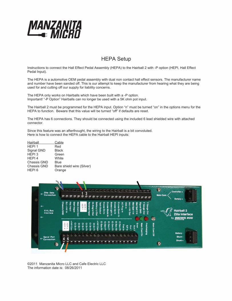
HEPI WiringIf your are using a Hall Effect Pedal Input, you will need a -P version of the Hairball and will need to wire it as described here. The pedal requires a 6 Pin shielded wire. Pin 1 on the HEPI is closest to the driver and number 6 is at the back. Signal Ground is connected to HEPI 2, Chassis Ground is connected to HEPI 5.HEPI 1,3,4 and 6 are connected as labeled on the Hairball and in the charts below.
Key and Start WiringThe key input informs the Hairball that you are about to start. It enables the battery light, check engine light, and turns on the motor contactors (if applicable). The start input initiates a precharge sequence, and upon successful completion of safety tests it turns on the main contactor and allows the controller to drive. This should take less than 3 seconds, usually much less. The start input needs only a momentary activation to start the controller. It is possible to tie the key and start wires together for those applications desiring only one switch to activate the vehicle. But beware, for it may compromise safety in some instances. Also, a separate key and start input can make diagnostics easier if there are problems with the wiring. The key input has to carry the current for the main contactor. For this reason it should be fused with a fuse rated to take the full coil current of the contactor. This value should usually be 4 amps or less.
Contactor WiringAll contactors driven through the Hairball must have 12V continuous rated coils. The main contactor is controlled by the Hairball for safety reasons, but the power to drive the contactor comes through the Key Input. Therefore any required safety shutdown circuit (such as those required for NHRA racing) can simply interrupt the power to the Key Input.
VERY IMPORTANT UPDATE! READ THIS!!!
The Hairball has internal contactor drivers which require snubber diodes on the contactor coils in order to absorb the inductive kick produced by the contactor coil when it turns off. Please note these may not be shown in the wiring diagrams.
The diodes which come with the Hairball package have no polarity, they can be connected in either direction across the coil connection on the contactors. These diodes have a 24V threshold so they are compatible with the fast turn off required for Kilovac contactors as well.
5

Sometimes it is desirable to have two contactors in series with the battery wiring. In this case one should be considered the safety contactor. It should be wired to turn on with or before the Key Input to the Hairball. The second contactor, which I will call the main contactor, should be wired through the Hairball as shown in the wiring diagrams. In this situation it is important that the Key and Start inputs are not tied together as one in order to avoid error codes on startup.
The Main contactor should only switch high voltage power to the controller. No other accessories should be connected downstream of the Main contactor. If one were to hook up a DC to DC, Heater, or other accessory in parallel with the controller, it would likely interfere with proper precharging and keep the controller from starting up.
Motor Contactors (-A, -S options)In applications that use motor contactors for either electric reverse or electric series parallel switching of the motors, the power for those contactor drivers needs to be supplied to both of the "+14V Cont" inputs. The power to these two together should be fused with one fuse to handle the coil current expected. With all options active, the maximum drive is 4 coils at once.
The Hairball monitors the motor contactors while driving and during switching. This assists safe switching and faster series/parallel switching. The contactor sense inputs "Ct Sen" always need to be connected for the options that are enabled in the Option menu. In cases where only one set of reversing contactors is being used, it is important to connect the F2 and R2 sense inputs to the F1 and F2 sense inputs respectively, so the Hairball will think they are all switching properly.
In some installation cases that do not use Series/Parallel switching of motors, such as in Sparrows, it is burdensome to add microswitches to the motor contactors for sensing. In that case it is possible to bypass the contact position sensing by joining the "Ct Dr R1" to both "Ct Sen R1" and "Ct Sen R2" and the same goes for the forward contactors. When doing this shortcut, the designer and user should be aware that switching the contactors under load can damage them. Also, switching these under high loads can damage the Zilla. Hairballs with the -S option have these connections made internally. For -S models none of the Ct Sen connections should be wired.
Never bypass the microswitch requirement for the Series/Parallel contactors, the consequences can be disastrous. When setting up Series Parallel contactors, it is good to test them before driving. Do this by turning on the key, turning off the autoshift option and using the "S/P In" to control them. Cycling them should not throw any errors and the contacts should switch together.
Fuse SelectionIt is important to have a fast semiconductor fuse in the battery circuit that feeds the controller. If there were to be some major problem with the Zilla or motor, a standard fuse or circuit breaker would not trip fast enough to protect the controller from excessive internal damage.
Failure to use an appropriate fuse can void the warranty on your controller, in addition to causing a variety of unsafe conditions.
Selecting the proper fuse can be a difficult process as it depends on what power the batteries can source, the capacity of the main contactor and other components, the system voltage, as well as what the controller settings are.The fuse should have a DC voltage rating higher than the maximum expected battery voltage. Since DC voltage ratings are often lower than the AC ratings, be sure to check the data sheet for the fuse you intend to use. A rule of thumb that I use is that the current rating for the fuse should be so that it can withstand full controller current for 20 seconds. It is also important to verify that the fuse withstand time curve is below that of the contactors and other components used in the circuit. In street vehicles where there is no desire for a high battery current, lower current rated fuses can be used so long as the battery current is set appropriately in the Hairball to keep them from blowing.
6

As a general guideline, I will offer a few recommendations here which will allow full power through the controller. Using fuses larger than these should only be done after careful study of the system. • A Z1K up to 300V should use a fuse like the Ferraz Shawmut #A30QS500 500A 300V fuse. • A Z2K up to 300V can use a fuse like the Ferraz Shawmut #A30QS800 800A 300V fuse. For systems that reach over 300V (about 276V nominal pack voltage) the A50QS series is a good choice.• The Ferraz Shawmut A50QS400-4 fuse is appropriate for most situations involving up to 348V of Exide Orbital batteries and a Z1K-EHV. • The Ferraz Shawmut A50QS600-4 fuse is appropriate for most situations involving up to 348V of Exide Orbital batteries and a Z2K-EHV.Systems running under 150V max. may be able to run a more economical fuse from the A15S series.
Speed SensorThe Hairball needs a speed sensor connected to the motor in order to do rev limit and stall detect, as well as to drive the tachometer. If these features are not desired or enabled, then the system will work without a sensor. The speed sensor is not included with the unit. The Hairball has been designed to use a four pulse per revolution sensor, such as the one that comes stock on Sparrow motors from Advanced DC. These speed sensor assemblies are available from Cafe Electric, or your authorized dealer. Any sensor which pulls the signal wire low four times per revolution with approximately a 50% duty cycle should work. I recommend hall effect units that use magnets as they are not as susceptible to dirt as the optical pickups are.
Speed sensors are especially susceptible to electrical noise and can benefit from a shielded twisted pair wire between them and the Hairball. We include 6 feet of this wire with every sensor that we provide. Some speed sensors still have problems, even with shielded twisted pair wiring. In those cases I find it helpful to filter the power to the speed sensor by putting a 0.1 microfarad capacitor on the power leads to the sensor. It is important that this capacitor is close to the sensor, within 8" is good.
AC Plug InThe AC Plug In connection is used to inhibit driving away with the charger plugged in. Sensing of a plugged in condition requires a switch to be active when the cord is plugged in. This switch should be connected to supply SLI power (12 V) the the AC Plug In pin on the Hairball when the car is plugged in. Using a relay from the AC line is a poor substitute for a switch since it will not function if the AC power were to be turned off by a tripped breaker or some such incident. If an attempt is made to drive off with this input active, the Hairball will not allow the main contactor to activate. Additionally it will slowly flash the Check Engine Light to indicate the problem. If it is desirable to reverse the polarity of the AC Plug In connection (so it is at 12V when it is safe to drive), this can be enabled by switching that option in the Options menu.
Controller Overheat IndicationThe check engine light has an addition function to indicate as a hot controller indication. This is yet another reason why you should connect this output to the light on your dash. If the controller exceeds the temperature cutback point the check engine light will repetatively emit a short flash. As the controller temperature gets hotter, the duration of the flash also gets longer.
Future FeaturesThe Hairball version 2 allows for a number of new features. Many of these, such as cruise control, have not yet been implemented. The connections for those have been labeled (future feature) in the charts below.
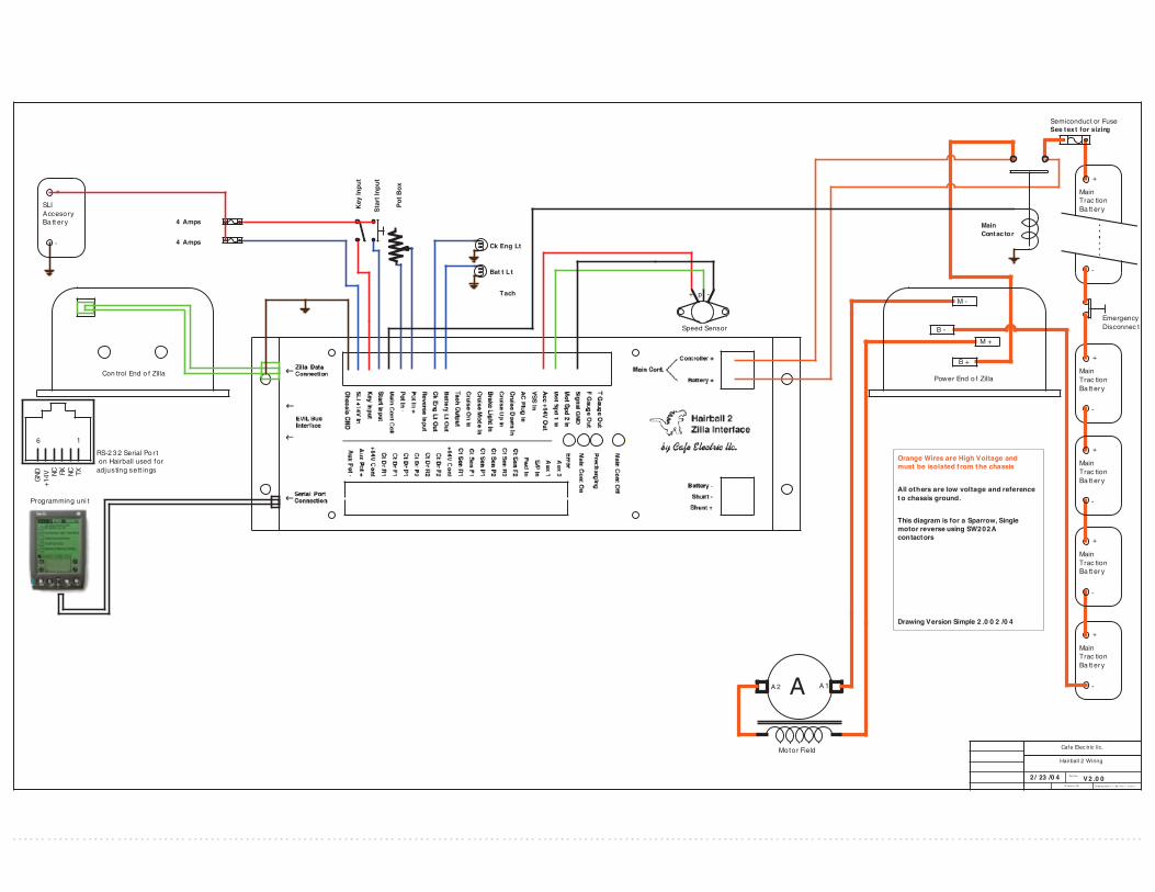
How to Hook up the Hairball and ZillaWiring diagrams are located at the end of this document. Use the Simple Diagram to get it running and see how little is actually required to hook it up. It shows the minimum connections required to get the system running. Actually, the dash lights, speed sensor and Palm terminal are not required for it to run, but they are recommended. Use the Sparrow Diagram to wire a single motor system with contactors for reversing motors such as what is used in a Sparrow.
7

Use the Full Diagram to hook everything up for a dual motor, direct drive system with electric reverse. This shows almost all the current options enabled and should be used as a reference for hooking up options. The Hairball 2 does not have pin numbers on the terminals. It has text descriptions instead. In the event that the text is worn off, the table below shows numbers starting with #1 at the top left near the Zilla Data Connection and progressing clockwise around the unit to #50 on the lower left near the serial port connection. Please be aware that many options require that you enable them in the Options menu in the Hairball. You will need to set up a data link of some sort as described below to do this.
Another very important noteHairballs are not protected from short circuits, you can avoid having to send them back fro repair by being very careful to only wire it with the power disconnected. Most common failures are around speed sensor, tachometer and dash light wiring getting shorted. Putting the SLI 14V In fuse in a easy to access place helps avoid the temptation to work on it with power on.
8
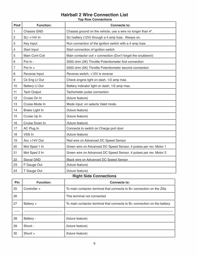
Hairball 2 Wire Connection List Top Row Connections
Pin# Function: Connects to:
1 Chassis GND Chassis ground on the vehicle, use a wire no longer than 4".
2 SLI +14V In SLI battery (12V) through a 4 amp fuse. Always on.
3 Key Input Run connection of the ignition switch with a 4 amp fuse.
4 Start Input Start connection of ignition switch
5 Main Cont Coil Main contactor coil + connection (Don"t forget the snubbers!)
6 Pot In - 5000 ohm (5K) Throttle Potentiometer first connection
7 Pot In + 5000 ohm (5K) Throttle Potentiometer second connection
8 Reverse Input Reverse switch, +12V is reverse
9 Ck Eng Lt Out Check engine light on dash, 1/2 amp max.
10 Battery Lt Out Battery indicator light on dash, 1/2 amp max.
11 Tach Output Tachometer pulse connection
12 Cruise On In (future feature)
13 Cruise Mode In Mode input: on selects Valet mode.
14 Brake Light In (future feature)
15 Cruise Up In (future feature)
16 Cruise Down In (future feature)
17 AC Plug In Connects to switch on Charge port door
18 VSS In (future feature)
19 Acc +14V Out Red wire on Advanced DC Speed Sensor
20 Mot Sped 1 In Green wire on Advanced DC Speed Sensor, 4 pulses per rev. Motor 1
21 Mot Sped 2 In Green wire on Advanced DC Speed Sensor, 4 pulses per rev. Motor 2
22 Signal GND Black wire on Advanced DC Speed Sensor
23 F Gauge Out (future feature)
24 T Gauge Out (future feature)
Right Side Connections
Pin Function: Connects to:
25 Controller + To main contactor terminal that connects to B+ connection on the Zilla
26 This terminal not connected
27 Battery + To main contactor terminal that connects to B+ connection on the battery
------
---
------------------------------------
----------------
---------------------------------------------------------------------------------------------------
-----------28 Battery - (future feature)
29 Shunt - (future feature)
30 Shunt + (future feature)
9

Bottom Row Connections (-A Option Only)
Pin Function: Connects to:
31 Aux 1 (future feature)
32 Aux 2 (future feature)
33 S/P In Series / Parallel Switch. Also activates other functions, see text.
34 Fwd In Forward Switch, + 12V is forward
35 Ct Sen F2 Motor 2 Forward Contactor Microswitch (Not used for -S)
36 Ct Sen R2 Motor 2 Reverse Contactor Microswitch (Not used for -S)
37 Ct Sen P2 Parallel 2 Contactor Microswitch (Not used for -S)
38 Ct Sen P1 Parallel 1 Contactor Microswitch (Not used for -S)
39 Ct Sen F1 Motor 1 Forward Contactor Microswitch (Not used for -S)
40 Ct Sen R1 Motor 1 Reverse Contactor Microswitch (Not used for -S)
41 +14V Cont +14V Input to drive motor contactors, connect both
42 Ct Dr F2 Motor 2 Forward Contactor + Connection (Not used for -S)
43 Ct Dr R2 Motor 2 Reverse Contactor + Connection (Not used for -S)
44 Ct Dr P2 Parallel 2 Contactor + Connection (Not used for -S)
45 Ct Dr P1 Parallel 1 Contactor + Connection (Not used for -S)
46 Ct Dr F1 Motor 1 Forward Contactor + Connection
47 Ct Dr R1 Motor 1 Reverse Contactor + Connection
48 +14V Cont +14V Input to drive motor contactors, connect both
49 Aux Pot + (future feature) Relabeled for HEPI Input
50 Aux Pot - (future feature) Relabeled for HEPI Input
Left End Connections: Serial Ports
Connector Function: Connects to:
6 Pin Data Serial Port
Connection#
Serial port of a Palm Pilot or other text terminal. Use black data cable
and adapter (included). Cable is wired Pin 1 to Pin 1.
RCA (2) EVIL Bus Interface Optional EVIL Bus Interface connections, (future feature)
8 Pin Data Zilla Data Connection Zilla Controller with Standard Cat 5 Cable included, Green. (pin 1 to pin
1)
10

Communicating with the Hairball: The Hairball has many adjustments and features. Many of which are systems which shut the controller down if a potentially unsafe situation arises. This necessitates some sort of communication between you and the Hairball in order to set the adjustments and find out why the controller has shut down if a safety situation arises. Diagnostic Trouble Codes (DTCs) are used to indicate and record why the controller has shut down. They can be read by using a shorting plug as described below, or with a serial terminal, which is much easier.
Diagnostic Trouble Codes (DTC) are four digit numbers ranging from 1111 to 4444. Codes below 1244 are errors and are stored for later review. Codes 1311 and above are used to indicate the current operating state. A table below lists what each code represents.
In order to set the adjustments, some sort of computer with a serial terminal program is required. A Palm Pilot is the recommended device for this operation, but almost any computer with a built-in serial terminal can be used. A serial terminal loaded in a Palm Pilot can also be used for reading and clearing DTCs. See setup information below.
Your controller came with a grey serial adaptor. There are two types, one for the Palm and one for other PCs. If you have the wrong one for the system that you want to use, you can adapt to the other system by using a “Null Modem” and “Gender Changer” both of which are available from Radio Shack.
Simple diagnostics, without the ability to adjust settings, can be performed by use of the included shorting plug. It triggers the Hairball to blink error codes on the check engine light. This can be useful if a problem is encountered and a serial terminal is not available. It is a good idea to keep the shorting plug and a copy of this manual in the car at all times.
Reading Diagnostic Trouble Codes Using the Check Engine LightIn order to read DTCs on the check engine light, first locate the orange serial port shorting plug that came with the Hairball. This is a 6-pin telephone style plug with a single loop of orange wire shorting two pins. This plug, when plugged in, will short the RX pin to +14V. Be sure not to confuse it with the similar shorting plug that comes with some Todd chargers, that one has black wire.
Codes will be blinked out on the check engine light on the Hairball. Four sets of blinks per code, with pauses in between digits. The definitions of DTCs are located near the end of this manual.
To Read DTCs1) Turn the key switch on. (It is not necessary to turn it to "Start.")2) Insert the shorting plug for 4 seconds and then remove it.3) The Hairball will now blink the current Operating Status code and stop.4) Insert the shorting plug and remove it again to view the newest stored error code. 5) Repeat step 4 to view older error codes, up to 5 can be stored.6) The last code will be followed by a code of 1111. 7) Turn the key off after reading any number of codes to reset the reading procedure.
To Clear DTC History1) Insure that the key switch is off. 2) Insert the shorting plug for 20 seconds and then remove it.3) The Hairball will blink a 1111 code to indicate it has cleared the DTC memory.
11
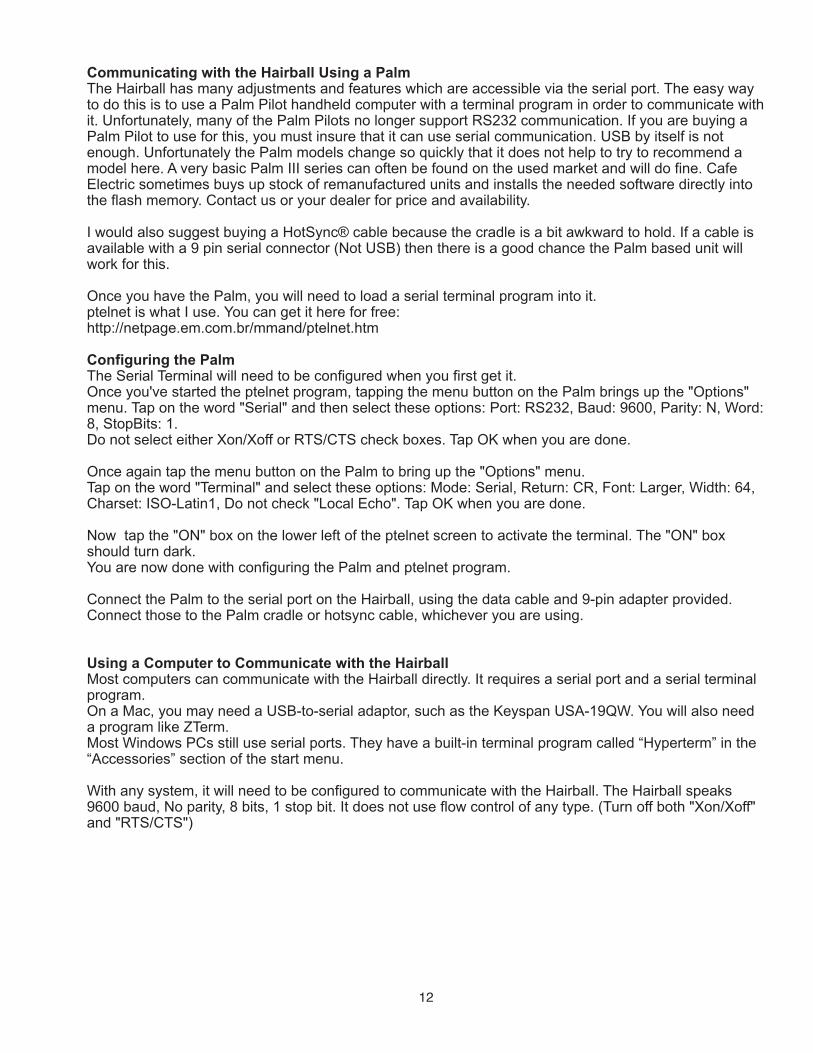
Communicating with the Hairball Using a PalmThe Hairball has many adjustments and features which are accessible via the serial port. The easy way to do this is to use a Palm Pilot handheld computer with a terminal program in order to communicate with it. Unfortunately, many of the Palm Pilots no longer support RS232 communication. If you are buying a Palm Pilot to use for this, you must insure that it can use serial communication. USB by itself is not enough. Unfortunately the Palm models change so quickly that it does not help to try to recommend a model here. A very basic Palm III series can often be found on the used market and will do fine. Cafe Electric sometimes buys up stock of remanufactured units and installs the needed software directly into the flash memory. Contact us or your dealer for price and availability.
I would also suggest buying a HotSync® cable because the cradle is a bit awkward to hold. If a cable is available with a 9 pin serial connector (Not USB) then there is a good chance the Palm based unit will work for this.
Once you have the Palm, you will need to load a serial terminal program into it.ptelnet is what I use. You can get it here for free: http://netpage.em.com.br/mmand/ptelnet.htm
Configuring the PalmThe Serial Terminal will need to be configured when you first get it.Once you've started the ptelnet program, tapping the menu button on the Palm brings up the "Options" menu. Tap on the word "Serial" and then select these options: Port: RS232, Baud: 9600, Parity: N, Word: 8, StopBits: 1. Do not select either Xon/Xoff or RTS/CTS check boxes. Tap OK when you are done.
Once again tap the menu button on the Palm to bring up the "Options" menu. Tap on the word "Terminal" and select these options: Mode: Serial, Return: CR, Font: Larger, Width: 64, Charset: ISO-Latin1, Do not check "Local Echo". Tap OK when you are done.
Now tap the "ON" box on the lower left of the ptelnet screen to activate the terminal. The "ON" box should turn dark.You are now done with configuring the Palm and ptelnet program.
Connect the Palm to the serial port on the Hairball, using the data cable and 9-pin adapter provided. Connect those to the Palm cradle or hotsync cable, whichever you are using.
Using a Computer to Communicate with the HairballMost computers can communicate with the Hairball directly. It requires a serial port and a serial terminal program. On a Mac, you may need a USB-to-serial adaptor, such as the Keyspan USA-19QW. You will also need a program like ZTerm.Most Windows PCs still use serial ports. They have a built-in terminal program called “Hyperterm” in the “Accessories” section of the start menu.
With any system, it will need to be configured to communicate with the Hairball. The Hairball speaks 9600 baud, No parity, 8 bits, 1 stop bit. It does not use flow control of any type. (Turn off both "Xon/Xoff" and "RTS/CTS")
12

Using the Serial TerminalThe Hairball requires a minimum of Chassis GND and SLI +14V In battery power in order to communicate. It may not communicate when the throttle pot is depressed. Commands are case sensitive, therefore "d" is not the same as "D."
Main MenuThe Esc button is your friend. It gets you out of most any operation and also returns you to the main menu. Press it to see the main menu. It will look like this:
d) Display settings
b) Battery Menu
m) Motor Menu
s) Speed Menu
o) Options Menu
p) Special Menu
Esc) Cancel
State: 1311
How may I help you?
The menus have letters in front of the selections and abbreviated labels. To changea value, just enter the letter of the selection and follow the prompts. Numericalvalues are often saved slightly different than what was entered. This is because the Hairballadjusts them to the nearest value that it can use. If the Hairball does not understand your input,it will reply with: Huh? Values will not be saved if the SLI voltage is too low.
DisplayThe settings listed in this example are those that I run in a 240V Porsche. The display menu looks like this:
! Display only, change with menu
! a)BA, v)LBV, i)LBVI
! 1800 119 145
! a) Amp, v) Volt, i) RA
! 1600 429 700
! r) RV, c) PA, p) PV
! 106 2000 180
! l)Norm, r)Rev, x)Max
! 7000 1500 8000
! a) On b) On c) On d) On
! e) Off f) On g) On h) On
! i) Off j) Off k) Off l) Off
! m) Off n) Off o) Off p) Off
! Errors, Old-New:
! 1111 1111 1111 1111 1111
! State: 1311 Return for menu
Due to a lack of space, the labels are abbreviated in the menus. I will go over them here, onemenu at a time.
13
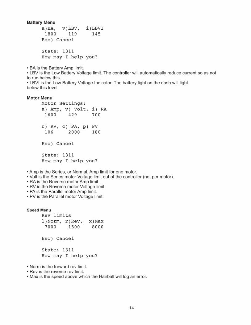
Battery Menu
! a)BA, v)LBV, i)LBVI
! 1800 119 145
! Esc) Cancel
!
! State: 1311
! How may I help you?
• BA is the Battery Amp limit. • LBV is the Low Battery Voltage limit. The controller will automatically reduce current so as notto run below this. • LBVI is the Low Battery Voltage Indicator. The battery light on the dash will lightbelow this level.
Motor Menu
! Motor Settings:
! a) Amp, v) Volt, i) RA
! 1600 429 700
!
! r) RV, c) PA, p) PV
! 106 2000 180
!
! Esc) Cancel
!
! State: 1311
! How may I help you?
• Amp is the Series, or Normal, Amp limit for one motor.• Volt is the Series motor Voltage limit out of the controller (not per motor).• RA is the Reverse motor Amp limit.• RV is the Reverse motor Voltage limit• PA is the Parallel motor Amp limit.• PV is the Parallel motor Voltage limit.
Speed Menu
! Rev limits
! l)Norm, r)Rev, x)Max
! 7000 1500 8000
!
! Esc) Cancel
!
! State: 1311
! How may I help you?
• Norm is the forward rev limit.• Rev is the reverse rev limit.• Max is the speed above which the Hairball will log an error.
14

A Word about Valet Mode
When power (12V) is applied to the "Cruise Mode In" input, the Valet mode is active. When engaged, this activates a second set of settings. These settings can be used for a variety of things, such as Economy Mode, race adjustments or Teenager Mode. The input must be engaged in order to display or change the Valet settings.
Settings that change when Valet is engaged:Battery Amps, Low Battery Volts, Low Battery Voltage IndicatorMotor Amps and Volts in Series, Parallel and ReverseNormal and Reverse Speed Limits
Note: Max Speed and Options are not changed in Valet mode.
How to Tell if You Are in Valet ModeHave a look at the State display at the bottom of the display, press Esc to refresh it.
It will look something like this:
Valet Mode Active: Valet Mode Not Active:
State: 1311 Valet, !! State: 1311
How may I help you? ! ! How may I help you?
Options Menu
Options: Enter letter to change
a) On b) On c) On d) On
e) Off f) On g) On h) On
i) Off j) Off k) Off l) Off
m) Off n) Off o) Off p) Off
Esc) Cancel
State: 1311
How may I help you?
This menu consists of flags which adjust what options are enabled in the Hairball.Flags can be either on or off. Writing the letter of the option will toggle it on or off. Always check the confirmation to insure that the changes are what you expected.This table lists the names of the various flags.
15

Flags: a) MotSpd1 b) MotSpd2 c) AutoShift d) StallDetect e) Batt lt polarity f) Ck eng lt pol g) FR Contactors h) SP Contatctors i) Parallel Reverse j) Drag Race k) Amps on Tach l) 6 Cyl Tach m) Plug in Polarity n) HEPI o) p)Z1K Scaling
• Flags "a" and "b" should be on if those motor speed sensors are connected. Motor speed sensors should produce four pulses per revolution. Motor speed is used for Stall Detect and Rev Limit functions, as well as inhibiting changing power direction while moving over a minimum speed. • Flag "c" on enables auto shifting from series to parallel of two motor systems. This is set up to automatically shift from series to parallel any time these conditions are met: Full throttle requested, No current limits active, Average motor current is less than half of the available current from the controller. It shifts back to series when the duty cycle is below 50% for 3 seconds. If this flag is not set, then shifting is controlled manually through the S/P In pin.• Flag "d" on enables a Stall Detect. This will cut power if current is flowing for too long without the motor turning. The stall cutout time is shorter if higher currents are flowing and longer at lower currents. It varies from about 0.5 seconds at high current to 12 seconds at 50 amps. If the stall detect has tripped, it can be reset by lifting and reapplying the accelerator pedal. • Flags "e" and "f" change the output polarity of the indicator light drivers. Some dashboards require this.• Flags "g" and "h" configure the Hairball to be wired with Reversing and Series/Parallel contactors respectively. • Flag "i" forces unit to stay in parallel when "h" is on and vehicle is in reverse. In some systems this can help traction. • Flag "j" inhibits any shifting when "c" is on and the Series/Parallel (h) input is on and the “S/P In” input is on. This is useful to inhibit shifting during a burnout.• Flag "k" makes the tachometer display motor amps multiplied by ten instead of motor RPM. • Flag "l" changes the tachometer output from 4 to 6 cylinders when it is on. • Flag "m" reverses the polarity of the Plug In Input. • Flag "n" activates the HEPI input. This must only be on if the Hairball is a -P model. • Flag "o" is not used yet.• Flag "p" sets the amp display scaling to fit the Z1K instead of the Z2K. Turn this off for Z2Ks.
If the Hairball is equipped with Option -A (contactor drivers) but you are not using the Series / Parallel switch, then it is possible to use this input to select motor amps display on tach instead of RPM on the fly. To activate it, you must have Option "c" on and "j" and "k" off.
Special Menu
Special Menu: W) Resetc) Clear Error p) PrechargeQ) DAQ <1-4> D) DefaultsErrors, Old-New:1111 1111 1111 1111 1111Error Count: 0Esc) Cancel
State: 1311How may I help you?
Reset: "W" resets the Hairball, this is for testing, reloading code, and handy for reading the software version number. Clear Error: "c" clears the DTC error history.Precharge: "p" manually turns on the precharger for the controller. This is only for testing.DAQ: "Q" is data acquisition. This is how various data can be viewed in real time. Details on this function are below. Defaults: "D" resets all the values back to factory default values. Below that is a listing of any stored errors.
16

Data Acquisition (DAQ)This is an advanced feature that most people won't need. If you like tinkering and understand it, you may like it.
Start the DAQ in the Special menu by typing "Q1" or "Q2" etc., followed by a return.DAQ data is displayed 10 lines per second in Hex format with spaces between data. Data is approximate and the scaling values vary.Press the space bar to exit DAQ mode. DAQs may change with new code versions, please check the latest update notes. This list is for HB code version 2.12.
DAQ 1, Data from the Zilla but in a different order:
RxCtrlFlag.byte // controller mode.
ArmatureCurrent // Averaged current on the motor
ZCurrentLimit // Available current from the Zilla
ArmDC // Averaged Duty Cycle
BatteryVoltage // in voltoids
MotorVoltage // in voltoids
HeatSinkTemp // in tempoids.
SpiErrorCount
CurrentError
OperatingStatus
DAQ 2, Data To the Zilla but in a different order:
TxCtrlFlag.byte // mode requested.
ArmDCTarget
AccelTaskTime
ArmatureCurrentLimt // in ampoids
BatteryCurrentLimit // in ampoids
BatteryVoltageLimit // in voltoids
MotorVoltageLimit // in voltoids
EnableCount
OperatingStatus
DAQ 3:
DrivePot
DrivePot2 (HEPI) added on V2.06 and later
Speed1
Speed2
SLI Voltage
EEProm.UserMotorLimit
EEProm.UserBatteryLimit
ShiftRecCurrentLimit // not used.
CurrentError
OperatingStatus
DAQ 4:
DrivePot
Speed1
ArmatureCurrent
ZCurrentLimit
ArmDC
BatteryVoltage
MotorVoltage
HeatSinkTemp
OperatingStatus
After the DAQ data there will be a number of letters indicating states:S = Stopped stateG = Shifting in progressO = Main Contactor is on OKM = Motor contactors are on OKR = Direction is ReverseF = Direction is ForwardP = Motors are in ParallelS = Motors are in SeriesV = Main contactor has voltage drop (>5V) across power terminals.
17

Diagnostic Trouble CodesThe 2-digit number is what is displayed in the DAQ as OperatingStatus and CurrentErrorThe 4-digit code after it represents the DTC as displayed in other menus and blinked on the check engine light. For most uses it is best to ignore the 2 digit codes listed below.
Keep this page in the car with the shorting plug00 1111 Unknown mode, no error01 1112 Hairball watchdog reset02 1113 Hairball EEPROM CRC error03 1114 Controller watchdog reset04 1121 Controller EEPROM CRC error05 1122 Controller Desat error06 1123 Power section failed test07 1124 Main Contactor Stuck On08 1131 Shorted/Loaded Controller during precharge09 1132 Controller did not communicate during precharge0A 1133 Lost Communication with controller during use, either direction0B 1134 Lost Communication to controller, still receiving from controller0C 1141 Main Contactor High Resistance0D 1142 Controller still not off... Main contactor trying to turn off0E 1143 Motor Contactor State Machine got an illegal Value, Software error0F 1144 Motor Contactors no longer matched requested state10 1211 Controller still not off...Motor contactors trying to turn off11 1212 Motor Contactors did not turn off12 1213 Motor Contactors did not turn on13 1214 Open Pot Wire14 1221 Major Overspeed Either Motor Beyond redline by X,15 1222 Unused. 16 1223 SLI battery below warning threshold17 1224 SLI battery too low and caused shutdown of controller.18 1231 Propulsion pack open, no contactor drop, and controller is not responding19 1232 This should never happen, contact the factory if it does1A 1233 Hall Effect Pedal Input invalid1B 1234 Motor voltage is high on startup1C 1241 Key input not on while start is asserted
In addition to the above errors, the OperatingStatus is represented by these non-fault states:20 1311 waiting for key21 1312 waiting for start signal22 1313 waiting for zero pot23 1314 wait for throttle input24 1321 wait for go button, drag race mode only, *Install later*25 1322 direction selected is not allowed (rolling too fast or inactive state)26 1323 battery voltage limit active27 1324 motor current limit active28 1331 battery current limit active29 1332 temperature current limit active2A 1333 SPI packet error in controller 2B 1334 Zilla waiting for enable signal30 1411 Normal driving33 1414 Waiting for the vehicle to be unplugged
Reminder for checking codes with orange wire plug: Key on, plug for 4 seconds and remove, leave key on and repeat for more codes. 1111 is end of list.
Clear codes: Key off, plug for 20 seconds and remove, 1111 confirms that it has cleared codes.
(Hint: keep a copy of this page with the orange wire plug in your car)
18

CAFE ELECTRIC LLC. 12 MONTH LIMITED WARRANTY
CAFE ELECTRIC LLC. (the Company) warrants to the original retail purchaser of this product that should this product or any part thereof, under normal use and conditions, be proven defective in materials or workmanship within 12 months from the date of original purchase, such defect(s) will be repaired or replaced with new or reconditioned product (at the Company's option) without charge for parts or repair labor.
To obtain repair or replacement within the terms of this Warranty, the product is to be delivered with proof of warranty coverage (e.g., dated bill of sale), specification of defect(s), transportation prepaid, to the Company at the address shown below.
This Warranty does not extend to the costs incurred for installation, removal or reinstallation of the product, nor to any damage to the vehicle including its motor, drivetrain or electrical systems.
This Warranty does not apply to any product or part thereof which, in the opinion of the Company, has suffered or been damaged through alteration, improper installation, failure to install in accordance with the Installation Manual(s), mishandling, neglect, accident, misuse, specifically including, but not limited to: improper fusing, disassembly in any way, exposure to moisture and extreme uncontrolled currents caused by excessive motor voltage, which is also known as fireballing. THE EXTENT OF THE COMPANY'S LIABILITY UNDER THIS WARRANTY IS LIMITED TO THE REPAIR AND/OR REPLACEMENT PROVIDED ABOVE AND, IN NO EVENT, SHALL THE COMPANY'S LIABILITY EXCEED THE PURCHASE PRICE PAID BY THE PURCHASER FOR THE PRODUCT.
This Warranty is in lieu of all other express warranties or liabilities. ANY IMPLIED WARRANTIES, INCLUDING ANY IMPLIED WARRANTY OF MERCHANTABILITY, SHALL BE LIMITED TO THE DURATION OF THIS WRITTEN WARRANTY, ANY ACTION FOR BREACH OF ANY WARRANTY HEREUNDER INCLUDING ANY IMPLIED WARRANTY OF MERCHANTABILITY MUST BE BROUGHT WITHIN A PERIOD OF 30 MONTHS FROM DATE OF ORIGINAL PURCHASE. IN NO CASE SHALL THE COMPANY BE LIABLE FOR ANY CONSEQUENTIAL OR INCIDENTAL DAMAGES FOR BREACH OF THIS OR ANY OTHER WARRANTY, EXPRESS OR IMPLIED, WHATSOEVER. No person or representative is authorized to assume for the Company any liability other than expressed herein in connection with the sale of this product.
Some states do not allow limitations on how long an implied warranty lasts or the exclusion or limitation of incidental or consequential damage, so the above limitations or exclusions may not apply to you. This Warranty gives you specific legal rights and you may also have other rights which vary from state to state.
Cafe Electric llc does not allow its products to be transported into or through the Peoples Republic of China.
http://[email protected] but remove the number 2 from the address. It’s there for spam
control.
19

FAQFrequently Asked Questions
1) Q: Where is the FAQ? A: It’s getting so big that it needs a web page of its own. Look for it at:
http://CafeElectric.com/faq
2) Q: Why are there errors in the drawings? A: Because we’re still working on them. Known errors: a) All contactors must have snubber diodes connected before powering up the system! b) Sparrow drawing shows only diagram for Albright contactors and not the wiring for a -S option Sparrow with Kilovac Contactors. The -S option does not use the contactor sense inputs at all, and only the first two drive outputs. c) Simple drawing is labeled Sparrow. d) Drawings are missing all the recent options such as “Valet”, “AC Plug In” and “HEPI”. HEPI models come with a separate sheet describing the wiring of the pedal.
Last) Q: Where can I get answers to more questions? What if I don’t have web access?
A: Contact the dealer through which you bought the Zilla.
If you bought it direct from Cafe Electric, or if it’s a really tough question e-mail us at [email protected]. (but remove the number 2 from the address, that’s only for spam prevention since this manual is on the web)
20
Programming uni t
GN
D NC
NC
RS-2 3 2 Serial Po r t
on Hairball used for
adjusting sett ings
6 1
TXRX
+14V
SLI
Accesory
Ba tt ery
+
-
Main
Trac tion
Ba tt ery
-
+
A 2 A A 1
Motor Field
+
Semiconduct or FuseSee text for sizing
Emergency
Disconnec t
Main
Trac tion
Ba tt ery
-
+
-
Main
Trac tion
Ba tt ery
-
+
Power End o f Zilla
Orange Wires are High Voltage and
must be isolated f rom t he chassis
Main
Contac tor
Drawing Version Simple 2 .0 0 2 /0 4
This diagram is for a Sparrow, Single
motor reverse using SW202A
contactors
Tach
Ck Eng Lt
Bat t L t
Con trol End o f Zilla
4 Amps
4 Amps
Main
Trac tion
Ba tt ery
-
+
All others are low voltage and reference
t o chassis ground.
M +
B +
B -
M -
Main
Trac tion
Ba tt erySta
rt I
np
ut
Po
t B
ox
Key I
np
ut
Speed Sensor
+ p -
2 / 23 /0 4
Hairball 2 Wiring
V2 .0 0
Cafe Elec tric llc.
Par t No .
Dr aw n b y OE Dr aw ing Siz e 1 :1 . 99 1 f or 1 : 1 p rin t

Speed Sensor
+ p -
Key I
np
ut
Po
t B
ox
Sta
rt I
np
ut
Revers
e I
np
ut
SLI
Accesory
Ba tt ery
+
-
GN
D NC
NC
RS-2 3 2 Serial Po r t
on Hairball used for
adjusting sett ings
6 1
TXRX
+14V
A 1
S2
F
Motor FieldS1
A 2 A
Programming uni t
4 Amps
1 5 Amps
4 Amps
Con trol End o f Zilla
FR PP R
Bat t Lt
Ck Eng Lt
Tach
Speed Sensor
+ p -
Main
Trac tion
Ba tt ery
M +
B +
B -
M -
All others are low voltage and reference
t o chassis ground.
This diagram is for a Dual Motor setup,
where both motors reverse, with series
/ parallel switching of the motors and all
opt ions implemented.
Drawing Version DMSP 2 .0 0 2 /0 4
S2
Motor FieldS1
A 2 A A 1
Main
Contac tor
Orange Wires are High Voltage and
must be isolated f rom t he chassis
Power End o f Zilla
Main
Trac tion
Ba tt ery
-
+
Main
Trac tion
Ba tt ery
-
+
Main
Trac tion
Ba tt ery
-
+
-
Main
Trac tion
Ba tt ery
-
+
Emergency
Disconnec t
Fo
rward
In
pu
t
Semiconduct or FuseSee text for sizing
+
Dr aw ing Siz e 1 :1 . 99 1 f or 1 : 1 p rin tDr aw n b y OE
Par t No .
Cafe Elec tric llc.
V2 .0 1
Hairball 2 Wiring
2 / 23 /0 4
��������
�� ������� ����������������������������������� �������������������������������������������������������������������������� �
!��������� ����������"��#�$������� ��������������������������������������� �� �� �!�������������������������������"������� ��������� �!�� �� ��������������%�����������������������������&�������������������&� ����������������&�������� ������������������������ �
!����������������% ������������ ���������"��������������������������� ���������'�(���#����)��������� �����������&������ ����������*+����������� �
!��������������� �������&����������������������� �#�����(�)�� �����������(��)������������� ���������������������������� ��,�������������� �"������������������(���)���������� ������� �� ��
!���������� �-����������� �!���� ������������������ ��&�������������-������ ������������������������������������ �
��������� ���������� ������������&�������������&������������������ ����������"����� ������� ������������������������������������������������������� .
��������� �������������������� �/����� ������0� 1����&����234� ,���%�����5� 2���������6� 7�����/�� � �234 ,��/�� � �234 ,���� ���������������"��������-� #���&�
8�900��$��:������$�����;;/�����/�������������;;/!��������������������� .��9<=�-=�900������