owner's manual multitech 8 rev6...(document 2009-01-20 rev 6) owner’s manual multitech 8 read...
TRANSCRIPT

(Document 2009-01-20 Rev 6)
Owner’s Manual
Multitech 8
Read this entire booklet carefully before using the bed and its accessories.
These illustrations are for information purposes only.
TECHNICAL ASSISTANCE AND PARTS
(450) 783-6444 (450) 783-6446
[email protected] 125, rue de l’Église, Baie-du-Febvre, Qc, J0G 1A0
2
Preface
This manual contains all necessary indications to use the Rotec International
Multitech 8 medical bed safely. It has to be accessible at all times for the medical and
maintenance staff. In addition, this manual must stay with the bed when it is sold or
transferred.
Rotec International manufactures reliable beds. An appropriate use and a regular
maintenance are indispensable to maintain this reliability. The users and the personnel’s
security depend on it.
It is imperative that every person in charge acknowledges this manual in order to
train the staff properly before using this bed and its accessories. This will prevent any
potential injuries to the user or the personnel.
This bed meets the following security standards: CAN/CSA C22.2 No. 0 M91,
CAN/CSA C22.2 No. 601.1 M90, CAN/CSA C22.2 No. 601.1S1 94, C22.2 No. 601.1
M90, CAN/CSA C22.2 No. 601.1 Amendment 2, CAN/CSA C22.2 No. 60601-2-38-03,
UL Standard No. 60601-1.
Our policy on products and services Manufacturing adjustable beds has been Rotec International’s passion since 1985.
The company’s vision has allowed it to become an enterprise with a reputation that is the
envy of both residential and medical industries. The company’s mission is to provide a
superior quality range of safe and comfortable adjustable beds.
Anticipating tomorrow’s markets, the members of Rotec International’s team are
proud to contribute to the company’s success. Our multidisciplinary team constantly
strives to reach and maintain a high level of excellence.
Over the years, this passion has been the foundation of our expertise. Rotec
International is now proud to share its success with you…

3
Table of contents
1. TECHNICAL SPECIFICATIONS ............................................................................. 4
1.1 Safe working load ..................................................................................................... 4 1.2 Bed weight ................................................................................................................ 4 1.3 Accessories ............................................................................................................... 4 1.4 Electrical specifications ............................................................................................ 4 1.5 Storage ...................................................................................................................... 4 1.6 Moving specifications ............................................................................................... 5 1.7 Measurement specifications...................................................................................... 5 1.8 Limited warranty....................................................................................................... 6 1.9 Return policy............................................................................................................. 7
1.9.1 Non compliant product ...................................................................................... 7 1.9.2 Damaged product ............................................................................................... 7 1.9.3 Returned product................................................................................................ 7
2. ACCESSORIES INSTALLATION INSTRUCTIONS ............................................. 8
2.1 Wooden (or composite) head and foot boards installation ....................................... 9 2.2 Trapeze bar installation (optional) .......................................................................... 10
3. USER INSTRUCTIONS ............................................................................................ 11
3.1 Precautions .............................................................................................................. 11 3.2 Verifications before starting to use the bed ............................................................ 13 3.3 Using the functions of the bed ................................................................................ 14
3.3.1 Remote control of the bed................................................................................ 14 3.3.2 Nurse control (optional) ................................................................................... 15
3.4 Trendelenburg and reverse Trendelenburg ............................................................. 16 3.5 Adjusting the angle of the foot section ................................................................... 17 3.6 Hooks for draining bags.......................................................................................... 18 3.7 Openings for restraining straps ............................................................................... 18 3.8 I.V. pole holders...................................................................................................... 18 3.9 Using the accessories .............................................................................................. 19
3.9.1 Side rails........................................................................................................... 19 3.9.2 Casters with synchronized brake system ......................................................... 19 3.9.3 CPR (optional) ................................................................................................. 20
3.10 Inspection.............................................................................................................. 20 3.11 Special recommendations ..................................................................................... 21
4
1. TECHNICAL SPECIFICATIONS
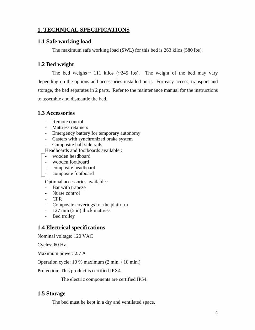
1.1 Safe working load The maximum safe working load (SWL) for this bed is 263 kilos (580 lbs).
1.2 Bed weight The bed weighs ~ 111 kilos (~245 lbs). The weight of the bed may vary
depending on the options and accessories installed on it. For easy access, transport and
storage, the bed separates in 2 parts. Refer to the maintenance manual for the instructions
to assemble and dismantle the bed.
1.3 Accessories - Remote control - Mattress retainers - Emergency battery for temporary autonomy - Casters with synchronized brake system - Composite half side rails Headboards and footboards available : - wooden headboard - wooden footboard - composite headboard - composite footboard
Optional accessories available : - Bar with trapeze - Nurse control - CPR - Composite coverings for the platform - 127 mm (5 in) thick mattress - Bed trolley
1.4 Electrical specifications Nominal voltage: 120 VAC
Cycles: 60 Hz
Maximum power: 2.7 A
Operation cycle: 10 % maximum (2 min. / 18 min.)
Protection: This product is certified IPX4.
The electric components are certified IP54.
1.5 Storage The bed must be kept in a dry and ventilated space.

5
1.6 Moving specifications Before moving the bed, it must be at the lowest position and you need to wind the
power cable around the hooks situated at the head of the bed (see p.8: power cable
support). Always use the headboard or the footboard of the bed to move it. Make sure it
is properly fixed before proceeding. Never use the side rails to move the bed.
Always manipulate the bed carefully. Apply the brakes when the bed is in place.
1.7 Measurement specifications
1 Overall length (A) : 2260 mm (89 in)
Overall height (B) : 2311 mm (91 in)
(With trapeze bar and the bed at its highest position)
2 Overall width: - Half side rails (C) : 1041 mm (41 in)
3 Height of bed without mattress: - Lower position (D) : 216 mm (8 1/2 in)
- Highest position (E) : 749 mm (29 1/2 in)
4 Distance between the head and the tip of the trapeze bar (F) : 995 mm (39 3/16 in)
C C
E
A
B
D
F C

6
5 Maximum angles - Head ~68 degrees
- Thighs ~34 degrees
- Head – Thighs ~95 degrees
* The dimensions specified in this manual do not take the manufacturing tolerances into
consideration.
1.8 Limited warranty Rotec International manufactures reliable beds. Our products are guaranteed
against manufacturing defects up to one year after the bed is bought. Furthermore, we
offer a specific 20-year guarantee on the frame, 2-years on the electric motors, hand
control and electronic components following the date of purchase.
Rotec International reserves the right to substitute equal or superior quality
materials during repairs and/or replacements. The material replaced and covered by this
warranty does not allow one to benefit from a new warranty. It only benefits from the
original warranty. For further information, contact our technical services.
This warranty does not cover damages caused by negligence or inappropriate use.
Rotec International will not be held responsible for any other warranty offered by any
person, firm or company, to the exclusion of the one stipulated above.
This warranty gives you specific legal use rights and is only valid for the original
purchaser or for anyone who would have received it as a gift.
34°
68° 95°

7
1.9 Return policy 1.9.1 Non compliant product
If a Rotec International product is not according to the original order invoice, the
problem must be notified within 48 hours after the time of delivery. Actions necessary to
correct the situation will be at Rotec International’s expense and will be made as soon as
possible, following the notification of the non compliancy.
1.9.2 Damaged product It is the responsibility of the receiver to verify the shipment even if the box(es)
seems to be in good condition. If there is any damage, it must be indicated on the bill
of lading. Rotec International must be informed of the situation within 24 hours of
receipt of goods in order to notify the carrier as soon as possible. If Rotec International is
not informed within 24 hours or the damages are not indicated on the bill of lading, the
customer may have to pay all the costs incurred to replace or repair the damaged product.
1.9.3 Returned product Returned goods require a RGA number and are subject to a 25% restocking fee.
Furthermore, the customer must pay the transport charges. For more information, please
contact our customer service.

8
2. ACCESSORIES INSTALLATION INSTRUCTIONS
Headboard (composite
model shown)
Footboard (wood model shown)
Example of half side rails
Trapeze bar (optional)
Nurse control (optional)
Openings for restraining straps (12)
Head section
Thighs sectionLower
back section
Foot section
Power cable support
Openings for restraining straps (8) (or draining bags)
Composite coverings (optional)
Wall bumper

9
2.1 Wooden (or composite) head and foot boards installation Gently slide the two (2) bars, of the head and foot boards, into the anchorage, to
the bottom;
To remove the head or the foot boards, lift the head or foot boards.
2 bars
10
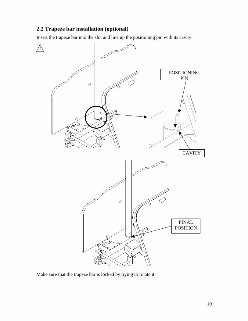
2.2 Trapeze bar installation (optional) Insert the trapeze bar into the slot and line up the positioning pin with its cavity.
Make sure that the trapeze bar is locked by trying to rotate it.
CAVITY
POSITIONING PIN
!
FINAL POSITION
11
3. USER INSTRUCTIONS
3.1 Precautions Do not use this bed and its accessories without reading carefully this manual and
acknowledging all of the following precautions:
This bed is not for pediatric use;
This bed should not be used in presence of flammable anesthetic gas mixed with air,
oxygen or nitrogen oxide;
Always apply the brakes after moving the bed and before a person sits or lays down
in the bed. This procedure is important in order to reduce the risk of injuries when
the user is getting in or out of the bed. Try to move the bed to make sure that the
brakes are applied;
Take into consideration the general condition of the user before automatically raising
the half side rails at the foot end of the bed so that the user can get out of the bed at
their convenience;
Unless otherwise medically advised by a professional, leave side rails up and locked
when the user is sleeping or left without supervision;
When the side rails are up, try to move them to make sure that they are properly
locked;
Side rails are made to prevent accidental falls. They must not be used to restrain, to
keep the user from getting out of the bed or to help the user to turn. It is the staff’s
responsibility to use the appropriate restraining means, for the user’s safety;
Always lower the bed when the user is sleeping or left without supervision to reduce
risks of falls or injuries;
Always make sure that nothing interferes with the functioning of the bed before using
the commands, i.e.: user or staff’s limbs, medical equipment, etc… which could
result in injuries and/or equipment failure;
Make sure that the power cable is properly fixed so it cannot be damaged during the
functioning of the bed and to avoid injuries and/or equipment failure;
Unless otherwise proscribed by a medical professional, always place the platform
horizontally when the user is sleeping;
!
12
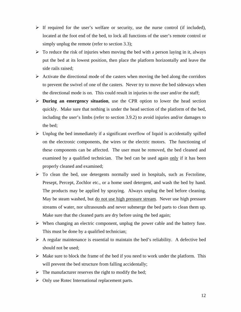
If required for the user’s welfare or security, use the nurse control (if included),
located at the foot end of the bed, to lock all functions of the user’s remote control or
simply unplug the remote (refer to section 3.3);
To reduce the risk of injuries when moving the bed with a person laying in it, always
put the bed at its lowest position, then place the platform horizontally and leave the
side rails raised;
Activate the directional mode of the casters when moving the bed along the corridors
to prevent the swivel of one of the casters. Never try to move the bed sideways when
the directional mode is on. This could result in injuries to the user and/or the staff;
During an emergency situation, use the CPR option to lower the head section
quickly. Make sure that nothing is under the head section of the platform of the bed,
including the user’s limbs (refer to section 3.9.2) to avoid injuries and/or damages to
the bed;
Unplug the bed immediately if a significant overflow of liquid is accidentally spilled
on the electronic components, the wires or the electric motors. The functioning of
these components can be affected. The user must be removed, the bed cleaned and
examined by a qualified technician. The bed can be used again only if it has been
properly cleaned and examined;
To clean the bed, use detergents normally used in hospitals, such as Fectolime,
Presept, Percept, Zochlor etc., or a home used detergent, and wash the bed by hand.
The products may be applied by spraying. Always unplug the bed before cleaning.
May be steam washed, but do not use high pressure stream. Never use high pressure
streams of water, nor ultrasounds and never submerge the bed parts to clean them up.
Make sure that the cleaned parts are dry before using the bed again;
When changing an electric component, unplug the power cable and the battery fuse.
This must be done by a qualified technician;
A regular maintenance is essential to maintain the bed’s reliability. A defective bed
should not be used;
Make sure to block the frame of the bed if you need to work under the platform. This
will prevent the bed structure from falling accidentally;
The manufacturer reserves the right to modify the bed;
Only use Rotec International replacement parts.
13
3.2 Verifications before starting to use the bed These verifications are necessary to make sure that the bed was not damaged during
transport:
Inspect the bed and its accessories visually;
Inspect the head and foot boards installation (refer to section 2.1);
Verify the functioning of the side rails and their locking mechanisms;
Apply the brakes of the casters and check their functioning (refer to section 3.9.3);
Plug the power cable and activate all the motors. Check if their functioning is
constant and complete. This verification also allows you to check the functioning of
the remote control (refer to section 3.3.1);
Unplug the power cable and turn on the motors to check the battery.
NOTE : Plug the bed for 48 hours consecutively to charge the battery before doing
this verification;
Verify the locking functions of the nurse control (if included) by activating them and
trying to use the functions of the remote control. Verify also that the commands on
the nurse control work properly by activating them (refer to section 3.3.2);
Verify the functioning of the CPR option with a mattress and with someone leaning
back against the backrest. Proceed carefully (refer to section 3.9.2).
If the bed is damaged or does not work properly, contact Rotec International customer
service.

14
3.3 Using the functions of the bed 3.3.1 Remote control of the bed
The standard remote control (without the nurse control option) allows you to use
the following functions of the bed:
Increase the angle Decrease the angle of of the head section the head section Increase the height Decrease the height of the bed * of the bed * Reverse Trendelenburg * Trendelenburg * Increase the angle of Decrease the angle of the thighs section the thighs section
The remote control supplied with the nurse control option allows you to use the
following functions of the bed:
Increase the angle Decrease the angle of of the head section the head section Increase the height Decrease the height of the bed * of the bed * Increase the angle of Decrease the angle of the thighs section the thighs section * Important : Before using these commands, make sure that the brake is not activated
for all of the four casters for the protection of floor coverings.
15
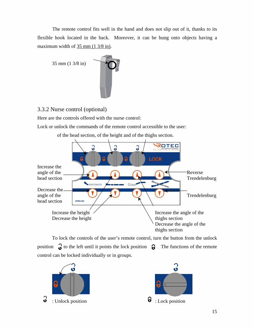
The remote control fits well in the hand and does not slip out of it, thanks to its
flexible hook located in the back. Moreover, it can be hung onto objects having a
maximum width of 35 mm (1 3/8 in).
35 mm (1 3/8 in)
3.3.2 Nurse control (optional) Here are the controls offered with the nurse control:
Lock or unlock the commands of the remote control accessible to the user:
of the head section, of the height and of the thighs section.
Increase the angle of the Reverse head section Trendelenburg Decrease the angle of the Trendelenburg head section
Increase the height Increase the angle of the Decrease the height thighs section Decrease the angle of the
thighs section
To lock the controls of the user’s remote control, turn the button from the unlock
position to the left until it points the lock position . The functions of the remote
control can be locked individually or in groups.
: Unlock position : Lock position
16
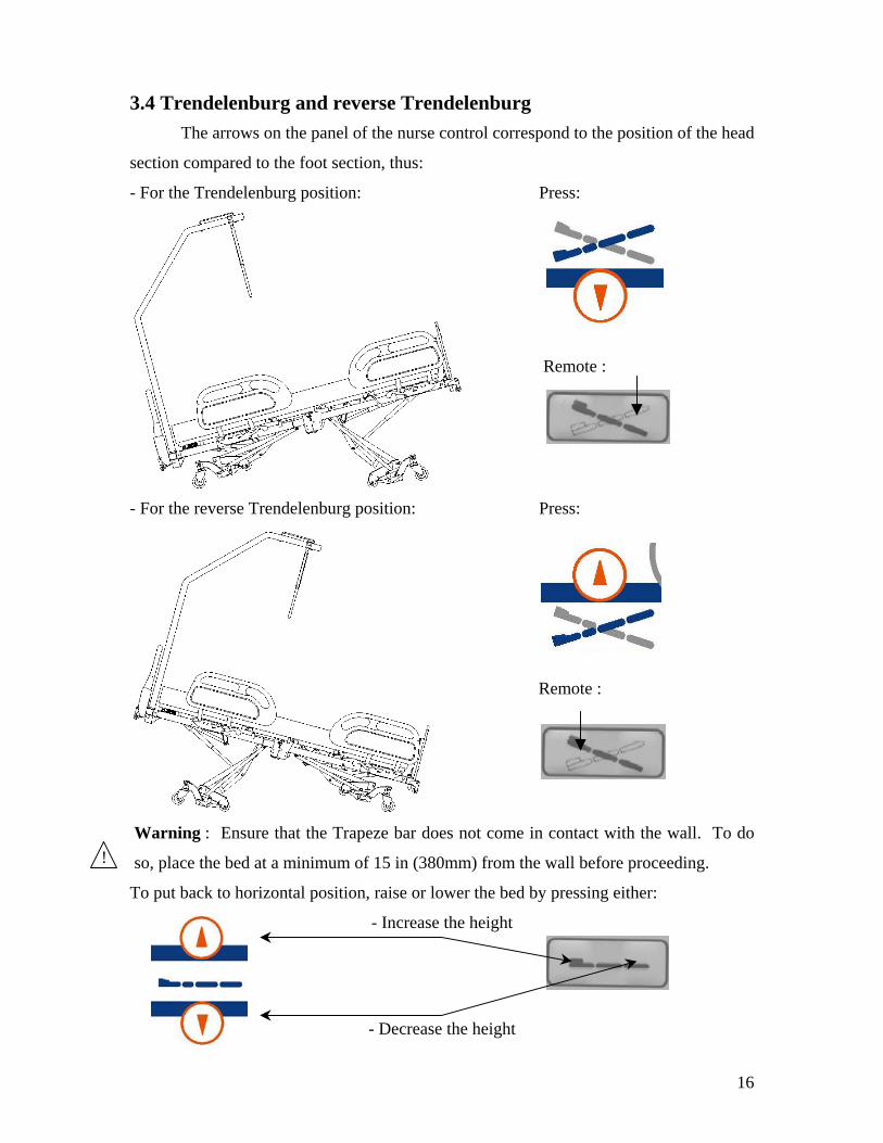
3.4 Trendelenburg and reverse Trendelenburg The arrows on the panel of the nurse control correspond to the position of the head
section compared to the foot section, thus:
- For the Trendelenburg position: Press:
- For the reverse Trendelenburg position: Press:
Warning : Ensure that the Trapeze bar does not come in contact with the wall. To do
so, place the bed at a minimum of 15 in (380mm) from the wall before proceeding.
To put back to horizontal position, raise or lower the bed by pressing either:
- Increase the height
- Decrease the height
!
Remote :
Remote :
17
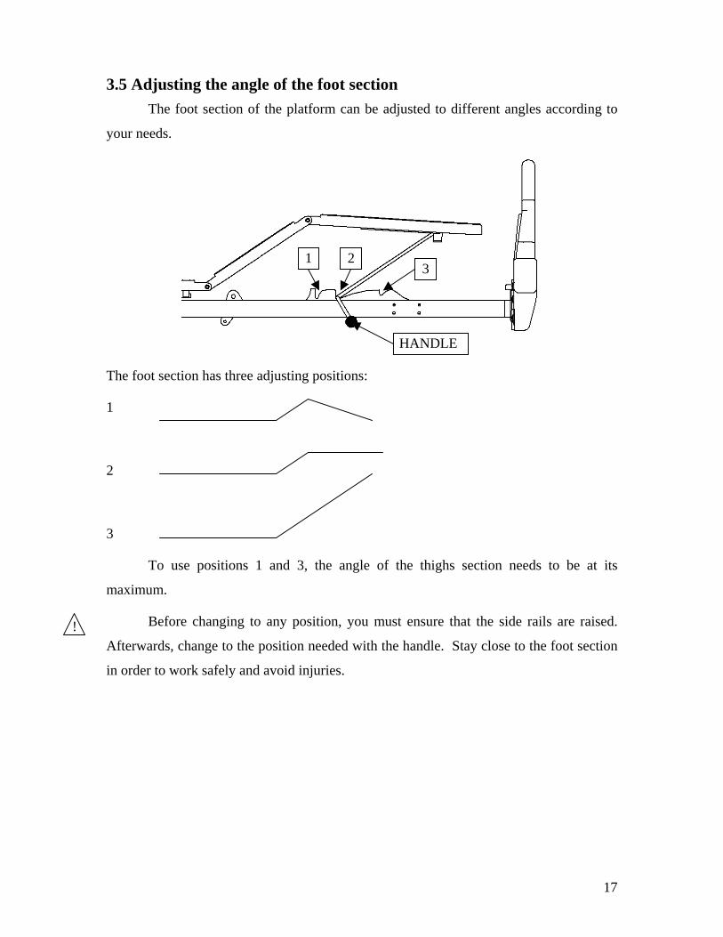
3.5 Adjusting the angle of the foot section The foot section of the platform can be adjusted to different angles according to
your needs.
The foot section has three adjusting positions:
1
2
3
To use positions 1 and 3, the angle of the thighs section needs to be at its
maximum.
Before changing to any position, you must ensure that the side rails are raised.
Afterwards, change to the position needed with the handle. Stay close to the foot section
in order to work safely and avoid injuries.
1 23
HANDLE
!

18
3.6 Hooks for draining bags The two (2) hooks for the draining bags are located under and on each side of the
lower back section of the platform.
The eight (8) openings for the restraining straps located on each side of the lower
back and the thighs sections of the platform can also be used for draining bags.
NOTE: The four (4) openings located on each side of the thighs section can be
moved when the angle is modified. Ensure that the bag does not hook the side rails when
moving.
3.7 Openings for restraining straps The twelve (12) openings for restraining straps are located on each side of the
platform (see p.8). It is the medical staff’s responsibility to use properly the restraining
straps and to choose the appropriate openings. Make sure that the straps do not tighten
more when moving the platform.
3.8 I.V. pole holders Two (2) of the six (6) holders are located at the lower back section of the platform
and four (4) are fixed on each corner of the structure.
I.V. pole holders (2)
Lower back section
I.V. pole holders (2)
I.V. pole holders (2)
Hooks for draining bags (2)

19
3.9 Using the accessories 3.9.1 Side rails Refer to the booklet inserted in this manual or in the box with the side rails.
3.9.2 Casters with synchronized brake system To facilitate access to the brake system, it is recommended to raise the height of
the bed to at least 150mm (6 in) from the lowest position.
To activate the brake system, position the pedal in one of the three following
positions :
To start the directional To remove any restriction To apply the brakes:
mode and to allow the bed and to allow the bed to
to move in a straight line : move in any direction:
push down on put the pedal push down on
the green side of the pedal. horizontally. the red side of the pedal.
* Do not move the bed sideways when the directional mode is on. This will avoid
injuries to the user and the personnel.
** Important : Make sure that the brake is not activated for all of the four casters prior
to raising or lowering the bed for the protection of floor coverings.
DIRECTIONAL* NEUTRAL BRAKE**
!
20
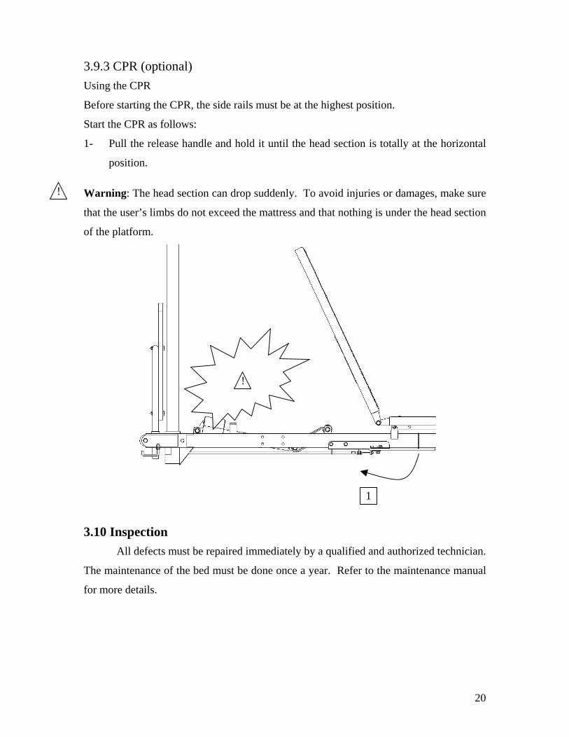
3.9.3 CPR (optional) Using the CPR
Before starting the CPR, the side rails must be at the highest position.
Start the CPR as follows:
1- Pull the release handle and hold it until the head section is totally at the horizontal
position.
Warning: The head section can drop suddenly. To avoid injuries or damages, make sure
that the user’s limbs do not exceed the mattress and that nothing is under the head section
of the platform.
3.10 Inspection All defects must be repaired immediately by a qualified and authorized technician.
The maintenance of the bed must be done once a year. Refer to the maintenance manual
for more details.
!
1
!

21
3.11 Special recommendations To install this model of bed, you need to:
- Lower the bed completely;
- Place the bed at a minimum of 50 mm (2 in) from the wall;
- Apply the brakes at the foot section;
- Apply the directional mode at the head section;
- Raise the bed to the maximum.
It is now possible to use the bed without hitting the wall.
HEAD
FOOT
HEAD
FOOT
50 mm (2 in)