owner’s manual - pool heat pumps.com documents/summit...owner’s manual. owner’s manual thank...
TRANSCRIPT

Owner’s ManualPRINTED IN CANADA 05/2009

Introduction 2
General Safety Instructions 4
Installation Instructions
Location 6
Water piping 7
Electrical 7
Bonding 8
Bonding and plumbing step-by-step instructions 8
Using an External Controller 10
Electrical Connections 11
Wiring Diagram 12
Service Analyzer Control 13
Operation 14
Caring for your Pool Heater 15
Initial Startup 16
Meaning of Display Codes 17
Troubleshooting 18
Requesting Assistance or Service 20
Maintenance 21
Winterizing 21
Pool Heat Pump Warranty 22
Table of contents
OWNER’S MANUAL
OWNER’S MANUAL
Thank you for buying a SUMMIT pool heat pump.The SUMMIT pool heat pump is a self-contained unit designed specifically for pool heating. Each component has been selected with care to achieve a high-quality product in an effort to exceed all industry standards.
All SUMMIT pool heat pumps have a Scroll compressor, an electronic board with service analyzer, a titanium heat exchanger tube warranted for 10 years against corrosion and a UV-resistant plastic cabinet that eliminates all mainte-nance for life. All components are of superior quality, which presents you with an effective, state-of-the-art technology heat pump.
In general, compared to other types of pool heaters, such as gas or oil-fired, the SUMMIT pool heat pump has a lower heating capacity on a BTU/hr basis. Therefore, it needs to operate for a longer time to accomplish the desired results. Occasionally, it may be necessary to run the heat pump for up to 24 hours per day. However, this should not be of concern to the owner because the heater is designed to operate continuously. What’s more, despite continuous operation, it will still heat the pool far more economically than other types of heaters.
As with all pool heaters, you are advised to use a pool cover at night and when the pool is not in use. The pool cover should be used if night temperatures are 15°F less than desired pool temperature. This will keep evaporation, the greatest source of heat loss, to a minimum, thus greatly reducing the overall pool heating costs. During warmer weather, the pool cover may not be required.
2

OWNER’S MANUAL
Please read carefully Record your model’s information Please complete and mail in the ownership registration card provided with this guide. The return address is displayed on the front of your registration card. Simply mail it as you would a postcard. The card helps us notify you about any new information about your heater.
Whenever you call to request service for your heater, you must know your complete model and serial numbers. You can find this information on the plate located at the base of your heater.
Please also record the purchase date of your device and your dealer’s name, address, and telephone number.
Model Number ____________________________________________________
Serial Number _____________________________________________________
Purchase Date ____________________________________________________
Dealer Name ______________________________________________________
Dealer Address ____________________________________________________
Dealer Phone _____________________________________________________
Keep this book and the sales slip together in a safe place for future reference.
3
Service can now be obtained by calling these phone numbers.
CANADA: 1 888 238-7665USA: 1 908 355-7995

OWNER’S MANUAL
General Safety Instructions We care for our customers We have provided important safety messages in this manual and on your heater. Always read and obey all safety messages.
IMPORTANTThe IMPORTANT sign calls attention to a note that provides important information or information essential to the completion of a task.
CAUTIONThe CAUTION sign denotes a hazard. It calls attention to an operating procedure, practice, or the like, which, if not correctly performed or adhered to, could result in material damage, particularly to the product, up to the destruction of part or all of the product.
WARNINGThe WARNING sign denotes a hazard. It calls attention to a procedure, practice, or the like, which, if not correctly performed or adhered to, could result in personal injury or injury to a third party. These signs are rare, but are extremely important.
?
!
4
OWNER’S MANUAL
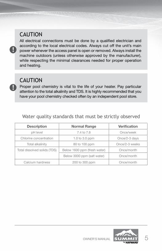
Water quality standards that must be strictly observed
CAUTIONAll electrical connections must be done by a qualified electrician and according to the local electrical codes. Always cut off the unit’s main power whenever the access panel is open or removed. Always install the machine outdoors (unless otherwise approved by the manufacturer), while respecting the minimal clearances needed for proper operation and heating.
!
CAUTIONProper pool chemistry is vital to the life of your heater. Pay particular attention to the total alkalinity and TDS. It is highly recommended that you have your pool chemistry checked often by an independent pool store.
!
Description Normal Range Verification
pH level 7.4 to 7.8 Once/week
Chlorine concentration 1.0 to 3.0 ppm Once/2-3 days
Total alkalinity 80 to 100 ppm Once/2-3 weeks
Total dissolved solids (TDS) Below 1600 ppm (fresh water) Once/month
Below 3000 ppm (salt water) Once/month
Calcium hardness 200 to 300 ppm Once/month
5

OWNER’S MANUAL
Installation Instructions Location The placement of the pool heater is very important in keeping installation costs to a minimum while providing for maximum efficiency of operation, as well as allowing adequate access for service and maintenance.
The SUMMIT pool heat pump is designed for outdoor installation and should not be installed in a fully enclosed area, such as a shed, garage, etc., Recirculation of cold discharged air back into the evaporator coil will greatly reduce unit heating capacity and efficiency.
The unit should be located as close as practical to the existing pool pump and filter to minimize water piping. However, do not forget to provide a 24” clear-ance at the very least all around your heat pump. The use of 90 degree bends and short radius elbows in the water piping should be kept to a minimum.
Mount the unit on a sturdy base, preferably a concrete slab or a set of blocks. The base should be completely isolated from the building foundation wall to prevent the possibility of sound or vibration transmission into the building. The size of the base should not be less than 36” x 36” (92 cm x 92 cm).
All SUMMIT pool heat pump models feature ultra-silent ventilation systems. Air is pulled through the evaporator coil and discharged through the top grille. A minimum clearance of 48 inches should be allowed above the unit for unrestricted air discharge. The unit must not be installed under a porch. Any side of the unit should be located at least 24 inches from a wall or from any other obstruction for unre-stricted air intake and service access.
IMPORTANT?
48”24”
24”
24”
6

OWNER’S MANUAL
Water piping
The piping sequence is as follows: pool pump > filter > heater > pool. Auto-mated chlorine distribution systems, if used, must be placed downstream of the heater to minimize harm to the pool equipment. Use rigid PVC piping if possible (SCH40 or SCH80). All joints should be glued with PVC glue. When the piping installation is complete, operate the pool pump and check the sys-tem for leaks. Then, check the filter pressure gauge to verify that there isn’t any indication of excessive pump head pressure.
You can also make the connections using high-pressure flexible hose, but make sure the hose can withstand high pressure. The installation of a bypass is not necessary unless the water flow exceeds 80 GPM.
Note: Certain installations have valves which isolate the heat pump from the water circuit. If the heat exchanger is deprived of water circulation for several days, high chlorine gas could cause excessive corrosion. If the disconnect switch is turned off, be sure that the pool water is allowed to circulate through the unit, or is drained out of it.
Electrical
The wiring of your SUMMIT pool heat pump should be performed by a quali-fied electrician in accordance with local requirements.
A properly-sized breaker and copper wire must be used.
The unit must always be powered off before opening the access panel.
IMPORTANT?
CAUTION!
WARNING
7

OWNER’S MANUAL
Bonding
Because all metals have different electrical potentials, all metal and electrical components of the pool system must be bonded together. This includes the metal framework of the pool, the light, the pump, the filter (if made out of metal), the heater, any automatic chlorine generator, and any other metal or electrical equipment. On some older pools, this substructure bond wire may not exist. In these cases, a 6 to 8 foot solid copper rod must be driven into the ground near the equipment. All electric and metal components must then be bonded to each other, and then to the copper rod.
CAUTION!
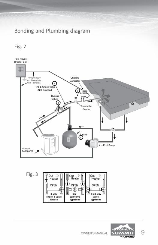
1. A 1/3 lb check valve must be installed between the heater and any automatic chlorine distribution system (if used).
2. Any kind of automatic chlorine distribution system must be installed after or downstream of the heat pump.
3. The filter must be placed before or upstream from the heat pump.
4. A bypass and shut-off should be installed on all systems for ease of service, maintenance and to balance the water flow. Bypasses must be installed on any system with over a 1 1/2 HP pool pump. (see FIG.3 for different types of possible bypasses)
Bonding and Plumbing step-by-step instructions
8
OWNER’S MANUAL
Bonding and Plumbing diagram
Fig. 2
Fig. 3
SUMMIT
9

OWNER’S MANUAL10
Using an External Controller To connect the electronic board in order to control it remotely, use the P_S terminals on the right side of the board. Next, access the P_S menu and select the desired mode. In internal mode, POOL or SPA mode can be adjusted by using this menu. In external mode, a normally open contact puts the board in POOL mode and a closed contact puts the board in SPA mode. Therefore, a board set to OFF in POOL mode and to 80 degrees in SPA mode can be controlled with an external switch to heat up to 80 degrees.
Internal mode: Use the P_S mode on the main menuExternal mode: • Open contact = POOL mode • Closed contact = SPA mode
Control using a switchTo control the board using an external switch, follow these steps : • Turn on the heat pump.• Set POOL mode to OFF.• Set SPA mode to the desired temperature. • Access the setup menu.• Select mode E (external) on the P_S menu.• Run two J7 (P_S) terminal wires from the HPEC-003
board to the NO switch terminals (see FIG. 4A).• You can now control the operating mode by turning
off the switch (open = POOL, closed = SPA.)
Control using an Aqua Logic system To control the board by using an Aqua Logic system, follow these steps: • Turn on the heat pump.• Set POOL mode to OFF.• Set the SPA mode to the maximum (104°F).• Access the setup menu.• Select mode E (external) on the P_S menu.• Run two J7 (P_S) terminal wires from the HPEC-003
board to the HEATER RELAY 1 terminals of the Aqua Logic system (see FIG. 4B).
• You can now control the operating mode using the Aqua Logic system remote control.
External switchPool (open)Spa (closed)
Fig. 4A
Fig. 4B
To terminal wiresHEATER 1
RELAY

OWNER’S MANUAL
Electrical Connections
The installation of the SUMMIT pool heater should be performed by a certi-fied electrician. To connect the electricity, you must unscrew the five screws of the front panel, then slide the electric cable in the hole located on the left or the right side of the base, and then insert it in the control box. The electrical diagram is located on the lid of the control box as well as below (see FIG.5).
WARNING
Ground
L1L2
Fig. 5Power requirements 240 V, 1 PH, 60 Hz
Look at the name plate loca-ted on the heat pump to know the required amperage.
Please refer to your local electrical code.
11
OWNER’S MANUAL
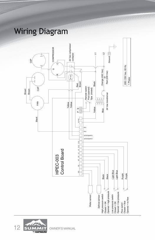
Wiring Diagram
12
Bla
ck
Blu
e
Yel
low
Bla
ckF
AN
CO
MP
RE
SS
OR
CR
S
Red
Bro
wn
Bro
wn
Bro
wn
HP
EC
-003
Con
trol
Boa
rd
L1 L2B
lack
Bla
ck
Ligh
t Blu
e
Ligh
t Blu
e
Pur
ple
Pur
ple
Yel
low
Yel
low
Wat
er s
enso
r
Def
rost
sen
sor
Hig
h pr
essu
re s
witc
h
Clo
sed
= O
KO
pene
d =
hig
h pr
essu
re
Low
pre
ssur
e sw
itch
Clo
sed
= O
KO
pene
d=
low
pre
ssur
e
Flo
w s
witc
hC
lose
d =
flow
Ope
ned
= n
o flo
w
Rem
ote
switc
hP
ool (
open
ed)
Spa
(cl
osed
)
Ora
nge
(240
Vac
)or
Red
(20
8 V
ac)
24 V
ac c
ompr
esso
rco
ntac
tor
CA
P
24 V
ac tr
ansf
orm
erG
roun
d
PS
WS
DS
HP
HP
LPLP
FLO
FLO
FAN
FAN
COMPRESSOR
COMPRESSOR
24
VA
C
208
/ 230
Vac
,60
Hz
1 P
hase
CA
P
24 V
ac
OWNER’S MANUAL
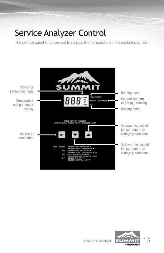
Service Analyzer Control The control panel is factory set to display the temperature in Fahrenheit degrees.
13
Temperature and parameter
display
Celsius or Fahrenheit mode
Access to parameters
To raise the desired temperature or to change parameters
To lower the desired temperature or to change parameters
Heating mode
Compressor ( ) or fan ( ) running
Heating mode
OWNER’S MANUAL
Operation To increase the temperature Push the SET key until you see POL or SPA. The programmed temperature will be displayed. Press the UP arrow to increase the temperature setting one degree at a time.
To lower the temperature Proceed as explained above using the down arrow .
To select the pool or spa mode The unit can keep two temperature settings in memory: one for pool mode (max: 95°F/35°C), and the other for spa mode (max: 104°F/40°C). To have access to either program, press the SET key until you see P_S and by press-ing one of the arrow keys, you can switch to POL or SPA. Once the heating mode has been programmed, it will be displayed for five seconds, and will then return to the actual pool water temperature. The lights on the right side of the display indicate the chosen heating mode.
To display the temperature in °F or in °C Press the SET key until you see F_C and by pressing one of the arrow keys, you can switch to °F or °C. Once the heating mode has been programmed, it will be displayed for five seconds, and will then return to the actual pool water temperature in the mode that you have chosen.
14

OWNER’S MANUAL
Caring for your Pool Heater How to protect your pool heater
15

OWNER’S MANUAL
Initial Startup
Before starting the pool heater for the first time, it is important to verify that the breaker is in the ON position.
Also make sure that the water circulates freely and that the pool pump is activited.
Then, you will need to set the water temperature you desire. The fan will immediately start. The compressor will start after a 3 to 4-minute delay.
When the compressor is running, the HEATING/CHAUFFAGE indicator located on the right (see “Service Analyzer Control,” p. 13) should be lit. At initial startup, it is normal for the unit to run 24 hours a day.
It is also normal to see water dripping from the holes at the base of the unit. This is just condensation.
IMPORTANT?
16

OWNER’S MANUAL 17
Meaning of Display Codes Service Analyzer CodesMost problems will be detected by the service analyzer and a code will be displayed on the digital display of your heater.
Display Meaning of codes OFF The desired programmed temperature point is lower than 60°F
(15°C).
LP & LP3 Shortage of refrigerant gas in the unit or faulty low pressure control. The digital display will show LP3 after 3 LP faults and shut down your pool heater. The pool pump will also be stopped for pro-tection if the unit’s internal time clock feature is used. If LP or LP3 occurs you should call for service.
HP & HP3 Low water flow to the unit or faulty high pressure control. Check wa-ter flow. Backwash filter and/or heater. The unit will show HP3 after 3 HP faults. This will stop your heater for protection.
Po Water temperature probe connected to #1 and #2 on electronic board may be disconnected. If it is not, the probe may be open or defective.
Pc Water temperature probe is short circuited or may be defective.
FLo Possible causes: - The filter is in backwash position. - The filter pump is stopped. - The filter is dirty. - Shortage of water to pool pump. - Water pressure switch must be adjusted or it is broken.
dPo Suction temperature probe connected to #3 and #4 on electronic board may be disconnected. If it is not, the probe may be open or defective.
dPc Suction temperature probe is short circuited or may be defective.
FS Unit currently in defrosting cycle (the fan works but the compressor is stopped). This is normal operation when outside temperatures are cold.

OWNER’S MANUAL
The heat pump is in protection mode.
The unit is on defrost cycle.
In this case, there may be a 5-minute delay before restarting.
Digital display should indicate FS. The compressor will automatically start again a few minutes after the display stops indicating FS.
The fan is running, but the compressor is not.
Pool pump is not running.
Filter is dirty, restricting the water flow.
Turn the pool pump on.
Backwash and clean filter.
The heater is displaying “flo” and it will not start.
Heat pump control set to OFF.
Desired water temperature is reached.
Main breaker is tripped.
Raise temperature set point above 60°F (15°C).
Unit will automatically restart when the water temperature goes below the set point.
Reset it.
The pool heater is not running.
Troubleshooting
18
OWNER’S MANUAL
Note: If your pool heater does not operate for reasons other than those mentioned above, please contact Consumer Assistance Center (see “Introduction”, p. 3) to obtain the proper authorization for the warranty to apply.
Ask your electrician to verify your heat pump’s power supply by checking over the L1 and L2 connections in the unit’s service box.
There is no display and the fan is not running, but the compressor is running.
While your SUMMIT pool heater is in the heating mode, a large quantity of warm and humid air passes over the evaporator and causes con-densation. It is normal to see condensation dripping under the heater.
To check if the water really is a leak, you must stop the heater and leave the pool pump running for over 5 hours. If water is still coming out of your heater after this period, then call your dealer for service.
There is water around the unit.
Heat loss is too much for the heater; cover your pool as often as you can.
Evaporator restricted due to improper location (see “Location”, p.6).
Evaporator is dirty.
Restricted water flow.
Clean it.
Adjust water flow.
The heater is running but desired water temperature cannot be reached.
19

OWNER’S MANUAL
Requesting Assistance or Service
All service will be handled by an Authorized Service Center. Warranty may be voided if service is not done by an Authorized Service Representative. Do not return the heater to your dealer as they do not provide service.
Before calling for assistance or service, please check the “Troubleshooting” (pp. 18-19) and “Warranty” (p. 22) sections or call your dealer. It may save you the cost of a service call. If you still need help, follow the instructions below.
Service can be obtained by calling one of these phone numbers.CANADA: 1 888 238-7665 USA: 1 908 355-7995
When asking for help, please provide a detailed description of the problem, your heater’s complete model and serial number, and the purchase date (see p. 3). This information will help us respond properly to your request.
Keep a copy of the sales receipt showing the date of purchase. Proof of purchase will assure you warranty service.
IMPORTANT?
20

OWNER’S MANUAL
MaintenanceDirt can accumulate on the evaporator. You can easily remove it by using a water spray without damaging the small aluminum fins.
The cleaning of the plastic cabinet can be done with the help of a brush and soap.
Winterizing First, you must turn the breaker off. The unit must be drained of all its water. You will need to disconnect the IN and OUT water connections. Then the unit must be tilted or blown out with air until all water is out.
The next step is to reconnect your IN and OUT water connections that will have previously been drained.
It is recommended to cover the heat pump to prevent snow from getting inside. A protective winter cover is also offered by your retailer.
21

OWNER’S MANUAL
Pool Heat Pump WarrantyHayward Industries warrants that the SUMMIT pool heat pump will be free of defects in workmanship and materials. The heat pump will be warranted for a period of two (2) years*. All parts and labor to correct any defect in workmanship or materials will be the responsibility of Hayward Industries.
The compressor component of the SUMMIT pool heat pump has a five (5) year limited warranty. During the first two (2) years*, the costs incurred by the parts and labor needed to repair the compressor will be the responsibility of Hayward Industries. During years three (3), four (4) and five (5), only parts will be covered by the warranty.
The titanium tube portion of the heat exchanger in the SUMMIT pool heat pump has a limited 10-year warranty. The titanium tube portion of the heat exchanger is warranted to the original owner and at the original address. All parts and labor are warranted for a period of two (2) years* to the original home owner. After two (2) years*, only the titanium tube portion of the heat exchanger part is warranted.
All SUMMIT pool heat pump must be installed according to manufacturer’s speci-fications or the warranty will be null and void.
All warranty work must be performed by a Hayward Industries authorized service center. All warranty work must be approved prior to service center performing the work.
Any alteration or repair by any person, agency or company not authorized by Hayward Industries will void the warranty. Hayward Industries is not liable for any damages of any sort whatsoever, including incidental and consequential damag-es. This warranty does not include damage to any internal piping or components due to freezing conditions, negligence, abuse, routine maintenance inspections, electrical wiring outside the heat unit, service calls caused by owner, external valve position, refrigerant or other expendable materials, installations in corrosive environments or atmospheres, nor acts of God. There are no particular warranties of merchantability that apply to this product.
This warranty applies to Canada and the Unites States.
Hayward Industries will replace or repair any parts that are defective providing such parts are returned to the SUMMIT factory, freight collect, within the warranty period. The above is the exclusive remedy from Hayward Industries.
* The 2-year warranty applies only in Canada or within the State of Florida. In the USA, outside the State of Florida, the SUMMIT pool heat pump is warranted for a period of two (2) years for parts and one (1) year for labor.
22