owner’s manual pro-1200w, pro-1600w pro-2000w,...
TRANSCRIPT

OWNER’S MANUAL
Pro-1200W, Pro-1600WPro-2000W, Pro-2500W
Pro-3000WPOWER INVERTERS
THE WHISTLER GROUP, INC.CORPORATE HEADQUARTERS3604 N.W. Frontage Rd.Bentonville, AR 72712TEL (479) 273-6012 FX (479) 273-2927www.whistlergroup.com
CUSTOMER RETURN CENTER551 N. 13th St.Rogers, AR 72756Customer Service Tel (800) 531-0004Email: [email protected]
P/N 401516© 2010 The Whistler Group, Inc.
pro1200to3000w.qxp 4/30/2010 8:54 AM Page 1

1
If you have questions concerning theoperation of this Whistler productplease call customer service:
1-800-531-0004Hours:
Monday - Friday8:00 am - 5:00 pm CT
Please keep the receipt in a safe place.You may register your product online atwww.whistlergroup.com. If the unit isreturned without a dated proof ofpurchase, an out of warranty servicecharge applies. Note: Your warrantyperiod begins at the time of purchase.The warranty is validated only by yourreceipt.
Now is the time to record the serialnumber of the unit in the space providedin the warranty section of the manual.
INTRODUCTION
Dear Whistler Owner,
For many of us, a vehicle is more than just transportation. Itcan be a mobile office, communications or entertainmentcenter, or simply an expression of our personality. Whistlerproducts are designed to make the time you spend in yourvehicle more productive, more fulfilling, safer, or just simplymore fun. Our mission is to provide products that improveyour driving experience.
Whistler offers a complete line of DC to AC inverters rangingfrom 100 Watts to 3000 Watts. These inverters offer advancedtechnology, dependable operation and will provide years ofreliable service when used in accordance with our operatinginstructions.
Your new Whistler power inverter allows you to run most ACappliances right from your car, boat or RV. They’re great forweekend use and life on the road. They’re also great forpower outages. To fully acquaint yourself with the operationof this power inverter, we recommend reading this entiremanual.
Sincerely,
THE WHISTLER GROUP, INC.
pro1200to3000w.qxp 4/30/2010 8:54 AM Page 3

WHISTLER FEATURES
A Word About Whistler Power Inverters
Whistler inverters convert low voltage, direct current (DC) to 110volt alternating household current (AC). The AC output is called“modified sine wave”. See “Technical Operating Principles”section for more information. Depending on the model and itsrated capacity, Whistler inverters draw power either from standard12 volt automobile and marine batteries or from portable highpower 12 volt sources.
Inverter Features
3
Topic Page
Features Summary ..................................................................3-5
Important Information................................................................6
Inverter Information ..............................................................7 - 9
• Getting Started
• Don’t Push It
Battery Information...........................................................10 - 11
• Selecting the Optimum Power Source
Cable Information .............................................................11 - 12
• Wire Cable Gauges
Operation ..........................................................................13 - 20
• Making the Connection
• The Power Source
• TV Fans and Audiophiles
• Microwaves
• Powerful Advice
• Technical Types
Technical Operating Principles ........................................21 - 22
Operation Summary .........................................................22 - 23
Troubleshooting ................................................................24 - 25
Specifications ....................................................................26 - 27
Warranty Information........................................................28 - 30
TABLE OF CONTENTS
2
Note: Front panel layout andcontrols are similar for models1200 watt and up.
“A” = Pro-2000w & up models “B” = Pro-1200W & Pro-1600W
pro1200to3000w.qxp 4/30/2010 8:54 AM Page 5
FEATURES
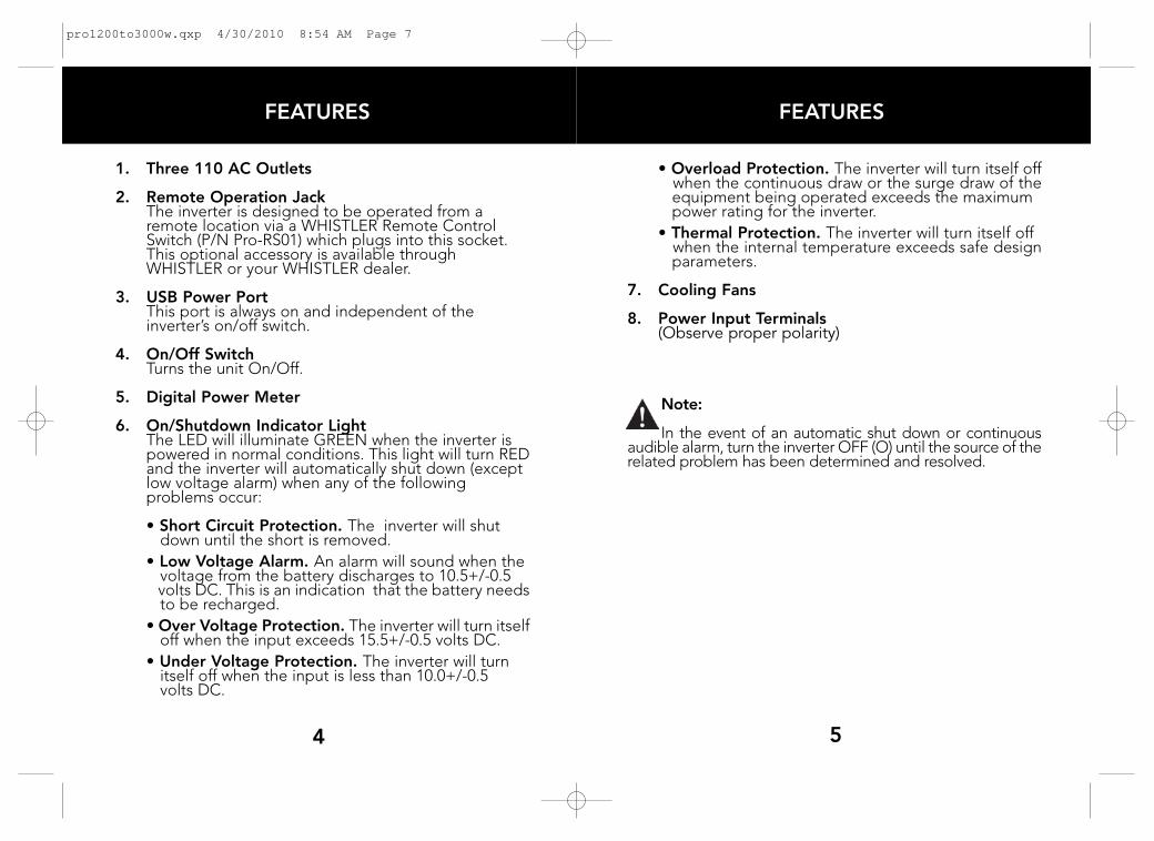
1. Three 110 AC Outlets
2. Remote Operation JackThe inverter is designed to be operated from a remote location via a WHISTLER Remote Control Switch (P/N Pro-RS01) which plugs into this socket. This optional accessory is available through WHISTLER or your WHISTLER dealer.
3. USB Power PortThis port is always on and independent of the inverter’s on/off switch.
4. On/Off SwitchTurns the unit On/Off.
5. Digital Power Meter
6. On/Shutdown Indicator LightThe LED will illuminate GREEN when the inverter is powered in normal conditions. This light will turn REDand the inverter will automatically shut down (except low voltage alarm) when any of the following problems occur:
• Short Circuit Protection. The inverter will shut down until the short is removed.
• Low Voltage Alarm. An alarm will sound when the voltage from the battery discharges to 10.5+/-0.5 volts DC. This is an indication that the battery needsto be recharged.
• Over Voltage Protection. The inverter will turn itselfoff when the input exceeds 15.5+/-0.5 volts DC.
• Under Voltage Protection. The inverter will turn itself off when the input is less than 10.0+/-0.5 volts DC.
5
FEATURES
4
• Overload Protection. The inverter will turn itself offwhen the continuous draw or the surge draw of theequipment being operated exceeds the maximum power rating for the inverter.
• Thermal Protection. The inverter will turn itself off when the internal temperature exceeds safe designparameters.
7. Cooling Fans
8. Power Input Terminals(Observe proper polarity)
Note:
In the event of an automatic shut down or continuousaudible alarm, turn the inverter OFF (O) until the source of therelated problem has been determined and resolved.
pro1200to3000w.qxp 4/30/2010 8:54 AM Page 7

INVERTER INFORMATION
Important Information About Your New Whistler Inverter.This manual will provide you with directions for the safeand efficient operation of your Whistle Power Inverter.Read the manual carefully before using your new Whistlerinverter and keep the manual on file for future reference.
Important Note: Each of the following operating proceduresand safety features must be carefully reviewed andthoroughly understood prior to using the inverter. Failureto do so may result in damage to the inverter, equipmentor serious personal injury.
Notes:Your Whistler inverter is designed to operate from a 12 voltpower source only. Never attempt to connect yourWhistler inverter to any other power source, including anyAC power source.
• 110 volts can be lethal. Improper use of your Whistlerinverter may result in property damage, personalinjury or loss of life.
• Do not connect the inverter’s output to any otherpower source.
• Not recommended for use with medical equipment. Check with the appliance manufacturer for compatibility with modified sine wave inverters.Some appliances may not work well, not at all or bedamaged. This is especially true for medical equipment.For more information on compatibility issues, please visitour inverter FAQ page at: www.whistlergroup.com
7
IMPORTANT INFORMATION
6
Getting StartedPower equipment and appliances which operate with motorsor tubes require an initial surge of power to get them upand running. This power surge is referred to as the "startingload" or "peak load." (By comparison, electrical devices suchas standard light bulbs do not require a large starting load.)Once the equipment or appliance has been powered up, itsettles down to a slower pace and requires far less electrical powerto operate. This lower power requirement is referred to asthe "continuous load."
In order to ensure that the capacity of your Whistler inverteris sufficient to meet the required start up load, you must firstdetermine the power consumption of the equipment orappliance you plan to operate.
Power consumption is rated either in wattage or amperes,and information regarding the required "watts" or "amps"generally is stamped or printed on most appliances andequipment. If this information is not indicated on the applianceor equipment, check the owner’s manual. Contact theappliance or equipment manufacturer to determine ifthe device you are using (TV’s, battery charger, computer,etc.) is compatible with a modified sine wave.
If the power consumption is rated in amps, multiply the numberof amps by 110 (AC voltage) to determine the comparablewattage rating. Induction motors may require 2 to 6 timestheir wattage rating to start up.
For further information on the fundamental operatingprinciples of Whistler inverters and related technicaldata, see "Technical Operating Principles."
pro1200to3000w.qxp 4/30/2010 8:54 AM Page 9

power overload. Testing appliances and equipment withstart up load ratings comparable to your inverter wattagerating will not damage it.
If a piece of equipment or an appliance will not operate,first confirm that the inverter has been properly connectedto the 12 volt power source (See "Making The Connection").If all connections have been properly made, turn the inverterrocker switch ON (l), OFF (O) and ON (l) again in quick succession. If this procedure is unsuccessful, it is likely thatthe inverter does not have the required start up capacity oryour battery supply isn’t large enough to operate theequipment or appliance in question.
Selecting the Optimum Power Source.
Operating the inverter for extended periods combined witha high continuous load demand may result in excessivepower drain from the battery. Therefore, the reserve capacityof the battery you select to power the inverter is animportant consideration.
The potential power drain can be estimated by calculatingthe reserve power ("amp-hour"or Ah) of the battery andthe amps required by the inverter to meet the continuousload demand of the equipment or appliance beingoperated.
INVERTER INFORMATION
Don’t Push It.
Although your Whistler power inverter has the capacity toprovide power output (excess current) equal to approximatelytwo times its rated wattage capacity for a very brief period,it is designed to operate equipment and appliances withstart up load wattage ratings no higher than its own maximumcontinuous wattage rating.
For example, the Pro-1200W model has a maximumcontinuous rating of 1200 watts. Although this model hasthe capacity to briefly provide more than its continuouspower (that is, excess current), it is designed to operateequipment and appliances with start up load requirements of1200 watts or less.
Consequently, if the start up load rating of your equipmentor appliance is slightly higher than the maximum continuousrating of the inverter, the inverter will attempt to start loadsabove the continuous rating.
Some refrigerators, freezers, pumps and other similarequipment and appliances require very high start up loadsto operate. Before attempting to power up this type ofequipment or appliance, make certain that all connectionshave been properly made and that the power source is fullycharged.
To determine whether your inverter will operate a particularpiece of equipment or appliance, run a test. The inverter isdesigned to shut down automatically in the event of a
9
INVERTER INFORMATION
8
pro1200to3000w.qxp 4/30/2010 8:54 AM Page 11

11
BATTERY/CABLE INFORMATION
• It may be advisable to operate the inverter from a bankof batteries of the same type in a "parallel" configuration.Two such batteries will generate twice the Ah of asingle battery; three batteries will generate threetimes the Ah and so on. See “Making a Connection”on page 13 for more information.
This multiple parallel battery option is especially recommended for the Pro-2500W and Pro-3000Winverters due to the high level of amps these modelsrequire to produce up to 3000 watts of continuousload. For more information regarding battery powerplease visit our inverter faq page at:www.whistlergroup.com.
Wire Cable Gauges
For safe and proper operation of the inverter, connect theinverter to the power source with the proper gauge availableand in the shortest length practical.
Pro-1200W and Pro-1600W
When the inverter and the battery are set up within three feetof each other, use a minimum of #4 gauge wire to make theconnections. Within four to six feet, use a minimum of #2 gaugewire (Pro-1200W), #0 gauge for Pro-1600W. At distancesbetween six feet to ten feet, use #0 gauge wire (Pro-1200W),#00 gauge for Pro-1600W.
BATTERY INFORMATION
10
1. To calculate the Ah of the battery, first determine its"reserve minutes" rating. (Deep cycle marine batteriesgenerally have the highest reserve minute ratings). Thisrating typically is marked on the battery along with the"Cold Cranking Amps" (CCA) rating. Multiply the reserveminutes rating of the battery by 0.3 to determine thebattery approximate Ah rating. A battery with a reserveminutes rating of 166 has an Ah rating of 49.8.
2. To estimate the maximum battery current the inverterwill require to run a piece of equipment or appliance,divide its continuous load wattage requirement by 10.
The Pro-1200W watt model utilizes 50 amps of batterypower to operate an appliance with a 500 watt continuousload requirement. (500W divided by 10V = 50A).
3. Conclusion: The reserve power of the battery is sufficientto satisfy the continuous load demand placed on theinverter for a maximum of about one hour. (49.8 Ahdivided by 50A = 1 hour).
Note:• When the inverter will be operating equipment or
appliances with high continuous load ratings for extendedperiods, it is not advisable to power the inverter with thesame battery used to power your vehicle. If the car or truckbattery is utilized for an extended period, it is possible thatthe battery voltage may be drained to the point wherethe battery has insufficient reserve power to start the vehicle.
pro1200to3000w.qxp 4/30/2010 8:54 AM Page 13

Pro-2000W and Pro-2500W
When the inverter and the battery are set up within threefeet of each other, use a minimum of #2 gauge wire to makethe connections. Within four to six feet, use a #0 gauge wire(Pro-2000W), #00 gauge for Pro-2500W. At distancesbetween six feet to ten feet, use #000 gauge wires (Pro-2000W), #0000 for Pro-2500W connected in parallel to thebattery.
Pro-3000W
When the inverter and the battery are set up within threefeet of each other, use a minimum of #0 gauge wire to makethe connections. Within four to six feet, use a #000 gaugewires. At distances between six feet to ten feet, use 2 sets of#00 gauge wires connected in parallel to the battery.
Check Whistler’s online store for cable availability.
Cable options: For model Pro-2500 at 10 foot length, asubsitute for the #0000 gauge can be using 2 sets of #0gauge wires connected in parallel to the battery.
12
CABLE INFORMATION OPERATION
Making the Connection.
1. Make certain that the Power switch is in the OFF (O) position.
2. Connect the cables to the power input terminals at therear of the inverter and tighten the screws to make asecure connection.
(To make these connections, install the wireconnectors flush with the metal backing plates andfasten the nuts securely.
3. Connect the cable from the Negative (-) terminal onthe inverter to the Negative (-) terminal on the 12 voltpower source. Make certain the connection is secure.
4. Confirm that the cable you have just installed isproperly connected. Specifically, make certain thatthe cable is connected to the Negative (-) terminalson both the inverter and the 12 volt power source.
5. Connect the cable from the Positive (+) terminal onthe inverter to the Positive (+) terminal on the powersource.
13
pro1200to3000w.qxp 4/30/2010 8:54 AM Page 15
1514
OPERATION OPERATION
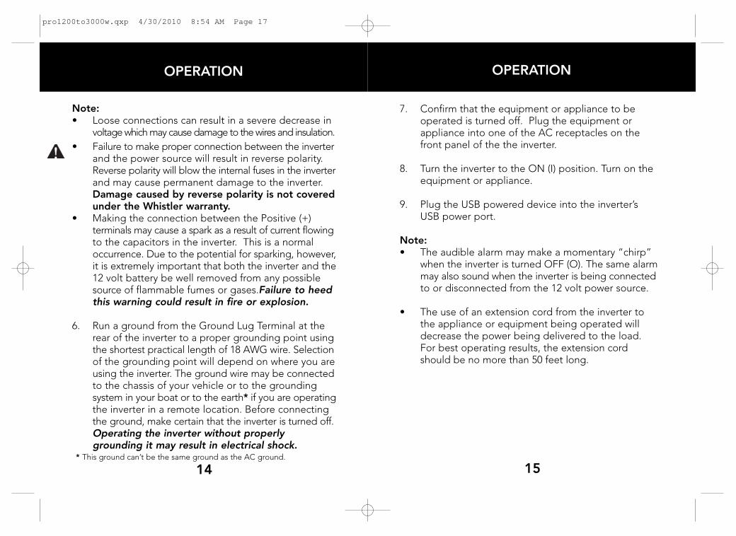
7. Confirm that the equipment or appliance to beoperated is turned off. Plug the equipment orappliance into one of the AC receptacles on thefront panel of the the inverter.
8. Turn the inverter to the ON (I) position. Turn on theequipment or appliance.
9. Plug the USB powered device into the inverter’sUSB power port.
Note:• The audible alarm may make a momentary “chirp”
when the inverter is turned OFF (O). The same alarmmay also sound when the inverter is being connectedto or disconnected from the 12 volt power source.
• The use of an extension cord from the inverter tothe appliance or equipment being operated willdecrease the power being delivered to the load.For best operating results, the extension cordshould be no more than 50 feet long.
Note:• Loose connections can result in a severe decrease in
voltage which may cause damage to the wires and insulation.
• Failure to make proper connection between the inverterand the power source will result in reverse polarity.Reverse polarity will blow the internal fuses in the inverterand may cause permanent damage to the inverter.Damage caused by reverse polarity is not coveredunder the Whistler warranty.
• Making the connection between the Positive (+) terminals may cause a spark as a result of current flowingto the capacitors in the inverter. This is a normaloccurrence. Due to the potential for sparking, however,it is extremely important that both the inverter and the12 volt battery be well removed from any possiblesource of flammable fumes or gases.Failure to heedthis warning could result in fire or explosion.
6. Run a ground from the Ground Lug Terminal at therear of the inverter to a proper grounding point usingthe shortest practical length of 18 AWG wire. Selectionof the grounding point will depend on where you areusing the inverter. The ground wire may be connectedto the chassis of your vehicle or to the grounding system in your boat or to the earth* if you are operatingthe inverter in a remote location. Before connectingthe ground, make certain that the inverter is turned off.Operating the inverter without properlygrounding it may result in electrical shock.
* This ground can’t be the same ground as the AC ground.
pro1200to3000w.qxp 4/30/2010 8:54 AM Page 17
OPERATIONOPERATION
16
• Check frequently to ensure that the input and output connections are secure. Loose connectionsmay damage the inverter, the power source, or may generate excessive heat.
To generate the maximum output, the Pro-3000W wattmodel (for example) should be connected to a powersupply which has the capacity to produce up to 300amps. The loads should be distributed between thereceptacles to ensure that each outlet is producing nomore than its maximum 1500 watt output.
If more than one piece of equipment or appliance isto be operated at the same time, first turn on theinverter and then turn on each piece of equipment orappliance separately to enable the inverter to producethe required start up loads.
Important Information on Battery Chargers
Using your inverter with battery chargers for power tools,flashlights, video cameras and laptop computers may causedamage to the inverter or the charging unit. Check with theappliance manufacturer for compatibility with modified sinewave inverters if you’re unsure.
Although we advise against it, if you attempt to use acharging unit, monitor the temperature of the charging unitfor approximately 10 minutes. If the charging unit becomesunusually warm, disconnect it from the inverter immediately.
The Power Source.
When the engine is off, most batteries will provide ample powerto the inverter for one to two hours. The actual length of timeis a function of several variables including the age andcondition of the battery, the number of batteries and the powerdemand being placed on it by the equipment being operatedwith the inverter. If you are using the inverter while the engineis off, we recommend you start the engine every 30 to 60minutes and let it run for at least 10 minutes to recharge thebattery. We also recommend that the device plugged intothe inverter be turned off before turning over the engine.
Although it is not necessary to turn off the inverter when turningover the engine, the inverter may momentarily cease operationas the battery voltage decreases. When the inverter is notsupplying power, and is turned on, it draws low amperagefrom the battery (see specifications).
For You Television Fans & Audiophiles.
Although the inverter is shielded and filtered to minimize signalinterference, some interference with your television picture may be unavoidable, especially with weak signals. However,here are some suggestions that may improve the reception.
1. First, make certain that the television antenna produces a clear signal under normal operating conditions (i.e., at home plugged into a standard 110 AC wall outlet). Also, ensure that the antenna cable is properly shieldedand of good quality.
17
pro1200to3000w.qxp 4/30/2010 8:55 AM Page 19
1918
OPERATION OPERATION
Some Powerful Advice.
When driving with the inverter in operation, make certain thatneither the inverter nor the power cords will impede safeoperation of your vehicle. Keep the unit and all cords clearof the steering wheel, gas, brake and clutch pedals and gear shift.
To maintain your inverter in proper working condition, notethe following important safety precautions:
• MOISTURE. Keep the inverter dry. Do not expose itto moisture. Do not operate the inverter if you, theinverter, the device being operated or any other surfacesthat may come in contact with any power sources arewet. Water and many other liquids can conductelectricity which may lead to serious injury or death.
• HEAT. For peak efficiency, the ambient airtemperature should be between 50° and 80° F. Avoidplacing the inverter on or near heating vents,radiators or other sources of heat. Do not place theinverter in direct sunlight.
• VENTILATION. In order to disperse the heat generatedwhile the inverter is in operation, keep it well ventilated.While in use, maintain several inches of clearance aroundthe top and sides of the inverter.
• FUMES & GASES. Avoid using the inverter nearflammable materials. Do not place the inverter inareas such as battery compartments, where fumes orgases may accumulate.
2. Change the relative positions of the inverter, antenna cables and television power cord.
3. Isolate the television, its power cord and antenna cables from the 12 volt power source by running an extension cord from the inverter to the television set.
4. Coil the television power cord and the input cables runningfrom the 12 volt power source to the inverter.
Note:Inexpensive sound systems may emit a "buzzing" sound when operated with the inverter. This is due to inadequatefilters in the sound system. There is no solution to his problem short of purchasing a sound system with a higherquality power supply.
For You Microwave Chefs.
The power rating commonly associated with microwave ovensis the "cooking power" which is the power being "delivered"to the item being microwaved. The actual operating powerrequirement rating is higher than the cooking power ratingand typically is referenced on the back of the microwave. Ifthe operating power requirement does not appear on theback of the microwave, check the owner’s manual or contactthe manufacturer.
pro1200to3000w.qxp 4/30/2010 8:55 AM Page 21
OPERATING PRINCIPALS
2120
OPERATION
For You Technical Types.
1. Basic Operating Principles:
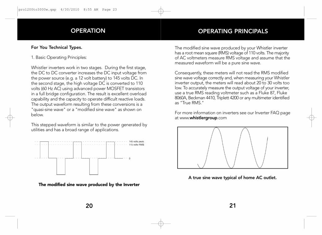
Whistler inverters work in two stages. During the first stage,the DC to DC converter increases the DC input voltage fromthe power source (e.g. a 12 volt battery) to 145 volts DC. Inthe second stage, the high voltage DC is converted to 110volts (60 Hz AC) using advanced power MOSFET transistorsin a full bridge configuration. The result is excellent overloadcapability and the capacity to operate difficult reactive loads.The output waveform resulting from these conversions is a"quasi-sine wave" or a "modified sine wave" as shown onbelow.
This stepped waveform is similar to the power generated byutilities and has a broad range of applications.
The modified sine wave produced by the Inverter
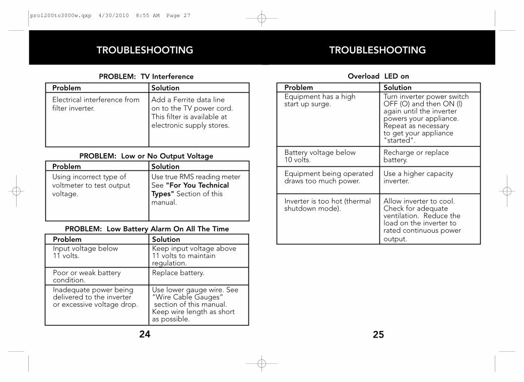
The modified sine wave produced by your Whistler inverterhas a root mean square (RMS) voltage of 110 volts. The majorityof AC voltmeters measure RMS voltage and assume that themeasured waveform will be a pure sine wave.
Consequently, these meters will not read the RMS modifiedsine wave voltage correctly and, when measuring your Whistlerinverter output, the meters will read about 20 to 30 volts toolow. To accurately measure the output voltage of your inverter,use a true RMS reading voltmeter such as a Fluke 87, Fluke8060A, Beckman 4410, Triplett 4200 or any multimeter identifiedas "True RMS."
For more information on inverters see our Inverter FAQ pageat www.whistlergroup.com
A true sine wave typical of home AC outlet.
pro1200to3000w.qxp 4/30/2010 8:55 AM Page 23

OPERATION SUMMARY
• In the event of automatic shut down, turn the inverterOFF (O) immediately. Do not restart the inverter until thesource of the problem has been identified and corrected.
• To avoid battery drain, always disconnect the inverterwhen the vehicle is not in use for long periods.
• Do not expose the inverter to moisture.
• Avoid placing the inverter near sources of heat or indirect sunlight.
• When in use, make certain that the inverter is properlyventilated.
• Do not use the inverter near flammable materials,fumes, or gases.
• Always operate the inverter in accordance with theinstructions in this manual. Failure to do so may resultin property damage, personal injury, or loss of life.
• While connecting the inverter to the power source,make certain that the inverter is well removed fromany potential source of flammable fumes or gases.
• In the event a continuous audible alarm or automaticshut off, turn the inverter OFF immediately. Do notrestart the inverter until the source of the problem hasbeen identified and corrected.
23
OPERATING PRINCIPALS/SUMMARY
In Review.
• Never attempt to operate your Whistler inverter fromany power source other than a 12 volt battery or agroup of batteries that total 12 volts.
• Always make certain that the power cable terminalconnections Negative (-) to Negative (-) and Positive(+) to Positive (+). Check these connections frequently to ensure that they are secure.
• Make certain the rated power consumption of the appliance or equipment you wish to operate is compatiblewith the capacity of your inverter.
• If the rated power consumption of the equipment is inthe range of the maximum specified wattage of yourconverter, test the inverter to ensure that it will operateproperly.
• Before attempting to use a battery charger see page 16.
• Before attempting to use medical equipment see page 6.
• Use the proper gauge cable (smaller the number, thelarger the cable) available to connect the inverter tothe power source.
• When operating the inverter with the engine off, start theengine every 30 to 60 minutes and let it run for at least10 minutes to recharge the battery.
22
pro1200to3000w.qxp 4/30/2010 8:55 AM Page 25
TROUBLESHOOTING
25
PROBLEM: TV Interference
Problem Solution
Electrical interference from Add a Ferrite data linefilter inverter. on to the TV power cord.
This filter is available at electronic supply stores.
PROBLEM: Low or No Output Voltage
Problem Solution
Using incorrect type of Use true RMS reading metervoltmeter to test output See "For You Technical voltage. Types" Section of this
manual.
PROBLEM: Low Battery Alarm On All The Time
Problem SolutionInput voltage below Keep input voltage above 11 volts. 11 volts to maintain
regulation.
Poor or weak battery Replace battery.condition.
Inadequate power being Use lower gauge wire. See delivered to the inverter “Wire Cable Gauges”or excessive voltage drop. section of this manual.
Keep wire length as short as possible.
24
TROUBLESHOOTING
Overload LED on
Problem SolutionEquipment has a high Turn inverter power switchstart up surge. OFF (O) and then ON (l)
again until the inverter powers your appliance. Repeat as necessaryto get your appliance "started".
Battery voltage below Recharge or replace 10 volts. battery.
Equipment being operated Use a higher capacity draws too much power. inverter.
Inverter is too hot (thermal Allow inverter to cool.shutdown mode). Check for adequate
ventilation. Reduce the load on the inverter torated continuous poweroutput.
pro1200to3000w.qxp 4/30/2010 8:55 AM Page 27
SPECIFICATION
Pro-1200W WATT INVERTER SPECIFICATIONSMaximum Continuous Power . . . . . . . . . . . . . . . . . . . .1200 WattsMaximum Surge Capability (Peak Power) . . . . . . . . . .2400 Watts*No Load Current Draw . . . . . . . . . . . . . . . . . . . . . . . . . . . . . .< 1.0AWaveform . . . . . . . . . . . . . . . . . . . . . . . . . . . . .Modified Sine WaveOperating Input Voltage Range . . . . . . . . . . .11-15+0.5 Volts DCAC Receptacle . . . . . . . . . . . . . . .Three North American 3 ProngUSB . . . . . . . . . . . . . . . . . . . . . . . . . . . . . . . . . . .5 Volt 500mA MaxApproximate Dimensions . . . . . . . . . . . .8.9” L x 7.4” W x 3.54” H Approximate Weight . . . . . . . . . . . . . . . . . . . . . . . . . . . . . . .4.5 lbs
Pro-1600W WATT INVERTER SPECIFICATIONSMaximum Continuous Power . . . . . . . . . . . . . . . . . . . .1600 WattsMaximum Surge Capability (Peak Power) . . . . . . . . . .3200 Watts*No Load Current Draw . . . . . . . . . . . . . . . . . . . . . . . . . . . . . .< 1.0AWaveform . . . . . . . . . . . . . . . . . . . . . . . . . . . . .Modified Sine WaveOperating Input Voltage Range . . . . . . . . . . .11-15+0.5 Volts DCAC Receptacle . . . . . . . . . . . . . . .Three North American 3 ProngUSB . . . . . . . . . . . . . . . . . . . . . . . . . . . . . . . . . . .5 Volt 500mA MaxApproximate Dimensions . . . . . . . . . . . .8.9” L x 7.4” W x 3.54” H Approximate Weight . . . . . . . . . . . . . . . . . . . . . . . . . . . . . . .5.4 lbs
Pro-2000W WATT INVERTER SPECIFICATIONSMaximum Continuous Power . . . . . . . . . . . . . . . . . . . .2000 WattsMaximum Surge Capability (Peak Power) . . . . . . . . . .4000 Watts*No Load Current Draw . . . . . . . . . . . . . . . . . . . . . . . . . . . . . .< 1.0AWaveform . . . . . . . . . . . . . . . . . . . . . . . . . . . . .Modified Sine WaveOperating Input Voltage Range . . . . . . . . . . .11-15+0.5 Volts DCAC Receptacle . . . . . . . . . . . . . . .Three North American 3 ProngUSB . . . . . . . . . . . . . . . . . . . . . . . . . . . . . . . . . . .5 Volt 500mA MaxApproximate Dimensions . . . . . . . . . . . .12” L x 8.9” W x 3.54” HApproximate Weight . . . . . . . . . . . . . . . . . . . . . . . . . . . . . . .7.3 lbs
2726
SPECIFICATION
Pro-2500W WATT INVERTER SPECIFICATIONSMaximum Continuous Power . . . . . . . . . . . . . . . . . . . .2500 WattsMaximum Surge Capability (Peak Power) . . . . . . . . . .5000 Watts*No Load Current Draw . . . . . . . . . . . . . . . . . . . . . . . . . . . . . .< 1.2AWaveform . . . . . . . . . . . . . . . . . . . . . . . . . . . . .Modified Sine WaveOperating Input Voltage Range . . . . . . . . . . .11-15+0.5 Volts DCAC Receptacle . . . . . . . . . . . . . . .Three North American 3 ProngUSB . . . . . . . . . . . . . . . . . . . . . . . . . . . . . . . . . . .5 Volt 500mA MaxApproximate Dimensions . . . . . . . . . . . .12” L x 8.9” W x 3.54” H Approximate Weight . . . . . . . . . . . . . . . . . . . . . . . . . . . . . . . .8.7 lb
Pro-3000W WATT INVERTER SPECIFICATIONSMaximum Continuous Power . . . . . . . . . . . . . . . . . . . .3000 WattsMaximum Surge Capability (Peak Power) . . . . . . . . . .6000 Watts*No Load Current Draw . . . . . . . . . . . . . . . . . . . . . . . . . . . . . .< 1.3AWaveform . . . . . . . . . . . . . . . . . . . . . . . . . . . . .Modified Sine WaveOperating Input Voltage Range . . . . . . . . . . .11-15+0.5 Volts DCAC Receptacle . . . . . . . . . . . . . . .Three North American 3 ProngUSB . . . . . . . . . . . . . . . . . . . . . . . . . . . . . . . . . . .5 Volt 500mA MaxApproximate Dimensions . . . . . . . . . . .15.5” L x 8.9” W x 3.54” H Approximate Weight . . . . . . . . . . . . . . . . . . . . . . . . . . . . . . .12.5 lb
*Under certain conditions your inverter may provide up to 2 times thecontinuous rating for a brief period.
pro1200to3000w.qxp 4/30/2010 8:55 AM Page 29

WARRANTY
IMPORTANT: Whistler will not assume responsibility for lossor damage incurred in shipping. Therefore, please ship yourinverter insured with return receipt requested.
2. Include the following clearly printed information:• Your name and street address (for shipping via UPS), a
daytime telephone number, (No P.O. Box please) and an e-mail address (if applicable).
• A detailed description of the problem, i.e. Unit powers up but no AC output.
• A copy of your dated store receipt or bill of sale.
3. Be certain your inverter is returned with its serial number.For reference, please write your unit’s serial number in the following space: s/n __________________.
Inverters without serial numbers are not covered under warranty.
IMPORTANT: To validate that your inverter is within thewarranty period, make sure you keep a copy of your datedstore receipt! You may register your warranty online atwww.whistlergroup.com, however, for warranty verificationpurposes, a copy of your dated store receipt must accompanyany unit sent in for warranty work.
Service Out Of WarrantyInverters will be repaired at “out of warranty” service rates when:• The unit’s original warranty has expired.• A dated store receipt is not supplied.• The unit has been returned without its serial number.• The unit has been abused, modified, installed
improperly, or had its housing removed.29
WARRANTY
Consumer WarrantyThe Whistler Pro series inverters are warranted to the originalpurchaser for a period of (2) two years from the date oforiginal purchase against all defects in materials andworkmanship. This limited warranty is void if the unit isabused, modified, installed improperly, had its housingremoved, or has a missing serial number. There are no expresswarranties covering this product other than those set forth inthis warranty. All express or implied warranties for this product arelimited to (2) two years. Whistler is not liable for damagesarising from the use, misuse, or operation of this product.
Service Under WarrantyDuring the warranty period, defective units will be repaired orreplaced (with the same or a comparable model), at Whistler’soption, without charge to the purchaser when returned witha dated store receipt to the address below. Inverters returnedwithout a dated store receipt will be handled as described insection “Service Out Of Warranty.”
When returning a unit for service, please follow theseinstructions:
1. Ship the inverter in the original carton or in a suitable sturdyequivalent, fully insured, with return receipt requested, andshipping charges prepaid to:
Whistler Repair Dept.551 N. 13th St.Rogers, AR. 72756
Please allow 3 weeks for return.
28
pro1200to3000w.qxp 4/30/2010 8:55 AM Page 31

MEMO
3130
WARRANTY
The out of warranty service fee for the Pro Series inverters areas follows:Pro-1200W inverter is $75.00Pro-1600W inverter is $95.00Pro-2000W inverter is $125.00Pro-2500W inverter is $155.00Pro-3000W inverter is $185.00.
If you require out of warranty service, please return yourinverter as outlined in the section “Service Under Warranty”along with a certified check or money order for the correctamount. Payment may also be made by MasterCard, VISAor American Express; personal checks are not accepted.In the event repairs cannot be covered by the service fee,you will be contacted by a Whistler technical service specialist who will outline options availableto you. If you elect not to have your inverter repaired/replaced,it will be returned to you along with your certified check ormoney order.
IMPORTANT: When returning your inverter for service, becertain to include a daytime telephone number and emailaddress (if applicable).
Customer ServiceIf you have questions concerning the operation of your Whistlerinverter, or require service during or after the warranty period,please call Customer Service at 1-800-531-0004.
Representatives are available to answer your questionsMonday - Friday from 8:00 a.m. to 5:00 p.m. (CT).
pro1200to3000w.qxp 4/30/2010 8:55 AM Page 33