owner's manual -...
TRANSCRIPT
SmartCarve4 Software System
Owner's Manual
SmartCarve4 User Manual Foreword
-1-
Foreword Thanks for purchasing the laser engraving machine control system of our company.
Before operating, please read this manual carefully to ensure proper operation.
Please keep the manual properly for reference.
Since the configs are different, certain models do not have the functions listed in this
manual. Please refer to the specific functions for details.
This user manual is drafted for
Control system designer
Laser cutter operator
SmartCarve4 User Manual Foreword
-1-
Contents
Foreword....................................................................................................................... 1
Chapter 1 Software Introduction ................................................................................... 3
1.1 Software installation ....................................................................................... 3
1.1.1 Installation requirements ......................................................................... 3
1.1.2 Installation ............................................................................................... 4
1.2 Uninstallation .................................................................................................. 6
1.3 Operational flowchart ..................................................................................... 8
Chapter 2 Software Application ..................................................................................... 9
2.1 Software interface ........................................................................................... 9
2.1.1 Menu bar ............................................................................................... 10
2.1.2 System toolbar ....................................................................................... 12
2.1.3 Status bar .............................................................................................. 14
2.1.4 Drawing area ......................................................................................... 14
2.2 Software operation ....................................................................................... 16
2.2.1 Opening and Importing Files .................................................................. 16
2.2.2 Drawing and Attribute Settings .............................................................. 23
2.2.3 Figure editing ......................................................................................... 34
2.2.4 Figure modification ................................................................................ 38
2.2.5 Layer function ........................................................................................ 52
2.2.6 Virtual Print input .................................................................................. 55
2.2.7 File storage ............................................................................................ 60
2.3 Track simulation ............................................................................................ 65
Chapter 3 Carve Out .................................................................................................... 67
3.1 Yueming First Control Card ............................................................................ 67
3.1.1 Output ................................................................................................... 67
3.1.2 Parameter config ................................................................................... 74

SmartCarve4 User Manual Foreword
-2-
3.2 Config of machine with Yueming Third Control Card ...................................... 88
3.2.1 Output ................................................................................................... 88
3.2.2 Parameter config ................................................................................... 89
Chapter 4 Example .................................................................................................... 101
4.1 Take Yueming First Control Card as an example ........................................... 101
4.2 Take Yueming Third Control Card as an example ......................................... 103
4.2.1 Network transmission .......................................................................... 103
4.2.2 Standard model ................................................................................... 104
4.2.3 Feeding model ..................................................................................... 107
4.2.4 Graphics file ......................................................................................... 108
Post ........................................................................................................................... 111

SmartCarve4 User Manual Software Introduction
-3-
Chapter 1 Software Introduction SmartCarve software has the following features:
Figure drawing and editing functions, including the drawing and editing of straight line, rectangle, polygon, circular arc, ellipse, curve, text, etc. node editing is supported, allowing users to adjust the figure precisely in a more convenient way; it also supports the filling and gradient treatment.
Supporting to import figures in plt, dxf, dst, dsb, ai, bmp, jpg, gif, out, ymd, yln, etc. formats; supporting screen dot treatment of bitmap, reverse-color treatment, etc.
Supporting many languages, including Chinese (Simplified), Chinese (Traditional), English, and other languages. Chinese (Simplified), Chinese (Traditional), and English are available for the moment.
Supporting as many as 256 processing layers; Users can set the processing parameters for the different layers and the priority of processing layers according to the requirements of processing.
Providing scale indication, easy to know clearly about the figure size and position
Capable of saving all figures and processing parameters of the current project
Providing several manners of viewing figures, such as zoom in, zoom out, etc.
With YUEMING virtual printer input function.
Supporting many kinds of motion control cards; processing data can be saved as *.out (YUEMING No.1 card) file or *.ymd (YUEMING Yueming Third Control Card) file and downloaded to the machine.
Supporting figure layout and edge layout with dual laser heads.
Supporting as many as 256 times of re-do and canceling operations.
Capable of modifying the starting point and direction of cutting of graphics primitive
Providing layout in array way
Supporting motion track data smoothing
Providing a function to optimize the path of cutting data
With figure track simulation function
1.1 Software installation
1.1.1 Installation requirements
Operating system: Windows98/2000/XP
PC:
CPU: 1G or above
Memory: 512M or above
SmartCarve4 User Manual Software Introduction
-4-
1.1.2 Installation
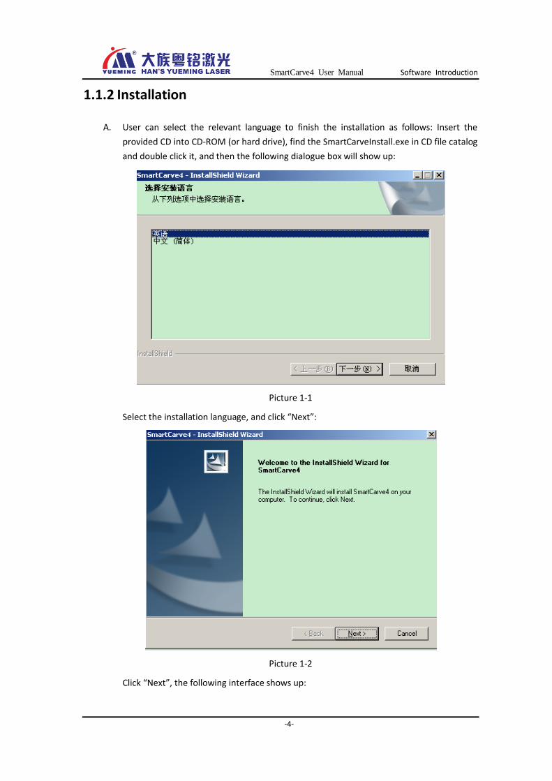
A. User can select the relevant language to finish the installation as follows: Insert the
provided CD into CD-ROM (or hard drive), find the SmartCarveInstall.exe in CD file catalog
and double click it, and then the following dialogue box will show up:
Picture 1-1
Select the installation language, and click “Next”:
Picture 1-2
Click “Next”, the following interface shows up:

SmartCarve4 User Manual Software Introduction
-5-
Picture 1-3
Select “I accept the terms in the license agreement”, and click “Next” to fill in the user name and company name, and then click “Next”:
Select functions that you want to install. User can select all or clear part of these functions before clicking “Next”:

SmartCarve4 User Manual Software Introduction
-6-
Picture 1-5
Finally, click “Install” to install the software:
Picture 1-6
B. After the installation, a shortcut icon of SmartCarve4 will be displayed on the
Windows desktop. User can double click this icon to enter the main interface of this
software.
1.2 Uninstallation
A. Click “Start”-> “All Programs”-> “SmartCarve4”-> “Uninstall”, and a dialogue box shows up:
SmartCarve4 User Manual Software Introduction
-7-
Picture 1-7
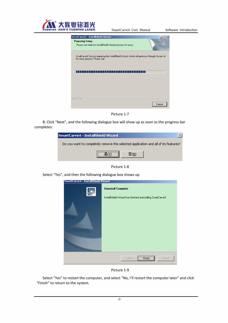
B. Click “Next”, and the following dialogue box will show up as soon as the progress bar completes:
Picture 1-8
Select “Yes”, and then the following dialogue box shows up
Picture 1-9
Select “Yes” to restart the computer, and select “No, I’ll restart the computer later” and click “Finish” to return to the system.

SmartCarve4 User Manual Software Introduction
-8-
1.3 Operational flowchart
Start the software
Create a new working area
Import and edit figure in
working area
Set the processing
property of figure
Yes
Start exporting Wait or stopNO
YES
Operation complete
Satisfy?
YES
NO
Set the type of card
Start printer
input
Start
CorelDRAW
or AUTO
CAD that
supports
printer output
Draw the
pictures
Yueming Vitual
PrintingExport
YES
Export to files
NO
Picture 1-10 Operational flowchart
SmartCarve4 User Manual Software Application
-9-
Chapter 2 Software Application
2.1 Software interface
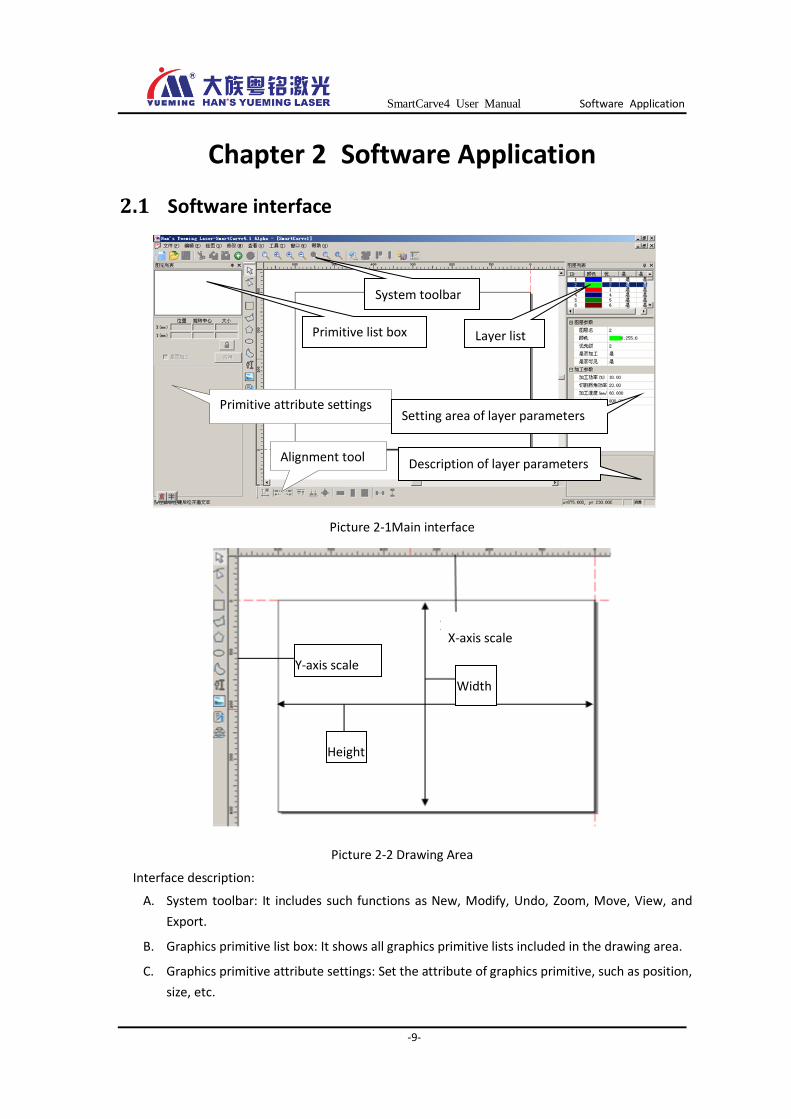
Picture 2-1Main interface
Picture 2-2 Drawing Area
Interface description:
A. System toolbar: It includes such functions as New, Modify, Undo, Zoom, Move, View, and
Export.
B. Graphics primitive list box: It shows all graphics primitive lists included in the drawing area.
C. Graphics primitive attribute settings: Set the attribute of graphics primitive, such as position,
size, etc.
Drawing toolbar
Primitive list box
Primitive attribute settings
Layer list
Setting area of layer parameters
Description of layer parameters
System toolbar
Alignment tool
X-axis scale
Y-axis scale
Height
Width
SmartCarve4 User Manual Software Application
-10-
D. Drawing toolbar: Capable of drawing basic graphics primitive such as straight line,
rectangle, circle, etc. Import of all formats of figure and analog printing are supported.
E. Layer list: It shows 256 layers and the cutting sequence.
F. Setting area of layer parameters: Set the layer parameters and processing parameters.
G. Description of layer parameters: Describe details of all parameters in the layer
H. Alignment tool: When a figure is selected, you can use the tool to arrange the position of
this figure.
I. Drawing area: It is an area for drawing and editing figure.
Note
User can click key on the dialogue box of graphics primitive list or
layer list to hide or display it at any side of the screen.
2.1.1 Menu bar
The menu bar after clicking “New” :
Picture 2-3 Menu bar
2.1.1.1 File (F)
New (Create a new file)
Open (Open a smc project file)
Close (Close the document)
Save (Save the current file as *.smc project file, which is the special data format for this software)
Save as (Save the smc project file)
Import File (Import graphics file of all kinds)
Printer Input (Add the figure designed by other software from printer input to this software)
Import Files to Lib(Import graphics fils to graphics lib )
Carver Out (only available to No. 1 card, engraving output dialogue box)
Export (Save the drafted figure as *.out/*.ymd/*.plt file)
Net Transfer (only available to Yueming Third Control Card, transfer or manage the data and parameters of Yueming Third Control Card via Ethernet)
Exit (close the software)
2.1.1.2 Edit (E)
Undo (Cancel the previous operation and return to the previous state)
Redo (Resume the previous undo operation)

SmartCarve4 User Manual Software Application
-11-
Delete (Delete the selected figure)
Copy (Copy the selected figure)
Paste (Paste the figure that is previously copied or cut)
Cut (Cut the selected figure)
Clone (carry out array copy for the selected figures)
Add to graphic lib(add selected graphic to graphic lib)
Pre Graphe(Select the last graphics primitive)
Next Graphe (Select the next graphics primitive)
2.1.1.3 Draw (D)
Pick(Select the figure)
Edit node(Edit the node of graphics primitive)
Line (Draw a straight line)
Rectangle (Draw a rectangle)
Polygon (Draw a polygon)
Regular polygon (draw a regular polygon)
Ellipse (Draw a circle or an ellipse)
Bézier curve (Draw a Bézier curve)
Text (Draw letters or characters)
Bitmap file (Import image files of different formats such as BMP, JPG, etc.)
Vector file (Import vector files of PLT, DXF, DST, DSB, AI, out, yln, or ymd format)
2.1.1.4 Modify (M)
Mirror (Perform mirror function at X or Y direction on the selected figure)
Fill (Fill in the closed figure)
Coordinate (Set the coordinate system)
Convert line(Transfer the graphics primitive data to curve primitive composed by straight line segment)
Switch (Show or hide the dialogue box of operation)
2.1.1.5 View (V)
Grid (whether to show the background grid in drawing area)
Ruler(whether to show ruler in drawing area)
Layer list (whether to show the interface of figure attribute)
SmartCarve4 User Manual Software Application
-12-
Graphics primitive list (whether to show the interface of graphics primitive attribute)
Graphic library(whether to show the interface of graphic library)
Control panel (whether to show the control panel, only available to PCI card or camera cutting model)
Camera panel (whether to show camera panel, only available to camera cutting or PCI card model)
2.1.1.6 Tools (T)
Language (Many languages are available)
machine (select the card or card type)
machine settings(Set the related system parameters of device according to the selected machine model)
config (config of parameters that are related to software)
2.1.1.7 Window (W)
New window(Create a new window in the current file)
Cascade (Stack up all windows one by one)
Tile horizontally (Place all windows by column)
Tile Vertically (Place all windows by row)
As well as all names of created windows in the software (select as required)
2.1.1.8 Help (H)
Helps(SmartCarve user manual)
About (Software version and copyright statement)
2.1.2 System toolbar
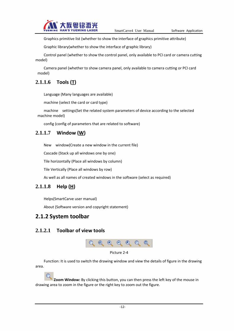
2.1.2.1 Toolbar of view tools
Picture 2-4
Function: It is used to switch the drawing window and view the details of figure in the drawing area.
Zoom Window: By clicking this button, you can then press the left key of the mouse in drawing area to zoom in the figure or the right key to zoom out the figure.
SmartCarve4 User Manual Software Application
-13-
Zoom Pan: You can move the view in the drawing area by clicking this button, or by pressing the middle key of the mouse.
Zoom in: By clicking this button, you can zoom in figure in the drawing area.
Zoom out: By clicking this button, you can zoom out figure in the drawing area.
Zoom all: By clicking this button, you can display all drafted figures in the drawing area.
Zoom Area: Press and hold the left key of mouse to draw a rectangle, and the system will zoom in the selected area.
View workSpace:clicking this button, you can display the entire work area in the drawing area.
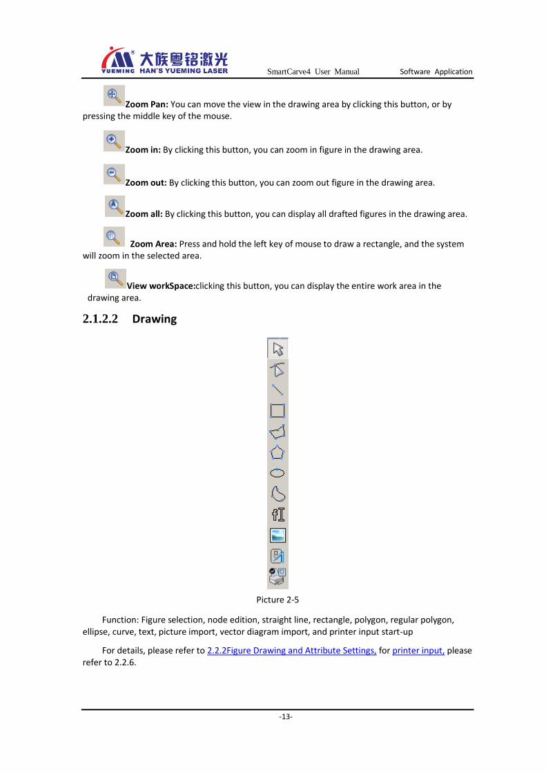
2.1.2.2 Drawing
Picture 2-5
Function: Figure selection, node edition, straight line, rectangle, polygon, regular polygon, ellipse, curve, text, picture import, vector diagram import, and printer input start-up
For details, please refer to 2.2.2Figure Drawing and Attribute Settings, for printer input, please refer to 2.2.6.

SmartCarve4 User Manual Software Application
-14-
2.1.2.3 Arranging
Picture 2-6
Function: Move to origin, left, right, top, bottom, center, set the same width for selected figures, set the same height, set the same size, Distribute rows evenly, and Distribute lines evenly; for details, please refer to 2.7 Arrangement.
2.1.2.4 Other toolbars
Picture 2-7
Function: New, Open, Save, Cut, Copy, Paste
Picture 2-8
Function: Network transmission,(4.2.1) undo some operations (such as cancel the printer input status) (2.2.6), export file (2.2.), engraving output,(3.1.1) Machine setting ( Chapter 3), track simulation (2.3)
2.1.3 Status bar
The bottom position of the software interface:
Picture 2-9
Progress bar: It shows the percentage info of progress when processing data.
Cursor coordinate: It shows the real-time coordinate of cursor. The unit used at X and Y directions is mm.
2.1.4 Drawing area
When you have started the software, click “New” or open a SMC file, the interface of drawing area will be shown as picture 2-2, in which:
X-axis scale: It shows the coordinate and value of X-axis (unit: mm).
Y-axis scale: It shows the coordinate and value of Y-axis (unit: mm).
Cursor coordinate
Progress bar
SmartCarve4 User Manual Software Application
-15-
Origin of coordinates: It is the central coordinate (0, 0) of red cross dashed lines, which the coordinates of X and Y axes are both 0. It usually is the origin of machine. User can set the origin of coordinates in “Coordinate system” (Chapter 2.2.4.3).
Width: Refer to the width of working area, or the working range of machine at X-axis direction
Height: Refer to the height of working area, or the working range of machine at Y-axis direction
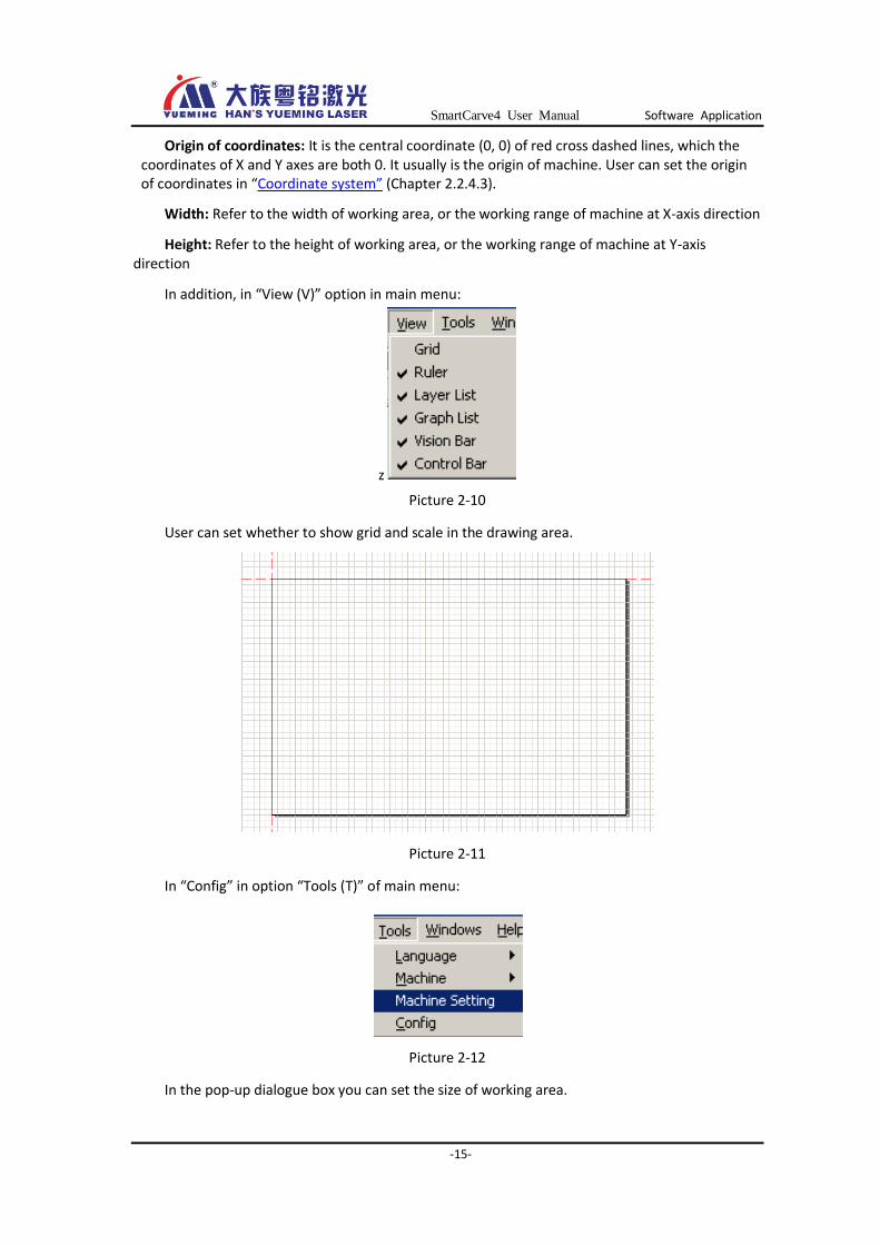
In addition, in “View (V)” option in main menu:
z
Picture 2-10
User can set whether to show grid and scale in the drawing area.
Picture 2-11
In “Config” in option “Tools (T)” of main menu:
Picture 2-12
In the pop-up dialogue box you can set the size of working area.

SmartCarve4 User Manual Software Application
-16-
Picture 2-13
User can regulate the width and height according to the processing scale of carving machine. For example, if the processing scale is 1.3m in width and 0.9m in height, user could fill in 1300 in width and 900 in height in the config dialogue box (unit in mm). The default is 600mm*400mm. Note: The working area set here only affects the display area of drawing.
2.2 Software operation
2.2.1 Opening and Importing Files
This software supports graphics files of many formats. In addition to *.smc of our company, files of bmp, jpg, Plt, dxf, and dst formats are also supported.
2.2.1.1 Opening project files
Project file is in *.smc format. For config of No.1 card, smc file contains the graph data, processing parameters (layer parameters), etc. For config of Yueming Third Control Card, smc file contains the graph data, processing parameters (layer parameters), machine parameters, config parameters, etc. The above data would be overwritten (Save *.smc Chapter2.2.7.1) when user opens the file. Here, it is going to introduce how to open a project file:
A. Open SmartCarve4 and click in the toolbar, the following dialogue box will show up:
SmartCarve4 User Manual Software Application
-17-
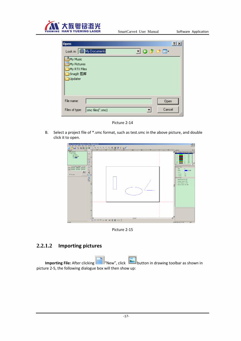
Picture 2-14
B. Select a project file of *.smc format, such as test.smc in the above picture, and double click it to open.
Picture 2-15
2.2.1.2 Importing pictures
Importing File: After clicking “New”, click button in drawing toolbar as shown in picture 2-5, the following dialogue box will then show up:
SmartCarve4 User Manual Software Application
-18-
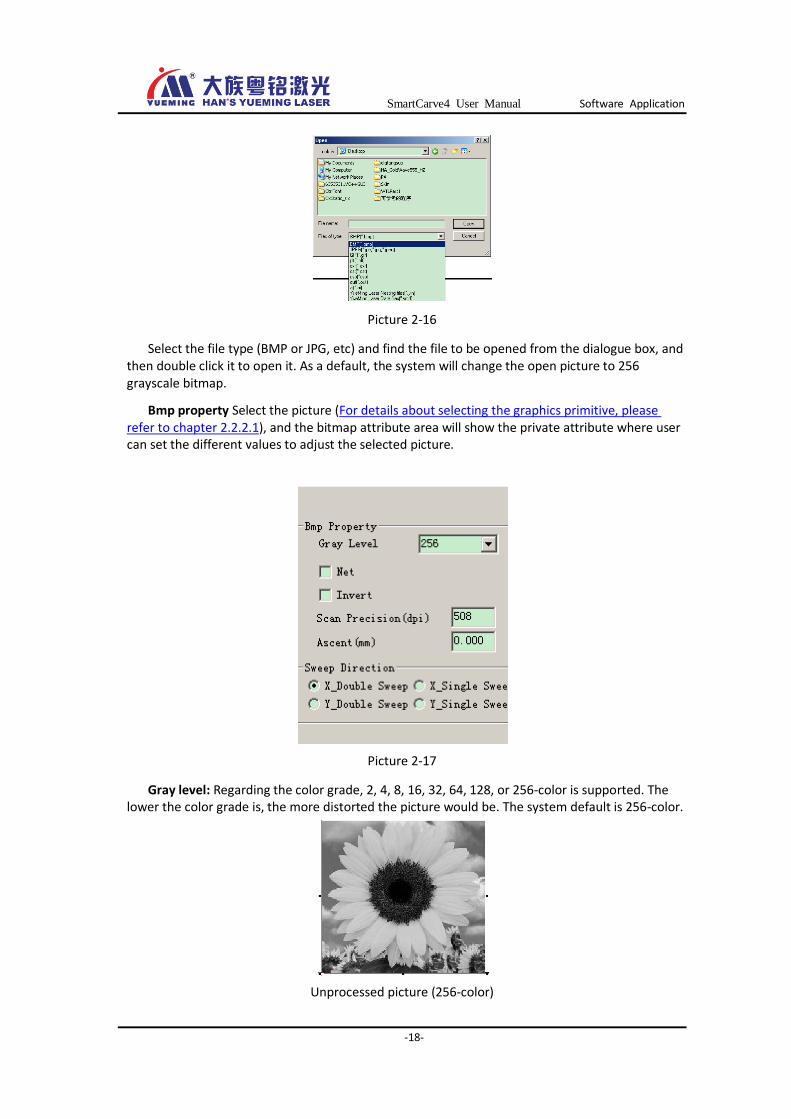
Picture 2-16
Select the file type (BMP or JPG, etc) and find the file to be opened from the dialogue box, and then double click it to open it. As a default, the system will change the open picture to 256 grayscale bitmap.
Bmp property Select the picture (For details about selecting the graphics primitive, please refer to chapter 2.2.2.1), and the bitmap attribute area will show the private attribute where user can set the different values to adjust the selected picture.
Picture 2-17
Gray level: Regarding the color grade, 2, 4, 8, 16, 32, 64, 128, or 256-color is supported. The lower the color grade is, the more distorted the picture would be. The system default is 256-color.
Unprocessed picture (256-color)

SmartCarve4 User Manual Software Application
-19-
16-color 2-color
Picture 2-18
Net : Select this option and click “Apply”, and the picture will be changed to a screen dot picture with only black and white colors as follows:
Before After
Picture 2-19
Invert: Reverse the color of each pixel in the picture. In the picture, the black part is resulting from laser giving out light when the machine is carving, while the white part is because the laser does not give out light.
Before After
Picture 2-20
Scan Precision (dpi): It refers to the breadth between pixels in the picture, unit in DPI and is expressed as line/inch. The smaller the value is set, the bigger the space between lines when scanning would be. The larger the value is set, the closer the space between lines would be. The system default is 1016.
SmartCarve4 User Manual Software Application
-20-
Ascent(mm): If a value is set here, the edge of carved figure would then have gradient. Generally, the gradient is started from the periphery of line. The smaller the value is, the steeper the gradient would be. There is no gradient when the value is 0.
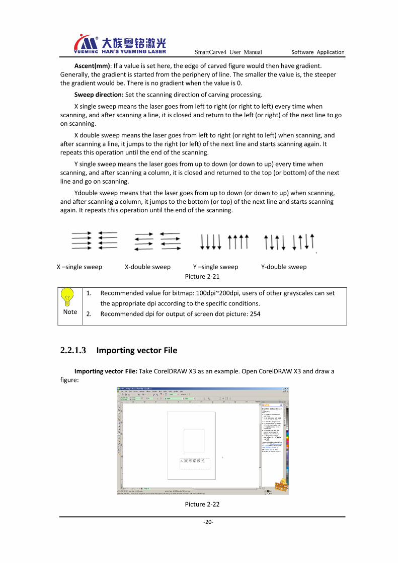
Sweep direction: Set the scanning direction of carving processing.
X single sweep means the laser goes from left to right (or right to left) every time when scanning, and after scanning a line, it is closed and return to the left (or right) of the next line to go on scanning.
X double sweep means the laser goes from left to right (or right to left) when scanning, and after scanning a line, it jumps to the right (or left) of the next line and starts scanning again. It repeats this operation until the end of the scanning.
Y single sweep means the laser goes from up to down (or down to up) every time when scanning, and after scanning a column, it is closed and returned to the top (or bottom) of the next line and go on scanning.
Ydouble sweep means that the laser goes from up to down (or down to up) when scanning, and after scanning a column, it jumps to the bottom (or top) of the next line and starts scanning again. It repeats this operation until the end of the scanning.
X –single sweep X-double sweep Y –single sweep Y-double sweep
Picture 2-21
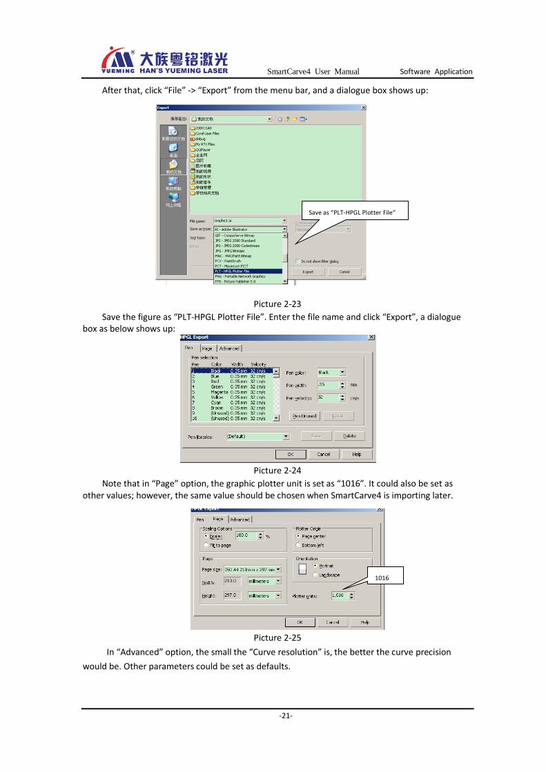
2.2.1.3 Importing vector File
Importing vector File: Take CorelDRAW X3 as an example. Open CorelDRAW X3 and draw a figure:
Picture 2-22
Note
1. Recommended value for bitmap: 100dpi~200dpi, users of other grayscales can set
the appropriate dpi according to the specific conditions.
2. Recommended dpi for output of screen dot picture: 254
SmartCarve4 User Manual Software Application
-21-
After that, click “File” -> “Export” from the menu bar, and a dialogue box shows up:
Picture 2-23
Save the figure as “PLT-HPGL Plotter File”. Enter the file name and click “Export”, a dialogue box as below shows up:
Picture 2-24
Note that in “Page” option, the graphic plotter unit is set as “1016”. It could also be set as other values; however, the same value should be chosen when SmartCarve4 is importing later.
Picture 2-25
In “Advanced” option, the small the “Curve resolution” is, the better the curve precision
would be. Other parameters could be set as defaults.
Save as “PLT-HPGL Plotter File”
1016
SmartCarve4 User Manual Software Application
-22-
Picture 2-26
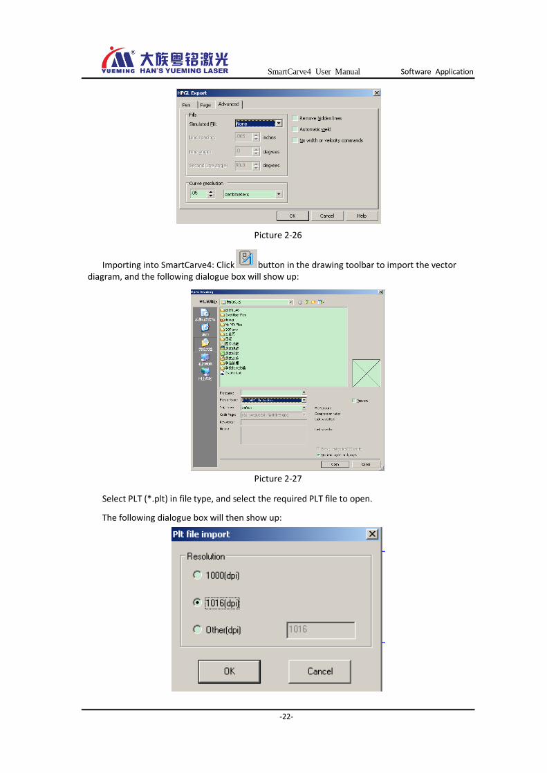
Importing into SmartCarve4: Click button in the drawing toolbar to import the vector diagram, and the following dialogue box will show up:
Picture 2-27
Select PLT (*.plt) in file type, and select the required PLT file to open.
The following dialogue box will then show up:
SmartCarve4 User Manual Software Application
-23-
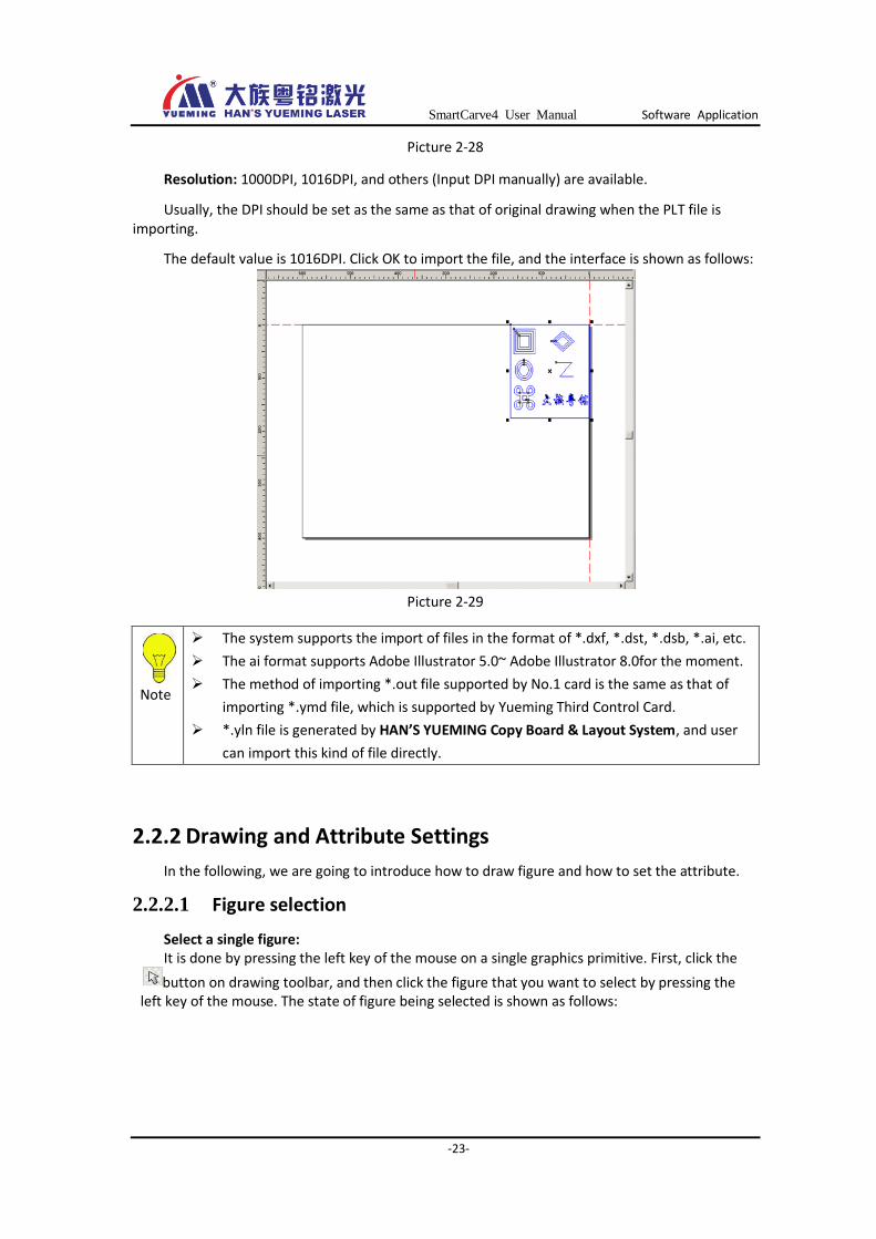
Picture 2-28
Resolution: 1000DPI, 1016DPI, and others (Input DPI manually) are available.
Usually, the DPI should be set as the same as that of original drawing when the PLT file is importing.
The default value is 1016DPI. Click OK to import the file, and the interface is shown as follows:
Picture 2-29
2.2.2 Drawing and Attribute Settings
In the following, we are going to introduce how to draw figure and how to set the attribute.
2.2.2.1 Figure selection
Select a single figure: It is done by pressing the left key of the mouse on a single graphics primitive. First, click the
button on drawing toolbar, and then click the figure that you want to select by pressing the left key of the mouse. The state of figure being selected is shown as follows:
Note
The system supports the import of files in the format of *.dxf, *.dst, *.dsb, *.ai, etc.
The ai format supports Adobe Illustrator 5.0~ Adobe Illustrator 8.0for the moment.
The method of importing *.out file supported by No.1 card is the same as that of
importing *.ymd file, which is supported by Yueming Third Control Card.
*.yln file is generated by HAN’S YUEMING Copy Board & Layout System, and user
can import this kind of file directly.
SmartCarve4 User Manual Software Application
-24-
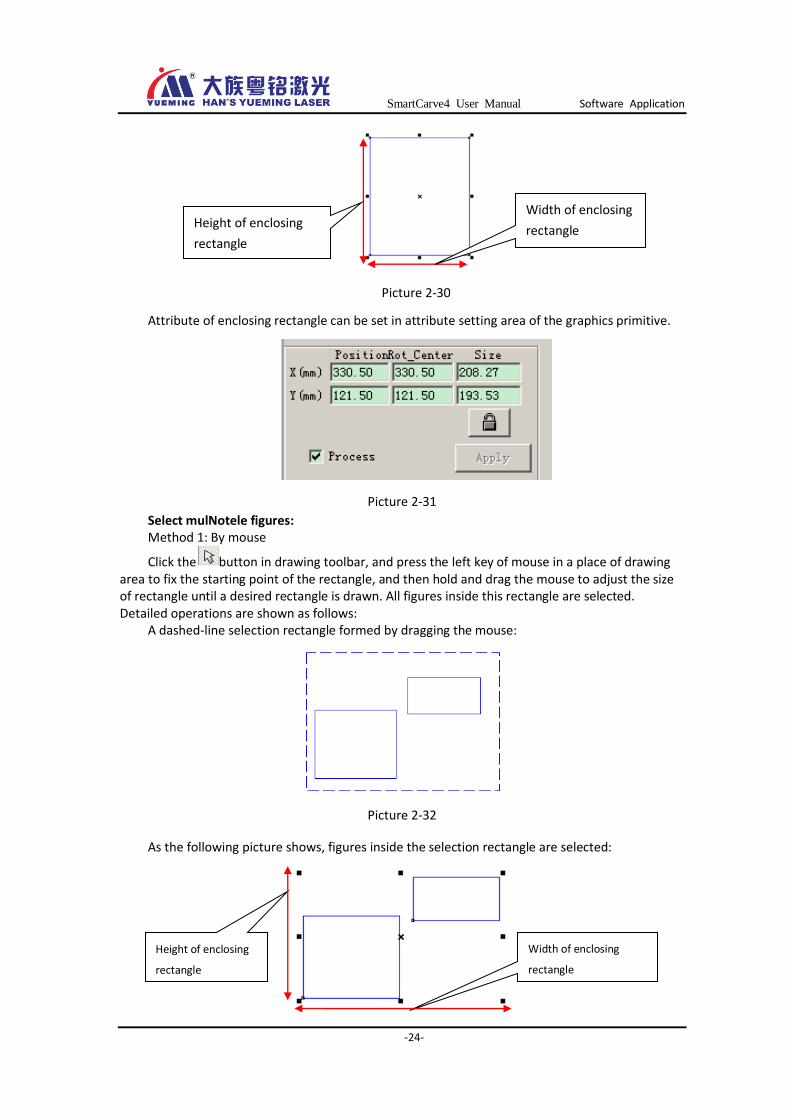
Picture 2-30
Attribute of enclosing rectangle can be set in attribute setting area of the graphics primitive.
Picture 2-31
Select mulNotele figures: Method 1: By mouse
Click the button in drawing toolbar, and press the left key of mouse in a place of drawing area to fix the starting point of the rectangle, and then hold and drag the mouse to adjust the size of rectangle until a desired rectangle is drawn. All figures inside this rectangle are selected. Detailed operations are shown as follows:
A dashed-line selection rectangle formed by dragging the mouse:
Picture 2-32
As the following picture shows, figures inside the selection rectangle are selected:
Height of enclosing
rectangle
Width of enclosing
rectangle
Height of enclosing
rectangle
Width of enclosing
rectangle
SmartCarve4 User Manual Software Application
-25-
Picture 2-33
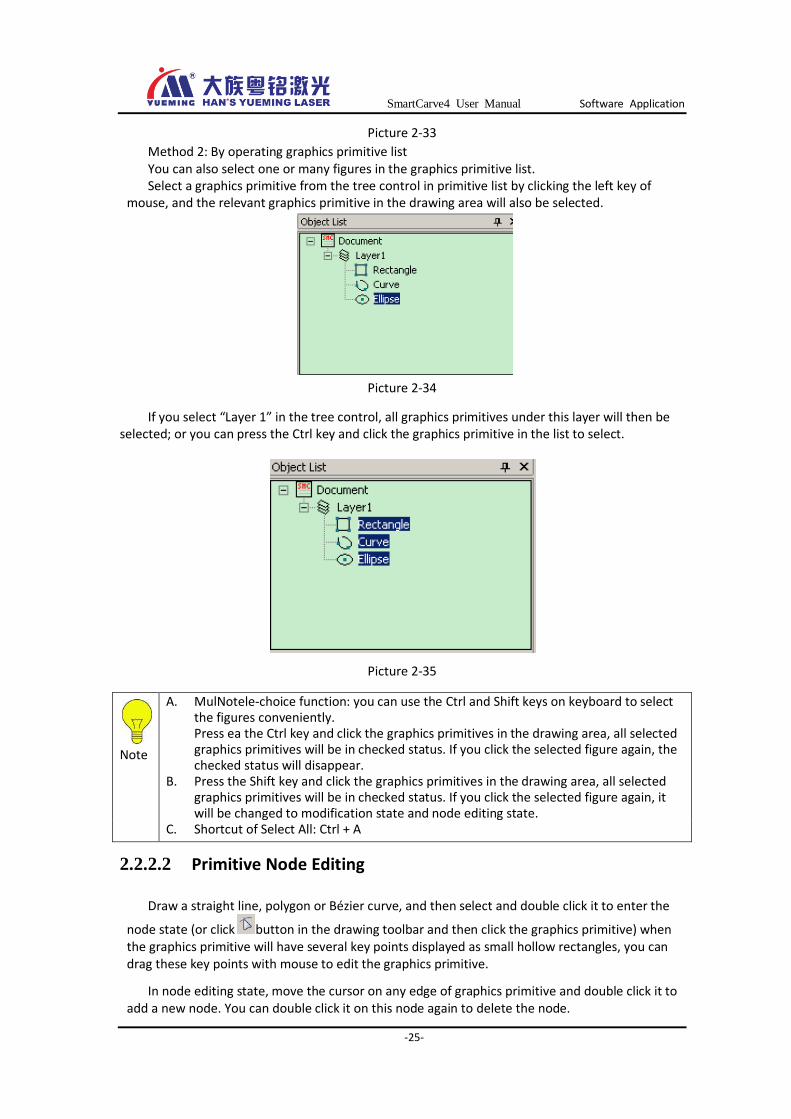
Method 2: By operating graphics primitive list You can also select one or many figures in the graphics primitive list. Select a graphics primitive from the tree control in primitive list by clicking the left key of
mouse, and the relevant graphics primitive in the drawing area will also be selected.
Picture 2-34
If you select “Layer 1” in the tree control, all graphics primitives under this layer will then be selected; or you can press the Ctrl key and click the graphics primitive in the list to select.
Picture 2-35
2.2.2.2 Primitive Node Editing
Draw a straight line, polygon or Bézier curve, and then select and double click it to enter the
node state (or click button in the drawing toolbar and then click the graphics primitive) when the graphics primitive will have several key points displayed as small hollow rectangles, you can drag these key points with mouse to edit the graphics primitive.
In node editing state, move the cursor on any edge of graphics primitive and double click it to add a new node. You can double click it on this node again to delete the node.
Note
A. MulNotele-choice function: you can use the Ctrl and Shift keys on keyboard to select the figures conveniently. Press ea the Ctrl key and click the graphics primitives in the drawing area, all selected graphics primitives will be in checked status. If you click the selected figure again, the checked status will disappear.
B. Press the Shift key and click the graphics primitives in the drawing area, all selected graphics primitives will be in checked status. If you click the selected figure again, it will be changed to modification state and node editing state.
C. Shortcut of Select All: Ctrl + A
SmartCarve4 User Manual Software Application
-26-
Figure is selected Node editing state
Picture 2-36
For regular polygon, it is able to zoom in, zoom out or rotate it by editing the nodes.
For ellipse, it is able to form a section of circular arc by editing the nodes.
2.2.2.3 Straight line
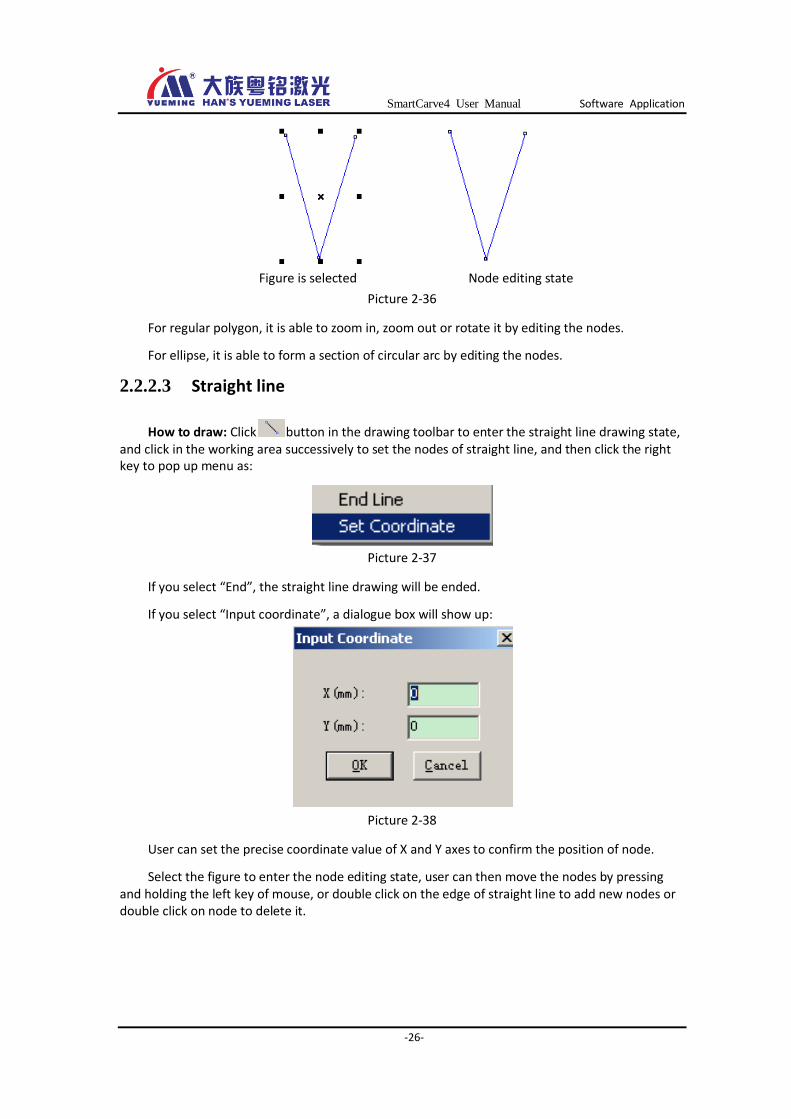
How to draw: Click button in the drawing toolbar to enter the straight line drawing state, and click in the working area successively to set the nodes of straight line, and then click the right key to pop up menu as:
Picture 2-37
If you select “End”, the straight line drawing will be ended.
If you select “Input coordinate”, a dialogue box will show up:
Picture 2-38
User can set the precise coordinate value of X and Y axes to confirm the position of node.
Select the figure to enter the node editing state, user can then move the nodes by pressing and holding the left key of mouse, or double click on the edge of straight line to add new nodes or double click on node to delete it.
SmartCarve4 User Manual Software Application
-27-
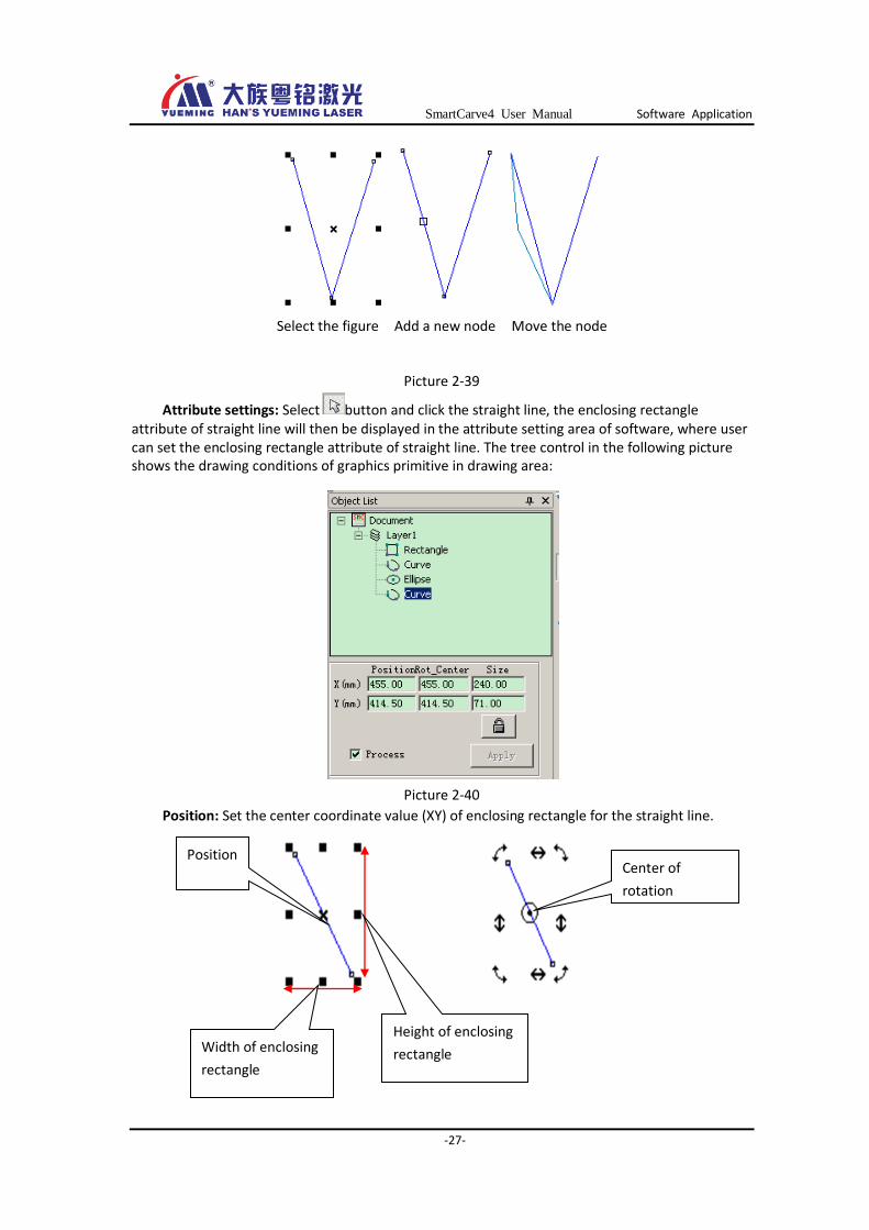
Select the figure Add a new node Move the node
Picture 2-39
Attribute settings: Select button and click the straight line, the enclosing rectangle attribute of straight line will then be displayed in the attribute setting area of software, where user can set the enclosing rectangle attribute of straight line. The tree control in the following picture shows the drawing conditions of graphics primitive in drawing area:
Picture 2-40
Position: Set the center coordinate value (XY) of enclosing rectangle for the straight line.
Center of
rotation
Position
Width of enclosing
rectangle
Height of enclosing
rectangle

SmartCarve4 User Manual Software Application
-28-
Picture 2-41
Center of rotation: Set the center value (XY) when performing the rotation.
Size: Set the size of enclosing rectangle of straight line, which would also influence the size of straight line.
Locking: (unlocking state) means user can edit the graphics primitive; (locking state) means the graphics primitive cannot be edited for the moment.
Whether to process: Tick off this option to engage in processing when exporting engraving cutting; otherwise, it does not engage in the processing.
Apply: Every time when you have modified the attribute, you should click this button to apply the modified parameters.
Note
Press and hold the Ctrl key, the Linking line between two nodes of straight line
will be drafted at 15˚.
2.2.2.4 Rectangle
How to draw: Click button in the drawing toolbar to enter the rectangle drawing state, press and hold the left key of mouse to set one of the endpoints of rectangle in drawing area, and then drag the mouse to adjust the rectangle size until the end of drawing.
Enter the node editing state, select and drag any one of the four nodes to get the rectangular fillet.
Enter the nodeed state Move the nodes
Picture 2-42
Attribute settings: Likewise, select a rectangle, and the rectangle attribute will be displayed in the graphics primitive attribute area, where user can set different values to adjust the selected
Warm
This option only refers to whether the selected graphics primitives engage in processing when exporting engraving cutting. It is different from that mentioned in layer attribute in chapter 2.9, which refers to whether all graphics primitives under the layer engage the processing.
SmartCarve4 User Manual Software Application
-29-
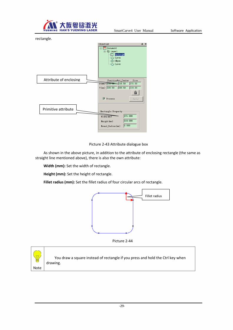
rectangle.
Picture 2-43 Attribute dialogue box
As shown in the above picture, in addition to the attribute of enclosing rectangle (the same as straight line mentioned above), there is also the own attribute:
Width (mm): Set the width of rectangle.
Height (mm): Set the height of rectangle.
Fillet radius (mm): Set the fillet radius of four circular arcs of rectangle.
Picture 2-44
Note
You draw a square instead of rectangle if you press and hold the Ctrl key when drawing.
Fillet radius
Attribute of enclosing
rectangle
Primitive attribute
SmartCarve4 User Manual Software Application
-30-
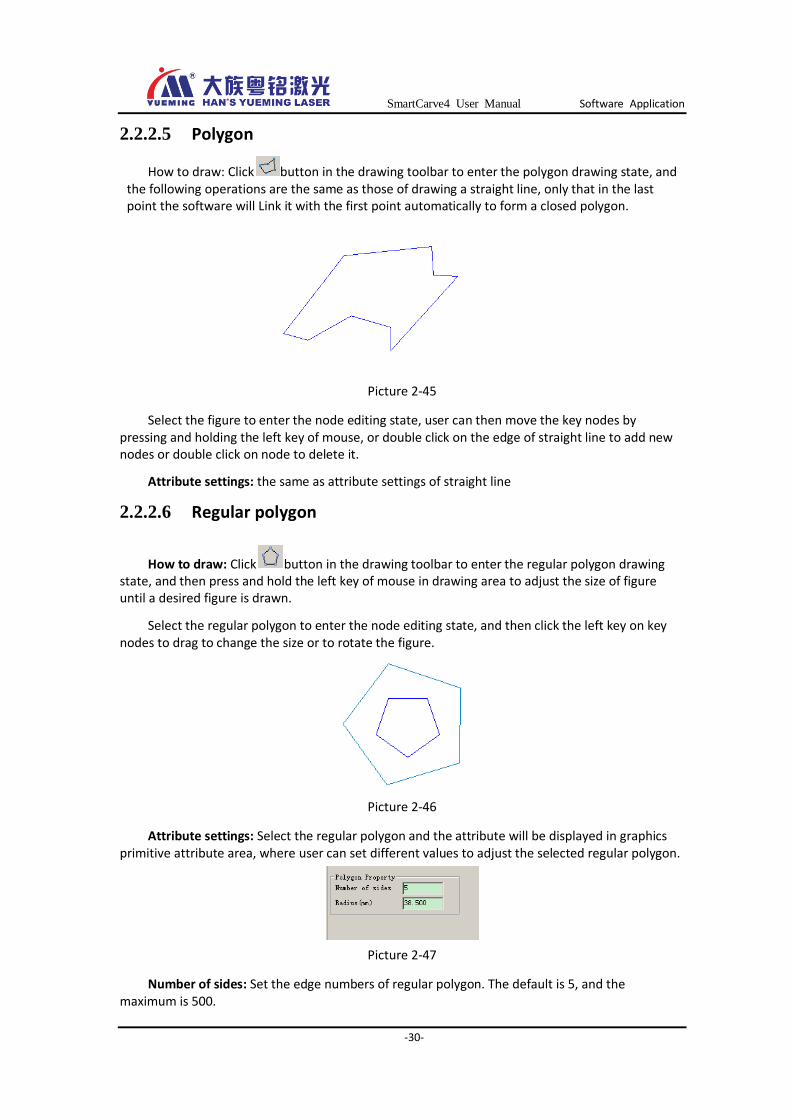
2.2.2.5 Polygon
How to draw: Click button in the drawing toolbar to enter the polygon drawing state, and the following operations are the same as those of drawing a straight line, only that in the last point the software will Link it with the first point automatically to form a closed polygon.
Picture 2-45
Select the figure to enter the node editing state, user can then move the key nodes by pressing and holding the left key of mouse, or double click on the edge of straight line to add new nodes or double click on node to delete it.
Attribute settings: the same as attribute settings of straight line
2.2.2.6 Regular polygon
How to draw: Click button in the drawing toolbar to enter the regular polygon drawing state, and then press and hold the left key of mouse in drawing area to adjust the size of figure until a desired figure is drawn.
Select the regular polygon to enter the node editing state, and then click the left key on key nodes to drag to change the size or to rotate the figure.
Picture 2-46
Attribute settings: Select the regular polygon and the attribute will be displayed in graphics primitive attribute area, where user can set different values to adjust the selected regular polygon.
Picture 2-47
Number of sides: Set the edge numbers of regular polygon. The default is 5, and the maximum is 500.

SmartCarve4 User Manual Software Application
-31-
Radius (mm): Set the distance from the center to each vertex, that is, the radius of circumscribed circle.
2.2.2.7 Ellipse
How to draw: Click button in the drawing toolbar to enter the ellipse drawing state, and then press and hold the left key of mouse in drawing area to adjust the size of figure until a desired figure is drawn.
Select the ellipse to enter the node editing state, and then click the left key on key nodes to drag to adjust the start angle and end angle of ellipse.
Picture 2-48
Attribute settings: Select the ellipse and the attribute will be displayed in primitive attribute area, where user can set different values to adjust the selected ellipse.
Picture 2-49
Start Angle(degree): As shown in the following picture, unit in degree
End Angle(degree): As shown in the following picture, unit in degree
Picture 2-50
Rotate Angle: An angle at which the graphics primitive circles around the center, unit in degree
Long Radius(mm): the major axis of ellipse, as shown in the following picture, unit in mm
End Angle Start Angle
SmartCarve4 User Manual Software Application
-32-
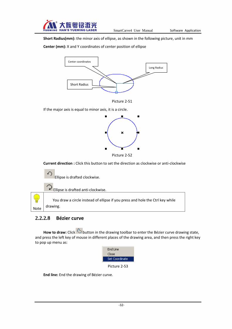
Short Radius(mm): the minor axis of ellipse, as shown in the following picture, unit in mm
Center (mm): X and Y coordinates of center position of ellipse
Picture 2-51
If the major axis is equal to minor axis, it is a circle.
Picture 2-52
Current direction : Click this button to set the direction as clockwise or anti-clockwise
Ellipse is drafted clockwise.
Ellipse is drafted anti-clockwise.
Note
You draw a circle instead of ellipse if you press and hole the Ctrl key while
drawing.
2.2.2.8 Bézier curve
How to draw: Click button in the drawing toolbar to enter the Bézier curve drawing state, and press the left key of mouse in different places of the drawing area, and then press the right key to pop up menu as:
Picture 2-53
End line: End the drawing of Bézier curve.
Center coordinates
Short Radius
Long Radius
SmartCarve4 User Manual Software Application
-33-
Picture 2-54
Close: The last node and the first node of Bézier curve are Linked to form a closed curve.
Set coordinate: Pop up dialogue box, just the same as straight line settings, user can set the precise X and Y coordinates.
Select the graphics primitive to enter the node editing state, click and drag the node to move it. User can double click the left key to add or delete nodes.
Attribute settings: Select the Bézier curve and the attribute will be displayed in primitive attribute area, where user can set different values to adjust the selected Bézier curve.
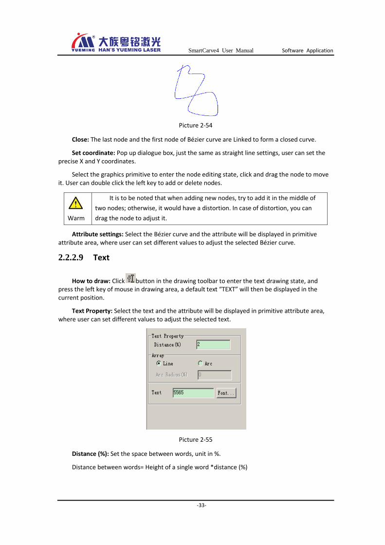
2.2.2.9 Text
How to draw: Click button in the drawing toolbar to enter the text drawing state, and press the left key of mouse in drawing area, a default text “TEXT” will then be displayed in the current position.
Text Property: Select the text and the attribute will be displayed in primitive attribute area, where user can set different values to adjust the selected text.
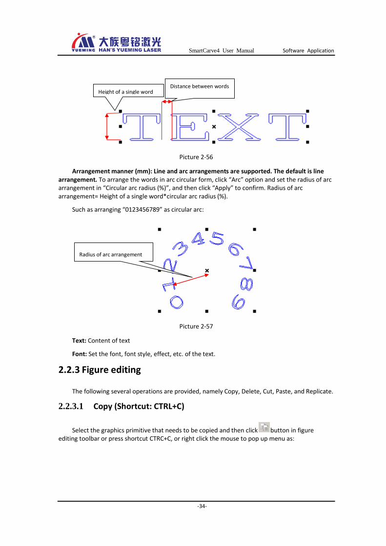
Picture 2-55
Distance (%): Set the space between words, unit in %.
Distance between words= Height of a single word *distance (%)
Warm
It is to be noted that when adding new nodes, try to add it in the middle of
two nodes; otherwise, it would have a distortion. In case of distortion, you can
drag the node to adjust it.
SmartCarve4 User Manual Software Application
-34-
Picture 2-56
Arrangement manner (mm): Line and arc arrangements are supported. The default is line arrangement. To arrange the words in arc circular form, click “Arc” option and set the radius of arc arrangement in “Circular arc radius (%)”, and then click “Apply” to confirm. Radius of arc arrangement= Height of a single word*circular arc radius (%).
Such as arranging “0123456789” as circular arc:
Picture 2-57
Text: Content of text
Font: Set the font, font style, effect, etc. of the text.
2.2.3 Figure editing
The following several operations are provided, namely Copy, Delete, Cut, Paste, and Replicate.
2.2.3.1 Copy (Shortcut: CTRL+C)
Select the graphics primitive that needs to be copied and then click button in figure editing toolbar or press shortcut CTRC+C, or right click the mouse to pop up menu as:
Radius of arc arrangement
Height of a single word Distance between words

SmartCarve4 User Manual Software Application
-35-
Picture 2-58
After pasting, the system will generate a new graphics primitive with the same attribute as original at the same position.
2.2.3.2 Delete (Shortcut: Delete)
Select the graphics primitive that needs to be deleted, and then press the shortcut “Delete” key to delete or right click the mouse to pop up menu as:
Picture 2-59
Click “Delete (D)” to delete.
You can select figures in drawing area or from tree control in graphics primitive list, and press “Delete” key to delete the figures.
2.2.3.3 Cut (Shortcut: CTRT+X)
Select the graphics primitive that needs to be cut, and then press button or the shortcut “CTRC+X” to cut, or right click the mouse to pop up menu as:
Picture 2-60
SmartCarve4 User Manual Software Application
-36-
After pasting, the system will generate a new graphics primitive with the same attribute as original at the same position.
2.2.3.4 Paste (Shortcut: CTRL+V)
After the copy or cut of graphics primitive, you can click button in figure editing toolbar or shortcut CTRL+V to paste the graphics primitive.
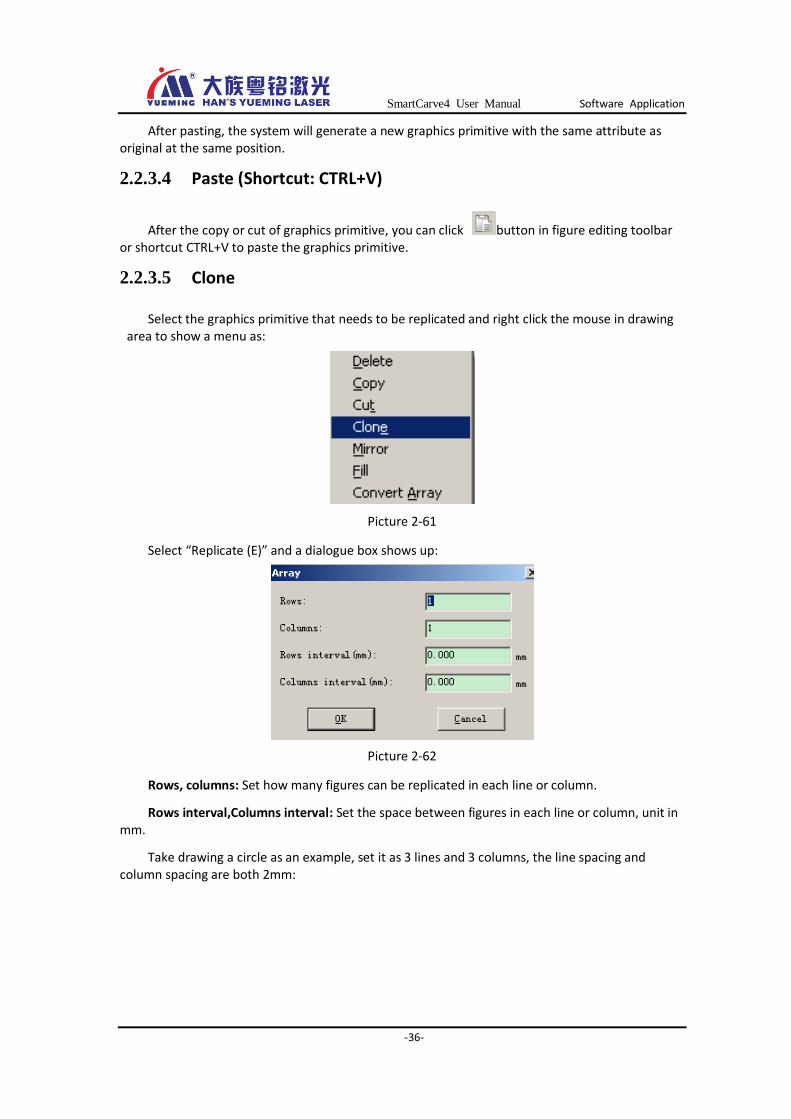
2.2.3.5 Clone
Select the graphics primitive that needs to be replicated and right click the mouse in drawing area to show a menu as:
Picture 2-61
Select “Replicate (E)” and a dialogue box shows up:
Picture 2-62
Rows, columns: Set how many figures can be replicated in each line or column.
Rows interval,Columns interval: Set the space between figures in each line or column, unit in mm.
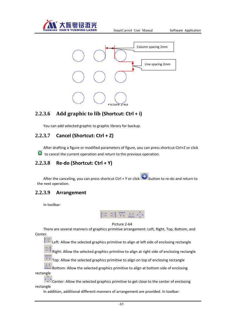
Take drawing a circle as an example, set it as 3 lines and 3 columns, the line spacing and column spacing are both 2mm:
SmartCarve4 User Manual Software Application
-37-
Picture 2-63
2.2.3.6 Add graphic to lib (Shortcut: Ctrl + i)
You can add selected graphic to graphic library for backup.
2.2.3.7 Cancel (Shortcut: Ctrl + Z)
After drafting a figure or modified parameters of figure, you can press shortcut Ctrl+Z or click
to cancel the current operation and return to the previous operation.
2.2.3.8 Re-do (Shortcut: Ctrl + Y)
After the canceling, you can press shortcut Ctrl + Y or click button to re-do and return to the next operation.
2.2.3.9 Arrangement
In toolbar:
Picture 2-64 There are several manners of graphics primitive arrangement: Left, Right, Top, Bottom, and
Center.
Left: Allow the selected graphics primitive to align at left side of enclosing rectangle
Right: Allow the selected graphics primitive to align at right side of enclosing rectangle
Top: Allow the selected graphics primitive to align on top of enclosing rectangle
Bottom: Allow the selected graphics primitive to align at bottom side of enclosing rectangle
Center: Allow the selected graphics primitive to get close to the center of enclosing rectangle
In addition, additional different manners of arrangement are provided. In toolbar:
Column spacing 2mm
Line spacing 2mm
SmartCarve4 User Manual Software Application
-38-
Distribute rows evenly: The selected graphics primitive is horizontally arranged with equal space in the enclosing rectangle.
Distribute lines evenly: The selected graphics primitive is vertically arranged with equal space in the enclosing rectangle.
For example, Distribute rows evenly:
Before After
Picture 2-65
2.2.4 Figure modification
Functions available for the moment include: Mirror, Fill, Coordinate system, Move, Rotate, Transvection, Stretch, and Shift Array, Cutting starting point, and processing direction.
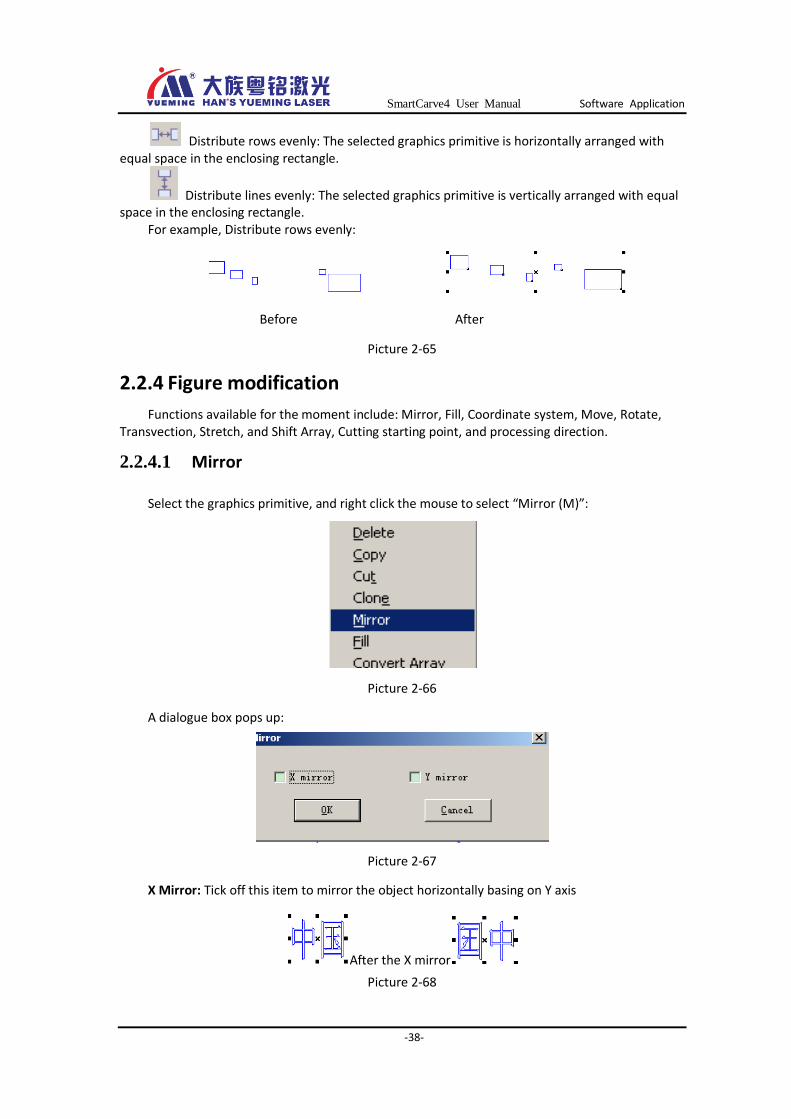
2.2.4.1 Mirror
Select the graphics primitive, and right click the mouse to select “Mirror (M)”:
Picture 2-66
A dialogue box pops up:
Picture 2-67
X Mirror: Tick off this item to mirror the object horizontally basing on Y axis
After the X mirror
Picture 2-68

SmartCarve4 User Manual Software Application
-39-
Y Mirror: Tick off this item to mirror the object vertically basing on X axis
After the Y mirror
Picture 2-69
Note: The above mirror operations are done on the condition that the graphics primitive is selected. If the graphics primitive is not selected, it is mirrored basing on the central line of working area as shown below:
Picture 2-70
2.2.4.2 Fill
Fill in the closed graphics primitive as follows:
A. Draw a graphics primitive that can be filled (closed curve such as rectangle, ellipse, text,
vector diagram, etc.)。
B. Select the graphics primitive and right click the mouse to choose “Fill” from the pop-up menu, and then a dialogue box shows up:
Working area
After
the X
mirro
r
After the Y
mirror
SmartCarve4 User Manual Software Application
-40-
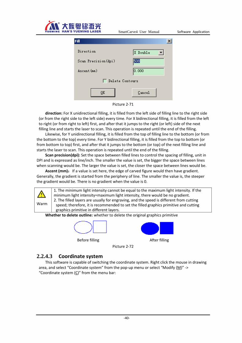
Picture 2-71
direction: For X unidirectional filling, it is filled from the left side of filling line to the right side (or from the right side to the left side) every time. For X bidirectional filling, it is filled from the left to right (or from right to left) first, and after that it jumps to the right (or left) side of the next filling line and starts the laser to scan. This operation is repeated until the end of the filling.
Likewise, for Y unidirectional filling, it is filled from the top of filling line to the bottom (or from the bottom to the top) every time. For Y bidirectional filling, it is filled from the top to bottom (or from bottom to top) first, and after that it jumps to the bottom (or top) of the next filling line and starts the laser to scan. This operation is repeated until the end of the filling.
Scan precision(dpi): Set the space between filled lines to control the spacing of filling, unit in DPI and is expressed as line/inch. The smaller the value is set, the bigger the space between lines when scanning would be. The larger the value is set, the closer the space between lines would be.
Ascent (mm):If a value is set here, the edge of carved figure would then have gradient. Generally, the gradient is started from the periphery of line. The smaller the value is, the steeper the gradient would be. There is no gradient when the value is 0.
Whether to delete outline: whether to delete the original graphics primitive
Before filling After filling
Picture 2-72
2.2.4.3 Coordinate system This software is capable of switching the coordinate system. Right click the mouse in drawing
area, and select “Coordinate system” from the pop-up menu or select “Modify (M)” -> “Coordinate system (C)” from the menu bar:
Warm
1. The minimum light intensity cannot be equal to the maximum light intensity. If the minimum light intensity=maximum light intensity, there would be no gradient. 2. The filled layers are usually for engraving, and the speed is different from cutting
speed; therefore, it is recommended to set the filled graphics primitive and cutting graphics primitive in different layers.
SmartCarve4 User Manual Software Application
-41-
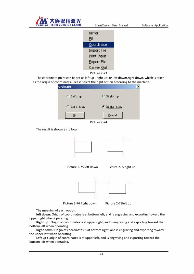
Picture 2-73
The coordinate point can be set as left up , right up, or left dowm,right down, which is taken as the origin of coordinates. Please select the right option according to the machine.
Picture 2-74
The result is shown as follows:
Picture 2-75 left down
Picture 2-77right up
Picture 2-76 Right down Picture 2-78left up
The meaning of each option: left down: Origin of coordinates is at bottom left, and is engraving and exporting toward the
upper right when operating. Right up : Origin of coordinates is at upper right, and is engraving and exporting toward the
bottom left when operating. Right down: Origin of coordinates is at bottom right, and is engraving and exporting toward
the upper left when operating. Left up : Origin of coordinates is at upper left, and is engraving and exporting toward the
bottom left when operating.

SmartCarve4 User Manual Software Application
-42-
For example: Origin of a machine is at upper right, click “Upper right” in the dialogue box of coordinate system, and the interface will display the coordinate system as shown in Picture 2-77.
The following is the figured diagram of machine (top view); the origin of machine is corresponding to the origin of coordinates at the upper right.
2.2.4.4 Move This can be done by mouse, or by setting the parameters in switching dialogue box. The software allows users to use mouse to modify the figure directly. It is convenient and
quick to operate. Draw a graphics primitive, such as rectangle, and select it, and then the following interface shows up:
Picture 2-79
Move the cursor to cross mark in the center of rectangle when it will become a cross arrow
sign , press and hold the left ky to move the figure.
One-key move to origin of coordinates is provided. Select the figure and click button in thetoolbar, the selected figure will be moved to the origin of coordinates in the drawing area.
Select the figure Move to origin
Picture 2-80
Click “Modify” ->“Switch” in the menu bar, and a dialogue box will show up as follows:
Size of working
area Current position of laser
head
Origin of machine
SmartCarve4 User Manual Software Application
-43-
Picture 2-81
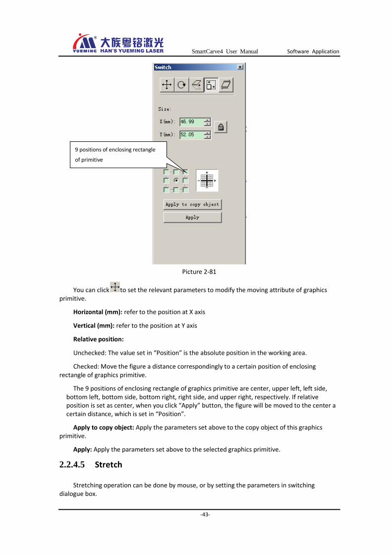
You can click to set the relevant parameters to modify the moving attribute of graphics primitive.
Horizontal (mm): refer to the position at X axis
Vertical (mm): refer to the position at Y axis
Relative position:
Unchecked: The value set in “Position” is the absolute position in the working area.
Checked: Move the figure a distance correspondingly to a certain position of enclosing rectangle of graphics primitive.
The 9 positions of enclosing rectangle of graphics primitive are center, upper left, left side, bottom left, bottom side, bottom right, right side, and upper right, respectively. If relative position is set as center, when you click “Apply” button, the figure will be moved to the center a certain distance, which is set in “Position”.
Apply to copy object: Apply the parameters set above to the copy object of this graphics primitive.
Apply: Apply the parameters set above to the selected graphics primitive.
2.2.4.5 Stretch
Stretching operation can be done by mouse, or by setting the parameters in switching dialogue box.
9 positions of enclosing rectangle
of primitive
SmartCarve4 User Manual Software Application
-44-
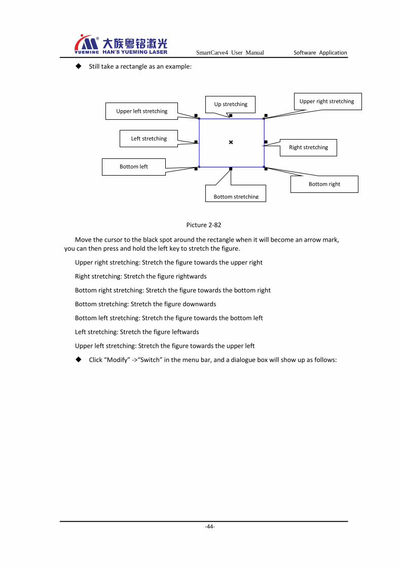
Still take a rectangle as an example:
Picture 2-82
Move the cursor to the black spot around the rectangle when it will become an arrow mark, you can then press and hold the left key to stretch the figure.
Upper right stretching: Stretch the figure towards the upper right
Right stretching: Stretch the figure rightwards
Bottom right stretching: Stretch the figure towards the bottom right
Bottom stretching: Stretch the figure downwards
Bottom left stretching: Stretch the figure towards the bottom left
Left stretching: Stretch the figure leftwards
Upper left stretching: Stretch the figure towards the upper left
Click “Modify” ->“Switch” in the menu bar, and a dialogue box will show up as follows:
Up stretching
Upper left stretching
Left stretching
Bottom left
stretching
Bottom stretching
Bottom right
stretching
Right stretching
Upper right stretching
SmartCarve4 User Manual Software Application
-45-
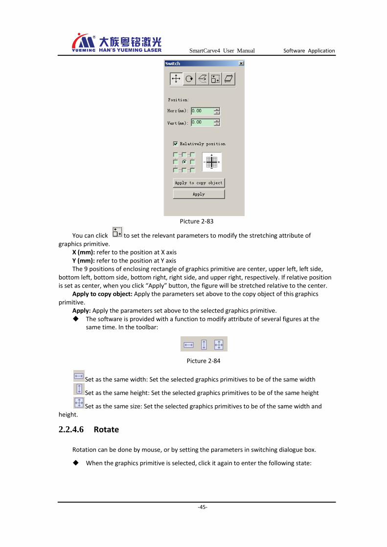
Picture 2-83
You can click to set the relevant parameters to modify the stretching attribute of graphics primitive.
X (mm): refer to the position at X axis Y (mm): refer to the position at Y axis The 9 positions of enclosing rectangle of graphics primitive are center, upper left, left side,
bottom left, bottom side, bottom right, right side, and upper right, respectively. If relative position is set as center, when you click “Apply” button, the figure will be stretched relative to the center.
Apply to copy object: Apply the parameters set above to the copy object of this graphics primitive.
Apply: Apply the parameters set above to the selected graphics primitive. The software is provided with a function to modify attribute of several figures at the
same time. In the toolbar:
Picture 2-84
Set as the same width: Set the selected graphics primitives to be of the same width
Set as the same height: Set the selected graphics primitives to be of the same height
Set as the same size: Set the selected graphics primitives to be of the same width and height.
2.2.4.6 Rotate
Rotation can be done by mouse, or by setting the parameters in switching dialogue box.
When the graphics primitive is selected, click it again to enter the following state:
SmartCarve4 User Manual Software Application
-46-
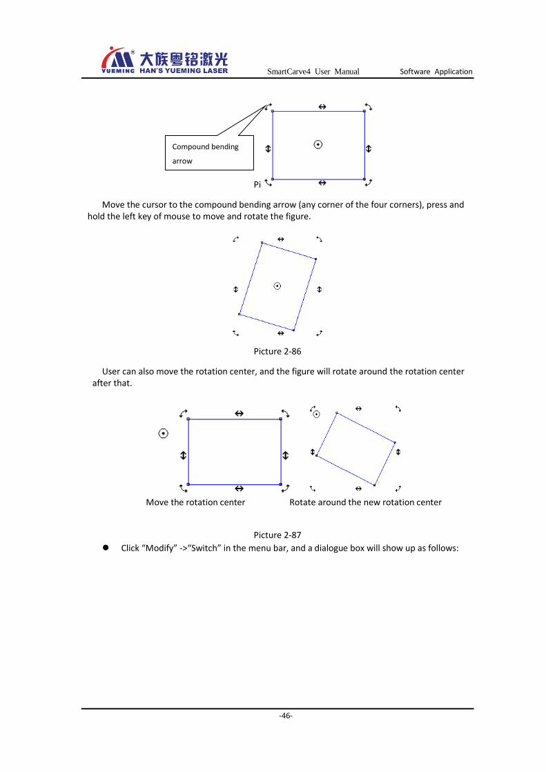
Picture 2-85
Move the cursor to the compound bending arrow (any corner of the four corners), press and hold the left key of mouse to move and rotate the figure.
Picture 2-86
User can also move the rotation center, and the figure will rotate around the rotation center after that.
Move the rotation center Rotate around the new rotation center
Picture 2-87
Click “Modify” ->“Switch” in the menu bar, and a dialogue box will show up as follows:
Compound bending
arrow
SmartCarve4 User Manual Software Application
-47-
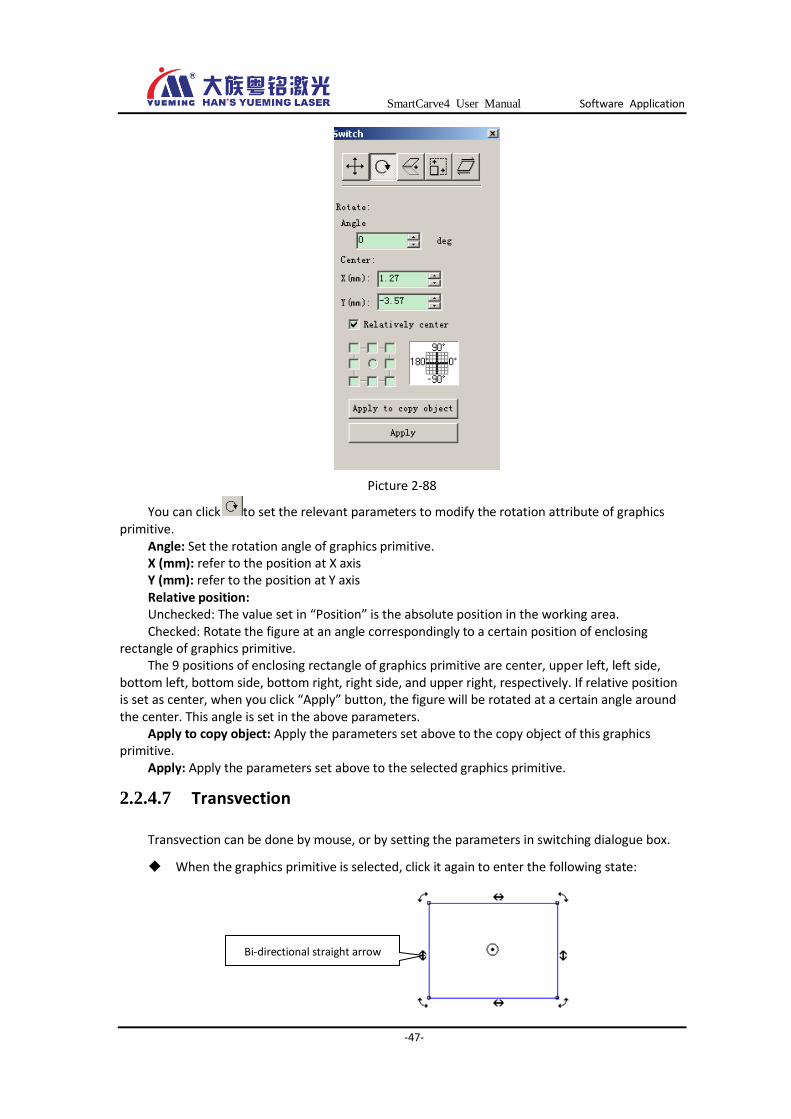
Picture 2-88
You can click to set the relevant parameters to modify the rotation attribute of graphics primitive.
Angle: Set the rotation angle of graphics primitive. X (mm): refer to the position at X axis Y (mm): refer to the position at Y axis Relative position: Unchecked: The value set in “Position” is the absolute position in the working area. Checked: Rotate the figure at an angle correspondingly to a certain position of enclosing
rectangle of graphics primitive. The 9 positions of enclosing rectangle of graphics primitive are center, upper left, left side,
bottom left, bottom side, bottom right, right side, and upper right, respectively. If relative position is set as center, when you click “Apply” button, the figure will be rotated at a certain angle around the center. This angle is set in the above parameters.
Apply to copy object: Apply the parameters set above to the copy object of this graphics primitive.
Apply: Apply the parameters set above to the selected graphics primitive.
2.2.4.7 Transvection
Transvection can be done by mouse, or by setting the parameters in switching dialogue box.
When the graphics primitive is selected, click it again to enter the following state:
Bi-directional straight arrow
SmartCarve4 User Manual Software Application
-48-
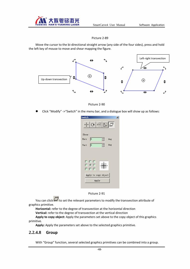
Picture 2-89
Move the cursor to the bi-directional straight arrow (any side of the four sides), press and hold the left key of mouse to move and shear mapping the figure.
Picture 2-90
Click “Modify” ->“Switch” in the menu bar, and a dialogue box will show up as follows:
Picture 2-91
You can click to set the relevant parameters to modify the transvection attribute of graphics primitive.
Horizontal: refer to the degree of transvection at the horizontal direction Vertical: refer to the degree of transvection at the vertical direction Apply to copy object: Apply the parameters set above to the copy object of this graphics
primitive. Apply: Apply the parameters set above to the selected graphics primitive.
2.2.4.8 Group
With “Group” function, several selected graphics primitives can be combined into a group.
Left-right transvection
Up-down transvection
SmartCarve4 User Manual Software Application
-49-
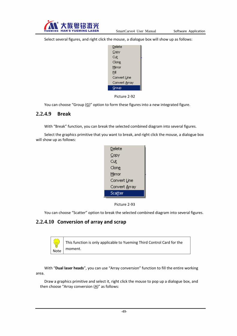
Select several figures, and right click the mouse, a dialogue box will show up as follows:
Picture 2-92
You can choose “Group (G)” option to form these figures into a new integrated figure.
2.2.4.9 Break
With “Break” function, you can break the selected combined diagram into several figures.
Select the graphics primitive that you want to break, and right click the mouse, a dialogue box will show up as follows:
Picture 2-93
You can choose “Scatter” option to break the selected combined diagram into several figures.
2.2.4.10 Conversion of array and scrap
Note
This function is only applicable to Yueming Third Control Card for the
moment.
With “Dual laser heads”, you can use “Array conversion” function to fill the entire working area.
Draw a graphics primitive and select it, right click the mouse to pop up a dialogue box, and then choose “Array conversion (A)” as follows:

SmartCarve4 User Manual Software Application
-50-
Before the array conversion After the array conversion
Picture 2-94
In addition, you can set the line numbers, column numbers, line spacing, and column spacing in the left array settings. As shown in the following picture:
Picture 2-95
After the array conversion, the figures may not fully fill the area due to the working area of machine, that is, there is still blank in the left side of working area. To take advantage of this area, you can add graphics primitives in the blank, and then select them and right click the mouse to convert them into scrap:
Scrap Figures in array

SmartCarve4 User Manual Software Application
-51-
Picture 2-96
2.2.4.11 Convert to line Convert the selected figure into line: The cutting starting point and processing direction can
be changed only when the figure has been converted to line.
Picture 2-97
2.2.4.12 Cutting starting point and processing direction
The cutting starting point and processing direction of graphics primitive can be set via software. For example, draw a graphics primitive and select in menu bar “Modify (M)”-> “Convert to line”:
Picture 2-98
After that, select and double click the graphics primitive, a red arrow will show up, indicating the cutting starting point and the cutting direction:

SmartCarve4 User Manual Software Application
-52-
Picture 2-99
You can right click the mouse at the red arrow to set the reversal processing, or on the other nodes to set the starting point of cutting, while the following menu will show up:
Picture 2-100
After the settings, the figure is as follows:
Reverse Set starting point in other nodes
Picture 2-101
2.2.5 Layer function
Picture 2-102 Interface of layer list box
SmartCarve4 User Manual Software Application
-53-
Layer can be taken as a kind of processing technology. A layer is equivalent to a processing technology. There are several kinds of processing parameters in a layer.
For example in a figure, some places need to be cut deeper and some places need to be cut shallower, this can be done easily with the help of layer settings.
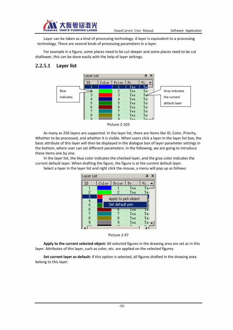
2.2.5.1 Layer list
Picture 2-103
As many as 256 layers are supported. In the layer list, there are items like ID, Color, Priority, Whether to be processed, and whether it is visible. When users click a layer in the layer list box, the basic attribute of this layer will then be displayed in the dialogue box of layer parameter settings in the bottom, where user can set different parameters. In the following, we are going to introduce these items one by one.
In the layer list, the blue color indicates the checked layer, and the gray color indicates the current default layer. When drafting the figure, the figure is at the current default layer.
Select a layer in the layer list and right click the mouse, a menu will pop up as follows:
Picture 2-97
Apply to the current selected object: All selected figures in the drawing area are set as in this layer. Attributes of this layer, such as color, etc. are applied on the selected figures.
Set current layer as default: If this option is selected, all figures drafted in the drawing area belong to this layer.
Blue
indicates
the checked
layer
Gray indicates
the current
default layer
SmartCarve4 User Manual Software Application
-54-
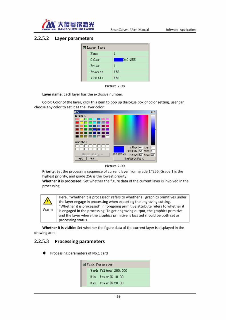
2.2.5.2 Layer parameters
Picture 2-98
Layer name: Each layer has the exclusive number.
Color: Color of the layer, click this item to pop up dialogue box of color setting, user can choose any color to set it as the layer color:
Picture 2-99
Priority: Set the processing sequence of current layer from grade 1~256. Grade 1 is the highest priority, and grade 256 is the lowest priority. Whether it is processed: Set whether the figure data of the current layer is involved in the processing
Whether it is visible: Set whether the figure data of the current layer is displayed in the drawing area
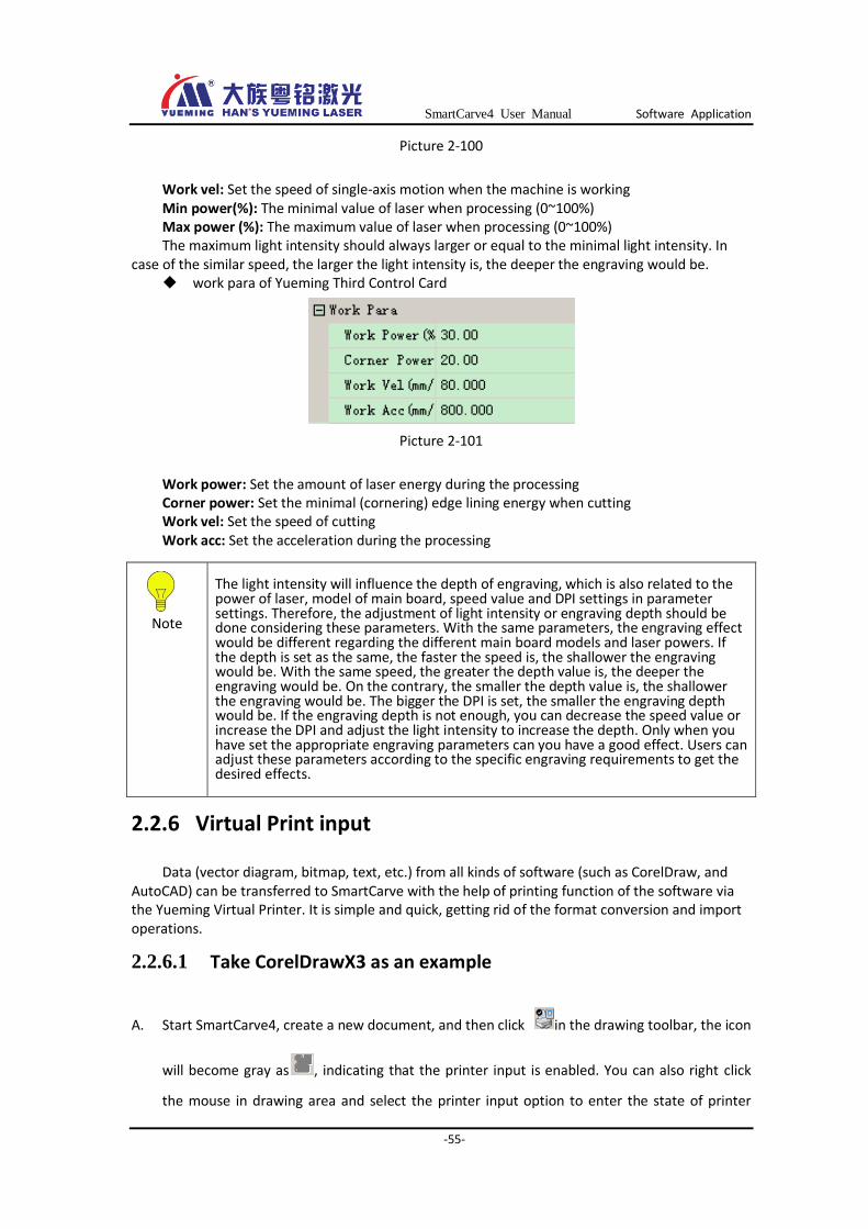
2.2.5.3 Processing parameters
Processing parameters of No.1 card
Warm
Here, “Whether it is processed” refers to whether all graphics primitives under the layer engage in processing when exporting the engraving cutting. “Whether it is processed” in foregoing primitive attribute refers to whether it is engaged in the processing. To get engraving output, the graphics primitive and the layer where the graphics primitive is located should be both set as processing status.
SmartCarve4 User Manual Software Application
-55-
Picture 2-100
Work vel: Set the speed of single-axis motion when the machine is working Min power(%): The minimal value of laser when processing (0~100%) Max power (%): The maximum value of laser when processing (0~100%) The maximum light intensity should always larger or equal to the minimal light intensity. In
case of the similar speed, the larger the light intensity is, the deeper the engraving would be. work para of Yueming Third Control Card
Picture 2-101
Work power: Set the amount of laser energy during the processing Corner power: Set the minimal (cornering) edge lining energy when cutting Work vel: Set the speed of cutting Work acc: Set the acceleration during the processing
2.2.6 Virtual Print input
Data (vector diagram, bitmap, text, etc.) from all kinds of software (such as CorelDraw, and AutoCAD) can be transferred to SmartCarve with the help of printing function of the software via the Yueming Virtual Printer. It is simple and quick, getting rid of the format conversion and import operations.
2.2.6.1 Take CorelDrawX3 as an example
A. Start SmartCarve4, create a new document, and then click in the drawing toolbar, the icon
will become gray as , indicating that the printer input is enabled. You can also right click
the mouse in drawing area and select the printer input option to enter the state of printer
Note
The light intensity will influence the depth of engraving, which is also related to the power of laser, model of main board, speed value and DPI settings in parameter settings. Therefore, the adjustment of light intensity or engraving depth should be done considering these parameters. With the same parameters, the engraving effect would be different regarding the different main board models and laser powers. If the depth is set as the same, the faster the speed is, the shallower the engraving would be. With the same speed, the greater the depth value is, the deeper the engraving would be. On the contrary, the smaller the depth value is, the shallower the engraving would be. The bigger the DPI is set, the smaller the engraving depth would be. If the engraving depth is not enough, you can decrease the speed value or increase the DPI and adjust the light intensity to increase the depth. Only when you have set the appropriate engraving parameters can you have a good effect. Users can adjust these parameters according to the specific engraving requirements to get the desired effects.

SmartCarve4 User Manual Software Application
-56-
input. To cancel the printer input state, you can click in the toolbar.
B. Start CorelDrawX3, draw a figure or import a figure:
Picture 2-102
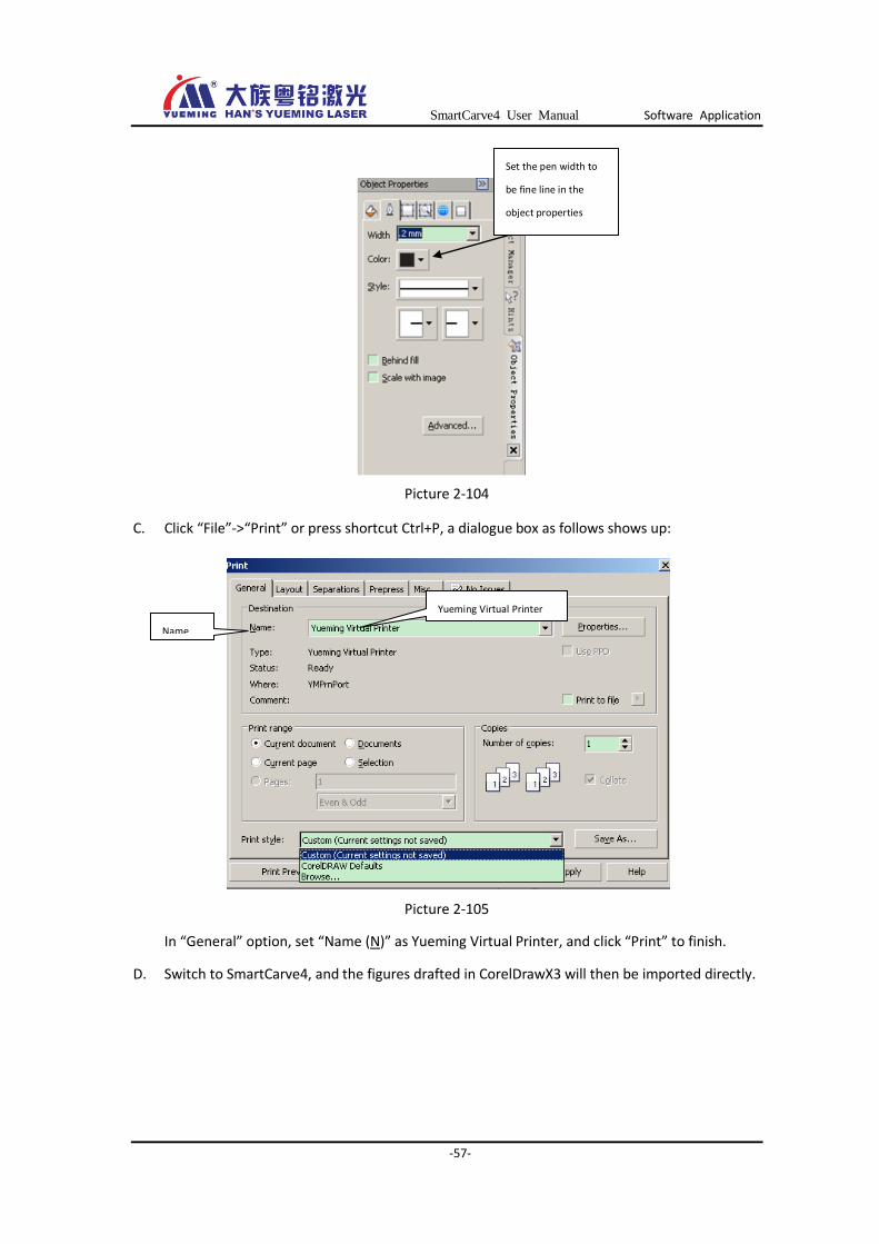
Select “Attribute Manager” from "Edit (E)” in the menu bar and the object attribute page will show up:
Picture 2-103
SmartCarve4 User Manual Software Application
-57-
Picture 2-104
C. Click “File”->“Print” or press shortcut Ctrl+P, a dialogue box as follows shows up:
Picture 2-105
In “General” option, set “Name (N)” as Yueming Virtual Printer, and click “Print” to finish.
D. Switch to SmartCarve4, and the figures drafted in CorelDrawX3 will then be imported directly.
Set the pen width to
be fine line in the
object properties
Yueming Virtual Printer
Name
SmartCarve4 User Manual Software Application
-58-
Picture 2-106
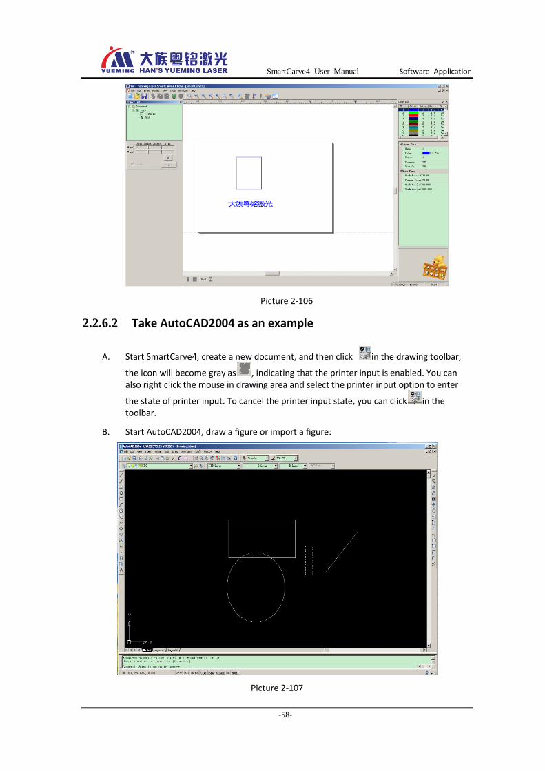
2.2.6.2 Take AutoCAD2004 as an example
A. Start SmartCarve4, create a new document, and then click in the drawing toolbar,
the icon will become gray as , indicating that the printer input is enabled. You can also right click the mouse in drawing area and select the printer input option to enter
the state of printer input. To cancel the printer input state, you can click in the toolbar.
B. Start AutoCAD2004, draw a figure or import a figure:
Picture 2-107

SmartCarve4 User Manual Software Application
-59-
C. Click “File”->“Plot” or press shortcut Ctrl+P, a dialogue box as follows shows up
Picture 2-108
Picture 2-109
Select item “Printing device” and change the “Name (N) in “Printer config” to “Yueming Virtual Printer”.
Select item “Printing setup”, set “Scale” as 1:1 and tick off “Center the plot”. For “Graphic direction”, user can select “Vertical” or “Horizontal” as required. Here it chooses “Vertical”, and click OK to export.
D. Switch to SmartCarve4, and the figures drafted in AutoCAD2004 will then be imported directly.
Yueming Virtual Printer
Plot device
Vertical
1: 1
Center
SmartCarve4 User Manual Software Application
-60-
Picture 2-110
2.2.7 File storage
2.2.7.1 Saving *.smc file
The software is provided with function of saving *.smc project file. For No.1 card config, smc file contains figure data, and processing parameters (layer parameters). For Yueming Third Control Card config, smc file contains figure data, processing parameters (layer parameters), machine parameters, config parameters, etc.
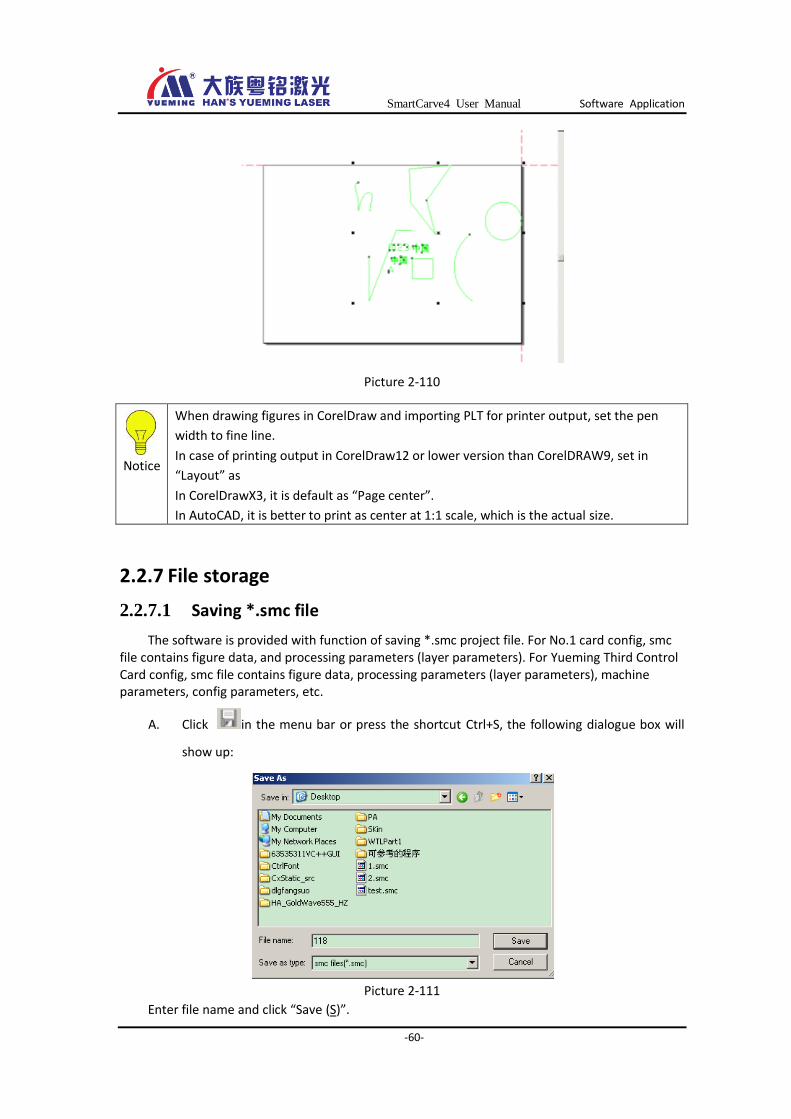
A. Click in the menu bar or press the shortcut Ctrl+S, the following dialogue box will
show up:
Picture 2-111
Enter file name and click “Save (S)”.
Notice
When drawing figures in CorelDraw and importing PLT for printer output, set the pen
width to fine line.
In case of printing output in CorelDraw12 or lower version than CorelDRAW9, set in
“Layout” as
In CorelDrawX3, it is default as “Page center”.
In AutoCAD, it is better to print as center at 1:1 scale, which is the actual size.
SmartCarve4 User Manual Software Application
-61-
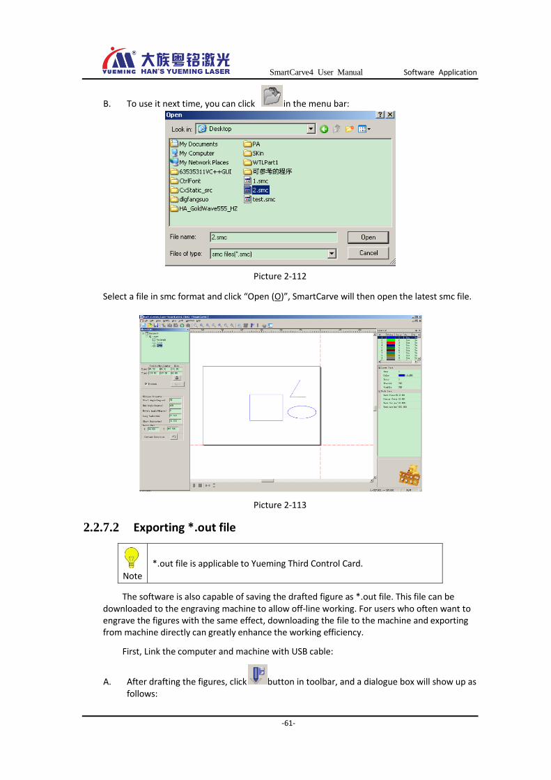
B. To use it next time, you can click in the menu bar:
Picture 2-112
Select a file in smc format and click “Open (O)”, SmartCarve will then open the latest smc file.
Picture 2-113
2.2.7.2 Exporting *.out file
Note
*.out file is applicable to Yueming Third Control Card.
The software is also capable of saving the drafted figure as *.out file. This file can be downloaded to the engraving machine to allow off-line working. For users who often want to engrave the figures with the same effect, downloading the file to the machine and exporting from machine directly can greatly enhance the working efficiency.
First, Link the computer and machine with USB cable:
A. After drafting the figures, click button in toolbar, and a dialogue box will show up as follows:

SmartCarve4 User Manual Software Application
-62-
Picture 2-114
Enter the file name and click “Export file”, a dialogue box will show up:
Picture 2-115
Here you can set all the output parameters of figures, such as how many lines or column is going to be replicated, origin mode, etc. Then, click “OK” to finish.
1. Select “Machine parameters settings” in “Tools” option in menu bar:
Picture 2-116
Then, the machine config dialogue box shows up. Open “Device document” in “Message notification”.

SmartCarve4 User Manual Software Application
-63-
Picture 2-117
Select the port number and click “Link” button. When the “COM” port is opened, you can click “Select a download file” to open the *out file previously saved.
Picture 2-118
Then, click “Download” button to download it to the machine. The download won’t be finished until the progress bar completes.
After that, you can disLink the USB cable, and the machine can then be operated independently.
For more information about the download, please refer to the engraving output in Chapter 3.
2.2.7.3 Exporting *.plt file
The software is also capable of saving the drafted vector diagram as *.plt format.
1. Likewise, after drafting the figures, click button in toolbar, and a dialogue box will show up as follows:
②Device
document
③Select a download
file
④Download
①Port

SmartCarve4 User Manual Software Application
-64-
Picture 2-119
Select “plt files (*.plt)” in “Type (T)”, enter the file name and click “Save (S)”, a dialogue box will pop up:
Picture 2-120
In this dialogue box, user can set path optimization or save as original path. A dialogue box will then pop up as follows:
Picture 2-121
Select the resolution and click “OK” to save it as file of PLT format.

SmartCarve4 User Manual Software Application
-65-
2.2.7.4 Exporting *.ymd file
Note
*.ymd file is only applicable to HAN’S Yueming Third Control Card.
With a config of Yueming Third Control Card, the software is capable of exporting the figures as *.ymd files and downloading it to Yueming Third Control Card control system using the “Network transmission” function.
After drafting the figures, click button in toolbar, and a dialogue box will show up as follows:
Picture 2-123
Select “YueMing Laser Data (*.ymd)”, enter the file name, and click “Save (S)”.
2.3 Track simulation
If you want to simulate the processing of figure on computer, you can click in toolbar, and the path dialogue box will show up:
Picture 2-124
Smoothing: Smooth the cutting track of original figure. After the smoothing processing, the track will be smoother, and it is effective for improving the cutting effect.
Optimization of partition: Separate the figures into several areas basing on the set partition, and follow the sequence of area to perform the cutting.
Path optimization: Re-arrange the sequence of figures, which effectively shortens the cutting path and optimizes the cutting time. Partition owns the highest priority.
Original path: Engrave and export according to the drawing sequence of figures.
Click any one of these buttons, and the track simulation dialogue box will pop up:
SmartCarve4 User Manual Software Application
-66-
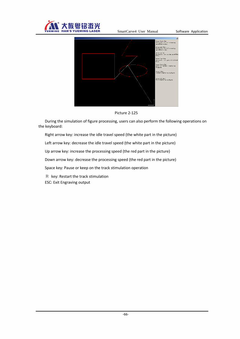
Picture 2-125
During the simulation of figure processing, users can also perform the following operations on the keyboard:
Right arrow key: increase the idle travel speed (the white part in the picture)
Left arrow key: decrease the idle travel speed (the white part in the picture)
Up arrow key: increase the processing speed (the red part in the picture)
Down arrow key: decrease the processing speed (the red part in the picture)
Space key: Pause or keep on the track stimulation operation
R key: Restart the track stimulation
ESC: Exit Engraving output

SmartCarve4 User Manual Carve Out
-67-
Chapter 3 Carve Out
3.1 Yueming first Control Card
3.1.1 Output
When all figure data are ready, it is time to export them to machine for operation. Click in
the toolbar, or right click the mouse in drawing area:
Picture 3-1
A dialogue box will show up as follows:
Picture 3-2
Smooth mode: Smooth the cutting track of original figure. After the smoothing processing, the track will be smoother, and it is effective for improving the cutting effect.
Optimization subarea(mm): Separate the figures into several areas basing on the set partition, and follow the sequence of area to perform the cutting.
As the following pictures show, the original figure is 200mm×100mm in size, if the optimization of partition is set as 50mm, meaning each partition is 50mm×50mm in size, and the
figure is separated into 8 blocks. The cutting sequence would be 1-2-3-4-5-6-7-8.
SmartCarve4 User Manual Carve Out
-68-
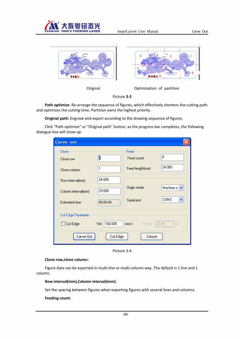
Original Optimization of partition
Picture 3-3
Path optimize: Re-arrange the sequence of figures, which effectively shortens the cutting path and optimizes the cutting time. Partition owns the highest priority.
Original path: Engrave and export according to the drawing sequence of figures.
Click “Path optimize” or “Original path” button, as the progress bar completes, the following dialogue box will show up:
Picture 3-4
Clone row,clone column:
Figure data can be exported in multi-line or multi-column way. The default is 1 line and 1 column.
Row interval(mm),Column interval(mm):
Set the spacing between figures when exporting figures with several lines and columns.
Feeding count:
SmartCarve4 User Manual Carve Out
-69-
It is applicable to automatic feeding equipment. The default value is 0, and the machine cuts for one time. Cutting times of machine=Feeding times+1.
Feed length (mm):
It is the length of feeding at one time, user can set a value as required.
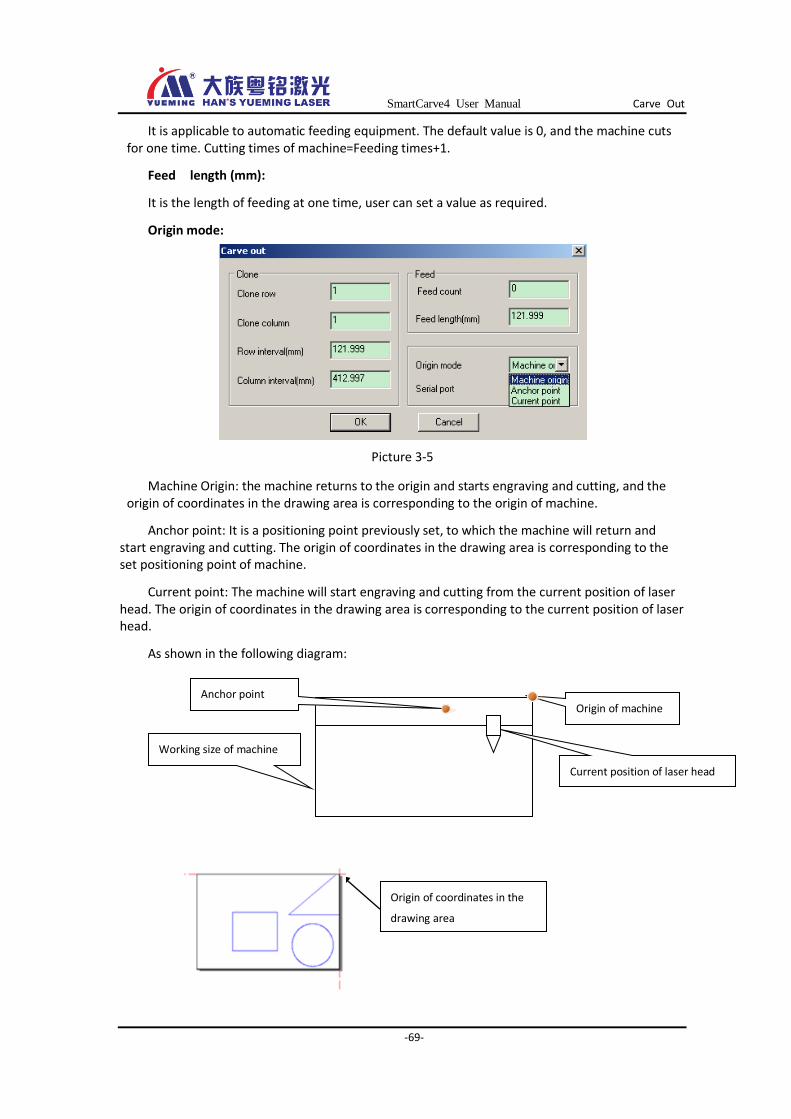
Origin mode:
Picture 3-5
Machine Origin: the machine returns to the origin and starts engraving and cutting, and the origin of coordinates in the drawing area is corresponding to the origin of machine.
Anchor point: It is a positioning point previously set, to which the machine will return and start engraving and cutting. The origin of coordinates in the drawing area is corresponding to the set positioning point of machine.
Current point: The machine will start engraving and cutting from the current position of laser head. The origin of coordinates in the drawing area is corresponding to the current position of laser head.
As shown in the following diagram:
Origin of coordinates in the
drawing area
Working size of machine
Current position of laser head
Origin of machine Anchor point

SmartCarve4 User Manual Carve Out
-70-
Picture 3-6 SmartCarve4 Software
The final output effects of above options are as follows:
Picture 3-7
Serial port:
To ensure the normal output, the port number for Linking computer and machine should be correct (You can view the port in device manager of the system)
YUEMING laser engraving machine is Linked to the computer via the USB port. Before using, driver should be installed properly.
Method of installing driver:
Start the computer and switch on the engraving machine, and then Link the machine to computer using USB cable, at this time a message “Find new hardware…” will be shown on the computer screen as follows:
Picture 3-8
Insert the provided CD into the CD-ROM, a dialogue box will show up as follows after a while:
Origin output Anchor point output
Current point output
SmartCarve4 User Manual Carve Out
-71-
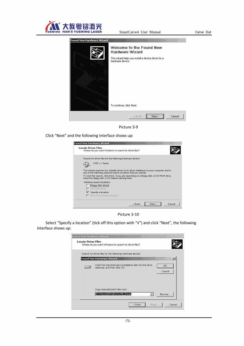
Picture 3-9
Click “Next” and the following interface shows up:
Picture 3-10
Select “Specify a location” (tick off this option with “√”) and click “Next”, the following interface shows up:
SmartCarve4 User Manual Carve Out
-72-
Picture 3-11
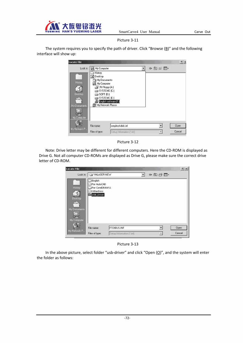
The system requires you to specify the path of driver. Click “Browse (B)” and the following interface will show up:
Picture 3-12
Note: Drive letter may be different for different computers. Here the CD-ROM is displayed as Drive G. Not all computer CD-ROMs are displayed as Drive G, please make sure the correct drive letter of CD-ROM.
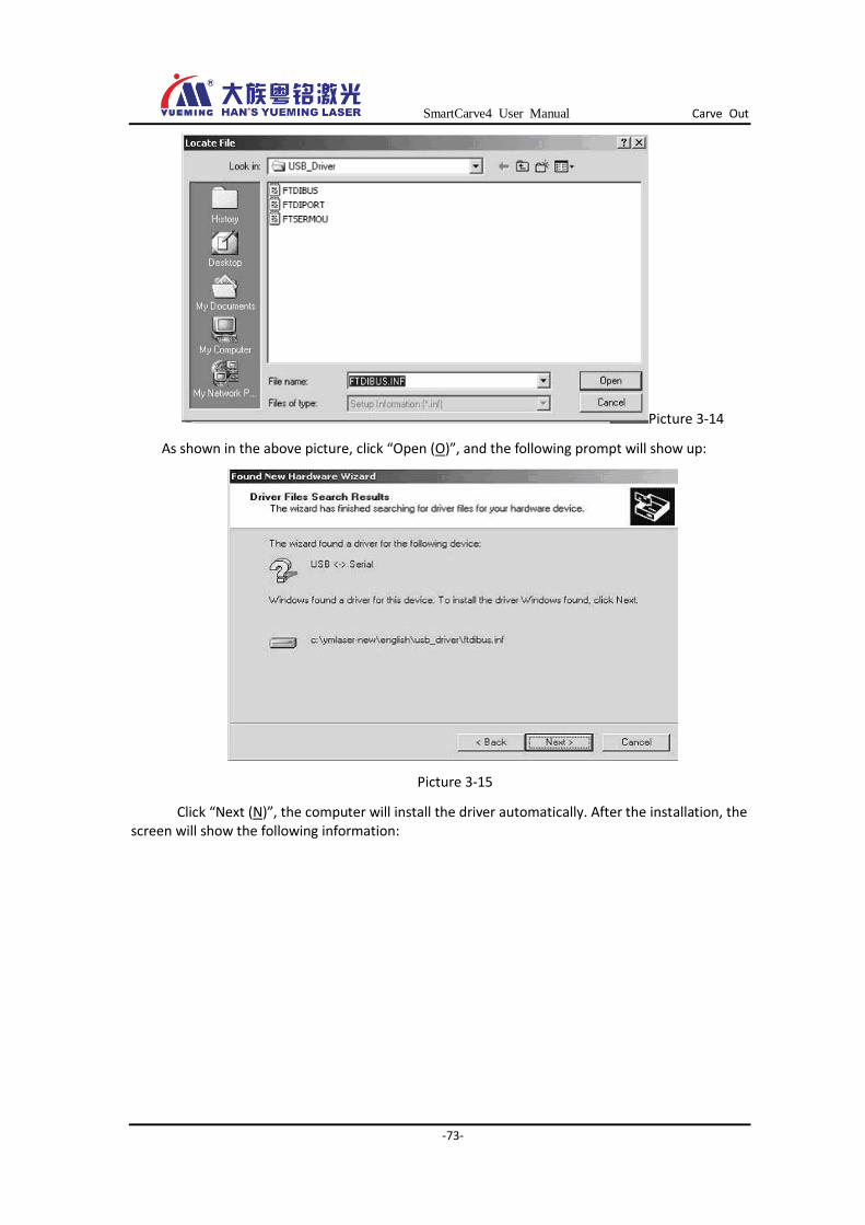
Picture 3-13
In the above picture, select folder “usb-driver” and click “Open (O)”, and the system will enter the folder as follows:
SmartCarve4 User Manual Carve Out
-73-
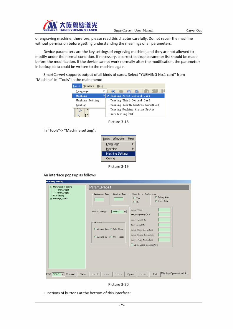
Picture 3-14
As shown in the above picture, click “Open (O)”, and the following prompt will show up:
Picture 3-15
Click “Next (N)”, the computer will install the driver automatically. After the installation, the screen will show the following information:

SmartCarve4 User Manual Carve Out
-74-
Picture 3-16 Click “Finish” button to complete the installation of driver, and then restart the computer.
Note
View the USB port: Go to “Desktop” of Windows, select “My computer”
and right click the mouse to select “Property”, choose the “Hardware” option
and click “Device manager”. In the pop-up window, click “Port (COM and LPT)”
to open it. If it shows “USB SERIAL PORT (COM3)”, it means that the Linked
port is the COM3.
Cut edge parameter:
Cut Edge:whether to cut edge.
Vel:set the vel for cutting edge.
Power:set the power for cutting edge.
Carver Out:
Start to export to the machine. When you click the OK button, there will be a progress indication in the status bar of the software.
Picture 3-17
Cut Edge:
Start task for cutting edge.
Cancel: Exit
3.1.2 Parameter config
This chapter is going to introduce the parameter config and ways to set the parameters of YUEMING machine. Generally, the parameter value of machine will determine the operating state
SmartCarve4 User Manual Carve Out
-75-
of engraving machine; therefore, please read this chapter carefully. Do not repair the machine without permission before getting understanding the meanings of all parameters.
Device parameters are the key settings of engraving machine, and they are not allowed to modify under the normal condition. If necessary, a correct backup parameter list should be made before the modification. If the device cannot work normally after the modification, the parameters in backup data could be written to the machine again.
SmartCarve4 supports output of all kinds of cards. Select “YUEMING No.1 card” from “Machine” in “Tools” in the main menu:
Picture 3-18
In “Tools”-> “Machine setting”:
Picture 3-19
An interface pops up as follows
Picture 3-20
Functions of buttons at the bottom of this interface:

SmartCarve4 User Manual Carve Out
-76-
Port:
It is the communication port between computer and device. The communication between computer and device is done via the port, which means that the image data on the computer and the device parameters are transferred to the device via this port. Our laser No.1 card control system is Linked to the computer via the USB interface.
Link:
Open the selected port. If the computer cannot detect the communication port, it would be unable to communicate with the engraving machine, and a message “Open Com failure” will be displayed in the information bar at the right bottom of interface, at this time you cannot set the device parameters. If the computer can open the port (in other words, recognize the machine), a message “Open Com success” will be displayed and the parameters can be read from the device or you can write parameters into the device.
Clear:
Apart from the selected option in drop-down list, other parameter values will be set as void.
Read:
Read the parameter values saved in device, and display them for user’s reference. If users want to modify the parameters, they should read the device parameters first or open the saved parameter files before modifying (this button is not available when the opening of serial port fails).
Write:
Write the set parameters values into the device and the device will then base on these values to operate. If this button is clicked when the parameters are not completely set, a message “Some Data is Invalidate” will be displayed in the information bar and the parameters would not be written.
The device parameters come into effect as soon as they are written into the machine; however, some special parameters require restarting the machine before coming into effect. (This button is not available when the opening of serial port fails)
Close:
Close the open port, that is, disLink the computer and device. The information bar will show “Close com”.
Open:
Open an available * .ymMachine parameter file
Save:
After reading the factory parameters, user parameters, and notification message, users can save the set parameter files (*.ymMachine format) in file with the user-defined name and under the user-defined catalog.
3.1.2.1 Factory preset
Factory parameter is a reference value or restricted value for the device. User cannot modify the factory settings, but can take these values as a reference.
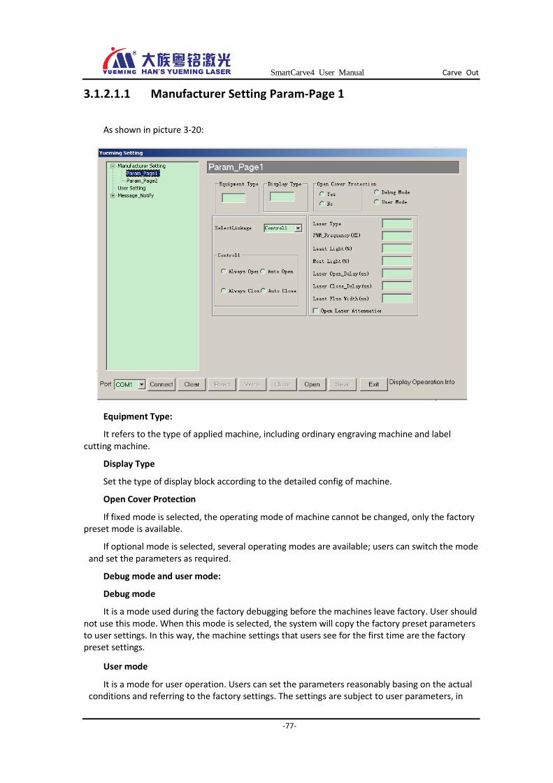
SmartCarve4 User Manual Carve Out
-77-
3.1.2.1.1 Manufacturer Setting Param-Page 1
As shown in picture 3-20:
Equipment Type:
It refers to the type of applied machine, including ordinary engraving machine and label cutting machine.
Display Type
Set the type of display block according to the detailed config of machine.
Open Cover Protection
If fixed mode is selected, the operating mode of machine cannot be changed, only the factory preset mode is available.
If optional mode is selected, several operating modes are available; users can switch the mode and set the parameters as required.
Debug mode and user mode:
Debug mode
It is a mode used during the factory debugging before the machines leave factory. User should not use this mode. When this mode is selected, the system will copy the factory preset parameters to user settings. In this way, the machine settings that users see for the first time are the factory preset settings.
User mode
It is a mode for user operation. Users can set the parameters reasonably basing on the actual conditions and referring to the factory settings. The settings are subject to user parameters, in
SmartCarve4 User Manual Carve Out
-78-
other words, user settings take precedence of factory settings and the machine uses the parameters set by users during the operation. However, the user parameters cannot exceed the factory preset values; otherwise, factory settings would be used instead.
Laser type:
Select the proper laser type according to the kind of laser used by the machine.
PWM frequency:
It is the light intensity frequency of laser tube, and it is different regarding the type of laser tube. For details, please refer to the user manual of laser tube.
Minimum duty ratio:
The minimum duty ratio supported by the machine
Maximum duty ratio:
The maximum duty ratio supported by the machine
Laser on/off delay:
It is a delay parameter set for preventing the uneven edge of start pen and the last pen during the on/off of the laser.
Laser on delay:
The laser may demand some time to start. In order to ensure the synchronization of laser bean and the laser head, the laser should be started in advance before the laser head. We call this measure laser on delay.
Laser off delay:
For the laser may need some time to close the laser bean after having received the closing instruction, to avoid additional engraving, laser should be closed in advance.
Minimal pulse width:
The minimal pulse width that the laser can recognize
Start attenuation compensation:
Laser tube has attenuation rate. It is recommended to choose this option.
Safety protection
Select the option according to the detailed config of device. If the device is provided with cover opening protection (in factory settings, cover opening protection is set as “Yes”), select the “Yes” check box; otherwise, select “No”.
If the safety protection is effective, when users disobey the safety operation regulations (such as opening the end shield, getting close to the engraving machine when it is operating, etc.), the engraving machine will take safety protection measures, such as suspend the operation.
Users can also disable the “safety protection” function as required (set it as “None”) on the condition that the device is under safety protection, for example during the device detection and testing, but this should be done by professionals. It is not recommended for user to do this.
Coordinated control
This option is determined by the config of device.
There are 8 options (1~ 8), capable of controlling 8 external devices. Four control modes are available for each option: always on, always off, auto on, and auto off.
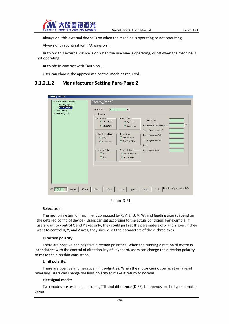
SmartCarve4 User Manual Carve Out
-79-
Always on: this external device is on when the machine is operating or not operating.
Always off: in contrast with “Always on”;
Auto on: this external device is on when the machine is operating, or off when the machine is not operating.
Auto off: in contrast with “Auto on”;
User can choose the appropriate control mode as required.
3.1.2.1.2 Manufacturer Setting Para-Page 2
Picture 3-21
Select axis:
The motion system of machine is composed by X, Y, Z, U, V, W, and feeding axes (depend on the detailed config of device). Users can set according to the actual condition. For example, if users want to control X and Y axes only, they could just set the parameters of X and Y axes. If they want to control X, Y, and Z axes, they should set the parameters of these three axes.
Direction polarity:
There are positive and negative direction polarities. When the running direction of motor is inconsistent with the control of direction key of keyboard, users can change the direction polarity to make the direction consistent.
Limit polarity:
There are positive and negative limit polarities. When the motor cannot be reset or is reset reversely, users can change the limit polarity to make it return to normal.
Elec signal mode:
Two modes are available, including TTL and difference (DIFF). It depends on the type of motor driver.
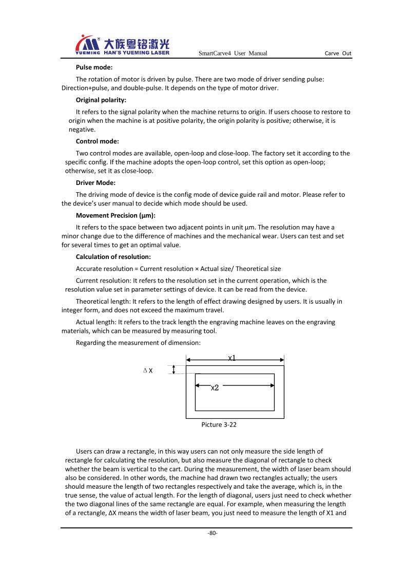
SmartCarve4 User Manual Carve Out
-80-
Pulse mode:
The rotation of motor is driven by pulse. There are two mode of driver sending pulse: Direction+pulse, and double-pulse. It depends on the type of motor driver.
Original polarity:
It refers to the signal polarity when the machine returns to origin. If users choose to restore to origin when the machine is at positive polarity, the origin polarity is positive; otherwise, it is negative.
Control mode:
Two control modes are available, open-loop and close-loop. The factory set it according to the specific config. If the machine adopts the open-loop control, set this option as open-loop; otherwise, set it as close-loop.
Driver Mode:
The driving mode of device is the config mode of device guide rail and motor. Please refer to the device’s user manual to decide which mode should be used.
Movement Precision (µm):
It refers to the space between two adjacent points in unit µm. The resolution may have a minor change due to the difference of machines and the mechanical wear. Users can test and set for several times to get an optimal value.
Calculation of resolution:
Accurate resolution = Current resolution × Actual size/ Theoretical size
Current resolution: It refers to the resolution set in the current operation, which is the resolution value set in parameter settings of device. It can be read from the device.
Theoretical length: It refers to the length of effect drawing designed by users. It is usually in integer form, and does not exceed the maximum travel.
Actual length: It refers to the track length the engraving machine leaves on the engraving materials, which can be measured by measuring tool.
Regarding the measurement of dimension:
Picture 3-22
Users can draw a rectangle, in this way users can not only measure the side length of rectangle for calculating the resolution, but also measure the diagonal of rectangle to check whether the beam is vertical to the cart. During the measurement, the width of laser beam should also be considered. In other words, the machine had drawn two rectangles actually; the users should measure the length of two rectangles respectively and take the average, which is, in the true sense, the value of actual length. For the length of diagonal, users just need to check whether the two diagonal lines of the same rectangle are equal. For example, when measuring the length of a rectangle, ΔX means the width of laser beam, you just need to measure the length of X1 and
ΔX
X2
X1
SmartCarve4 User Manual Carve Out
-81-
X2 and take the average of these two values. The longer the line is, the more accurate the measure would be.
When calculating the accurate resolution of X axis, the actual length is the track the cart moves.
When calculating the accurate resolution of Y axis, the actual length is the track the beam moves.
Test Precision (µm):
This parameter is valid if the device is provided with close-loop detection system. In addition, this parameter determines the error between the engraving size and the designing size. In this situation, users just need to adjust the value of this parameter; the minor change of motion resolution does not influence the engraving size.
If the device is not provided with close-loop detection system, this parameter does not work. The minor change of motion resolution influences the engraving size directly.
Most Speed (mm/s):
Refer to the maximum speed of single-axis motion; it determines the maximum engraving speed and cutting speed
Stop speed (mm/s):
Refer to the emergency stop speed of single-axis motion, also called start-up speed
If the stop speed is great, the impact the device receives during the start-up would be great, and the engraving effect would be bad, but the engraving efficiency would be high;
If the stop speed is slow, the impact the device receives during the start-up would be small, and the engraving effect would be good, but the engraving efficiency would be low;
Most Acc(mm/S2):
Acceleration in single-axis motion, which is expressed in the change rate of speed, meaning a capacity of changing a speed from a value to another in a unit time
If the acceleration is great, the machine would spend a short time to shift a speed to another, improving the engraving efficiency; however, it gives great impact on device and the wearing of machine is great
On the contrary, if the acceleration is small, the engraving efficiency would be low, impact on device would be small, and the wearing of machine would be small
The factory preset acceleration is a guarantee for the device. The greater the acceleration is, the more impact would be put on the device. In this way, it is easy to bring adverse effects on device performance or even cause failure.
To ensure the best operating state of device (the working speed of device is perfectly fit for the engraving effects), the limiting speed and the limit of acceleration should be matched. Generally speaking, users can set a reasonable acceleration according to the requirements for engraving speed and precision.
While meeting the requirements on precision, users can appropriately increase the engraving speed and the acceleration to improve the engraving efficiency.
If the current speed meets the requirements, or the speed during the engraving cannot reach the current set maximum speed, users can decrease the speed appropriately to get products of higher precision with the same efficiency.
Different users may have different engraving environments and requirements, and therefore the limiting speed and the maximum acceleration may be different. Users can practice time and again to get a value that is fit for their engraving requirements.

SmartCarve4 User Manual Carve Out
-82-
Most Space(mm)
Because each beam or guide rail would have a fixed length, so each machine will have a maximum working range, which restricts the machine not to go beyond this range and let the cart and beam move within this range. With the limit of maximum travel, the cart and beam would not run against the wall.
3.1.2.2 User Settings
To get the best processing effects, users can adjust or set the parameters according to the cutting materials, cutting mode, processing characteristics, precision requirements, and efficiency requirements. These parameters are called user parameters. Users can set the parameters for several times before operation. By comparing the samples of engraving products, users can take the parameters, which produce the best engraving effect (meet the users’ requirements), as the settings. Users can save several groups of parameter settings to satisfy the different engraving requirements.
Picture 3-23
Swerve Speed (m/min) It refers to the speed at the corner (such as a right angle). The cornering speed would
influence the engraving effects. If the speed is high, the cornering would be sharp, and the impact or vibration on device
would be great, resulting in the bad engraving effects; however, the efficiency is high If the speed is low, the cornering would be smooth, and the device is run steadily with a high
precision and good engraving effect, but with low efficiency. Users can set the appropriate value according to their requirements on precision. Cut Acceleration (mm/S2) It refers to the acceleration during the cutting (scoring) operation. This acceleration would
influence the cutting effects and operating efficiency. If the acceleration during the cutting is great, the cutting speed would be changed quickly, resulting in the high cutting efficiency but bad cutting effects. However, if the acceleration is small, the cutting speed would be changed slowly and the cutting efficiency would be low but the effect would be good.
Return Point
SmartCarve4 User Manual Carve Out
-83-
It is a home position, at which the device finally stops when the operation complete or after the reset operation.
There are several radio buttons: mechanical origin and positioning point If mechanical origin is selected, the laser head would stop at the mechanical origin after the
operation or the reset. If positioning point is selected, the laser head would stop at the latest user-defined positioning
point after the operation or the reset.
If the mechanical origin and positioning point are at the same point, these two options are equivalent. Users can select any option as required.
Select axis: The motion system of machine is composed by X, Y, Z, U, V, W, and feeding axes (depend on
the detailed config of device). Users can set according to the actual condition. For example, if users want to control X and Y axes only, they could just set the parameters of X and Y axes. If they want to control X, Y, and Z axes, they should set the parameters of these three axes.
Movement Precision (µm): It refers to the space between two adjacent points in unit µm. The resolution may have a
minor change due to the difference of machines and the mechanical wear. Users can test and set for several times to get an optimal value.
Calculation of resolution: Accurate resolution = Current resolution × Actual size/ Theoretical size Current resolution: It refers to the resolution set in the current operation, which is the
resolution value set in parameter settings of device. It can be read from the device. Theoretical length: It refers to the length of effect drawing designed by users. It is usually in
integer form, and does not exceed the maximum travel. Actual length: It refers to the track length the engraving machine leaves on the engraving
materials, which can be measured by measuring tool. Regarding the measurement of dimension:
Users can draw a rectangle, in this way users can not only measure the side length of rectangle for calculating the resolution, but also measure the diagonal of rectangle to check whether the beam is vertical to the cart. During the measurement, the width of laser beam should also be considered. In other words, the machine had drawn two rectangles actually; the users should measure the length of two rectangles respectively and take the average, which is, in the true sense, the value of actual length. For the length of diagonal, users just need to check whether the two diagonal lines of the same rectangle are equal. For example, when measuring the length of a rectangle, ΔX means the width of laser beam, you just need to measure the length of X1 and X2 and take the average of these two values. The longer the line is, the more accurate the measure would be.
When calculating the accurate resolution of X axis, the actual length is the track the cart moves.
When calculating the accurate resolution of Y axis, the actual length is the track the beam moves.
Test Precision (µm):
This parameter is valid if the device is provided with close-loop detection system. In addition, this parameter determines the error between the engraving size and the designing size. In this situation, users just need to adjust the value of this parameter; the minor change of motion resolution does not influence the engraving size.
If the device is not provided with close-loop detection system, this parameter does not work. The minor change of motion resolution influences the engraving size directly.
X
1
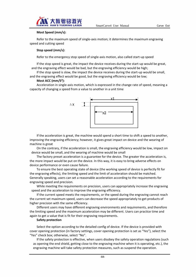
SmartCarve4 User Manual Carve Out
-84-
Most Speed (mm/s):
Refer to the maximum speed of single-axis motion; it determines the maximum engraving speed and cutting speed
Stop speed (mm/s):
Refer to the emergency stop speed of single-axis motion, also called start-up speed
If the stop speed is great, the impact the device receives during the start-up would be great, and the engraving effect would be bad, but the engraving efficiency would be high;
If the stop speed is slow, the impact the device receives during the start-up would be small, and the engraving effect would be good, but the engraving efficiency would be low;
Most ACC (mm/S2): Acceleration in single-axis motion, which is expressed in the change rate of speed, meaning a
capacity of changing a speed from a value to another in a unit time
If the acceleration is great, the machine would spend a short time to shift a speed to another,
improving the engraving efficiency; however, it gives great impact on device and the wearing of machine is great
On the contrary, if the acceleration is small, the engraving efficiency would be low, impact on device would be small, and the wearing of machine would be small
The factory preset acceleration is a guarantee for the device. The greater the acceleration is, the more impact would be put on the device. In this way, it is easy to bring adverse effects on device performance or even cause failure.
To ensure the best operating state of device (the working speed of device is perfectly fit for the engraving effects), the limiting speed and the limit of acceleration should be matched. Generally speaking, users can set a reasonable acceleration according to the requirements for engraving speed and precision.
While meeting the requirements on precision, users can appropriately increase the engraving speed and the acceleration to improve the engraving efficiency.
If the current speed meets the requirements, or the speed during the engraving cannot reach the current set maximum speed, users can decrease the speed appropriately to get products of higher precision with the same efficiency.
Different users may have different engraving environments and requirements, and therefore the limiting speed and the maximum acceleration may be different. Users can practice time and again to get a value that is fit for their engraving requirements.
Safety protection
Select the option according to the detailed config of device. If the device is provided with cover opening protection (in factory settings, cover opening protection is set as “Yes”), select the “Yes” check box; otherwise, select “No”.
If the safety protection is effective, when users disobey the safety operation regulations (such as opening the end shield, getting close to the engraving machine when it is operating, etc.), the engraving machine will take safety protection measures, such as suspend the operation.
ΔX
X2
X1
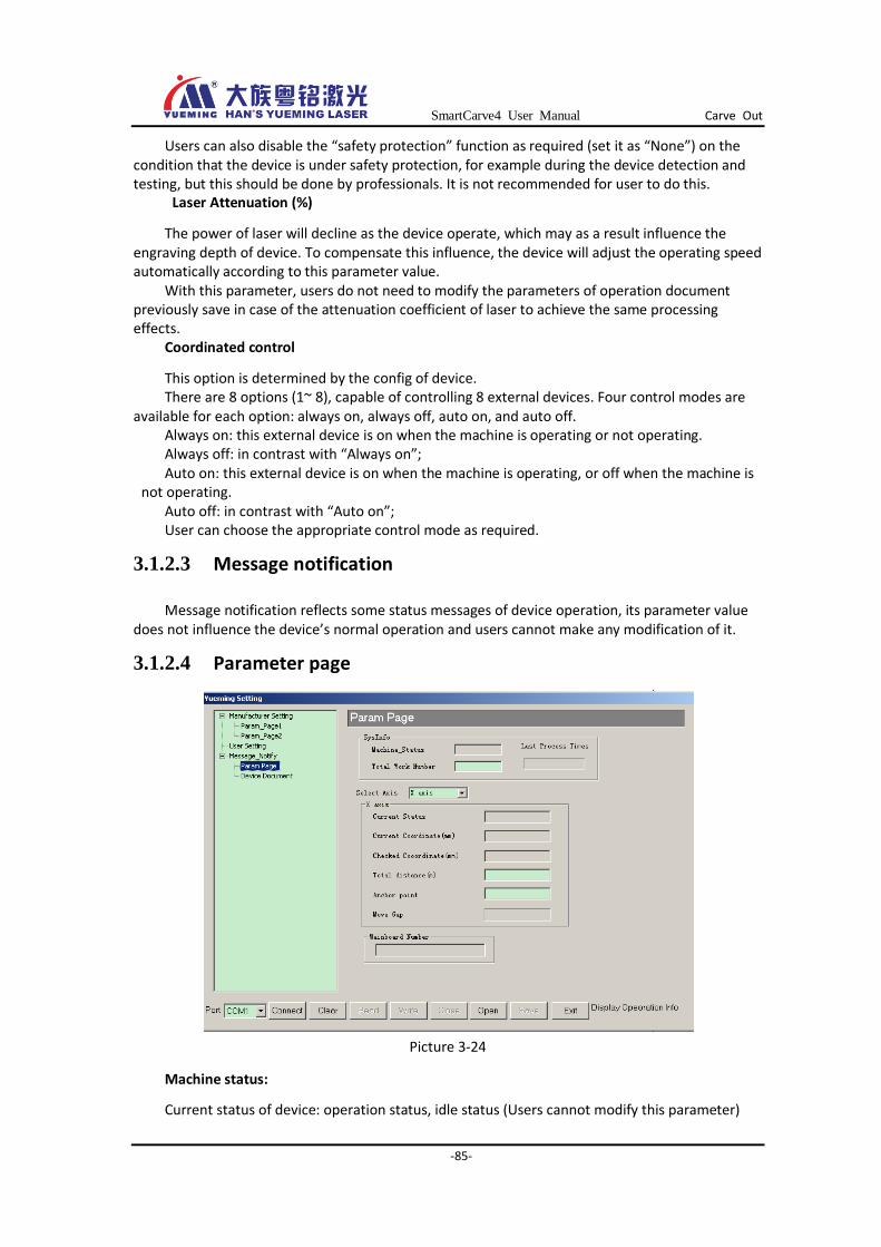
SmartCarve4 User Manual Carve Out
-85-
Users can also disable the “safety protection” function as required (set it as “None”) on the condition that the device is under safety protection, for example during the device detection and testing, but this should be done by professionals. It is not recommended for user to do this.
Laser Attenuation (%)
The power of laser will decline as the device operate, which may as a result influence the engraving depth of device. To compensate this influence, the device will adjust the operating speed automatically according to this parameter value.
With this parameter, users do not need to modify the parameters of operation document previously save in case of the attenuation coefficient of laser to achieve the same processing effects.
Coordinated control
This option is determined by the config of device. There are 8 options (1~ 8), capable of controlling 8 external devices. Four control modes are
available for each option: always on, always off, auto on, and auto off. Always on: this external device is on when the machine is operating or not operating. Always off: in contrast with “Always on”; Auto on: this external device is on when the machine is operating, or off when the machine is
not operating. Auto off: in contrast with “Auto on”; User can choose the appropriate control mode as required.
3.1.2.3 Message notification
Message notification reflects some status messages of device operation, its parameter value does not influence the device’s normal operation and users cannot make any modification of it.
3.1.2.4 Parameter page
Picture 3-24
Machine status:
Current status of device: operation status, idle status (Users cannot modify this parameter)
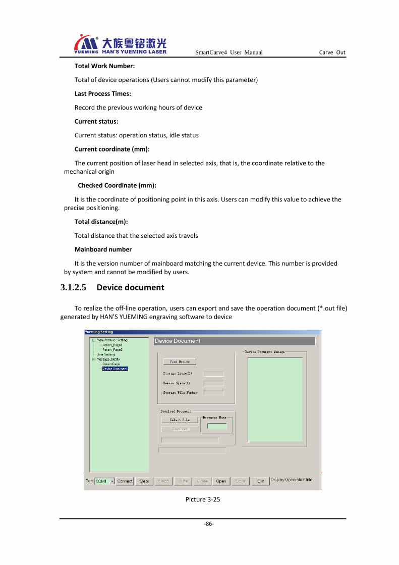
SmartCarve4 User Manual Carve Out
-86-
Total Work Number:
Total of device operations (Users cannot modify this parameter)
Last Process Times:
Record the previous working hours of device
Current status:
Current status: operation status, idle status
Current coordinate (mm):
The current position of laser head in selected axis, that is, the coordinate relative to the mechanical origin
Checked Coordinate (mm):
It is the coordinate of positioning point in this axis. Users can modify this value to achieve the precise positioning.
Total distance(m):
Total distance that the selected axis travels
Mainboard number
It is the version number of mainboard matching the current device. This number is provided by system and cannot be modified by users.
3.1.2.5 Device document
To realize the off-line operation, users can export and save the operation document (*.out file) generated by HAN’S YUEMING engraving software to device
Picture 3-25
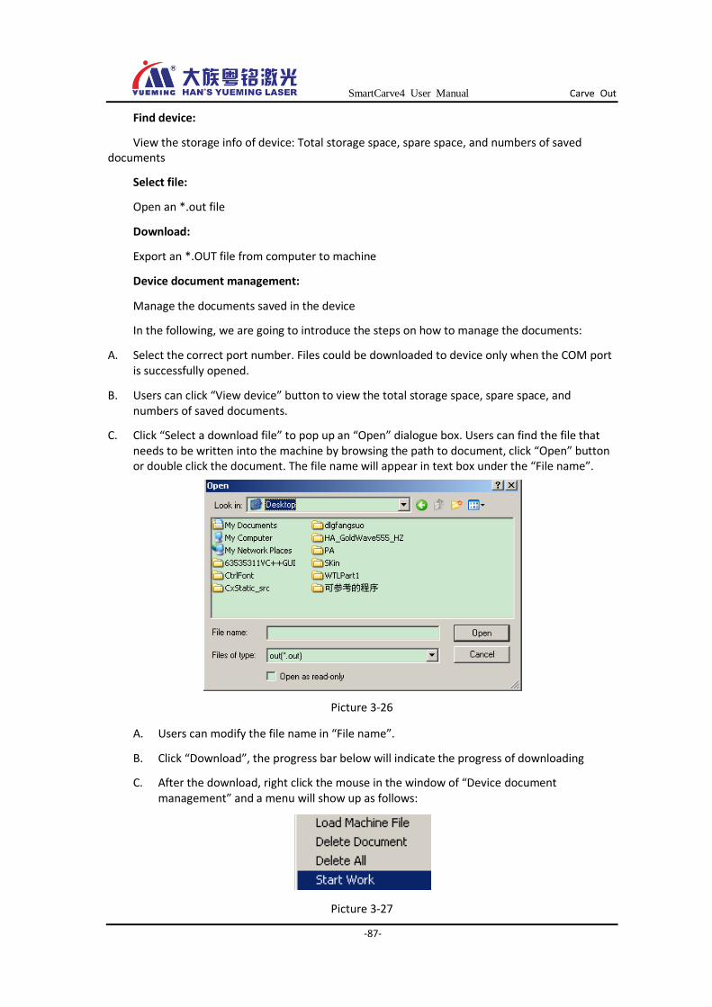
SmartCarve4 User Manual Carve Out
-87-
Find device:
View the storage info of device: Total storage space, spare space, and numbers of saved documents
Select file:
Open an *.out file
Download:
Export an *.OUT file from computer to machine
Device document management:
Manage the documents saved in the device
In the following, we are going to introduce the steps on how to manage the documents:
A. Select the correct port number. Files could be downloaded to device only when the COM port is successfully opened.
B. Users can click “View device” button to view the total storage space, spare space, and numbers of saved documents.
C. Click “Select a download file” to pop up an “Open” dialogue box. Users can find the file that needs to be written into the machine by browsing the path to document, click “Open” button or double click the document. The file name will appear in text box under the “File name”.
Picture 3-26
A. Users can modify the file name in “File name”.
B. Click “Download”, the progress bar below will indicate the progress of downloading
C. After the download, right click the mouse in the window of “Device document management” and a menu will show up as follows:
Picture 3-27
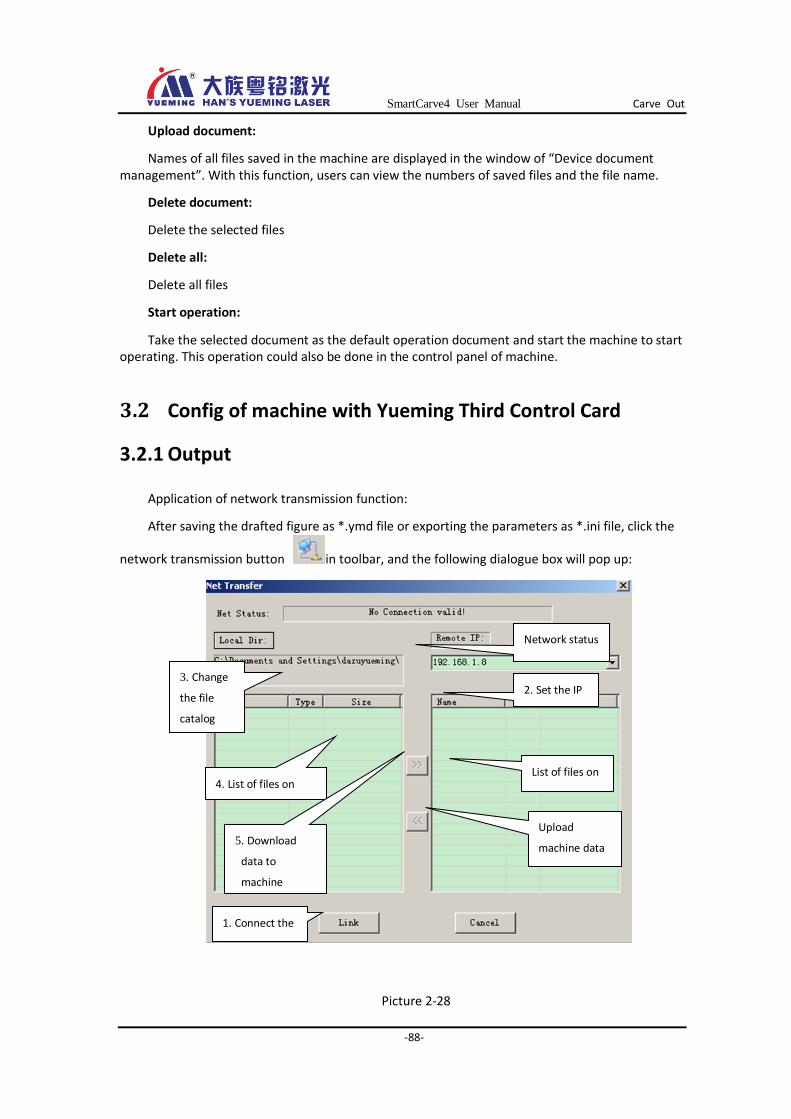
SmartCarve4 User Manual Carve Out
-88-
Upload document:
Names of all files saved in the machine are displayed in the window of “Device document management”. With this function, users can view the numbers of saved files and the file name.
Delete document:
Delete the selected files
Delete all:
Delete all files
Start operation:
Take the selected document as the default operation document and start the machine to start operating. This operation could also be done in the control panel of machine.
3.2 Config of machine with Yueming Third Control Card
3.2.1 Output
Application of network transmission function:
After saving the drafted figure as *.ymd file or exporting the parameters as *.ini file, click the
network transmission button in toolbar, and the following dialogue box will pop up:
Picture 2-28
Network status
message
4. List of files on
computer
List of files on
machine
5. Download
data to
machine
Upload
machine data
to computer
1. Connect the
network
2. Set the IP
address
3. Change
the file
catalog

SmartCarve4 User Manual Carve Out
-89-
Steps to download files to machine:
Link the network. If the network is successfully Linked, network Linked information will be
shown in the network status area.
Set the IP address. It is default as “192.168.1.8”. The IP of machine should also be set as this value.
Change the file catalog in “Local Dir”. In the left file list, there show the figure data files and parameter files.
Select the file(s) and click the right double-headed arrow to download them to machine.
Steps to upload files to computer: After Linking to the network, the current files on machine will be shown at the right file list.
Select a file and click the left double-headed arrow to upload it to the current catalog on the computer.
3.2.2 Parameter config
This chapter is going to introduce the parameter config and ways to set the parameters of the Yueming Third Control Card machine. Generally, the parameter value of machine will determine the operating state of engraving machine; therefore, please read this chapter carefully. Do not repair the machine before getting understanding the meanings of all parameters.
Device parameters are the key settings of engraving machine, and they are not allowed to modify under the normal condition. If necessary, a correct backup parameter list should be made before the modification. If the device cannot work normally after the modification, the parameters in backup data could be written to the machine again.
SmartCarve4 supports output of all kinds of cards. Select “Yueming Third Control Card” from “Machine” in “Tool s” in the main menu:
Picture 3-29
In the main menu, select “Tools”-> “Machine Setting”:
Picture 3-30
The following interface will pop up:
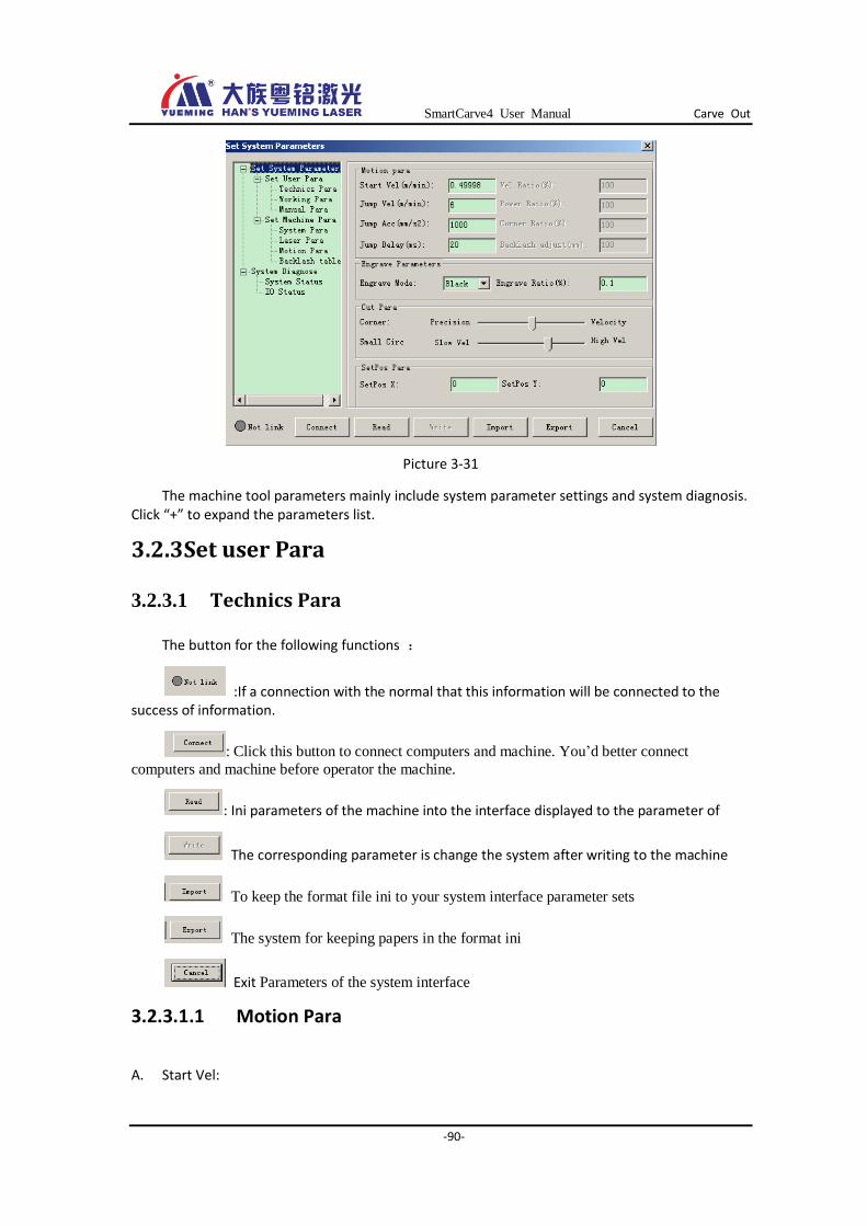
SmartCarve4 User Manual Carve Out
-90-
Picture 3-31
The machine tool parameters mainly include system parameter settings and system diagnosis. Click “+” to expand the parameters list.
3.2.3 Set user Para
3.2.3.1 Technics Para
The button for the following functions :
:If a connection with the normal that this information will be connected to the success of information.
: Click this button to connect computers and machine. You’d better connect
computers and machine before operator the machine.
: Ini parameters of the machine into the interface displayed to the parameter of
The corresponding parameter is change the system after writing to the machine
To keep the format file ini to your system interface parameter sets
The system for keeping papers in the format ini
Exit Parameters of the system interface
3.2.3.1.1 Motion Para
A. Start Vel:
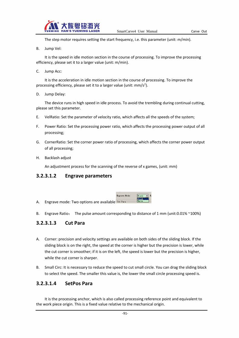
SmartCarve4 User Manual Carve Out
-91-
The step motor requires setting the start frequency, i.e. this parameter (unit: m/min).
B. Jump Vel:
It is the speed in idle motion section in the course of processing. To improve the processing efficiency, please set it to a larger value (unit: m/min).
C. Jump Acc:
It is the acceleration in idle motion section in the course of processing. To improve the processing efficiency, please set it to a larger value (unit: mm/s2).
D. Jump Delay:
The device runs in high speed in idle process. To avoid the trembling during continual cutting, please set this parameter.
E. VelRatio: Set the parameter of velocity ratio, which affects all the speeds of the system;
F. Power Ratio: Set the processing power ratio, which affects the processing power output of all
processing;
G. CornerRatio: Set the corner power ratio of processing, which affects the corner power output
of all processing;
H. Backlash adjust
An adjustment process for the scanning of the reverse of x games, (unit: mm)
3.2.3.1.2 Engrave parameters
A. Engrave mode: Two options are available
B. Engrave Ratio: The pulse amount corresponding to distance of 1 mm (unit:0.01% ~100%)
3.2.3.1.3 Cut Para
A. Corner: precision and velocity settings are available on both sides of the sliding block. If the
sliding block is on the right, the speed at the corner is higher but the precision is lower, while
the cut corner is smoother; if it is on the left, the speed is lower but the precision is higher,
while the cut corner is sharper.
B. Small Circ: It is necessary to reduce the speed to cut small circle. You can drag the sliding block
to select the speed. The smaller this value is, the lower the small circle processing speed is.
3.2.3.1.4 SetPos Para
It is the processing anchor, which is also called processing reference point and equivalent to the work piece origin. This is a fixed value relative to the mechanical origin.
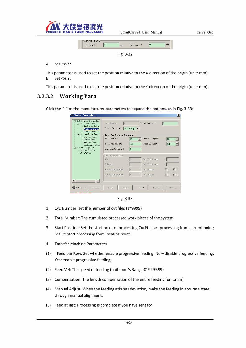
SmartCarve4 User Manual Carve Out
-92-
Fig. 3-32
A. SetPos X:
This parameter is used to set the position relative to the X direction of the origin (unit: mm). B. SetPos Y:
This parameter is used to set the position relative to the Y direction of the origin (unit: mm).
3.2.3.2 Working Para
Click the “+” of the manufacturer parameters to expand the options, as in Fig. 3-33:
Fig. 3-33
1. Cyc Number: set the number of cut files (1~9999)
2. Total Number: The cumulated processed work pieces of the system
3. Start Position: Set the start point of processing,CurPt: start processing from current point;
Set Pt: start processing from locating point
4. Transfer Machine Parameters
(1) Feed par Row: Set whether enable progressive feeding: No – disable progressive feeding;
Yes: enable progressive feeding;
(2) Feed Vel: The speed of feeding (unit :mm/s Range:0~9999.99)
(3) Compensation: The length compensation of the entire feeding (unit:mm)
(4) Manual Adjust: When the feeding axis has deviation, make the feeding in accurate state
through manual alignment.
(5) Feed at last: Processing is complete if you have sent for

SmartCarve4 User Manual Carve Out
-93-
5. Array parameters
(1) Rows: he processing number of work pieces every row in array processing(Range:
1-9999)
(2) Columns: the processing number of work pieces every column in array processing
(1-9999);
(3) Row Distance: the row misalignment of work pieces in array processing (unit: mm,
-999.99 – 999.99);
(4) Col Distance: the column spacing of work pieces in array processing (unit: mm, -999.99 –
999.99);
(5) Row Indnt: the Row misalignment of work pieces in array processing (unit: mm, -999.99 –
999.99);
(6) Col Indnt: the column misalignment of work pieces in array processing (unit: mm, -999.99
– 999.99);
(7) Row Mirror: Used for models with intelliPCInt dual laser heads and the even rows process
the graphs in X /Ydirection mirror imaPCI (0: No; 1: Yes);
(8) Col Mirror: Used for models with intelliPCInt dual laser heads and the even cols process
the graphs in X direction mirror imaPCI (0: No; 1: Yes);
3.2.3.3 Manual Para
The setting interface of Manual is shown in Fig. 3-34
Fig. 3-34
1. Jog Vel: The feeding speed (unit: mm/s, 0-9999.99) when the motion axis feeding is
controlled in manual mode;
2. Jog Acc: The feeding acceleration (unit: mm/s2, 0-9999.99) when the motion axis feeding
is controlled in manual mode;
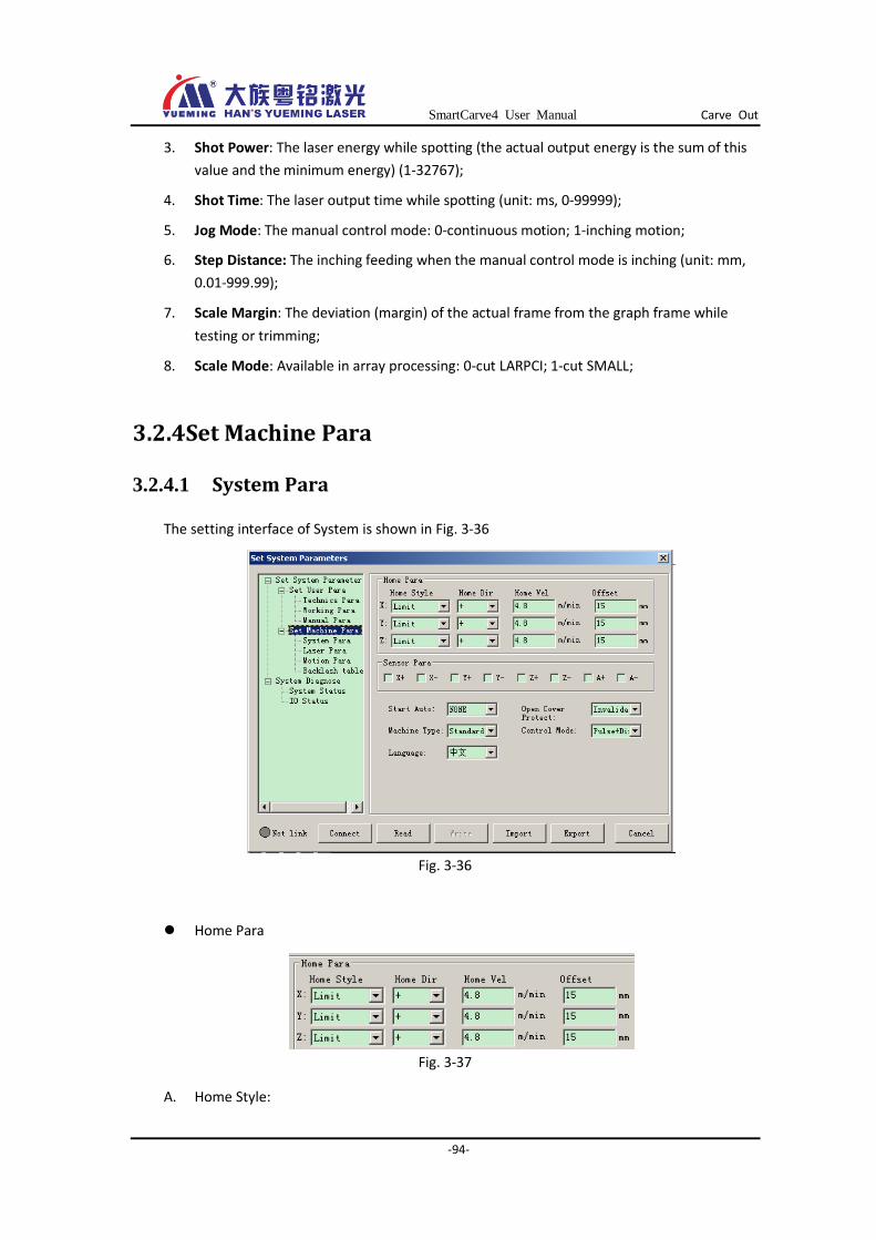
SmartCarve4 User Manual Carve Out
-94-
3. Shot Power: The laser energy while spotting (the actual output energy is the sum of this
value and the minimum energy) (1-32767);
4. Shot Time: The laser output time while spotting (unit: ms, 0-99999);
5. Jog Mode: The manual control mode: 0-continuous motion; 1-inching motion;
6. Step Distance: The inching feeding when the manual control mode is inching (unit: mm,
0.01-999.99);
7. Scale Margin: The deviation (margin) of the actual frame from the graph frame while
testing or trimming;
8. Scale Mode: Available in array processing: 0-cut LARPCI; 1-cut SMALL;
3.2.4 Set Machine Para
3.2.4.1 System Para
The setting interface of System is shown in Fig. 3-36
Fig. 3-36
Home Para
Fig. 3-37
A. Home Style:
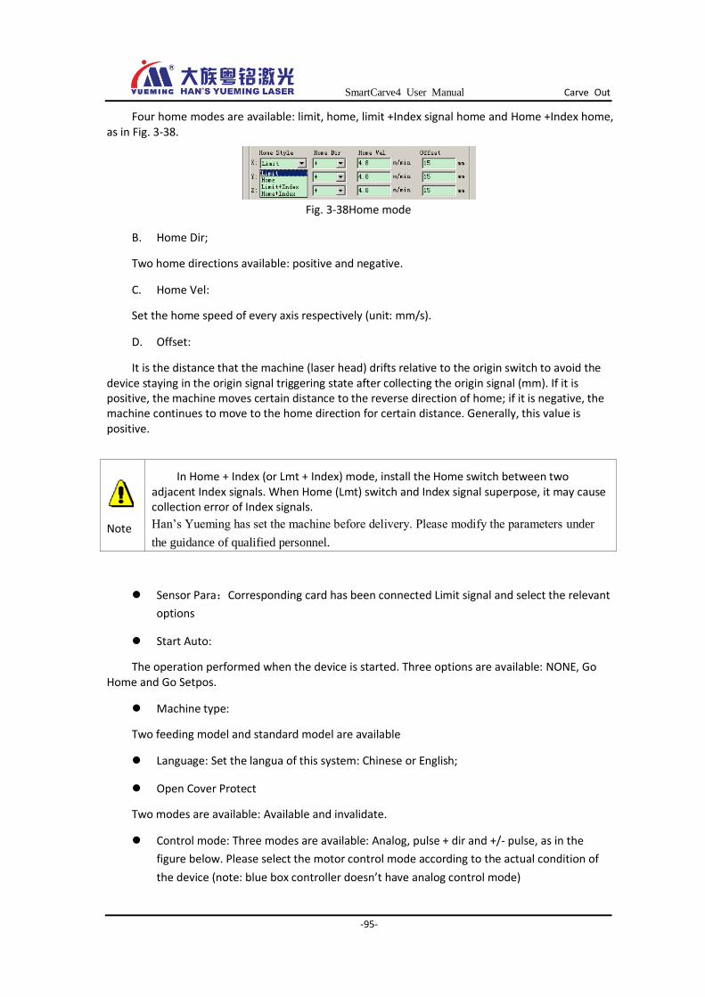
SmartCarve4 User Manual Carve Out
-95-
Four home modes are available: limit, home, limit +Index signal home and Home +Index home, as in Fig. 3-38.
Fig. 3-38Home mode
B. Home Dir;
Two home directions available: positive and negative.
C. Home Vel:
Set the home speed of every axis respectively (unit: mm/s).
D. Offset:
It is the distance that the machine (laser head) drifts relative to the origin switch to avoid the device staying in the origin signal triggering state after collecting the origin signal (mm). If it is positive, the machine moves certain distance to the reverse direction of home; if it is negative, the machine continues to move to the home direction for certain distance. Generally, this value is positive.
Sensor Para:Corresponding card has been connected Limit signal and select the relevant
options
Start Auto:
The operation performed when the device is started. Three options are available: NONE, Go Home and Go Setpos.
Machine type:
Two feeding model and standard model are available
Language: Set the langua of this system: Chinese or English;
Open Cover Protect
Two modes are available: Available and invalidate.
Control mode: Three modes are available: Analog, pulse + dir and +/- pulse, as in the
figure below. Please select the motor control mode according to the actual condition of
the device (note: blue box controller doesn’t have analog control mode)
Note
In Home + Index (or Lmt + Index) mode, install the Home switch between two adjacent Index signals. When Home (Lmt) switch and Index signal superpose, it may cause collection error of Index signals.
Han’s Yueming has set the machine before delivery. Please modify the parameters under
the guidance of qualified personnel.
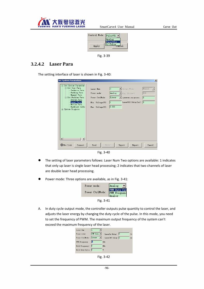
SmartCarve4 User Manual Carve Out
-96-
Fig. 3-39
3.2.4.2 Laser Para
The setting interface of laser is shown in Fig. 3-40:
Fig. 3-40
The setting of laser parameters follows: Laser Num Two options are available: 1 indicates
that only up laser is single laser head processing; 2 indicates that two channels of laser
are double laser head processing.
Power mode: Three options are available, as in Fig. 3-41:
Fig. 3-41
A. In duty cycle output mode, the controller outputs pulse quantity to control the laser, and
adjusts the laser energy by changing the duty cycle of the pulse. In this mode, you need
to set the frequency of PWM. The maximum output frequency of the system can’t
exceed the maximum frequency of the laser.
Fig. 3-42
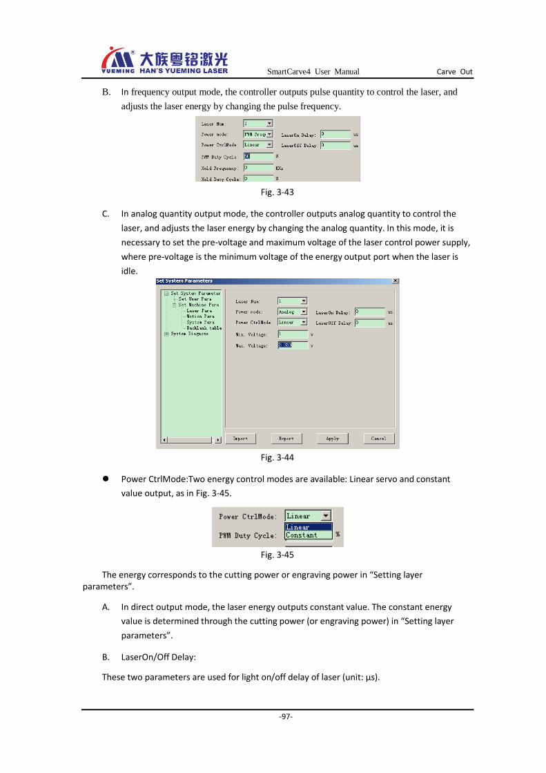
SmartCarve4 User Manual Carve Out
-97-
B. In frequency output mode, the controller outputs pulse quantity to control the laser, and
adjusts the laser energy by changing the pulse frequency.
Fig. 3-43
C. In analog quantity output mode, the controller outputs analog quantity to control the
laser, and adjusts the laser energy by changing the analog quantity. In this mode, it is
necessary to set the pre-voltage and maximum voltage of the laser control power supply,
where pre-voltage is the minimum voltage of the energy output port when the laser is
idle.
Fig. 3-44
Power CtrlMode:Two energy control modes are available: Linear servo and constant
value output, as in Fig. 3-45.
Fig. 3-45
The energy corresponds to the cutting power or engraving power in “Setting layer parameters”.
A. In direct output mode, the laser energy outputs constant value. The constant energy
value is determined through the cutting power (or engraving power) in “Setting layer
parameters”.
B. LaserOn/Off Delay:
These two parameters are used for light on/off delay of laser (unit: μs).

SmartCarve4 User Manual Carve Out
-98-
Because of the hysteresis from the controller sending motion instructions to actual movement of the motor, it is necessary to set this parameter to ensure the synchronization between laser and the motor motion during laser cutting in process.
Fig. 3-46
3.2.4.3 Motion Para
The setting interface of Con X/Y/Z/A is shown in Fig. 3-47:
Fig. 3-47
Set the Con X, Y, Z and A pulse equivalent of the device respectively (unit: pulse/mm).
Whether the pulse equivalent is correct determines whether the actual position of the motion is correct. The user is recommended to keep the pulse equivalents of con X and Y consistent while mechanical designing. This parameter sets the equivalent of every axis respectively to trim the mechanical motion error.
To let the user calculate the pulse equivalent conveniently, this software provides the automatic equivalent calculation function. Click the “Auto Calculate” button to pop up the dialog box below
Fig. 3-48
The procedure follows:

SmartCarve4 User Manual Carve Out
-99-
(1) The user selects the axis to calculate the pulse equivalent first, and enter the set motion
length L (default: 100mm);
(2) Move the selected axis for L distance through “Inching” function in lower computer;
(3) Measure the actual inching distance L of the axis with a rule, and enter this value into the
edit box of actual motion length;
Click the “OK” button and the software calculates the pulse equivalent of current axis.
Soft Limit
Set the mechanical stroke, which is equivalent to soft limit function. (range: 0~9999.99 unit:
mm)
3.2.4.4 Backlash table
Function: Set the reverse clearance during cutting processing, which is shown in Fig. 3-49below:
Fig. 3-49
The reverse clearance depends on the mechanical precision and response speed of the laser. Generally, it is possible to set one group of reverse clearance value (default: 0) because the speed doesn’t change obviously during cutting processing. During engraving processing, since the speed value and the reverse clearance change obviously, it is necessary to set according to the table.
3.2.5 System Diagnose
3.2.5.1 System Status
This function is not applicable to the offline card (It is only applicable to PCI card).
System state function: It is used to view the state of all axes and motion tracks in the system. As the following picture shows:
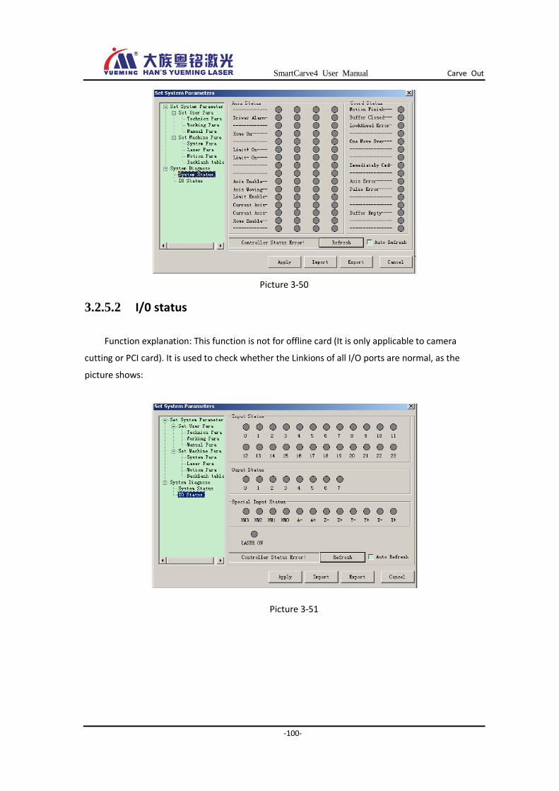
SmartCarve4 User Manual Carve Out
-100-
Picture 3-50
3.2.5.2 I/0 status
Function explanation: This function is not for offline card (It is only applicable to camera
cutting or PCI card). It is used to check whether the Linkions of all I/O ports are normal, as the
picture shows:
Picture 3-51
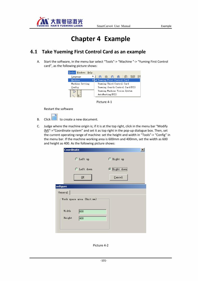
SmartCarve4 User Manual Example
-101-
Chapter 4 Example
4.1 Take Yueming First Control Card as an example
A. Start the software, in the menu bar select “Tools”-> “Machine ”-> “Yuming First Control card”, as the following picture shows:
Picture 4-1
Restart the software
B. Click to create a new document.
C. Judge where the machine origin is; if it is at the top right, click in the menu bar “Modify (M)”->“Coordinate system” and set it as top right in the pop-up dialogue box. Then, set the current operating range of machine: set the height and width in “Tools”-> “Config” in the menu bar. If the machine working area is 600mm and 400mm, set the width as 600 and height as 400. As the following picture shows:
Picture 4-2
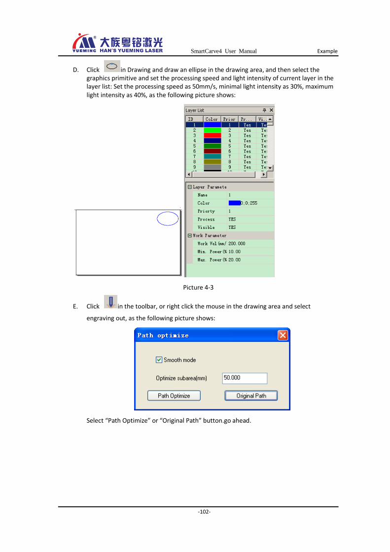
SmartCarve4 User Manual Example
-102-
D. Click in Drawing and draw an ellipse in the drawing area, and then select the graphics primitive and set the processing speed and light intensity of current layer in the layer list: Set the processing speed as 50mm/s, minimal light intensity as 30%, maximum light intensity as 40%, as the following picture shows:
Picture 4-3
E. Click in the toolbar, or right click the mouse in the drawing area and select
engraving out, as the following picture shows:
Select “Path Optimize” or “Original Path” button.go ahead.
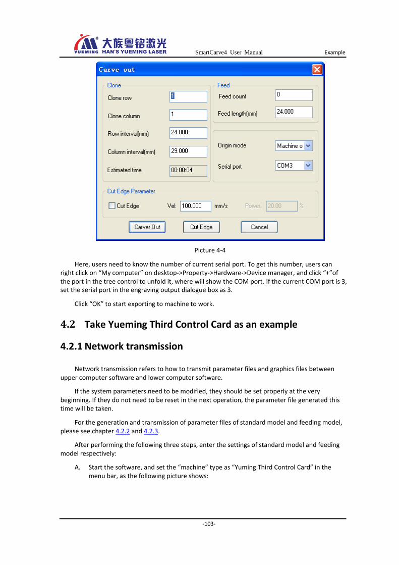
SmartCarve4 User Manual Example
-103-
Picture 4-4
Here, users need to know the number of current serial port. To get this number, users can right click on “My computer” on desktop->Property->Hardware->Device manager, and click “+”of the port in the tree control to unfold it, where will show the COM port. If the current COM port is 3, set the serial port in the engraving output dialogue box as 3.
Click “OK” to start exporting to machine to work.
4.2 Take Yueming Third Control Card as an example
4.2.1 Network transmission
Network transmission refers to how to transmit parameter files and graphics files between upper computer software and lower computer software.
If the system parameters need to be modified, they should be set properly at the very beginning. If they do not need to be reset in the next operation, the parameter file generated this time will be taken.
For the generation and transmission of parameter files of standard model and feeding model, please see chapter 4.2.2 and 4.2.3.
After performing the following three steps, enter the settings of standard model and feeding model respectively:
A. Start the software, and set the “machine” type as “Yuming Third Control Card” in the menu bar, as the following picture shows:
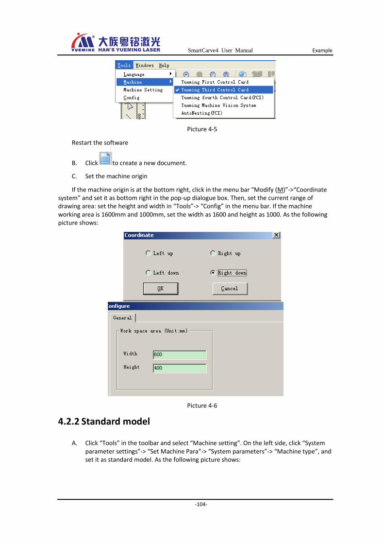
SmartCarve4 User Manual Example
-104-
Picture 4-5
Restart the software
B. Click to create a new document.
C. Set the machine origin
If the machine origin is at the bottom right, click in the menu bar “Modify (M)”->“Coordinate system” and set it as bottom right in the pop-up dialogue box. Then, set the current range of drawing area: set the height and width in “Tools”-> “Config” in the menu bar. If the machine working area is 1600mm and 1000mm, set the width as 1600 and height as 1000. As the following picture shows:
Picture 4-6
4.2.2 Standard model
A. Click “Tools” in the toolbar and select “Machine setting”. On the left side, click “System parameter settings”-> “Set Machine Para”-> “System parameters”-> “Machine type”, and set it as standard model. As the following picture shows:
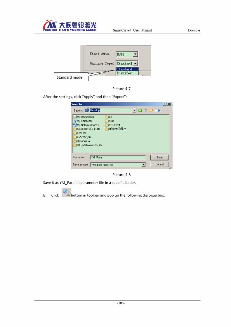
SmartCarve4 User Manual Example
-105-
Picture 4-7
After the settings, click “Apply” and then “Export”:
Picture 4-8
Save it as YM_Para.ini parameter file in a specific folder.
B. Click button in toolbar and pop up the following dialogue box:
Standard model
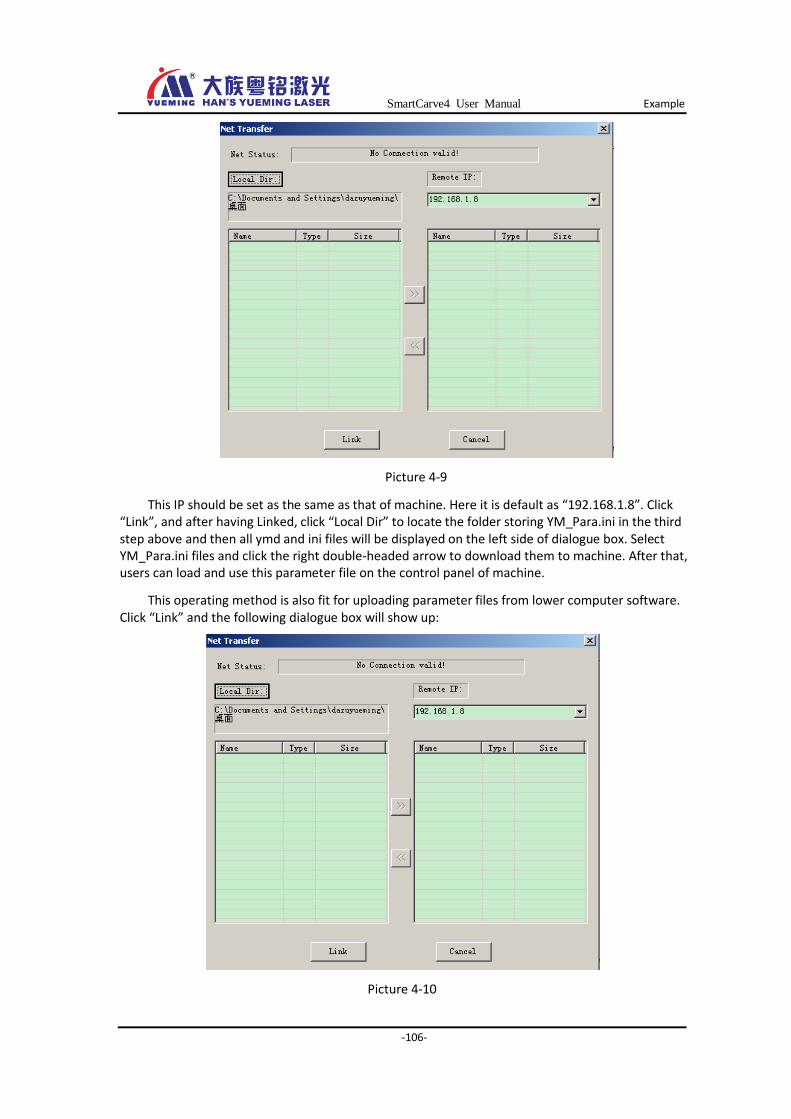
SmartCarve4 User Manual Example
-106-
Picture 4-9
This IP should be set as the same as that of machine. Here it is default as “192.168.1.8”. Click “Link”, and after having Linked, click “Local Dir” to locate the folder storing YM_Para.ini in the third step above and then all ymd and ini files will be displayed on the left side of dialogue box. Select YM_Para.ini files and click the right double-headed arrow to download them to machine. After that, users can load and use this parameter file on the control panel of machine.
This operating method is also fit for uploading parameter files from lower computer software. Click “Link” and the following dialogue box will show up:
Picture 4-10
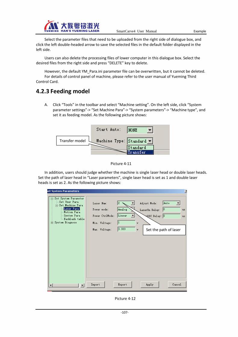
SmartCarve4 User Manual Example
-107-
Select the parameter files that need to be uploaded from the right side of dialogue box, and click the left double-headed arrow to save the selected files in the default folder displayed in the left side.
Users can also delete the processing files of lower computer in this dialogue box. Select the desired files from the right side and press “DELETE” key to delete.
However, the default YM_Para.ini parameter file can be overwritten, but it cannot be deleted. For details of control panel of machine, please refer to the user manual of Yueming Third
Control Card.
4.2.3 Feeding model
A. Click “Tools” in the toolbar and select “Machine setting”. On the left side, click “System parameter settings”-> “Set Machine Para”-> “System parameters”-> “Machine type”, and set it as feeding model. As the following picture shows:
Picture 4-11
In addition, users should judge whether the machine is single laser head or double laser heads. Set the path of laser head in “Laser parameters”, single laser head is set as 1 and double laser heads is set as 2. As the following picture shows:
Picture 4-12
Set the path of laser
head
Transfer model
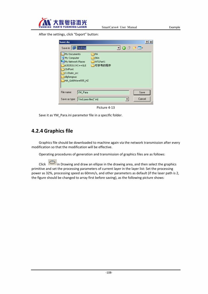
SmartCarve4 User Manual Example
-108-
After the settings, click “Export” button:
Picture 4-13
Save it as YM_Para.ini parameter file in a specific folder.
4.2.4 Graphics file
Graphics file should be downloaded to machine again via the network transmission after every modification so that the modification will be effective.
Operating procedures of generation and transmission of graphics files are as follows:
Click in Drawing and draw an ellipse in the drawing area, and then select the graphics primitive and set the processing parameters of current layer in the layer list: Set the processing power as 32%, processing speed as 60mm/s, and other parameters as default (if the laser path is 2, the figure should be changed to array first before saving), as the following picture shows:
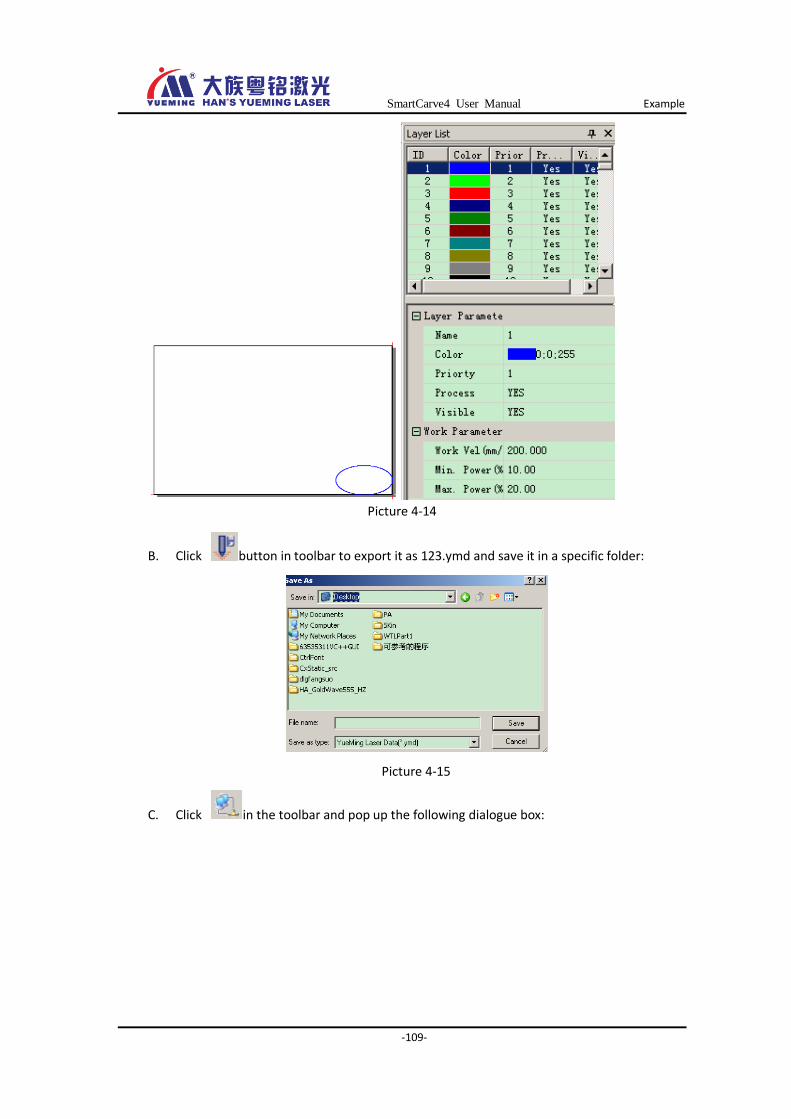
SmartCarve4 User Manual Example
-109-
Picture 4-14
B. Click button in toolbar to export it as 123.ymd and save it in a specific folder:
Picture 4-15
C. Click in the toolbar and pop up the following dialogue box:
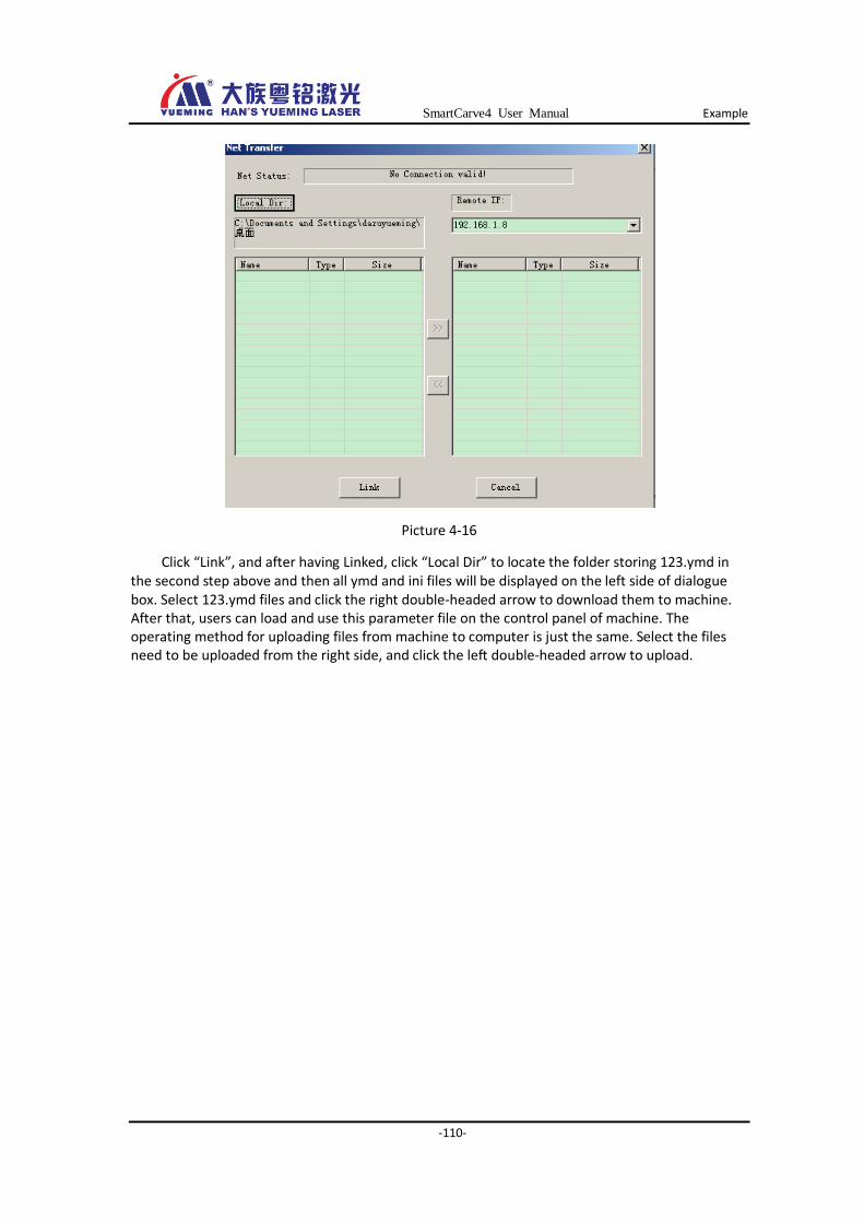
SmartCarve4 User Manual Example
-110-
Picture 4-16
Click “Link”, and after having Linked, click “Local Dir” to locate the folder storing 123.ymd in the second step above and then all ymd and ini files will be displayed on the left side of dialogue box. Select 123.ymd files and click the right double-headed arrow to download them to machine. After that, users can load and use this parameter file on the control panel of machine. The operating method for uploading files from machine to computer is just the same. Select the files need to be uploaded from the right side, and click the left double-headed arrow to upload.
SmartCarve4 User Manual Post
-111-
Post Han’s Yueming Laser Technology Co., Ltd. reserves the right of final interpretation. The
products are subject to changes without prior notice.
All rights reserved! Reprinting or copy without permission is prohibited. We reserve the right of lawing.
广东大族粤铭激光科技股份有限公司
地 址:东莞市松山湖高新技术产业开发区工业东路
28号
电 话:0769-89838888 89839999
传 真:0769-89833333
电子邮件:[email protected]
网 址:http://www.ymlaser.com
GD HAN’S YUEMING LASER Technology Co., Ltd.
Addr :No.28 East Industrial Road,SongShan Lake
Hi-tech Industrial Development zone,Dongguan
City,Guangdong Province P.R.China
TEL.. : 0769-89838888 89839999
FAX. : 0769-89833333
E-mail : [email protected]
Web : http://www.yueminglaser.com/