owner’s manual supplement - harte hanks · windshield wipers in the service position 141 ... 9130...
TRANSCRIPT

OWNER ’S MANUAL SUPPLEMENT


VÄLKOMMEN!
We trust that you will enjoy many years of safe driving in your Volvo, anautomobile designed with your safety and comfort in mind.
This printed supplement is a complement to the owner’s manual availa-ble in the center display. It additionally includes specifications, tire pres-sures and fuses as well as a summary of other important and practicalinformation. To help get the most from your Volvo, we urge you to famili-arize yourself with this supplement and the instructions and mainte-nance information in the owner’s manual. The owner’s manual can alsobe found in a mobile app (Volvo manual) and on Volvo Car’s support siteat support.volvocars.com.
We also urge you and your passengers to wear seat belts at all times inthis (or any other) vehicle. And, of course, please do not operate a vehi-cle if you may be affected by alcohol, medication or any impairment thatcould hinder your ability to drive.
Your Volvo is designed to meet all applicable federal safety and emis-sion standards. If you have any questions regarding your vehicle, pleasecontact your Volvo retailer or see the article "Contacting Volvo" for infor-mation on getting in touch with Volvo in the United States and Canada.

2
INTRODUCTIONContacting Volvo 8
Volvo Roadside Assistance 8
Additional information about your vehicle 8
Volvo and the environment 9
Owner's manual and the environment 10
IntelliSafe—driver support 10
Sensus 11
Owner's manual in mobile devices 14
Options, accessories and the On-board Diagnostic (OBDII) socket
14
Finding owner's information 16
Driver distraction 18
Volvo Structural Parts Statement 19
Crash event data 20
Volvo ID 21
Center display overview 22
Changing center display settings 24
Using the center display keyboard 25
Function view buttons 30
Navigating in the center display's views 32
Symbols in the center display status bar 37
Changing settings in different typesof apps
37
Using the center display 38
Using the owner's manual 42
On-board digital owner's manual 44
Navigating in the digital owner's manual 45
Glass 47
Technician certification 47
IMPORTANT INFORMATIONGeneral safety information 50
Occupant safety 50
Reporting safety defects 51
Recall information 52
Safety during pregnancy 52
Whiplash protection system 53
Seat belts 54
Seat belt pretensioners 55
Buckling and unbuckling seat belts 56
Door and seat belt reminders 58
Airbag system 59
Driver/passenger side airbags 60
Occupant weight sensor 63
Side impact airbags 66
Inflatable curtains 67
Safety mode 68
Starting or moving a vehicle in safetymode
68
Child safety 69
Child restraints 71
Infant seats 73
Convertible seats 75
Booster cushions 77
ISOFIX/LATCH lower anchors 78
Lower child seat attachment points 79
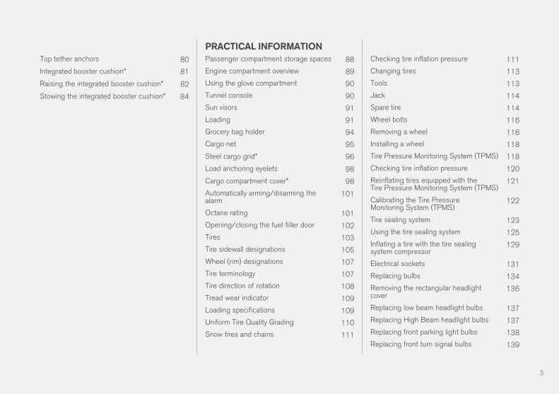
TABLE OF CONTENTS
3
Top tether anchors 80
Integrated booster cushion* 81
Raising the integrated booster cushion* 82
Stowing the integrated booster cushion* 84
PRACTICAL INFORMATIONPassenger compartment storage spaces 88
Engine compartment overview 89
Using the glove compartment 90
Tunnel console 90
Sun visors 91
Loading 91
Grocery bag holder 94
Cargo net 95
Steel cargo grid* 96
Load anchoring eyelets 98
Cargo compartment cover* 98
Automatically arming/disarming thealarm
101
Octane rating 101
Opening/closing the fuel filler door 102
Tires 103
Tire sidewall designations 105
Wheel (rim) designations 107
Tire terminology 107
Tire direction of rotation 108
Tread wear indicator 109
Loading specifications 109
Uniform Tire Quality Grading 110
Snow tires and chains 111
Checking tire inflation pressure 111
Changing tires 113
Tools 113
Jack 114
Spare tire 114
Wheel bolts 116
Removing a wheel 116
Installing a wheel 118
Tire Pressure Monitoring System (TPMS) 118
Checking tire inflation pressure 120
Reinflating tires equipped with theTire Pressure Monitoring System (TPMS)
121
Calibrating the Tire PressureMonitoring System (TPMS)
122
Tire sealing system 123
Using the tire sealing system 125
Inflating a tire with the tire sealingsystem compressor
129
Electrical sockets 131
Replacing bulbs 134
Removing the rectangular headlightcover
136
Replacing low beam headlight bulbs 137
Replacing High Beam headlight bulbs 137
Replacing front parking light bulbs 138
Replacing front turn signal bulbs 139

4
Bulb specifications 139
Replacing wiper blades 140
Windshield wipers in the service position 141
Refilling the windshield washer fluidreservoir
142
Opening and closing the hood 143
Detachable trailer hitch* 144
FUSESFuses 148
Replacing fuses 148
Fuses in the engine compartment 149
Fuses in the passenger compartment 153
Fuses in the cargo compartment 157
SPECIFICATIONSLabel information 162
Dimensions 165
Weights 167
Air conditioning refrigerant 169
Brake fluid specification and volume 169
Coolant specifications 170
Engine specifications 171
Engine oil specifications and volume 173
Fuel tank volume 173
Tire inflation pressure table 174
Transmission fluid specification andvolume
175

5
INDEXIndex 177


INTRODUCTION

INTRODUCTION
8
Contacting VolvoUse the following contact information if youwould like to get in touch with Volvo in the Uni-ted States or Canada.
In the USA:
Volvo Car USA, LLC
Customer Care Center
1 Volvo Drive,
P.O. Box 914
Rockleigh, New Jersey 07647
1-800-458-1552
www.volvocars.com/us
In Canada:
Volvo Car Canada Ltd.
Customer Care Centre
9130 Leslie Street, Suite 101
Richmond Hill, Ontario L4B 0B9
1-800-663-8255
www.volvocars.com/ca
Volvo Roadside AssistanceYour new Volvo comes with a four year VolvoRoadside Assistance program.
Additional information, features, and benefits ofthis program are described in a separate informa-tion package in your glove compartment.
If you require assistance, dial:
In the U.S. 1-800-638-6586 (1-800-63-VOLVO)
In Canada 1-800-263-0475
Additional information about yourvehicleVolvo Cars' website and support site provideadditional information about your vehicle.
Support on the Internet
Go to support.volvocars.com to visit the site,which is available in most markets.
The information on the support site is searchableand is grouped into different categories. Itincludes support for e.g., Internet-based servicesand functions, Volvo On Call, the navigation sys-tem and apps. Video and step-by-step instruc-tions explain various procedures such as how toconnect the vehicle to the Internet via a cellphone.
Downloadable information
MapsSensus Navigation system maps can be down-loaded from the support site.
Mobile appsBeginning with model year 2014, the owner'smanual is available in the form of an app for cer-tain Volvo models. The Volvo On Call app canalso be found here.

INTRODUCTION
9
Owner's manuals for earlier model VolvosOwner's manuals for earlier model Volvos areavailable in PDF format. Quick Guides and sup-plements can also be found on the support site.Select a model and a model year and downloadthe desired information.
ContactContact information for customer support and thenearest Volvo retailer are available on the site.
Related information• Using the owner's manual (p. 42)
• On-board digital owner's manual (p. 44)
• Volvo ID (p. 21)
Volvo and the environmentVolvo is committed to the well-being of its cus-tomers. As a natural part of this commitment, wecare about the environment in which we all live.Concern for the environment means an everydayinvolvement in reducing our environmentalimpact.
Volvo's environmental activities are based on aholistic view, which means we consider the over-all environmental impact of a product throughoutits complete life cycle. In this context, design, pro-duction, product use, and recycling are all impor-tant considerations. In production, Volvo haspartly or completely phased out several chemicalsincluding CFCs, lead chromates, asbestos, andcadmium; and reduced the number of chemicalsused in our plants 50% since 1991.
Volvo was the first in the world to introduce intoproduction a three-way catalytic converter with aLambda sond, now called the heated oxygen sen-sor, in 1976. The current version of this highlyefficient system reduces emissions of harmfulsubstances (CO, HC, NOx) from the exhaust pipeby approximately 95 – 99% and the search toeliminate the remaining emissions continues.Volvo is the only automobile manufacturer tooffer CFC-free retrofit kits for the air conditioningsystem of all models as far back as the 1975model 240. Advanced electronic engine controlsand cleaner fuels are bringing us closer to ourgoal. In addition to continuous environmental
refinement of conventional gasoline-poweredinternal combustion engines, Volvo is activelylooking at advanced technology alternative-fuelvehicles.
When you drive a Volvo, you become our partnerin the work to lessen the car's impact on theenvironment. To reduce your vehicle's environ-mental impact, you can:
• Maintain proper air pressure in your tires.Tests have shown decreased fuel economywith improperly inflated tires.
• Follow the recommended maintenanceschedule in your Warranty and ServiceRecords Information booklet.
• Drive at a constant speed whenever possible.
• See a trained and qualified Volvo servicetechnician as soon as possible for inspectionif the check engine (malfunction indicator)light illuminates, or stays on after the vehiclehas started.
• Properly dispose of any vehicle-related wastesuch as used motor oil, used batteries, brakepads, etc.
• When cleaning your vehicle, please use gen-uine Volvo car care products. All Volvo carcare products are formulated to be environ-mentally friendly.

INTRODUCTION
* Option/accessory.10
Owner's manual and theenvironmentThe wood pulp in Volvo's printed owner's infor-
mation comes from FSC® (Forest Stewardship
Council®) certified forests and other responsiblesources.
FSC®
The symbol above indicates that the wood pulp is
FSC® certified.
Related information• Volvo and the environment (p. 9)
IntelliSafe—driver supportIntelliSafe is Volvo's philosophy regarding vehi-cle safety. It encompasses a number of systems,both standard and optional, that are designed tohelp make driving and traveling in a Volvo safer.
SupportSystems that help make driving safer are an inte-gral part of IntelliSafe. These include optionalfeatures such as Adaptive Cruise Control* thathelps maintain a set distance to a vehicle ahead,Park Assist Pilot*, which assists in parking thevehicle, Cross Traffic Alert*, Blind SpotInformation*, etc.
Accident preventionSystems such as City Safety are designed toautomatically apply the brakes in situations inwhich the driver does not have time to react.Lane Keeping Aid* alerts the driver if the vehicleinadvertently crosses a lane's/road's side markerline.
ProtectionThe vehicle is equipped with e.g., seat belt pre-tensioners that pull the seat belts taut in criticalsituations when there is a collision risk andnumerous airbags designed to help provide cush-ioning if certain types of collisions should occur.
Related information• Airbag system (p. 59)
• Seat belts (p. 54)
• General safety information (p. 50)

INTRODUCTION
}}
11
SensusSensus is the core of your personal Volvo experi-ence and provides information, entertainmentand features that make owning your vehicle eas-ier.
This is Sensus
Sensus provides an intelligent interface andInternet-connected service with an intuitive navi-gation structure that offers access to relevantinformation when it is needed, with minimal dis-tractions.
Sensus also includes all of your vehicle's solu-tions relating to entertainment, connecting to theInternet, navigation and the user interfacebetween the driver and the vehicle. Sensusmakes communication between you, the vehicleand the digital world around you possible.

||
INTRODUCTION
* Option/accessory.12
Information when it's needed, where it's needed
Information is presented in different displays depending on how it should be prioritized (generic illustration)
Head-up-display*
The head up-display presents types of informa-tion that the driver should be aware of immedi-
ately, such as traffic warnings, speed informationand navigation. Road sign information and incom-ing phone calls are also displayed here. Thehead-up display is controlled from the right-sidesteering wheel keypad and the center display.
Instrument panel
12" instrument panel

INTRODUCTION
* Option/accessory. 13
8" instrument panel
The instrument panel displays information suchas speed, an incoming phone call or the trackthat is currently playing. It is controlled using bothsteering wheel keypads.
Center display
Many of the vehicle's main functions are con-trolled from the center display, a touchscreen thatreacts to taps or other gestures. The number ofphysical buttons is thereby minimized. The screencan be operated with or without gloves.
The center display is used to control e.g., the cli-mate and infotainment systems and to adjust thepower seats*. The information shown here can bedealt with by the driver or the front seat passen-ger.
Voice control systemThe voice control system ena-bles the driver to operate cer-tain vehicle functions withoutremoving his/her hands fromthe steering wheel and itunderstands natural speech.Use voice commands to e.g.,
play a track on the infotainment system, make aphone call, raise the passenger compartmenttemperature or to read a text message.
For additional information about all of the func-tions/system, see the respective articles in theon-board owner's manual or the printed supple-ment.
Related information• Using the center display (p. 38)
• Center display overview (p. 22)
• Navigating in the center display's views(p. 32)

INTRODUCTION
14
Owner's manual in mobile devicesOwner's information mobile app1 can be down-loaded from the App Store and Google Play andis adapted for both cell phones and tablets.These apps also contain videos and interior/exterior hotspot views of the vehicle that you canclick on for additional information.
This QR code will take youdirectly to the app or you cansearch for "Volvo manual" inthe App Store or Google Play.
The app contains videos and exterior/interiorviews of the vehicle with certain components/functions highlighted in hotspots, which leaddirectly to related information. It is easy to navi-gate between the various categories and articlesand the contents are searchable.
The mobile app is available at the App Store and GooglePlay
Related information• Using the owner's manual (p. 42)
Options, accessories and the On-board Diagnostic (OBDII) socket We strongly recommend that Volvo ownersinstall only genuine, Volvo-approved accesso-ries, and that accessory installations be per-formed only by a trained and qualified Volvoservice technician.
Optional or accessory equipment described inthis manual is indicated by an asterisk.
Optional or accessory equipment may not beavailable in all countries or markets. Please notethat some vehicles may be equipped differently,depending on special legal requirements.
Contact your Volvo retailer for additional informa-tion.
1 Certain models and mobile devices

INTRODUCTION
}}
15
NOTE
• Do not export your Volvo to anothercountry before investigating that coun-try's applicable safety and exhaust emis-sion requirements. In some cases it maybe difficult or impossible to comply withthese requirements. Modifications to theemission control system(s) may renderyour Volvo not certifiable for legal opera-tion in the U.S., Canada and other coun-tries.
• All information, illustrations and specifica-tions contained in this manual are basedon the latest product information availa-ble at the time of publication. Please notethat some vehicles may be equipped dif-ferently, depending on market-specificadaptations or special legal requirements.Optional equipment described in thismanual may not be available in all mar-kets.
• Some of the illustrations shown aregeneric and are intended as examplesonly, and may not depict the exact modelfor which this owner's information isintended.
• Volvo reserves the right to make modeland product changes at any time, or tochange specifications or design withoutnotice and without incurring obligation.
WARNING
If your vehicle is involved in an accident,unseen damage may affect its drivability andsafety.
WARNING
CALIFORNIA proposition 65
Engine exhaust, some of its constituents, andcertain vehicle components contain or emitchemicals known to the state of California tocause cancer, and birth defects or otherreproductive harm. In addition, certain fluidscontained in vehicles and certain products ofcomponent wear contain or emit chemicalsknown to the State of California to cause can-cer, and birth defects or other reproductiveharm.
WARNING
Certain components of this vehicle such as airbag modules, seat belt pretensioners, adap-tive steering columns, and button cell batter-ies may contain Perchlorate material. Specialhandling may apply for service or vehicle endof life disposal.
See www.dtsc.ca.gov/hazardouswaste/perchlorate.
• Genuine Volvo accessories are tested toensure compatibility with the performance,safety, and emission systems in your vehicle.
Additionally, a trained and qualified Volvoservice technician knows where accessoriesmay and may not be safely installed in yourVolvo. In all cases, please consult a trainedand qualified Volvo service technician beforeinstalling any accessory in or on your vehicle.
• Accessories that have not been approved byVolvo may or may not be specifically testedfor compatibility with your vehicle. Addition-ally, an inexperienced installer may not befamiliar with some of your car's systems.
• Any of your car's performance and safetysystems could be adversely affected if youinstall accessories that Volvo has not tested,or if you allow accessories to be installed bysomeone unfamiliar with your vehicle.
• Damage caused by unapproved or improperlyinstalled accessories may not be covered byyour new vehicle warranty. See your Warrantyand Service Records Information booklet formore warranty information. Volvo assumes noresponsibility for death, injury, or expensesthat may result from the installation of non-genuine accessories.

||
INTRODUCTION
16
Connecting equipment to the On-boardDiagnostic (OBDII) socket
WARNING
Volvo Cars takes no responsibility for the con-sequences of connecting non-authorizedequipment to the On-board Diagnostic(OBDII) socket. This socket should only beused by a trained and qualified Volvo servicetechnician.
The diagnostic socket OBDII under the dashboard onthe driver's side
Type approvalUSA
FCC ID: 2AGKKACUII-06
This device complies with Part 15 of the FCCrules. Operation is subject to the following twoconditions:
(1) This device may not cause harmful interfer-ence, and
(2) this device must accept any interferencereceived, including interference that may causeundesired operation.
WARNING
Changes or modifications not expresslyapproved by the party responsible for compli-ance could void the user's authority to oper-ate the equipment.
Canada
IC: 20839-ACUII06
This device complies with Industry Canadalicence-exempt RSS standard(s). Operation issubject to the following two conditions:
(1) this device may not cause interference, and
(2) This device must accept any interferencereceived, including interference that may causeundesired operation.
Finding owner's informationOwner's information is available in several differ-ent formats in both digital and printed form. Theowner's manual is available on the vehicle's cen-ter display, as a mobile app and on Volvo's sup-port website.
There is also a Quick Guide in the glove com-partment as well as a printed supplement to theowner's manual containing information aboute.g., fuses, specifications, etc. A complete prin-ted owner's manual can also be ordered.

INTRODUCTION
17
The vehicle's center displayIn the center display, pull downTop view and tap Owner'smanual. This gives you accessto visual navigation with exteriorand interior images of the vehi-cle. The information is searcha-ble and is divided into catego-
ries.
Mobile appIn App Store or Google Play,search for "Volvo Manual."Download the app to a smart-phone or tablet and select avehicle model. The app con-tains instructive videos andoffers visual navigation, includ-
ing interior and exterior images of the vehicle.Navigation between the various articles in theowner's manual is designed to provide easyaccess to the information and the information issearchable.
Volvo Cars' support siteGo to support.volvocars.comand select your country.Owner's manuals are availablehere online and in PDF format.Volvo Cars' support site alsocontains instructional videosand additional information
about your vehicle and owning a Volvo.
Printed owner's informationThe glove compartment con-tains a printed supplement tothe owner’s manual containinginformation about fuses andspecifications as well as a sum-mary of other important andpractical information.
A printed Quick Guide can also be found in theglove compartment containing useful informationabout the most commonly used features andfunctions in your vehicle.
Other printed owner's information may also befound in the vehicle, depending on optionsand/or accessories that the vehicle is equippedwith.
A complete printed version of the owner's infor-mation (or a new owner's manual supplement)can be ordered through a Volvo retailer.
NOTE
If the content of the digital information in thecenter display and the printed information dif-fer, the printed information always has prece-dence.
WARNING
The driver is always responsible for operatingthe vehicle in a safe manner and adhering tocurrent laws and traffic regulations.
It is also important that the vehicle be oper-ated, maintained and serviced according toVolvo's recommendations/instructions in theowner's manual.
Changing the language used in thevehicle's center displayChanging languages in the center display couldmean that some of the owner's information provi-ded may not comply with national or local stat-utes and regulations. Changing to a languagethat you do not understand may also make it diffi-cult to change back to the original language.
Related information• Owner's manual in mobile devices (p. 14)
• Navigating in the digital owner's manual(p. 45)
• On-board digital owner's manual (p. 44)
• Navigating in the digital owner's manual(p. 45)
• Using the owner's manual (p. 42)
• Additional information about your vehicle(p. 8)

INTRODUCTION
18
Driver distractionPlease keep the following warnings in mindwhen operating/servicing your vehicle.
A driver has a responsibility to do everything pos-sible to ensure his or her own safety and thesafety of passengers in the vehicle and otherssharing the roadway. Avoiding distractions is partof that responsibility.
Driver distraction results from driver activities thatare not directly related to controlling the vehiclein the driving environment. Your new Volvo is, orcan be, equipped with many feature-rich enter-tainment and communication systems. Theseinclude hands-free cellular telephones, navigationsystems, and multipurpose audio systems. Youmay also own other portable electronic devicesfor your own convenience. When used properlyand safely, they enrich the driving experience.Improperly used, any of these could cause a dis-traction.
For all of these systems, we want to provide thefollowing warning that reflects the strong Volvoconcern for your safety. Never use these devicesor any feature of your vehicle in a way that dis-tracts you from the task of driving safely. Distrac-tion can lead to a serious accident. In addition tothis general warning, we offer the following guid-ance regarding specific newer features that maybe found in your vehicle:
WARNING
• Never use a hand-held cellular telephonewhile driving. Some jurisdictions prohibitcellular telephone use by a driver whilethe vehicle is moving.
• If your vehicle is equipped with a naviga-tion system, set and make changes toyour travel itinerary only with the vehicleparked.
• Never program your audio system whilethe vehicle is moving. Program radio pre-sets with the vehicle parked, and use yourprogrammed presets to make radio usequicker and simpler.
• Never use portable computers or per-sonal digital assistants while the vehicleis moving.
Accessory installation• We strongly recommend that Volvo owners
install only genuine, Volvo-approved acces-sories, and that accessory installations beperformed only by a trained and qualifiedVolvo service technician.
• Genuine Volvo accessories are tested toensure compatibility with the performance,safety, and emission systems in your vehicle.Additionally, a trained and qualified Volvoservice technician knows where accessoriesmay and may not be safely installed in yourVolvo. In all cases, please consult a trained
and qualified Volvo service technician beforeinstalling any accessory in or on your vehicle.
• Accessories that have not been approved byVolvo may or may not be specifically testedfor compatibility with your vehicle. Addition-ally, an inexperienced installer may not befamiliar with some of your car's systems.
• Any of your car's performance and safetysystems could be adversely affected if youinstall accessories that Volvo has not tested,or if you allow accessories to be installed bysomeone unfamiliar with your vehicle.
• Damage caused by unapproved or improperlyinstalled accessories may not be covered byyour new vehicle warranty. See your Warrantyand Service Records Information booklet formore warranty information. Volvo assumes noresponsibility for death, injury, or expensesthat may result from the installation of non-genuine accessories.

INTRODUCTION
19
WARNING
The driver is always responsible for operatingthe vehicle in a safe manner and for comply-ing with current statutes and regulations.
It is also essential to maintain and service thevehicle according to Volvo's recommendationsas stated in the owner's information and theservice and warranty booklet.
If the on-board information differs from theprinted owner's manual, the printed informa-tion always takes precedence.
Related information• Volvo Structural Parts Statement (p. 19)
Volvo Structural Parts StatementVolvo has always been and continues to be aleader in automotive safety.
Volvo engineers and manufactures vehiclesdesigned to help protect vehicle occupants in theevent of a collision.
Volvos are designed to absorb the impact of acollision. This energy absorption system including,but not limited to, structural components such asbumper reinforcement bars, bumper energyabsorbers, frames, rails, fender aprons, A-pillars,B-pillars and body panels must work together tomaintain cabin integrity and protect the vehicleoccupants.
The supplemental restraint system including butnot limited to air bags, side curtain air bags, anddeployment sensors work together with theabove components to provide proper timing forair bag deployment.
Due to the above, Volvo Car USA does not sup-port the use of aftermarket, alternative or any-thing other than original Volvo parts for collisionrepair.
Volvo Car USA also recommends using Volvo-approved replacement glass. The use of after-market glass, particularly a windshield, can havean adverse effect on collision avoidance andadvanced lighting systems.
In addition Volvo does not support the use or re-use of structural components from an existing
vehicle that has been previously damaged.Although these parts may appear equivalent, it isdifficult to tell if the parts have been previouslyreplaced with non-OE parts or if the part hasbeen damaged as a result of a prior collision. Thequality of these used parts may also have beenaffected due to environmental exposure.
Related information• Crash event data (p. 20)
• Contacting Volvo (p. 8)

INTRODUCTION
20
Crash event dataThis vehicle is equipped with an event datarecorder (EDR). The main purpose of an EDR isto record, in certain crash or near crash-like sit-uations, such as an air bag deployment or hittinga road obstacle, data that will assist in under-standing how a vehicle's systems performed.The EDR is designed to record data related tovehicle dynamics and safety systems for a shortperiod of time, typically 30 seconds or less. TheEDR in this vehicle is designed to record suchdata as:
• How various systems in your vehicle wereoperating;
• Whether or not the driver and passengersafety belts were buckled/fastened;
• How far (if at all) the driver was depressingthe accelerator and/or brake pedal; and,
• How fast the vehicle was traveling.
These data can help provide a better understand-ing of the circumstances in which crashes andinjuries occur.
EDR data are recorded by your vehicle only if anon-trivial crash situation occurs; no data arerecorded by the EDR under normal driving condi-tions and the EDR never registers who is drivingthe vehicle or the location of a crash or a nearcrash-like situation. However, other parties, suchas law enforcement, could combine the EDR datawith the type of personally identifying data rou-
tinely acquired during a crash investigation. Toread data recorded by an EDR, special equipmentis required, and access to the vehicle or the EDRis needed.
Furthermore, your vehicle is equipped with anumber of computers whose task is to continu-ously control and monitor the vehicle’s operation.They can also register some of this informationduring normal driving conditions, most importantlyif they detect a fault relating to the vehicle’s oper-ation and functionality or upon activation of thevehicle’s active safety systems (e.g. City Safetyand the auto-brake function). Some of the regis-tered information is required by technicians whencarrying out service and maintenance to enablethem to diagnose and rectify any faults that haveoccurred in the vehicle and to enable Volvo to ful-fill legal and other regulatory requirements. Infor-mation thus registered in the vehicle is registeredin the vehicle’s computers until the vehicle isserviced or repaired. In addition to the above, theregistered information may – on an aggregatedbasis – be used for research and product devel-opment purposes in order to continuouslyimprove the safety and quality of Volvo vehicles.
For additional information, contact:
In the United States
Volvo Car USA, LLC
Customer Care Center
1 Volvo Drive, P.O. box 914
Rockleigh, New Jersey 07647
1-800-458-1552
www.volvocars.com/us
In Canada
Volvo Car Canada Ltd.
Customer Care Centre
9130 Leslie Street
Richmond Hill, Ontario L4B 0B9
1-800-663-8255
www.volvocars.com/ca

INTRODUCTION
21
Volvo IDA Volvo ID can be used to access a number of
online services2
Creating a Volvo IDA Volvo ID can be created in two ways:
Using the Volvo ID app1. If you have not already done so, download
the Volvo ID app from the DownloadCenter.
2. Start the app and register a personal emailaddress.
3. Follow the instructions that will be sent auto-matically to this email address.
> A Volvo ID has now been created and hasbeen automatically registered to the vehi-cle. The Volvo ID services available cannow be used.
Using the Volvo On Call app1. Download the latest version of the Volvo On
Call app to your cell phone from e.g., the AppStore, Windows Phone or Google Play.
2. Start the app and create a Volvo ID on thestart page.
3. Register a personal email address and thenfollow the instructions that will be sent auto-matically to this address.
Registering your Volvo ID to the vehicleIf your Volvo ID was created using the Volvo OnCall mobile app, the ID has to be registered tothe vehicle:
1. With the vehicle connected to the Internet,download the Volvo ID app from theDownload Center in the center display'sApp view. See also the article "Downloading,updating and uninstalling apps."
2. Start the app and enter your Volvo ID.
3. Follow the instructions that will be sent auto-matically to the email address linked to yourVolvo ID.
> Your Volvo ID is now registered to thevehicle and the Volvo ID services availablecan be used.
Advantages of having a Volvo ID• Only one user name and password are
required to access online services.
• If you change a user name or password forone of the online service (e.g., Volvo On Call),it/they will also be automatically changed forthe other services.
2 These services vary and may be subject to change. Consult your Volvo retailer.

INTRODUCTION
22
Center display overviewMany of the vehicle's functions are controlledfrom the center display.
Three of the center display's basic views. Swipe to the right/left to access the Function/App view (generic illustration)

INTRODUCTION
* Option/accessory. 23
Function view: vehicle functions can be acti-vated/deactivated by tapping. Certain func-tions are called "trigger functions", whichopen settings windows, e.g., Camera andparking functions. Settings for the head-updisplay* are also started from Function viewbut the actual interaction is controlled fromthe steering wheel keypad buttons and theinstrument panel.
Home view: the initial view shown when thecenter display is started.
App (Application) view: shows apps that havebeen downloaded (third-party apps) as wellas ones for integrated functions such as FMradio. Tap an icon to open the app.
Status bar: vehicle activities are shown at thetop of the screen. Network/connection infor-mation is shown on the left side of the bar.Media-related information, the clock andinformation about background activities areshown to the right.
Top view: pull down the tab to open Top view.From here, you can access Settings,Owner's manual and stored messages.
Navigation: leads to map navigation. Tap thesub-view to expand it.
Media: the most recently used media-relatedapps. Tap the sub-view to expand it.
Phone: used to access phone-related func-tions. Tap the sub-view to expand it.
The extra sub-view: the most recently usedapps/vehicle functions that do not belong inany of the other sub-views are listed here.Tap the sub-view to expand it.
Climate bar: information and direct access tosettings such as temperature, seat heating*and blower speed. Tap the symbol at thecenter of the Climate bar to open Climateview for additional settings.
Related information• Using the center display (p. 38)

INTRODUCTION
24
Changing center display settingsThe center display activates automatically whenthe driver's door is opened. Settings can bemade for e.g., sounds, background and themes.
Turning off or changing the volume ofcenter display soundsSystem sounds in the center display can beturned off or their volume can be changed:
1. Tap Settings in the center display's Topview.
2. Tap Sound System Volumes.
3. Pull the control under Screen Touch to thedesired level to change volume or turn offthe sound for tapping the screen or KeypadTouch.
Changing the screen's appearance(theme)1. Tap Settings in the center display's Top
view.
2. Tap My Car Displays DisplayThemes.
3. Select a theme, e.g., Minimalistic orChrome Rings.
In addition, the settings: Normal and Bright canalso be selected. For Normal, the screen's back-ground is dark and the text is light. This is thedefault setting. If Bright is selected, the back-
ground will be light and the text will be dark,which can increase readability in strong ambientlighting.
These alternatives are always available and donot shift automatically according to changes inambient lighting.
Related information• Using the center display (p. 38)
• Sensus (p. 11)

INTRODUCTION
}}
25
Using the center display keyboardA keyboard can be used on the center display toenter characters and search for e.g., destina-tions using the navigation system, adding con-tacts in phone book, etc. It is also possible touse handwriting on the screen.
Entering text using the keyboardThe keyboard will only appear at the bottom ofthe center display in situations when it is possibleto write on the screen.
NOTE
The keyboard cannot be used if the vehicle ismoving.

||
INTRODUCTION
26
Keyboard function buttons (the appearance may vary depending on language settings, context, etc.)
Field for possible search hits. The wordchanges as new letters are added. Scroll inthe list using the left/right arrows. Tap a
word to select it. The keyboard may not sup-port all language selections, in which casethis line on the screen will not be displayed.
The characters that can be entered are lan-guage-dependent (see point 7). Tap a char-acter to enter it.

INTRODUCTION
}}
27
Several buttons (depending on the contextfor which the keyboard is being used) will bedisplayed here. In certain cases, it can beused to enter @ (for an email address) or tostart a new line.
Press to hide the keyboard. In cases wherethis is not possible, the button will not be dis-played.
Tap once to enter one uppercase letter.Double-tap for Caps lock (tap again toreturn to lowercase letters). Letters enteredafter the !, . and ? characters will automati-cally be uppercase. The first letter in the textfield or in text fields intended for names,addresses or company names will also auto-matically be uppercase. The first letter in textfields intended for passwords, webaddresses or email addresses will automati-cally be lowercase unless upper case ischosen.
Press to display the numbers that can beentered. When numbers are displayed, tap
to resume entering text or toenter special characters.
Tap to change the keyboard language (in thisexample, English is the selected language).The characters available will change accord-ing to the selected language (2). This buttonwill only be displayed if several keyboard lan-guages have been selected (see the section"Changing keyboard languages" below).Press and hold to display a list of possible
languages and tap a language to use it. Toadd keyboard languages, see the heading"Changing keyboard languages" below.
Tap to enter blank spaces.
Tap to erase one character at a time.
Tap to enable handwriting. See the section"Handwritten text" below.
Tap the button above the keyboard to confirm thetext that has been entered (not shown in theillustration). This button's appearance differsdepending on the context.
Changing keyboard languagesIn order to change keyboard languages, theymust first be selected under Settings.
The keyboard language can be changed withoutchanging the language used for the other sys-tems/menus in the vehicle.
1. Pull down the center display's Top view andtap Settings.
2. Tap System Keyboard Layouts.
3. Select and one or more of the languages inthe list.
> This makes it possible to change the key-board layout and characters availabledepending on the language(s) selected.
When more than one languagehas been selected, this button(7) will appear on the keyboard.
To shift between keyboard languages by display-ing the list of available languages:
1. Press and hold the button (7).
> A list will be displayed.
2. Tap the desired language. If more than fourlanguages have been selected in Settings,scroll in the list.
> The keyboard layout and characters avail-able will change to the selected language.
To shift between keyboard languages withoutdisplaying the list of available languages:
– Tap the button (7).
> The keyboard will switch to the next lan-guage in the list (without displaying thelist itself).
||
INTRODUCTION
28
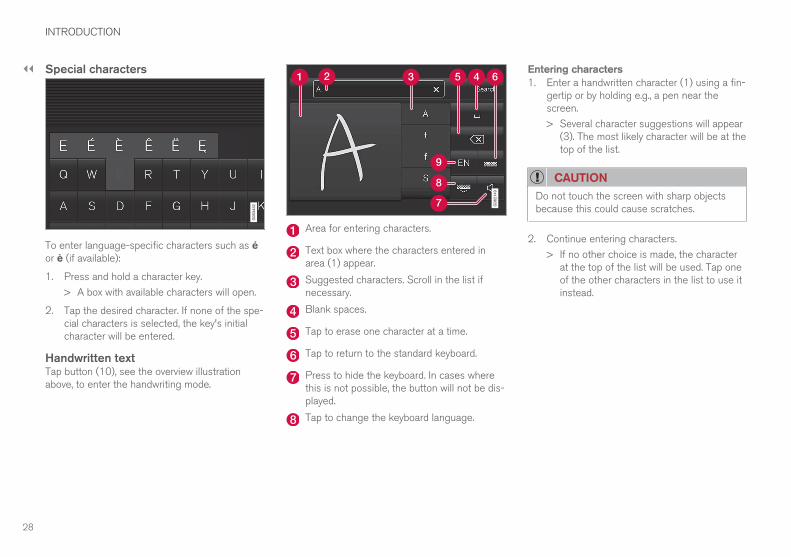
Special characters
To enter language-specific characters such as éor è (if available):
1. Press and hold a character key.
> A box with available characters will open.
2. Tap the desired character. If none of the spe-cial characters is selected, the key's initialcharacter will be entered.
Handwritten textTap button (10), see the overview illustrationabove, to enter the handwriting mode.
Area for entering characters.
Text box where the characters entered inarea (1) appear.
Suggested characters. Scroll in the list ifnecessary.
Blank spaces.
Tap to erase one character at a time.
Tap to return to the standard keyboard.
Press to hide the keyboard. In cases wherethis is not possible, the button will not be dis-played.
Tap to change the keyboard language.
Entering characters1. Enter a handwritten character (1) using a fin-
gertip or by holding e.g., a pen near thescreen.
> Several character suggestions will appear(3). The most likely character will be at thetop of the list.
CAUTION
Do not touch the screen with sharp objectsbecause this could cause scratches.
2. Continue entering characters.
> If no other choice is made, the characterat the top of the list will be used. Tap oneof the other characters in the list to use itinstead.
INTRODUCTION
29
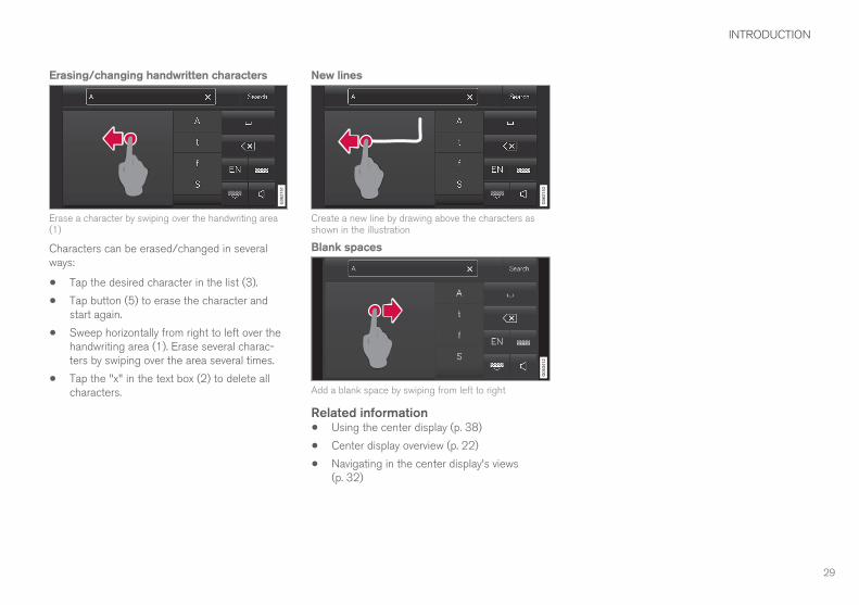
Erasing/changing handwritten characters
Erase a character by swiping over the handwriting area(1)
Characters can be erased/changed in severalways:
• Tap the desired character in the list (3).
• Tap button (5) to erase the character andstart again.
• Sweep horizontally from right to left over thehandwriting area (1). Erase several charac-ters by swiping over the area several times.
• Tap the "x" in the text box (2) to delete allcharacters.
New lines
Create a new line by drawing above the characters asshown in the illustration
Blank spaces
Add a blank space by swiping from left to right
Related information• Using the center display (p. 38)
• Center display overview (p. 22)
• Navigating in the center display's views(p. 32)

INTRODUCTION
30
Function view buttonsThe Function view, which is one of the centerdisplay's basic views, contains all of the vehicle's
on-screen function buttons. From the Homeview, swipe from left to right on the screen tocome to the Function view.
Different types of buttonsThere are three different types of vehicle functionbuttons as listed in the following table.
Type of button Functions Vehicle function affected
Function buttons Have On/Off modes.
An LED indicator light to the left of the button's icon will illuminate when a function isactive. Press the button to turn the function on or off.
Most of the buttons in the function view arefunction buttons.
Start buttons Do not have On/Off modes.
Pressing a start button opens a function's window, e.g., a window for adjusting thedriver's seat.
• Camera.
• Headrest fold.
• Functions for folding down a seat.
• Head-up display adjustments.
Parking buttons Have On/Off and scanning modes.
Similar to function buttons but have an additional parking scanning mode.
• Park In.
• Park Out.
Button modes
A function is activated (on) when the LED indicator isgreen
A function is deactivated (off) when the LED indicator isoff
When a function or parking button's LED indica-tor is green, the function is activated. When afunction is initially activated, an additional text willbe displayed (certain functions only) in the buttonfor approx. 5 seconds, after which the button willbe displayed with the LED indicator illuminated.
Press the button briefly to deactivate the func-tion.

INTRODUCTION
31
The yellow triangle indicates that the function is notworking correctly
Related information• Center display overview (p. 22)
• Navigating in the center display's views(p. 32)

INTRODUCTION
32
Navigating in the center display'sviewsThere are 5 different basic views in the centerdisplay: Home view, Top view, Climate view, Appview and Function view. The display is activatedautomatically when the driver's door is opened.
Home viewHome view is displayed when the screen is acti-vated. It consists of four sub-views: Navigation,Media, Phone and an extra sub-view. The extrasub-view contains the most recently used app/vehicle function that is not related to the otherthree sub-views. For example, if the most recently
used app/vehicle function is a music app, theMedia sub-view will be displayed.
The sub-views display brief information about therespective apps.
The first time the vehicle is started, some of theHome view's sub-views will not contain any infor-mation.
NOTE
In Home view's standard mode (reached bypressing the Home button briefly), an anima-tion explaining how to access the differentviews will be shown on the screen.
NOTE
When the vehicle is moving:
• Some functions (using the center displaykeyboard, etc.) may be disabled.
• Certain texts (e.g., those generated byapps) will be truncated to three lines. Tapthe Read out button to have the entiretext read aloud.
• Text messages will be truncated to oneline. Tap the Read out button to havethe entire text read aloud.

INTRODUCTION
}}
33
Expanding a sub-view from the standard view
Standard view and an expanded sub-view in the center display

||
INTRODUCTION
34
Expanding a sub-view:
– To expand sub-view one, two or three: tapthe screen anywhere in the sub-view. When asub-view is expanded, the Home view'sfourth sub-view will temporarily not be dis-played. The other two views will be minimizedand will only show limited information. Tap-ping the fourth sub-view will minimize theother three sub-views and they will only showlimited information.
Expanding a sub-view provides access therespective apps' basic functions.
Closing an expanded sub-view:
– A sub-view can be closed in three differentways:
• Tap the upper section of the expandedsub-view.
• Tap one of the other sub-views (which willthen open in expanded view).
• Press the Home button below the centerdisplay briefly.
Opening/closing a sub-view in full-screenmodeThe extra sub-view and the Navigation sub-viewcan be opened in full-screen mode to show addi-tional information and possible settings.
In expanded mode, open theapp in full-screen mode by tap-ping the symbol.
Tap on the symbol or the Homebutton below the screen toreturn to the expanded view.
It is always possible to return to Home view bypressing the Home button. Press the Home but-ton twice to return to Home view's standard viewfrom full-screen.
Home button for the center display
Status barCurrent vehicle activities are shown in the statusbar at the top of the screen. Network and con-nection information is shown to the left. Briefinformation about currently running apps and theclock are shown to the right.
Top viewThe top view has a tab at the center of the statusbar. Pull down (expand) the Top view by swipingthe tab downward.
Top view when expanded
Top view provides access to:
• Settings
• Owner's manual
• Profile
• The vehicle's stored messages

INTRODUCTION
}}
35
To leave (minimize) Top view, tap the screen out-side of this view or tap at the bottom of Top viewand swipe upward. The views behind will becomevisible again. Top view is not available when theignition is being started/switched off or when amessage is displayed on the screen.
Going to Top view from an appTo pull down Top view when an app is running(e.g., FM radio):
• Tap FM Radio Settings to display thesesettings.
• Tap Owner's manual to open an articlerelated to the specific app.
This applies only to your vehicle's factory-installed apps. This is not possible for third-party apps that have been downloaded.
Climate viewThe climate bar, where the most common climatesystem settings can be made, is located at thebottom of the screen and is always visible.
Tap the symbol at the center of the cli-mate bar to open Climate view foraccess to additional climate systemsettings.
Tap the symbol to close Climate viewand return to a previous view.
App view
App view (generic illustration)
Swipe the screen from right to left to access Appview from Home view. This displays factory-instal-led apps such as FM as well as any apps thathave been downloaded. Brief information will bedisplayed for certain apps, for example missedphone calls, etc.
Tap an app to open it.
When applicable, swipe downward to scroll in thelist of apps (depending on the number of appscurrently running).
To move an app, press and hold it. It will becomeslightly bigger and transparent and can then bedragged to the desired position and released.
Return to Home view by swiping the screen fromleft to right or by pressing the Home button.
Function view
Function view (generic illustration)

||
INTRODUCTION
36
Swipe the screen from left to right to accessFunction view from Home view. From Functionview, you can activate/deactivate various vehiclefunctions such as Drive Modes, Speed SignAssist and Park Assist.
When applicable, swipe upward to scroll in the listof functions (depending on the number of func-tions).
Activate/deactivate a function by tapping its but-ton. Certain functions will open in their own win-dows.
To move a function button, press and hold it. Itwill become slightly smaller and transparent andcan then be dragged to the desired position andreleased.
Related information• Using the center display (p. 38)
• Center display overview (p. 22)

INTRODUCTION
37
Symbols in the center display statusbarThe following table provides an overview of thesymbols used in the center display's status bar.
The status bar shows current vehicle activitiesand in certain cases, also their status. Due to lim-ited space in the status bar, not all symbols willbe displayed at all times.
Symbol Meaning
Roaming activated.
Cell phone network signal strength.
Bluetooth device connected.
Bluetooth activated but no deviceconnected.
Connected to a Wi-Fi network.
Tethering activated. (Wi-Fi hotspot).
Vehicle modem activated.
Action in progress.
Preconditioning timer active (hybridmodels only)
Symbol Meaning
Audio source being played.
Audio source paused.
Phone call in progress.
Audio source muted.
News broadcasts from current radiostationA.
Traffic information being receivedA.
Clock.
A Not available in all markets.
Related information• Navigating in the center display's views
(p. 32)
Changing settings in different typesof appsApp view, which is one of the center display'sbasic views, contains all of the vehicle's apps(applications/programs). Access this view byswiping the screen from right to left.
Basic appsA number of apps are standard and are part ofVolvo Sensus, such as FM Radio, USB and CD.
To change settings in a basic app:
1. Open the app, for example Phone, either onthe home screen or full-screen from Appview.
2. Pull down Top view.
3. Tap Phone settings.
4. Change the desired settings and confirm.
5. Press the Home button, tap the screen out-side of Top view or pull Top view up.
Third-party appsThird party apps have to be selected and down-loaded. In these apps, setting are made fromwithin the app, not from Top view.
INTRODUCTION
38
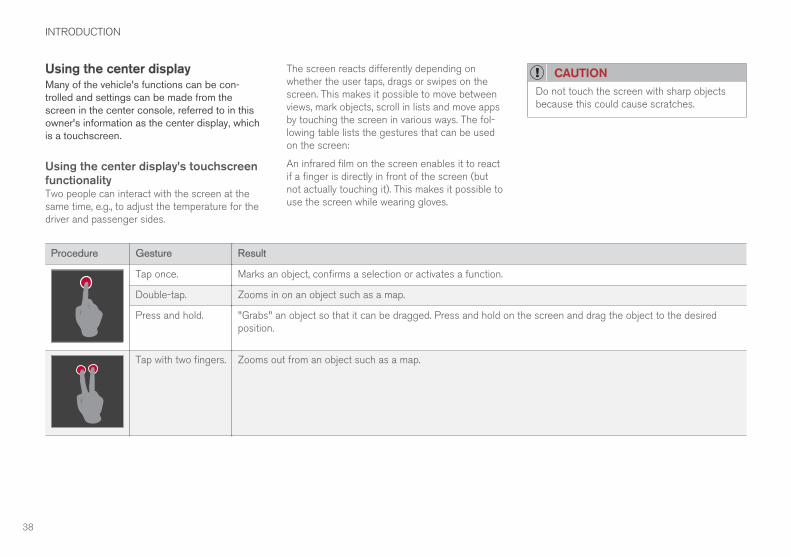
Using the center displayMany of the vehicle's functions can be con-trolled and settings can be made from thescreen in the center console, referred to in thisowner's information as the center display, whichis a touchscreen.
Using the center display's touchscreenfunctionalityTwo people can interact with the screen at thesame time, e.g., to adjust the temperature for thedriver and passenger sides.
The screen reacts differently depending onwhether the user taps, drags or swipes on thescreen. This makes it possible to move betweenviews, mark objects, scroll in lists and move appsby touching the screen in various ways. The fol-lowing table lists the gestures that can be usedon the screen:
An infrared film on the screen enables it to reactif a finger is directly in front of the screen (butnot actually touching it). This makes it possible touse the screen while wearing gloves.
CAUTION
Do not touch the screen with sharp objectsbecause this could cause scratches.
Procedure Gesture Result
Tap once. Marks an object, confirms a selection or activates a function.
Double-tap. Zooms in on an object such as a map.
Press and hold. "Grabs" an object so that it can be dragged. Press and hold on the screen and drag the object to the desiredposition.
Tap with two fingers. Zooms out from an object such as a map.

INTRODUCTION
}}
39
Procedure Gesture Result
Drag Moves between screen views, scrolls in a list, text or a view. Press and hold to drag apps or objects in a list.
Swipe Moves between screen views, scrolls in a list, text or a view
Stretch Zooms in.
Pinch Zooms out.

||
INTRODUCTION
40
Turning off and reactivating the centerdisplay
Home button for the center display
When the center display is turned off, the screengoes dark to avoid disturbing the driver. However,the climate bar remains visible and apps or otherfunctions connected to the display remain active.
1. Press and hold the Home button below thescreen.
> The screen will go dark. However, the cli-mate bar remains visible and apps orother functions connected to the displayremain active. The screen can also becleaned while it is turned off.
2. Reactivate by pressing the Home buttonbriefly.
> The view that was displayed when thescreen was turned off will be displayedagain.
NOTE
• The display cannot be turned off while amessage requiring action is on thescreen.
• The display turns off automatically whenthe ignition is switched off and the driv-er's door is opened.
Returning to Home view1. Press the Home button briefly.
> The most recent Home view mode will bedisplayed.
2. Press again briefly.
> All of the Home view's sub-views willreturn to standard mode.
NOTE
From Home view's standard mode, press theHome button to start animated on-screeninstructions describing how to display the var-ious views.
Moving apps and vehicle functionbuttonsApps and function buttons can be moved andorganized in their respective views.
1. Press and hold an app/button.
> The app/button will change size andbecome transparent. It can then bemoved.
2. Drag the app/button to an available positionin the view.
A maximum of 48 lines can be utilized for placingapps/buttons. To move an app/button outside ofthe visible view, drag it to the bottom of the view.A new line will then be added where the app/button can be placed (this line may not be visi-ble). Swipe the screen to scroll up or down in theview to display information that may be outside ofthe view.
Scrolling in lists, articles or viewsA scroll indicator on the screen shows that it ispossible to scroll up or down in the view. Pressthe indicator and move it up or down or swipe upor down anywhere in the view.
INTRODUCTION
41
The scroll indicator on the right side of the center dis-play
Using center display controls
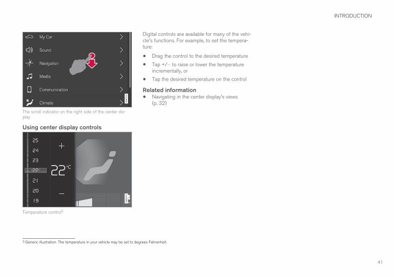
Temperature control3
Digital controls are available for many of the vehi-cle's functions. For example, to set the tempera-ture:
• Drag the control to the desired temperature
• Tap +/− to raise or lower the temperatureincrementally, or
• Tap the desired temperature on the control
Related information• Navigating in the center display's views
(p. 32)
3 Generic illustration. The temperature in your vehicle may be set to degrees Fahrenheit.

INTRODUCTION
42
Using the owner's manualReading your owner's manual is a good way offamiliarizing yourself with the features and sys-tems in your vehicle.
On-board owner's manualReading the owner's manual is a good way tobecome familiar with your vehicle and to learn toutilize the features and functions that it offers.Pay particular attention to the warnings provided.
Volvo reserves the right to make model changesat any time, or to change specifications or designwithout notice and without incurring obligation.
© Volvo Car Corporation
Printed owner's informationWe advise keeping printed owner's information inthe vehicle for quick access to necessary infor-mation and how to contact Volvo if help isrequired.
IllustrationsSome of the illustrations and images used in yourowner's information may be generic and areintended to provide a general view or an exampleof a certain feature or function. The features orfunctions in the illustrations may differ slightlyfrom the equipment in your vehicle depending onthe level of instrumentation or market.
Options and accessoriesOptional or accessory equipment described inthis manual is indicated by an asterisk.
Optional or accessory equipment may not beavailable in all countries or markets. Please notethat some vehicles may be equipped differently,depending on special legal requirements.
Contact your Volvo retailer for additional informa-tion.
FootnotesCertain pages of this manual contain informationin the form of footnotes at the bottom of thepage. This information supplements the text thatthe footnote number refers to (a letter is used ifthe footnote refers to text in a table).
MessagesThere are several displays in the vehicle thatshow messages generated by various systemsand functions in the vehicle. The appearance ofthese texts differs slightly from normal texts (forexample: Phone, Accept).
DecalsThere are various types of decals in the vehiclewhose purpose is to provide important informa-tion in a clear and concise way. The importanceof these decals is explained as follows, indescending order of importance.
Risk of injury
Black ISO symbols on a yellow warning back-ground, white text/image on a black background.Decals of this type are used to indicate potentialdanger. Ignoring a warning of this type couldresult in serious injury or death.

INTRODUCTION
}}
43
Risk of damage to the vehicle
White ISO symbols and white text/image on ablack or blue warning background and space fora message. If the information on decals of thistype is ignored, damage to the vehicle couldresult.
Information
White ISO symbols and white text/image on ablack background. These decals provide generalinformation.
NOTE
The decals shown in the Owner’s Manual areexamples only and are not intended to bereproductions of the decals actually used inthe vehicle. The purpose is to give an indica-tion of how they look and their approximatelocation in the vehicle. The applicable infor-mation for your particular vehicle can befound on the respective decals in the vehicle.
Types of lists
ProceduresProcedures (step-by-step instructions), or actionsthat must be carried out in a certain order, arearranged in numbered lists in this manual.
If there is a series of illustrations associatedwith step-by-step instructions, each step inthe procedure is numbered in the same wayas the corresponding illustration.
Lists in which letters are used can be foundwith series of illustrations in cases where theorder in which the instructions are carried outis not important.
Arrows with or without numbers are used toindicate the direction of a movement.
Arrows containing letters are used to indi-cate movement.
If there are no illustrations associated with astep-by-step list, the steps in the procedure areindicated by ordinary numbers.
Position listsRed circles containing a number are used ingeneral overview illustrations in which certaincomponents are pointed out. The corres-ponding number is also used in the positionlist's description of the various components.
Bullet listsBullets are used to differentiate a number ofcomponents/functions/points of information thatcan be listed in random order.
For example:
• Coolant
• Engine oil
Related informationRelated information offers references to articlescontaining information associated with the infor-mation that you are currently reading.
Continues on next page} }This symbol can be found at the lower rightcorner to indicate that the current topic continueson the following page.

||
INTRODUCTION
44
Continuation from previous page|| This symbol can be found at the upper leftcorner to indicate that the current topic is a con-tinuation from the previous page.
Related information• On-board digital owner's manual (p. 44)
• Owner's manual in mobile devices (p. 14)
• Additional information about your vehicle(p. 8)
On-board digital owner's manualWhen printed owner's information refers to digi-tal owner's information, this is the on-board infor-mation available in the vehicle's center display.
The digital on-board owner's manual is accessed fromthe center display's Top view
There are a number of ways to find information inthe digital owner's manual, which can beaccessed from the manual's top menu by tapping
.
NOTE
The on-board owner's information cannot beaccessed while the vehicle is moving.
Symbols and their descriptions
Takes you to the owner'sinformation start page.
All articles sorted by cate-gory. An article may be lis-ted in several categories.
A selection of useful arti-cles about the most com-monly used functions in thevehicle.

INTRODUCTION
}}
45
Symbols and their descriptions
Exterior/interior views ofthe vehicle in which certainareas/components arehighlighted as hotspots.Tap a hotspot to come to arelevant article.
This offers access to a listof articles that have beensaved as favorites. Tap anarticle to read it in itsentirety.
Symbols and their descriptions
Leads to short instructionalvideos for various vehiclefunctions.
This offers informationabout the current version ofthe owner's information inyour vehicle and other use-ful information.
Related information• Navigating in the digital owner's manual
(p. 45)
Navigating in the digital owner'smanualThe digital on-board owner's manual isaccessed from the center display. The contentsare searchable and it is easy to navigate amongthe various sections.
The digital on-board owner's manual is accessed fromthe center display's Top view
Opening the digital owner's information– To open the digital owner's information, pull
down the center display's Top view and tapOwner's manual.
There are several ways of finding information.
To access the owner's manual's menu, tap in the upper bar.

||
INTRODUCTION
46
Searching using categoriesThe articles in the owner'smanual are structured in mainand sub-categories. The samearticle may appear in severalpertinent categories in order tomake them easier to find.
1. Tap followed by Categories.
> The main categories will be listed.
2. Tap a main category ( ).
> A list of sub-categories and ( ) and arti-
cles ( ) will be displayed.
3. Tap an article to open it. Tap the left arrow togo back.
Interior and exterior hotspotsExterior and interior views ofthe vehicle where certain com-ponents are pointed out arecalled hotspots.
1. Tap followed by Exterior/Interior.
> Exterior/interior views will be displayedwith hotspots, which lead to relevant arti-cles. Swipe the screen horizontally toscroll among the views.
2. Tap a hotspot.
> The title of a relevant article will be dis-played.
3. Tap the title to open the article. Tap the left
arrow to go back or to begin a newsearch.
Quick GuideThe heading Quick Guide inthe owner's manual's menuleads to a selection of articlesthat may be helpful in familiariz-ing you with your vehicle's mostcommon features and func-tions. These articles can also
be found through categories but have been gath-ered here for quick access. Tap an article to readit in its entirety.
FavoritesThis is a list of articles thathave been saved as favorites.Tap an article to read it in itsentirety.
Saving/deleting favoritesSave an article as a favorite by tapping the star
( ) at the upper right when an article is open.
The star symbol will be filled in ( ) when its arti-cle has been saved as a favorite.
To delete a favorite, tap its star again.
VideoTap for short instructional vid-eos for various vehicle func-tions.
InformationTap the symbol for informationabout the current version of theowner's information in yourvehicle and other useful infor-mation.
Start pageTap the symbol to come to theowner's information start page.

INTRODUCTION
* Option/accessory. 47
Using the search function1. Tap the magnifying glass icon ( ) in the
owner's manual's upper menu. A keyboardwill appear at the bottom of the screen.
2. Enter a word, e.g., "seat belt."
> Suggested articles will be displayed asmore characters are entered.
3. Confirm by tapping the article. To leavesearch mode tap the up-arrow next to thesearch box.
Related information• On-board digital owner's manual (p. 44)
Glass
Laminated glassThe windshield and panoramic roof* are made oflaminated glass, which is reinforced to help pre-vent break-ins and to provide additional sound-proofing. Laminated glass is optional for theother side windows.
Laminated glass symbol4
Technician certificationIn addition to Volvo factory training, Volvo sup-ports certification by the National Institute forAutomotive Service Excellence (A.S.E.).
Certified technicians have demonstrated a highdegree of competence in specific areas. Besidespassing exams, each technician must also haveworked in the field for two or more years before acertificate is issued. These professional techni-cians are best able to analyze vehicle problemsand perform the necessary maintenance proce-dures to keep your Volvo at peak operating con-dition.
4 This symbol is not shown on the windshield or panoramic roof.


IMPORTANT INFORMATION

IMPORTANT INFORMATION
50
General safety informationThe vehicle is equipped with a number of safetysystems for the driver and passengers.
In the event of an accident, there are a number ofsensors in the vehicle that react and triggersafety systems such as Roll Stability Control, air-bags, seat belt pretensioners, etc., depending onthe severity of the collision. There are alsomechanical systems such as the WhiplashProtection System.
Warning symbol in the instrument panelThe warning symbol in the instrumentpanel illuminates when the ignition is inmode II or higher. It will go out afterapprox. 6 seconds if no faults are
detected in the airbag system.
WARNING
• If the SRS warning light stays on after theengine has started or if it illuminateswhile you are driving, have the vehicleinspected by a trained and qualified Volvoservice technician as soon as possible.
• Never try to repair any component or partof the SRS yourself. Any interference inthe system could cause malfunction andserious injury. All work on these systemsshould be performed by a trained andqualified Volvo service technician.
If the dedicated warning symbol is notfunctioning, the general warning sym-bol will illuminate instead and the samemessage will be displayed in the instru-
ment panel.
Related information• Safety during pregnancy (p. 52)
• Seat belts (p. 54)
• Airbag system (p. 59)
• Safety mode (p. 68)
• Whiplash protection system (p. 53)
• Child safety (p. 69)
Occupant safetySafety is Volvo's cornerstone.
Volvo's concern for safetyOur concern for safety dates back to 1927 whenthe first Volvo rolled off the production line.Three-point seat belts (a Volvo invention), safetycages, and energy-absorbing impact zones weredesigned into Volvo vehicles long before it wasfashionable or required by government regulation.
We will not compromise our commitment tosafety. We continue to seek out new safety fea-tures and to refine those already in our vehicles.You can help. We would appreciate hearing yoursuggestions about improving automobile safety.We also want to know if you ever have a safetyconcern with your vehicle. Call us in the U.S. at:1-800-458-1552 or in Canada at:1-800-663-8255.

IMPORTANT INFORMATION
}}
51
Occupant safety remindersHow safely you drive doesn't depend on how oldyou are but rather on:
• How well you see.
• Your ability to concentrate.
• How quickly you make decisions understress to avoid an accident.
The following suggestions are intended to helpyou cope with the ever changing traffic environ-ment.
• Never drink and drive.
• If you are taking any medication, consult yourphysician about its potential effects on yourdriving abilities.
• Take a driver-retraining course.
• Have your eyes checked regularly.
• Keep your windshield and headlights clean.
• Replace wiper blades when they start toleave streaks.
• Take into account the traffic, road, andweather conditions, particularly with regard tostopping distance.
• Never send text messages while driving.
• Refrain from using or minimize the use of acell phone while driving.
Related information• Recall information (p. 52)
• Reporting safety defects (p. 51)
Reporting safety defectsThe following information will help you report anyperceived safety-related defects in your vehicle.
Reporting safety defects in the U.S.If you believe that your vehicle has adefect which could cause a crash orcould cause injury or death, you shouldimmediately inform the National High-way Traffic Safety Administration(NHTSA) in addition to notifying VolvoCar USA, LLC. If NHTSA receives simi-lar complaints, it may open an investi-gation, and if it finds that a safetydefect exists in a group of vehicles, itmay order a recall and remedy cam-paign. However, NHTSA cannotbecome involved in individual problemsbetween you, your retailer, or Volvo CarUSA, LLC. To contact NHTSA, you mayeither call the Auto Safety Hotline toll-free at
1-888-327-4236
(TTY: 1-800-424-9153) or write to:NHTSA, U.S. Department of Transpor-tation, Washington D.C. 20590.
You can also obtain other informationabout motor vehicle safety from http://www.safercar.gov, where you can alsoenter your vehicle's VIN (Vehicle Identi-fication Number) to see if it has anyopen recalls.
Volvo strongly recommends that if yourvehicle is covered under a service cam-paign, safety or emission recall or simi-lar action, it should be completed assoon as possible. Please check withyour local retailer or Volvo Car USA,LLC if your vehicle is covered underthese conditions.
NHTSA can be reached at:
Internet:
http://www.nhtsa.gov
Telephone:
1-888-DASH-2-DOT(1-888-327-4236).
Reporting safety defects in CanadaIf you believe your vehicle has a defect that couldcause a crash or could cause injury or death, youshould immediately inform Transport Canada inaddition to notifying Volvo Car Canada Ltd.

||
IMPORTANT INFORMATION
52
Transport Canada can be contacted at:1-800-333-0510
Teletypewriter (TTY): 613 990-4500
Fax: 1-819-994-3372
Mailing Address: Transport Canada - RoadSafety, 80 rue Noël, Gatineau, (Quebec) J8Z 0A1
Related information• Recall information (p. 52)
• Occupant safety (p. 50)
Recall information
On our website, select the "Own" tab on theupper left side of the screen and click the head-ing "Recall Information" on the right side of thescreen. Enter your Vehicle Identification Number(VIN) for your vehicle (found at the base of thewindshield). If your vehicle has any open Recalls,they will be displayed on this page.
You can also enter the Vehicle IdentificationNumber in the search field on the NationalHighway Traffic Safety Administration's (NHTSA)website at: www.nhtsa.gov.
Volvo customers in CanadaFor any questions regarding open recalls for yourvehicle, please contact your authorized Volvoretailer. If your retailer is unable to answer yourquestions, please contact Volvo Customer Rela-tions at 800-663-8255, Monday through Friday,8:30 A.M. to 5:00 P.M. EST or volvocars.com/ca.You may also write us at:
Volvo Car Canada Ltd.
Customer Care Centre
9130 Leslie Street, Suite 101
Richmond Hill, Ontario L4B 0B9
www.tc.gc.ca
Related information• Occupant safety (p. 50)
• Reporting safety defects (p. 51)
Safety during pregnancyThe seat belt should always be worn duringpregnancy. However, it is crucial that it be worncorrectly.
The diagonal section should wrap over the shoul-der then be routed between the breasts and tothe side of the belly. The lap section should layflat over the thighs and as low as possible underthe belly. It must never be allowed to ride upward.Remove all slack from the belt and ensure that itfits close to the body without any twists.
As a pregnancy progresses, pregnant driversshould adjust their seats and steering wheel suchthat they can easily maintain control of the vehi-cle as they drive (which means they must be ableto easily operate the foot pedals and steeringwheel). Within this context, they should strive toposition the seat with as large a distance as pos-sible between their belly and the steering wheel.

IMPORTANT INFORMATION
}}
53
Related information• Buckling and unbuckling seat belts (p. 56)
Whiplash protection systemThe Whiplash protection system (WHIPS) con-sists of specially designed hinges and bracketson the front seat backrests designed to helpabsorb some of the energy generated in a colli-sion from the rear (when the vehicle is rear-ended).
FunctionIn the event of certain rear-end collisions, thehinges and brackets of the front seat backrestsare designed to change position slightly to allowthe backrest/head restraint to help support theoccupant's head before moving slightly rearward.This movement helps absorb some of the forcesthat could result in whiplash.
WARNING
• The WHIPS system is designed to sup-plement the other safety systems in yourvehicle. For this system to function prop-erly, the three-point seat belt must beworn. Please be aware that no systemcan prevent all possible injuries that mayoccur in an accident.
• The WHIPS system is designed to func-tion in certain collisions from the rear,depending on the crash severity, angleand speed.
WARNING
• Occupants in the front seats must neversit out of position. The occupant's backmust be as upright as comfort allows andbe against the seat back with the seatbelt properly fastened.
• If your vehicle has been involved in a rear-end collision, the front seat backrestsmust be inspected by a trained and quali-fied Volvo service technician, even if theseats appear to be undamaged. Certaincomponents in the WHIPS system mayneed to be replaced.
• Do not attempt to service any componentin the WHIPS system yourself.
WARNING
• Boxes, suitcases, etc. wedged behind thefront seats could impede the function ofthe Whiplash Protection System.
• If the rear seat backrests are foldeddown, cargo must be secured to preventit from sliding forward against the frontseat backrests in the event of a collisionfrom the rear. This could interfere withthe action of the Whiplash ProtectionSystem.

||
IMPORTANT INFORMATION
54
Do not place any objects behind the front seats thatcould impede the WHIPS function
WARNING
Any contact between the front seat backrestsand the folded rear seat or a rear-facing childseat could impede the function of the WHIPSsystem. If the rear seat is folded down, theoccupied front seats must be adjusted for-ward so that they do not touch the folded rearseat.
Related information• General safety information (p. 50)
Seat beltsSeat belts should always be worn by all occu-pants of your vehicle. Children should be prop-erly restrained, using an infant, car, or boosterseat determined by age, weight and height.
Most states and provinces make it mandatory foroccupants of a vehicle to use seat belts.
Reversible seat belt pretensionersReversible seat belt pretensioners is a system inthe front seats that pulls the seat belts slightlytaut prior to a collision. This function helps posi-tion the front seat occupants to help improve theeffects of other safety systems, e.g., the airbagsystem.
Seat belt maintenanceCheck periodically that the seat belts are in goodcondition. Use water and a mild detergent forcleaning. Check seat belt mechanism function asfollows: attach the seat belt and pull rapidly onthe strap.
WARNING
• Never repair the belt yourself; have thiswork done by a trained and qualifiedVolvo service technician only.
• Any device used to induce slack into theshoulder belt portion of the three-pointbelt system will have a detrimental effecton the amount of protection available toyou in the event of a collision.
• The seat back should not be tilted too farback. The shoulder belt must be taut inorder to function properly.
• Do not use child safety seats or childbooster cushions/backrests in the frontpassenger's seat. We also recommendthat children who have outgrown thesedevices sit in the rear seat with the seatbelt properly fastened.
Related information• Buckling and unbuckling seat belts (p. 56)
• Door and seat belt reminders (p. 58)
• Seat belt pretensioners (p. 55)

IMPORTANT INFORMATION
55
Seat belt pretensionersThe vehicle's seat belts are equipped with stand-ard and electric pretensioners that can help pullthe seat belts taut in a critical situation or a colli-sion. Some or all of the pretensioners will betriggered in certain types of collisions, depend-ing on the direction and severity of the impact.
Reversible seat belt pretensionersReversible seat belt pretensioners is a system inthe front seats that pulls the seat belts slightlytaut prior to a collision. This function helps posi-tion the front seat occupants to help improve theeffects of other safety systems, e.g., the airbagsystem.
Seat belt pretensioners in collisionsThe seat belts are equipped with standard pre-tensioners that are triggered according to theseverity of a collision.
Seat belt pretensioners in criticalsituationsIn addition to the standard pretensioners, theseat belts in the front seats are also equippedwith electric pretensioners.
The pretensioners interact and can be triggeredalong with the City Safety and Rear CollisionWarning systems. In critical situations such assudden braking, evasive maneuvers, etc., the seatbelt can be pulled taut by the pretensioner'selectric motor.
The electric pretensioner positions the occupantin the seat to help reduce the risk of striking theinterior of the passenger compartment andimproves the effect of other safety systems suchas the airbags.
Resetting the electric pretensionersWhen a critical situation has passed, the seat beltand the electric pretensioner are reset automati-cally.
If the seat belt should remain taut:
1. Stop the vehicle safely.
2. Unbuckle the seat belt and rebuckle it.
> The seat belt and the electric preten-sioner will be reset.
WARNING
• Never repair the belt yourself; have thiswork done by a trained and qualifiedVolvo service technician only.
• Any device used to induce slack into theshoulder belt portion of the three-pointbelt system will have a detrimental effecton the amount of protection available toyou in the event of a collision.
• The seat back should not be tilted too farback. The shoulder belt must be taut inorder to function properly.
• Do not use child safety seats or childbooster cushions/backrests in the frontpassenger's seat. We also recommendthat children who have outgrown thesedevices sit in the rear seat with the seatbelt properly fastened.
Related information• Seat belts (p. 54)
• Door and seat belt reminders (p. 58)
• Buckling and unbuckling seat belts (p. 56)
IMPORTANT INFORMATION
56
Buckling and unbuckling seat beltsSeat belts should be used by all occupants inthe vehicle when it is in motion.
Buckling a seat belt1. Pull the belt out slowly. It should not be twis-
ted or turned.
Be sure that the seat belt in the center posi-tion of the second row of seats is correctlypositioned in the seat belt guide.
NOTE
Each seat belt is equipped with a seat beltretractor that will lock up in the following sit-uations:
• if the belt is pulled out rapidly
• during braking and acceleration
• if the vehicle is leaning excessively
• when driving in turns
• if the Automatic Locking Retractor/Emer-gency Locking Retractor (ALR/ELR) isactivated (each seat belt (except for thedriver's belt) is equipped with theALR/ELR function, which is designed tohelp keep the seat belt taut. ALR/ELRactivates if the seat belt is pulled out as faras possible. If this is done, a sound fromthe seat belt retractor will be audible,which is normal, and the seat belt will bepulled taut and locked in place. This func-tion is automatically disabled when theseat belt is unbuckled and fully retracted).
2. Insert the latch plate into the receptacle. Theseat belt retractor is normally "unlocked" andyou can move freely, provided that the shoul-der belt is not pulled out too far.
> A distinct click will be audible.
WARNING
The seat belt latch plate should only beinserted into its intended receptacle. Insertingit into one of the other receptacles may pre-vent it from functioning properly.

IMPORTANT INFORMATION
}}
57
3. The height of the seat belts in the front seatsand outboard rear seating positions can beadjusted. The height of the shoulder sectionof the seat belt must be correctly adjusted.
Press the button and move the upper seatbelt anchor up or down.
Position it as high as possible so that theshoulder section of the belt is across the seatoccupant's collarbone and not across thethroat.
The seat belt should be positioned over the shoulder(not over the arm)
4. Tighten the lap section of the seat belt bypulling the diagonal section upward towardthe shoulder.
The lap section of the belt must be positioned low on thehips (not pressing against the abdomen)
Make sure that the shoulder belt is rolled upinto its retractor and that the shoulder andlap belts are taut.
WARNING
Never use a seat belt for more than oneoccupant. Never wear the shoulder portion ofthe belt under the arm, behind the back orotherwise out of position. Such use couldcause injury in the event of an accident. Asseat belts lose much of their strength whenexposed to violent stretching, they should bereplaced after any collision, even if theyappear to be undamaged.

||
IMPORTANT INFORMATION
58
Unbuckling the seat beltTo remove the seat belt, press the red section onthe seat belt receptacle. Before exiting the vehi-cle, check that the seat belt retracts fully afterbeing unbuckled. If necessary, guide the beltback into the retractor slot.
Be sure that the seat belt in the center positionof the second row of seats is correctly positionedin the seat belt guide.
Related information• Door and seat belt reminders (p. 58)
• Seat belts (p. 54)
Door and seat belt remindersThe door and seat belt reminders are intendedto alert all occupants of the vehicle that theirseat belts should be buckled before the vehiclebegins to move or if a door, the hood, tailgate orfuel filler door have not been closed properly.
Graphics in the instrument panel
Warning colors for doors/tailgate vary depending on thevehicle's speed (generic illustration)
The instrument panel graphic shows the seatswhere seat belts are not buckled.
The same graphic also indicates if a door, thehood, tailgate or fuel filler door is/are open.
This graphic disappears automatically afterapprox. 6 seconds or if the if the O button on thesteering wheel keypad is pressed.
Seat belt reminder
Seat belt reminder light in ceiling console
The seat belt reminder consists of anaudible signal, an indicator light nearthe rearview mirror and a symbol in theinstrument panel that alert all occu-
pants of the vehicle to buckle their seat belts.
The audible signal is speed-dependent and willsound for several seconds.
If the driver's or a passenger's seat belt is notbuckled, this will be indicated in the instrumentpanel.
Child seats are not included in the seat beltreminder system.
Front seatsAn audible signal and an indicator light willremind the driver and front seat passenger tobuckle their seat belts.

IMPORTANT INFORMATION
59
Rear seatsThe rear seat belt reminder has two functions.
• It indicates which seat belts are buckled inthe rear seats. This will also be displayed inan instrument panel graphic. This graphiccan be erased by pressing the O button onthe steering wheel keypad.
• It also provides audio and visual reminders ifa rear seat belt is unbuckled while the vehi-cle is in motion. The reminders will disappearwhen the seat belt has been buckled again.
Door/hood/tailgate/fuel filler doorreminderIf a door, the hood, tailgate or fuel filler dooris/are not properly closed, this will be indicated ina graphic in the instrument panel. Stop the vehi-cle safely and close the source of the reminder.
If the vehicle is moving at a speedunder approx.6 mph (10 km/h), theinformation symbol will illuminate in theinstrument panel.
At speeds above approx. 6 mph(10 km/h), the warning symbol will illu-minate in the instrument panel.
Related information• Seat belts (p. 54)
• Buckling and unbuckling seat belts (p. 56)
• Seat belt pretensioners (p. 55)
Airbag systemAs an enhancement to the three-point seat belts,your vehicle is equipped with an airbag system.
WARNING
• If the airbag warning light stays on afterthe engine has started or if it illuminateswhile you are driving, have the vehicleinspected by a trained and qualified Volvoservice technician as soon as possible.
• Never try to repair any component or partof the airbag systems yourself. Any inter-ference in the system could cause mal-function and serious injury. All work onthese systems should be performed by atrained and qualified Volvo service techni-cian.
WARNING
If your vehicle has become flood-damaged inany way (e.g., soaked carpeting/standingwater on the floor of the vehicle), do notattempt to start the vehicle. This may causeairbag deployment which could result in seri-ous injury. Have the vehicle towed to a trainedand qualified Volvo service technician forrepairs.
Before attempting to tow the vehicle:
1. Switch off the ignition for at least10 minutes and disconnect the battery.
2. Follow the instructions in the digital own-ers' information for manually overridingthe shiftlock system.
Deployed airbags
WARNING
If any of the airbags have deployed:
• Do not attempt to drive the vehicle. Haveit towed to a qualified repair facility.
• If necessary seek medical attentIon.

IMPORTANT INFORMATION
60
Driver/passenger side airbagsThe front airbags supplement the three-pointseat belts. For these airbags to provide the pro-tection intended, seat belts must be worn at alltimes.
Driver and passenger side front airbags
The front airbag systemThe front airbag system includes gas generatorssurrounded by the airbags, and deceleration sen-sors that activate the gas generators, causing theairbags to be inflated with nitrogen gas.
As the movement of the seats' occupants com-presses the airbags, some of the gas is expelledat a controlled rate to provide better cushioning.Both seat belt pretensioners also deploy, mini-mizing seat belt slack. The entire process, includ-ing inflation and deflation of the airbags, takesapproximately one fifth of a second.
The location of the front airbags is indicated bySRS AIRBAG embossed on the steering wheelpad and above the glove compartment, and bydecals on both sun visors and on the front andfar right side of the dash.
The driver's side front airbag is folded andlocated in the steering wheel hub.
The knee airbag is folded on the underside ofthe dashboard on the driver's side. The textAIRBAG is embossed on the panel.
The passenger's side front airbag is foldedbehind a panel located above the glove compart-ment.
WARNING
• The airbags in the vehicle are designed tobe a SUPPLEMENT to–not a replace-ment for–the three-point seat belts. Formaximum protection, wear seat belts at alltimes. Be aware that no system can pre-vent all possible injuries that may occur inan accident.
• Never drive with your hands on the steer-ing wheel pad/airbag housing.
• The front airbags are designed to helpprevent serious injury. Deployment occursvery quickly and with considerable force.During normal deployment and depend-ing on variables such as seating position,one may experience abrasions, bruises,swellings, or other injuries as a resultfrom deployment of one or both of theairbags.
• When installing any accessory equipment,make sure that the front airbag system isnot damaged. Any interference in the sys-tem could cause malfunction.
Front airbag deployment• The front airbags are designed to deploy dur-
ing certain frontal or front-angular collisions,impacts, or decelerations, depending on thecrash severity, angle, speed and objectimpacted. The airbags may also deploy in

IMPORTANT INFORMATION
}}
61
certain non-frontal collisions where rapiddeceleration occurs.
• The airbag system sensors, which trigger thefront airbags, are designed to react to boththe impact of the collision and the inertialforces generated by it, and to determine ifthe intensity of the collision is sufficient forthe seat belt pretensioners and/or airbags tobe deployed.
However, not all frontal collisions activate thefront airbags.
• If the collision involves a nonrigid object (e.g.,a snow drift or bush), or a rigid, fixed objectat a low speed, the front airbags will not nec-essarily deploy.
• Front airbags do not normally deploy in aside impact collision, in a collision from therear or in a rollover situation.
• The amount of damage to the bodyworkdoes not reliably indicate if the airbagsshould have deployed or not.
NOTE
• Deployment of front airbags occurs onlyone time during an accident. In a collisionwhere deployment occurs, the airbagsand seat belt pretensioners activate.Some noise occurs and a small amountof powder is released. The release of thepowder may appear as smoke-like matter.This is a normal characteristic and doesnot indicate fire.
• Volvo's front airbags use special sensorsthat are integrated with the front seatbuckles. The point at which the airbagdeploys is determined by whether or notthe seat belt is being used, as well as theseverity of the collision.
• Collisions can occur where only one ofthe airbags deploys. If the impact is lesssevere, but severe enough to present aclear injury risk, the airbags are triggeredat partial capacity. If the impact is moresevere, the airbags are triggered at fullcapacity.
WARNING
• Do not use child safety seats or childbooster cushions/backrests in the frontpassenger's seat. We also recommendthat occupants under 4 feet 7 inches(140 cm) in height who have outgrownthese devices sit in the rear seat with theseat belt fastened. See also the Occu-pant Weight Sensor information.
• Never drive with the airbags deployed.The fact that they hang out can impair thesteering of your vehicle. Other safety sys-tems can also be damaged.
• The smoke and dust formed when theairbags are deployed can cause skin andeye irritation in the event of prolongedexposure.
Should you have questions about any componentin the SRS system, please contact a trained andqualified Volvo service technician or Volvo cus-tomer support:
In the USA
Volvo Car USA, LLC
Customer Care Center
1 Volvo Drive
P.O. Box 914
Rockleigh, New Jersey 07647

||
IMPORTANT INFORMATION
62
1-800-458-1552
www.volvocars.com/us
In Canada
Volvo Car Canada Ltd.
Customer Care Centre
9130 Leslie Street, Suite 101
Richmond Hill, Ontario L4B 0B9
1-800-663-8255
www.volvocars.com/ca
Airbag decals
Airbag decal on the outside of both sun visors
Passenger's side airbag decal
WARNING
• Children must never be allowed in thefront passenger's seat.
• Occupants in the front passenger's seatmust never sit on the edge of the seat, sitleaning toward the instrument panel orotherwise sit out of position.
• The occupant's back must be as uprightas comfort allows and be against the seatback with the seat belt properly fastened.
• Feet must be on the floor, e.g., not on thedash, seat or out of the window.
WARNING
• No objects or accessory equipment, e.g.dashboard covers, may be placed on,attached to, or installed near the air baghatch (the area above the glove compart-ment) or the area affected by airbagdeployment.
• There should be no loose articles, suchas coffee cups on the floor, seat, or dash-board area.
• Never try to open the airbag cover on thesteering wheel or the passenger's sidedashboard. This should only be done by atrained and qualified Volvo service techni-cian.
• Failure to follow these instructions canresult in injury to the vehicle occupants.
Related information• Seat belts (p. 54)
• Occupant weight sensor (p. 63)

IMPORTANT INFORMATION
}}
63
Occupant weight sensorThe Occupant Weight Sensor (OWS) isdesigned to meet the regulatory requirements ofFederal Motor Vehicle Safety Standard (FMVSS)208 and is designed to disable (will not inflate)the passenger's side front airbag under certainconditions.
Occupant Weight Sensor (OWS) indicator light
Disabling the passenger's side frontairbagVolvo recommends that ALL occupants (adultsand children) shorter than 4 feet 7 inches(140 cm) be seated in the back seat of any vehi-cle with a front passenger side airbag and beproperly restrained for their size and weight.
The OWS works with sensors that are part of thefront passenger's seat and seat belt. The sensorsare designed to detect the presence of a properly
seated occupant and determine if the passeng-er's side front airbag should be enabled (mayinflate) or disabled (will not inflate).
The OWS will disable (will not inflate) the pas-senger's side front airbag when:
• the front passenger's seat is unoccupied, orhas small/medium objects in the front seat,
• the system determines that an infant is pres-ent in a rear-facing infant seat that is instal-led according to the manufacturer's instruc-tions,
• the system determines that a small child ispresent in a forward-facing child restraintthat is installed according to the manufactur-er's instructions,
• the system determines that a small child ispresent in a booster seat,
• a front passenger takes his/her weight off ofthe seat for a period of time,
• a child or a small person occupies the frontpassenger's seat.
The OWS uses a PASSENGER AIRBAG OFFindicator lamp which will illuminate and stay on toremind you that the passenger's side front airbagis disabled. The PASSENGER AIRBAG OFF indi-cator lamp is located in the overhead console,near the base of the rearview mirror.
NOTE
When the ignition is switched on, the OWSindicator light will illuminate for several sec-onds while the system performs a self-diag-nostic test.
However, if a fault is detected in the system:
• The OWS indicator light will stay on
• The SRS warning light will come on and stayon and a text message will be displayed.
WARNING
If a fault in the system is detected and indi-cated as described, be aware that the pas-senger's side front airbag will not deploy inthe event of a collision. In this case, the SRSsystem and Occupant Weight Sensor shouldbe inspected by a trained and qualified Volvoservice technician as soon as possible.

||
IMPORTANT INFORMATION
64
WARNING
• Never try to open, remove, or repair anycomponents in the OWS system. Thiscould result in system malfunction. Main-tenance or repairs should only be carriedout by an a trained and qualified Volvoservice technician.
• The front passenger's seat should not bemodified in any way. This could reducepressure on the seat cushion, whichmight interfere with the OWS system'sfunction.
Passenger's
seat occu-
pancy status
OWS indi-
cator light
status
Passenger's
side front air-
bag status
Seat unoccu-pied
OWS indi-cator lightlights up.
Passenger'sside front air-bag disabled
Seat occu-pied by lowweight occu-pant/objectA
OWS indi-cator lightlights up
Passenger'sside front air-bag disabled
Seat occu-pied by heavyoccupant/object
OWS indi-cator light isnot lit
Passenger'sside front air-bag enabled
A Volvo recommends that children always be properly restrainedin appropriate child restraints in the rear seats. Do not assumethat the passenger's side front airbag is disabled unless thePASSENGER AIRBAG OFF indicator lamp is lit. Make sure thechild restraint is properly installed. If there is any doubt as to thestatus of the passenger's side front airbag, move the childrestraint to the rear seat.
The OWS is designed to enable (may inflate) thepassenger's side front airbag in the event of acollision anytime the system senses that a per-son of adult size is sitting properly in the frontpassenger's seat. The PASSENGER AIRBAGOFF indicator lamp will be off and remain off.
If a person of adult size is sitting in the front pas-senger's seat, but the PASSENGER AIRBAGOFF indicator lamp is on, it is possible that the
person isn't sitting properly in the seat. If thishappens:
• Turn the vehicle off and ask the person toplace the seatback in an upright position.
• Have the person sit upright in the seat, cen-tered on the seat cushion, with the person'slegs comfortably extended.
• Restart the vehicle and have the personremain in this position for about two minutes.This will allow the system to detect that per-son and enable the passenger's frontal air-bag.
• If the PASSENGER AIRBAG OFF indicatorlamp remains on even after this, the personshould be advised to ride in the rear seat.
This condition reflects limitations of the OWSclassification capability. It does not indicate OWSmalfunction.
ModificationsIf you are considering modifying your vehicle inany way to accommodate a disability, for exampleby altering or adapting the driver's or front pas-senger's seat(s) and/or airbag systems, pleasecontact Volvo at:
In the USA
Volvo Car USA, LLC
Customer Care Center
1 Volvo Drive
IMPORTANT INFORMATION
}}
65
P.O. Box 914
Rockleigh, New Jersey 07647
1-800-458-1552
In Canada
Volvo Car Canada Ltd.
Customer Care Centre
9130 Leslie Street, Suite 101
Richmond Hill, Ontario L4B 0B9
1-800-663-8255
WARNING
• No objects that add to the total weight onthe seat should be placed on the frontpassenger's seat. If a child is seated inthe front passenger's seat with any addi-tional weight, this extra weight couldcause the OWS system to enable the air-bag, which might cause it to deploy in theevent of a collision, thereby injuring thechild.
• The seat belt should never be wrappedaround an object on the front passeng-er's seat. This could interfere with theOWS system's function.
• The front passenger's seat belt shouldnever be used in a way that exerts morepressure on the passenger than normal.This could increase the pressure exertedon the weight sensor by a child, andcould result in the airbag being enabled,which might cause it to deploy in theevent of a collision, thereby injuring thechild.
WARNING
• Keep the following points in mind withrespect to the OWS system. Failure tofollow these instructions could adverselyaffect the system's function and result inserious injury to the occupant of the frontpassenger's seat:
• The full weight of the front seat passen-ger should always be on the seat cushion.The passenger should never lift him/herself off the seat cushion using thearmrest in the door or the center console,by pressing the feet on the floor, by sit-ting on the edge of the seat cushion, orby pressing against the backrest in a waythat reduces pressure on the seat cush-ion. This could cause OWS to disable thefront, passenger's side airbag.

||
IMPORTANT INFORMATION
66
WARNING
• Do not place any type of object on thefront passenger's seat in such a way thatjamming, pressing, or squeezing occursbetween the object and the front seat,other than as a direct result of the correctuse of the Automatic Locking Retractor/Emergency Locking Retractor (ALR/ELR)seat belt.
• No objects should be placed under thefront passenger's seat. This could inter-fere with the OWS system's function.
Related information• Airbag system (p. 59)
Side impact airbagsAs an enhancement to the structural side impactprotection built into your vehicle, it is also equip-ped with Side Impact Protection System (SIPS)airbags.
The SIPS airbag system is designed to helpincrease occupant protection in the event of cer-tain side impact collisions. The SIPS airbags aredesigned to deploy only during certain side-impact collisions, depending on the crashseverity, angle, speed and point of impact.
NOTE
SIPS airbag deployment (one airbag) occursonly on the side of the vehicle affected by theimpact. The airbags are not designed todeploy in all side impact situations.
Components in the SIPS airbag systemThis SIPS airbag system consists of a gas gener-ator, the side airbag modules built into the out-board sides of both front seat backrests, andelectronic sensors/wiring.

IMPORTANT INFORMATION
67
WARNING
• The SIPS airbag system is a supplementto the structural Side Impact ProtectionSystem and the three-point seat belt sys-tem. It is not designed to deploy duringcollisions from the front or rear of thevehicle or in rollover situations.
• The use of seat covers on the front seatsmay impede SIPS airbag deployment.
• No objects, accessory equipment or stick-ers may be placed on, attached to orinstalled near the SIPS airbag system orin the area affected by SIPS airbagdeployment.
• Never try to open or repair any compo-nents of the SIPS airbag system. Thisshould be done only by a trained andqualified Volvo service technician.
• In order for the SIPS airbag to provide itsbest protection, both front seat occupantsshould sit in an upright position with theseat belt properly fastened.
• Failure to follow these instructions canresult in injury to the occupants of thevehicle in the event of an accident.
Related information• Airbag system (p. 59)
• Seat belts (p. 54)
Inflatable curtainsThe inflatable curtain is designed to help protectthe heads of the occupants of the front seatsand the occupant of the outboard rear seatingpositions in certain side impact collisions.
This system consists of inflatable curtains locatedalong the sides of the roof liners, stretching fromthe center of both front side windows to the rearedge of the rear side door windows.
In certain side impacts, both the Inflatable Cur-tain (IC) and the side Impact Airbag System(SIPS airbag) will deploy. The IC and the SIPSairbag deploy simultaneously.
WARNING
• Never try to open or repair any compo-nents of the IC system. This should bedone only by a trained and qualified Volvoservice technician.
• Never hang heavy items from the ceilinghandles. This could impede deploymentof the Inflatable Curtain.
• The cargo compartment and rear seatshould not be loaded to a level higherthan 4 in. (10 cm) below the upper edgeof the rear side windows. Objects placedhigher than this level could impede thefunction of the Inflatable Curtain.
• In order for the IC to provide its best pro-tection, both front seat occupants andboth outboard rear seat occupants shouldsit in an upright position with the seat beltproperly fastened; adults using the seatbelt and children using the proper childrestraint system.
Related information• Airbag system (p. 59)
• Side impact airbags (p. 66)
• Child safety (p. 69)
• Seat belts (p. 54)
IMPORTANT INFORMATION
68
Safety modeAs a safety precaution after a collision, the func-tionality of some of the vehicle's systems may bereduced.
If the vehicle has been involved in a collision, thetext Safety mode may appear in the informationdisplay.
NOTE
This text can only be shown if the display isundamaged and the vehicle's electrical sys-tem is intact.
Safety mode is a feature that is triggered if oneor more of the safety systems such as the front/side airbags inflatable curtain, etc., or one ormore of the seat belt pretensioners has deployed.The collision may have damaged an importantfunction in the vehicle, such as the fuel lines,sensors for one of the safety systems, the brakesystem, etc.
WARNING
• Never attempt to repair the vehicle your-self or to reset the electrical system afterthe vehicle has displayed Safety mode.This could result in injury or improper sys-tem function.
• Restoring the vehicle to normal operatingstatus should only be done by a trainedand qualified Volvo service technician.
• After Safety mode has been displayed, ifyou detect the odor of fuel vapor, or seeany signs of fuel leakage, do not attemptto start the vehicle. Leave the vehicleimmediately.
Related information• Starting or moving a vehicle in safety mode
(p. 68)
• General safety information (p. 50)
Starting or moving a vehicle insafety modeIf Safety mode has been set, it may be possibleto start and move the vehicle, for example, if it isblocking traffic.
Starting the vehicle in safety mode1. Check the vehicle for damage, particularly for
fuel leakage or the smell of gasoline fumes.
If the damage to the vehicle is minor andthere is no fuel leakage/fumes, you mayattempt to start the engine and move thevehicle.
WARNING
If you smell gasoline fumes or detect fuelleakage while Safety mode See Owner'smanual is displayed in the instrument panel,do not attempt to start the vehicle. Leavethe vehicle immediately.
2. Turn the start knob clockwise as far as possi-ble and release it.
3. Try to start the vehicle.
> Vehicle start System check, wait willbe displayed in the instrument panel whilethe vehicle's electrical system attempts toreset to normal mode.

IMPORTANT INFORMATION
}}
69
WARNING
If the message Safety mode See Owner'smanual is still displayed, the vehicle shouldnot be driven and must be towed. Concealedfaults may make the vehicle difficult to control.
Moving the vehicle after safety modehas been setIf the message Normal mode The vehicle isnow in normal mode is displayed, the vehiclemay be moved carefully from its present positionif, for example, it is blocking traffic.
It should, however, not be moved farther thanis absolutely necessary.
WARNING
After Safety mode has been set, the vehicleshould not be driven or towed (pulled on theground by another vehicle). It must be trans-ported on a flatbed tow truck to a trained andqualified Volvo service technician for inspec-tion/repairs.
Related information• Safety mode (p. 68)
Child safetyChildren should always be seated safely whentraveling in the vehicle.
General informationVolvo recommends the proper use of restraintsystems for all occupants including children.Remember that, regardless of age and size, achild should always be properly restrained in avehicle.
Your vehicle is also equipped with ISOFIX/LATCH attachments, which make it more conven-ient to install child seats.
Some restraint systems for children are designedto be secured in the vehicle by lap belts or thelap portion of a lap-shoulder belt. Such childrestraint systems can help protect children invehicles in the event of an accident only if theyare used properly. However, children could beendangered in a crash if the child restraints arenot properly secured in the vehicle. Failure to fol-low the installation instructions for your childrestraint can result in your child striking the vehi-cle's interior in a sudden stop.
Holding a child in your arms is NOT a suitablesubstitute for a child restraint system. In an acci-dent, a child held in a person's arms can becrushed between the vehicle's interior and anunrestrained person. The child could also beinjured by striking the interior, or by being ejectedfrom the vehicle during a sudden maneuver or
impact. The same can also happen if the infant orchild rides unrestrained on the seat. Other occu-pants should also be properly restrained to helpreduce the chance of injuring or increasing theinjury of a child.
All states and provinces have legislation govern-ing how and where children should be carried ina vehicle. Find out the regulations existing in yourstate or province. Recent accident statistics haveshown that children are safer in rear seatingpositions than front seating positions when prop-erly restrained. A child restraint system can helpprotect a child in a vehicle. Here's what to lookfor when selecting a child restraint system:
It should have a label certifying that it meetsapplicable Federal Motor Vehicle Safety Stand-ards (FMVSS 213) – or in Canada, CMVSS 213.
Make sure the child restraint system is approvedfor the child's height, weight and development –the label required by the standard or regulation,or instructions for infant restraints, typically pro-vide this information.
In using any child restraint system, we urge youto carefully look over the instructions that areprovided with the restraint. Be sure you under-stand them and can use the device properly andsafely in this vehicle. A misused child restraintsystem can result in increased injuries for boththe infant or child and other occupants in thevehicle.

||
IMPORTANT INFORMATION
* Option/accessory.70
When a child has outgrown the child safety seat,you should use the rear seat with the standardseat belt fastened. The best way to help protectthe child here is to place the child on a cushionso that the seat belt is properly located on thehips. Legislation in your state or province maymandate the use of a child seat or cushion incombination with the seat belt, depending on thechild's age and/or size. Please check local regu-lations.
A specially designed and tested booster cushionand backrest can be obtained from your Volvoretailer. See also the article "Integrated boostercushion."
WARNING
• Do not use child safety seats or childbooster cushions/backrests in the frontpassenger's seat. We also recommendthat children under 4 feet 7 inches(140 cm) in height who have outgrownthese devices sit in the rear seat with theseat belt fastened.
• On hot days, the temperature in the vehi-cle interior can rise very quickly. Exposureto these high temperatures for even ashort period of time can cause heat-rela-ted injury or death. Small children are par-ticularly at risk. Never leave children unat-tended in a vehicle.
Child seats should always be registered.
Volvo's recommendationsWhy does Volvo believe that no child should sit inthe front seat of a car? It's quite simple really. Afront airbag is a very powerful device designed,by law, to help protect an adult.
Because of the size of the airbag and its speedof inflation, a child should never be placed in thefront seat, even if he or she is properly belted orstrapped into a child safety seat. Volvo has beenan innovator in safety for over seventy-five years,and we'll continue to do our part. But we needyour help. Please remember to put your childrenin the back seat, and buckle them up.
WARNING
A child restraint should never be reused if:
• The vehicle has been involved in a colli-sion, no matter how minor
• Its history is unknown
• It is older than the manufacturer's expira-tion date
Volvo has some very specificrecommendations
• Always wear your seat belt.
• Airbags are a SUPPLEMENTAL safetydevice which, when used with a three-pointseat belt can help reduce serious injuriesduring certain types of accidents. Volvo rec-ommends that you do not disconnect the air-bag system in your vehicle.
• Volvo strongly recommends that everyone inthe vehicle be properly restrained.
• Volvo recommends that ALL occupants(adults and children) shorter than 4 feet7 inches (140 cm) be seated in the backseat of any vehicle with a front passengerside airbag.
• Drive safely!
Related information• Integrated booster cushion* (p. 81)
• Booster cushions (p. 77)
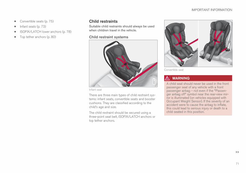
IMPORTANT INFORMATION
}}
71
• Convertible seats (p. 75)
• Infant seats (p. 73)
• ISOFIX/LATCH lower anchors (p. 78)
• Top tether anchors (p. 80)
Child restraintsSuitable child restraints should always be usedwhen children travel in the vehicle.
Child restraint systems
Infant seat
There are three main types of child restraint sys-tems: infant seats, convertible seats and boostercushions. They are classified according to thechild's age and size.
The child restraint should be secured using athree-point seat belt, ISOFIX/LATCH anchors ortop tether anchors.
Convertible seat
WARNING
A child seat should never be used in the frontpassenger seat of any vehicle with a frontpassenger airbag – not even if the "Passen-ger airbag off" symbol near the rear-view mir-ror is illuminated (on vehicles equipped withOccupant Weight Sensor). If the severity of anaccident were to cause the airbag to inflate,this could lead to serious injury or death to achild seated in this position.

||
IMPORTANT INFORMATION
72
Booster cushion
WARNING
Always refer to the child restraint manufactur-er's instructions for detailed information onsecuring the restraint.
WARNING
• When not in use, keep the child restraintsystem secured or remove it from thepassenger compartment to help prevent itfrom injuring passengers in the event of asudden stop or collision.
• A small child's head represents a consid-erable part of its total weight and its neckis still very weak. Volvo recommends thatchildren up to age 4 travel, properlyrestrained, facing rearward. In addition,Volvo recommends that children shouldride rearward facing, properly restrained,as long as possible.
Automatic Locking Retractor/Emergency Locking Retractor (ALR/ELR)To make child seat installation easier, each seatbelt (except for the driver's belt) is equipped witha locking mechanism to help keep the seat belttaut.
When attaching the seat belt to a child seat:1. Attach the seat belt to the child seat accord-
ing to the child seat manufacturer's instruc-tions.
2. Pull the seat belt out as far as possible.
3. Insert the seat belt latch plate into the buckle(lock) in the usual way.
4. Release the seat belt and pull it taut aroundthe child seat.
A sound from the seat belt retractor will be audi-ble at this time and is normal. The belt will nowbe locked in place. This function is automaticallydisabled when the seat belt is unlocked and thebelt is fully retracted.
WARNING
Do not use child safety seats or child boostercushions/backrests in the front passenger'sseat. We also recommend that children whohave outgrown these devices sit in the rearseat with the seat belt properly fastened.
Child restraint registration and recallsChild restraints could be recalled for safety rea-sons. You must register your child restraint to bereached in a recall. To stay informed about childsafety seat recalls, be sure to fill out and returnthe registration card that comes with new childrestraints.
Child restraint recall information is readily availa-ble in both the U.S. and Canada. For recall infor-mation in the U.S., call the U.S. Government'sAuto Safety Hotline at 1-800-424-9393 or go tohttp://www-odi.nhtsa.dot.gov/cars/problems/recalls/register/childseat/index.cfm. In Canada,visit Transport Canada's Child Safety website athttp://www.tc.gc.ca/roadsafety/childsafety/menu.htm.

IMPORTANT INFORMATION
}}
73
Infant seatsSuitable child restraints should always be usedwhen children (depending on their age/size) areseated in the vehicle.
Securing an infant seat with a seat belt
Do not place the infant seat in the front passenger'sseat
1. Place the infant seat in the rear seat of thevehicle.
2. Attach the seat belt to the infant seataccording to the manufacturer's instructions.
Positioning the seat belt through the infant seat
WARNING
• An infant seat must be in the rear-facingposition only.
• The infant seat should not be positionedbehind the driver's seat unless there isadequate space for safe installation.
WARNING
A child seat should never be used in the frontpassenger seat of any vehicle with a frontpassenger airbag – not even if the "Passen-ger airbag off" symbol near the rear-view mir-ror is illuminated (on vehicles equipped withOccupant Weight Sensor). If the severity of anaccident were to cause the airbag to inflate,this could lead to serious injury or death to achild seated in this position.
3.
Fasten the seat belt
Fasten the seat belt by inserting the latchplate into the buckle (lock) until a distinctclick is audible.
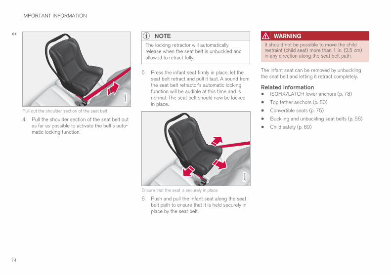
||
IMPORTANT INFORMATION
74
Pull out the shoulder section of the seat belt
4. Pull the shoulder section of the seat belt outas far as possible to activate the belt's auto-matic locking function.
NOTE
The locking retractor will automaticallyrelease when the seat belt is unbuckled andallowed to retract fully.
5. Press the infant seat firmly in place, let theseat belt retract and pull it taut. A sound fromthe seat belt retractor's automatic lockingfunction will be audible at this time and isnormal. The seat belt should now be lockedin place.
Ensure that the seat is securely in place
6. Push and pull the infant seat along the seatbelt path to ensure that it is held securely inplace by the seat belt.
WARNING
It should not be possible to move the childrestraint (child seat) more than 1 in. (2.5 cm)in any direction along the seat belt path.
The infant seat can be removed by unbucklingthe seat belt and letting it retract completely.
Related information• ISOFIX/LATCH lower anchors (p. 78)
• Top tether anchors (p. 80)
• Convertible seats (p. 75)
• Buckling and unbuckling seat belts (p. 56)
• Child safety (p. 69)

IMPORTANT INFORMATION
}}
75
Convertible seatsSuitable child restraints should always be usedwhen children (depending on their age/size) areseated in the vehicle.
Securing a convertible seat with a seatbelt
Do not place the convertible seat in the front passeng-er's seat
Convertible seats can be used in either a forwardor rearward-facing position, depending on theage and size of the child.
Route the seat belt through the convertible seat
WARNING
Always use a convertible seat that is suitablefor the child's age and size. See the converti-ble seat manufacturer's recommendations.
1. Place the convertible seat in the rear seat ofthe vehicle.
WARNING
• A small child's head represents a consider-able part of its total weight and its neck isstill very weak. Volvo recommends thatchildren up to age 4 travel, properlyrestrained, facing rearward. In addition,Volvo recommends that children shouldride rearward facing, properly restrained, aslong as possible.
• Convertible child seats should be installedin the rear seat only.
• A rear-facing convertible seat should notbe positioned behind the driver's seatunless there is adequate space for safeinstallation.
2. Attach the seat belt to the convertible seataccording to the manufacturer's instructions.

||
IMPORTANT INFORMATION
76
Fasten the seat belt
3. Fasten the seat belt by inserting the latchplate into the buckle (lock) until a distinctclick is audible.
4. Pull the shoulder section of the seat belt outas far as possible to activate the belt's auto-matic locking function.
NOTE
The locking retractor will automaticallyrelease when the seat belt is unbuckled andallowed to retract fully.
5. Press the convertible seat firmly in place, letthe seat belt retract and pull it taut. A soundfrom the seat belt retractor's automatic lock-ing function will be audible at this time and isnormal. The seat belt should now be lockedin place.
Pull out the shoulder section of the seat belt
6. Push and pull the convertible seat along theseat belt path to ensure that it is heldsecurely in place by the seat belt.
WARNING
It should not be possible to move the childrestraint (child seat) more than 1 in. (2.5 cm)in any direction along the seat belt path.
The convertible seat can be removed by unbuck-ling the seat belt and letting it retract completely.
Ensure that the seat is securely in place
WARNING
A child seat should never be used in the frontpassenger seat of any vehicle with a frontpassenger airbag – not even if the "Passen-ger airbag off" symbol near the rear-view mir-ror is illuminated. If the severity of an accidentwere to cause the airbag to inflate, this couldlead to serious injury or death to a childseated in this position.

IMPORTANT INFORMATION
}}
77
Related information• ISOFIX/LATCH lower anchors (p. 78)
• Top tether anchors (p. 80)
• Booster cushions (p. 77)
• Buckling and unbuckling seat belts (p. 56)
• Child safety (p. 69)
Booster cushions
Securing a booster cushion
Position the child correctly on the booster cushion
Booster cushions are recommended for childrenwho have outgrown convertible seats.
1. Place the booster cushion in the rear seat ofthe vehicle.
2. With the child properly seated on the boostercushion, attach the seat belt to or around thecushion according to the manufacturer'sinstructions.
3. Fasten the seat belt by inserting the latchplate into the buckle (lock) until a distinctclick is audible.
Positioning the seat belt
4. Ensure that the seat belt is pulled taut andfits snugly around the child.
WARNING
• The hip section of the three-point seatbelt must fit snugly across the child'ships, not across the stomach.
• The shoulder section of the three-pointseat belt should be positioned across thechest and shoulder.
• The shoulder belt must never be placedbehind the child's back or under the arm.

||
IMPORTANT INFORMATION
* Option/accessory.78
Related information• ISOFIX/LATCH lower anchors (p. 78)
• Top tether anchors (p. 80)
• Child safety (p. 69)
• Buckling and unbuckling seat belts (p. 56)
• Integrated booster cushion* (p. 81)
ISOFIX/LATCH lower anchorsLower anchors for ISOFIX/LATCH-equippedchild seats are located in the second row, out-board seats, hidden below the backrest cush-ions.
Using the ISOFIX/LATCH lower childseat anchors
Location of the ISOFIX/LATCH anchors
Symbols on the seat back upholstery mark theISOFIX/LATCH anchor positions as shown. Toaccess the anchors, kneel on the seat cushionand locate the anchors by feel. Always follow yourchild seat manufacturer's installation instructions,and use both ISOFIX/LATCH lower anchors andtop tethers whenever possible.
To access the anchors1. Put the child restraint in position.
2. Kneel on the child restraint to press downthe seat cushion and locate the anchors byfeel.
3. Fasten the attachment on the childrestraint's lower straps to the ISOFIX/LATCH/LATCH lower anchors.
4. Firmly tension the lower child seat strapsaccording to the manufacturer's instructions.
WARNING
Volvo's ISOFIX/LATCH anchors conform toFMVSS/CMVSS standards. Always refer tothe child restraint system's manual for weightand size ratings.
NOTE
• The rear seat's center position is notequipped with ISOFIX/LATCH loweranchors. When installing a child restraintin this position, attach the restraint's toptether strap (if it is so equipped) to thetop tether anchorage point and securethe restraint with the vehicle's center seatbelt.
• Always follow your child seat manufactur-er's installation instructions, and use bothISOFIX/LATCH lower anchors and toptethers whenever possible.
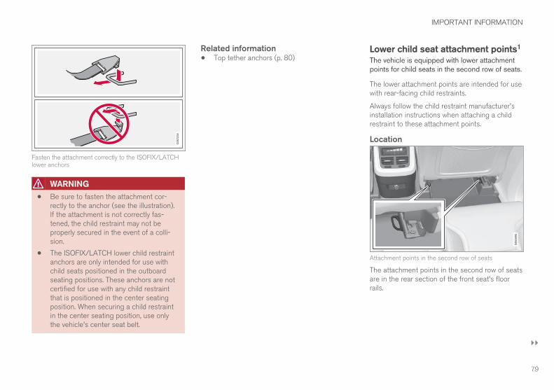
IMPORTANT INFORMATION
}}
79
Fasten the attachment correctly to the ISOFIX/LATCHlower anchors
WARNING
• Be sure to fasten the attachment cor-rectly to the anchor (see the illustration).If the attachment is not correctly fas-tened, the child restraint may not beproperly secured in the event of a colli-sion.
• The ISOFIX/LATCH lower child restraintanchors are only intended for use withchild seats positioned in the outboardseating positions. These anchors are notcertified for use with any child restraintthat is positioned in the center seatingposition. When securing a child restraintin the center seating position, use onlythe vehicle's center seat belt.
Related information• Top tether anchors (p. 80)
Lower child seat attachment points1
The vehicle is equipped with lower attachmentpoints for child seats in the second row of seats.
The lower attachment points are intended for usewith rear-facing child restraints.
Always follow the child restraint manufacturer'sinstallation instructions when attaching a childrestraint to these attachment points.
Location
Attachment points in the second row of seats
The attachment points in the second row of seatsare in the rear section of the front seat's floorrails.

||
IMPORTANT INFORMATION
80
WARNING
A child seat should never be used in the frontpassenger seat of any vehicle with a frontpassenger airbag – not even if the "Passen-ger airbag off" symbol near the rear-view mir-ror is illuminated (on vehicles equipped withOccupant Weight Sensor). If the severity of anaccident were to cause the airbag to inflate,this could lead to serious injury or death to achild seated in this position.
Related information• Child restraints (p. 71)
• ISOFIX/LATCH lower anchors (p. 78)
• Occupant weight sensor (p. 63)
Top tether anchorsYour Volvo is equipped with child restraint toptether anchorages, located on the rear side ofthe backrests, for all three seating positions inthe second row of seats.
Child restraint anchorages
Top tether anchors and symbols on the rear side of thesecond row backrests. There is no symbol for the centeranchor position.
Securing a child seat1. Place the child restraint on the rear seat.
2. Route the top tether strap under the headrestraint and attach it to the anchor.
3. Attach lower tether straps to the lower ISO-FIX/LATCH anchors. If the child restraint isnot equipped with lower tether straps, or therestraint is used in the center seating posi-tion, follow instructions for securing a childrestraint using the Automatic LockingRetractor seat belt.
– Firmly tension all straps.
Refer also to the child seat manufacturer'sinstructions for information on securing the childseat.
NOTE
On models equipped with the optional cargocompartment cover, this cover should beremoved before a child seat is attached to thechild restraint anchors.
WARNING
• Always refer to the recommendationsmade by the child restraint manufacturer.
• Volvo recommends that the top tetheranchors be used when installing a for-ward-facing child restraint.
• Never route a top tether strap over thetop of the head restraint. The strap
1 Not available in all markets

IMPORTANT INFORMATION
}}
* Option/accessory. 81
should be routed beneath the headrestraint.
• Child restraint anchorages are designedto withstand only those loads imposed bycorrectly fitted child restraints. Under nocircumstances are they to be used foradult seat belts or harnesses. The ancho-rages are not able to withstand excessiveforces on them in the event of collision iffull harness seat belts or adult seat beltsare installed to them. An adult who uses abelt anchored in a child restraint anchor-age runs a great risk of suffering severeinjuries should a collision occur.
• Do not install rear speakers that requirethe removal of the top tether anchors orinterfere with the proper use of the toptether strap.
Related information• Child safety (p. 69)
• Child restraints (p. 71)
Integrated booster cushion*Volvo's optional integrated booster cushion islocated in the rear seat's center position and isdesigned to raise the child higher so that theshoulder strap crosses over the child's collar-bone, not over the neck.
Integrated booster cushion2
This booster cushion has been speciallydesigned to help safeguard children in the rearseat. It should be stowed (folded down into theseat cushion) when not in use. When using anintegrated booster cushion, the child must besecured with the vehicle's three-point seat belt.
If using a booster cushion does not result inproper positioning of the shoulder strap, then thechild should be placed in a properly secured childrestraint. The shoulder belt must never be placedbehind the child's back or under the arm.
Use only with children who weigh between 33and 80 pounds (15 – 36 kg) and whose height isbetween 38 and 54 inch (97 – 137 cm).
In Canada: 18 kg (40 lbs) is the minimumweight requirement for a child using boosterseats according to the Canadian regulationCMVSS 213.4
Correct seating position: the shoulder belt is across thecollarbone
2 Canada only: This cushion may be referred to as a built-in booster cushion.

||
IMPORTANT INFORMATION
* Option/accessory.82
WARNING
DEATH or SERIOUS INJURY canoccur
• Follow all instructions on thischild restraint and in the vehicle’sowner’s manual.
• Make sure the booster cushion issecurely locked before the childis seated.
• Use only with children who weighbetween 33 and 80 pounds (15 – 36 kg)and whose height is between 38 and 54inch (97 – 137 cm). In Canada: 18 kg(40 lbs) is the minimum weight require-ment for a child using booster seatsaccording to the Canadian regulationCMVSS 213.4
• Use only the vehicle’s lap and shoulderbelt system when restraining the child inthis booster seat.
• In the event of a collision while the inte-grated booster cushion was occupied, theentire booster cushion and seat belt mustbe replaced. The booster cushion shouldalso be replaced if it is badly worn ordamaged in any way. This work should beperformed by a trained and qualifiedVolvo service technician only.
Before driving, check that:
• The integrated booster cushion has beencorrectly raised and locked in position.
• That the seat belt is properly positioned andis taut.
• The shoulder section of the seat belt isacross the child's collarbone, not over theneck.
• The lap section of the seat belt is across thechild's hips and not the abdomen.
• The head restraint is set to same height asthe child’s head so that, if possible, the entireback of the child's head is covered.
Related information• Seat belts (p. 54)
• Child safety (p. 69)
• Raising the integrated booster cushion*(p. 82)
• Stowing the integrated booster cushion*(p. 84)
Raising the integrated boostercushion*The integrated booster cushion in the secondrow of seat's center position must be correctlyraised before use.
Pull the handle forward and upward torelease the booster cushion.

IMPORTANT INFORMATION
* Option/accessory. 83
Press the booster cushion rearward to lock itin position.
WARNING
DEATH or SERIOUS INJURY canoccur
• Follow all instructions on thischild restraint and in the vehicle’sowner’s manual.
• Make sure the booster cushion issecurely locked before the childis seated.
• Use only with children who weighbetween 33 and 80 pounds (15 – 36 kg)and whose height is between 38 and 54inch (97 – 137 cm). In Canada: 18 kg(40 lbs) is the minimum weight require-ment for a child using booster seatsaccording to the Canadian regulationCMVSS 213.4
• Use only the vehicle’s lap and shoulderbelt system when restraining the child inthis booster seat.
• In the event of a collision while the inte-grated booster cushion was occupied, theentire booster cushion and seat belt mustbe replaced. The booster cushion shouldalso be replaced if it is badly worn ordamaged in any way. This work should beperformed by a trained and qualifiedVolvo service technician only.
Related information• Integrated booster cushion* (p. 81)
• Stowing the integrated booster cushion*(p. 84)

IMPORTANT INFORMATION
* Option/accessory.84
Stowing the integrated boostercushion*The integrated booster cushion in the secondrow of seat's center position should be stowed(folded down) when not in use.
Pull the handle forward to release thebooster cushion.
Press down on the center of the boostercushion to return it to the stowed position.
NOTE
The booster cushion must be in the stowedposition before the rear seat backrests arefolded down.
CAUTION
Be sure there are no loose objects under thebooster cushion before it is stowed.
WARNING
DEATH or SERIOUS INJURY canoccur
• Follow all instructions on thischild restraint and in the vehicle’sowner’s manual.
• Make sure the booster cushion issecurely locked before the childis seated.
• Use only with children who weighbetween 33 and 80 pounds (15 – 36 kg)and whose height is between 38 and 54inch (97 – 137 cm). In Canada: 18 kg(40 lbs) is the minimum weight require-ment for a child using booster seatsaccording to the Canadian regulationCMVSS 213.4
• Use only the vehicle’s lap and shoulderbelt system when restraining the child inthis booster seat.
• In the event of a collision while the inte-grated booster cushion was occupied, theentire booster cushion and seat belt mustbe replaced. The booster cushion shouldalso be replaced if it is badly worn ordamaged in any way. This work should beperformed by a trained and qualifiedVolvo service technician only.

IMPORTANT INFORMATION
* Option/accessory. 85
Related information• Integrated booster cushion* (p. 81)
• Raising the integrated booster cushion*(p. 82)


PRACTICAL INFORMATION

PRACTICAL INFORMATION
* Option/accessory.88
Passenger compartment storagespacesThe following is an overview of the passengercompartment and its storage spaces.
Front seats
Storage spaces in the door panel, near the steeringwheel, the glove compartment and the sun visors
Storage spaces, cup holders and 12-volt socket/USBsocket in the tunnel console
Second row of seats
Storage compartments in the door panels, cup holdersin the center seat's backrest, storage pockets on therear side of the front seat backrest, and 12-volt socketon the rear side of the tunnel console
Third row of seats*
Storage space and cup holder in the side panel and thestorage space between the seats
WARNING
Always stow loose items such as cell phones,cameras, remote controls, etc. in the glovecompartment or other storage spaces to helpkeep them from becoming projectiles in theevent of sudden braking, etc.
Related information• Tunnel console (p. 90)
• Using the glove compartment (p. 90)
• Electrical sockets (p. 131)
• Sun visors (p. 91)

PRACTICAL INFORMATION
89
Engine compartment overviewThe engine compartment overview shows somemaintenance points.
The layout of the engine compartment may differ slightlyfrom model to model
Coolant expansion tank
Brake fluid reservoir
Washer fluid reservoir
Relay/fuse box
Air cleaner
Engine oil filler cap
WARNING
• The cooling fan (located at the front ofthe engine compartment, behind the radi-ator) may start or continue to operate (forup to 6 minutes) after the engine hasbeen switched off.
• Engine cleaning should only be done by aworkshop. If engine cleaning agents areused when the engine has been running,there may a fire risk.
• Before performing any operations in theengine compartment, the ignition shouldalways be completely switched off (inmode 0) and there should be no remotekeys in the passenger compartment. Thegear selector should be in the P (park)position. If the engine has been running,wait until it has cooled before touchingany components in the engine compart-ment.
• The distributor ignition system operatesat very high voltages. Special safety pre-cautions must be followed to preventinjury. Always turn the ignition off whenreplacing distributor ignition componentse.g. plugs, coil, etc.
• Do not touch any part of the distributorignition system while the engine is run-ning. This may result in unintended move-ments and body injury.
Related information• Opening and closing the hood (p. 143)
• Refilling the windshield washer fluid reservoir(p. 142)

PRACTICAL INFORMATION
* Option/accessory.90
Using the glove compartmentThe glove compartment provides storage spacefor small items.
The glove compartment and opening button on the cen-ter console
The owner's manual and maps can be kept here.There are also holders for pens on the inside ofthe glove compartment door.
Opening the glove compartment– Press the glove compartment button on the
center console.
> The glove compartment door will open.
Locking/unlocking the glovecompartmentThe glove compartment and tailgate can belocked when e.g., the vehicle is in a workshop forservice, etc. See also the article "Private locking"for additional information.
Using the glove compartment as acooler*The glove compartment can be used to cooldrinks or food and the cooling feature functionswhen the climate system is active (i.e., when theignition is in mode II or when the engine is run-ning).
Cooling activated
Cooling deactivated
– Activate/deactivate cooling by moving thecontrol as far as possible toward the passen-ger compartment/glove compartment.
Related information• Passenger compartment storage spaces
(p. 88)
Tunnel consoleThe tunnel console, located between the frontseats, contains a 12-volt electrical socket, cupholders and storage spaces, etc.
Storage space*. Press the handle to openthe cover.
Storage space with cup holders for the driverand passenger and a 12-volt socket
Storage space and USB socket under thearmrest
Climate control panel for the rear seats* orstorage space

PRACTICAL INFORMATION
}}
91
NOTE
One of the alarm sensors, which is sensitiveto metallic objects, is located under the tunnelconsole cup holders. Avoid leaving coins,keys, etc., in the cup holders because theymay inadvertently trigger the alarm.
Related information• Passenger compartment storage spaces
(p. 88)
• Electrical sockets (p. 131)
Sun visorsThere are vanity mirrors with card holders on theupper sides of the sun visors.
Lighted vanity mirror and card holder
The vanity mirror lighting comes on when the mir-ror is opened.
The vanity mirror's frame has a holder for e.g., acard or ticket.
Related information• Passenger compartment storage spaces
(p. 88)
LoadingThe load carrying capacity of your vehicle isdetermined by factors such as the number ofpassengers, the amount of cargo, the weight ofany accessories that may be installed, etc.
Loading recommendations• Load objects in the cargo compartment
against the backrest whenever possible.
• If the backrests of the second row seats arefolded down, they should not be in contactwith the front seat backrests. This couldimpede the function of the WhiplashProtection System (WHIPS).
• Unstable loads can be secured to the loadanchoring eyelets with straps or web lash-ings to help keep them from shifting.
• Stop the engine and apply the parking brakewhen loading or unloading long objects. Thegear selector can be knocked out of positionby long loads, which could set the vehicle inmotion.

||
PRACTICAL INFORMATION
* Option/accessory.92
WARNING
• Stop the engine, put the gear selector inP, and apply the parking brake whenloading or unloading long objects.
• The vehicle's driving characteristics maychange depending on the weight and dis-tribution of the load.
• A 44-pound (20 kg) object produces aforce of 2,200 pounds (1,000 kg) in ahead-on collision at 30 mph (50 km/h).
• The cargo compartment and rear seatshould not be loaded to a level higherthan 2 in. (5 cm) below the upper edge ofthe rear side windows. Objects placedhigher than this level could impede thefunction of the Inflatable Curtain.
WARNING
• Cover sharp edges on long loads to helpprevent injury to occupants. Secure theload to help prevent shifting during sud-den stops.
• Always secure large and heavy objectswith a seat belt or cargo retaining straps.
• Always secure the load to help prevent itfrom moving in the event of sudden stops.
• Switch off the engine, apply the parkingbrake and put the gear selector in Pwhen loading and unloading the vehicle.
Raising/lowering the rear-end of thevehicle*Using the buttons on the read edge of the cargocompartment, the rear-end of the vehicle (thelevel of the cargo compartment floor) can beraised or lowered for easier loading or to makeattaching a trailer1 simpler.
Level control buttons on the rear edge of the cargocompartment
The level control consists of two buttons: one toraise and one to lower the rear-end of the vehi-cle.
Press and hold the respective buttons until thedesired level has been reached.
NOTE
The level cannot be adjusted if a door or thehood are open (this does not apply to the tail-gate).
WARNING
Be sure that the entire area under the vehicleis completely unobstructed before loweringthe level.
1 An accessory trailer hitch can be purchased from a Volvo retailer.

PRACTICAL INFORMATION
}}
* Option/accessory. 93
Extra loading spaceThe vehicle has flexible cargo capacity thatmakes it possible to load and secure largeobjects and loading capacity can be increasedwhen needed.
By folding down the backrests in the second andthird rows* of seats, the cargo capacity of thevehicle increases considerably. To make loadingeasier, the rear section of the vehicle can beraised and lowered using the pneumatic suspen-sion*. Use the load anchoring eyelets or the gro-cery bag holder to secure objects and the cargocompartment cover to help conceal the load.
The spare tire, jack and tools can be found underthe cargo compartment's floor.
WARNING
• Boxes, suitcases, etc. wedged behind thefront seats could impede the function ofthe Whiplash Protection System.
• If the rear seat backrests are foldeddown, cargo must be secured to preventit from sliding forward against the frontseat backrests in the event of a collisionfrom the rear. This could interfere withthe action of the Whiplash ProtectionSystem.
WARNING
• Cover sharp edges on long loads to helpprevent injury to occupants. Secure theload to help prevent shifting during sud-den stops.
• Always secure large and heavy objectswith a seat belt or cargo retaining straps.
• Always secure the load to help prevent itfrom moving in the event of sudden stops.
• Switch off the engine, apply the parkingbrake and put the gear selector in Pwhen loading and unloading the vehicle.
Roof loadsLoad carriers are available as Volvo accessories.Observe the following points when in use:
• To avoid damaging your vehicle and toachieve maximum safety when driving, werecommend using the load carriers that Volvohas developed especially for your vehicle.
• Volvo-approved removable roof racks aredesigned to carry the maximum allowableroof load for this vehicle (see the article"Weights" for specific information).
• Never exceed the rack manufacturer's weighlimits.
• Avoid single-point loads. Distribute loadsevenly.
• Place heavier cargo at the bottom of theload.
• Secure the cargo correctly with appropriatetie-down equipment.
• Check periodically that the load carriers andload are properly secured.
• Remember that the vehicle's center of gravityand handling change when you carry a loadon the roof.
• The vehicle's wind resistance and fuel con-sumption will increase with the size of theload.
• Drive smoothly. Avoid rapid starts, fast cor-nering and hard braking.
CAUTION
The optional panoramic roof should not beopened while load carriers are installed onthe vehicle.
See the article "Weights" for information aboutthe maximum permissible load that can be trans-ported on the roof.
Related information• Weights (p. 167)
• Cargo net (p. 95)
• Cargo compartment cover* (p. 98)
• Steel cargo grid* (p. 96)

PRACTICAL INFORMATION
* Option/accessory.94
• Load anchoring eyelets (p. 98)
• Whiplash protection system (p. 53)
Grocery bag holderThe grocery bag holders (hooks) and elasticstrap help keep shopping bags in place.
Under the cargo compartment floor2
There are two grocery bag holders and an elasticstrap3 in the hatch that is part of the cargo com-partment floor. The strap can be attached in fourpositions.
Open the hatch to access the grocery bag hold-ers and attach the elastic strap. Grocery bagswith handles can also be hung on the hooks.
On the sides
There are also two fold-out holders in the sidepanels, one on each side.
CAUTION
The grocery bag holders (hooks) are onlyintended to hold weights less than approx.11 lbs (5 kg).
Related information• Cargo net (p. 95)
• Steel cargo grid* (p. 96)
• Cargo compartment cover* (p. 98)
2 5-seat models only.3 Can be replaced by ordering a new one from a Volvo retailer.

PRACTICAL INFORMATION
}}
95
Cargo netThe cargo net helps protect passengers fromobjects in the cargo compartment in the event ofa sudden stop or hard braking.
The cargo net is attached at four points.
Cargo net
The cargo net can be mounted in two positions:
• Rear mounting: behind the second row seats'backrests.
• Front mounting: behind the front seats' back-rests.
WARNING
• Objects in the cargo compartment shouldalways be securely anchored.
• All of the net's attachment points must besecurely in place when the net is used.
• A damaged net must never be used.
Installing the net
NOTE
Front mounting is done most easily throughone of the rear doors.
1. Fold out the cargo net and be sure the twosections of the upper rod are locked in thefolded-out position.
2. Insert one of the net's upper hooks into thefront or rear ceiling mounting point with thenet's lower straps' locks facing you.
3. Insert the other upper hook into the ceilingmounting point on the opposite side. It isspring-loaded to make mounting easier.
Press each of the hooks as far forward intothe respective mounting points as possible.
Rear mounting
4. Rear mounting: with the upper hooksinserted into the rear ceiling mounting points,hook the lower straps through the loadanchoring eyelets on the floor of the cargocompartment as show in the illustration.

||
PRACTICAL INFORMATION
* Option/accessory.96
Front mounting
Front mounting: with the upper hooksinserted into the front ceiling mountingpoints, hook the lower straps through theeyelets on the front seat floor rails as shownin the illustration. Attaching the net is easierif the front seat backrests are upright and theseats are moved slightly forward.
Adjust the front seats so that they only touchthe net but do not apply pressure to it.
5. Pull the lower straps taut.
CAUTION
When moving the front seats with the cargonet installed, only move the seat(s)/back-rest(s) rearward until they touch the net.
Excessive pressure from the front seatsagainst the cargo net could damage the netand/or its brackets.
Removing and storing1. Reduce tension on the net by pressing the
button on the lower straps' respective locksand allow some slack on both sides.
2. Press in the catches and release both of thestraps' hooks.
3. Remove the upper hooks from the ceilingmounting points.
4. Press the red button on the upper rod toallow it to fold.
5. Fold and roll up the net.
Store the net under the cargo compartment floor.
Related information• Cargo compartment cover* (p. 98)
• Load anchoring eyelets (p. 98)
• Steel cargo grid* (p. 96)
• Loading (p. 91)
Steel cargo grid*Your vehicle can be equipped with a steel gridthat helps prevent objects in the cargo compart-ment from moving forward into the passengerarea.
The steel grid is made up of the grid itself andtwo separate mounting brackets.
Each of the brackets has a screw cover and thereare two plastic sleeves for the grid.
WARNING
• No one should ever be allowed to remainin the cargo compartment when the vehi-cle is moving.
• The steel grid may only be used in therear position described in this article. Theceiling attachment points above the frontseats are not intended to anchor thesteel grid.
• The third row of seats (7-seat models*only): these seats must be folded downwhen the steel grid is mounted in thevehicle.
• After being mounted, be sure that thesteel grid is securely anchored in place.
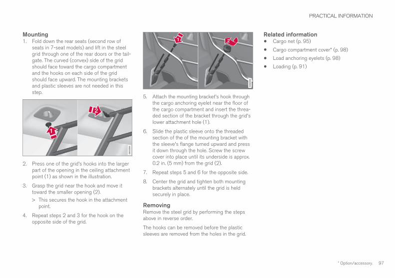
PRACTICAL INFORMATION
* Option/accessory. 97
Mounting1. Fold down the rear seats (second row of
seats in 7-seat models) and lift in the steelgrid through one of the rear doors or the tail-gate. The curved (convex) side of the gridshould face toward the cargo compartmentand the hooks on each side of the gridshould face upward. The mounting bracketsand plastic sleeves are not needed in thisstep.
2. Press one of the grid's hooks into the largerpart of the opening in the ceiling attachmentpoint (1) as shown in the illustration.
3. Grasp the grid near the hook and move ittoward the smaller opening (2).
> This secures the hook in the attachmentpoint.
4. Repeat steps 2 and 3 for the hook on theopposite side of the grid.
5. Attach the mounting bracket's hook throughthe cargo anchoring eyelet near the floor ofthe cargo compartment and insert the threa-ded section of the bracket through the grid'slower attachment hole (1).
6. Slide the plastic sleeve onto the threadedsection of the of the mounting bracket withthe sleeve's flange turned upward and pressit down through the hole. Screw the screwcover into place until its underside is approx.0.2 in. (5 mm) from the grid (2).
7. Repeat steps 5 and 6 for the opposite side.
8. Center the grid and tighten both mountingbrackets alternately until the grid is heldsecurely in place.
RemovingRemove the steel grid by performing the stepsabove in reverse order.
The hooks can be removed before the plasticsleeves are removed from the holes in the grid.
Related information• Cargo net (p. 95)
• Cargo compartment cover* (p. 98)
• Load anchoring eyelets (p. 98)
• Loading (p. 91)

PRACTICAL INFORMATION
* Option/accessory.98
Load anchoring eyeletsThe eyelets in the cargo compartment can befolded out to secure objects with straps, a net,etc.
Load anchoring eyelets
WARNING
• Cover sharp edges on long loads to helpprevent injury to occupants. Secure theload to help prevent shifting during sud-den stops.
• Always secure large and heavy objectswith a seat belt or cargo retaining straps.
• Always secure the load to help prevent itfrom moving in the event of sudden stops.
• Switch off the engine, apply the parkingbrake and put the gear selector in Pwhen loading and unloading the vehicle.
Related information• Loading (p. 91)
• Grocery bag holder (p. 94)
• Cargo net (p. 95)
• Steel cargo grid* (p. 96)
• Cargo compartment cover* (p. 98)
Cargo compartment cover*The cover can be used to conceal objects in thecargo compartment.
Installing the cover
With the cover retracted, press the end pieceon one side of the cargo compartment coverinto the retaining bracket in the side panel ofthe cargo compartment.
Do the same on the opposite side.
Press both sides of the cover, one at a time,until they click into place.
> The red mark will no longer be visible.Check that both ends of the cover aresecurely locked in place.
Using the coverThe cover can be used in two positions: fullyopen to completely cover the cargo compartment

PRACTICAL INFORMATION
}}
99
or partially retracted to make it easier to reachfarther into the cargo compartment.
Fully open7-seat models
1.
Third row seats: hang the seat belt latches inthe hooks provided in the side panels.
Grasp the handle and pull out the coverabove the side panels in the cargo compart-ment as far as possible.
With the cover completely open, press theattaching pins on the rear corners of thecover into the grooves in the side panels andrelease the cover slightly while pressing thehandle lightly downward.
> The cover is now fixed in the fully openposition.
5-seat models
Grasp the handle and pull out the coverabove the side panels in the cargo compart-ment as far as possible.
With the cover completely open, press theattaching pins on the rear corners of thecover into the grooves in the side panels andrelease the cover slightly while pressing thehandle lightly downward.
> The cover will remain in the fully openposition.

||
PRACTICAL INFORMATION
100
Loading (partially retracted) position
With the cover retracted, grasp its handleand pull it so that it is above the cargo com-partment's side panels until it is fully open.Press the attaching pins on the rear cornersof the cover into the grooves in the side pan-els. If the cover is already fully open see thenext step.
With the cover completely pulled out, press itupward lightly and allow it to retract slowly.
> Allow the cover to retract until it stops inthe loading position.
If you are holding something in one of yourhands:
From the fully open position, push the cover'shandle slightly upward with e.g., your elbow.
> The cover will close until it reaches theloading position.
To fully open the cover from the loading position:
1. Grasp the handle and pull out the cover tothe fully open position.
2. Let the cover retract slightly and press thehandle slightly downward.
> The cover will be secured n the fully openposition.
Avoid placing any objects on the cover when it isopen.
WARNING
7-seat models: remove the cargo compart-ment cover completely from the vehicle if oneor both of the third row seats will be occupied.
Retracting the coverFrom the fully open position:
– Lift the cover's handle and pull it rearwardslightly to release the attaching pins fromtheir grooves. Allow the cover to retract.
From the partially retracted position:
– Grasp the handle and lift it slightly to releasethe attaching pins from their grooves. Pullthe cover to the fully open position.
> Allow the cover to retract completely.
Removing the cover1. With the cover retracted, press the button on
one of the cover's ends and lift out that end.
For 7-seat models: Release the seat beltlatches from the hooks in the side panels.For 5-seat models, see the following step.
2. Carefully lift the cover up/out.
> The other end will release automatically.Lift the cover out of the cargo compart-ment.

PRACTICAL INFORMATION
}}
101
Automatically arming/disarming thealarmAutomatically arming the alarm helps preventinadvertently leaving the vehicle without alarmprotection.
If the vehicle has been unlocked with the remotekey (and the alarm has been disarmed) but nodoor or the tailgate has been opened within2 minutes, the vehicle will automatically relockand the alarm will re-arm.
In certain markets, the alarm will be re-armedautomatically after a slight delay after the driver'sdoor has been opened and closed without beinglocked.
Octane ratingVolvo requires premium fuel (91 octane orabove) for best performance.
Minimum octane
Sample fuel pump octane label
TOP TIER Detergent GasolineVolvo endorses the use of “TOP TIER DetergentGasoline” where available to help maintain engineperformance and reliability. TOP TIER DetergentGasoline meets a new standard jointly estab-lished by leading automotive manufactures tomeet the needs of today’s advanced engines.Qualifying gasoline retailers (stations) will, inmost cases, identify their gasoline as having metthe “TOP TIER Detergent Gasoline” standards.
NOTE
Information about TOP TIER Detergent Gaso-line is available at www.toptiergas.com.
NOTE
When switching to higher octane fuel orchanging gasoline brands, it may be neces-sary to fill the tank more than once before adifference in engine operation is noticeable.
Fuel FormulationsDo not use gasoline that contains lead as aknock inhibitor, and do not use lead additives.Besides damaging the exhaust emission controlsystems on your vehicle, lead has been stronglylinked to certain forms of cancer.
Many fuels contain benzene as a solvent.Unburned benzene has been strongly linked tocertain forms of cancer. If you live in an areawhere you must fill your own gas tank, take pre-cautions. These may include:
• standing upwind away from the filler nozzlewhile refueling.
• refueling only at gas stations with vaporrecovery systems that fully seal the mouth ofthe filler neck during refueling.
• wearing neoprene gloves while handling afuel filler nozzle.

||
PRACTICAL INFORMATION
102
Use of AdditivesWith the exception of gas line antifreeze duringwinter months, do not add solvents, thickeners, orother store-bought additives to your vehicle'sfuel, cooling, or lubricating systems. Overuse maydamage your engine, and some of these additivescontain organically volatile chemicals. Do notneedlessly expose yourself to these chemicals.
WARNING
Never carry a cell phone that is switched onwhile refueling your vehicle. If the phone rings,this may cause a spark that could ignite gaso-line fumes, resulting in fire and injury.
WARNING
Carbon monoxide is a poisonous, colorless,and odorless gas. It is present in all exhaustgases. If you ever smell exhaust fumes insidethe vehicle, make sure the passenger com-partment is ventilated, and immediately returnthe vehicle to a trained and qualified Volvoservice technician for correction.
Opening/closing the fuel filler doorThe fuel tank has a filling system that does nothave a cover.
Opening/closing the fuel filler doorThe vehicle must be unlocked before the fuelfiller door can be opened.
An arrow next to the fuel pumpsymbol in the instrument panelindicates the side of the vehiclewhere the fuel filler door islocated.
1. Open the fuel filler door by pressing lightlyon its rear edge.
2. After refueling, close the fuel filler door bypressing lightly.
Refueling from a service station pump
To refuel:
1. Open the fuel filler door. Do not refuel withthe engine running4
2. Insert the pump's nozzle into the fuel fillerpipe's opening as far as possible (see theillustration).
3. Avoid overfilling the fuel tank. Do not pressthe handle on the filler nozzle after it hasstopped pumping. Too much fuel in the tankin hot weather conditions can cause the fuelto overflow. Overfilling could also cause dam-age to the emission control systems.
4 If the engine is running when the vehicle is refueled, the Check Engine Light (malfunction indicator lamp) may indicate a fault. However, your vehicle's performance will not be affected.

PRACTICAL INFORMATION
}}
103
CAUTION
Avoid spilling gasoline during refueling. Inaddition to causing damage to the environ-ment, gasolines containing alcohol can causedamage to painted surfaces, which may notbe covered under the New Vehicle LimitedWarranty.
Related information• Octane rating (p. 101)
TiresYour vehicle is equipped with tires according tothe vehicle's tire information placard on the B-pillar (the structural member at the side of thevehicle, at the rear of the driver's door opening).
CAUTION
Some Volvo models are equipped with anUltra High Performance tire and wheel com-bination designed to provide maximum drypavement performance with consideration forhydroplaning resistance. They may be moresusceptible to road hazard damage and,depending on driving conditions, may achievea tread life of less than 20,000 miles (30,000km). Even if this vehicle is equipped with Vol-vo’s advanced AWD or stability system, thesetires are not designed for winter driving, andshould be replaced with winter tires whenweather conditions dictate.
The tires have good road holding characteristicsand offer good handling on dry and wet surfaces.It should be noted however that the tires havebeen developed to give these features on snow/ice-free surfaces.
Most models are equipped with "all-season" tires,which provide a somewhat higher degree of roadholding on slippery surfaces than tires withoutthe "all-season" rating. However, for optimum
road holding on icy or snow-covered roads, werecommend suitable winter tires on all fourwheels.
When replacing tires, be sure that the new tiresare the same size designation, type (radial) andpreferably from the same manufacturer, on allfour wheels. Otherwise there is a risk of alteringthe car's roadholding and handling characteris-tics.
Recommended tiresYour vehicle is factory-equipped with Volvo origi-nal tires that are marked VOL5 on the sidewall.These tires have been carefully adapted to yourvehicle. When replacing tires, it is important thatthe new ones also have the VOL designation inorder to help maintain the vehicle's driving andhandling characteristics.
5 There may be certain exceptions depending on the tire's dimensions.

||
PRACTICAL INFORMATION
104
New tires
Remember that tires are perishable goods. As of2000, the manufacturing week and year (Depart-ment of Transportation (DOT) stamp) will be indi-cated with 4 digits (e.g., 0715 means that the tireillustrated was manufactured during week 7 of2015).
Tire ageTires degrade over time, even when they are notbeing used. It is recommended that tires gener-ally be replaced after 6 years of normal service.Heat caused by hot climates, frequent high load-ing conditions or Ultra Violet (U.V.) exposure canaccelerate the aging process. The temporaryspare6 should also be replaced at 6-year inter-vals, even if it has never been used. A tire's agecan be determined by the DOT stamp on thesidewall (see the illustration). A tire with e.g., visi-
ble cracks or discoloration should be replacedimmediately.
Tire economy• Maintain correct tire pressure.
• Avoid fast starts, hard braking and tirescreeching.
• Tire wear increases with speed.
• Correct front wheel alignment is very impor-tant.
• Unbalanced wheels impair tire economy anddriving comfort.
• Tires must maintain the same direction ofrotation throughout their lifetime.
• When replacing tires, the tires with the mosttread should be mounted on the rear wheelsto reduce the chance of oversteer duringhard braking.
• Hitting curbs or potholes can damage thetires and/or wheels permanently.
Tire rotationYour vehicle has no required tire rotation. Tirewear is affected by a number of factors such astire inflation, ambient temperature, driving style,etc.
NOTE
• If the tires are rotated, they should onlybe moved from front to rear or vice versa.They should never be rotated left toright/right to left.
• Ideally, tire rotation should be done thefirst time after approximately 3,000 miles(5,000 km) and thereafter at 6,000-mile(10,000-km) intervals. Some customersfind that tire rotation may help to getextra mileage from tire life.
• Tire rotation should only be performed iffront/rear tire wear is fairly even andtread height is above 1/16" (1.6 mm).
Storing wheels and tiresWhen storing complete wheels (tires mounted onrims), they should be suspended off the floor orplaced on their sides on the floor.
Tires not mounted on rims should be stored ontheir sides or standing upright, but should not besuspended.
CAUTION
Tires should preferably be stored in a cool,dry, dark place, and should never be stored inclose proximity to solvents, gasoline, oils, etc.
6 Not available in all models.

PRACTICAL INFORMATION
}}
105
WARNING
• The wheel and tire sizes for your Volvoare specified to meet stringent stabilityand handling requirements. Unapprovedwheel/tire size combinations can nega-tively affect your vehicle's stability andhandling.
• Any damage caused by installation ofunapproved wheel/tire size combinationswill not be covered by your new vehiclewarranty. Volvo assumes no responsibilityfor death, injury, or expenses that mayresult from such installations.
Related information• Checking tire inflation pressure (p. 111)
• Tread wear indicator (p. 109)
Tire sidewall designationsThe following information can be found on atire's sidewall.
Federal law mandates that tire manufacturersplace standardized information on the sidewall ofall tires (see the illustration).
The vehicle has been certified with certain combi-nations of wheels and tires.
The following information is listed on the tiresidewall:
The tire designation:
NOTE
Please be aware that the following tire desig-nation is an example only and that this par-ticular tire may not be available on your vehi-cle.
1. 215: the width of the tire (in millimeters)from sidewall edge to sidewall edge. Thelarger the number, the wider the tire.
2. 65: The ratio of the tire's height to its widthin percent.
3. R: Radial tire (the designation RF and the
symbol indicate that the vehicle isequipped with optional self-supporting runflat tires7.
4. 15: The diameter of the wheel rim (ininches).
5. 95: The tire's load index. In this example, aload index of 95 equals a maximum load of1521 lbs (690 kg).
6. H: The tire's speed rating, or the maximumspeed at which the tire is designed to bedriven for extended periods of time, carryinga permissible load for the vehicle, and withcorrect inflation pressure. For example, Hindicates a speed rating of 130 mph(210 km/h).
7 Self-supporting run flat tires may not be available on all models

||
PRACTICAL INFORMATION
106
NOTE
The tire's load index and speed rating maynot appear on the sidewall because they arenot required by law.
7. M+S or M/S = Mud and Snow, AT = All Ter-rain, AS = All Season
8. U.S. DOT Tire Identification Number(TIN): This begins with the letters "DOT" andindicates that the tire meets all federalstandards. The next two numbers or lettersare the plant code where it was manufac-tured, the next two are the tire size code andthe last four numbers represent the weekand year the tire was built. For example,1510 means that the tire was manufacturedduring week 15 of 2010. The numbers inbetween are marketing codes used at themanufacturer's discretion. This informationhelps a tire manufacturer identify a tire forsafety recall purposes.
9. Tire Ply Composition and Material Used:Indicates the number of plies indicates or thenumber of layers of rubber-coated fabric inthe tire tread and sidewall. Tire manufactur-ers also must indicate the ply materials in thetire and the sidewall, which include steel,nylon, polyester, and others.
10. Maximum Load: Indicates the maximumload in pounds and kilograms that can becarried by the tire. Refer to the vehicle's tire
information placard located on the B-Pillarfor the correct tire pressure for your vehicle.
11. Treadwear, Traction, and Temperaturegrades.
12. Maximum permissible inflation pressure:the greatest amount of air pressure thatshould ever be put in the tire. This limit is setby the tire manufacturer.
Speed SymbolA tire's Speed Symbol (SS) indicates the maxi-mum speed for which the tire has been certifiedand should be at least equivalent to the vehicle'stop speed.
Winter tires, with our without studs, are excep-tions and may use a lower SS. When winter tiresare installed, the vehicle may not be driven fasterthan the tires' SS.
The vehicle's speed should always be determinedby the posted speed limit and traffic and roadconditions, not the tire's SS.
The following table indicates the maximum per-missible speed for each SS.
Speed Symbol
M 81 mph (130 km/h)
Q 100 mph (160 km/h)
T 118 mph (190 km/h)
Speed Symbol
H 130 mph (210 km/h)
V 149 mph (240 km/h)
W 168 mph (270 km/h)
Y 186 mph (300 km/h)
WARNING
• The wheel and tire sizes for your Volvoare specified to meet stringent stabilityand handling requirements. Unapprovedwheel/tire size combinations can nega-tively affect your vehicle's stability andhandling.
• Any damage caused by installation ofunapproved wheel/tire size combinationswill not be covered by your new vehiclewarranty. Volvo assumes no responsibilityfor death, injury, or expenses that mayresult from such installations.

PRACTICAL INFORMATION
}}
107
Wheel (rim) designationsWheel and rim dimensions are shown in the fol-lowing table.
The vehicle has been certified with certain combi-nations of wheels and tires.
The following table shows an example of wheeldimensions: 8Jx18x42.5. This particular wheelmay not be available on your vehicle.
8 Wheel width in inches
J Rim flange profile
18 Wheel diameter in inches
42.5 Offset in mm (distance from the centerof the wheel to the wheel's contact sur-face on the hub)
Related information• Tire sidewall designations (p. 105)
Tire terminologyThe following is a glossary of tire-related terms.
The tire suppliers may have additional markings,notes or warnings such as standard load, radialtubeless, etc.
• Tire information placard: A placard show-ing the OE (Original Equipment) tire sizes,recommended inflation pressure, and themaximum weight the vehicle can carry.
• Tire Identification Number (TIN): A numberon the sidewall of each tire providing infor-mation about the tire brand and manufactur-ing plant, tire size and date of manufacturer.
• Inflation pressure: A measure of theamount of air in a tire.
• Standard load: A class of P-metric or Metrictires designed to carry a maximum load at35 psi [37 psi (2.5 bar) for Metric tires].Increasing the inflation pressure beyond thispressure will not increase the tires load car-rying capability.
• Extra load: A class of P-metric or Metrictires designed to carry a heavier maximumload at 41 psi [43 psi (2.9 bar) for Metrictires]. Increasing the inflation pressurebeyond this pressure will not increase thetire's load carrying capability.
• kPa: Kilopascal, a metric unit of air pressure.
• PSI: Pounds per square inch, a standard unitof air pressure.
• B-pillar: The structural member at the sideof the vehicle behind the front door.
• Bead area of the tire: Area of the tire nextto the rim.
• Sidewall of the tire: Area between the beadarea and the tread.
• Tread area of the tire: Area of the perime-ter of the tire that contacts the road whenmounted on the vehicle.
• Rim: The metal support (wheel) for a tire or atire and tube assembly upon which the tirebeads are seated.
• Maximum load rating: A figure indicatingthe maximum load in pounds and kilogramsthat can be carried by the tire. This rating isestablished by the tire manufacturer.
• Maximum permissible inflation pressure:The greatest amount of air pressure thatshould ever be put in the tire. This limit is setby the tire manufacturer.
• Recommended tire inflation pressure:Inflation pressure, established by Volvo,which is based on the type of tires that aremounted on a vehicle at the factory. Thisinformation can be found on the tire inflationplacard(s) located on the driver's side B-pillarand in the tire inflation table in this chapter.
• Cold tires: The tires are considered to becold when they have the same temperatureas the surrounding (ambient) air. This tem-

PRACTICAL INFORMATION
108
perature is normally reached after the vehiclehas been parked for at least 3 hours.
Tire direction of rotationIncorrectly mounted tires impair the car's brakingproperties and ability to force aside rain, snowand slush.
The arrows shows the direction of rotation of the tire
• The tires with the most tread should alwaysbe on the rear axle (to help reduce the risk ofskidding).
• When switching between summer and wintertires, mark the tires to indicate where theywere mounted on the car, e.g., LF = left front,RR = right rear
• Tires with tread designed to roll in only onedirection are marked with an arrow on thesidewall.
• Contact a trained and qualified Volvo servicetechnician if you are unsure about the treaddepth.
Related information• Tires (p. 103)

PRACTICAL INFORMATION
}}
109
Tread wear indicatorThe tires have wear indicator strips runningacross or parallel to the tread.
The letters TWI are printed on the side of the tire.When approximately 1/16" (1.6 mm) is left onthe tread, these strips become visible and indi-cate that the tire should be replaced. Tires withless than 1/16" (1.6 mm) tread offer very poortraction.
When replacing worn tires, it is recommendedthat the tire be identical in type (radial) and sizeas the one being replaced. Using a tire of thesame make (manufacturer) will help preventalteration of the driving characteristics of thevehicle.
Related information• Tire direction of rotation (p. 108)
• Checking tire inflation pressure (p. 111)
Loading specificationsProperly loading your vehicle will provide maxi-mum return of vehicle design performance.
Weight designations
Before loading your vehicle, familiarize yourselfwith the following terms for determining yourvehicle's weight ratings, with or without a trailer,from the vehicle's Federal/Canadian Motor Vehi-cle Safety Standards (FMVSS/CMVSS) label, andthe vehicle's tire information placard:
Curb weightThe weight of the vehicle including a full tank offuel and all standard equipment. It does notinclude passengers, cargo, or optional equipment.
Capacity weightAll weight added to the curb weight, includingcargo and optional equipment. When towing,trailer hitch tongue load is also part of cargoweight.
Permissible axle weightThe maximum allowable weight that can be car-ried by a single axle (front or rear). These num-bers are shown on the Federal/Canadian MotorVehicle Safety Standards (FMVSS/CMVSS) label.The total load on each axle must never exceed itsmaximum permissible weight.
Gross vehicle weight (GVW)The vehicle's curb weight + cargo + passengers.
Steps for Determining Correct LoadLimit1. Locate the statement "the combined weight
of occupants and cargo should never exceedXXX kg or XXX lbs." on your vehicle's plac-ard.
2. Determine the combined weight of the driverand passengers that will be riding in yourvehicle.
3. Subtract the combined weight of the driverand passengers from XXX kg or XXX lbs.
4. The resulting figure equals the availableamount of cargo and luggage load capacity.For example, if the "XXX" amount equals1400 lbs. and there will be five 150 lb. pas-sengers in your vehicle, the amount of availa-ble cargo and luggage load capacity is650 lbs. (1400 – 750 (5 × 150) = 650 lbs.)
5. Determine the combined weight of luggageand cargo being loaded on the vehicle. Thatweight may not safely exceed the availablecargo and luggage load capacity calculatedin Step 4.
6. If your vehicle will be towing a trailer, loadfrom your trailer will be transferred to yourvehicle. Consult this manual to determinehow this reduces the available cargo and lug-gage load capacity of your vehicle.
||
PRACTICAL INFORMATION
110
WARNING
• Exceeding the permissible axle weight,gross vehicle weight, or any other weightrating limits can cause tire overheatingresulting in permanent deformation orcatastrophic failure.
• Do not use replacement tires with lowerload carrying capacities than the tires thatwere original equipment on the vehiclebecause this will lower the vehicle's GVWrating. Use only tires with the correct loadcarrying capacity. Consult your Volvoretailer for information.
Related information• Label information (p. 162)
• Weights (p. 167)
Uniform Tire Quality GradingALL PASSENGER VEHICLE TIRES MUSTCONFORM TO FEDERAL SAFETY REQUIRE-MENTS IN ADDITION TO THESE GRADES.
Quality grades can be found, where applica-ble, on the tire sidewall between the treadshoulder and maximum section width. Forexample:
Treadwear 200 Traction AA Temperature A
TREADWEARThe treadwear grade is a comparative ratingbased on the wear rate of the tire when testedunder controlled conditions on a specified gov-ernment test course. For example, a tire graded150 would wear one and one half (1 ½) times aswell on the government course as a tire graded100. The relative performance of tires dependsupon the actual conditions of their use, however,and many depart significantly from the norm dueto variation in driving habits, maintenance practi-ces and differences in road characteristics andclimate.
TRACTIONThe traction grades, from highest to lowest, areAA, A, B, and C, as measured under controlledconditions on specified government test surfacesof asphalt and concrete. A tire marked C mayhave poor traction performance. The tractiongrade assigned to this tire is based on braking
(straight-ahead) traction tests and is not a meas-ure of cornering (turning) traction.
WARNING
The traction grade assigned to this tire isbased on braking (straight-ahead) tractiontests and is not a measure of cornering (turn-ing) traction.
TEMPERATUREThe temperature grades are A (the highest), B,and C, representing the tire's resistance to thegeneration of heat and its ability to dissipate heatwhen tested under controlled conditions on aspecified indoor laboratory test wheel. Sustainedhigh temperature can cause the material of thetire to degenerate and reduce tire life, and exces-sive temperature can lead to sudden tire failure.The grade C corresponds to a minimum level ofperformance that all passenger vehicle tires mustmeet under the Federal Motor Safety StandardNo. 109. Grades B and A represent higher levelsof performance on the laboratory test wheel thanthe minimum required by law.
WARNING
The temperature grade for this tire is estab-lished for a tire that is properly inflated andnot overloaded. Excessive speed, under-infla-tion, or excessive loading, either separately orin combination, can cause heat buildup andtire failure.

PRACTICAL INFORMATION
}}
111
Snow tires and chainsThe use of snow chains and/or winter tires canhelp improve traction in winter driving conditions.
Snow chains can be used on your Volvo with thefollowing restrictions:
• Snow chains should be installed on frontwheels only. Use only Volvo approved snowchains.
• If accessory, aftermarket or "custom" tiresand wheels are installed and are of a size dif-ferent than the original tires and wheels,chains in some cases CANNOT be used.Sufficient clearances between chains andbrakes, suspension and body componentsmust be maintained.
• Some strap-on type chains will interfere withbrake components and therefore CANNOTbe used.
• All Wheel Drive models: Snow chainsshould only be installed on the front wheels.
• Certain size tires may not allow the assemblyof snow chains/traction devices.
Consult your Volvo retailer for additional snowchain information.
CAUTION
• Snow chains should not be used onwheels larger than 19".
• Always follow the chain manufacturer'sinstallation instructions carefully. Installchains as tightly as possible andretighten periodically.
• Check local regulations regarding the useof snow chains before installing.
• Use single-sided snow chains only.
• Never exceed the chain manufacturer'sspecified maximum speed limit. (Underno circumstances should you exceed31 mph (50 km/h).
• Avoid bumps, holes or sharp turns whendriving with snow chains.
• The handling of the vehicle can beadversely affected when driving withchains. Avoid fast or sharp turns as wellas locked wheel braking.
Checking tire inflation pressureCorrect tire inflation pressure helps improve driv-ing stability, save fuel and increase the servicelife of the tires.
WARNING
• Under-inflation is the most commoncause of tire failure and may result insevere tire cracking, tread separation, or"blow-out," with unexpected loss of vehi-cle control and increased risk of injury.
• Under-inflated tires reduce the load car-rying capacity of your vehicle.
Cold tiresInflation pressure should be checked when thetires are cold.
The tires are considered to be cold whenthey have the same temperature as the sur-rounding (ambient) air.
This temperature is normally reached after thevehicle has been parked for at least 3 hours.
After driving a distance of approximately 1 mile(1.6 km), the tires are considered to be hot. If youhave to drive farther than this distance to pumpyour tire(s), check and record the tire pressurefirst and add the appropriate air pressure whenyou get to the pump.
When weather temperature changes occur, tireinflation pressures also change. A 10-degree

||
PRACTICAL INFORMATION
112
temperature drop causes a corresponding dropof 1 psi (7 kPa) in inflation pressure. Check yourtire pressures frequently and adjust them to theproper pressure, which can be found on the vehi-cle's tire information placard or certification label.
If checking tire pressure when the tire is hot,never "bleed" or reduce air pressure. The tiresare hot from driving and it is normal for pressuresto increase above recommended cold pressures.A hot tire at or below recommended cold inflationpressure could be significantly under-inflated.
Recommended inflation pressures
Tire inflation placard
A tire inflation pressure placard is located on thedriver's side B-pillar (the structural member at theside of the vehicle, at the rear of the driver's dooropening). This placard indicates the designation
of the factory-mounted tires on your vehicle, aswell as load limits and inflation pressure.
NOTE
• The placard shown indicates inflationpressure for the tires installed on thevehicle at the factory only.
• A certain amount of air seepage from thetires occurs naturally and tire pressurefluctuates with seasonal changes in tem-perature. Always check tire pressure reg-ularly.
• Use a tire gauge to check the tire inflationpressure, including the spare8, at least oncea month and before long trips. You arestrongly urged to buy a reliable tire pressuregauge, as automatic service station gaugesmay be inaccurate.
• Use the recommended cold inflation pres-sure for optimum tire performance and wear.
• Under-inflation or over-inflation may causeuneven treadwear patterns.
Checking tire pressure1. Remove the cap from the valve on one tire,
then firmly press the tire gauge onto thevalve.
2. Add air to reach the recommended air pres-sure.
3. Replace the valve cap.
CAUTION
• After inflating the tires, always reinstall thevalve cap to help avoid damage to thevalve from dirt, gravel, etc.
• Use plastic valve caps only. Metal capscould corrode and become difficult toremove.
4. Visually inspect the tires to make sure thereare no nails or other objects embedded thatcould puncture the tire and cause an air leak.
5. Check the sidewalls to make sure there areno gouges, cuts, bulges or other irregulari-ties.
6. Repeat this procedure for each tire, includingthe spare.
8 Not available in all models.

PRACTICAL INFORMATION
* Option/accessory. 113
NOTE
• If you overfill the tire, release air by push-ing on the metal stem in the center of thevalve. Then recheck the pressure withyour tire gauge.
• Some spare tires require higher inflationpressure than the other tires. Consult thetire inflation pressure table or the inflationpressure placard.
Changing tires
When changing wheels to another dimension,always follow Volvo's instructions.
When changing to tires of anotherdimensionIf you mount tires with a dimension other thanthe factory-installed tires, contact an authorizedVolvo retailer to update the vehicle's software.This may also be necessary when changing fromsummer to winter tires, or vice versa.
Related information• Snow tires and chains (p. 111)
• Spare tire (p. 114)
• Installing a wheel (p. 118)
• Removing a wheel (p. 116)
ToolsTools for e.g., changing wheels, etc., are locatedunder the cargo compartment floor.
The foam block under the cargo compartmentfloor contains the towing eyelet, the tool forremoving plastic wheel bolt covers, the jack* andthe lug wrench*. There is also a storage space forthe tool used to remove locking wheel bolts.
Related information• Jack (p. 114)
• Changing tires (p. 113)

PRACTICAL INFORMATION
* Option/accessory.114
JackThe jack is used to raise the vehicle, for examplewhen mounting winter wheels, etc.
WARNING
• The jack must correctly engage the jackattachment.
• Be sure the jack is on a firm, level, non-slippery surface.
• Never allow any part of your body to beextended under a vehicle supported by ajack.
• Use the jack intended for the vehiclewhen changing a tire. For any other job,use stands to support the vehicle.
• Apply the parking brake and put the gearselector in the Park (P) position.
• Block the wheels standing on the ground,use rigid wooden blocks or large stones.
• The jack should be kept well-greased andclean, and should not be damaged.
• No objects should be placed between thebase of jack and the ground, or betweenthe jack and the attachment bar on thevehicle.
CAUTION
• When not in use, the jack* should be keptin its storage compartment under thecargo compartment floor.
• The jack provided with your vehicle isintended to be used only in temporary sit-uations such as changing wheels in theevent of a flat tire. Only the jack thatcame with your particular model shouldbe used to lift the vehicle. If the vehicleneeds to be lifted more frequently or for aprolonged period, using a garage jack orhoist is recommended. Always follow thisdevice’s instructions for use.
Models with leveling control*If the vehicle is equipped with the optional pneu-matic suspension, this feature must be turned offbefore raising the vehicle with the jack.
To do so, go to Settings Vehicle DisableLeveling Control in the center display's Topview.
Spare tire9
The spare tire9 in your vehicle is called a"Temporary Spare".
NOTE
• The vehicle should never be drivenfaster than 50 mph (80 km/h) whenthe spare tire is being used.
• The spare tire is only intended for tempo-rary use. Replace it with a normal wheelas soon as possible.
• The vehicle's handling may be altered bythe use of the spare tire and groundclearance will be reduced. Do not washthe vehicle in an automatic car wash ifthe Temporary Spare is being used.
• Recommended tire pressure (see theplacard on the B-pillar) should be main-tained irrespective of which position onthe vehicle the temporary spare tire isused on.
• In the event of damage to this tire, a newone can be purchased from your Volvoretailer.
9 Not available on all models.

PRACTICAL INFORMATION
115
WARNING
Current legislation prohibits the use of the"Temporary Spare" tire other than as a tem-porary replacement for a punctured tire. Itmust be replaced as soon as possible by astandard tire. Road holding and handling maybe affected with the "Temporary Spare" inuse. Do not exceed 50 mph (80 km/h).
CAUTION
The vehicle must not be driven with wheels ofdifferent dimensions or with a spare tire otherthan the one that came with the vehicle. Theuse of different size wheels can seriouslydamage your vehicle's transmission.
CAUTION
The vehicle must never be driven with morethan one temporary spare wheel.
The spare tire is located under the floor of thecargo compartment. A retaining bolt holds thespare tire and foam block containing tools inplace.
Accessing the spare tire
Generic illustration
1. Lift the rear edge of the cargo compartmentfloor.
2. Unscrew the retaining bolt.
3. Lift out the foam block holding the tools.
4. Lift out the spare tire.
Stowing a flat tire1. Take out the package containing a wheel
bag from the foam block and put the wheelin the bag.
2. Return the tools to the foam block and putthe foam block bag in the vehicle.
3. Tighten the foam block's retaining bolt andlower the cargo compartment floor.
4. Place the bag containing the wheel in thecargo compartment.
Related information• Changing tires (p. 113)
• Removing a wheel (p. 116)
• Wheel bolts (p. 116)
• Checking tire inflation pressure (p. 111)

PRACTICAL INFORMATION
* Option/accessory.116
Wheel boltsThe wheel bolts hold the wheel in place.
CAUTION
Wheel bolts should be tightened to 103 ft.lbs. (140 Nm). Over-tightening could damagethe threads.
Only use wheels/rims that have been tested andapproved by Volvo and are included in Volvo'sproduct range.
Use a torque wrench to check that the wheelbolts are tightened correctly.
Never lubricate the wheel bolts' threads.
Locking wheel bolts*A tool for removing locking wheel bolts can befound in the foam block under the cargo com-partment floor.
Related information• Changing tires (p. 113)
• Installing a wheel (p. 118)
Removing a wheelWheel changes should always be carried outcorrectly.
1. Turn on the hazard warning flashers if thewheel change has to be done near passingtraffic.
2. Apply the parking brake and put the gearselector in P.
CAUTION
Models with suspension and level con-trol*:
Turn this function off before raising the vehi-cle.
To do so, go to Settings VehicleDisable Leveling Control in the center dis-play's Top view.
WARNING
• The jack must correctly engage the jackattachment.
• Be sure the jack is on a firm, level, non-slippery surface.
• Never allow any part of your body to beextended under a vehicle supported by ajack.
• Use the jack intended for the vehicle whenchanging a tire. For any other job, usestands to support the vehicle.
• Apply the parking brake and put the gearselector in the Park (P) position.
• Block the wheels standing on the ground,use rigid wooden blocks or large stones.
• The jack should be kept well-greased andclean, and should not be damaged.
• No objects should be placed between thebase of jack and the ground, or betweenthe jack and the attachment bar on thevehicle.

PRACTICAL INFORMATION
* Option/accessory. 117
NOTE
The jack provided with your vehicle isintended to be used only in temporary situa-tions such as changing wheels in the event ofa flat tire. Only the jack that came with yourparticular model should be used to lift thevehicle. If the vehicle needs to be lifted morefrequently or for a prolonged period, using agarage jack or hoist is recommended. Alwaysfollow this device’s instructions for use.
3. Take out the jack*, lug wrench*, the tool forremoving the plastic covers on the wheelbolts and the towing eyelet stowed under thefloor of the cargo compartment.
Tool for removing the plastic covers on the wheel bolts
Remove the plastic covers on the wheel bolts.
4. Block the wheels that are on the ground withwooden blocks or large stones.
5.
Lug wrench and towing eyelet
Screw the towing eyelet into the lug wrenchas shown in the illustration.
CAUTION
The towing eyelet must be screwed into thelug wrench as far as possible.
6. With the vehicle still on the ground, use thelug wrench/towing eyelet to loosen thewheel bolts ½ – 1 turn by exerting downward(counterclockwise) pressure.
7. When hoisting the vehicle, it is essential thatthe jack (or garage lift arms) are positionedcorrectly on the underside of the vehicle.There are two jack attachment points oneach side of the vehicle and there is a groovein the plastic cover at each attachment point.Position the jack under the attachment pointto be used on a level, firm, non-slippery sur-face and crank it up until it is correctlyaligned and seated in the attachment point.The pin on the jack's head must be posi-tioned in the hole in the attachment point.
8. Raise the vehicle until the wheel to bechanged is lifted off the ground. Remove thewheel bolts.
Related information• Wheel bolts (p. 116)
• Installing a wheel (p. 118)
• Jack (p. 114)

PRACTICAL INFORMATION
118
Installing a wheelIt is important to install wheels properly.
1. Clean the contact surfaces on the wheel andhub.
2. Lift the wheel and place it on the hub.
3. Install the wheel bolts and tighten hand-tight.Using the lug wrench, tighten crosswise untilall bolts are snug.
4. Lower the vehicle to the ground and alter-nately tighten the bolts crosswise to103 ft. lbs. (140 Nm).
5. Press the plastic covers onto the wheel bolts.
CAUTION
• After inflating the tires, always reinstallthe valve cap to help avoid damage to thevalve from dirt, gravel, etc.
• Use plastic valve caps only. Metal capscould corrode and become difficult toremove.
Related information• Wheel bolts (p. 116)
• Jack (p. 114)
Tire Pressure Monitoring System(TPMS)TPMS provides a warning if inflation pressure inone or more tires is too low. It also uses a sym-bol (called a telltale) that will flash for60 seconds and then glow steadily if there is asystem malfunction.
TPMS uses the rotational speed of the tires incombination with signal analysis of the ABS sen-sor signals to determine if they are properly infla-ted. When a tire is under-inflated, its diameter(and consequently also its rotational speed)changes. By comparing the individual tires witheach other it is possible to determine if one ormore tires are under inflated. If inflation pressureis too low, an indicator symbol will illuminate inthe instrument panel and a text message will bedisplayed.
Symbol Explanation
The symbol illuminates to indicatelow tire inflation pressure.
If a malfunction occurs in the sys-tem, the tire pressure warning sym-bol will flash for approximately1 minute and then remain illumi-nated.
Each tire, including the spare (if provided), shouldbe checked monthly when cold and inflated to
PRACTICAL INFORMATION
119
the inflation pressure recommended by the vehi-cle manufacturer on the vehicle placard or tireinflation pressure label. (If your vehicle has tiresof a different size than the size indicated on thevehicle placard or tire inflation pressure label, youshould determine the proper tire inflation pres-sure for those tires.)
As an added safety feature, your vehicle hasbeen equipped with a tire pressure monitoringsystem (TPMS) that illuminates a low tire pres-sure telltale when one or more of your tires issignificantly under-inflated. Accordingly, when thelow tire pressure telltale illuminates, you shouldstop and check your tires as soon as possible,and inflate them to the proper pressure.
Driving on a significantly under-inflated tire cau-ses the tire to overheat and can lead to tire fail-ure. Under-inflation also reduces fuel efficiencyand tire tread life, and may affect the vehicle'shandling and stopping ability. Please note thatthe TPMS is not a substitute for proper tire main-tenance, and it is the driver's responsibility tomaintain correct tire pressure, even if under-infla-tion has not reached the level to trigger illumina-tion of the TPMS low tire pressure telltale.
Your vehicle has also been equipped with aTPMS malfunction indicator to indicate when thesystem is not operating properly. The TPMS mal-function indicator is combined with the low tirepressure telltale.
When the system detects a malfunction, the tell-tale will flash for approximately one minute andthen remain continuously illuminated. Thissequence will continue upon subsequent vehiclestart-ups as long as the malfunction exists. Whenthe malfunction indicator is illuminated, the sys-tem may not be able to detect or signal low tirepressure as intended.
TPMS malfunctions may occur for a variety ofreasons, including the installation of replacementor alternate tires or wheels on the vehicle thatprevent the TPMS from functioning properly.Always check the TPMS malfunction telltale afterreplacing one or more tires or wheels on yourvehicle to ensure that the replacement or alter-nate tires and wheels allow the TPMS to con-tinue to function properly.
Messages in the instrument panelWhen the TPMS symbol illuminates, the followingtext messages may also be displayed:
• Tire pressure low Check tires, calibrateafter fill
• Tire pressure system Temporarilyunavailable
• Tire pressure system Service required
If TPMS cannot determine which tire(s) have lowinflation pressure:
• All four tires will be shown as affected in thecenter display
After changing wheels, always calibrate the sys-tem to avoid false warnings.
TPMS does not replace the need for regular tireinspection and maintenance.
NOTE
If you change to tires with a different dimen-sion than the factory-installed ones, theTPMS system must be calibrated for thesetires.
TPMS cannot be turned off.
WARNING
Incorrect inflation pressure could lead to tirefailure, resulting in a loss of control of thevehicle.
Related information• Checking tire inflation pressure (p. 120)
• Reinflating tires equipped with the TirePressure Monitoring System (TPMS)(p. 121)

PRACTICAL INFORMATION
120
Checking tire inflation pressureThe Tire Pressure Monitoring System (TPMS)makes it possible to view the current inflationpressure status of all four tires.
Checking inflation pressure
1. Open the Car status app in the center dis-play's Application view.
2. Tap TPMS to see the tires' current inflationpressure status.
The on-screen graphic displays the inflation pres-sure status.
Status view. The illustration is generic and may vary frommodel to model or after a software update
Color indications:
Green: tire pressure is above the threshold for alow inflation pressure warning.
Yellow: low tire pressure.
• One yellow wheel: the tire indicated is under-inflated.
• All wheels yellow: two or more tires areunder-inflated.
Stop safely and check/re-inflate the tire(s) assoon as possible. Calibrate TPMS after re-inflat-ing the tire(s).
All wheels gray:
• Calibration is underway
• Inflation pressure status is not known
It might be necessary to drive at a speed of atleast 22 mph (35 km/h) for several minutes forthe system to become operational.
All wheels gray combined with the messageTire pressure system Temporarilyunavailable and the TPMS symbol in the
instrument panel ( ) remains illuminatedafter flashing for 1 minute: the system is tem-porarily unavailable. It should become operationalagain shortly.
All wheels gray combined with the messageTire pressure system Service required andthe TPMS symbol in the instrument panel
( ) remains illuminated after flashing for1 minute: the system is not functioning correctly.Have it checked by a trained and qualified Volvoservice technician.
Related information• Calibrating the Tire Pressure Monitoring
System (TPMS) (p. 122)
• Reinflating tires equipped with the TirePressure Monitoring System (TPMS)(p. 121)
• Tire Pressure Monitoring System (TPMS)(p. 118)
PRACTICAL INFORMATION
121
Reinflating tires equipped with theTire Pressure Monitoring System(TPMS)When low tire pressure has been detected, amessage will be displayed in the instrumentpanel and the Tire Pressure Monitoring Systemsymbol will illuminate.
Symbol Explanation
When the TPMS symbol illuminatesand a message is displayed, check,reinflate the tire(s) and calibrateTPMS.
1. Use a tire pressure gauge to check the infla-tion pressure of all four tires.
2. Re-inflate the tire(s) to the correct pressure.Consult the tire pressure decal located onthe driver's side B-pillar (the structural mem-ber at the side of the vehicle, at the rear ofthe driver's door opening) or the inflationpressure table in your printed owner's man-ual supplement.
3. Calibrate the Tire Pressure MonitoringSystem, see the article "Calibrating the TirePressure Monitoring System".
4. Drive the vehicle at a speed of at least22 mph (35 km/h). Please be aware that theTPMS telltale warning will not go out untilthe low tire pressure has been corrected andcalibration has been carried out.
NOTE
To help avoid incorrect tire inflation pressure,if possible only inflate the tires when they arecold. The tires are considered to be coldwhen they have the same temperature as thesurrounding (ambient) air. This temperature isnormally reached after the vehicle has beenparked for at least 3 hours. After driving a dis-tance of approximately 1 mile (1.6 km), thetires are considered to be warm.
CAUTION
When inflating tires, press the pump's mouth-piece straight onto the valve to help avoidbending or otherwise damaging the valve.
CAUTION
• After inflating the tires, always reinstallthe valve cap to help avoid damage to thevalve from dirt, gravel, etc.
• Use plastic valve caps only. Metal capscould corrode and become difficult toremove.
WARNING
• Incorrect inflation pressure could lead totire failure, resulting in a loss of control ofthe vehicle.
• Tire monitoring systems cannot indicatesudden tire damage caused by externalfactors (e.g., a blowout) in advance.
Related information• Tire Pressure Monitoring System (TPMS)
(p. 118)
• Checking tire inflation pressure (p. 120)
• Calibrating the Tire Pressure MonitoringSystem (TPMS) (p. 122)

PRACTICAL INFORMATION
122
Calibrating the Tire PressureMonitoring System (TPMS)In order for the Tire Pressure Monitoring Systemto work properly, tire pressure reference valuesmust be set correctly. This must be done eachtime wheels are changed or tire inflation pres-sures are modified.
Calibrating TPMSTo calibrate the system:
1. Switch off the engine. The vehicle must be ata standstill when calibration is started.
2. Re-inflate the tire(s) to the correct pressure.Consult the tire pressure placard located onthe driver's side B-pillar (the structural mem-ber at the side of the vehicle, at the rear ofthe driver's door opening) or the inflationpressure table in your printed owner's manualsupplement.
Tire inflation placard
3. Start the engine.
4. Open the Car status app in the center dis-play's App view.
5. Tap TPMS to access Tire PressureMonitoring System.
6. Tap Calibrate.
7. Tap OK to confirm that the tire inflation pres-sure has been checked and adjusted in allfour tires.
8. Drive the vehicle.
> Calibration is performed when the vehicleis driven at a speed of at least 22 mph(35 km/h) and will be interrupted if thevehicle is parked and the engine isswitched off. Calibration continues auto-matically in the background when drivingresumes.
When enough data has been collected to detecta low tire pressure situation, the tires' color in thecenter display will change to green. The systemwill not give any text confirmation when calibra-tion is finished although it will state if calibrationfails. When driving with heavy loads or at sus-tained highway speeds, the tire pressure shouldbe adjusted to the recommended inflation pres-sures.

PRACTICAL INFORMATION
}}
123
After adjusting inflation pressure, repeat steps1-8.
NOTE
Always remember to calibrate the Tire Pres-sure Monitoring System when the wheelshave been changed or the tire inflation pres-sure has been corrected according to the tirepressure placard or tire inflation pressuretable.
If correct reference values have not been set,the system cannot issue low tire pressurealerts correctly.
The vehicle must be parked with the enginerunning to access the calibration button andto start the calibration process.
WARNING
The exhaust gases contain carbon monoxide,which is invisible and odorless but very poi-sonous. For this reason, always perform thecalibration procedure outdoors or in a work-shop with exhaust gas evacuation equipment.
Related information• Tire Pressure Monitoring System (TPMS)
(p. 118)
• Checking tire inflation pressure (p. 120)
• Reinflating tires equipped with the TirePressure Monitoring System (TPMS)(p. 121)
Tire sealing system10
Certain models are equipped with a tire sealingsystem that enables you to temporarily seal ahole in the tread surface and re-inflate a flat tire,or to adjust a tire’s inflation pressure.
Models equipped with a spare tire do not havethe tire sealing system.
LocationThe tire sealing system is located under the floorof the cargo compartment.
Location of the tire sealing system
IntroductionThe tire sealing system consists of an air com-pressor, a container for the sealing compound,wiring to connect the system to the vehicle’selectrical system via one of the 12-volt sockets,
10 Certain models only.
||
PRACTICAL INFORMATION
* Option/accessory.124
and a hose used to connect the system to thetire’s inflation valve.
NOTE
The tire sealing system's compressor hasbeen tested and approved by Volvo.
The 12-volt sockets are located in the front tun-nel console, on the rear side of the center con-sole in the rear seat and in the cargo compart-ment*.
Accessing the tire sealing systemThe tire sealing system is stowed under the floorof the cargo compartment. To access it:
1. Lift the floor hatch in the cargo compartment.
2. Lift out the tire sealing system.
NOTE
• The tire sealing system is only intendedto seal holes on the tire’s tread area, notthe sidewall.
• Tires with large holes or tears cannot berepaired with the tire sealing system.
• After use, stow the tire sealing systemproperly to help prevent rattling.
WARNING
• After using the tire sealing system, thevehicle should not be driven farther thanapproximately 120 miles (200 km).
• Have the tire inspected by a trained andqualified Volvo service technician as soonas possible to determine if it can be per-manently repaired or must be replaced.
• The vehicle should not be driven fasterthan 50 mph (80 km/h) while using a tirethat has been temporarily repaired withthe tire sealing system.
• After using the tire sealing system, drivecarefully and avoid abrupt steeringmaneuvers and sudden stops.
Sealing compound containerThe sealing compound container must bereplaced if the tire sealing system has been usedto repair a tire or if the container’s expiration datehas passed (see the date on decal).
NOTE
• After use, the sealing compound bottle,the hose, and certain other system com-ponents must be replaced. Please con-sult your Volvo retailer for replacementparts.
• If the sealing compound bottle’s expira-tion date has passed, please take it to aVolvo retailer or a recycling station thatcan properly dispose of harmful sub-stances.

PRACTICAL INFORMATION
}}
125
WARNING
Please keep the following points in mindwhen using the tire sealing system:
• The sealing compound bottle (no. 8 in theillustration) contains 1) rubber latex, natu-ral and 2) ethanediol. These substancesare harmful if swallowed.
• The contents of this bottle may causeallergic skin reactions or otherwise bepotentially harmful to the respiratory tract,the skin, the central nervous system, andthe eyes.
Precautions:
• Keep out of reach of children.
• Do not ingest the contents.
• Avoid prolonged or repeated contact withthe skin.
• Wash thoroughly after handling.
First aid:
• Skin: Wash affected areas of skin withsoap and water. Get medical attention ifsymptoms occur.
• Eyes: Flush with plenty of water for least15 minutes, occasionally lifting the upperand lower eyelids. Get medical attention ifsymptoms occur.
• Inhalation: Move the exposed person tofresh air. If irritation persists, get medicalattention.
• Ingestion: Do NOT induce vomitingunless directed to do so by medical per-sonnel. Get medical attention.
• Disposal: Dispose of this material and itscontainer to a hazardous or special wastecollection point.
Related information• Inflating a tire with the tire sealing system
compressor (p. 129)
• Using the tire sealing system (p. 125)
Using the tire sealing system
Overview
Electrical wire
Hose
Air release valve
Protective hose cover
Speed limit sticker (on the rear side of thecompressor)
Bottle holder (orange cover)
Air pressure gauge
Bottle with sealing compound
On/Off switch

||
PRACTICAL INFORMATION
126
Connecting
1. Activate the vehicle's hazard warning flashersif the tire sealing system is to be used in anarea with traffic.
If the flat tire was caused by a nail, etc., donot remove it from the tire. It will help to sealthe hole.
2. Peel off the speed limit sticker and affix it tothe windshield so that it is clearly visible tothe driver. The vehicle should not be drivenfaster than 50 mph (80 km/h) while using atire that has been temporarily repaired withthe tire sealing system.
3. Ensure that the on/off switch is in position 0and take out the electrical wire and hose.
NOTE
Do not break the seal on the bottle. Thisoccurs automatically when the bottle isscrewed into the holder.
WARNING
Contact with the sealing compound maycause skin irritation. If contact occurs, washthe affected area immediately with soap andwater.
4. Unscrew the orange cover over the bottleholder on the compressor and unscrew thecap on the bottle of sealing compound.
5. Screw the bottle into the bottle holder as faras possible.
WARNING
The bottle is equipped with a catch to keep itsecurely in place and help prevent sealingcompound leakage. Once in place, the bottlecannot be unscrewed. This must be done by atrained and qualified Volvo service technician.
6. Be sure the air release valve on the com-pressor's hose is completely closed. Removethe valve cap from the tire’s inflation valveand screw the tire sealing system’s hoseconnector onto the valve as tightly as possi-ble by hand.
7. Connect the electrical wire to the nearest12-volt socket in the vehicle.
NOTE
Be sure that none of the other 12-volt sock-ets is being used while the compressor is inoperation.

PRACTICAL INFORMATION
}}
127
8. Start the tire sealing system’s compressor bypressing the on/off switch to position I.
WARNING
• Never stand next to the tire being inflatedwhen the compressor is in operation.
• If cracks, bubbles, etc. form on the tire,switch off the compressor immediately.
• If there is visible damage to the sidewall orthe rim, the tire cannot be repaired. Thevehicle should not be driven if this occurs.Contact a towing service, use the Volvo OnCall feature in your vehicle or contact VolvoRoadside Assistance if applicable.
NOTE
The air pressure gauge will temporarily showan increase in pressure to approximately88 psi (6 bar) while the sealing compound isbeing pumped into the tire. The pressureshould return to a normal level after approxi-mately 30 seconds.
9. Pump the tire for 7 minutes.
CAUTION
The compressor should not be used for morethan 10 minutes at a time to avoid overheat-ing.
10. Switch off the compressor and check theinflation pressure on the air pressure gauge.Inflation pressure should be between22—51 psi (1.8—3.5 bar). Use the airrelease valve to release some air from thetire if necessary.
WARNING
If the pressure remains below 22 psi (1.8 bar)after approximately seven minutes, turn offthe compressor. In this case, the hole is toolarge to be sealed and the vehicle should notbe driven.
11. Switch off the compressor and disconnectthe electrical wire from the 12-volt socket.
12. Unscrew the hose from the tire's inflationvalve and put the cover on the hose back intoplace to help prevent seepage of residualsealing compound from the hose.
13. Reinstall the valve cap.
CAUTION
• After inflating the tires, always reinstall thevalve cap to help avoid damage to thevalve from dirt, gravel, etc.
• Use plastic valve caps only. Metal capscould corrode and become difficult toremove.

||
PRACTICAL INFORMATION
128
14. Immediately drive the vehicle for approxi-mately 2 miles (3 km) at a maximum speedof 50 mph (80 km/h) to distribute the seal-ing compound in the tire. During the tire'sfirst revolution, some sealing compound mayspray out of the puncture hole.
WARNING
No one should stand closer to the vehiclethan approx. 7 ft (2 m) when it drives away tohelp avoid being sprayed with sealing com-pound.
CAUTION
If your vehicle is equipped with the Tire Pres-sure Monitoring System (TPMS), the use ofthe sealing compound may lead to incorrecttire pressure readings or in rare cases, dam-age to the tire pressure sensor. Use the tiresealing system to check and adjust the dam-aged tire's inflation pressure.
NOTE
• Safely stow the tire sealing system in aconvenient place as it will soon be usedagain to check the tire’s inflation pressure.
• The empty bottle of sealing compoundcannot be removed from the bottle holder.Consult a trained and qualified Volvo serv-
ice technician to have the bottle removedand properly disposed of.
WARNING
If heavy vibrations, unsteady steering behavior,or noises should occur while driving, reducespeed and park the vehicle in a safe place.Recheck the tire for bumps, cracks, or othervisible damage, and recheck its inflation pres-sure. If the pressure is below 19 psi (1.3 bar),do not continue driving. Have the vehicletowed to a trained and qualified Volvo servicetechnician.
15. Rechecking the pressure
Reconnect the tire sealing system's hose tothe tire's inflation valve.
16. Without starting the compressor, check theinflation pressure on the air pressure gauge.
• If the pressure is under 19 psi (1.3 bar),the puncture has not been sealed suffi-ciently and the vehicle should not bedriven. Have the vehicle towed to a trainedand qualified Volvo service technician.
• If the pressure is more than 19 psi(1.3 bar), connect the electrical wire to a12-volt socket, start the compressor andinflate the tire to the correct pressure(see the tire pressure decal on the on thedriver's side B-pillar (the structural mem-ber at the side of the vehicle, at the rearof the driver's door opening). Use the airrelease valve to release some air from thetire if necessary.
17. Switch off the compressor and disconnectthe electrical wire from the 12-volt socket.Unscrew the hose from the tire’s inflationvalve and reinstall the valve cap.
Do not attempt to remove the sealing com-pound bottle from the tire sealing system. Itcannot be turned counterclockwise.
18. Fold the hose into the sealing system boxand return the components to the cargocompartment.
PRACTICAL INFORMATION
}}
129
CAUTION
• After inflating the tires, always reinstallthe valve cap to help avoid damage to thevalve from dirt, gravel, etc.
• Use plastic valve caps only. Metal capscould corrode and become difficult toremove.
NOTE
• After use, the sealing compound bottle,the hose, and certain other system com-ponents must be replaced. Please con-sult your Volvo retailer for replacementparts.
• If the sealing compound bottle’s expira-tion date has passed, please take it to aVolvo retailer or a recycling station thatcan properly dispose of harmful sub-stances.
WARNING
Always check tire inflation pressure regularly.
Volvo recommends driving to an authorized Volvoworkshop to have the damaged tire repaired/replaced. Inform the workshop that the tire con-tains sealing compound.
WARNING
• After using the tire sealing system, thevehicle should not be driven farther thanapproximately 120 miles (200 km).
• Have the tire inspected by a trained andqualified Volvo service technician as soonas possible to determine if it can be per-manently repaired or must be replaced.
• The vehicle should not be driven fasterthan 50 mph (80 km/h) while using a tirethat has been temporarily repaired withthe tire sealing system.
• After using the tire sealing system, drivecarefully and avoid abrupt steeringmaneuvers and sudden stops.
Related information• Tire sealing system (p. 123)
• Checking tire inflation pressure (p. 111)
• Volvo Roadside Assistance (p. 8)
Inflating a tire with the tire sealingsystem compressorThe compressor can be used to inflate a tire.
1. The compressor should be switched off.Ensure that the on/off switch is in position 0.Take out the electrical wire and hose.
2. Be sure the air release valve on the com-pressor's hose is completely closed. Removethe valve cap from the tire’s inflation valveand screw the hose connector onto the valveas tightly as possible by hand.
3. Connect the electrical wire to the nearest12-volt socket in the vehicle and start theengine.
WARNING
• The vehicle’s engine should be runningwhen the tire sealing system is used toavoid battery drain. Therefore, be sure thevehicle is parked in a well ventilated place,or outdoors, before using the system. Theparking brake should be securely appliedand the gear selector should be in the P(park) position.
• Children should never be left unattendedin the vehicle when the engine is running.
4. Start the compressor by pressing the on/offswitch to position I.

||
PRACTICAL INFORMATION
130
CAUTION
The compressor should not be used for morethan 10 minutes at a time to avoid overheat-ing.
5. Inflate the tire to the correct pressure (seethe tire pressure decal on the on the driver'sside B-pillar (the structural member at theside of the vehicle, at the rear of the driver'sdoor opening). Use the air release valve torelease some air from the tire if necessary.
6. Turn off the compressor (press the on/offswitch to position 0) when the correct infla-tion pressure has been reached.
CAUTION
• After inflating the tires, always reinstall thevalve cap to help avoid damage to thevalve from dirt, gravel, etc.
• Use plastic valve caps only. Metal capscould corrode and become difficult toremove.
7. Disconnect the electrical wire from the 12-volt socket.
Related information• Checking tire inflation pressure (p. 111)
• Tire sealing system (p. 123)
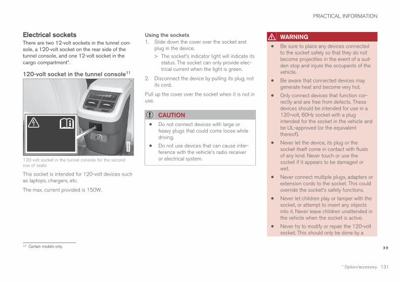
PRACTICAL INFORMATION
}}}}
* Option/accessory. 131
Electrical socketsThere are two 12-volt sockets in the tunnel con-sole, a 120-volt socket on the rear side of thetunnel console, and one 12-volt socket in thecargo compartment*.
120-volt socket in the tunnel console11
120-volt socket in the tunnel console for the secondrow of seats
This socket is intended for 120-volt devices suchas laptops, chargers, etc.
The max. current provided is 150W.
Using the sockets1. Slide down the cover over the socket and
plug in the device.
> The socket's indicator light will indicate itsstatus. The socket can only provide elec-trical current when the light is green.
2. Disconnect the device by pulling its plug, notits cord.
Pull up the cover over the socket when it is not inuse.
CAUTION
• Do not connect devices with large orheavy plugs that could come loose whiledriving.
• Do not use devices that can cause inter-ference with the vehicle's radio receiveror electrical system.
WARNING
• Be sure to place any devices connectedto the socket safely so that they do notbecome projectiles in the event of a sud-den stop and injure the occupants of thevehicle.
• Be aware that connected devices maygenerate heat and become very hot.
• Only connect devices that function cor-rectly and are free from defects. Thesedevices should be intended for use in a120-volt, 60Hz socket with a plugintended for the socket in the vehicle andbe UL-approved (or the equivalentthereof).
• Never let the device, its plug or thesocket itself come in contact with fluidsof any kind. Never touch or use thesocket if it appears to be damaged orwet.
• Never connect multiple plugs, adapters orextension cords to the socket. This couldoverride the socket's safety functions.
• Never let children play or tamper with thesocket, or attempt to insert any objectsinto it. Never leave children unattended inthe vehicle when the socket is active.
• Never try to modify or repair the 120-voltsocket. This should only be done by a
11 Certain models only.

||
PRACTICAL INFORMATION
132
trained and qualified Volvo service techni-cian.
Failure to follow the points above could resultin electrical shock and/or serious injury.
Status indicationAn LED (Light Emitting Diode) on the socketindicates its status:
Status indicator light Socket status Action
Steady green light The socket is providing current to a connected device. None.
Flashing orange light The socket's voltage converter is too hot (the connected device draws too muchcurrent, etc. or the temperature in the passenger compartment is very high).
Unplug the device, let the converter cool downand plug in the device again.
The connected device draws too much current (constantly or currently) or is notfunctioning properly.
None. The device should not be plugged into thesocket.
Indicator light off The socket has not detected a plugged in device. Be sure the device is correctly plugged into thesocket.
The socket is not active. Put the vehicle's ignition in at least mode I.
The socket has been active but has been deactivated. Start the engine and/or charge the start battery.
If a problem persists, have the socket checked bya trained and qualified Volvo service technician.

PRACTICAL INFORMATION
133
12-volt socket in the tunnel console
12-volt socket in the tunnel console for the front seats
12-volt socket in the tunnel console for the second rowof seats
The electrical sockets can be used for 12-voltdevices such as monitors, MP3 players and cell
phones. For the sockets to provide electrical cur-rent, the ignition must be in at least mode I.
WARNING
Always keep the sockets covered when not inuse.
CAUTION
Max. current provided is 10 A (120 W) if onesocket is used at a time. If both of the sock-ets in the tunnel console are used at thesame time, the max. current provided persocket is 7.5 A (90 W)
If a tire sealing system's compressor is beingused, no other device should be connected toany of the other sockets while the compres-sor is operating.
12-volt socket in the cargocompartment
12-volt socket in the cargo compartment
Fold down the cover to access the socket. Max.current provided is 10 A (120 W).
NOTE
The 12-volt socket in the cargo compartmentprovides electrical current even when the igni-tion is switched off. Using the socket whilethe engine is not running will drain the bat-tery.
Related information• Passenger compartment storage spaces
(p. 88)

PRACTICAL INFORMATION
134
Replacing bulbsThe halogen headlight bulbs12 can be replacedby the owner.
Models with LED (Light Emitting Diode) head-lights: these lights must be replaced by a trainedand authorized Volvo service technician.
NOTE
Halogen headlights are not available on allmodels or in all markets.
Consult your Volvo retailer if you are uncertainabout the type of headlights in your vehicle.
NOTE
• For information regarding any bulbs notmentioned in this section, please contactyour Volvo retailer or a trained andauthorized Volvo service technician.
• Always switch off the ignition before star-ting to replace a bulb.
• If an error message remains in the dis-play after a faulty bulb has been replaced,contact an authorized Volvo workshop.
• Condensation may form temporarily onthe inside of the lenses of exterior lightssuch as headlights, fog lights, or taillights.This is normal and the lights aredesigned to withstand moisture. Normally,condensation will dissipate after thelights have been on for a short time.
• The optional Active Bending Light bulbscontain trace amounts of mercury. Thesebulbs should always be disposed of by atrained and qualified Volvo service techni-cian.
CAUTION
Never touch the glass of bulbs with your fin-gers. Grease and oils from your fingers vapor-ize in the heat and will leave a deposit on thereflector, which will damage it.
WARNING
• The ignition should be switched off com-pletely (be in ignition mode 0) whenreplacing bulbs.
• If the engine has been running just priorto replacing bulbs in the headlight hous-ing, please keep in mind that componentsin the engine compartment will be hot.
Before the halogen headlight bulbs can bereplaced, that plastic covering over the headlighthousing has to be removed and the housing hasto be lifted out of the vehicle.
12 Halogen headlights are not available on all models.

PRACTICAL INFORMATION
}}
* Option/accessory. 135
To do so:
Lift the rubber strip by pressing in toward theengine compartment.
Release the pins in the plastic covering'sfour clips by pressing them down with ascrewdriver or similar object and remove thecovering.
Put the covering back in place in the reverseorder.
The low beam headlight bulb will be accessiblewhen the round rubber cover has been removed.
The turn signal, high beam, Daytime RunningLight and parking light bulbs will be accessiblewhen the plastic covering has been removed.
Front bulbs (vehicles with halogenheadlights)
Low beam
High beam
Parking light/Daytime Running Light
Turn signal
Fog light with corner illumination (LED)*
Taillight bulbs
Brake light (LED)
Side marker light (LED)
Backup light13
Taillight (LED)
Turn signal (LED)
Fog light (LED)
High-mounted brake light (LED)
Related information• Replacing low beam headlight bulbs (p. 137)
• Replacing High Beam headlight bulbs(p. 137)
13 Must be replaced by a trained and qualified Volvo service technician.

PRACTICAL INFORMATION
136
• Replacing front parking light bulbs (p. 138)
• Replacing front turn signal bulbs (p. 139)
• Removing the rectangular headlight cover(p. 136)
• Bulb specifications (p. 139)
Removing the rectangular headlightcoverMost of the bulbs in the headlight housing canbe accessed when the rectangular cover hasbeen removed.
Before the rectangular cover can be removed, theplastic covering must be removed, see the article"Replacing bulbs" for information.
1. Loosen the cover's four screws with a T20Torx screwdriver (1) but do not remove themcompletely (turning them 3–4 turns isenough).
2. Push the cover to the side.
3. Remove the cover.
Put the cover back in place in the reverse order.
Related information• Replacing bulbs (p. 134)

PRACTICAL INFORMATION
}}
137
Replacing low beam headlight bulbs
On models with halogen headlights, the lowbeam headlight bulb can be replaced by theowner.
Before the bulb can be replaced, the plastic cov-ering over the headlight housing has to beremoved, see the article "Replacing bulbs."
CAUTION
Never touch the glass of bulbs with your fin-gers. Grease and oils from your fingers vapor-ize in the heat and will leave a deposit on thereflector, which will damage it.
Driver's side bulb housing shown
1. Remove the low beam round rubber coverfrom the headlight housing.
2. Remove the connector from the bulb.
3. Remove the bulb by pressing it slightlyupward and then pulling it out.
4. Insert the bulb in the socket. The bulb's guid-ing pin should point straight up.
5. Press the connector into place.
6. Put the rubber cover back into place.
Related information• Replacing bulbs (p. 134)
• Bulb specifications (p. 139)
Replacing High Beam headlightbulbsOn models with halogen headlights, the HighBeam headlight bulb can be replaced by theowner.
Before the bulb can be accessed, the headlighthousing's rectangular cover must be removed,see the article "Removing the rectangular head-light cover."
CAUTION
Never touch the glass of bulbs with your fin-gers. Grease and oils from your fingers vapor-ize in the heat and will leave a deposit on thereflector, which will damage it.
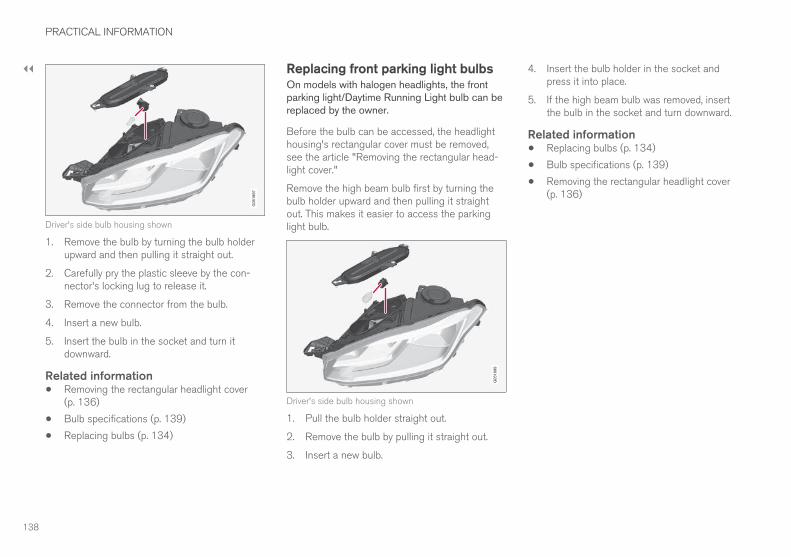
||
PRACTICAL INFORMATION
138
Driver's side bulb housing shown
1. Remove the bulb by turning the bulb holderupward and then pulling it straight out.
2. Carefully pry the plastic sleeve by the con-nector's locking lug to release it.
3. Remove the connector from the bulb.
4. Insert a new bulb.
5. Insert the bulb in the socket and turn itdownward.
Related information• Removing the rectangular headlight cover
(p. 136)
• Bulb specifications (p. 139)
• Replacing bulbs (p. 134)
Replacing front parking light bulbsOn models with halogen headlights, the frontparking light/Daytime Running Light bulb can bereplaced by the owner.
Before the bulb can be accessed, the headlighthousing's rectangular cover must be removed,see the article "Removing the rectangular head-light cover."
Remove the high beam bulb first by turning thebulb holder upward and then pulling it straightout. This makes it easier to access the parkinglight bulb.
Driver's side bulb housing shown
1. Pull the bulb holder straight out.
2. Remove the bulb by pulling it straight out.
3. Insert a new bulb.
4. Insert the bulb holder in the socket andpress it into place.
5. If the high beam bulb was removed, insertthe bulb in the socket and turn downward.
Related information• Replacing bulbs (p. 134)
• Bulb specifications (p. 139)
• Removing the rectangular headlight cover(p. 136)

PRACTICAL INFORMATION
139
Replacing front turn signal bulbsOn models with halogen headlights, the frontturn signal bulb can be replaced by the owner.
Before the bulb can be accessed, the headlighthousing's rectangular cover must be removed,see the article "Removing the rectangular head-light cover."
Driver's side headlight housing shown
1. Press the retaining catches together and pullthe bulb holder straight out.
2. The bulb holder and bulb must be replacedas one unit.
3. Press the new bulb holder into the socket.
Related information• Removing the rectangular headlight cover
(p. 136)
• Replacing bulbs (p. 134)
• Bulb specifications (p. 139) Bulb specificationsThe following specifications apply to models
equipped with halogen14 headlights. If otherbulbs need to be replaced, contact a trainedand qualified Volvo service technician.
Function [W]A Type
Low beam 55 H11
High Beam 65 H9
Front turn signal 24 PY24W
Daytime running light/parking light
21/5 W21/5W
A Watt
Related information• Replacing bulbs (p. 134)
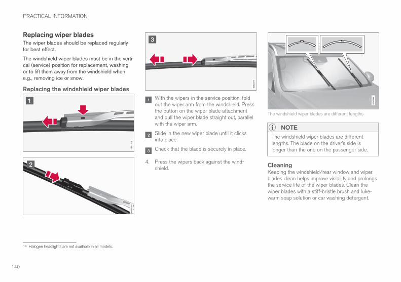
PRACTICAL INFORMATION
140
Replacing wiper bladesThe wiper blades should be replaced regularlyfor best effect.
The windshield wiper blades must be in the verti-cal (service) position for replacement, washingor to lift them away from the windshield whene.g., removing ice or snow.
Replacing the windshield wiper blades
With the wipers in the service position, foldout the wiper arm from the windshield. Pressthe button on the wiper blade attachmentand pull the wiper blade straight out, parallelwith the wiper arm.
Slide in the new wiper blade until it clicksinto place.
Check that the blade is securely in place.
4. Press the wipers back against the wind-shield.
The windshield wiper blades are different lengths
NOTE
The windshield wiper blades are differentlengths. The blade on the driver’s side islonger than the one on the passenger side.
CleaningKeeping the windshield/rear window and wiperblades clean helps improve visibility and prolongsthe service life of the wiper blades. Clean thewiper blades with a stiff-bristle brush and luke-warm soap solution or car washing detergent.
14 Halogen headlights are not available in all models.

PRACTICAL INFORMATION
}}
141
Replacing the tailgate wiper blade
1. Fold the wiper arm outward.
2. Grasp the inner section of wiper blade (at thearrow).
3. Use one end of the wiper blade as a lever tohelp release it from the wiper arm.
4. Press the new wiper blade until it clicks intoplace and check that it seats securely.
5. Fold the wiper arm back toward the tailgatewindow.
Related information• Windshield wipers in the service position
(p. 141)
• Refilling the windshield washer fluid reservoir(p. 142)
Windshield wipers in the servicepositionThe windshield wiper blades must be in the verti-cal (service) position for replacement, washingor to lift them away from the windshield whene.g., removing ice or snow.
Wipers in the service position
CAUTION
Be sure the wiper blades are not frozen inposition before attempting to move them tothe service position.
Putting the windshield wipers in theservice positionThe service position can be activated while thevehicle is stationary and the wipers are not acti-vated.
The service position can be activated in two waysfrom the center display:
Via Function view
– From Function view, tap the Wiper ServicePosition button. The indicator light in thebutton will illuminate when the service posi-tion is activated.
> The windshield wipers will move to thevertical position.
Via Settings
1. Tap Settings in the center display's Topview.
2. Tap My Car Wipers
3. Tap the Wiper Service Position box.
> The windshield wipers will move to thevertical position.
Deactivating service positionThe service position can be deactivated in twoways from the center display:

||
PRACTICAL INFORMATION
* Option/accessory.142
Via Function view
– From Function view, tap the Wiper ServicePosition button. The indicator light in thebutton will go out when the service positionis deactivated.
Via Settings
1. Tap Settings in the center display's Topview.
2. My Car Wipers
3. Tap the Wiper Service Position to deselectthe box.
The wipers will also leave the service position if:
• The wipers are activated.
• The windshield washers are activated.
• The rain sensor is activated.
CAUTION
If the wiper arms have been folded out fromthe windshield while in the service position,fold them back against the windshield beforereturning the wipers to the normal position tohelp avoid scratching the paint on the hood.
Related information• Replacing wiper blades (p. 140)
Refilling the windshield washer fluidreservoirWasher fluid helps keep the windshield, tailgatewindow and headlights clean.
The windshield and headlight washers* share acommon reservoir. Open the blue cap to refillwasher fluid (see the illustration for the locationof the reservoir).
During cold weather, the reservoir should be filledwith windshield washer solvent containing anti-freeze. Use Volvo Original Washer Fluid or theequivalent with a recommended pH valuebetween 6 and 8 in a 1:1 solution.
When there is approx. 1 qt (1 liter) of washerfluid remaining in the reservoir, a text message
and the symbol will be displayed in theinstrument panel.

PRACTICAL INFORMATION
}}
143
Volume:
• Models with headlight washers: 5.8 qts(5.5 liters).
• Models without headlight washers: 3.7 qts(3.5 liter).
Related information• Opening and closing the hood (p. 143)
• Engine compartment overview (p. 89)
Opening and closing the hoodThe hood is opened by releasing it from the pas-senger compartment and then by using the han-dle under the front edge of the hood.
Opening
With the hood completely closed, pull thecontrol (located to the left of the brakepedal).
Turn the handle under the front edge of thehood counterclockwise to release it from thelock and lift.
Warning–hood not closedWhen the hood lock has been com-pletely released, this symbol and agraphic will illuminate in the instrumentpanel and an audible signal will be
given. If the vehicle begins to roll, the audible sig-nal will be repeated several times.
NOTE
If the warning symbol remains on or if theaudible signal is given even if the hood iscompletely closed and locked, consult atrained and qualified Volvo service technician.

||
PRACTICAL INFORMATION
* Option/accessory.144
Closing1. Press down the hood until it begins to close
due to its own weight.
2. When the handle under the front edge of thehood is in the lock, press down on the hoodto close it completely.
WARNING
• Be sure the hood is completely unob-structed while it is being closed.
• Check that the hood locks properly whenclosed. It must audibly lock on both sides.
• Never drive if the hood is not completelyclosed and locked.
• While driving, if there are any indicationsthat the hood is not locked in the closedposition, stop safely as soon as possibleand close it completely.
Hood completely closed
Related information• Engine compartment overview (p. 89)
Detachable trailer hitch*Volvo recommends the use of Volvo trailerhitches that are specially designed for the vehi-cle.
NOTE
The optional detachable trailer hitch may notbe available in all markets or on all models.Consult your Volvo retailer.
Ball holder
Cotter pin
Hitch assembly
Locking bolt
Safety wire attachment bracket
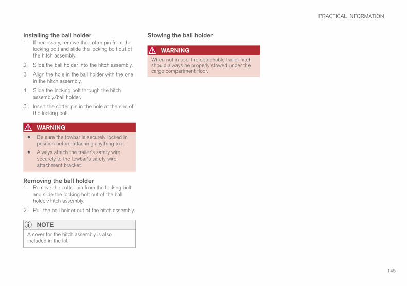
PRACTICAL INFORMATION
145
Installing the ball holder1. If necessary, remove the cotter pin from the
locking bolt and slide the locking bolt out ofthe hitch assembly.
2. Slide the ball holder into the hitch assembly.
3. Align the hole in the ball holder with the onein the hitch assembly.
4. Slide the locking bolt through the hitchassembly/ball holder.
5. Insert the cotter pin in the hole at the end ofthe locking bolt.
WARNING
• Be sure the towbar is securely locked inposition before attaching anything to it.
• Always attach the trailer's safety wiresecurely to the towbar's safety wireattachment bracket.
Removing the ball holder1. Remove the cotter pin from the locking bolt
and slide the locking bolt out of the ballholder/hitch assembly.
2. Pull the ball holder out of the hitch assembly.
NOTE
A cover for the hitch assembly is alsoincluded in the kit.
Stowing the ball holder
WARNING
When not in use, the detachable trailer hitchshould always be properly stowed under thecargo compartment floor.


FUSES

FUSES
148
FusesThe fuses help protect the vehicle's electricalcomponents from overloading or short circuits.
WARNING
Never use metal objects or fuses with higheramperage than those stated on the lists offuses. Doing so could seriously damage oroverload the vehicle's electrical system.
If an electrical component fails to function, thismay be due to a blown fuse. If the same fuseblows repeatedly, this indicates a problem withthe component, which should be inspected by atrained and qualified Volvo service technician.
Location of the fuseboxes
Engine compartment
Under the glove compartment
Cargo compartment
Related information• Replacing fuses (p. 148)
• Fuses in the cargo compartment (p. 157)
• Fuses in the engine compartment (p. 149)
• Fuses in the passenger compartment(p. 153)
Replacing fusesThe fuses help protect the vehicle's electricalcomponents from overloading or short circuits.
Fuse replacement1. See the list of fuse boxes for their locations.
2. Pull the fuse straight out and examine it fromthe side to see if the curved metal wire in thefuse is intact.
3. If the wire is broken, insert a new fuse of thesame color and amperage (written on thefuse).
WARNING
Never use metal objects or fuses with higheramperage than those stated on the followingpages. Doing so could seriously damage oroverload the vehicle's electrical system.
Related information• Fuses (p. 148)
• Fuses in the cargo compartment (p. 157)
• Fuses in the engine compartment (p. 149)
• Fuses in the passenger compartment(p. 153)

FUSES
}}
149
Fuses in the engine compartmentThe fuses in the engine compartment help pro-tect electrical components such as engine andbrake functions.
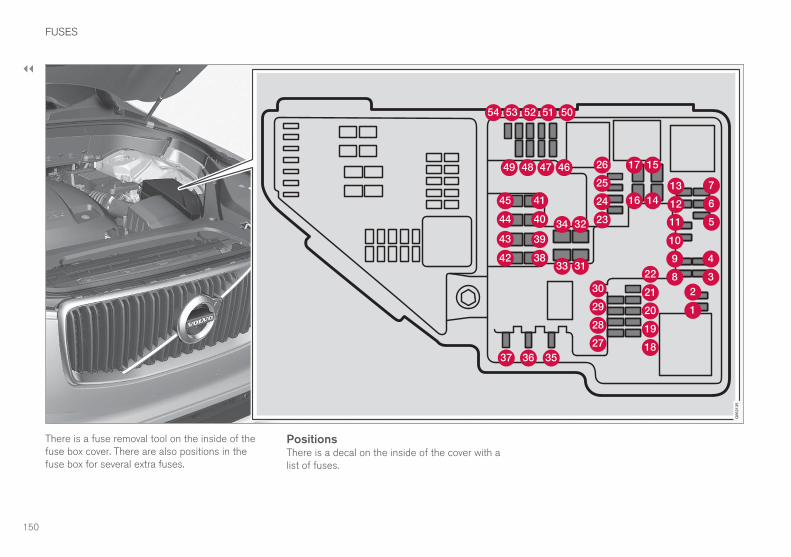
||
FUSES
150
There is a fuse removal tool on the inside of thefuse box cover. There are also positions in thefuse box for several extra fuses.
PositionsThere is a decal on the inside of the cover with alist of fuses.

FUSES
}}
* Option/accessory. 151
• Fuses 1–13, 18–30, 35–37 and 46–54 arecalled "Micro".
• Fuses 31–34 and 38–45 are called "MCase"and should only be replaced by a trained andqualified Volvo service technician.
Function A
– –
– –
– –
Ignition coils, spark plugs 15
Oil pump solenoid Electromag-netic relay A/C, Center oxygensensor
15
Vacuum regulators, Valve 7.5
Engine control module, Actuator,throttle unit, Turbocharger valve
20
Engine control module 5
– –
Solenoids, Valve, Coolant ther-mostat
10
Spoiler shutter control module,Radiator shutter control module
5
Front/rear oxygen sensors 15
Function A
Engine control module 20
Starter motor 40
Starter motor Shunt
– –
– –
– –
– –
– –
– –
– –
– –
12-volt socket in the front tun-nel console
15
12-volt socket on the rear sideof the tunnel console
15
12-volt socket in the cargo com-partment
15
– –
– –
Function A
– –
– –
Heated windshield*, driver side Shunt
Heated windshield*, driver side 40
Headlight washers* 25
Windshield washer 25
Transmission control module 15
Horn 20
Alarm siren 5
Brake system control module(valves, parking brake)
40
Windshield wipers 30
Tailgate window washer 25
Heated windshield*, passengerside
40
– –
Brake system control module(ABS pump)
40
– –
||
FUSES
* Option/accessory.152
Function A
Heated windshield*, passengerside
Shunt
Feed when ignition is switchedon to: engine control module,transmission components, elec-trical power steering, centralelectrical module;
Brake system control module
5
– –
Passenger side headlight 7.5
Passenger's side headlight, cer-tain LED models
7.5
– –
– –
Battery connection module 5
Air bags; Occupant Weight Sen-sor (OWS)
5
Driver side headlight 7.5
Driver's side headlight, certainLED models
7.5
Accelerator pedal sensor 5
Related information• Fuses (p. 148)
• Replacing fuses (p. 148)

FUSES
}}
153
Fuses in the passengercompartmentThe fuses in the passenger compartment(located under the glove compartment) help pro-
tect electrical components such as the 120-voltsocket, displays and door modules.
There is a fuse removal tool on the inside of thefuse box covers. There are also positions in thefuse box for several extra fuses.

||
FUSES
154

FUSES
}}
* Option/accessory. 155
Positions• Fuses 1, 3–21, 23–36, 39–53 and 55–59
are called "Micro".
• Fuses 2, 22, 37–38 and 54 are called"MCase" and should only be replaced by atrained and qualified Volvo service technician.
Function A
– –
120-volt socket on the rear side ofthe tunnel console*
30
– –
Alarm system movement sensorA 5
Media player 5
Instrument panel 5
Center console buttons 5
Sun sensor 5
– –
– –
Steering wheel module 5
Module for start knob and parkingbrake
5
Function A
Heated steering wheel* module 15
– –
– –
– –
– –
Climate system control module 10
– –
On-board diagnostics (OBDII) 10
Center display 5
Climate system blower module(front)
40
USB hub 5
Instrument lighting; Courtesy light-ing; Rearview mirror auto-dim func-tion; Rain and light sensor; Reartunnel console keypad*; Powerfront seats*; Rear door control pan-els
7.5
Control module for driver supportfunctions
5
Function A
Panorama roof and sun shade* 20
Head-up display* 5
Courtesy lighting 5
– –
Ceiling console display (seat beltreminder, front passenger side air-bag indicator)
5
– –
Humidity sensor 5
Rear passenger-side door module 20
Fuses in the cargo compartment 10
Internet connection/Volvo On Callcontrol modules
5
Rear driver-side door module 20
Infotainment control module(amplifier)
40
Climate system blower module(rear)*
40
Multi-band antenna module 5
Front seat massage function 5

||
FUSES
* Option/accessory.156
Function A
– –
Tailgate window wiper 15
Fuel pump control module 15
– –
– –
Driver side front seat heating* 15
Passenger side front seat heating* 15
Coolant pump 10
– –
Front driver-side front door module 20
Active chassis control module* 20
– –
Sensus control module 10
– –
– –
Front passenger-side front doormodule
20
Function A
– –
– –
Circuit breaker for fuses 53 and 58 15
A Certain markets only
Related information• Fuses (p. 148)
• Replacing fuses (p. 148)
• Fuses in the engine compartment (p. 149)
• Fuses in the cargo compartment (p. 157)

FUSES
}}
* Option/accessory. 157
Fuses in the cargo compartmentThe fuses in the cargo compartment help pro-tect electrical components such as powerseats*, airbags and seat belt tensioners.
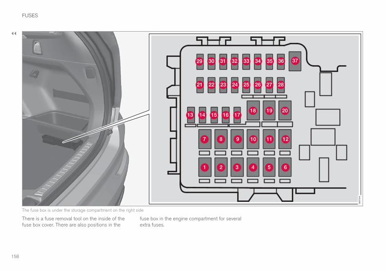
||
FUSES
158
The fuse box is under the storage compartment on the right side
There is a fuse removal tool on the inside of thefuse box cover. There are also positions in the
fuse box in the engine compartment for severalextra fuses.

FUSES
* Option/accessory. 159
Positions• Fuses 13–17 and 21–36 are called "Micro".
• Fuses 1–12, 18–20 and 37 are called"MCase" and should only be replaced by atrained and qualified Volvo service technician.
Function A
Heated rear window 30
– –
Pneumatic suspension* compressor 40
Rear auxiliary electric heater (pas-senger side)
30
– –
Rear auxiliary electric heater (driverside)*
30
– –
– –
Power tailgate* 25
Power front seat (passenger side)*module
20
Trailer hitch* control module 40
Seat belt tensioner module (pas-senger side)
40
Function A
Internal relay windings 5
– –
Foot movement detection modulefor opening the power tailgate*
5
– –
Module for electrically folding thirdrow seats*
20
Trailer hitch* control module 25
Power front seat (driver seat* mod-ule
20
Seat belt tensioner module (driverside)
40
Parking camera* 5
– –
– –
– –
– –
Airbag and seat belt tensionermodules
5
– –
Function A
Heated rear seat (driver side)* 15
– –
Blind Spot Information (BLIS)*,Control module for exterior audiblereverse warning (certain marketsonly)
5
– –
Seat belt tensioner modules 5
Emission system actuator 5
– –
All Wheel Drive control module* 15
Heated rear seat (passenger side)* 15
– –
Related information• Replacing fuses (p. 148)
• Fuses (p. 148)
• Fuses in the passenger compartment(p. 153)
• Fuses in the engine compartment (p. 149)


SPECIFICATIONS

SPECIFICATIONS
162
Label informationThe labels in your vehicle provide informationsuch as the chassis number, paint code, tireinflation pressure, etc.

SPECIFICATIONS
}}
163
Location of labels
Generic illustration - details may vary slightly depending on model/market

||
SPECIFICATIONS
164
List of labelsVehicle Emission Control Information. (A)US models, (B) Canadian models. Your Volvois designed to meet all applicable emissionstandards, as evidenced by the certificationlabel on the underside of the hood. For fur-ther information regarding these regulations,please consult your Volvo retailer.
Engine oil. This label contains the recom-mended engine oil specifications.
Vehicle Identification Number (VIN). TheVIN plate is located on the top left surface ofthe dashboard. The Vehicle IdentificationNumber (VIN) should always be quoted in allcorrespondence concerning your vehicle withthe retailer and when ordering parts.
Tire inflation pressures. This label indicatesthe correct inflation pressures for the tiresthat were on the vehicle when it left the fac-tory.
Federal Motor Vehicle Safety Standards(FMVSS) specifications (USA) and Minis-try of Transport (CMVSS) standards(Canada). Your Volvo is designed to meet allapplicable safety standards, as evidenced bythe certification label on the driver's side B-pillar (the structural member at the side ofthe vehicle, at the rear of the driver's dooropening). This label also includes codes forpaint color, etc. For further information regar-ding these regulations, please consult your
Volvo retailer. U.S. models have the upperdecal; Canadian models have the lower one.

SPECIFICATIONS
}}
* Option/accessory. 165
DimensionsThe following table lists your vehicle's mostimportant dimensions.
Dimension In.
(mm)
A Ground clearance (curbweight + 2 people)A
8.9 (227)
B Wheelbase 117.5 (2984)
C Length 194.9 (4950)
D Load length, floor, seat-back down
80.3 (2040)
49.6 (1260)B
Dimension In.
(mm)
E Load length, floor 48.0 (1220)C
21.8 ( 554)D
F Height 69.9 (1776)
G Load height 32.1 (816)
Dimension In.
(mm)
H Track, front (models with-out pneumatic suspen-sion)
65.9 (1673)E
65.6 (1665)F
Track, front (models withpneumatic suspension)
66.0 (1676)E
65.7 (1668)F

||
SPECIFICATIONS
166
Dimension In.
(mm)
I Track, rear (models with-out pneumatic suspen-sion)
65.8 (1675)E
66.1 (1667)F
Track, rear (models withpneumatic suspension)
66.1 (1679)E
65.8 (1671)F
J Load width, floor 46.9 (1192)
K Width 75.7 (1923)G
76.0 (1931)H
77.1 (1958)I
L Width incl. door mirrors(folded out)
84.3 (2140)
M Width incl. door mirrors(folded in)
79.1 (2008)
A Varies slightly depending on tire size, chassis options, etc.B From the second row of seats in 7-seat models*.C 5-seat modelD 7-seat modelE Models with 20, 21 and 22 in. wheels.F Models with 18 and 19 in. wheels.G Chassis width.H Width on models with 18 and 19 in. wheels.I Width on models with 20, 21 and 22 in. wheels.
Related information• Weights (p. 167)

SPECIFICATIONS
}}
167
WeightsThe following table lists important weight datafor your vehicle.
Category USA Canada
Gross vehicle weight
7-seat, 4-cyl. AWD (All Wheel Drive)
7-seat 4-cyl. FWD (Front Wheel Drive)
5-seat, 4-cyl. AWD
5-seat 4-cyl. FWD
6,060 lbs
6,005 lbs
6,005 lbs
6,005 lbs
2,750 kg
2,725 kg
2,725 kg
2,725 kg
Capacity weight
7-seat, 4-cyl.
5-seat, 4-cyl.
1,210 lbs
1,100 lbs
550 kg
500 kg
Permissible axle weights, front
7-seat, 4-cyl. AWD
7-seat, 4-cyl. FWD
5-seat, 4-cyl. AWD
5-seat, 4-cyl. FWD
2,885 lbs
2,865 lbs
2,865 lbs
2,865 lbs
1,310 kg
1,300 kg
1,300 kg
1,300 kg
Permissible axle weights, rear
7-seat, 4-cyl. AWD
7-seat, 4-cyl. FWD
5-seat, 4-cyl. AWD
5-seat, 4-cyl. FWD
3,280 lbs
3,280 lbs
3,280 lbs
3,280 lbs
1,490 kg
1,490 kg
1,490 kg
1,490 kg

||
SPECIFICATIONS
168
Category USA Canada
Curb weight
7-seat, 4-cyl.
5-seat, 4-cyl.
4,430-4,680 lbs
4,290-4,550 lbs
2,050-2,150 kg
2,010-2,090 kg
Max. roof load 220 lbs 100 kg
Max. trailer weights Without brakes: 1,650 lbs
With brakes (AWD): 5,000 lbs
With brakes (FWD): 4,000 lbs
Without brakes: 750 kg
With brakes (AWD): 2,250 kg
With brakes (FWD): 1,800 kg
Max. tongue weight AWD: 500 lbs
FWD: 400 lbs
AWD: 225 kg
FWD: 180 kg
CAUTION
• When loading the vehicle, the maximumgross vehicle weight and permissible axleweights may not be exceeded.
• The maximum trailer weights listed areonly applicable for altitudes up to 3280 ft(1,000 m) above sea level. With increas-ing altitude the engine power and there-fore the car's climbing ability are impairedbecause of the reduced air density, sothe maximum trailer weight has to bereduced accordingly. The weight of thecar and trailer must be reduced by 10%for every further 3280 ft (1,000 m) (orpart thereof).
SPECIFICATIONS
* Option/accessory. 169
Air conditioning refrigerantThe air conditioning system in your car containsa CFC-free refrigerant.
A/C decal
R134a decal
Refrigerant
Weight Type
1.65 lbs (750 g)
2.2 lbs (1000 g) on models with A/Cfor the third row of seats*
R134a
WARNING
The air conditioning system contains R134arefrigerant under pressure. Service andrepairs may only be carried out by a trainedand qualified Volvo service technician.
Compressor oil
Volume Type
2.03 fl. oz. (60 ml)
2.71 fl. oz. (80 ml) on models withA/C for the third row of seats*
PAG SP-A2
EvaporatorThe A/C system' s evaporator may never berepaired or replaced with a previously used evap-orator. A new evaporator must be certified andmarked according to SAE J2842.
Brake fluid specification and volumeBrake fluid transfers braking force when thebrake pedal is depressed to the master cylinderand to the slave cylinders on each wheel.
Topping up or replacing brake fluid should onlybe done by a trained and qualified Volvo servicetechnician.
Specification: Volvo Original Dot 4 class 6 orequivalent

SPECIFICATIONS
170
Coolant specificationsCoolant specifications.
Specification: Coolant with corrosion inhibitormixed with water (50/50 mix), see packaging.
Consult a Volvo retailer if you are uncertain.
Different types of coolant should not be mixed tohelp avoid health risks.

SPECIFICATIONS
}}
171
Engine specificationsThe following table provides technical data forthe respective engines. Engine specifications forSpecial Edition vehicles may vary.
Not all engines listed here are available in allmarkets.
Specification T6 AWD
Engine designation B4204T27
Output (kW/rps) 235/95
Output (hp/rpm) 316/5700
Torque (Nm/rps) 400/37–90
Torque (ft. lbs./rpm) 295/2,200–5,400
No. of cylinders 4
Specification T5
Engine designation B4204T23
Output (kW/rps) 187/92
Output (hp/rpm) 250/5,500
Torque (Nm/rps) 350/25–80
Torque (ft. lbs./rpm) 258/1,500-4,800
No. of cylinders 4

||
SPECIFICATIONS
172
Related information• Engine oil specifications and volume
(p. 173)
• Coolant specifications (p. 170)
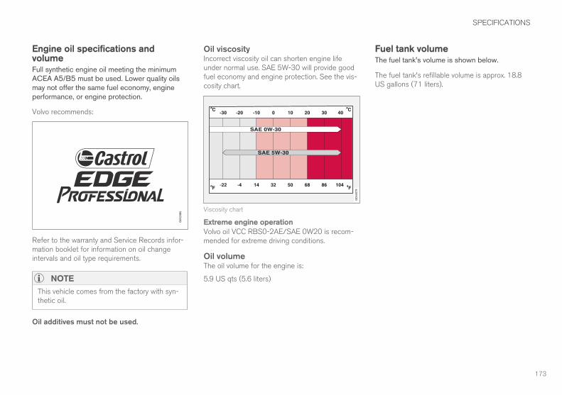
SPECIFICATIONS
173
Engine oil specifications andvolumeFull synthetic engine oil meeting the minimumACEA A5/B5 must be used. Lower quality oilsmay not offer the same fuel economy, engineperformance, or engine protection.
Volvo recommends:
Refer to the warranty and Service Records infor-mation booklet for information on oil changeintervals and oil type requirements.
NOTE
This vehicle comes from the factory with syn-thetic oil.
Oil additives must not be used.
Oil viscosityIncorrect viscosity oil can shorten engine lifeunder normal use. SAE 5W-30 will provide goodfuel economy and engine protection. See the vis-cosity chart.
Viscosity chart
Extreme engine operationVolvo oil VCC RBS0-2AE/SAE 0W20 is recom-mended for extreme driving conditions.
Oil volumeThe oil volume for the engine is:
5.9 US qts (5.6 liters)
Fuel tank volumeThe fuel tank's volume is shown below.
The fuel tank's refillable volume is approx. 18.8US gallons (71 liters).

SPECIFICATIONS
174
Tire inflation pressure tableThe following tire pressures are recommendedby Volvo for your vehicle. Refer to the tire infla-
tion placard for information specific to the tiresinstalled on your vehicle at the factory.
Tire sizes: XC90 Cold tire pressure for up to five or seven persons (depending on seating capacity)
Front
psi (kPa)
Rear
psi (kPa)
235/60 R18
235/55 R19
275/45 R20
275/40 R21
275/35 R22
38 (260) 38 (260)
Temporary spare tire
T125/80 R18
60 (420) 60 (420)
Related information• Checking tire inflation pressure (p. 111)

SPECIFICATIONS
175
Transmission fluid specification andvolumeUnder normal driving conditions the transmissionfluid does not need to be changed during itsservice life. However, it may be necessary underadverse driving conditions.
Transmission: TG-81SC
Specification: Transmission fluid AW-1


INDEX
177
A
Accessory installation warning 14, 18
Airbags
disconnecting the front passenger’s
side 63
front 59, 60
inflatable curtain 67
side impact 66
Alarm
automatically arming/disarming 101
Apps
changing settings 37
Automatic locking retractor 71
Automatic transmission
oil 175
Axle weight 109
B
Booster cushion, integrated 81, 82, 84
Booster cushions 77
Brake system
fluid 169
Bulbs 138
replacing 134
specifications 139
C
Capacity weight 109, 167
Cargo compartment
fuses 157
raising/lowering the level 91
Cargo compartment, steel grid 96
Cargo compartment cover 98
Cargo net 95
Cargo space 91
Center display
changing settings 24
keyboard 25
navigating in 32
overview 22
screen in the center console 38
symbols in the status bar 37
Chains 111
Changing a wheel 113
Child restraints
recalls and registration 71
Child restraint systems 71
booster cushions 77
convertible seats 75
infant seats 73
ISOFIX/LATCH anchors 78
top tether anchors 80
Child safety 69
booster cushions 77
child restraint systems 71, 79
convertible seats 75
infant seats 73
Child seats
lower attachment points 79
Climate system
refrigerant 169
Convertible seats 75
Coolant 170
Crash event data 20
Crash mode 68
Curb weight 109, 167
D
Digital owner's manual 44, 45
Dimensions 165
Disconnecting the front passenger’s airbag 63
Driver distraction warning 14, 18
INDEX

INDEX
178
E
Electrical sockets 131
Emergency locking retractor 71
Engine compartment
fuses 149
Engine compartment overview 89
Engine oil 173
Engine specifications 171
Environment 9
Eyelets for anchoring loads 98
F
Flat tires
repairing with tire sealing system 123,
125, 129
Fluid specifications 169, 170, 175
Front airbags 59, 60
disconnecting passenger’s side airbag 63
Fuel filler door, opening 102
Fuel requirements 101
Function view 30
Fuses 148
cargo compartment 157
engine compartment 149
passenger compartment 153
Fuses, replacing 148, 149, 153, 157
G
Gasoline requirements 101
Glossary of tire terminology 107
Glove compartment 90
Grocery bag holder 94
Gross vehicle weight 109
Gross vehicle weight (GVW) 167
H
Headlights
removing cover 136
High beam bulb, replacing 137
Hood, opening/closing 143
I
ID, Volvo 21
Infant seats 73
Inflatable Curtain 67
Inflation pressure 111
Inflation pressure table 174
Intellisafe 10
ISOFIX/LATCH anchors 78
J
Jack 114
location of 114, 116
L
Labels
list of 164
location of 163
LATCH anchors 78
Load anchoring eyelets 98
Loading the vehicle 91, 109
Low beam bulb, replacing 137
N
Net
cargo 95

INDEX
179
O
Occupant safety 50
Occupant weight sensor 63
Octane recommendations 101
Oil quality 173
On-board Diagnostic socket 14
Opening the hood 143
Option/accessory 42
Options 14
Owner's information
mobile applications 14
Owner's manual 10
P
Parking light bulb, replacing 138
Passenger compartment
fuses 153
Permissible axle weight 167
Pregnancy, using seat belts during 52
R
Recalls 52
Recalls, child restraints 71
Refrigerant (A/C system) 169
Refueling 101
fuel filler door 102
Registering child restraints 71
Replacing bulbs 134
Replacing fuses 148, 149, 153, 157
Reporting safety defects 51
Roadside Assistance 8
S
Safety, occupant 50
Safety defects, reporting 51
Safety mode 68
Seat belt
reminder 58
Seat belts
Automatic locking retractor/Emergency
locking retractor 71
buckling 56
pretensioners 54, 55
reminder 58
securing child restraint systems 73, 75, 77
unbuckling 56
use during pregnancy 52
using 54
Sensus 11
Side impact airbags 66
Snow chains 111
Snow tires 111
Specifications
bulbs 139
Starting the vehicle
after a crash (crash mode) 68
Steel grid in cargo compartment 96
Storage compartments 88
Studded tires 111
Sun visor 91
T
Tailgate wipers 140
Technician certification 47
Temporary spare tire 114
Tire inflation pressure 174
Tire Pressure Monitoring System 118, 121
calibrating 122
INDEX
180
Tire Pressure Monitoring System (TPMS) 122
Tires 103, 113
changing 113
changing from summer to winter 108
glossary of terms 107
improving economy 103
inflation pressure 111
inflation pressure table 174
installing (mounting) a wheel on the
vehicle 118
rotation 104
snow 111
spare 114
specifications 105
storing 104
studded 111
tire pressure monitoring system 118, 121
tire sealing system 123, 125, 129
tread wear indicator 109
uniform tire quality grading 110
wheel bolts 116
Tire sealing system 123, 125, 129
Top tether anchors (child restraint sys-
tems) 80
Towbar 144
Towing a trailer
trailer hitch 144
Trailer hitch 144
Trailer towing
trailer hitch 144
Transmission
oil 175
Tread wear indicator 109
Turn signals
changing bulbs 139
U
Uniform Tire Quality Grading 110
V
Vehicle Event Data 20
Vehicle information 8
Vehicle loading 91, 109
Vehicle weights 167
Volvo and the environment 9
Volvo ID 21
Volvo programs 8
Volvo Roadside Assistance 8
W
Washer fluid 142
Wheels
changing 113, 116
storing 104
Whiplash Protection System 53
Windows
laminated glass 47
Windshield washer fluid reservoir 142
Windshield wiper blades 140
Windshield wipers
service position 141
Wiper blades
replacing 140, 141
replacing tailgate wiper 140


TP 23685 (English - USA & Canada), AT 1717, MY18, Copyright © 2000-2017 Volvo Car Corporation