owner's manual - the best built sprayers in - fimco industriesfm831).pdf ·...
TRANSCRIPT

Warranty/Parts/ServiceFor home usage, products are warranted for one year from date of purchase against manufacturer or workmanship defects.
Commercial users have a 90 day warranty.
Your authorized dealer is the best source of replacement parts and service. To obtain prompt, efficient service, always remember to give the following information...
- Correct Part Description and/or part number. - Model number/Serial number of your sprayer.
Part descriptions and part numbers can be obtained from the illustrated parts list section(s) of this manual.
Whenever you need parts or repair service, contact your distributor/dealer first. For warranty work, always take your original sales slip, or other evidence of purchase date, to your distributor/dealer.
40 Gal. Corrosion-Resistant Polyethylene Tank•12 Volt Diaphragm Pump, 2.1 g.p.m. - 60 p.s.i.•Deluxe Pistol-Grip Handgun•25 Ft. Handgun Hose•25 Ft. max. vertical throw, 35 Ft. max. horizontal throw•Low Profile Trailer & Tank•15/600 x 6 2-Ply Pneumatic Tires•Pressure Gauge•Adjustable Pressure•5-Nozzle Boom Assembly, 100" Spray Coverage•Breakaway Outer Boom Members•
Technical Specifications
Form No. 831 [5004604 (01/14)] Printed in the U.S.A.
Model: TR-40-EX (5301338)(40 Gallon Lawn & Garden Trailer Sprayer w/5-Nozzle Boom Assembly)
Owner's Manual
General InformationThank you for purchasing this product. The purpose of this manual is to assist you in operating and maintaining your lawn & garden trailer sprayer. Please read it carefully, as it furnishes information which will help you achieve years of trouble-free operation.
Your sprayer has been partially assembled at the factory. Follow the instructions below to complete the assembly of this unit. (Refer to the exploded view drawing later in this manual)
1. Mount the axle to the frame, securing it with the hardware provided.2. Slide a wheel (valve stem out) onto each end of the axle, then use a cotter pin to secure the wheels in place.3. Bolt the boom brackets to the back of the frame. (if not already done)4. Bolt the boom assembly to the boom brackets. The tips need to be approximately 18" above the spraying surface. Secure in place with (2) u-bolts and (4) nuts provided. The outer boom members need to fold rearward.5. Thread the pressure gauge into the end fitting on the manifold assembly. Use a good grade of sealant, to insure no leaks.6. Attach the 'loose' boom feeder hose to the hose barb on the manifold assembly and to the nylon feeder "cross" on the boom. Secure in place with the provided hose clamps.8. Connect the electrical hook-up to the end of your pump and clip the clips to a fully charged battery. The red wire must be connected to the positive (+), and the black wire should be connected to the negative (-).
Assembly Instructions
1000 FIMCO Lane, P.O. Box 1700, North Sioux City, SD 57049Toll Free Phone: 800-831-0027 : Toll Free Fax: 800-494-0440
www.fimcoindustries.com
Time Required in seconds to travel a distance of:
17 344.05.06.07.0
9.08.0
10.07.66.8
9.78.5
1411
1514
1917
2327
100 Ft.
68 sec.2.03.0
1.0(Miles per Hour)Speed in M.P.H.
Speed Chart
136 sec.3423 45
68
200 Ft.
51
2320
2629
4134
205 sec.
300 Ft.
10268
Gallons Per 1000 Sq. Ft. - Based on Water
MPH
Pressure
Pressure
AIXR11002VP
Number
AIXR11002VP
Number
Tip
Tip
18"
HeightSpray
18"
HeightSpray
.27.34.45.680.2040
Gallons Per Acre - Based on Water
(GPM)Capacity
(GPM)Capacity
0.2040
302015
(psi)
0.170.140.12
302015
(psi)
0.170.140.12
29.859.6
MPH
.58
.48
.41
2
50.441.635.6MPH
1MPH
25.220.817.8
2
.23
.19
.16MPH
5
11.910.18.37.1
MPH5
14.919.8
.29
.24
.20MPHMPH
.39
.32
.27
3 4
12.610.4
MPHMPH
16.813.811.8
3
8.9
4
7.49.98.46.95.9
MPH6
6.35.24.5
8
Spray Tip Rate Chart(20" Spacing)
110° wide, tapered flat spray angle with air induction technology for better drift management. Made of 2-piece UHMWPE polymer
construction which provides excellent chemical resistance, including acids, as well as exceptional wear life. Compact size to
prevent tip damage. Removable pre-orifice. Excellent for systemic products and drift management.
Page 2
OperationYour sprayer is equipped with (1) ON/OFF switch. It is on the wire assembly that you hook up to your battery. The "-" is the "ON" position and the "o" is the "OFF" position for the switch. Make sure the switch is depressed in the "-" position for operation.
The pump is equipped with an electronic pressure switch that is factory pre-set for it to shut off at 60 p.s.i.. This switch assembly is the 'square box' on the head portion of the pump.
Always fill the tank with a desired amount of water first, and then add the chemical slowly, mixing as you pour the chemical into the tank. You may use the handgun to spray into the solution in order to mix the chemical and water.
The pumping system draws solution from the tank, through the strainer/filter, and to the pump. The pump forces the solution under pressure to the handgun and/or boom nozzles.
Open the handgun by squeezing the handle lever.•
Rotating the adjustable nozzle tip on the handgun will change •the tip pattern from a straight stream to a cone pattern (finer mist).
This sprayer is designed to be towed behind a garden tractor.
The nozzles on the boom will spray an 100 inch wide swath. Check the nozzle pattern by spraying water on a concrete surface. Raise the boom to a higher mounting position to get more spray pattern overlap, if desired.
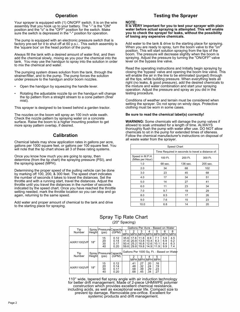
CalibrationChemical labels may show application rates in gallons per acre, gallons per 1000 square feet, or gallons per 100 square feet. You will note that the tip chart shows all 3 of these rating systems.
Once you know how much you are going to spray, then determine (from the tip chart) the spraying pressure (PSI), and the spraying speed (MPH).
Determining the proper speed of the pulling vehicle can be done by marking off 100, 200, & 300 feet. The speed chart indicates the number of seconds it takes to travel the distances. Set the throttle and with a running start, travel the distances. Adjust the throttle until you travel the distances in the number of seconds indicated by the speed chart. Once you have reached the throttle setting needed, mark the throttle location so you can stop and go again, returning to the same speed.
Add water and proper amount of chemical to the tank and drive to the starting place for spraying.
Testing the SprayerNOTE:It is VERY important for you to test your sprayer with plain water before actual spraying is attempted. This will enable you to check the sprayer for leaks, without the possibility of losing any expensive chemicals.
Add water to the tank & drive to the starting place for spraying. When you are ready to spray, turn the boom valve to the "on" position. This will start solution spraying from the tips of the boom. The pressure will decrease slightly when the boom is spraying. Adjust the pressure by turning the "ON/OFF" valve lever on the bypass line valve.
Read the operating instructions and Initially begin spraying by closing the 'bypass' valve and opening the boom line valve. This will enable the air in the line to be eliminated (purged) through all the tips, while building pressure. When everything tests all right (no leaks, & good pressure), add the desired chemicals to the mixture and water combination and start your spraying operation. Adjust the pressure and spray as you did in the testing procedure.
Conditions of weather and terrain must be considered when setting the sprayer. Do not spray on windy days. Protective clothing must be worn in some cases.
Be sure to read the chemical label(s) correctly!
WARNING: Some chemicals will damage the pump valves if allowed to soak untreated for a length of time. ALWAYS thoroughly flush the pump with water after use. DO NOT allow chemicals to sit in the pump for extended times of idleness. Follow the chemical manufacturer's instructions on disposal of all waste water from the sprayer.

527xxxx 0101000000
Pump Model: 5277981
Inle
tO
utle
t
Available Replacement Parts
and touch the two ends together. If your pump runs when you do this,Remove the cap to the pressure switch. Pull both red wires off of their terminals,12 volt power source. Make sure your on/off switch is in the 'on' position.Check for defective pressure switch. Make sure you are connected to a goodis in the 'ON' position. "I" is the 'ON' position, and 'O' is the 'OFF' position.Make sure the 'ON/OFF' switch in the lead wire assembly
Pump 'Model' Number
Motor continues to run after discharge is shut off:
° Check the fuse.
Check for defective pressure switch.Check for defective or dirty check valve.Check for leak in discharge line.Check for low voltage.Check for open bypass valve. (if equipped)Check for empty product supply.
Check for clogged strainer.Discharge hose may be too long.Check for debris in nozzle orifice.Check for restriction in the discharge line.Check for leaks in the discharge line.Check for defective pressure switch.
Pulsating flow (surging):
Check for empty product supply.Check for cracks in the pump housing.Check for clogged strainer/filter.Check for defective check valve.Check for debris in the check valve assembly.Check for air leaks in supply line.
Pump does not prime:
Check for low voltage at the power supply.
°
°
°
°°
°°
°
°°
°°
°
°°°
°°
°
12 Volt Connection
Fuse
Check for loose wiring connection(s).Motor does not run:
Troubleshooting the Pump:
your pressure switch will need to be replaced.
3
°
°°
76
52
89
4
10
5
Pump 'Serial' Number
4.5 Amps @ 30 PSI
2.1 GPM @ Open Flow
3.19
DC = Direct CurrentPSI = Pounds per Square InchGPM = Gallons Per Minute
Liquid Temperature:
Wetted Parts Housing:
Motor Voltage:
Pump Specifications
2.25
Diaphragm:
Port Type:Check Valve:
Current:
Flow Rate:
130 F max.°
Santoprene
Polypropylene
12 Volts DC
Plug-In PortViton
Mounting Feet (Pkg of 4)Diaphragm/Piston/Cam/Bearing KitCheck Valve Kit (w/O-Ring)Pkg. (2) Clips (Port Fitting)Pressure Switch Assembly
Upper Housing AssemblyPort Kit Fitting, 3/8" Hose BarbPort Kit Fitting, 1/2" Hose BarbPort Kit Fitting, 1/2" MNPT7.5 Amp 'Mini Blade' Fuse
11 DescriptionQtyNumberNo
509520251688385168820
20408-0005157202516883951688375168836516883351688325157205
8
11109
4
765
321
Plunger Kit
1
11
1
1
11
1
11
1
Item Part
(Here on Label)(Here on Label)
Page 3

13
3 32
37.4
37.328
30 37.1
37.7
37.6
37.837.5
92237.7
37.837.7
37.5
37.6
37.6
37.2
37.5
8
24
26
17
22
3424
2617
23
40.1
40.2
16
12
10
16
33
83
13
7
329
18
29
19
2
3
231
2736
2
20
36
25
2031
27
2
10
39
722
35
15
14
11
39
4
5
9
6
12
1
30
38.3
38.1
38.2.238.2.5
38.2.438.2.6
38.2.138.2.3
2221
21
22
22
Page 4
Exploded View/Parts List:TR-40-EX (5301338)
Item No Part Number Qty Description
1 5006186 4 #10-24 Hex Whiz (Flange) Locknut2 5006259 8 3/8-16nc Hex Flanged Whiz Nut Gr. 53 5006307 10 5/16-18nc Hex Flanged Whiz Nut Gr. 54 5010202 1 Poly Elbow, 1/2" MNPT x 3/8" HB5 5010203 1 Poly Elbow, 1/2" MNPT x 1/2" HB6 5020028 1 Hose, 1/2"-1Brd x 33"7 5020519 1 Hose, 3/8"-1 Brd. x 64"8 5020527 1 Hose, 3/8"-1 Brd. x 25 Ft.9 5020529 1 Hose, 3/8"-1 Brd. x 34"10 5021089 2 Wheel, 16 x 6.50-8, Turf Tread11 5034042 2 H.H.C.S. 5/16"-18nc x 1" Long12 5034101 4 H.H.C.S., 3/8"-16 x 1 3/4"13 5034159 2 Square U-Bolt, 5/16" x 1 5/16" x 1 7/8"14 5038517 1 Hitch Bracket (Formed)15 5038518 1 Hitch Bracket (Flat)16 5038698 4 Plastic Tank Hold-Down Leg Clip17 5038775 1 Handgun Bracket18 5038833 1 Boom Mount R.H.19 5038834 1 Boom Mount L.H.20 5041094 2 Machinery Bushing, 3/4" ID x 1-1/4" OD21 5051114 2 Hose Clamp (3/8"-1/2")22 5051144 6 Hose Clamp, 3/8"23 5058188 1 Tank Lid w/Lanyard24 5075014 2 Rubber Grommet (Black)25 5101207 2 Cotter Pin, 5/32" x 1-3/4"26 5117234 2 #10-24 x 1/2" Phillips Truss Head Machine Screw27 5117307 4 H.H.C.S. Flanged 3/8"-16nc x 1" Long28 5117313 1 #10-24 x 2 1/2" Truss Head Machine Screw29 5117323 4 H.H.C.S. Flanged 5/16"-18nc x 3/4" Long30 5127191 1 Manifold Spacer (2.1gpm)31 5127213 2 3/4" Dia. Axle Spacer x 1 1/2" Long32 5167007 1 Pressure Gauge, 0-100 p.s.i.33 5169245 1 40 Gallon Elliptical Tank (White)34 5273959 1 Deluxe Pistol-Grip Handgun w/X-26 Tip35 5274443 1 Lead Wire Assembly (w/Switch), 96"36 5274972 1 Axle Weldment (40 Gallon)
Item No Part Number Qty Description
37 5277782 1 Manifold Assembly37.1 5143405 1 Manifold w/Mounting Tab37.2 5010430 1 Port Kit Elbow, 1/2" FNPT37.3 5010236 1 Poly Elbow, 1/2" FNPT x 1/2" FNPT37.4 5041073 1 Poly Reducing Bushing, 1/2" MNPT x 1/4" FNPT37.5 5016066 3 Garden Hose Washer37.6 5149034 3 Poly Swivel, 3/8" Hose Barb37.7 5006209 3 Poly Knurled Swivel Nut, 3/4" FGHT37.8 5143188 2 Nylon Shut-Off Valve (3/4" GHT)38 5278022 1 Pump/Filter Sub-Assembly
38.1 5277981 1 Gold Series 2.1 g.p.m. Pump (60 psi, 8 Amp)38.2 5275570 1 Filter/Valve Sub-Assembly
38.2.1 5006209 1 Poly Knurled Swivel Nut, 3/4" FGHT38.2.2 5067121 1 Poly Hose Fitting, 3/4" MGHT 1/2" HB38.2.3 5010430 1 Port Kit Elbow, 1/2" FNPT38.2.4 5116242 1 Strainer, 1" Filter Washer38.2.5 5143188 1 Nylon Shut-Off Valve (3/4" GHT)38.2.6 5005287 1 Poly Swivel Adapter Spud, 1/2" NPT38.3 5117176 3 #10-24 x 3/4" Phillips Truss Head Machine Screw39 5278056 1 TR-40 Frame Weldment
40.1 5277779 1 Boom Sub-Assembly (1" Sq. Tube)40.2 5277695 1 5-Nozzle Harness (3/8" & 1" Sq Tube)

Elbow
Elbow
Tee
Clamp
Opposite side has typical hardware setup
Tee
Cross
Cross
Clamp
Boom Clamp Assembly (1in Sq.)Center Boom Weldment 1" Sq. TubeOuter Boom Weldment 1" Sq. Tube R.H.Outer Boom Weldment 1" Sq. Tube L.H.Nozzle Strainer, Red (50 Mesh)Triple Hose Shank (3/8" Hose)Double Hose Shank (3/8" Hose)Single Hose Shank (3/8" Hose)Hose Clamp, 3/8"Quick TeeJet Cap ONLY (Yellow)Square Cap, Black (1" Square Tube)H.H.C.S., 3/8"-16 x 2 1/2"Hose, 3/8"-1 Brd. x 19-3/8"Hose, 3/8"-1 Brd. x 21"Extension SpringAir-Induction XR Flat Spray Tip (AIXR11002VP)Seat Washer (QJ Caps)3/8"-16 Flange Locknut (Grade F)3/8"-16 Hex Whiz (Flange) LocknutDescriptionQtyPartItem
5511601915
5277923527783852778355277834
19181716
15
11
50561155056114505611350511445046219504610650341695020510502034750192285018371501615750063455006259Number
7
141312111098
1No
3
56
4
2
2
8
22
1
522
5
225
64
19
6 16
718
(with 3/8" Hose, 1" Sq. Tubing, & AIXR11002VP Tips)5-Nozzle Boom Assembly
62
12
10
4
153
3
10
4
15
13
19
14
15
10
34
7
1
22
5
8
1
19
11
179
7'-3" (Approx.)
Spray Coverage = 100"
5-Nozzle Boom Spray Pattern
Page 5
After SprayingAfter use, fill the sprayer tank part way with water. Start the sprayer, and allow the clear water to be pumped through the plumbing system and out through the spray nozzles.Refill the tank about half full with plain water and use FIMCO Tank Neutralizer and Cleaner, and repeat cleaning instructions above.Flush the entire sprayer with the neutralizing/cleaning agent, then flush out one more time with plain water. Follow the chemical manufacturer's disposal instructions of all wash or rinsing water.For the boom, (if applicable) remove the tips and screens from the nozzle assemblies. Wash these items out thoroughly. Blow the orifice clean and dry. If the orifice remains clogged, clean it with a fine bristle (NOT WIRE) brush, or with a toothpick. Do not damage the orifice. Water rinse and dry the tips before storing.
WARNING: Some chemicals will damage the pump valves if allowed to soak untreated for a length of time! ALWAYS flush the pump as instructed after each use.
Winter StorageDrain all water out of your sprayer, paying special attention to the pump, handgun, and valve(s). These items are especially prone to damage from chemicals and freezing weather.
The sprayer should be winterized before storage by pumping a solution of RV antifreeze through the entire plumbing system. This antifreeze solution should remain in the plumbing system during the winter months. When spring time comes and you are preparing your sprayer for the spray season, rinse the entire plumbing system out, clearing the lines of the antifreeze solution. Proper care and maintenance will prolong the life of your sprayer.