owners manual - · pdf fileinstall the generator set outdoors only. do not use exhaust air to...
TRANSCRIPT

© 2003 Coleman Powermate, Inc. 1-04
Stationary Standby Electric Generator - 11,000 WATTS - MODEL PM401211Stationary Standby Electric Generator - 9,500 WATTS - MODEL PM400911
IMPORTANT SAFETY INSTRUCTIONS – Please make certain that persons who are to install, operate and maintainthis equipment thoroughly read and understand these instructions prior to operation. SAVE THESE INSTRUCTIONS— This manual contains important instructions that should be followed during installation and maintenance of thegenerator and battery.
Record the model and serial numbers of your generator below:
Model Number____________________
Serial Number____________________
Date Purchased
____________________
OWNERS MANUALMODELS: PM401211
AND PM400911
Read and understand all safety precautions in this manual and othermanuals included with this product before installing, operating and maintaining thisequipment. Failure to comply with instructions in this manual could result in personalinjury, property damage, and/or voiding of your warranty. Coleman Powermate WILLNOT be liable for any damage because of failure to follow these instructions.
WARNING:
200-2341 - Revision B

2
Table of Contents . . . . . . . . . . . . . . . . . . . . . . . . . . . . . . . . . . . . . . . . . . . . . . . . . . . . . . . . . . . . . . . . . . . . 2General Safety Instructions . . . . . . . . . . . . . . . . . . . . . . . . . . . . . . . . . . . . . . . . . . . . . . . . . . . . . . . . . . . . 3-4Installation . . . . . . . . . . . . . . . . . . . . . . . . . . . . . . . . . . . . . . . . . . . . . . . . . . . . . . . . . . . . . . . . . . . . . . . . . . 5-18
Introduction . . . . . . . . . . . . . . . . . . . . . . . . . . . . . . . . . . . . . . . . . . . . . . . . . . . . . . . . . . . . . . . . . . . . . . . 5Unpacking Instructions . . . . . . . . . . . . . . . . . . . . . . . . . . . . . . . . . . . . . . . . . . . . . . . . . . . . . . . . . . . . . . 5Installation Planning . . . . . . . . . . . . . . . . . . . . . . . . . . . . . . . . . . . . . . . . . . . . . . . . . . . . . . . . . . . . . . . . 5
Generator location . . . . . . . . . . . . . . . . . . . . . . . . . . . . . . . . . . . . . . . . . . . . . . . . . . . . . . . . . . . . . . 6Automatic Transfer Switch . . . . . . . . . . . . . . . . . . . . . . . . . . . . . . . . . . . . . . . . . . . . . . . . . . . . . . . . 7Generator installation . . . . . . . . . . . . . . . . . . . . . . . . . . . . . . . . . . . . . . . . . . . . . . . . . . . . . . . . . . . . 8Generator placement and anchoring . . . . . . . . . . . . . . . . . . . . . . . . . . . . . . . . . . . . . . . . . . . . . . . . 8Installation Drawings . . . . . . . . . . . . . . . . . . . . . . . . . . . . . . . . . . . . . . . . . . . . . . . . . . . . . . . . . . . . 9
Electrical hookup. . . . . . . . . . . . . . . . . . . . . . . . . . . . . . . . . . . . . . . . . . . . . . . . . . . . . . . . . . . . . . . . . . . 10Main line output power . . . . . . . . . . . . . . . . . . . . . . . . . . . . . . . . . . . . . . . . . . . . . . . . . . . . . . . . . . . 10GFCI Circuit supply . . . . . . . . . . . . . . . . . . . . . . . . . . . . . . . . . . . . . . . . . . . . . . . . . . . . . . . . . . . . . 11Generator start signal . . . . . . . . . . . . . . . . . . . . . . . . . . . . . . . . . . . . . . . . . . . . . . . . . . . . . . . . . . . . 1112KW Wiring Diagram (CP200) . . . . . . . . . . . . . . . . . . . . . . . . . . . . . . . . . . . . . . . . . . . . . . . . . . . . 12
Fuel specifications and consumption requirements . . . . . . . . . . . . . . . . . . . . . . . . . . . . . . . . . . . . . . . . 13Fuel hookup . . . . . . . . . . . . . . . . . . . . . . . . . . . . . . . . . . . . . . . . . . . . . . . . . . . . . . . . . . . . . . . . . . . . . . 14
Natural gas (NG) . . . . . . . . . . . . . . . . . . . . . . . . . . . . . . . . . . . . . . . . . . . . . . . . . . . . . . . . . . . . . . . 14Propane vapor (LPG) . . . . . . . . . . . . . . . . . . . . . . . . . . . . . . . . . . . . . . . . . . . . . . . . . . . . . . . . . . . . 15
Battery requirements. . . . . . . . . . . . . . . . . . . . . . . . . . . . . . . . . . . . . . . . . . . . . . . . . . . . . . . . . . . . . . . . 16Battery placement and connection . . . . . . . . . . . . . . . . . . . . . . . . . . . . . . . . . . . . . . . . . . . . . . . . . . . . . 16-17Lubrication . . . . . . . . . . . . . . . . . . . . . . . . . . . . . . . . . . . . . . . . . . . . . . . . . . . . . . . . . . . . . . . . . . . . . . . 17First time startup . . . . . . . . . . . . . . . . . . . . . . . . . . . . . . . . . . . . . . . . . . . . . . . . . . . . . . . . . . . . . . . . . . . 18
Specifications . . . . . . . . . . . . . . . . . . . . . . . . . . . . . . . . . . . . . . . . . . . . . . . . . . . . . . . . . . . . . . . . . . . . . . . 19-20Generator . . . . . . . . . . . . . . . . . . . . . . . . . . . . . . . . . . . . . . . . . . . . . . . . . . . . . . . . . . . . . . . . . . . . . . . . 19Engine . . . . . . . . . . . . . . . . . . . . . . . . . . . . . . . . . . . . . . . . . . . . . . . . . . . . . . . . . . . . . . . . . . . . . . . . . . 19Alternator . . . . . . . . . . . . . . . . . . . . . . . . . . . . . . . . . . . . . . . . . . . . . . . . . . . . . . . . . . . . . . . . . . . . . . . . 20Electrical . . . . . . . . . . . . . . . . . . . . . . . . . . . . . . . . . . . . . . . . . . . . . . . . . . . . . . . . . . . . . . . . . . . . . . . . . 20Fuel . . . . . . . . . . . . . . . . . . . . . . . . . . . . . . . . . . . . . . . . . . . . . . . . . . . . . . . . . . . . . . . . . . . . . . . . . . 20
Generator feature identification . . . . . . . . . . . . . . . . . . . . . . . . . . . . . . . . . . . . . . . . . . . . . . . . . . . . . . . . . 21Generator operation . . . . . . . . . . . . . . . . . . . . . . . . . . . . . . . . . . . . . . . . . . . . . . . . . . . . . . . . . . . . . . . . . . 22-24
Control panel features. . . . . . . . . . . . . . . . . . . . . . . . . . . . . . . . . . . . . . . . . . . . . . . . . . . . . . . . . . . . . . . 22Starting the generator . . . . . . . . . . . . . . . . . . . . . . . . . . . . . . . . . . . . . . . . . . . . . . . . . . . . . . . . . . . . . . . 23Cyclic crank. . . . . . . . . . . . . . . . . . . . . . . . . . . . . . . . . . . . . . . . . . . . . . . . . . . . . . . . . . . . . . . . . . . . . . . 23Run state. . . . . . . . . . . . . . . . . . . . . . . . . . . . . . . . . . . . . . . . . . . . . . . . . . . . . . . . . . . . . . . . . . . . . . . . . 23Shutdown . . . . . . . . . . . . . . . . . . . . . . . . . . . . . . . . . . . . . . . . . . . . . . . . . . . . . . . . . . . . . . . . . . . . . . . . 23Status indicators . . . . . . . . . . . . . . . . . . . . . . . . . . . . . . . . . . . . . . . . . . . . . . . . . . . . . . . . . . . . . . . . . . . 24Faults . . . . . . . . . . . . . . . . . . . . . . . . . . . . . . . . . . . . . . . . . . . . . . . . . . . . . . . . . . . . . . . . . . . . . . . . . . 24
Maintenance. . . . . . . . . . . . . . . . . . . . . . . . . . . . . . . . . . . . . . . . . . . . . . . . . . . . . . . . . . . . . . . . . . . . . . . . . 25-33Maintenance schedule . . . . . . . . . . . . . . . . . . . . . . . . . . . . . . . . . . . . . . . . . . . . . . . . . . . . . . . . . . . . . . 25-26Engine oil level check . . . . . . . . . . . . . . . . . . . . . . . . . . . . . . . . . . . . . . . . . . . . . . . . . . . . . . . . . . . . . . . 26Engine oil and oil filter change . . . . . . . . . . . . . . . . . . . . . . . . . . . . . . . . . . . . . . . . . . . . . . . . . . . . . . . . 27Engine oil cooler inspection and cleaning. . . . . . . . . . . . . . . . . . . . . . . . . . . . . . . . . . . . . . . . . . . . . . . . 27Engine air filter change . . . . . . . . . . . . . . . . . . . . . . . . . . . . . . . . . . . . . . . . . . . . . . . . . . . . . . . . . . . . . . 28Battery maintenance . . . . . . . . . . . . . . . . . . . . . . . . . . . . . . . . . . . . . . . . . . . . . . . . . . . . . . . . . . . . . . . . 28-29Spark plug check . . . . . . . . . . . . . . . . . . . . . . . . . . . . . . . . . . . . . . . . . . . . . . . . . . . . . . . . . . . . . . . . . . 30Spark plug arrestor cleaning . . . . . . . . . . . . . . . . . . . . . . . . . . . . . . . . . . . . . . . . . . . . . . . . . . . . . . . . . . 31Enclosure and site maintenance. . . . . . . . . . . . . . . . . . . . . . . . . . . . . . . . . . . . . . . . . . . . . . . . . . . . . . . 32Governor speed adjustment . . . . . . . . . . . . . . . . . . . . . . . . . . . . . . . . . . . . . . . . . . . . . . . . . . . . . . . . . . 32Valve clearance check and adjustment . . . . . . . . . . . . . . . . . . . . . . . . . . . . . . . . . . . . . . . . . . . . . . . . . 33Fuel system inspection . . . . . . . . . . . . . . . . . . . . . . . . . . . . . . . . . . . . . . . . . . . . . . . . . . . . . . . . . . . . . . 33Generator diode replacement . . . . . . . . . . . . . . . . . . . . . . . . . . . . . . . . . . . . . . . . . . . . . . . . . . . . . . . . . 33Generator varistor replacement . . . . . . . . . . . . . . . . . . . . . . . . . . . . . . . . . . . . . . . . . . . . . . . . . . . . . . . 33
Troubleshooting . . . . . . . . . . . . . . . . . . . . . . . . . . . . . . . . . . . . . . . . . . . . . . . . . . . . . . . . . . . . . . . . . . . . . 34-35Parts drawings and lists . . . . . . . . . . . . . . . . . . . . . . . . . . . . . . . . . . . . . . . . . . . . . . . . . . . . . . . . . . . . . . . 36-43Warranty information . . . . . . . . . . . . . . . . . . . . . . . . . . . . . . . . . . . . . . . . . . . . . . . . . . . . . . . . . . . . . . . . . 46 Service contact information . . . . . . . . . . . . . . . . . . . . . . . . . . . . . . . . . . . . . . . . . . . . . . . . . . . . . . . . . . . . 47
TTTTAAAABBBBLLLLEEEE OOOOFFFF CCCCOOOONNNNTTTTEEEENNNNTTTTSSSS

3
Do not attempt to install the generator yourself. Extremely high and dangerous electrical voltages are present in utility power source lines and in generator load leads when the unit is running. Therefore, be sure to turn OFF all power voltage supplies at their source before attempting to complete electrical connections. Only qualified installation contractors or electrician’s who are familiar with applicable codes, standards, regulationsand procedures should install the system. Improper or unauthorized installation, operation, or service of this equipment is extremely hazardous and may result in serious personal injury or death.
It is NOT intended that the information in this manualbe used by any unqualified persons for the purpose of installing a standby electric power system. This equipment must be installed, inspected, tested and adjusted only by qualified personnel. These people must be familiar with the equipment and installation requirements.
The installation of this unit must comply with the regulations of the United States National Electric Code (NEC) as well as state and local codes and Occupational Safety and Health Administration (OSHA) established in the United States.
This equipment, when installed as part of a standby electric power system, must be installed in conjunction with an approved transfer switch. The transfer switch serves to prevent both generator and utility power from being connected to the load
circuits at the same time. A properly connected transfer switch helps to prevent backfeed of generator power into commercial lines while the standby generator is operating.
This generator supplies extremely high and dangerous power voltages. Any contact with high voltage electrically "hot" components will result in extremely hazardous, and possibly LETHAL, electrical shock. Use care to avoid contact with live terminals, bare connectors, bare wires, etc. Disconnect all power before performing maintenanceor service.
Generator exhaust air contains carbon monoxide, a deadly odorless, colorless and tasteless gas. Breathing carbon monoxide causes severe nausea, fainting or death. Install the generator set outdoors only. Do not use exhaust air to heat a room. Do not allow exhaust air to enter a building through windows, doors, air intakes or other means. Avoid breathing exhaust air while installing, operating or servicing generator set. The engine exhaust from this product contains chemicals known to the State of California to cause cancer, birth defects, or other reproductive harm.
Short circuits can cause bodily injury and/or equipment damage. Do not contact electrical connections with tools or jewelry, make sure clothing and shoes are dry and stand on a dry wooden platform while adjustments are made. Remove wristwatch, rings, and jewelry that can cause short circuits.
GGGGEEEENNNNEEEERRRRAAAALLLL SSSSAAAAFFFFEEEETTTTYYYY GGGGUUUUIIIIDDDDEEEELLLLIIIINNNNEEEESSSSThe following information relates to protecting YOUR SAFETY and PREVENTING EQUIPMENT PROBLEMS. Tohelp you recognize this information, we use the following symbols. Please read the manual and pay attention to thesesections. Also read and follow all safety labels on the engine/generator set. If labels are damaged or unreadable,contact product service for replacements.
This is the safety alert symbol. It is used to alert you to potential personal injury hazards. Obey all safety messages that follow this symbol to avoid possible injury or death.
Ground Location.
– A POTENTIAL HAZARD THAT WILL CAUSE SERIOUS INJURY OR LOSS OF LIFE.
– A POTENTIAL HAZARD THAT COULD CAUSE SERIOUS INJURY OR LOSS OF LIFE.
– A POTENTIAL HAZARD THAT MAY CAUSE MODERATE INJURY OR DAMAGE TO EQUIPMENT.
NOTE: Improper installation can damage your electrical system and cause property damage, serious personal injury or death. Installation MUST be performed by a licensed electrician and licensed plumber, or gas technician. Installation MUST comply with all applicable building and electrical codes. Some areas may require building permits and/or detailed sight inspections prior to approvingthe unit for operation.
NOTE: The important safety instructions appearing in this manual are not meant to cover all possible conditions and situations that may occur. It must be understood that common sense, caution, and care are factors which are not built into a generator, but are supplied by the person(s) installing, maintaining, and operating it.
WARNING:DANGER:
CAUTION:
WARNING:

4
The National Electrical Code (NEC) requires the frame and external electrically conductive parts of the generator to be connected to an approved earth ground.
Keep a fire extinguisher near the generator at all times. Extinguishers rated "ABC" by the National Fire Protection Association are appropriate for use on the standby electric system. Keep the extinguisher properly charged and be familiar with its use. If you have any question pertaining to fire extinguishers, consult your local fire department.
Generator/engine noise can cause hearing loss. Never operate the generator set without a muffler or with a faulty exhaust system. Always wear hearing protection when near or operating the generator.
DO NOT permit anyone to operate the standby electric system without proper instruction.
Units with broken or missing parts, without protective housing or covers should never be operated. Contact your service center for replacement parts.
Inspect the generator regularly, and contact your nearest Authorized Dealer for parts needing repair or replacement.
Never use the generator or any of its parts as a step. Stepping on the unit can stress and break parts, and may result in dangerous operating conditions form leaking exhaust gases, fuel leakage, oil leakage, etc.
Thoroughly read the OPERATORS MANUAL before operating the generator. Safe operation and top performance can be obtained only when equipment is operated and maintained properly.
Ensure that enclosure doors are closed and locked at all times other than during service.
GGGGEEEENNNNEEEERRRRAAAALLLL SSSSAAAAFFFFEEEETTTTYYYY GGGGUUUUIIIIDDDDEEEELLLLIIIINNNNEEEESSSS ((((CCCCoooonnnntttt iiiinnnnuuuueeeedddd))))WARNING: CAUTION:
5
The stationary standby electric generator ismanufactured for our customers to supply reliablebackup power. The generator is a compact unit,designed to supply the power for your needs when utilitypower fails.
The standby generator runs on Liquid PropaneVapor or Natural Gas allowing flexibility for getting thepower you need. Fuel lines should be installed by alicensed plumber or licensed gas technician.
•About the Owners ManualUnderstanding the operation of the generator is
important when using or maintaining your system. Ifthere are any questions about the information supplied inthis Owner’s Manuals, call our customer service helplinenumber shown on the cover of the manual.•About Operation or Maintenance
All required safety checks that need to be performedare the responsibility of the operators. Listed within theOwners Manual are safety precautions to be followed toprevent personal injuries to persons around the unit andto prevent property damage.
Immediately inspect the generator carefully for freightloss or damage upon arrival. If loss or damage is notedat the time of delivery, require the person making thedelivery to note the loss or damage on the freight bill, oraffix his signature under the consignor’s memo of theloss or damage. Contact the carrier for claimprocedures.
When loss or damage is noted after delivery,segregate the damaged material, and contact the carrierfor claim procedures. Be sure to retain the packagingmaterial for carrier inspection.
“Concealed Damage” is understood to mean damageto the contents of a package which is not evident at thetime of delivery by the carrier, but which is discoveredlater. The carrier or carriers are responsible formerchandise lost or damaged in transit. The title togoods rests with the consignee when generators areshipped F.O.B. factory, and only the consignee canlegally file a claim.
After inspecting the generator, engine and enclosurefor physical damage, finish reading the Operating andMaintenance Instructions. These manuals containimportant safety information.
Taking a few moments to pre-plan before beginninginstallation of the generator can provide significantsavings in materials and labor and lower futuremaintenance. Some items to consider in planninggenerator installation are safe generator operation, useof an Automatic Transfer Switch, load requirements,generator location, fuel supply, environmental conditionsand applicable local, regional or national codes. Someareas may require building permits and/or detailed siteinspections prior to approving the unit for use. Checkwith local authorities before starting installation.
Installation of a standby engine/generator system iscomplex and should not be considered a Do-It-Yourselfproject. Safe installation requires the skill and knowledgeof licensed electricians, plumbers, and professionalgenerator contractors. Contact an authorized dealer forassistance with installation planning and referral toproperly qualified, licensed installing contractors.
IIIINNNNTTTTRRRROOOODDDDUUUUCCCCTTTTIIIIOOOONNNN
UUUUNNNNPPPPAAAACCCCKKKKIIIINNNNGGGG IIIINNNNSSSSTTTTRRRRUUUUCCCCTTTTIIIIOOOONNNNSSSS
RISK OF INJURY AND BEING CRUSHED
• HEAVY EQUIPMENT. Unbalanced weight. Improper lifting can cause severe injury or death and equipment damage.
• When lifting the generator or using hoisting equipment, be careful not to touch overhead power lines. Proper tools and equipment and qualified personnel should be used in all phases of handling and unpacking.
WWAARRNNIINNGG
RISK OF ELECTROCUTION AND/OR INJURY
• The installation of this equipment must be done by licensed electricians contractors gas technicians and plumbers. Installation must be completed in conformance with NEC and local electrical and building codes. Some areas may require building permits and/or detailed sight inspections prior to approving the unit for operation.
WWAARRNNIINNGG
IIIINNNNSSSSTTTTAAAALLLLLLLLAAAATTTTIIIIOOOONNNN PPPPLLLLAAAANNNNNNNNIIIINNNNGGGG
DDAANNGGEERR
• Improper installation can damage your electrical system and cause property damage, serious personal injury or death. Installation MUST be performed by a licensed electrician and plumber, or gas technician and installation MUST comply with all applicable building and electrical codes. Some areas may require building permits and/or detailed sight inspections prior to approving the unit for operation.

6
Proper location of the generator set is important toinsure safe and reliable operation and can aid in theinstallation of the generator. When selecting a site for thegenerator, first ensure that the pad is outdoors in a wellventilated area to allow for proper cooling and properremoval of deadly exhaust fumes created duringoperation. Consider the direction of the engine exhaustexiting the cabinet and orient the generator on the sitewith the exhaust away from any windows, doors,ventilation intakes or other openings that can allowengine exhaust fumes to collect in a confined area. Inaddition, take into account any prevailing winds or otherair currents that could carry engine exhaust fumes inunintended directions.
For minimum installation costs, plan to locate thegenerator outside at a position adjacent to the electricalservice distribution panel and close to the intended fuelsupply.
To assure adequate cooling air and access formaintenance, plan to locate the generator so that aminimum of three (3) feet of clear, unobstructed space isavailable on all sides of the cabinet, including above thelid. If landscaping is used to mask the generator fromview or further control sound, leave enough room so thatthe mature plants still allow three feet of clear spacearound all sides. If necessary, place a screen style fencearound the site to prevent grass, leaves or othercombustible debris from gathering around the generator,creating a fire risk.
GGGGEEEENNNNEEEERRRRAAAATTTTOOOORRRR LLLLOOOOCCCCAAAATTTTIIIIOOOONNNN
CCAAUUTTIIOONN• Covering or restricting the air passages on the
generator will cause the unit to overheat and may create a fire hazard. Do not allow snow or leaves to cover enclosure openings.
• Leave a three foot open area around all sides of the unit. Do not plant trees or plants which may grow within three feet of the unit.
• Unit should be located to prevent combustible material from accumulating against the generator set.
• The generator MUST be installed outdoors.
DDAANNGGEERR
• Generator exhaust air contains carbon monoxide, a deadly odorless, colorless and tasteless gas. Breathing carbon monoxide causes severe nausea, fainting or death. Install the generator outdoors only. Do not use exhaust air to heat a room. Do not allow exhaustair to enter a building through windows, doors, air intakes or other means. Avoid breathing exhaust air while installing, operating or servicing the generator. The engine exhaust from this product contains chemicals known to the State of California to cause cancer, birth defects, or other reproductive harm.
• Considerations for proper rooftop placement and weight distribution must be designed by a licensed engineer or architect.
WWAARRNNIINNGG
• For fire safety, the generator must be installed and maintained properly. Installation always must comply with applicable codes, standards, laws and regulations. Adhere strictly to local, state and national electrical and building codes.Comply with regulations established by the Occupational Safety and Health Administration (OSHA) and National Electrical Code (NEC).
• This generator is designed to be installed outside only. Never install this unit inside any room, enclosure, or basement. The generator needs adequate cooling and ventilation for continued proper and safe operation.
• The exhaust from this product is extremely hot and remains hot after shutdown. High grass, weeds, brush, leaves or other combustible materials, must remain clear of the exhaust. Such materials may ignite and burn from the heat of the exhaust system.

7
When connecting the generator to a buildingelectrical distribution system, use of a transfer switch isrecommended to isolate the normal utility source fromthe generator supply. By preventing backfeed of thegenerator power into the utility lines during a utility poweroutage, the switch provides a level of safety for electricalline workers. An automatic transfer switch listed toUnderwriters Laboratories Standard 1008 performs thisfunction while also supplying a method to automaticallystart and stop the generator set and transfer power to thebuilding electrical system from an appropriate source.
When planning for a transfer switch/generatorinstallation, it is necessary to know the method ofinterconnection to the building system. As illustrated, it isrecommended to connect the generator to power onlycircuits that are necessary during a power outage. Whenfollowing this method, the transfer switch feeds anelectrical sub-panel containing only the necessarycircuits (see figure 1). Another option is to connect thetransfer switch directly to the entire building electricaldistribution system. In this case, all circuits or loads mustbe controlled to avoid overloading and possiblydamaging the generator set (see figure 2).
Switch selection is based on factors such as the sizeof the building distribution system, available generatorpower and required generator control system. Due to thecomplex nature of electrical distribution systems, thesizing, selection and installation of a switch is besthandled by a licensed electrician or qualified standbygenerator dealer. Any switch installation must beperformed by a licensed electrician to the instructions ofthe switch manufacturer and any applicable local,regional or national codes.
AAAAUUUUTTTTOOOOMMMMAAAATTTTIIIICCCC TTTTRRRRAAAANNNNSSSSFFFFEEEERRRR SSSSWWWWIIIITTTTCCCCHHHH
WWAARRNNIINNGG
• Hazardous "backfeed" voltage can cause severe injury or death. Install a transfer switch in standby power installations to prevent connection of standby to other sources of power. Electrical backfeed into a utility electrical system can cause serious injury or death to utility personnel working on transmission lines.
• Do not try MANUAL operation of the transfer switch until all power supplied to the switch hasbeen positively turned OFF. Failure to remove power from all sources may result in extremely dangerous and possibly lethal electrical shock or arching.
Figure 2Example of Alternative Transfer
Switch Installation(Main Panel Load)
A
B
C
DA Utility PowerB Standby GeneratorC Main Circuit PanelD Automatic Transfer Switch
Figure 1Example of Recommended Transfer
Switch Installation(Essential Sub-panel Load)
A
B
C
D EA Utility PowerB Standby GeneratorC Main Circuit PanelD Automatic Transfer SwitchE Essential Loads Sub-panel

8
Once installation planning is complete and allnecessary local permits are granted, installation of thegenerator may begin. Within the following sectiongeneral recommendations are given for installing thegenerator. However, installations are affected by localsite conditions, regional construction practices, materialavailability, local or regional codes and/or othervariables. Therefore, recommendations included in thismanual are provided as a guide only and are not meantto serve as detailed installation plans. All decisionsregarding installation and materials are at the discretionof the licensed electricians and licensed plumbersperforming the installation and/or the inspectorperforming the final inspection as required by local orregional code. Additionally, illustrations provided in thismanual are subject to ongoing revisions and shall not beconstrued as blueprints.
The generator is supplied with an integral moldedplastic base for use as an installation pad. Use of thisbase is intended to minimize installation cost byeliminating the need for a poured concrete pad.
A pad of crushed gravel a minimum of three inchesthick is recommended as a base to set the generator on.Compact the gravel and ensure that the pad is level in alldirections, making sure that the overall pad height isgreater than the surrounding grade with a slope to carrywater away from all sides of the pad. Pad dimensions atleast six inches larger than the base size in all directionsare recommended.
It is possible to use a standard concrete pad ifdesired. When using this method, a reinforced pad aminimum of 2 inches thick, poured to local codes isrecommended. Ensure the pad extends past thegenerator pallet and is high enough to promote drainageof water away from the generator.
After preparing the base pad, position the generatordirectly on the pad (A), complete with the wooden skidssupplied for shipping. Remove the lag bolts (B)fastening the wood to the pallet from all six positions.Using a pry bar with a block of wood as a pivot, carefullylift one end of the pallet and remove the wooden skidsfrom both that end and the center of the pallet (C).Lower the pallet to the pad, then pry the other end upand remove the skid from that end (D). Check thegenerator with a level in all directions, placing materialunder the base as required.
Although the weight of the generator is adequate toprevent movement during normal operation, anchoring ofthe generator is recommended. To anchor the generatoron a gravel pad, drive a minimum of four (4) spikesthrough the anchoring tabs located on the outsidecorners of the pallet. If a concrete pad is used, anchorthe pallet at the same points using appropriate concretefasteners.
PPPPLLLLAAAACCCCEEEEMMMMEEEENNNNTTTT AAAANNNNDDDD AAAANNNNCCCCHHHHOOOORRRRIIIINNNNGGGG
GGGGEEEENNNNEEEERRRRAAAATTTTOOOORRRR IIIINNNNSSSSTTTTAAAALLLLLLLLAAAATTTTIIIIOOOONNNN

9
IIIINNNNSSSSTTTTAAAALLLLLLLLAAAATTTTIIIIOOOONNNN DDDDRRRRAAAAWWWWIIIINNNNGGGGSSSS
10
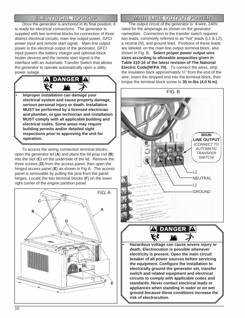
Once the generator is anchored in its final position, itis ready for electrical connections. The generator issupplied with two terminal blocks for connection of threedistinct electrical circuits; main line output power, GFCIpower input and remote start signal. Main line outputpower is the electrical output of the generator, GFCIinput powers the battery charger and optional blockheater devices and the remote start signal is theinterface with an Automatic Transfer Switch that allowsthe generator to operate automatically upon a utilitypower outage.
To access the wiring connection terminal blocks,open the generator lid (A) and place the lid prop rod (B)into the slot (C) on the underside of the lid. Remove thethree screws (D) from the access panel, then open thehinged access panel (E) as shown in Fig A. The accesspanel is removable by pulling the pins from the panelhinges. Locate the two terminal blocks (F) on the lowerright corner of the engine partition panel.
The output circuit of the generator is 4-wire, 240V,rated for the amperage as shown on the generatornameplate. Connection to the transfer switch requirestwo leads, commonly referred to as "hot" leads (L1 & L2),a neutral (N), and ground lead. Positions of these leadsare labeled on the main line output terminal block, alsoshown in Fig. B. Select proper power output wiresizes according to allowable ampacities given inTable 310-16 of the latest revision of The NationalElectric Code(NFPA 70). To connect the wires, stripthe insulation back approximately ½" from the end of thewire, insert the stripped end into the terminal block, thentorque the terminal block screw to 35 in-lbs (4.0 N-m).
EEEELLLLEEEECCCCTTTTRRRRIIIICCCCAAAALLLL HHHHOOOOOOOOKKKKUUUUPPPP
DDAANNGGEERR
• Improper installation can damage your electrical system and cause property damage, serious personal injury or death. Installation MUST be performed by a licensed electrician and plumber, or gas technician and installation MUST comply with all applicable building and electrical codes. Some areas may require building permits and/or detailed sight inspections prior to approving the unit for operation.
MMMMAAAAIIIINNNN LLLLIIIINNNNEEEE OOOOUUUUTTTTPPPPUUUUTTTT PPPPOOOOWWWWEEEERRRR
FIG. A
FIG. B
L2NEUTRALL1GROUND
MAINLINE OUTPUT(CONNECT TOAUTOMATICTRANSFER
SWITCH)
DDAANNGGEERR
• Hazardous voltage can cause severe injury or death. Electrocution is possible whenever electricity is present. Open the main circuit breaker of all power sources before servicing the equipment. Configure the installation to electrically ground the generator set, transfer switch and related equipment and electrical circuits to comply with applicable codes and standards. Never contact electrical leads or appliances when standing in water or on wet ground because these conditions increase the risk of electrocution.

11
A ground fault circuit interrupting (GFCI) receptacleis provided with the generator to power the batterycharger for reliable starting. It is also intended to poweran optional block heater if that option is desired.Connection of this circuit to a power supply that is only present when normal utility power is supplied isrecommended. By connecting the GFCI in this fashion,it is possible to insure that neither the battery charger orblock heater are on while the engine is running.Precautions are engineered into the generator to preventthese occurances but connection of the circuit in thisfashion provides an additional fail-safe method of engineand battery protection.
Input to the GFCI circuit is 3-wire, 120V, 15A.Connections include a "hot" lead (L1), neutral (N) andground lead. Positions of the incoming wire connectionsare labeled at the auxiliary connection block, shown inFig.C. Select proper GFCI supply wire sizeaccording to allowable ampacities given in Table310-16 of the latest revision of The National ElectricCode(NFPA 70). To connect the wires, strip theinsulation back approximately ¼" from the end of thewire, insert the stripped end under the screw and washeron the terminal block, then torque the terminal blockscrew to 20 in-lbs (2.3 N-m).
When the control panel mode switch is placed in theAUTO position, generator starting and stopping iscontrolled by the opening or closing of a set of voltagefree contacts. Two wires from those contacts areconnected to the generator through the auxiliaryconnection block shown in Fig. D. Use of a twisted pair ofstranded copper wire no smaller than AWG 18 gage isrecommended. To insure proper operation of the autostart feature, use a transfer switch offering “close-to-runcontrol contacts. To connect the wires, strip theinsulation back approximately ¼" from the end of thewire, insert the stripped end under the screw and washeron the terminal block, then torque the terminal blockscrew to 20 in-lbs (2.3 N-m).
GGGGEEEENNNNEEEERRRRAAAATTTTOOOORRRR SSSSTTTTAAAARRRRTTTT SSSSIIIIGGGGNNNNAAAALLLL
FIG. C
GGGGFFFFCCCCIIII CCCCIIIIRRRRCCCCUUUUIIIITTTT SSSSUUUUPPPPPPPPLLLLYYYY
FIG. D
NEUTRAL
L1
GFCICIRCUITSUPPLY
(CONNECT TO120V UTILITY
POWER)
ATS1
ATS2
GENERATORSTART SIGNAL
(CONNECT TOAUTOMATICTRANSFER
SWITCH)

12
1122KKWW WWIIRRIINNGG DDIIAAGGRRAAMM ((CCPP220000 CCOONNTTRROOLLLLEERR))
RE
LAY
PIN
WIR
E N
UM
BE
R30
185
1386
987
13
RELA
Y W
IRIN
G IN
FORM
ATIO
NW
IRE
NO.
WIR
E NA
ME/
DES
CRI
PTIO
NW
IRE
NO.
WIR
E NA
ME/
DES
CRI
PTIO
NW
IRE
NO.
WIR
E NA
ME/
DES
CRI
PTIO
NW
IRE
NO.
WIR
E NA
ME/
DES
CRI
PTIO
N1
BATT
ERY
PO
SITI
VE
11IG
NITI
ON
TIM
ING
INPU
T21
NOT
ASS
IGNE
D31
NOT
ASS
IGNE
D2
SWIT
CHED
BA
TTER
Y P
OSI
TIV
E12
REM
OTE
STA
RT +
22HI
GH
TEM
PERA
TURE
SEN
DER
3212
0V U
TILI
TY H
OT
3G
ENER
ATO
R G
ROUN
D13
STA
RTER
SHI
FT S
IGNA
L23
ALA
RM S
WIT
CH G
ROUN
D33
120V
UTI
LITY
NEU
TRA
L4
CONT
ROLL
ER S
TART
SIG
NAL
14M
ODE
SW
ITCH
AUT
O24
LOW
OIL
SEN
DER
34CT
15
GEN
ERA
TOR
LINE
115
MO
DE S
WIT
CH R
UN25
NOT
ASS
IGNE
D35
CT 1
CO
MM
ON
6G
ENER
ATO
R LI
NE 2
16M
ODE
SW
ITCH
CO
MM
ON
26NO
T A
SSIG
NED
36CT
27
GEN
ERA
TOR
LIN
E 3
17LE
D TE
ST27
NOT
ASS
IGNE
D37
CT 2
CO
MM
ON
8G
ENER
ATO
R NE
UTRA
L18
NOT
ASS
IGNE
D28
NOT
ASS
IGNE
D38
CT 3
9
BATT
ERY
GRO
UND
19NO
T A
SSIG
NED
29NO
T A
SSIG
NED
39CT
3 C
OM
MO
N10
IGNI
TIO
N SP
ARK
SIG
NAL
20NO
T A
SSIG
NED
30NO
T A
SSIG
NED
WIR
E NU
MBE
R LE
GEN
D

13
The engine driving the generator is engineered toprovide reliable power on either Liquefied Propane Vapor(LPG) or Natural Gas. For proper operation on thesefuels, it is important to deliver gas with adequate energycontent, at sufficient pressure and flow rate. This isdesigned to operate on Liquefied Propane Vapor (LPG)with a minimum energy content of 2500 BTU per cubicfoot or Natural Gas with a minimum energy content of1000 BTU per cubic foot. This generator is designed tooperate with a fuel pressure at the inlet of the unitbetween 7 and 11 inches of water column (4-6ounces).
Required fuel flow rates for specific models are givenin the table below. To insure correct sizing of the pipingsupplying fuel to the generator set, provide the flow andpressure requirements of this section to a fuel supplier orlicensed plumber during the installation planning stage. Ifthe fuel supplier cannot guarantee delivery of fuel withthese properties, the generator may not perform asadvertised.
Due to differences in the energy content of fuel used,it is necessary to derate the output of the generator whenconnected to Natural Gas. Additionally, regional and/orseasonal variations in the makeup of the fuel can furtheraffect output of the engine/generator system. Whenusing Natural Gas fuel with minimum properties asdefined, engine output can fall approximately 10% belowthat of the same set using Propane Vapor.
FFFFUUUUEEEELLLL SSSSPPPPEEEECCCCIIIIFFFFIIIICCCCAAAATTTTIIIIOOOONNNNSSSS AAAANNNNDDDDCCCCOOOONNNNSSSSUUUUMMMMPPPPTTTTIIIIOOOONNNN RRRREEEEQQQQUUUUIIIIRRRREEEEMMMMEEEENNNNTTTTSSSS
WWAARRNNIINNGG
• Natural gas (NG) is highly explosive.• Natural gas (NG) is lighter than air and collects
in high places.• Liquid propane vapor (LPG) is highly explosive.• Liquid propane vapor (LPG) is heavier than air
and collects in lower places.• Extreme caution should be taken when working
on a new installation or while performing general maintenance.
• Do not smoke when near the unit.• Keep flames, sparks, pilot lights, arc-producing
equipment, switches and all other sources of ignition well away. Keep a type ABC fire extinguisher handy.
• Potential for fire or explosion always exist whenusing natural gas (NG) or liquid propane vapor (LPG) as a fuel source. Install this unit in compliance with all local fuel codes.
• Do Not operate engine if smell of fuel is present or other explosive conditions exist.
Per the National Gas Code (NFPA 54 - ANSI2223.1), a manual shutoff valve in the fuel supply lineto the generator is recommended.
LP Vapor(ft 3/hr)
LP Vapor(Gal/hr)
Natural Gas(ft 3/hr)
PM401211 81 2.2 186PM409011 79 2.1 176
DDAANNGGEERR
• All fuel system installations MUST BE done by alicensed plumber or licensed gas technician and must comply with all applicable codes, standards and regulations.
FUEL CONSUMPTION TABLE
All values reflect consumption at 100% rated output.

14
After electrical connections are complete, the nextinstallation step is to connect a fuel supply to the unit.The fuel inlet fitting supplied with the generator is male½" NPT and is located adjacent to a fuel access hole inthe lower engine end panel as illustrated in Fig E. Toaccommodate potential settling of the generator relativeto rigid supply pipeline, use of a flexible line to make thefinal connection in the supply line is suggested. Whenmaking flexible connections, use only materials rated forthe fuel supplied and approved for use by local, regionalor national codes and/or regulatory agencies.
When supplying natural gas as the operating fuel,provide fuel with a minimum of 1000 BTU/ft3 at inletpressures between 7" and 11" of water column (4 - 6oz). Failure to meet these minimums will cause thegenerator to run poorly and/or may limit output to valuesbelow nameplate value. If fuel with these qualities is notavailable, a low calorific fuel system kit may be required,at additional cost. Contact the customer service centerto determine if a kit is required in cases of inadequatefuel quality.
Refer to the Fuel Consumption Table on page 13 forfuel flow requirements for the unit installed. Size allfeeding piping to deliver sufficient flow above theminimum pressure of 7" water column (4 oz).
Per the National Gas Code (NFPA 54 - ANSI2223.1), a manual shutoff valve in the fuel supply lineto the generator is recommended.
Once all external connections are complete, checkthe position of the flexible engine supply hose, as shownin Fig F. When configuring a generator to run on aspecific fuel, it is necessary to verify correct positioningof the hose on the fuel pressure regulator outlet. Thefactory default position is for natural gas (NG), asindicated in Fig F. If the fuel hose is not in the properposition, move it to the tee branch labeled NG, makingsure the brass cap is placed securely on the oppositebranch. With fuel supply attached and the flexible enginesupply hose on the proper branch of the regulator output,the fuel hookup is complete. The generator is suppliedwith a fixed orifice tuned to provide proper fuel flow andno further adjustment of the fuel system is possible orrequired.
FFFFUUUUEEEELLLL HHHHOOOOOOOOKKKKUUUUPPPP Natural Gas (NG)
FIG. E
DDAANNGGEERR
• All fuel system installations MUST BE done by alicensed plumber or licensed gas technician and must comply with all applicable codes, standards and regulations.
WWAARRNNIINNGG
• Natural Gas and Propane Vapor are highly explosive gases. Check ALL fuel system connections for leaks before starting engine/generator set.
• DO NOT use a flame to check for leaks.• Use approved equipment and methods to check
for leaks.

15
In cases where liquefied propane vapor is selectedas the fuel of choice, insure fuel delivery in the gaseousstate, with a minimum energy content of 2500 BTU/ft3,at inlet pressures between 7" and 11" of watercolumn (4 - 6 oz). Fuel below these specifications maycause improper engine operation and/or failure to deliverrated generator output. Size all fuel system plumbing toprovide fuel flow as given in the Fuel ConsumptionTable on page 13, at a minimum pressure of 7" watercolumn (4 oz).
After completing external supply connections, verifyproper positioning of the flexible engine supply hose onthe fuel pressure regulator output, as shown in Fig F.The factory default position is for natural gas (NG),requiring a change for liquefied propane vapor (LPG)operation. If the fuel hose is not in the proper position,move it to the tee branch labeled LPG, making sure thebrass cap is placed securely on the opposite branch.With fuel supply attached and the flexible engine supplyhose on the proper branch of the regulator output, thefuel hookup is complete. The generator is supplied witha fixed orifice tuned to provide proper fuel flow and nofurther adjustment of the fuel system is possible orrequired.
Propane Vapor (LPG)
FIG. F

16
To insure reliable starting in most weatherconditions, it is important to properly match a battery tothe requirements of the generator. The generator uses a12 Volt, direct current, negative ground control systempowered by an automotive style lead acid battery.Successful engine starting is dependent upon thecranking speed of the engine, which in turn is affected bythe cranking capacity of the battery. When selecting abattery, choose the model that provides the highestavailable cold cranking amperes (CCA) within a givensize range, as specified by the Battery CouncilInternational (BCI). The battery tray and cables suppliedwith the generator are sized to accept either a BCIGroup 26 or 26R battery, with a minimumrecommended rating of 450 CCA.
The next step in installation of the generator isplacement and connection of the engine crankingbattery. Provided battery cables and battery rack aresized to accept a BCI Group 26 or 26R automotive stylebattery. A battery with a minimum of 450 CCA (coldcranking amperes) in this size range is recommended toassure reliable engine starting.The electrolyte is a dilute sulfuric acid that is
harmful to the skin and eyes. It is electricallyconductive and corrosive. The followingprocedures are to be observed.
• Wear full eye protection and protective clothing.
• Where electrolyte contacts the skin, wash itoff immediately with water.
• Where electrolyte contacts the eyes, flush thoroughly and immediately with water and seek medical attention.
• Spilled electrolyte is to be washed down with and acid neutralizing agent. A common practice is to use a solution of one pound (500 grams) bicarbonate of sodato one gallon (4 liters) of water. The bicarbonate of soda solution is to be addeduntil the evidence of reaction (foaming) hasceased. The resulting liquid is to be flushedwith water and the area dried.
A battery presents a risk of electrical shock and ahigh short circuit current. The followingprecautions are to be observed when working onbatteries:
• Remove watches, rings or other metal objects.
• Use tools with insulated handles.• Wear rubber gloves.• Do not lay tools or metal parts on top of
batteries.• Disconnect charging source prior to
connecting or disconnecting battery terminals.
• Determine if the battery is inadvertently grounded. When inadvertently grounded, remove source of ground. Contact with any part of a grounded battery is capable of resulting in electrical shock. The risk of such shock is reduced when such grounds are removed during installation and maintenance.
• Failure to connect and disconnect in the proper sequence can cause equipment damage. Ensure there is a clean tight fit from the cables to the post.
WWAARRNNIINNGG
CCAAUUTTIIOONN
WWAARRNNIINNGG
Lead-acid batteries present a risk of fire becauselead-acid batteries generate flammable hydrogengas.
• Do not smoke when near batteries.• Do not cause flame or spark in battery area.• Discharge static electricity from body
before touching batteries by first touching agrounded metal surface.
• Do not dispose of batteries in a fire. The battery is capable of exploding.
• Do not open or mutilate the battery or batteries. Released electrolyte has been known to be harmful to the skin and eyes and to be toxic.
BBBBAAAATTTTTTTTEEEERRRRYYYY RRRREEEEQQQQUUUUIIIIRRRREEEEMMMMEEEENNNNTTTTSSSS
BBBBAAAATTTTTTTTEEEERRRRYYYY PPPPLLLLAAAACCCCEEEEMMMMEEEENNNNTTTT AAAANNNNDDDDCCCCOOOONNNNNNNNEEEECCCCTTTTIIIIOOOONNNN
WWAARRNNIINNGG
• Make sure the control panel Mode switch is in the OFF position before connecting the battery cables. Failure to do so may result in unexpected engine starting and to personal injury.

17
To install the battery, begin by placing the battery (A)into the battery rack as shown in Fig G. Orientation ofthe battery terminals is according to installer preferenceas the supplied battery cables are of adequate length toreach terminals regardless of battery direction. Securethe battery to the rack using the J-bolts (B), nuts (C) andbattery strap (D) packed in the literature bag packed withthe unit, as illustrated by Fig G.
After the battery is tight in the rack, begin attachingthe battery cables to the battery posts, starting with thepositive (+), or red, cable (E). Loosen the bolt (F) on thepost clamp slightly to allow the clamp to expand, thenfirmly push the clamp onto the battery post markedpositive (+) until the top of the post extends past the topof the clamp. Rotate the clamp around the post asrequired to insure the clamp cannot contact any metalcomponents, then tighten the clamp bolt (F) until snug.Finally,slide the post boot (G) down the cable and placeit entirely over the clamp.
Finish connecting the battery by placing the negative(-), or black, battery cable (H) to the battery post markednegative (-). Push the clamp firmly over the post until thepost extends past the top of the clamp, then rotate theclamp to avoid contact with any metal parts. Tighten thebattery clamp bolt (I) until snug.
The final step of battery installation is to verify properconnection of all battery charger connections. A batterycharging system (J) is included with the engine/generatorset to maintain the battery charge during extendedperiods of generator inactivity, therefore providingconsistent starting. A quick check of chargerconnections will verify that factory connections arecorrect so the charger can function as intended. Insure
that the charger is connected by checking to see that it isplugged into a powered GFCI receptacle, and that thepositive (+) and negative (-) charger cables areconnected to their respective battery cables.
Once all connections are made, the final installationstep is verification of proper engine oil level. The engineis factory filled and shipped with approximately 1.5 qt(1.4 liters) of SAE 5W-30 weight oil. Begin the levelcheck by removing the dipstick (K), wiping it clean, thenreinserting it into the engine. Remove the dipstick asecond time, checking that the oil level falls between theupper and lower limit marks (see Fig A ,page 26) on theend of the dipstick. Adjust engine oil level as required sothe level is at the upper limit mark on the dipstick, addingoil to the engine through the oil fill cap (L) as shown inFig H.
BBBBAAAATTTTTTTTEEEERRRRYYYY PPPPLLLLAAAACCCCEEEEMMMMEEEENNNNTTTT AAAANNNNDDDDCCCCOOOONNNNNNNNEEEECCCCTTTTIIIIOOOONNNN ((((ccccoooonnnntttt .... ))))
LLLLUUUUBBBBRRRRIIIICCCCAAAATTTTIIIIOOOONNNN
FIG. G
FIG. H
• State and federal agencies have determined that contact with used engine oil can cause cancer or reproductive toxicity. Take care to limit skin contact and breathing of vapors as much as possible. Use rubber gloves and washexposed skin.
WWAARRNNIINNGG
• Any attempt to crank or start the engine before it has been properly serviced with the recommended oil will result in an engine failurethat is not covered by warranty.
CCAAUUTTIIOONN
L
K

18
After completing all installation procedures, read andunderstand the operating instructions for the generatorcontroller. Know how the control panel operates, what toexpect when activating control panel switches and howto shut the generator off in the event of an emergency.Before starting the generator for the first time, check offall items on the following list, then follow the givenprocedure to verify correct operation of the generator. Is unit level? Is adequate free air space (3 feet minimum)
available on all sides of the enclosure? Are all cabinet openings free from blockage? Is the exhaust directed away from dwellings, dwelling
air intakes, or combustible materials? Are the fuel supply lines and internal generator fuel
connections leak-free? Is fuel supply pressure within specifications? Is the regulator connection properly configured for
the fuel supplied? Is an approved transfer switch used to prevent
backfeed into utility lines? Are electrical connections tight, and properly
connected? Are electrical conductors sized properly? Is the engine filled to the proper level with the correct
type of oil? Is a properly sized engine cranking battery correctly
installed? Is the battery maintenance charger plugged in and
operating correctly? Are all protective covers installed and tightened? Are all tools clear of moving or electrically live parts? Is the installation inspected and approved as
required by local or regional code? Once all items on the checklist are marked off,
complete the initial startup using the listed steps.
1. Place the control panel mode switch on the generator in the OFF position.
2. Move the main line circuit breaker handle on the generator to the OFF position.
3. Check the utility power supply to the transfer switch following the instructions provided by the switch manufacturer.
4. Ensure utility power to the transfer switch is shut off.
5. Return to the generator and open any manual shutoffvalves in the fuel supply system.
6. Move the control panel mode switch to the RUN position. The generator should crank and start.
7. Allow the generator to run for approximately three (3)minutes, then move the main line circuit breaker handle to the ON position.
8. Check across the terminals of the main line power output block (Red to Black) for proper frequency and voltage. Frequency should read approximately 62.5 Hz and voltage between 240 and 245 volts at no loadconditions.
9. Adjust no load speed as required to meet approximately 62.5 Hz.
10. Shut the generator down by moving the mode switch back to the OFF position.
11. Restore utility power to the transfer switch.12. Place the control panel mode switch on the
generator set in the AUTO position.13. Perform a manual exercise cycle following the
instructions provided by the switch manufacturer. If wiring is connected properly to the switch, the generator will start and stop under switch control. While the generator is running, check the voltage and frequency across the emergency supply terminals on the transfer switch. Values should match those found in Steps 8 and 9.
14. Allow the transfer switch to shut the generator off by letting it complete the manual exercise cycle.
15. With the generator mode switch still in the AUTO position, simulate utility power failure by switching utility power to the transfer switch OFF. Verify correct function of the automatic transfer switch as indicated in the switch manual. Restore utility power to the transfer switch and verify correct automatic transfer switch function. Allow the switch to shut the generator down.
16. Inspect the site to ensure no packaging or installationmaterials remain within or against the generator.
17. Replace all covers on the generator.18. Place the generator into service by moving the
mode switch to the AUTO position.
FFFFIIIIRRRRSSSSTTTT TTTTIIIIMMMMEEEE SSSSTTTTAAAARRRRTTTTUUUUPPPP
• Failure to set the controller to AUTO before leaving the generator renders the generator unavailable for automatic standby service.
CCAAUUTTIIOONN
• Contact with high voltages present in generators and utility systems can cause severe electric shock or death. Avoid contact with all live components.
• Allow only qualified generator service technicians or licensed electricians to perform initial system start-up.
DDAANNGGEERR
• Generator is now supplying dangerous voltages. Use extreme caution performing electrical checks.
DDAANNGGEERR

19
GGGGEEEENNNNEEEERRRRAAAATTTTOOOORRRR SSSSPPPPEEEECCCCIIIIFFFFIIIICCCCAAAATTTTIIIIOOOONNNNSSSS
EEEENNNNGGGGIIIINNNNEEEE SSSSPPPPEEEECCCCIIIIFFFFIIIICCCCAAAATTTTIIIIOOOONNNNSSSS
PM401211 PM400911Rated Output
Propane Vapor 11 kW 9.5 kWNatural Gas 9.9 kW 8.5 kW
Rated AmperagePropane Vapor 45.8 A 39.6 ANatural Gas 41.3 A 35.4 A
Rated Voltage 240 V 240 VFrequency 60 Hz 60 Hz Phase Single SingleCircuit Breaker Size 50 Amp 45 Amp
Rated Operating Temperature-20°F to 104°F (-29°C to
40°C)-20°F to 104°F (-29°C to
40°C)Cooling Airflow 977 ft3/min 977 ft3/minFull Load Sound Level 68 dB(A)* 68 dB(A)*Overall Dimensions 42 1/2 in x 32 in x 27 in 42 1/2 in x 32 in x 27 inWeight 478 lb 476 lb
PM401211 PM400911Manufacturer Honda HondaManufacturer Engine Model VXC-GDACM VXC-GDADM
StyleAir cooled, V-twin, 2-
cylinderAir cooled, V-twin, 2-
cylinderBlock Aluminum AluminumDisplacement 670 cc (40.9 in3) 614 cc (37.5 in3)Bore 3.0 in (77 mm) 3.0 in (77 mm)Stroke 2.8 in (72 mm) 2.6 in (66 mm)Compression Ratio 8.3:1 8.3:1Exhaust Flow 102 ft3/min 93 ft3/minExhaust Temperature 1007 oF 1007 oFOil capacity
without filter 1.2 US qt (1.1 l ) 1.2 US qt (1.1 l )with filter 1.5 US qt (1.4 l ) 1.5 US qt (1.4 l )
Oil Filter Honda # 15400-P0H-305PE Honda # 15400-P0H-305PEAir Filter (paper element) Honda # 17210-ZJ1-841 Honda # 17210-ZJ1-841
Spark plugsNGK # ZGR5A or Denso # J16CR-U
NGK # ZGR5A or Denso # J16CR-U
Spark plug gap0.12 - 0.16 in
(0.30 – 0.40 mm)0.12 - 0.16 in
(0.30 – 0.40 mm)Valve Clearance
Intake0.005 - 0.007 in (0.13 - 0.17 mm)
0.005 - 0.007 in (0.13 - 0.17 mm)
Exhaust0.007 - 0.009 in (0.18 - 0.22 mm)
0.007 - 0.009 in (0.18 - 0.22 mm)
* Average @ 7 m

20
EEEELLLLEEEECCCCTTTTRRRRIIIICCCCAAAALLLL SSSSPPPPEEEECCCCIIIIFFFFIIIICCCCAAAATTTTIIIIOOOONNNNSSSS
FFFFUUUUEEEELLLL SSSSPPPPEEEECCCCIIIIFFFFIIIICCCCAAAATTTTIIIIOOOONNNNSSSS
PM401211 PM400911Style 2 pole, brushless 2 pole, brushlessSynchronous Speed 3600 RPM 3600 RPMExcitation Self regulated Self regulatedMotor Starting Capacity 12 sKVA† 12 sKVA†
Winding ResistancesStator 0.30 – 0.50 Ω 0.30 – 0.50 ΩExcitation 1.4 – 1.6 Ω 1.4 – 1.6 ΩRotor 5.9 – 6.0 Ω 5.9 – 6.0 Ω
Capacitors 40µF, 500V 40µF, 500V
PM401211 PM400911
Battery 12 VDC, BCI Group 26 or 26R 12 VDC, BCI Group 26 or 26RMinimum CCA 450 450Maintenance charger 6 Amp, 3 stage 6 Amp, 3 stage
Fuse 14 Amp, 32 VDC, Type SFE 14 Amp, 32 VDC, Type SFEEngine Alternator 10 Amp regulated 10 Amp regulated
Fuse 25 Amp, 32 VDC, Type 3AG 25 Amp, 32 VDC, Type 3AGFuel Solenoids
Opening Voltage 9.5 VDC 9.5 VDCCoil Resistance 29.1 - 29.8 Ω 29.1 - 29.8 Ω
Oil Pressure Switch 14 psi 14 psiNormally open, close on rise Normally open, close on rise
High Temp Switch285°F, Normally open, close
on rise285°F, Normally open, close
on rise
PM401211 PM400911Fuel Pressure 7 – 11 inches water (4 – 6 oz) 7 – 11 inches water (4 – 6 oz)Fuel Consumption(100% load)
Propane Vapor 81 ft3/hr (2.2 Gal/hr) 79 ft3/hr (2.1 Gal/hr)Natural Gas 186 ft3/hr 176 ft3/hr
Min Energy ContentPropane Vapor 2500 BTU/ft3 2500 BTU/ft3
Natural Gas 1000 BTU/ft3 1000 BTU/ft3
AAAALLLLTTTTEEEERRRRNNNNAAAATTTTOOOORRRR SSSSPPPPEEEECCCCIIIIFFFFIIIICCCCAAAATTTTIIIIOOOONNNNSSSS
† Measured @ 30% instantaneous voltage dip
21
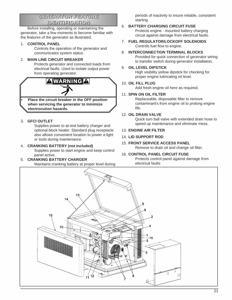
Before installing, operating or maintaining thegenerator, take a few moments to become familiar withthe features of the generator as illustrated.
1. CONTROL PANELControls the operation of the generator and communicates system status.
2. MAIN LINE CIRCUIT BREAKERProtects generator and connected loads from electrical faults. Used to isolate output power from operating generator.
3. GFCI OUTLETSupplies power to at-rest battery charger and optional block heater. Standard plug receptacle also allows convenient location to power a light or tools during maintenance.
4. CRANKING BATTERY (not included)Supplies power to start engine and keep control panel active.
5. CRANKING BATTERY CHARGERMaintains cranking battery at proper level during
periods of inactivity to insure reliable, consistent starting.
6. BATTERY CHARGING CIRCUIT FUSEProtects engine - mounted battery charging circuit against damage from electrical faults.
7. FUEL REGULATOR/LOCKOFF SOLENOIDSControls fuel flow to engine.
8. INTERCONNECTION TERMINAL BLOCKSProvided for quick connection of generator wiringto transfer switch during generator installation.
9. OIL LEVEL DIPSTICKHigh visibility yellow dipstick for checking for proper engine lubricating oil level.
10. OIL FILL PLUGAdd fresh engine oil here as required.
11. SPIN ON OIL FILTERReplaceable, disposable filter to remove contaminant's from engine oil to prolong engine life.
12. OIL DRAIN VALVEQuick turn ball valve with extended drain hose to speed up maintenance and eliminate mess.
13. ENGINE AIR FILTER14. LID SUPPORT ROD15. FRONT SERVICE ACCESS PANEL
Remove to drain oil and change oil filter.
16. CONTROL PANEL CIRCUIT FUSEProtects control panel against damage from electrical faults
GGGGEEEENNNNEEEERRRRAAAATTTTOOOORRRR FFFFEEEEAAAATTTTUUUURRRREEEEIIIIDDDDEEEENNNNTTTTIIIIFFFFIIIICCCCAAAATTTTIIIIOOOONNNN
WWAARRNNIINNGG
• Place the circuit breaker in the OFF position when servicing the generator to minimize electrocution hazards.

22
A standby generator is an engine driven air cooledsystem to convert the energy contained in either liquidpropane vapor or natural gas to electrical power. Whencoupled with an automatic transfer switch to monitor forfailure of utility power, the unattended system can start,stop and transfer between sources to insure a nearlyseamless supply of power. The generator is housed in aweather resistant, sound attenuated enclosure foroutdoor installation only.
Before installing and starting the generator, becomefamiliar with the controls and operational features of thegenerator. Know how the control panel operates, what toexpect when activating control panel switches and howto shut the generator off in the event of an emergency.
A. MODE SWITCHB. CIRCUIT BREAKERC. STATUS INDICATOR LIGHTSD. HOUR METERE. LAMP TEST SWITCH
A. Mode Switch
The Mode switch is used to set the operating state ofthe generator. Placing the switch in the OFF positionprevents engine operation or stops the engine if it isalready running. Moving the switch to the RUN positionimmediately starts the generator. Putting the switch in
the AUTO position sets the generator for unattendedoperation under the control of a properly matchedautomatic transfer switch.
B. Main Line Circuit Breaker
A Main Line Circuit Breaker is provided to protect thegenerator from damage caused by electrical faults withinthe attached electrical distribution system. It is also usedto isolate the output of the generator from the connectedelectrical distribution system by moving the breakerhandle to the OFF position. Placing the breaker in thisposition does not prevent startup of the generator.
C. Status Indicator Lights
Status indicator lights are provided to communicatethe status of the generator to the user. Under normalrunning conditions, only the green Generator On light islit. Function of all other lights are described on page 24.
D. Generator Hour Meter
The Generator Hour Meter is provided to track thetotal numbers of hours of operation. The hour meterruns whenever the engine is running and the alternator isproducing electricity. Placing the main line circuitbreaker in the OFF position while the engine is runningdoes not stop the meter from counting hours.
E. Lamp Test Switch
A lamp test switch is provided to check for function ofall indicator lights. Press the lamp test switch while theengine is at rest, with the control panel mode switch inthe OFF position to illuminate all status lights.
F. Engine Charging Circuit Fuse
The Engine Charging Circuit Fuse providesprotection to the engine mounted alternator in the eventof electrical faults in the positive (+) battery circuit.Failure of this fuse prevents charge from reaching thebattery when the generator is running, leading to earlybattery failure. Replace the fuse only with an equivalentsize and style of fuse to prevent damage to the generatorelectrical control system.
GGGGEEEENNNNEEEERRRRAAAATTTTOOOORRRR OOOOPPPPEEEERRRRAAAATTTTIIIIOOOONNNN
CCCCOOOONNNNTTTTRRRROOOOLLLL PPPPAAAANNNNEEEELLLL FFFFEEEEAAAATTTTUUUURRRREEEESSSS
C
D
E
A
B
CCCCOOOONNNNTTTTRRRROOOOLLLL PPPPAAAANNNNEEEELLLL SSSSWWWWIIIITTTTCCCCHHHHEEEESSSS
23
Two methods are available to start the generator.The automatic, or AUTO mode is for use with anautomatic transfer switch. With the control panel modeswitch set to this position, the generator waits for anexternal signal to start. This signal is supplied by thetransfer switch when utility power is of unacceptablequality. Since utility power can fail at any time, be awarethe generator can start unexpectedly whenever in theAUTO position. Keep away from moving parts at alltimes. Once utility power is once again acceptable, thesignal from the transfer switch is removed, the generatorshuts off, then returns to waiting for another signal tostart.
The other method for starting the generating is toplace the mode switch into the RUN position. This modeis intended for generator control during maintenance or ifan automatic transfer switch is not used. With the controlpanel switch shifted to this position, the generator willimmediately attempt to start after a brief pause. Uponstarting, the generator runs until the switch is movedfrom the RUN position, at which time the generator willshut off.
To insure the generator starts without damaging thestarter motor, cranking of the engine is performed in acyclic manner. When the generator is started from eitherthe AUTO or RUN positions, the controller alternatesbetween 10 seconds of engine cranking, followed by 10seconds of engine rest. If the engine starts during any ofthe cranking periods, crank attempts are halted and thecontroller begins monitoring for proper function of thegenerator. In the event that three 10 second startattempts occur without the engine starting, crankingattempts are halted and the Overcrank light is lit.
After the engine is started and the generator isproducing electrical power, the controller beginsoperation in a monitoring state. In this state, severalgenerator functions are continuously checked to ensureproper operation of the generator. If functions aredetermined unacceptable, a fault is declared, the engineis shut down and a status light is lit to communicate thereason for the shutdown.
When operating with the control panel switch in theRUN position, the generator will continue to run until a
fault is declared or until the mode switch is moved to theOFF position. Once the switch is shifted to the OFFposition, the engine is shut off.
When operating with the control panel switch in theAUTO position, the generator continues to run until afault light is declared or the run signal is removed. Oncethe signal is removed, the engine shuts down and thecontroller returns to waiting for a start signal.
SSSSTTTTAAAARRRRTTTTIIIINNNNGGGG TTTTHHHHEEEE GGGGEEEENNNNEEEERRRRAAAATTTTOOOORRRR
CCCCYYYYCCCCLLLLIIIICCCC CCCCRRRRAAAANNNNKKKK
WWAARRNNIINNGG
• With the Mode switch in the Auto position, the unit starts and stops without notice.
• Keep clear of all moving parts at all times.
RRRRUUUUNNNN SSSSTTTTAAAATTTTEEEE
SSSSHHHHUUUUTTTTDDDDOOOOWWWWNNNN

24
Status indicator lights relay conditions of generatorfunction for user or service technician convenience.Illumination of these indicator lights communicateconditions that require generator service but are notsevere enough to cause damage if the generator isallowed to operate. Contact a qualified service technicianimmediately for service if any of the listed lights are lit,even if the generator appears to function normally.
A. LOW BATTERYThe Low Battery light is lit when the cranking battery voltage falls below 11.0 volts. At this level, the battery begins to lose the ability to consistently start the engine. Causes of low battery voltage may include a failing battery, failed battery charger or failed engine alternator.
B. NOT IN AUTO
The Not In Auto light is lit whenever the control panel mode switch is not placed in the AUTO position. This light is provided to call attention to this condition since the generator cannot start automatically during a power outage without the switch in the AUTO position. It is normal for this lamp to light when the generator is running with the mode switch in the RUN position, or if the switch is in the OFF position. To turn the light off,move the mode switch to the AUTO position.
H. GENERATOR ON
The Generator On light illuminates when the generators engine is running. This is the only light lit when the generator is supplying power asintended.
Fault lights relay conditions that may cause damageto the generator and/or loads connected to the output ofthe generator. When any of the listed situations occurwhile the generator is running, the generator is shutdown and the fault light associated with the shutdowncause is lit. Once the light is lit, it remains on until it iscleared by moving the control panel mode switch to theOFF position. If a fault light is lit, determine and correctthe cause of the problem before restarting the generator.During generator starting, the controller ignores faultconditions until 15 seconds after the generator starts,then uncleared faults will once again cause the generatorto shut off. To determine possible fault causes, refer tothe troubleshooting section of this manual or contact aqualified service technician for assistance.
C. OVERCRANK
The Overcrank light is lit if all three 10 second cyclic crank attempts are unsuccessful in starting
the engine. Once the light is on, the generator does not attempt to start until the fault is reset. When the Overcrank light is on , verify fuel is available at the inlet to the unit, then check the condition of the cranking battery.
D. LOW OIL
The Low Oil light turns on and the engine is shut off if the engine oil level falls too low. To avoid engine damage, engine oil pressure is monitoredto determine the amount of oil in the engine. When pressure falls below a preset level, a Low Oil fault occurs. Check for proper oil level if the generator shuts down due to a Low Oil alarm.
E. HIGH TEMPERATURE
The High Temperature light illuminates if the temperature of the engine becomes too high. Engine oil temperature is monitored while the engine is active and the engine is shut off to avoid damage if the oil temperature becomes toohigh. When operating the generator in temperatures above the maximum listed on the nameplate, it is necessary to reduce the load connected to the generator to avoid overheating. If high ambient temperatures or excessive loads are eliminated as possible causes of High Temperature shutdown, check to insure cabinet openings are not restricted by debris.
F. OVERSPEED
The Overspeed light is turned on if the generator engine is running too fast. Electrical output of thegenerator at high speeds may damage loads connected to the generator output and/or engine failure may occur at excessive speeds. If the generator shuts down on an Overspeed error, seek assistance from a qualified generator service technician.
G. UNDERSPEED
The Underspeed light is turned on if the generator engine is running too slow. Electrical output of the generator at low speeds can damage loads connected to the generator outputand/or generator failure may occur due to excessive heating in the generator head. If the generator turns off due to an Underspeed error, check to see that the connected loads do not exceed the nameplate rating of the generator.
SSSSTTTTAAAATTTTUUUUSSSS IIIINNNNDDDDIIIICCCCAAAATTTTOOOORRRRSSSS
FFFFAAAAUUUULLLLTTTTSSSS

25
1. Perform first change at 25 hours.
MMMMAAAAIIIINNNNTTTTEEEENNNNAAAANNNNCCCCEEEE
Every monthor 15 hours
Every 6 monthsor 100 hours
Every year or300 hours
Every 2 yearsor 500 hours
Engine Oil Check X
Change X 1
Engine Oil Filter Change X
Oil Cooler Check and Clean X
Engine Air Filter Check X
Change X
Battery Check and Clean X
Battery Charger Check X
Spark Arrestor Check and Clean X
Spark Plugs Check X
Replace X
Valve Clearance Check and Adjust X
Generator Output Frequency Check and Adjust X
Fuel System Check X
Cooling Air Openings Check X
To ensure reliable generator operation, it is critical toperiodically inspect all components. The following chartis provided as a guide for service check intervals. Whenthe generator is operated under excessively hot, or dustyconditions, shorten service intervals according to theseverity of the conditions encountered. To performperiodic inspections or maintenance, refer to the
procedures listed in the following sections. A qualifiedgenerator service technician should perform inspectionsor adjustments requiring specialized tools or training.Users unfamiliar with any of the listed procedures shouldcontact an authorized dealer for servicing assistance.
Maintenance Item

26
Prior to checking the oil level, start the generator bymoving the Mode switch on the control panel to the RUNposition. Allow the generator to run for one or twominutes, then shut it down by returning the switch to theOFF position. After the engine comes to a stop let theengine set for a couple of minutes before checking the oillevel. Begin the level check by removing the dipstick (A),wiping it clean, then reinserting it into the engine.Remove the dipstick a second time, checking that the oillevel falls between the upper and lower limit marks onthe end of the dipstick, as shown in Fig. A. Adjust engineoil level as required so the level is at the upper limit markon the dipstick, adding oil to the engine through the oil fillcap (B) as shown in Fig B. Add only oil of the samespecification as the oil already in the engine.
EEEENNNNGGGGIIIINNNNEEEE OOOOIIIILLLL LLLLEEEEVVVVEEEELLLL CCCCHHHHEEEECCCCKKKK
Fig. A
UPPER LIMIT
LOWER LIMIT
WWAARRNNIINNGG
• Before performing any maintenance, make sure the Mode switch is in the OFF position, the circuit breaker is in the OFF position and the positive (red) battery cable is disconnected.
• Generator/engine components are hot to the touch when operating. To prevent burns to the skin allow unit to cool before touching internal generator or engine components.
• Crankcase pressure can blow hot engine oil outthe fill opening causing severe burns. Always stop the generator before removing the oil fill cap.
• Keep hands, feet, clothing, etc., away from drivebelts, fans, and other moving or hot parts. Never remove any drive belt or fan guard while the unit is operating.
• Engine block heater can cause electrical shock. Remove engine block heater plug from electrical outlet before working on block heater connections.
• Improper service or replacement of parts can lead to severe personal injury or death and to damage to equipment and property. Service personnel must be qualified to perform electrical and mechanical service.
• Use caution when working on live electrical equipment. Remove jewelry, make sure clothingand shoes are dry and stand on a dry wooden platform.
• Do not smoke around the generator. Wipe up any fuel or oil spills immediately. Ensure that nocombustible materials are left in the generator compartment, or on or near the generator, as FIRE or EXPLOSION may result. Keep the area surrounding the generator clean and free from debris.
• When performing maintenance on this equipment, nothing should be done that might render the equipment or its installation in non-compliance with applicable codes, standards, and regulations.
• Eye protection should be used.
MMMMAAAAIIIINNNNTTTTEEEENNNNAAAANNNNCCCCEEEE ((((ccccoooonnnntttt .... ))))
B
A
Fig. B

27
Selection of the correct grade and type of engine oilgreatly affects the performance of the generator,especially when starting. Before selecting replacementoil for an oil change, consider the anticipated operatingconditions the generator may be exposed to. Choose theappropriate weight of oil for anticipated temperaturesfrom Chart C. If temperatures are expected to fluctuatebetween extremes prior to the next oil change interval,use of synthetic oil is recommended. Use of oil meeting aminimum American Petroleum Institute (API)classification of SJ is advised.
Engine oil changes are recommended at themaximum intervals given in the Periodic MaintenanceTable. When operating in hot or dusty conditions shorterchange intervals may be necessary. To change theengine oil and oil filter, the listed procedure isrecommended.
1. Warm up the engine oil by running a cold engine for a few minutes, then shutting it off. Start and stop theengine by moving the control panel mode switch between the RUN and OFF positions. Insure the mode switch is in the OFF position before continuing the oil change.
2. Place an oil drain pan capable of holding three (3) quarts under the end of the oil drain hose (A).
3. Remove the oil fill cap (B) and place in a convenient location. While holding the end of the oil drain hose (A) in the drain pan, slowly open the oil drain valve (C) by turning the handle clockwise until the valve isfully open. Allow the engine oil to completely drain into the drain pan.
4. When the engine oil is completely drained, close the valve (C) by turning the handle fully counterclockwise.
5. Place the drain pan underneath the spin on oil filter (D), then remove the filter by turning it counterclockwise. Once loose, drain all of the oil from the filter into the drain pan.
6. Apply a light film of oil to the gasket on the new oil filter, then screw the filter onto the adapter until the gasket lightly touches the adapter face. Tighten the filter an additional ¾ to 1 turn.
7. Refill the engine with 1.5 qt (1.4 liters) of new engine oil through the engine oil fill cap (B). Refer to the engine oil recommendations on chart C for the proper grade of oil. Replace the oil fill cap (B), then start the engine and check for leaks.
8. Stop the engine and check the engine oil level as outlined on page 26. Add oil as required to bring the oil to the proper level on the dipstick.
At the intervals given in the maintenance scheduletable, check the oil cooler and lines for leaks. If leaks aredetected, replace clamps, fittings or hoses as necessary.Also visually inspect the oil cooler for debris clogging thecooler fins. If the cooler is blocked, use low pressure airor water to dislodge the blocking material.
EEEENNNNGGGGIIIINNNNEEEE OOOOIIIILLLL AAAANNNNDDDD OOOOIIIILLLL FFFFIIIILLLLTTTTEEEERRRRCCCCHHHHAAAANNNNGGGGEEEE
30
10W-30
5W-30
oF -20 0 20 40 60 80 100
oC -30 -20 -10 0 10 20 30 40
Chart C
• State and federal agencies have determined that contact with used engine oil can cause cancer or reproductive toxicity. Take care to limit skin contact and breathing of vapors as much as possible. Use rubber gloves and washexposed skin.
WWAARRNNIINNGG
• Any attempt to crank or start the engine before it has been properly serviced with the recommended oil will result in an engine failurethat is not covered by warranty.
CCAAUUTTIIOONN
EEEENNNNGGGGIIIINNNNEEEE OOOOIIIILLLL CCCCOOOOOOOOLLLLEEEERRRR IIIINNNNSSSSPPPPEEEECCCCTTTTIIIIOOOONNNNAAAANNNNDDDD CCCCLLLLEEEEAAAANNNNIIIINNNNGGGG

28
The generator engine is equipped with a dry elementair filter to block particles in the combustion air fromgetting into the engine and causing excessive enginewear. Over time this dirt builds-up on the filter, restrictingthe amount of combustion air available to the engine, inturn leading to a loss of generator power output. Toavoid these problems, periodic replacement of theengine air filter is recommended at the intervals outline inthe service schedule table on page 25. To change theair filter, follow the listed steps.
1. Locate the air filter cover snaps as shown in Fig. D and pull them upward to release the cleaner cover.
2. Remove the air cleaner cover to access the filter elements, then remove the dirty paper filter element and foam element.
3. Carefully wipe the inside of the air cleaner housing and lid clean with a clean, lint-free rag, taking care not to knock dirt into the engine intake opening.
4. Wash the foam element in warm soapy water, rinse, and allow to dry completely. DO NOT oil the foam element.
5. Place the new paper filter element into the air cleaner housing, then re-install the foam filter.
6. Complete the replacement by putting the air cleaner cover back in position and snapping the cover snap closed.
Correctly maintaining the battery at regular intervalsis vital to ensure consistent engine starting. Poorlymaintained batteries loose charge over time and may notprovide enough power to crank the engine fast enoughfor reliable starts. The steps below are suggested tocare for the battery and charger. 1. Access the battery (A) by removing the 3 access
panel screws (B) shown in Fig E using a 5/16" wrench. The hinge panel (C) is then rotated to expose the battery.
2. Keep the battery cable clamps at the battery posts tight and free of corrosion. Replace the battery cables if cracks are found in the clamps.
3. Check and adjust the level of battery electrolyte according to the battery manufacturer’s instructions ifnot using a “maintenance-free” battery. If electrolyte is low, add only distilled water to the battery. Do not add tap water to the battery.
4. Use a battery hydrometer to check the condition of the electrolyte in each of the battery cells. Follow the instructions provided by the hydrometer manufacturer to assess the quality of the battery.
BBBBAAAATTTTTTTTEEEERRRRYYYY MMMMAAAAIIIINNNNTTTTEEEENNNNAAAANNNNCCCCEEEE
Fig. D
AIR CLEANER COVER
PAPER FILTERELEMENT
AIR CLEANERBASE
FOAM FILTER ELEMENT
FILTER COVERSNAPS
FILTER COVERSNAPS
EEEENNNNGGGGIIIINNNNEEEE AAAAIIIIRRRR FFFFIIIILLLLTTTTEEEERRRR CCCCHHHHAAAANNNNGGGGEEEE
• Never run this equipment without the complete air cleaner system installed on the engine. Failure to do so will result in premature engine wear and significantly reduced engine life.
CCAAUUTTIIOONN
WWAARRNNIINNGG
• Read and understand all warnings and cautions on page 16 of this manual before preceding withany battery maintenance.
Fig. E

29
5. Insure the the battery charger is powered and functioning properly. A correctly operating battery charger displays lights on the face of the charger to relay the state of the charger. To locate the battery charger (A) and check the lights (B) (see note below)refer to Fig F. Refer to Table A to assess the mode the charger is operating in.
Note: For easy viewing of the battery charger lights, use a small handheld mirror held under the charger.
BBBBAAAATTTTTTTTEEEERRRRYYYY MMMMAAAAIIIINNNNTTTTEEEENNNNAAAANNNNCCCCEEEE ((((ccccoooonnnntttt .... )))) Fig. F
Table AOperating Condition
Red
Green
Red
Green
Red
Green
Display•When the red LED is on, it indicates that your battery is discharged and the charger is recharging at the "BULK" rate of 6 Amps. •While the red LED is on, the voltage measured will be 11.8 to 14 volts. •If the red LED stays on for more than 24 hours, refer to the troubleshooting section of this manual.
•When both the green and the red LED's are on, the charger is charging at an "ABSORPTION" rate of between 1.5 and 5 Amps. This mode of charging gradually "tops off" the battery, and reduces harmful sulfating. •While both LED's are on, the voltage measured should be approx. 14.0 to 14.5VDC. •If both LED's stay on longer than 24 hours, refer to the troubleshooting section in this manual.
•When the green LED is on, the charger is charging at a "FLOAT" rate of less than 1.5 Amps. •This "float" charging current will gradually decrease to as low as 0.1 Amps as the battery reaches 100% charge. It will now be kept at full charge without over-charging. •If the green LED stays on when the battery is known to be low, refer to the troubleshooting section of this manual.

30
Engine spark plugs are an important part of theengine ignition system. Worn or incorrectly adjustedspark plugs can negatively affect engine starting andoperation. Therefore, it is important to inspect and regap,or replace the engine spark plugs as indicated in theservice interval table. The listed steps are recommendedto access and service the engine spark plugs.
1. To gain access to the spark plug on the rear side of the engine, some disassembly of the generator cabinet is required. Begin the disassembly by carefully removing the lid from the enclosure. First remove the ground strap by removing the screw holding it to the lid. Push in the hinge retaining stop (A), then slide the lid (B) to the left to free it from the rest of the enclosure as shown in Fig G. Set the lid aside on a soft surface to avoid scratching the paint.
2. Open the battery access panel by removing the 3 screws and rotating the panel outward (see Fig. E onpage 28).
3. Remove the 2 screws (C) fastening the exhaust chamber to the rear engine firewall (see Fig H). Slide the exhaust chamber panel (D) upward to free it from the enclosure and carefully set it aside.
4. Locate and remove the screws (E) retaining the spark plug access cover (F). Remove the cover to gain access to the rear spark plug (G) as shown in Fig H.
5. Remove the enclosure inlet fasteners (H) and front panel (I) as indicated in Fig I to access the front engine spark plug (J).
6. Pull the spark plug boots loose, then clean any dirt from the area around the spark plugs. Remove the spark plugs with a 13/16" spark plug wrench.
7. Inspect the spark plugs for fouling or abnormal wear like excessively worn electrodes or cracked or chipped insulator material. If abnormal wear is indicated, replace the spark plugs. Fouled plugs indicate the need for engine service by a qualified engine service technician.New spark plugs or plugs that do not display any abnormal characteristics should be checked for proper gap using a suitable spark plug gauge. Adjust the gap to 0.012 - 0.016 inches (0.30 - 0.40 mm) by carefully bending the grounding electrode.
8. Reinstall the spark plugs by hand until they begin to seat to avoid cross-threading. After the plugs begin to seat, tighten used plugs an additional ¼ turn or
tighten new plugs an additional ½ turn, using a 13/16" spark plug wrench to avoid damage to the spark plugs. If a torque wrench is available, tighten all plugs to 13 in-lbs (18 N-m).
9. Finish the procedure by reassembling the enclosure front panel (I), spark plug access cover (F), exhaust chamber (D) and enclosure lid (B).
SSSSPPPPAAAARRRRKKKK PPPPLLLLUUUUGGGG CCCCHHHHEEEECCCCKKKK
Fig. G
Fig. H
Fig. I
WWAARRNNIINNGG
• Before performing any maintenance, make sure the Mode switch is in the OFF position, the circuit breaker is in the OFF position and the positive (red) battery cable is disconnected.

31
In some areas of the United States, a USDA ForestService approved exhaust spark arrestor is legallyrequired. This optional accessory is added to thegenerator during initial installation. To identify whetherthe generator is equipped with a spark arrestor, inspectthe exhaust tailpipe opening for a screen. If a screen ispresent in the tailpipe, the spark arrestor option isinstalled.
Spark arrestors require periodic inspection andcleaning as indicated in the recommended serviceinterval table on page 25. To maintain the sparkarrestor, the following steps are recommended.
1. To gain access to the spark arrestor assembly insidethe exhaust chamber, some disassembly of the generator cabinet is required. Begin the disassemblyby carefully removing the lid from the enclosure. First push in the hinge retaining stop (A), then slide the lid (B) to the left to free it from the rest of the enclosure as shown in Fig GG. Set the lid aside on asoft surface to avoid scratching the lid paint.
2. Open the battery access panel by removing the 3 screws and rotating the panel outward (see Fig. E onpage 28).
2. Remove the 2 screws (C) fastening the exhaust chamber panel (D) to the rear engine firewall (see Fig HH). Slide the exhaust chamber panel (D) upward to free it from the enclosure and carefully set it aside.
3. Remove the spark arrestor assembly by loosening the screw holding the arrestor to the muffler.
4. Use a low pressure stream of compressed air or water to blow particles from the spark arrestor screen. Ensure that all particles are completely flushed from the tailpipe.
5. Visually inspect the spark arrestor screen to for holesor breaks in the screen. If any are found, replace thespark arrestor assembly.
6. Reinstall the spark arrestor on the muffler outlet and replace the clamp.
7. Slide the exhaust chamber panel (D) back into place and install the screws (C) holding it to the rear engine firewall.
8. Slide the lid (B) back onto the hinges and reinstall the retaining clip to secure the lid place.
SSSSPPPPAAAARRRRKKKK AAAARRRRRRRREEEESSSSTTTTOOOORRRR CCCCLLLLEEEEAAAANNNNIIIINNNNGGGG Fig. GG
Fig. HH

32
Proper cooling of the generator is vital to maintainperformance and prevent equipment failure. Blockedcabinet openings or other airflow obstructions arepotential fire hazards and can cause failures.Periodically inspect generator cabinet openings and theengine oil cooler for blockages. Do not allow leaves,grass, dirt, snow or other objects to build up around thecabinet. Keep plants and other landscaping groomed toallow a minimum of three (3) feet of open space aroundall sides of the generator. Do not place a cover over thegenerator.
The engine governor is set at the factory to maintaingenerator output frequency within specifications and isreadjusted if required during installation. However,engine wear may cause frequency to vary as thegenerator accumulates hours. Periodic checking andadjustment of generator frequency by a qualifiedgenerator technician is recommended as outlined in thetable on page 25. If speed adjustment is necessary,follow the listed procedure to set the correct enginespeed.
1. Start the engine by moving the control panel Mode switch to the RUN position and let the generator run for a minimum of five minutes with no electrical loadsconnected.
2. Once the generator is warmed up, check the generator output frequency with a suitable meter. Normal unloaded frequency is approximately 62.5 Hz.
3. Adjust engine speed to 62.5 as required by turning the engine governor screw, shown in Fig K. Turn the screw clockwise to increase frequency and counterclockwise to decrease frequency.
4. Turn the engine off by moving the control panel Mode switch back to the OFF position.
EEEENNNNCCCCLLLLOOOOSSSSUUUURRRREEEE AAAANNNNDDDD SSSSIIIITTTTEEEE
GGGGOOOOVVVVEEEERRRRNNNNOOOORRRR SSSSPPPPEEEEEEEEDDDD AAAADDDDJJJJUUUUSSSSTTTTMMMMEEEENNNNTTTT
Fig. K
CCAAUUTTIIOONN• This adjustment should only be performed by
trained personnel. If incorrect adjustments are made, the unit may fail to operate or operate inefficiently.
CCAAUUTTIIOONN• Covering or restricting the air passages on the
generator will cause the unit to overheat and may create a fire hazard. Do not allow snow or leaves to cover enclosure openings.
• Leave a three foot open area around all sides of the unit. Do not plant trees or plants which may grow within three feet of the unit.
• Unit should be located to prevent combustible material from accumulating against the generator.
• The generator MUST be installed outdoors.
DDAANNGGEERR
• Generator exhaust air contains carbon monoxide, a deadly odorless, colorless and tasteless gas. Breathing carbon monoxide causes severe nausea, fainting or death. Do not allow exhaust air to enter a building through windows, doors, air intakes or other means. Avoid breathing exhaust air while operating or servicing the generator set. The engine exhaust from this product contains chemicals known to the State of California to cause cancer, birth defects, or other reproductive harm.

33
Over time, normal engine operation leads to wear inthe engine valve train which decreases generator output.To restore generator output, it is necessary to check andadjust the engine valve lash at regular intervalsthroughout the life of the engine. However, proper valvelash adjustments require specialized training and tools.Adjustment by persons unfamiliar with the procedure cancause damage to the engine not covered under warranty.Contact an authorized generator dealer for assistance inlocating qualified service personnel.
Avoid explosive and potentially lethal fuel leaks byinspecting the complete generator fuel supply system atintervals no greater than those listed in the MaintenanceTable on page 25. Visually inspect all hoses for cracks,splits, or brittleness and replace hoses that show theseor other signs of wear. Check all connections fortightness and cracks, replacing any broken fittings orclamps. Check all connections for leaks, while thegenerator is running, using approved equipment andmethods. DO NOT use a flame to check for leaks.
VVVVAAAALLLLVVVVEEEE CCCCLLLLEEEEAAAARRRRAAAANNNNCCCCEEEE CCCCHHHHEEEECCCCKKKK AAAANNNNDDDDAAAADDDDJJJJUUUUSSSSTTTTMMMMEEEENNNNTTTT
FFFFUUUUEEEELLLL SSSSYYYYSSSSTTTTEEEEMMMM IIIINNNNSSSSPPPPEEEECCCCTTTTIIIIOOOONNNN
CCAAUUTTIIOONN• This adjustment should only be performed by
trained personnel. If incorrect adjustments are made, the unit may fail to operate or operate inefficiently.
WWAARRNNIINNGG
• Extreme caution should be taken while performing general maintenance.
• Do not smoke when near the unit.• Keep flames, sparks, pilot lights, arc-producing
equipment, switches and all other sources of ignition well away. Keep a type ABC fire extinguisher handy.
• Do Not operate engine if smell of fuel is present or other explosive conditions exist.
• Do Not use a flame to check for leaks.

34
TTTTRRRROOOOUUUUBBBBLLLLEEEESSSSHHHHOOOOOOOOTTTTIIIINNNNGGGGSYMPTOM POSSIBLE CAUSE CORRECTIVE ACTION
Engine does not crank Loose battery cables • Check all battery cable connectionsDefective battery • Test battery. Replace as necessary.
• Check battery charger inline fuseImproper battery charger function • Ensure charger is plugged into GFCI
receptacle• Check for tripped GFCI receptacle. Reset if required.• Check for tripped breaker in branch circuit supplying GFCI. Reset if required.• Check all charger cable connections for cleanness and tightness.• Check charger lights to verify correct operation. See Table A, Page 29.
Fault in starter signal circuit • Contact a qualified generator dealer for service assistance.
Blown control circuit fuse • Check control circuit fuse.Engine cranks without starting Low battery • Test battery. Replace as necessary.
• Ensure charger is plugged into GFCI receptacle• Check for tripped GFCI receptacle. Reset if required.• Check for tripped breaker in branch circuit supplying GFCI. Reset if required.• Check all charger cable connections for cleanness and tightness.• Check charger lights to verify correct operation. See Table A, Page 29.
Poor fuel supply • Ensure all manual shutoff valves are open• Check for proper fuel supply pressure• Verify size and fill level of propane tank (LPG only)• Check fuel solenoid voltage during cranking
Low oil pressure • Check engine oil level• Check switch for proper function
High engine temperature • Allow engine to cool, then restart• Decrease loads on generator• Check enclosure openings for blockage• Check oil cooler for blockage
No generator output Main line circuit breaker tripped • Check breaker. Clear faults, then reclose breaker.
Disconnect breaker tripped • Check for tripped breaker in circuit between generator output and transfer switch. Clear fault, then reclose breaker.
Generator loss of excitation • Contact a qualified generator dealer for service assistance.
Excitation capacitor failure • Contact a qualified generator dealer for service assistance.
Generator diode or varistor failure • Contact a qualified generator dealer for service assistance.
Generator head fault • Contact a qualified generator dealer for service assistance.
Engine starts then immediately shuts down

35
TTTTRRRROOOOUUUUBBBBLLLLEEEESSSSHHHHOOOOOOOOTTTTIIIINNNNGGGGSYMPTOM POSSIBLE CAUSE CORRECTIVE ACTION
Low generator output voltage Low engine speed • Verify correct engine speed. Remove excess loads or adjust speed as required.
Excitation capacitor failure • Contact a qualified generator dealer for service assistance.
Generator diode or varistor failure • Contact a qualified generator dealer for service assistance.
Overspeed light stays lit Shutdown due to high engine speed
• Verify correct engine speed setting. Adjust engine speed as required.
Underspeed light stays lit Shutdown due to low engine speed • Reduce loads connected to generator
• Check engine speed setting at no load. Adjust as required.
Overcrank light stays lit Failure to start • See "Engine cranks without starting" Not In Auto light stays lit Generator not set for unattended
operation• Place mode switch into AUTO position if automatic function is required
Low oil pressure light stays lit Shutdown due to low engine oil pressure
• Check engine oil level.
• Verify correct type of engine oil for ambient temperature conditions
Low battery light stays lit Low battery • Test battery. Replace as necessary.• Ensure charger is plugged into GFCI receptacle
• Check for tripped GFCI receptacle. Reset if required.• Check for tripped breaker in branch circuit supplying GFCI. Reset if required.• Check all charger cable connections for cleanness and tightness.• Check battery charger inline fuse• Check charger lights to verify correct operation. See Table A, Page 29.
Blown charger circuit fuse • Check engine alternator fuseHigh engine temperature light stays lit
Shutdown due to high engine temperature
• Allow engine to cool, then restart
• Decrease loads on generator• Check enclosure openings for blockage• Check oil cooler for blockage

36
PPAARRTTSS DDRRAAWWIINNGG -- EEXXHHAAUUSSTT SSYYSSTTEEMM
Item Part No Qty Description1 N/A 9 Screw, 10-16 x .50” lg2 N/A 9 Star washer, #103 N/A 2 Rivet4 Not replaceable 1 Label, hot, stamped steel5 115-0262 1 Cover, muffler (includes items 3,
4, 6 & 7)6 094-0069 1 Insulation7 094-0073 1 Insulation8 N/A 2 Nut, 5/16-189 0056767 1 Clamp, saddle (includes (2) item
#8)10 019-0214 1 Exhaust manifold muffler, Honda11 N/A 1 Nut, 1/4-20, Nylon stop12 094-0093 1 Isolator, muffler bracket to panel13 145-0418 1 Tail pipe14 N/A 6 Lock washer, 5/16”
Item Part No Qty Description15 N/A 2 Screw, m8 x 13 mm lg16 N/A 4 Nut (see Honda manual)17 094-0070 1 Insulation18 094-0072 1 Insulation19 094-0071 1 Insulation20 115-0263 1 Muffler box (includes items 17,
18, 19 & 22)21 N/A 1 Bolt, 1/4-20 x 1.25” lg22 094-0094 1 Insulation
*N/A - These are standard parts available at your local hardware store.
PPAARRTTSS LLIISSTT
Torque to 8.5 lbs-ft
Torque to 15 lbs-in
Torque to 16 lbs-ft
Torque to 17 lbs-ft
Torque to 20 lbs-ft

37
PPAARRTTSS DDRRAAWWIINNGG -- EENNCCLLOOSSUURREE
Item Part No Qty Description1 N/A 14 Screw, 10-16 x .50” lg2 N/A 14 Star washer, #103 115-0264 1 Side panel, left side (includes
item 16)4 S115-0242 1 Prop arm, lid5 S115-0240 1 Lid assembly, complete (see
page 38 for separate parts)6 115-0265 1 Panel, back (includes items 11 & 19)7 115-0266 1 Access panel, top portion
(includes items 13, 14 & 17)8 107-0061 2 Hinge, swivel9 115-0267 1 Access panel, bottom portion
(includes item 15 & 18)10 S115-0218 1 Door assembly, (includes inner
door panel)11 094-0075 1 Insulation (not shown)
Item Part No Qty Description12 103-0121 1 Clip, hood rod13 0056905 1 Warning label14 094-0084 1 Insulation (not shown)15 094-0076 1 Insulation (not shown)16 094-0083 1 Insulation (not shown)17 098-2828 1 Warning label18 098-2759 1 Fuel label19 094-0078 1 Insulation, exhaust top (not shown) Not shown 094-0108 1 Weather seal (3/16” h x
1/2” w x 12’ lg)Not shown 094-0107 1 Weather seal (1/8” h x
1/2” w x 12’ lg)
*N/A - These are standard parts available at your local hardware store.
PPAARRTTSS LLIISSTT
Torque to 15 lbs-in

38
PPAARRTTSS DDRRAAWWIINNGG -- LLIIDD AASSSSEEMMBBLLYY
Item Part No Qty Description1 0056765 1 Lock (includes 1A, 1B, 1C & 1D)1A 146-0023 1 Key1B Order item # 1 1 Washer1C Order item #1 1 Bolt1D Order item #1 1 Nut2 0056761 1 Handle3 S115-0251 1 Lid weldment (order S115-0240
for complete lid assembly)4 N/A 2 Nut, 10-325 0056766 1 Lock, hooked pawl6 114-0571 1 Bracket, lid stop7 0058221 4 Screw, M5-.8 x 8MM8 N/A 1 Nut, 1/4-20 Nylon stop
Item Part No Qty Description9 026-0535 1 Ground strap, 17” lg10 107-0062 2 Hinge (includes (4) item #7)11 N/A 2 Rivet12 094-0106 1 Weather seal (1/4 h x 3/4 w x
12’ lg)13 094-0077 1 Insulation-- S115-0240 1 Lid assembly, complete
(includes all of the items listedabove)
*N/A - These are standard parts available at your local hardware store.
PPAARRTTSS LLIISSTT
Torque to 7 lbs-ft
Torque to 15 -20 lbs-in
Torque to 24 lbs-in
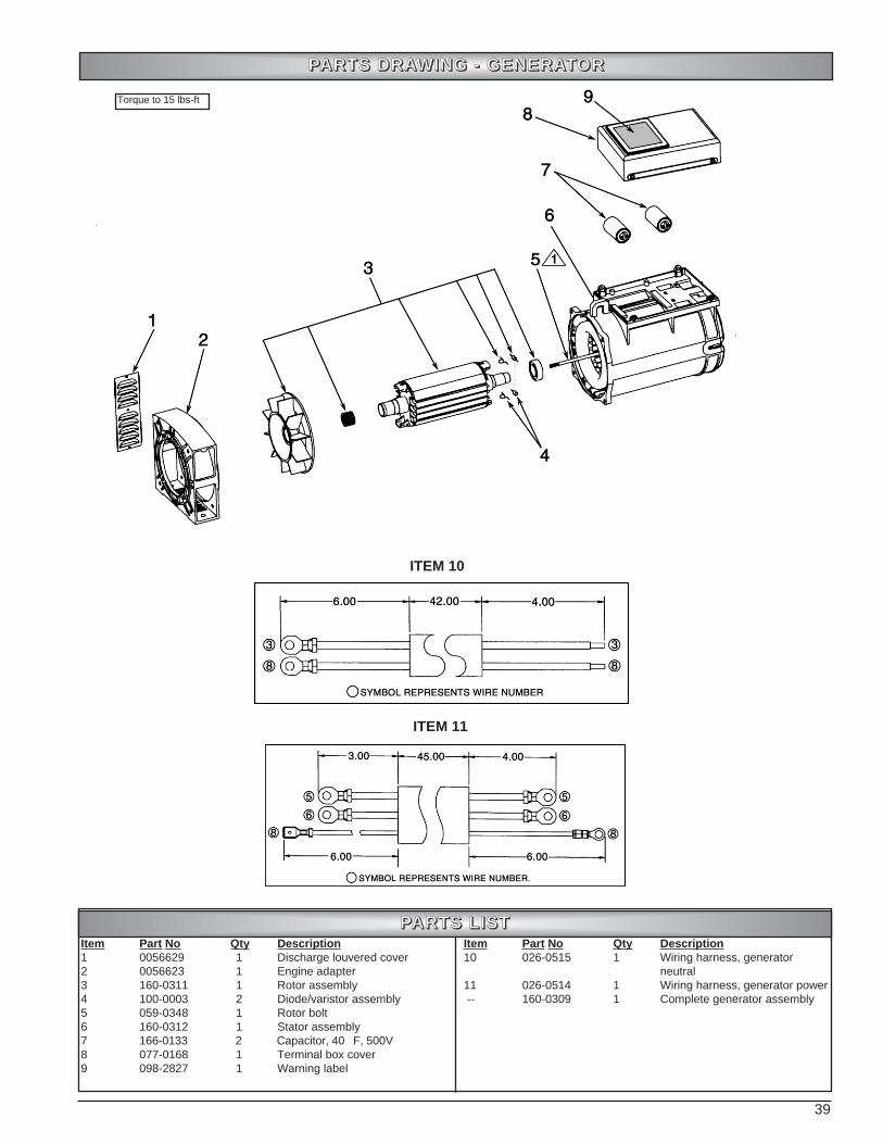
39
PPAARRTTSS DDRRAAWWIINNGG -- GGEENNEERRAATTOORR
Item Part No Qty Description1 0056629 1 Discharge louvered cover2 0056623 1 Engine adapter3 160-0311 1 Rotor assembly4 100-0003 2 Diode/varistor assembly5 059-0348 1 Rotor bolt6 160-0312 1 Stator assembly7 166-0133 2 Capacitor, 40F, 500V8 077-0168 1 Terminal box cover9 098-2827 1 Warning label
Item Part No Qty Description10 026-0515 1 Wiring harness, generator
neutral11 026-0514 1 Wiring harness, generator power-- 160-0309 1 Complete generator assembly
PPAARRTTSS LLIISSTT
ITEM 10
ITEM 11
Torque to 15 lbs-ft

40
PPAARRTTSS DDRRAAWWIINNGG -- FFRRAAMMEE AASSSSEEMMBBLLYY
Item Part No Qty Description1 094-0091 1 Insulation2 115-0268 1 Panel, left side (includes item 1)3 N/A 4 Screw, 10-32 x .50” lg4 N/A 1 Bolt, 5/16 NC x 1.25” lg5 N/A 1 Lock washer, 5/16”6 N/A 1 Washer, 5/16”7 160-0309 1 Generator assembly8 N/A 4 Bolt, 3/8-16 x .75” lg9 N/A 2 Bolt, 5/16 NC x 1.50” lg10 N/A 2 Lock washer, 5/16”11 025-0063 1 Engine, Honda, GX620 (muffler ...
not incl. - see page 36 for details)or 025-0059 1 Engine, Honda, GX670 (muffler ...
not incl. - see page 36 for details)12 N/A 12 Lag screw, 5/16 x 2” lg w/washer13 094-0074 1 Insulation14 115-0269 1 Exhaust access panel (includes
item 15)15 094-0081 1 Insulation16 094-0080 1 Insulation17 115-0270 1 Back panel (includes items 13 & 16)18 115-0245 1 Engine panel assembly (see
pages 41, 42 & 43 for details)19 094-0095 2 Spacer20 N/A 2 Screw, #10 x 1/2” sheet metal
Item Part No Qty Description21 109-0100 1 Base, plastic 22 071-0031 1 Hose clamp23 N/A 1 Screw, 10-14 x .63” lg24 S108-0160 1 Engine pan25 094-0068 3 Vibration isolator26 115-0271 1 Crossbrace assembly (includes
items 27, 28, 35, 35A & 36)27 098-2828 1 Warning label28 098-2821 1 Warning label29 068-0084 1 Fitting, hose barb 1/8 x 3/830 012-0094 1 Hose, oil drain31 012-0084 1 Hose clamp, .50-1.232 0057747 1 Fitting, barb 3/8 x 1/233 0057746 1 Valve ball, 3/8 M/F34 063-0042 1 Adapter, oil drain35 026-0309 1 Fuse holder35A 026-0518 1 Fuse, type 3AG, 25 Amp 32V36 026-0547 1 Relay DC, 12V, COIL37 S0049224 1 Ground strap, 12GA, 5.50” lg
*N/A - These are standard parts available at your local hardware store.
PPAARRTTSS LLIISSTT
Seedetail A
Detail A
Torque to 8.5 lbs-ft
Torque to 15 lbs-in
Torque to 40 lbs-ft
For Oil Filter and Air Filterpart numbers, see page 19of this manual.

41
PPAARRTTSS DDRRAAWWIINNGG -- EENNGGIINNEE PPAANNEELL AASSSSEEMMBBLLYY
Item Part No Qty Description1 094-0096 1 Insulation2 N/A 6 Hose clamp, 23/32” I.D.3 S012-0106 1 Hose, high temp oil, 3/8” x 26.5” lg4 N/A 10 Nut, 1/4-20, Nylon stop5 026-0338 1 GFCI Receptacle6 See page 42 1 Control panel assy, CP2007 N/A 2 Screw, 10-16 x .50” lg8 094-0095 4 Spacer, .75 O.D.9 N/A 4 Screw, 1/4-20 x .75” lg10 S115-0238 1 Control box frame11 115-0272 1 Panel, right hand (includes items
1 & 22)12 N/A 2 Screw, 6-32 x .50” lg13 026-0460 1 Terminal block, ground lug14 026-0472 1 Terminal block15 N/A 1 Screw, torx 8-32 x 1.25” lg16 N/A 2 Screw, 8-32 x 1.25” lg17 N/A 5 Nut, #8-32 (not shown - for items
15, 16 and 20)18 N/A 1 Rectifier shipped with engine
(Contact Honda Service Center)19 N/A 2 Bolt, 1/4-20 x 120 N/A 1 Screw, 8-32 x .75” lg21 026-0539 1 Terminal block, 2 row 20A 4-pole22 098-2800 1 Warning label23 N/A 1 Elbow, 1/2 NPT x 1/2 NPT
Item Part No Qty Description24 019-0211 1 Regulator assy, GX670
(PM401211)or 019-0213 1 Regulator assy, GX620
(PM400911)25 N/A 2 Bolt, 1/4-20 x 1.75” lg26 0057079 1 Oil cooler27 N/A 4 Bolt, 1/4-20 x .63” lg28 S114-0564 1 Bracket, oil cooler29 Order S012-0106 1 Hose, high temp oil, 3/8” x 3” lg30 069-0022 1 Tee, adapter oil temp31 Order S012-0106 1 Hose, high temp oil, 3/8” x 13” lg32 034-0162 1 Switch, oil temp33 051-0091 2 Bushing, snap .875 ID34 093-0053 1 Rubber grommet35 026-0512 1 Wire harness, engine control36 012-0120 1 Vapor hose assembly37 026-0516 1 Wire harness, terminal block
power 38 093-0054 1 Fuel grommet, .84 ID x 1.875 OD39 N/A 1 Nipple, 3” lg, 1/2 NPT40 098-2826 1 Warning label41 026-0309 1 Fuse holder42 N/A 1 Fuse, 5A Type 3AG43 098-2850 1 Fuse label
*N/A - These are standard parts available at your local hardware store.
PPAARRTTSS LLIISSTT
ITEM 37
Torque to 8.5 lbs-ft
Torque to 15 lbs-in

42
PPAARRTTSS DDRRAAWWIINNGG -- CCOONNTTRROOLL PPAANNEELL AASSSSEEMMBBLLYY
Item Part No Qty Description1 N/A 2 Screw #8-32 x .75 phillips hd2 034-0161 1 Switch, toggle3 032-0067 1 Hourmeter, 120V AC 60HZ4 (see #8) 1 Not available separately5 N/A 4 Screw, 6-32 x .38”lg6 N/A 4 Lock washer #67 115-0273 1 Control box top (includes item 14)8 0056884 1 Switch, momentary9 060-0175 4 Standoff, 6-32 x .75”lg10 026-0534 1 Controller board, CP20011 N/A 4 Nut #6-32, Nylon stop
Item Part No Qty Description12 002-0060 1 Circuit breaker, 50 Amp,
120/240V (PM401211)or 002-0061 1 Circuit breaker, 45 Amp,
120/240V (PM400911)13 0058069 1 Circuit breaker mount 14 098-2820 1 Control panel label, CP200 15 026-0537 1 Wire harness
*N/A - These are standard parts available at your local hardware store.
PPAARRTTSS LLIISSTT
Torque to 10 lbs-in
Torque to 15 lbs-in

43
PPAARRTTSS DDRRAAWWIINNGG -- BBAATTTTEERRYY HHOOLLDD DDOOWWNN
Item Part No Qty Description1 N/A 2 Nut, 1/4-202 S114-0563 1 Bracket, battery hold down3 026-0480 1 Battery cable, positive4 026-0481 1 Battery cable, negative5 N/A 1 Battery, BCI Group 26 or 26R6 059-0344 2 J-bolt, 1/4-207 S115-0229 1 Battery shelf8 0057024 4 Battery standoff, rubber9 N/A 2 Bolt, 1/4-20 x .625” lg10 N/A 2 Screw, 1/4-20 x 1” lg11 0057217 1 Battery charger 11A N/A 1 Fuse, type 3AG, 25 Amp, 32V12 N/A 2 Nut, nylon stop 1/4-2013 N/A 2 Nut, 1/4-20 nyloc
*N/A - These are standard parts available at your local hardware store.
PPAARRTTSS LLIISSTT
Torque to 7 lbs-ft
Torque to 8.5 lbs-ft

44
NOTES

45
NOTES
46
Coleman PowerStation™ Stationary Standby3-Year or 1500 Hour Limited Warranty
Your Coleman PowerStation™ emergency back up power system generator has been manufactured to stringent guidelines &standards for years of dependable operation & service. Coleman Powermate warrants this product to the original consumeragainst defects in material and workmanship for a period of 3-Years or 1500 hours, whichever occurs first, from the date ofpurchase and is not transferable.
Coverage:Replacement parts & labor, including travel time & mileage, for defects in product found to be properly installed, maintained &operated in accordance with Coleman Powermate & supplied component operator's manuals are eligible for warrantycoverage. A Coleman Powermate Authorized Master Representative, their dealer or their agent must perform warrantyservice. Items not covered under the warranty are:
Implied Warranties:Any implied warranties, including the Implied Warranties of Merchantability and Fitness For A Particular Purpose, are limitedin duration to 3-Years or 1500 Hours from the date of consumer purchase. Some states do not allow limitations on how longan implied warranty lasts, so the limitation may or may not apply to you.
How To Obtain Warranty Performance:Replacement parts & service are available from Coleman Powermate's Master Representative service network. Locate thenearest service location by calling 1-800-445-1805, or write: Coleman Powermate Inc., 4970 Airport Road, PO Box 6001,Kearney NE 68848.
To the extent any provision of this warranty is prohibited by federal, state, or municipal law, and cannot be preempted, it shallnot be applicable. This warranty gives you specific rights, and you may have other rights which may vary from state to state.
⇒ Normal engine wear, tune-ups, and routine service.⇒ Damage caused by shipping, accidents, improper installation
or handling, improper storage, or repairs not performed by a Coleman Powermate authorized Master Representative, their dealer or their agent.
⇒ Damage caused by operation with improper fuel or at speeds, loads, conditions, modifications, or installation contrary to published specifications or recommendations.
⇒ Damage caused by negligent maintenance such as:- Failing to provide the specified type and sufficient quantity of
lubricating oil.- Failing to keep the air intake and cooling areas clean.- Failing to service the air cleaner.- Failing to provide sufficient coolant.- Failing to perform scheduled maintenance as recommended
by Coleman Powermate or by supplied component manufacturers.
- Failing to regularly exercise the generator.⇒ Original installation charges and startup costs.⇒ Starting batteries, travel & labor associated with battery failure.⇒ Rental of equipment during performance of warranty repairs.⇒ Engines, or other components, which are covered exclusively
by the warranty of their manufacturer.⇒ Altered, tampered or improperly maintained emission control
system components.
⇒ Parts purchased for a replacement of a failed Coleman Powermate part with a non-Coleman Powermate part voids warranty on that part.
⇒ Fuel injection pumps not repaired locally by an authorized servicing dealer.
⇒ Non-Coleman Powermate-authorized repair shop labor withoutprior approval from Coleman Powermate Warranty Department.
⇒ Engine fluids such as fuel, oil, or coolant/antifreeze.⇒ Expenses incurred investigating performance complaints
unless defective Coleman Powermate materials or workmanship is the cause of the problem.
⇒ Maintenance items such as fuses lamps, filters, spark plugs and adjustments.
⇒ Sales outside the U.S. or Canada⇒ Telephone charges or transportation charges in connection
with the repair of defective parts.⇒ Overtime labor charges incurred at the request of owner unless
prior approval is obtained by Coleman Powermate.⇒ Air freight charges or shipping charges outside of Coleman
Powermate shipping practices⇒ Any other expense including consequential damages,
incidental damages, or incidental expenses, including damage to property. Some states do not allow the exclusion or limitation of incidental damages, so the limitation may not applyto you.
Coleman® is a registered trademark of theColeman Company, Inc. used under license.© 2001 Coleman Powermate, Inc.
47
COMUNÍQUESE CON EL DEPARTAMENTO DE SERVICIO DE PRODUCTOS COLEMANPOWERMATE EN EL TELÉFONO
308-236-4527para obtener información sobre servicios de garantía o para pedir piezas de repuesto o
accesorios.
CÓMO PEDIR PIEZAS DE REPUESTOIncluso los equipos de calidad como el generador de emergencia Coleman Powermate que ha
comprado necesitan ocasionalmente piezas de repuesto para mantenerlos en buenas condiciones através de los años. Para pedir piezas de repuesto, sírvase entregar la información siguiente:
1. N.º de modelo y de serie y todas las especificaciones que se muestran en la placa de N.º de Modelo/N.º de Serie.
2. Una descripción breve del problema con el generador.
APPELER LE SERVICE DES PRODUITS COLEMAN POWERMATE AU 1-800-445-1805 pour obtenirdes informations sur le service de garantie ou pour commander des pièces ou des accessoires.
COMMENT COMMANDER DES PIÈCES DE RECHANGEMême l'équipement de première qualité, comme la génératrice de réserve Coleman Powermate quevous avez achetée, peut nécessiter occasionnellement des pièces de rechange pour demeurer en
parfait état de marche au fil des années. Pour commander des pièces, veuillez indiquer lesrenseignements suivants :
1. Le n° de modèle et le n° de série ainsi que toutes spécifications figurant sur la plaque signalétique des numéros de modèle et de série.
2. Une brève description du problème de la génératrice.
CONTACT THE COLEMAN POWERMATE PRODUCT SERVICE DEPARTMENT AT1-800-445-1805
to obtain warranty service information or to order replacement parts or accessories.
HOW TO ORDER REPLACEMENT PARTSEven quality built equipment such as the Coleman Powermate standby generator you have
purchased, might need occasional replacement parts to maintain it in good condition over theyears. To order replacement parts, please give the following information:
1. Model No. and Serial No. and all specifications shown on the Model No./Serial No. plate.2. A brief description of the trouble with the generator.
Coleman Powermate, Inc.4970 Airport Road
P. O. Box 6001Kearney, NE 68848
1-800-445-18051-308-237-2181
Fax 1-308-234-4187

48