owner’s manual - seat this is a general manual for the mii, some of the equipment and functions...
TRANSCRIPT

OWNER’S MANUAL
Mii
1SL012720BC
Ingl
és 1
SL0
1272
0BC
(11
.14)
Mii
Ing
lés
(11
.14)

SEAT S.A. is permanently concerned about continuous development of its types and models. For this reason we ask you to under-stand, that at any given time, changes regarding shape, equipment and technique may take place on the car delivered. For this reason no right at all may derive based on the data, drawings and descriptions in this current handbook.
All texts, illustrations and standards in this handbook are based on the status of information at the time of printing. Except for error or omission, the information included in the current handbook is valid as of the date of closing print.
Re-printing, copying or translating, whether total or partial is not allowed unless SEAT allows it in written form.
SEAT reserves all rights in accordance with the “Copyright” Act.
All rights on changes are reserved.
❀ This paper has been manufactured using bleached non-chlorine cellulose.
© SEAT S.A. - Reprint: 15.11.14
About this manual
This manual contains a description of the equipment supplied with the vehicle at the time this manual was published. Some of the units described herein will not be available until a later date or are only available in cer-tain markets.
Because this is a general manual for the MII, some of the equipment and functions that are described in this manual are not included in all types or variants of the model; they may vary or be modified depending on the techni-cal requirements and on the market; this is in no way deceptive advertising.
The illustrations are intended as a general guide and may vary from the equipment fitted in your vehicle in some details.
The steering indications (left, right, forward, reverse) appearing in this manual refer to the normal driving movements of the vehicle ex-cept when otherwise indicated.
* The equipment marked with an aster-isk* is fitted as standard only in certain versions, and is only supplied as op-tional extras for some versions, or are only offered in certain countries.
® All registered marks are indicated with ®. Although the copyright symbol does not appear, it is a copyrighted mark.
>> The section is continued on the follow-ing page.
WARNING
Texts preceded by this symbol contain infor-mation on safety. They warn you about possi-ble dangers of accident or injury.
CAUTION
Texts with this symbol draw your attention to potential sources of damage to your vehicle.
For the sake of the environment
Texts preceded by this symbol contain rele-vant information concerning environmental protection.
Note
Texts preceded by this symbol contain additio-nal information.
This manual is divided into five large parts, which are:
1. Safety
2. Operation
3. Tips
4. Technical data
5. Alphabetical index
At the end of this manual, there is a detailed alphabetical index that will help you quickly find the information you require.

ForewordThis Instruction Manual and its correspond-ing supplements should be read carefully tofamiliarise yourself with your vehicle.
Besides the regular care and maintenance ofthe vehicle, its correct handling will help pre-serve its value.
For safety reasons, always note the informa-tion concerning accessories, modificationsand part replacements.
If selling the vehicle, give all of the on-boarddocumentation to the new owner, as itshould be kept with the vehicle.
You can access the information in this man-ual using:
● Thematic table of contents that follows themanual’s general chapter structure.
● Alphabetical index with many terms andsynonyms to help you find information.
WARNING
Read and always observe safety informa-tion concerning the passenger's front air-bag ››› page 25, Important informationregarding the front passenger's airbag.


Table of Contents
Table of ContentsSafety . . . . . . . . . . . . . . . . . . . . . . . . . . . . . . . . 5Safe driving . . . . . . . . . . . . . . . . . . . . . . . . . . . . 5Safety first! . . . . . . . . . . . . . . . . . . . . . . . . . . . . . 5Tips for driving . . . . . . . . . . . . . . . . . . . . . . . . . . 5Correct sitting position for vehicle occupants . 6Pedal area . . . . . . . . . . . . . . . . . . . . . . . . . . . . . . 10Seat belts . . . . . . . . . . . . . . . . . . . . . . . . . . . . . . 11Using seat belts . . . . . . . . . . . . . . . . . . . . . . . . . 11How to properly adjust your seatbelt . . . . . . . . 15Seat belt tensioners . . . . . . . . . . . . . . . . . . . . . . 16Airbag system . . . . . . . . . . . . . . . . . . . . . . . . . . 17Brief introduction . . . . . . . . . . . . . . . . . . . . . . . . 17General overview of the airbag . . . . . . . . . . . . . 21Deactivating airbags . . . . . . . . . . . . . . . . . . . . . 23Transporting children safely . . . . . . . . . . . . . . . 25Child safety . . . . . . . . . . . . . . . . . . . . . . . . . . . . . 25
Operation . . . . . . . . . . . . . . . . . . . . . . . . . . . . . 35Cockpit . . . . . . . . . . . . . . . . . . . . . . . . . . . . . . . . 35Overview . . . . . . . . . . . . . . . . . . . . . . . . . . . . . . . 34Instruments . . . . . . . . . . . . . . . . . . . . . . . . . . . . 36Control lamps . . . . . . . . . . . . . . . . . . . . . . . . . . . 39SEAT information system . . . . . . . . . . . . . . . . . . 40Opening and closing . . . . . . . . . . . . . . . . . . . . . 43Vehicle key set . . . . . . . . . . . . . . . . . . . . . . . . . . 43Central locking* and locking system . . . . . . . . 45Doors . . . . . . . . . . . . . . . . . . . . . . . . . . . . . . . . . . 49Rear lid . . . . . . . . . . . . . . . . . . . . . . . . . . . . . . . . 50Electric windows . . . . . . . . . . . . . . . . . . . . . . . . . 52Sliding/tilting electric panoramic sunroof . . . . 53Lights and visibility . . . . . . . . . . . . . . . . . . . . . . 55Lights . . . . . . . . . . . . . . . . . . . . . . . . . . . . . . . . . 55Visibility . . . . . . . . . . . . . . . . . . . . . . . . . . . . . . . 59
Windscreen wiper and rear window wipersystems . . . . . . . . . . . . . . . . . . . . . . . . . . . . . . . . 60Rear vision mirror . . . . . . . . . . . . . . . . . . . . . . . . 61Seats and head restraints . . . . . . . . . . . . . . . . . 63Adjusting the seat and head restraints . . . . . . 63Seat functions . . . . . . . . . . . . . . . . . . . . . . . . . . 64Transport and practical equipment . . . . . . . . . 65Transporting objects . . . . . . . . . . . . . . . . . . . . . 65Practical equipment . . . . . . . . . . . . . . . . . . . . . . 67Loading luggage compartment . . . . . . . . . . . . . 73Roof carrier system . . . . . . . . . . . . . . . . . . . . . . . 77Air conditioning . . . . . . . . . . . . . . . . . . . . . . . . . 80Heating, ventilation and air conditioningsystem . . . . . . . . . . . . . . . . . . . . . . . . . . . . . . . . . 80Driving . . . . . . . . . . . . . . . . . . . . . . . . . . . . . . . . 84Steering . . . . . . . . . . . . . . . . . . . . . . . . . . . . . . . 84Stopping and starting the engine . . . . . . . . . . . 86Braking and parking . . . . . . . . . . . . . . . . . . . . . 89Changing gear . . . . . . . . . . . . . . . . . . . . . . . . . . 93Run-in and economical driving . . . . . . . . . . . . . 98Engine management and exhaust gaspurification system . . . . . . . . . . . . . . . . . . . . . . 101Driving abroad . . . . . . . . . . . . . . . . . . . . . . . . . . 102Driving along flooded roadways . . . . . . . . . . . . 103Driver assistance systems . . . . . . . . . . . . . . . . . 103Braking and stability systems . . . . . . . . . . . . . . 103Parking sensor system* . . . . . . . . . . . . . . . . . . . 105Cruise control* (Cruise control system - CCS) . . 107Safety Assist* (City Safety Assist function) . . . . 110Hill driving assistant* . . . . . . . . . . . . . . . . . . . . 114Start-Stop system . . . . . . . . . . . . . . . . . . . . . . . . 115Towing bracket device . . . . . . . . . . . . . . . . . . . . 117Trailer coupling . . . . . . . . . . . . . . . . . . . . . . . . . . 117
Advice . . . . . . . . . . . . . . . . . . . . . . . . . . . . . . . . 118Care and maintenance . . . . . . . . . . . . . . . . . . . . 118Accessories, replacement of parts andmodifications . . . . . . . . . . . . . . . . . . . . . . . . . . . 118Care and cleaning the vehicle exterior . . . . . . . 125Caring for and cleaning the vehicle interior . . . 131Notes for the user . . . . . . . . . . . . . . . . . . . . . . . . 134Checking and refilling levels . . . . . . . . . . . . . . . 137Fuel . . . . . . . . . . . . . . . . . . . . . . . . . . . . . . . . . . . 137Filling the tank . . . . . . . . . . . . . . . . . . . . . . . . . . 139Bonnet . . . . . . . . . . . . . . . . . . . . . . . . . . . . . . . . 143Engine oil . . . . . . . . . . . . . . . . . . . . . . . . . . . . . . 146Engine coolant . . . . . . . . . . . . . . . . . . . . . . . . . . 150Brake fluid . . . . . . . . . . . . . . . . . . . . . . . . . . . . . 152Checking and topping up the windscreenwasher reservoir with water . . . . . . . . . . . . . . . . 154Vehicle battery . . . . . . . . . . . . . . . . . . . . . . . . . . 154Wheels and tyres . . . . . . . . . . . . . . . . . . . . . . . . 158Wheels . . . . . . . . . . . . . . . . . . . . . . . . . . . . . . . . 158Emergencies . . . . . . . . . . . . . . . . . . . . . . . . . . . . 170In case of emergency . . . . . . . . . . . . . . . . . . . . . 170Vehicle tool kit* . . . . . . . . . . . . . . . . . . . . . . . . . 172Changing a wheel . . . . . . . . . . . . . . . . . . . . . . . 174Tyre repair . . . . . . . . . . . . . . . . . . . . . . . . . . . . . . 178Starting assistance . . . . . . . . . . . . . . . . . . . . . . 181Towing and tow starting . . . . . . . . . . . . . . . . . . . 183Emergency locking and unlocking . . . . . . . . . . 186Changing the windscreen wiper blades . . . . . . 188Fuses and bulbs . . . . . . . . . . . . . . . . . . . . . . . . . 189Fuses . . . . . . . . . . . . . . . . . . . . . . . . . . . . . . . . . . 189Changing bulbs . . . . . . . . . . . . . . . . . . . . . . . . . 191
Technical specifications . . . . . . . . . . . . . . . 197Technical features . . . . . . . . . . . . . . . . . . . . . . . 197Important information . . . . . . . . . . . . . . . . . . . . 197Wheels . . . . . . . . . . . . . . . . . . . . . . . . . . . . . . . . 199Engine specifications . . . . . . . . . . . . . . . . . . . . . 200
3

Table of Contents
Dimensions . . . . . . . . . . . . . . . . . . . . . . . . . . . . . 203Capacities . . . . . . . . . . . . . . . . . . . . . . . . . . . . . . 203
Index . . . . . . . . . . . . . . . . . . . . . . . . . . . . . . . . . 205
4

Safe driving
Safety
Safe driving
Safety first!
WARNING
● This manual contains important informa-tion about the operation of the vehicle, bothfor the driver and the passengers. The othersections of the on-board documentation alsocontain further information that you shouldbe aware of for your own safety and for thesafety of your passengers.
● Ensure that the on-board documentation iskept in the vehicle at all times. This is espe-cially important when lending or selling thevehicle to another person.
WARNING
Driving under the influence of alcohol, drugs,medication or narcotics may result in severeaccidents and even loss of life.
● Alcohol, drugs, medication and narcoticsmay significantly alter perception, affect re-action times and safety while driving, whichcould result in the loss of control of the vehi-cle.
Tips for driving
Before starting every trip
For your own safety and the safety of yourpassengers, always note the following pointsbefore every trip:
– Make sure that the vehicle's lights and turnsignals are working properly.
– Check tyre pressure.
– Ensure that all windows provide a clear andgood view of the surroundings.
– Make sure all luggage is secured››› page 65.
– Make sure that no objects can interferewith the pedals.
– Adjust front seat, head restraint and rear vi-sion mirrors properly according to yoursize.
– Ensure that the passengers in the rearseats always have the head restraints inthe in-use position ››› page 9.
– Instruct passengers to adjust the head re-straints according to their height.
– Protect children with appropriate childseats and properly applied seat belts››› page 25.
– Assume the correct sitting position. Instructyour passengers also to assume a propersitting position. ››› page 6.
– Fasten your seat belt securely. Instruct yourpassengers also to fasten their seat beltsproperly. ››› page 11.
What affects driving safety?
As a driver, you are responsible for yourselfand your passengers. When your concentra-tion or driving safety is affected by any cir-cumstance, you endanger yourself as well asothers on the road ››› , for this reason:
– Always pay attention to traffic and do notget distracted by passengers or telephonecalls.
– Never drive when your driving ability is im-paired (e.g. by medication, alcohol, drugs).
– Observe traffic laws and speed limits.
– Always reduce your speed as appropriatefor road, traffic and weather conditions.
– When travelling long distances, takebreaks regularly - at least every two hours.
– If possible, avoid driving when you are tiredor stressed. »
5
Tech
nica
l spe
cific
atio
nsA
dvic
eO
pera
tion
Saf
ety

Safety
WARNING
When driving safety is impaired during a trip,the risk of injury and accidents increases.
Safety equipment
Never put your safety or the safety of yourpassengers in danger. In the event of an acci-dent, the safety equipment may reduce therisk of injury. The following list includes mostof the safety equipment in your SEAT:
● Three-point seat belts
● belt tension limiters for the front and rearside seats,
● Belt tensioners for the front seats
● Belt height adjustment for the front seats
● Front airbags
● Side airbags in the front seat backrests
● Side airbags in the rear seat backrests*
● Head-protection airbags
● Active front head restraints*
● “ISOFIX” anchor points for child seats inthe rear side seats with the “ISOFIX” system,
● Height-adjustable front head restraints
● Rear head restraints with in-use positionand non-use position
● Adjustable steering column
The safety equipment mentioned aboveworks together to provide you and your pas-sengers with the best possible protection inthe event of an accident. However, thesesafety systems can only be effective if youand your passengers are sitting in a correctposition and use this equipment properly.
Safety is everyone's business!
Correct sitting position forvehicle occupants
Correct sitting position
Fig. 1 The proper distance between driverand steering wheel
Fig. 2 Correct belt web and head restraint po-sitions
The correct sitting positions for the driver andpassengers are shown below.
If your physical constitution prevents youfrom maintaining the correct sitting position,contact a specialised workshop for help withany special devices. The seat belt and airbagcan only provide optimum protection if a cor-rect sitting position is adopted. SEAT recom-mends taking your car in for technical serv-ice.
For your own safety and to reduce the risk ofinjury in the event of an accident or suddenbraking or manoeuvre, SEAT recommend thefollowing positions:
Valid for the driver:
● Adjust the seat backrest to an upright posi-tion so that your back rests completelyagainst it.
6

Safe driving
● Adjust the seat so that there is a distanceof at least 25 cm between the steering wheeland your chest ››› Fig. 1 and so that you canhold the steering wheel with both hands onthe outside of the ring at the 9 o'clock and 3o'clock positions with your arms slightlybent.
● The adjusted steering wheel must face yourchest and not your face.
● Adjust the driver seat forwards or back-wards so that you are able to press the accel-erator, brake and clutch pedals to the floorwith your knees slightly angled and the dis-tance between your knees and the dash pan-el is at least 10 cm ››› Fig. 1.
● Adjust the height of the driver seat so thatyou can easily reach the top of the steeringwheel.
● Keep both feet in the footwell so that youhave the vehicle under control at all times.
● Adjust and fasten your seat belt correctly››› page 11.
Valid for the passenger:
● Adjust the seat backrest to an upright posi-tion so that your back rests completelyagainst it.
● Move the front passenger seat back as faras possible for optimum protection shouldthe airbag deploy.
● Always keep your feet in the footwell whilethe vehicle is in motion.
● Adjust and fasten your seat belt correctly››› page 11.
Valid for the passengers in the rear section:
● Adjust the head restraint so that its upperedge is at the same level as the top of yourhead, or as close as possible to the same lev-el as the top of your head and under no cir-cumstances below eye level. Keep the backof your neck as close as possible to the headrestraint ››› Fig. 1 and ››› Fig. 2.
● Short people must lower the head restraintto the first anchorage position, even if yourhead is below its upper edge.
● Tall people must raise the head restraintcompletely.
● Always keep your feet in the footwell whilethe vehicle is in motion.
● Adjust and fasten your seat belt correctly››› page 11.
Adjusting the steering wheel position
Fig. 3 Mechanical steering wheel adjustment
Adjust the steering wheel before your tripand only when the vehicle is stationary.
● Push the lever ››› Fig. 3 1 downwards.
● Adjust the steering wheel so that you canhold onto the steering wheel with both handson the outside of the ring at the 9 o'clock and3 o'clock positions and your arms slightlybent.
● Push the lever firmly upwards until it isflush to the steering column ››› .
Adjust the correct distance between the driv-er and the steering wheel ››› Fig. 1 using thecontrols on the driver seat ››› page 63. »
7
Tech
nica
l spe
cific
atio
nsA
dvic
eO
pera
tion
Saf
ety

Safety
WARNING
Incorrect use of the steering wheel adjust-ment function and an incorrect adjustment ofthe steering wheel can result in severe or fa-tal injury.
● After adjusting the steering column, pushthe lever ››› Fig. 3 1 firmly upwards to en-sure the steering wheel does not accidentallychange position while driving.
● Never adjust the steering wheel while thevehicle is in motion. If you need to adjust thesteering wheel while the vehicle is in motion,stop safely and make the proper adjustment.
● The adjusted steering wheel should be fac-ing your chest and not your face so as not tohinder the driver's front airbag protection inthe event of an accident.
● When driving, always hold the steeringwheel with both hands on the outside of thering at the 9 o'clock and 3 o'clock positionsto reduce injuries when the driver's front air-bag deploys.
● Never hold the steering wheel at the 12o'clock position or in any other manner (e.g.in the centre of the steering wheel). In suchcases, if the driver's airbag deploys, you maysustain injuries to your arms, hands andhead.
Danger of injuries due to an incorrectsitting position
Number of seats
The vehicle has a total of 4 seats: 2 frontseats and 2 rear seats. Each seat is equippedwith a seat belt.
If the seat belts are worn incorrectly or not atall, the risk of severe injuries increases. Seatbelts can provide optimal protection only ifthe belt web is properly worn. Being seatedin an incorrect position means the seat beltcannot offer its full protection. This could re-sult in severe and even fatal injuries. The riskof severe or fatal injuries is especially height-ened when a deploying airbag strikes a vehi-cle occupant who has assumed an incorrectsitting position. The driver is responsible forall passengers in the vehicle, particularlychildren.
The following list shows just some examplesof incorrect sitting positions which can bedangerous to all vehicle occupants.
When the vehicle is in motion:
● Never stand in the vehicle.
● Never stand on the seats.
● Never kneel on the seats.
● Never tilt your seat backrest too far to therear.
● Never lean against the dash panel.
● Never lie on the rear seats.
● Never sit on the front edge of a seat.
● Never sit sideways.
● Never lean out of a window.
● Never put your feet out of a window.
● Never put your feet on the dash panel.
● Never put your feet on the surface of a seator seat backrest.
● Never travel in a footwell.
● Never travel on a seat without wearing theseat belt.
● Never carry any person in the luggage com-partment.
WARNING
An incorrect sitting position in the vehiclecan lead to severe injuries or death in theevent of sudden braking or manoeuvres, colli-sion or accidents or if the airbag deploys.
● Before the vehicle moves, assume the prop-er sitting position and maintain it throughoutthe trip. This also includes fastening the seatbelt.
● Never transport more people than there areseats with a seat belt available in the vehicle.
● Children must always be protected with anapproved child restraint system suited totheir height and weight ››› page 25,››› page 17.
8

Safe driving
● Always keep your feet in the footwell whilethe vehicle is in motion. Never, for example,put your feet on the surface of a seat or onthe dash panel and never put them out of awindow. Otherwise the airbag and seat beltoffer insufficient protection and the risk of in-jury in the event of an accident is increased.
WARNING
Before every trip, adjust the seat, the seatbelt and the head restraints and instruct yourpassengers to fasten their seat belts proper-ly.
● Move the front passenger seat back as faras possible.
● Adjust the driver seat so that there is atleast 25 cm distance between your chest andthe hub of the steering wheel. Adjust thedriver seat so that you are able to press theaccelerator, brake and clutch pedals to thefloor with your knees slightly angled and thatthe distance between your knees and thedash panel is at least 10 cm. If your physicalconstitution prevents you from meeting theserequirements, contact a specialised work-shop to make any modifications required.
● Never drive with the seat backrest tilted farback. The further the seat backrests are tiltedto the rear, the greater the risk of injury dueto incorrect positioning of the belt web or tothe incorrect sitting position!
● Never drive with the seat backrest tiltedforwards. Should a front airbag deploy, it
could throw the seat backrest backwards andinjure the passengers of the rear seats.
● Sit as far away as possible from the steer-ing wheel and the dash panel.
● Keep your back straight and resting com-pletely against the seat backrest and thefront seats correctly adjusted. Never placeany part of your body in the area of the airbagor very close to it.
● If passengers on the rear seats are not sit-ting in an upright position, the risk of severeinjury due to incorrect positioning of the beltweb increases.
WARNING
Incorrect seat adjustment may lead to acci-dents and severe injuries.
● Only adjust the seats when the vehicle isstationary, as the seats could move unex-pectedly while the vehicle is in motion andyou could lose control of the vehicle. Further-more, an incorrect position is adopted whenadjusting the seat.
● Only adjust the height, seat backrest andforwards or backwards position of the seatwhen there is nobody in the seat adjustmentarea.
● There must be no objects blocking the frontseat adjustment area.
Adjust the rear head restraints
Fig. 4 Adjusting the rear head restraints
All seats are equipped with a head restraint.
The front seat head restraints are integratedin the backrests and adjusting them is notpossible.
Adjusting height
● Push the head restraint up or down in thedirection of the arrow with the button press-ed ››› Fig. 4 1 ››› .
● The head restraint must engage securely inposition.
Correct adjustment of head restraints
Adjust the head restraint so that its upperedge is at the same level as the top of yourhead, or as close as possible to the same lev-el as the top of your head and under no cir-cumstances below eye level. Keep the back »
9
Tech
nica
l spe
cific
atio
nsA
dvic
eO
pera
tion
Saf
ety

Safety
of your neck as close as possible to the headrestraint.
Adjusting the head restraint for short people
Set the head restraint in the first anchorageposition, even if your head is below its upperedge. When the head restraint is at its low-est, it is possible that a small gap remainsbetween it and the seat backrest.
Adjusting the head restraint for tall people
Raise the head restraint completely.
WARNING
Travelling with the head restraints removedor improperly adjusted increases the risk ofsevere or fatal injuries in the event of acci-dents and sudden braking or manoeuvres.
● Always fit and adjust the head restraintproperly whenever a person is occupying aseat.
● All vehicle occupants must correctly adjustthe head restraint according to their height toreduce the risk of back injuries in the event ofan accident. The upper edge of the head re-straint must be as close as possible to thesame level as the top of your head and underno circumstances below eye level. Keep theback of your neck as close as possible to thehead restraint.
● Never adjust the head restraint while thevehicle is in motion.
Pedal area
Pedals
Do not allow floor mats or other objects toobstruct the free passage of the pedals.
Floor mats should leave the pedal area freeand unobstructed and be correctly secured inthe footwell zone.
In the event of failure of a brake circuit, thebrake pedal must be pressed harder thannormal to brake the vehicle.
WARNING
Objects falling into the driver's footwell couldprevent use of the pedals. This could lead thedriver to lose control of the vehicle, increas-ing the risk of a serious accident.
● Make sure the pedals can be used at alltimes, with no objects rolling underneaththem.
● Always secure the mat in the footwell.
● Never place other mats or rugs on top ofthe original mat supplied by the factory.
● Ensure that no objects can fall into the driv-er's footwell while the vehicle is in motion.
CAUTION
The pedals must always have free and unob-structed passage to the floor. For example, incase of a fault in the brake circuit, the brake
pedal will need to be pressed further to stopthe vehicle. To press the brake pedal downfurther will require more force than usual.
10

Seat belts
Seat belts
Using seat belts
Introduction
Check the condition of all the seat belts atregular intervals. If you notice that the beltwebbing, fittings, retractor mechanism orbuckle of any of the belts is damaged, thebelt must be replaced immediately by a spe-cialised workshop ››› . The specialisedworkshop must use the appropriate spareparts corresponding to the vehicle, theequipment and the model year. SEAT recom-mends taking your car in for technical serv-ice.
WARNING
Unbuckled or badly buckled seat belts in-crease the risk of severe or even fatal inju-ries. The seat belt cannot offer its full protec-tion if it is not fastened and used correctly.
● Seat belts are the most effective way of re-ducing the risk of sustaining severe or fatalinjuries in the event of an accident. Seat beltsmust be correctly fastened when the vehicleis in motion to protect the driver and all vehi-cle occupants.
● Before each trip, every occupant in the ve-hicle occupants must sit properly, correctlyfasten the seat belt belonging to his or herseat and keep it fastened throughout the trip.
This also applies to other vehicle occupantswhen driving in town.
● When travelling, children must be securedin the vehicle with a child restraint systemsuitable for their weight and height and withthe seat belts correctly fastened››› page 25.
● Instruct your passengers to fasten theirseat belts properly before driving off.
● Insert the latch plate into the buckle for theappropriate seat and ensure it is engaged.Using the latch plate in the buckle of anotherseat will not protect you properly and maycause severe injuries.
● Do not allow liquids or foreign bodies to en-ter the buckle fastenings. This could damagethe buckles and seat belts.
● Never unbuckle your seat belt when the ve-hicle is moving.
● Never allow more than one passenger toshare the same seat belt.
● Never hold children or babies on your lapsharing the same seat belt.
● Loose, bulky clothing (such as a jacket) im-pairs the proper fit and function of the seatbelt.
WARNING
It is extremely dangerous to drive using dam-aged seat belts and could result in serious in-jury or loss of life.
● Avoid damaging the seat belt by jamming itin the door or the seat mechanism.
● If the fabric or other parts of the seat beltare damaged, the seat belts could break inthe event of an accident or sudden braking.
● Always have damaged seatbelts replacedimmediately by seat belts approved for thevehicle in question by SEAT. Seat belts whichhave been worn in an accident and stretchedmust be replaced by a specialised workshop.Renewal may be necessary even if there is noapparent damage. The belt anchorage shouldalso be checked.
● Never attempt to repair, modify or remove aseat belt yourself. All repairs to seat belts, re-tractors and buckles must be carried out by aspecialised workshop.
11
Tech
nica
l spe
cific
atio
nsA
dvic
eO
pera
tion
Saf
ety

Safety
Warning lamp
Fig. 5 Warning lamp on the instrument panel
Fig. 6 Indication of seat belt status in the rearseats on the instrument panel display
Lightsup or
flashesPossible cause Solution
On the instrument panel:Driver's seat belt not fas-tened or front passengerseat belt not fastened ifthe front passenger seatis occupied.
Fasten seatbelts!
On the instrument panel:Objects on the front pas-senger seat.
Remove anyobjects fromthe front pas-senger seatand store themsafely.
Instrument panel dis-play: a passenger in therear seats has not fas-tened their seat belt, ifthe seat is occupied.*
Fasten seatbelts!
On the instrument paneldisplay: a passenger inthe rear seats has fas-tened their seat belt, ifthe seat is occupied.*
Several warning and control lamps light upfor a few seconds when the ignition is switch-ed on, signalling that the function is beingverified. They will switch off after a few sec-onds.
An audible warning will be heard if the seatbelts are not fastened as the vehicle drivesoff and reaches a speed of more then
25 km/h (15 mph) or if the seat belts are un-fastened while the vehicle is in motion. Theseat belt warning lamp will also flash.
The warning lamp does not switch off untilthe driver and front passenger fasten theirseat belts while the ignition is switched on.
Seat belt status display for rear seats
The seat belt status display on the instru-ment panel informs the driver, when the igni-tion is switched on, whether any passengersin the rear seats have fastened their seatbelts. The symbol indicates that the pas-senger in this seat has fastened “his or her”seat belt ››› Fig. 6.
The seat belt status is displayed for around30 seconds when a seat belt in the rear seatsis fastened or unfastened. You can switch offthis display by pressing the 0.0 / SET button.
The seat belt status flashes for a maximum of30 seconds when a seat belt in the rear seatsis unfastened while the vehicle is in motion.An audible warning will also be heard if thevehicle is travelling at over 25 km/h(15 mph).
12

Seat belts
Seat belt protection
Fig. 7 Drivers with properly worn seat beltswill not be thrown forward in the event of sud-den braking
Properly worn seat belts hold the occupantsin the proper position. They also help preventuncontrolled movements that may result inserious injury and reduce the risk of beingthrown out of the vehicle in case of an acci-dent.
Vehicle occupants wearing their seat beltscorrectly benefit greatly from the ability of thebelts to absorb kinetic energy. In addition,the front part of your vehicle and other pas-sive safety features (such as the airbag sys-tem) are designed to absorb the kinetic ener-gy released in a collision. Taken together, allthese features reduce the releasing kineticenergy and consequently, the risk of injury.This is why it is so important to fasten seatbelts before every trip, even when "just driv-ing around the corner".
Ensure that your passengers wear their seatbelts as well. Accident statistics have shownthat wearing seat belts is an effective meansof substantially reducing the risk of injuryand improving the chances of survival wheninvolved in a serious accident. Furthermore,properly worn seat belts improve the protec-tion provided by airbags in the event of anaccident. For this reason, wearing a seat beltis required by law in most countries.
Although your vehicle is equipped with air-bags, the seat belts must be fastened andworn. The front airbags, for example, are onlytriggered in some cases of head-on collision.The front airbags will not be triggered duringminor frontal or side collisions, rear-end colli-sions, rollovers or accidents in which the air-bag trigger threshold value in the control unitis not exceeded.
Therefore, you should always wear your seatbelt and ensure that all vehicle occupantshave fastened their seat belts properly beforeyou drive off!
Using seat belts
Twisted seat belt
If it is difficult to remove the seat belt fromthe guide, the seat belt may have becometwisted inside the side trim after beingwound too quickly on unfastening:
● Pull out the seat belt completely, carefullypulling on the latch plate.
● Untwist the belt and guide it back, assist-ing it by hand.
The seat belt must be fastened even if it isimpossible to untwist it. In this case, thetwisted area must not be in an area in directcontact with your body. Have the seat beltuntwisted urgently by a specialised work-shop.
WARNING
An improperly handled seat belt increasesthe risk of sustaining severe or fatal injuries.
● Regularly check that the seat belts andtheir components are in perfect condition.
● Always keep your seat belt clean.
● Do not jam or damage the seat belt or rub itwith sharp edges.
● Make sure there are no liquids or foreignbodies on the latch plate and in the buckle.
13
Tech
nica
l spe
cific
atio
nsA
dvic
eO
pera
tion
Saf
ety

Safety
Head-on collisions and the laws ofphysics
Fig. 8 A driver not wearing a seat belt isthrown forward violently
Fig. 9 The unbelted passenger in the rearseat is thrown forward violently, hitting thedriver who is wearing a seat belt.
It is easy to explain how the laws of physicswork in the case of a head-on collision: whena vehicle starts moving, a type of energy
called “kinetic energy” is created both in thepassengers and inside the vehicle.
The amount of “kinetic energy” depends onthe speed of the vehicle and the weight ofthe vehicle and its passengers. The higherthe speed and the greater the weight, themore energy there is to be “absorbed” in anaccident.
The most significant factor, however, is thespeed of the vehicle. If the speed doublesfrom 25 km/h (15 mph) to 50 km/h(30 mph), for example, the corresponding ki-netic energy is multiplied by four.
Because the vehicle occupants in our exam-ple are not restrained by seat belts, in theevent of crashing against a wall, all of the oc-cupants' kinetic energy will be absorbedsolely by said impact.
Even at speeds of 30 km/h (19 mph) to50 km/h (30 mph), the forces acting on bod-ies in a collision can easily exceed one tonne(1000 kg). At greater speed these forces areeven higher.
Vehicle occupants not wearing seat belts arenot “attached” to the vehicle. In a head-oncollision, they will move forward at the samespeed their vehicle was travelling just beforethe impact. This example applies not only tohead-on collisions, but to all accidents andcollisions.
Even at low speeds the forces acting on thebody in a collision are so great that it is notpossible to brace oneself with one's hands.In a frontal collision, unbelted passengersare thrown forward and will make violent con-tact with the steering wheel, dash panel,windscreen or whatever else is in the way››› Fig. 8.
It is also important for rear passengers towear seat belts properly, as they could other-wise be thrown forward violently through thevehicle interior in an accident. Passengers inthe rear seats who do not use seat belts en-danger not only themselves but also the frontoccupants ››› Fig. 9.
14

Seat belts
How to properly adjust yourseatbelt
Fastening and unfastening the seatbelt
Fig. 10 Positioning and removing the seatbelt buckle.
Fig. 11 Position of seat belt during pregnan-cy.
Properly worn seat belts hold the vehicle oc-cupants in the position that most protectsthem in the event of an accident or suddenbraking ››› .
Fastening the seat belt
Fasten your seat belt before each trip.
● Correctly adjust the front seat ››› page 6.
● Engage the seat backrest in the upright po-sition and correctly adjust the hear restraint››› .
● Pull the latch plate and place the belt web-bing evenly across your chest and lap. Do nottwist the seat belt when doing so ››› .
● Engage the latch plate in the buckle of thecorresponding seat ››› Fig. 10 A.
● Pull the belt to ensure that the latch plate issecurely engaged in the buckle.
Unfastening the seat belt
The seat belt must not be unfastened untilthe vehicle has come to a standstill ››› .
● Press the red button on the buckle››› Fig. 10 B. The latch plate is released fromthe buckle.
● Guide the belt back by hand so that it rollsup easily and the trim will not be damaged.
Correct seat belt position
Seat belts offer their maximum protection inthe event of an accident and reduce the riskof sustaining severe or fatal injuries onlywhen they are properly positioned. Further-more, if the webbing is correctly positioned,the seat belt will hold the vehicle occupantsin the optimum position to ensure the airbagprovides the maximum protection. The seatbelt must therefore always be worn and thewebbing correctly positioned.
Incorrectly worn seat belts can cause severeor even fatal injuries ››› page 6, Correct sit-ting position for vehicle occupants.
● The shoulder part of the seat belt must lieon the centre of the shoulder, never acrossthe neck or the arm, under the arm or behindthe shoulder. »
15
Tech
nica
l spe
cific
atio
nsA
dvic
eO
pera
tion
Saf
ety

Safety
● The lap part of the seat belt must lie acrossthe pelvis, never across the stomach.
● The seat belt must lie flat and fit comforta-bly. Pull the belt tight if necessary to take upany slack.
In the case of pregnant women, the seat beltmust lie evenly across the chest and as lowas possible over the pelvis, never across thestomach and must be worn properly at alltimes during the pregnancy ››› Fig. 11.
Adapting the position of the belt webbing toyour size
The seat belt can be adapted using the fol-lowing equipment:
● Front seat height adjustment.
WARNING
An incorrectly worn seat belt web can causesevere or fatal injuries in the event of an acci-dent.
● The seat belt cannot offer its full protectionunless the seat backrest is in an upright posi-tion and the seat belt is worn correctly, ac-cording to your size.
● Unbuckling your seat belt while the vehicleis in motion can cause severe or fatal injuriesin the event of an accident or sudden braking.
● The seat belt itself or a loose seat belt cancause severe injuries if the belt moves from
hard areas of the body to soft areas (e.g. thestomach).
● The shoulder part of the seat belt must lieon the centre of the shoulder, never acrossthe neck or the arm.
● The seat belt must lie flat and fit comforta-bly on the torso
● The lap part of the seat belt must lie acrossthe pelvis, never across the stomach. Theseat belt must lie flat and fit comfortably onthe pelvis Pull the belt tight if necessary totake up any slack.
● For pregnant women, the lap part of theseat belt must lie as low as possible over thepelvis and always lie flat, “surrounding” thestomach.
● Do not twist the seat belt while it is fas-tened.
● Never pull the seat belt away from yourbody using your hand.
● Do not lie the seat belt across rigid or frag-ile objects, e.g. glasses, pens or keys.
● Never use seat belt clips, retaining rings orsimilar instruments to alter the position ofthe belt webbing.
Note
If your physical constitution prevents youfrom maintaining the correct position of thebelt webbing, contact a specialised workshopfor help with any special devices to ensurethe optimum protection of the seat belt and
airbag. SEAT recommends taking your car infor technical service.
Seat belt tensioners
Automatic belt retainer, belttensioner, belt tension limiter
Seat belts are part of the vehicle safety con-cept ››› page 17 and consist of the follow-ing important functions:
Automatic belt retainer
Every seat belt is equipped with an automaticbelt retainer on the shoulder belt. If the beltis pulled slowly or during normal driving, thesystem allows for total freedom of movementon the shoulder belt. However, during sud-den braking, during travel in mountains orbends and during acceleration, the automat-ic belt retainer on the seat belt is locked ispulled quickly.
Belt tensioners
The seat belts for the occupants in the frontseats are equipped with belt tensioners.
Sensors trigger the belt tensioners during se-vere head-on, lateral and rear collisions andretract and tighten the seat belts. If the seatbelt is loose, it is retracted to reduce the for-wards movement of occupants or movement
16

Airbag system
in the direction of the collision. The belt ten-sioner works in combination with the airbagsystem. The belt tensioner will not be trig-gered in the event of the vehicle overturningif the side airbags are not deployed.
If the belt tensioner is triggered, a fine dust isproduced. This is normal and it is not an indi-cation of fire in the vehicle.
Belt tension limiter
The belt tension limiter reduces the force ofthe seat belt on the body in the event of anaccident.
Note
The relevant safety requirements must be ob-served when the vehicle is dismantled or sys-tem components are removed. These require-ments are known to specialised workshops››› page 17.
Service and disposal of belttensioners
If you work on the belt tensioners or removeand install other parts of the vehicle whenperforming other repair work, the seat beltmay be damaged. The consequence may bethat, in the event of an accident, the belt ten-sioners function incorrectly or not at all.
So that the effectiveness of the belt tensioneris not reduced and that removed parts do notcause any injuries or environmental pollu-tion, regulations must be observed. These re-quirements are known to specialised work-shops.
WARNING
Improper handling and homemade repairs ofseat belts, automatic belt retainers and ten-sion devices increase the risk of sustainingsevere or fatal injuries. The belt tensionermay fail to trigger or may trigger in the wrongcircumstances.
● Never attempt to repair, adjust or remove orinstall parts of the belt tensioners or seatbelts. Any work must be performed by a spe-cialised workshop only ››› page 118.
● Belt tensioners and automatic belt retain-ers cannot be repaired and must be replaced.
For the sake of the environment
Airbag modules and belt tensioners may con-tain perchlorate. Observe the legal require-ments for their disposal.
Airbag system
Brief introduction
Introduction
Front airbags have been installed for bothdriver and passenger. The front airbags canalso protect the chest and head of driver andpassenger if the seats, seat belts head re-straints and, for the driver, the steeringwheel are correctly adjusted and used. Air-bags are considered as additional safetyequipment. An airbag cannot replace theseat belt, which must be worn at all times,even in front seats where front airbags havebeen installed.
The airbag can protect vehicle occupants inthe event of an accidents, cushioning themovement of the occupants in the directionof the collision in frontal and side accidents.
Deployed airbags fill with a propellant gas.This causes the airbag covers to break andthe airbags to deploy extremely quickly intheir entire deployment space within frac-tions of a second. When an occupant with theseat belt properly fastened puts pressure onthe inflated airbag, the propellant gas es-capes to absorb the force of the impact andslow the movement. This reduces the risk ofsevere or fatal injuries. Airbag deploymentdoes not mean that other types of injury such »
17
Tech
nica
l spe
cific
atio
nsA
dvic
eO
pera
tion
Saf
ety

Safety
as swelling, bruising and skin injuries can beruled out. Upon deployment of the airbag,friction can cause the generation of heat.
Airbags do not protect the arms or the lowerpart of the body.
The most important factors for triggering theairbag are the type of accident, the angle ofimpact, the vehicle speed and the character-istics of the object the vehicle hits. Therefore,airbags are not triggered every time the vehi-cle is visibly damaged.
The activation of the airbag system dependson the magnitude of the deceleration of thevehicle caused by a collision, which registersthrough an electronic control unit. If the de-celeration magnitude value is below the ref-erence value programmed in the control unit,the airbags will not deploy even though seri-ous damage might be caused to the vehicleas the result of an accident. Damage sufferedby the vehicle, reparation costs or absence ofdamage suffered from the accident are notindications of whether an airbag should havebeen deployed. Due to the varying nature ofcollision situations, it is impossible to definea speed range of the vehicle and referencevalues. For this reason, it is not possible tocover all types of collisions and collision an-gles resulting in the deployment of the air-bag. Factors necessary for the airbag to bedeployed can be, the characteristics of theobject (hard or soft) against which the vehi-
cle collides, the collision angle and the vehi-cle speed.
Airbags act in conjunction with the three-point seat belts in certain accident situa-tions, when the vehicle deceleration rate issevere enough to trigger the airbags. Airbagsonly deploy once and only under certain cir-cumstances. Seat belts remain present to of-fer protection in situations where airbags arenot triggered or where they have already de-ployed. For example, when a vehicle hits an-other after an initial collision or is hit by an-other vehicle.
The airbag system is an integral part of thecar's passive safety system. The airbag sys-tem can only work effectively when the vehi-cle occupants are wearing their seat beltscorrectly and have adjusted the head re-straints properly ››› page 6.
WARNING
Never exclusively trust the airbag system as ameans of protection.
● Even when triggered, airbag protection isonly auxiliary.
● The airbags provide the best protectionwhen the seat belts are properly fastened,thus reducing the risk of sustaining injuries››› page 11, Using seat belts.
● Before each trip, every occupant must sitproperly, correctly fasten the seat belt be-longing to his or her seat and keeping it fas-
tened throughout the trip. This rule is validfor all vehicle occupants.
WARNING
Occupants sitting in the front of the vehiclemust never carry any objects in the deploy-ment space between them and the airbags,as this increases the risk of sustaining inju-ries if the airbag is triggered. This modifiesthe airbag deployment space or the objectsmay fly uncontrollably and hit your body.
● Never carry objects in your hand or on yourlap while the vehicle is in motion.
● Never transport objects on the front pas-senger seat. In the event of sudden brakingand manoeuvres, the objects may end up inthe airbag deployment space and fly uncon-trollably around the interior if the airbag isactivated.
● Occupants of the front and rear seats mustnever carry any other people, pets or objectsin the deployment space between them andthe airbags. Make sure children and otherpassengers also respect this recommenda-tion.
WARNING
The airbag system provides protection forone accident only. If they have been de-ployed, they must be replaced.
18

Airbag system
● Ensure deployed airbags and the systemcomponents involved are immediately re-placed with new, SEAT-approved componentsfor the vehicle.
● Have any repairs or modifications carriedout at a specialised workshop. Specialisedworkshops have the necessary tools, diag-nostics equipment, repair information andqualified personnel.
● Never fit recycled or reused airbag compo-nents in your vehicle.
● Never modify the airbag system compo-nents.
WARNING
If the airbags are triggered, a fine dust is pro-duced. This is normal and it is not an indica-tion of fire in the vehicle.
● This fine dust may irritate the skin and eyesand cause breathing difficulties, particularlyin people suffering from or who have sufferedfrom asthma or other illnesses of the respira-tory tract. To reduce breathing difficulties,get out of the vehicle and open and doors andwindows to breath in fresh air.
● Should you touch the dust, wash yourhands and face using a mild soap and waterbefore you eat.
● Prevent the dust from affecting the eyes oropen wounds.
● Rinse your eyes with water if you have dustin them.
WARNING
Solvents cause the surfaces of the airbagmodules to become porous. If an airbag is ac-cidentally triggered, the detachment of plas-tic parts could cause serious injury.
● Never clean the dash panel and the surfa-ces of the airbag modules with cleaners con-taining solvents.
Description of airbag system
Vehicle safety components
The following safety equipment makes up thevehicle safety design to reduce the risk of se-vere and fatal injuries. Depending on the ve-hicle equipment, some equipment may notbe fitted in the vehicle or may not be availa-ble in some markets.
● Optimised seat belts for all seats.
● Seat belt tension devices for driver andpassenger.
● Seat belt force limiters for driver and pas-senger.
● Seat belt warning lamp
● Front airbags for driver and passenger.
● Side airbags for driver and passenger.
● Airbag control lamp .
● Control units and sensors.
● Head restraints optimised for rear-end colli-sion.
● Adjustable steering column.
● If necessary, anchor points for child seatsfor the rear seats.
● Where applicable, mountings for the childseat upper retaining strap.
Situations in which the front and sideairbags do not deploy:
● If the ignition is switched off during the col-lision.
● In frontal collisions, when the decelerationmeasured by the control unit is too low.
● In minor side collisions.
● In rear collisions.
● In the event of the vehicle overturning.
● When the impact speed is lower than thereference value set in the control unit.
There is a fault in the system if the controllamp :
● does not light up when the ignition isswitched on,
● turns off after 4 seconds after the ignitionis switched on
● turns off and then lights up again after theignition is switched on
● illuminates or flashes while the vehicle ismoving. »
19
Tech
nica
l spe
cific
atio
nsA
dvic
eO
pera
tion
Saf
ety

Safety
WARNING
● The seat belts and airbags can only providemaximum protection if the occupants areseated correctly ››› page 6.
● If a fault has occurred in the airbag system,have the system checked immediately by aspecialised workshop. Otherwise, during afrontal collision the system might not triggercorrectly or may fail to trigger at all.
Airbag activation
The airbags deploy extremely rapidly, withinthousandths of a second, to provide addi-tional protection in the event of an accident.A fine dust may develop when the airbag de-ploys. This is normal and it is not an indica-tion of fire in the vehicle.
The airbag system is only ready to functionwhen the ignition is on.
In special accidents instances, several air-bags may activate at the same time.
In the event of minor head-on and side colli-sions, rear-end collisions, overturning or roll-over of the vehicle, airbags do not activate.
Activation factors
The conditions that lead to the airbag systemactivating in each situation cannot be gener-alised. Some factors play an important role,such as the properties of the object the vehi-
cle hits (hard/soft), angle of impact, vehiclespeed, etc.
Deceleration trajectory is key for airbag acti-vation.
The control unit analyses the collision trajec-tory and activates the respective restraintsystem.
If the deceleration rate is below the prede-fined reference value in the control unit theairbags will not be triggered, even thoughthe accident may cause extensive damage tothe car.
The following airbags are triggered inserious head-on collisions
● Driver airbag.
● Front passenger front airbag
The following airbags are triggered inserious side-on collisions
● Front side airbag on the side of the acci-dent.
● Rear side airbag on the side of the acci-dent.
In an accident with airbag activation:
● the interior lights switch on (if the interiorlight switch is in the courtesy light position);
● the hazard warning lights switch on;
● all doors are unlocked;
● the fuel supply to the engine is cut.
20

Airbag system
General overview of the airbag
Front airbags
Fig. 12 Location and deployment area of thefront airbag for the driver.
Fig. 13 Location and deployment area of thefront airbag for the passenger.
In conjunction with the seat belts, the frontairbag system gives the driver and the frontpassenger additional protection for the headand chest in the event of a severe frontal col-lision. Always remain as far away as possiblefrom the front airbag ››› page 6. This way, inthe event of an accident, the front airbags
can deploy fully when triggered, providingmaximum protection.
The front airbag for the driver is located inthe steering wheel ››› Fig. 12 and the airbagfor the front passenger is located in the dashpanel ››› Fig. 13. Airbags are identified by theword “AIRBAG”.
When the front airbags are triggered they fillthe zones marked in red ››› Fig. 12 and ››› Fig. 13 (radius of action). Therefore, ob-jects should never be placed or mounted inthese areas ››› , Factory-fitted accessoriesare outside the range of the front airbag forthe driver and the front passenger, e.g. thebaseplate for the mobile phone support.
The airbag covers fold out of the steeringwheel ››› Fig. 12 or dash panel ››› Fig. 13when the driver and front passenger airbagsare triggered. The airbag covers remain con-nected to the steering wheel or the dash pan-el.
WARNING
The airbag is deployed at high speed in frac-tions of a second.
● Always keep the deployment areas of thefront airbags vacant.
● Never secure objects to the covers or in thedeployment area of the airbag modules, e.g.drink holders or phone supports.
● The deployment space between the frontpassengers and the airbags must not in any »
21
Tech
nica
l spe
cific
atio
nsA
dvic
eO
pera
tion
Saf
ety

Safety
case be occupied by other passenger, petsand objects.
● Never fix any object to the windscreenabove the front airbag on the front passengerside.
● Do not alter, cover or stick anything to thesteering wheel hub or the surface of the air-bag module on the passenger side of thedash panel.
WARNING
Front airbags are deployed in front of thesteering wheel ››› Fig. 12 and the dash panel››› Fig. 13.
● When driving, always hold the steeringwheel on the outer edge of the ring with bothhands: 9 o'clock and 3 o'clock position.
● Adjust the driver seat so that there is a dis-tance of at least 25 cm (10 inches) betweenthe centre of your chest and the hub of thesteering wheel. If your physical constitutionprevents you from meeting these require-ments, make sure you contact a specialisedworkshop.
● Adjust the front passenger seat so there isas much distance as possible between thefront passenger and the dash panel.
Types of front passenger front airbagsystems
There are two different SEAT front passengerfront airbag systems:
A
Characteristics of the passenger front airbag withoutdisabling.
– Control lamp on the instrument panel.*– Front passenger front airbag on the dash panel.
Description: airbag system
B
Characteristics of the front passenger front airbag thatcan be disabled manually ››› page 24.
– Control lamp on the instrument panel.– Control lamp on the dash panel. .– Switch on the dash panel glove compartment, on thepassenger side.– Front passenger front airbag in the dash panel.
Description: airbag system with front passenger frontairbag disabling.
Side airbags
Fig. 14 On the side of the front seat: locationof the side airbag
Fig. 15 On the left side of the vehicle: deploy-ment area of side airbag
The side airbags are located in the outercushion of the driver and front passengerseat backrests ››› Fig. 14. Their position is in-dicated by the word “AIRBAG”. The areamarked in red ››› Fig. 15 indicates the sideairbag deployment zone.
22

Airbag system
In the event of a side-on collision, the sideairbag will deploy in the side of the vehicleaffected ››› Fig. 15, thus reducing the risk ofinjuries to passengers on the side of thebody and the head facing the accident side.
WARNING
The airbag is deployed at high speed in frac-tions of a second.
● Always keep the deployment areas of theside airbags vacant.
● The deployment space between the frontpassengers and the airbags must not in anycase be occupied by other passenger, petsand objects.
● Do not mount accessories on the doors.
● Only used protective covers for the seatsthat are approved for the vehicle. Otherwise,the side airbag would be obstructed when de-ployed.
WARNING
Incorrect handling of the driver's and frontpassenger seat could prevent the side airbagfrom deploying properly and cause severe in-juries.
● Never remove the front seats of the vehicleor modify any of their components.
● Great forces must not be exerted on theseat backrest bolsters because the side air-bags might not deploy correctly, might notdeploy at all or might deploy unexpectedly.
● Any damage to the original seat upholsteryor around the seams of the side airbag unitsmust be repaired immediately by a special-ised workshop.
Deactivating airbags
Control lamps
Fig. 16 Control lamp for disabling the frontpassenger front airbag on the dash panel
It lights up on the combi-in-
strument
Fault in airbag sys-tem and seat belttensioners.
Have the system checked immedi-ately by a specialised workshop.
It lights up on the dash panel
Fault in the airbagsystem.
Have the system checked immedi-ately by a specialised workshop.
Front passengerfront airbag disa-bled.
Check whether the airbag shouldremain disabled.
Several warning and control lamps light upfor a few seconds when the ignition is switch-ed on, signalling that the function is beingverified. They will switch off after a few sec-onds.
If the front passenger airbag is deactivated,the lamp does not re-main lit, or if it is lit together with the controllamp on the dash panel, there may be afault in the airbag system ››› .
WARNING
In the event of a fault in the airbag system,the airbag may not trigger correctly, may failto trigger or may even trigger unexpectedly,leading to severe or fatal injuries.
● Have the airbag system checked immedi-ately by a specialised workshop.
● Never mount a child seat in the front pas-senger seat or remove the mounted childseat! The front passenger front airbag maydeploy during an accident in spite of thefault. »
23
Tech
nica
l spe
cific
atio
nsA
dvic
eO
pera
tion
Saf
ety

Safety
CAUTION
Always pay attention to any lit control lampsand to the corresponding descriptions and in-structions to avoid damage to the vehicle.
Deactivating and activating the frontpassenger front airbag using the keyswitch
Fig. 17 On front passenger side: Key switchfor enabling and disabling the front passen-ger front airbag.
The front passenger front airbag must be dis-abled when a rear-facing child seat is moun-ted.
Disabling the front passenger front airbag
● Switch the ignition off.
● Open the door on the front passenger side.
● Unfold the vehicle key shaft ››› page 43.
● Using the vehicle key, turn the key switch toOFF ››› Fig. 17.
● Close the door on the front passenger side.
● The control lamp onthe dash panel will remain lit while the igni-tion is switched on ››› page 23.
Activating the front passenger front airbag
● Switch the ignition off.
● Open the door on the front passenger side.
● Unfold the vehicle key shaft ››› page 43.
● Using the vehicle key, turn the key switch toON ››› Fig. 17.
● Close the door on the front passenger side.
● Check that, with the ignition switched on,the control lamp on thedash panel is not lit ››› page 23.
How to know whether the front passengerfront airbag is disabled
The only indication of the front passenger air-bag being disabled is that the control lamp on the dash panel re-mains lit ( stays yellow) ››› page 23.
If the control lamp on the dash paneldoes not remain lit or is lit in combinationwith the control lamp on the instrumentpanel, a child restraint system cannot bemounted on the front passenger seat forsafety reasons. The front passenger front air-bag may deploy during an accident.
WARNING
The front passenger front airbag must only bedisabled in special cases.
● Disable and activate the front passengerfront airbag when the ignition is switched offto avoid damage to the airbag system.
● It is the driver's responsibility to ensurethat the key operated switch is set to the cor-rect position.
● Only disable the front passenger front air-bag when a child seat is to be mounted underexceptional circumstances.
● As soon as the child seat is no longer nee-ded on the front passenger seat, reconnectthe front passenger front airbag.
24

Transporting children safely
Transporting children safely
Child safety
Introduction
Before transporting babies and children in achild seat placed in the front passenger seat,first completely read the information regard-ing the airbag system.
This information is extremely important fordriver and passenger safety, particularly thatof babies and children.
SEAT recommends the use of child seats fromthe SEAT accessory programme. These childseats have been designed and tested for usein SEAT vehicles. You can purchase childseats with different mountings from a SEATdealership.
WARNING
Make sure children are properly belted in andcorrectly secured to avoid severe or fatal inju-ries while the vehicle is in motion.
● Never use a rear-facing child seat in thefront passenger seat if the front passengerfront airbag is enabled.
● Children up to 12 years old should alwaystravel on the rear seat.
● Children must always be protected with anapproved child restraint system suited totheir height and weight.
● Children must assume the proper sittingposition and be properly belted in while trav-elling.
● Ensure the seat backrest is upright when achild seat is being used on it.
● Do not allow the child's head or other partof his or her body to enter the deploymentarea of the side airbags.
● Make sure the belt webbing is correctlypositioned.
● Never hold children or babies on your lap orin your arms.
● Only one child may occupy a child seat.
● Please read and observe the child seatmanufacturer's handling instructions.
WARNING
An empty or loose child seat could fly uncon-trollably around the vehicle interior andcause injuries in the event of an accident orsudden braking.
● When not in use while the vehicle is in mo-tion, always safely secure the child seat orstore it in the luggage compartment.
Note
Replace the child seat after an accident, as itmay have invisible damage.
Important information regarding thefront passenger's airbag
Fig. 18 Passenger's side sun visor: airbagsticker
Fig. 19 On the rear frame of the passengerside door: airbag sticker.
A sticker with important information aboutthe passenger airbag is located on the pas-senger's sun visor and/or on the passengerside door frame. Read and always observe »
25
Tech
nica
l spe
cific
atio
nsA
dvic
eO
pera
tion
Saf
ety

Safety
the safety information included in thefollowing chapters:
● Child seats and passenger side airbag››› page 28, Use of the child seat on thefront passenger seat.
● Safety distance with respect to the passen-ger airbag ››› in Introduction on page 18.
● Objects between the passenger and thepassenger side airbag ››› in Front airbagson page 21.
26

Transporting children safely
General information on transportingchildren in the vehicle
Legal regulations and provisions will alwaystake priority over the descriptions of this in-struction manual. There are different regula-tions and provisions for the use of child seatsand their mountings (››› table on page 27).In some countries, for example, the use ofchild seats on certain seats in the vehiclemay be forbidden.
The physical principles and the forces actingon the vehicle in the event of a collision orother type of accidents also apply to children››› page 11. However, unlike adults andyoungsters, children do not have fully devel-oped muscle and bone structures. In theevent of an accident, children are subject to agreater risk than adults of sustaining severeinjuries.
Given that children's bodies are not yet fullydeveloped, child restraint systems must beused that are especially adapted to theirheight, weight and constitution. There arelaws in force in many countries that indicate
the use of approved seat systems for trans-porting babies and children.
Only used authorised, approved child seatsthat are suitable for the vehicle. Always con-sult with a SEAT dealership or a Specialisedworkshop should you have any doubts.
Specific child seat regulations for eachcountry (selection)
Child seats must comply with the ECE-R 441)
regulation. You can consult additional infor-mation at your SEAT dealership at the inter-net address www.seat.es.
Categorisation of child seats according toECE-R 44
Weight cat-egory
Weight ofthe child
Age
Group 0 up to 10 kgup to approximately.
9 months
Group 0+ up to 13 kgup to approximately.
18 months
Group 1 9 to 18 kgapprox. 8 months to
31/2 years
Group 2 15 to 25 kg approx. 3 to 7 years
Group 3 22 to 36 kg approx. 6 to 12 years
Not all children fit in the seat of their weightgroup. Nor do all seats adapt to the vehicle.Therefore, always check whether the child fitsproperly in the child seat and whether theseat can be installed safely in the vehicle.
Child seats approved under the ECE-R 44 reg-ulation are fitted with the corresponding ap-proval symbol. The sign is an upper-case E ina circle with the identification number belowit.
WARNING
In general, the rear seat is always the safestplace for children, who are belted correctly, inthe event of an accident.
● A suitable child seat that is correctly instal-led and used on one of the rear seats offerthe most protection possible for babies andchildren up to 12 years in most accidents.
1) ECE-R: Economic Comission for Europe Regulation.27
Tech
nica
l spe
cific
atio
nsA
dvic
eO
pera
tion
Saf
ety

Safety
Different mounting systems
Fig. 20 On the rear seats: Possible installations for the child seat.
Always secure child seats properly and safelyin the vehicle according to the child seatmanufacturer's installation instructions.
Mounted child seats must rest correctly onthe vehicle's seat and must not move or rockmore than 2.5 cm.
Child seats equipped for a Top Tether strapmust also be secured using the Top Tether re-taining strap in the vehicle ››› page 32. At-tach the retaining strap to the correspondingretaining rings only. Not all rings can be usedwith the Top Tether system. Always tightenthe Top Tether retaining strap so that thechild seat fits snugly against the correspond-ing seat in the vehicle.
Specific mounting systems for each country
Attachment variants ››› Fig. 20:
Europe: ISOFIX retaining rings and upperretaining strap ››› page 31 and››› page 32.
Three-point seat belt and upper retainingstrap ››› page 30.
The systems include the child restraint sys-tem mounting with an upper retaining strap(Top Tether) and lower anchoring points onthe seat.
Use of the child seat on the frontpassenger seat
Transporting children on the front passengerseat is not permitted in all countries. Further-more, not all child seats are approved for useon the front passenger seat. Your SEAT deal-
A
B
ership has an updated list of all approvedchild seats. Only used child seats that are ap-proved for each vehicle.
The front airbag on the front passenger sideis highly dangerous for a child. The front pas-senger seat is life-threatening to a child if heor she is transported in a rear-facing childseat.
If a rear-facing child seat is secured to thefront passenger seat, an inflating front airbagcan strike it with such great force that severeor fatal injuries may result ››› . Therefore,rear-facing child seats must never be placedon the front passenger seat when the frontpassenger front airbag is enabled.
Only use a rear-facing child seat on the frontpassenger seat if the front passenger frontairbag is disabled. When it is disabled, the
28

Transporting children safely
yellow ››› page 17 con-trol lamp on the dash panel will be lit. If youcannot disable the front passenger front air-bag and it remains activated, it is forbiddento transport children on the front passengerseat ››› .
Things to note if using a child seat on thefront passenger seat:
● The front passenger front airbag must bedisabled when using a rear-facing childseat ››› page 17.
● The seat backrest of the front passengerseat must be upright.
● The front passenger seat must be moved asfar back as possible.
● The seat backrest of the front passengerseat must be upright.
Suitable child seats
The child seat must be authorised by themanufacturer especially for use on a frontpassenger seat with a front or side airbag.
Universal seats for children can be fitted inthe front passenger seat, in groups 0, 0+, 1,2 or 3 according to the ECE-R 44 regulation.
WARNING
If a child seat is mounted on the front passen-ger seat, the risk of the child sustaining se-vere or fatal injuries in the event of an acci-
dent increases. Rear-facing child seats mustnever be mounted on the front passengerseat when the front passenger front airbag isenabled. This is life-threatening to the childshould the front airbag deploy, as the childseat would be struck by the inflated airbagand thrown against the seat backrest.
WARNING
If, in exceptional circumstances, a child mustbe transported in a rear-facing child seat onthe front passenger seat, strictly observe thefollowing:
● Always disable the front passenger frontairbag and leave it disabled.
● The child seat must be approved by themanufacturer for use on a front passengerseat with front and side airbag.
● Follow the installation instructions of thechild seat manufacturer and observe thewarnings.
● Move the front passenger seat as far backas possible and adjust it to its highest posi-tion to keep as far away as possible from thefront airbag.
● Move the seat backrest to the upright posi-tion.
● Children must always be protected with anapproved child restraint system suited totheir height and weight.
Use of the child seat on the rear seat
If a child seat is mounted on the rear seat,adapt the position of the front passengerseat so that the child has enough space.Therefore, adapt the front passenger seat tothe size of the child seat and the height ofthe child. Ensure the passenger is in the cor-rect position ››› page 6.
Suitable child seats
The manufacturer must authorise the childseat for use in the rear seats with side air-bags.
Universal seats for children can be fitted inthe passenger seat, in groups 0, 0+, 1, 2 or 3according to the ECE-R 44 regulation.
The rear seats are suitable for child seatswith the ISOFIX system specially designedfor this type of vehicle in accordance withregulation ECE-R 44.
ISOFIX child seats approved for rear seats
ISOFIX child seats are divided into the follow-ing certified categories: “universal”, “semi-universal” or “specific categories for the ve-hicle”.
● If the ISOFIX child seat is certified “univer-sal”, it must be supported by the lower an-chor points and the Top Tether retainingstrap. »
29
Tech
nica
l spe
cific
atio
nsA
dvic
eO
pera
tion
Saf
ety

Safety
● If the ISOFIX child seat is certified “semi-universal” or “specific categories for the ve-hicle”, check that the child seat is certifiedfor the vehicle before employing it. The childseat manufacturer supplies, in addition tothe ISOFIX child seat, a list of vehicles forwhich the corresponding ISOFIX child seathas been certified. If necessary, contact thechild seat manufacturer for an updated list ofvehicles.
Securing child seats with the seat belt
The seat belt may be used to secure childseats with the universal marking (on the or-ange label) to the vehicle seats marked witha u in the table below.
CategoryFront passen-
gerRear seats
Group 0Up to 10 kg
u u
Category 0+Up to 13 kg
u u
Group 19 to 18 kg
u u
CategoryFront passen-
gerRear seats
Group 215 to 25 kg
u u
Group 322 to 36 kg
u u
Securing the child seat using the seat belt
● Please read and observe the child seatmanufacturer's handling instructions.
● Move the front passenger seat, or the rearseat bench back as far as possible and, inthe case of an adjustable backrest, set it inthe upright position ››› page 6.
● Positioning the child seat on the seat ac-cording to the manufacturer's instructions.
● Fasten the seat belt or pass it around thechild seat structure in the manner describedin the manufacturer's instructions.
● Make sure the seat belt is not twisted.
● Insert the latch plate into the buckle for theappropriate seat and push it down until it issecurely locked with an audible click.
● Ensure that the upper belt web lies tightlyon the child seat.
● Pull the belt (it must be no longer possibleto pull the lower belt webbing out).
Removing the child seat
The seat belt must not be unfastened untilthe vehicle has come to a standstill ››› .
● Press the red button on the buckle. Thelatch plate is released from the buckle.
● Guide the belt back by hand so that it rollsup easily and the trim will not be damaged.
● Remove the child seat from the vehicle.
WARNING
Unbuckling the seat belt while the vehicle isin motion can cause severe or fatal injuries inthe event of an accident or sudden braking.
● The seat belt must not be unfastened untilthe vehicle has come to a standstill.
30

Transporting children safely
Fix the child seat with the lower anchor points (ISOFIX)
Fig. 21 On the vehicle seat: identification var-iants of the anchor points for the child seats
Each seat of the rear seat bench has two re-tainers named lower anchor points.
Overview of ISOFIX installation
In compliance with European directiveECE 16, The following table details the instal-lation possibilities for ISOFIX child seats withthe lower anchor points in each of the vehicleseats.
The permitted body weight for the child seator information regarding size A to G is indica-
ted on the label on the child seat with “uni-versal” or “semi-universal” certification.
Group (weight category)
Group 0: up to 10 kgGroup 0: up to 10 kg
Group 1: 9 to 18 kgGroup 0+: up to 13 kg
Installation directionfacing backwards
(in the direction oppositeto travel)
facing backwards(in the direction opposite to travel)
facing backwards(in the direction opposite to trav-
el)
facing forwards(in the direction of travel)
Size F G C D E C D A B B1
installed on front passenger seat Seat does not have anchor points, ISOFIX securing is not possible
Installed on the rear seat bench IL-SU IL-SU IL-SU IUF/IL-SU
IL-SU: seat suitable for installing an ISOFIXchild seat with certification “semi-universal”,take note of the list of vehicles of the manu-facturer of the child seat.
IUF: seat suitable for the installation of anISOFIX child seat with certification “univer-sal” and with Top Tether retaining strap.
Child seats with rigid mounting
For the installation of a child seat with rigidmounting auxiliary introduction elements can »
31
Tech
nica
l spe
cific
atio
nsA
dvic
eO
pera
tion
Saf
ety

Safety
be used. Using auxiliary introduction ele-ments facilitates installation and protects up-holstery. Auxiliary introduction elementsform part of the supply volume of the childseat or can be acquired at a SEAT dealership.If necessary, auxiliary introduction elementsare inserted in both anchor points of the ve-hicle ››› .
● Observe the manufacturer's instructionswhen installing and removing the child seat››› .
● Press the child seat onto the retaining rings››› Fig. 21 in the direction of the arrow. Thechild seat must be safely engaged and clickaudibly into place.
● Pull on both sides of the child seat to en-sure that it is secure.
Child seat with adjustable retaining straps
● Observe the manufacturer's instructionswhen installing and removing the child seat››› .
● Place the child seat on the seat cushionand attach the retaining strap hooks to theretaining rings ››› Fig. 21.
● Tighten the straps evenly using the corre-sponding adjustment device. The child seatmust sit flush against the vehicle seat.
● Pull on both sides of the child seat to en-sure that it is secure.
WARNING
The lower anchor points for child seats do notinclude rings. Only secure booster seats tolower anchor points.
CAUTION
● To avoid making permanent marks in thepadding, remove the auxiliary introductionelements from the anchor points when thechild seat is not installed in the vehicle an-chor points.
● To prevent damage being done to the up-holstery, the padding or the auxiliary intro-duction elements, always remove the auxili-ary introduction elements from the anchorpoints before folding the rear seat bench.
Securing a child seat using a TopTether retaining strap
Fig. 22 Example of an upper retaining strapconnected.
● Observe the manufacturer's instructionswhen installing and removing the child seat››› .
● Unlock the seat backrest and fold it gentlyforward ››› page 64.
● Remove the head restraints situated be-hind the child seat and store them safely inthe vehicle ››› page 6.
● Guide the upper retaining strap from of thechild seat back to the luggage compartment,feeding it through the seat backrest and therear shelf.
● Fold back the seat backrest and push itfirmly into the lock.
● Secure the child seat to the lower anchorpoints ››› page 31
32

Transporting children safely
● Hook the upper retaining strap in the lug-gage compartment, to the corresponding re-taining ring ››› Fig. 22.
● Tighten the strap so that the top of thechild seat rests on the seat backrest.
WARNING
Child seats with lower anchor points and withan upper retaining strap must be installed inline with the manufacturer's instructions.Failure to comply could result in severe inju-ries.
● Always secure just one retaining strap to achild seat with the luggage compartment re-taining ring.
● Always use the correct retaining rings forthe retaining strap.
● Never secure the retaining strap to a retain-er.
33
Tech
nica
l spe
cific
atio
nsA
dvic
eO
pera
tion
Saf
ety

Operation
Fig. 23 Dash panel
34

Cockpit
Operation
Cockpit
Overview
Legend for the Fig. 23:
Interior door release lever . . . . . . . . . 49
Turn switch for adjusting the exteri-or mirrors . . . . . . . . . . . . . . . . . . . . . . . . 61
– Exterior mirror adjustment
– Heated exterior mirrors
Air outlets . . . . . . . . . . . . . . . . . . . . . . . . 80
Lever for . . . . . . . . . . . . . . . . . . . . . . . . . 55
– Turn signals and main beamheadlights
– Cruise control system (CCS) – – – /+ – /- . . . . . . . 107
Steering wheel with horn and
– Driver airbag . . . . . . . . . . . . . . . . . . . 21
Dash panel . . . . . . . . . . . . . . . . . . . . . . .36, 39
Windscreen wiper/ windscreenwash lever . . . . . . . . . . . . . . . . . . . . . . . 60
– Windscreen wipers
– Rear window wiper
1
2
3
4
5
6
7
– Lever with buttons for controllingthe SEAT information system - ,/ . . . . . . . . . . . . . . . . . . . . . . . . . 40
Controls for:
– Start-Stop system button . . . 115
– Rear window heating button . . 80
– Left seat heating controls . . . . . 64
Switches for:
– Heating and ventilation system . 80
– Air conditioner . . . . . . . . . . . . . . . . . . 80
SEAT Portable System (supplied bySEAT) . . . . . . . . . . . . . . . . . . . . . . . . . . . . 123
Radio (factory fitted) ››› Booklet Ra-dio
Controls for:
– Hazard warning lights switch . 170
– Passenger front airbag off warn-ing lamp . . 17
– Right seat heating controls or rear window heating button (alternative position) . . . . . . . . . . .64, 80
Storage compartment with drinkholder in the centre console . . . . . . . 71
Handle of the storage compartmentor storage compartment open1) . . . 67
8
9
10
11
12
13
14
In the side of the dash panel: Keyswitch for switching off the frontpassenger airbag1) . . . . . . . . . . . . . . . 17
Position of passenger front airbagon the dash panel . . . . . . . . . . . . . . . . 17
Ashtray* . . . . . . . . . . . . . . . . . . . . . . . . . 71
12 volt socket or cigarette lighter* .72, 72
Lever for:
– Manual gearbox . . . . . . . . . . . . . . . . 94
– Automatic gearbox . . . . . . . . . . . . . 95
Handbrake . . . . . . . . . . . . . . . . . . . . . . . 89
Button for:
– City Safety Assist function . 110
Ignition lock . . . . . . . . . . . . . . . . . . . . . . 86
Pedals . . . . . . . . . . . . . . . . . . . . . . . . . . . 93
Storage compartment . . . . . . . . . . . . . 67
Steering column adjustment lever . 6
Open bonnet lever . . . . . . . . . . . . . . . . 143
Headlamp range adjustment . . . 55
Light switch . . . . . . . . . . . . . . . . . . . 55
Central lock button . . . . . . . . . . 45
Button for operating the electricwindows of the driver door . . . . . 52
15
16
17
18
19
20
21
22
23
24
25
26
27
28
29
30
1) According to version35
Tech
nica
l spe
cific
atio
nsA
dvic
eO
pera
tion
Saf
ety

Operation
Instruments
Detail of instrument panel
Fig. 24 Instrument panel, on dash panel: var-iant 1.
Fig. 25 Instrument panel, on dash panel: var-iant 2.
Details of the instruments ››› Fig. 24 or››› Fig. 25:
Speedometer. Depending on thevehicle in km/h or in mph.
Displays on the screen. . . . . . . . . . . . 37
Reset knob for trip recorder (trip).
– Press the button 0.0/SET briefly toswitch the trip odometer and od-ometer.
– Press the 0.0/SET for 5 seconds toreset the odometer to zero and,where necessary, other indicatorson the multifunction display. . . . . 40
Fuel reserve display. . . . . . . . . . . . . . . 139
Rev counter (with the engine run-ning, in thousands of revolutionsper minute).
The beginning of the red zone ofthe rev counter indicates the maxi-mum speed in any gear after run-ning-in and with the engine hot.However, it is advisable to changeup a gear or move the selector leverto D (or lift your foot off the acceler-ator) before the needle reaches thered zone ››› .
Clock set button.
– If necessary, change the time dis-play by pressing the top and bot-tom buttons of the rocker switch››› Fig. 26 B .
– Press the button to changethe hour, so that it is flashing.
1
2
3
4
5
6
– To continue setting the time,press button 0.0/SET . Hold buttondown to scroll through the num-bers quickly.
– Press the button again tochange the minutes, so that itflashes.
– To continue setting the time,press button 0.0/SET . Hold buttondown to scroll through the num-bers quickly.
– Press button again to end theclock setting.
CAUTION
● When the engine is cold, avoid high revsand heavy acceleration and do not make theengine work hard.
● To prevent damage to the engine, the revcounter needle should only remain in the redzone for a short period of time.
For the sake of the environment
Changing up a gear in time reduces fuel con-sumption and noise.
Note
On the screen of the SEAT Portable System(supplied by SEAT) ››› page 123 other instru-ments can be viewed, such as an outside tem-perature gauge.
36
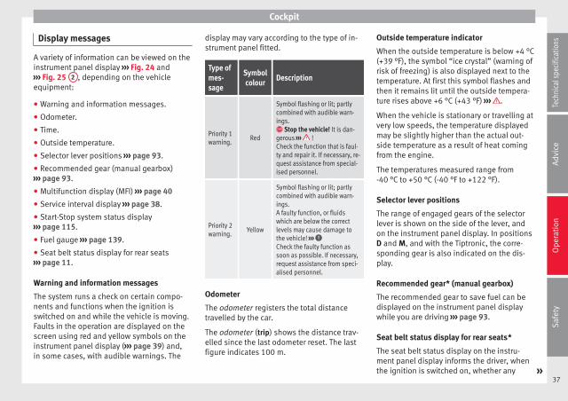
Cockpit
Display messages
A variety of information can be viewed on theinstrument panel display ››› Fig. 24 and››› Fig. 25 2 , depending on the vehicleequipment:
● Warning and information messages.
● Odometer.
● Time.
● Outside temperature.
● Selector lever positions ››› page 93.
● Recommended gear (manual gearbox)››› page 93.
● Multifunction display (MFI) ››› page 40
● Service interval display ››› page 38.
● Start-Stop system status display››› page 115.
● Fuel gauge ››› page 139.
● Seat belt status display for rear seats››› page 11.
Warning and information messages
The system runs a check on certain compo-nents and functions when the ignition isswitched on and while the vehicle is moving.Faults in the operation are displayed on thescreen using red and yellow symbols on theinstrument panel display (››› page 39) and,in some cases, with audible warnings. The
display may vary according to the type of in-strument panel fitted.
Type ofmes-sage
Symbolcolour
Description
Priority 1warning.
Red
Symbol flashing or lit; partlycombined with audible warn-ings. Stop the vehicle! It is dan-gerous ››› !Check the function that is faul-ty and repair it. If necessary, re-quest assistance from special-ised personnel.
Priority 2warning.
Yellow
Symbol flashing or lit; partlycombined with audible warn-ings.A faulty function, or fluidswhich are below the correctlevels may cause damage tothe vehicle! ››› Check the faulty function assoon as possible. If necessary,request assistance from speci-alised personnel.
Odometer
The odometer registers the total distancetravelled by the car.
The odometer (trip) shows the distance trav-elled since the last odometer reset. The lastfigure indicates 100 m.
Outside temperature indicator
When the outside temperature is below +4 °C(+39 °F), the symbol “ice crystal” (warning ofrisk of freezing) is also displayed next to thetemperature. At first this symbol flashes andthen it remains lit until the outside tempera-ture rises above +6 °C (+43 °F) ››› .
When the vehicle is stationary or travelling atvery low speeds, the temperature displayedmay be slightly higher than the actual out-side temperature as a result of heat comingfrom the engine.
The temperatures measured range from-40 °C to +50 °C (-40 °F to +122 °F).
Selector lever positions
The range of engaged gears of the selectorlever is shown on the side of the lever, andon the instrument panel display. In positionsD and M, and with the Tiptronic, the corre-sponding gear is also indicated on the dis-play.
Recommended gear* (manual gearbox)
The recommended gear to save fuel can bedisplayed on the instrument panel displaywhile you are driving ››› page 93.
Seat belt status display for rear seats*
The seat belt status display on the instru-ment panel display informs the driver, whenthe ignition is switched on, whether any »
37
Tech
nica
l spe
cific
atio
nsA
dvic
eO
pera
tion
Saf
ety

Operation
passengers in the rear seats have fastenedtheir seat belts ››› page 11.
Start-Stop system status display
The instrument panel display shows informa-tion on the current status ››› page 115.
WARNING
If the warning lamps are ignored, the vehiclemay stall in traffic, or may cause accidentsand severe injuries.
● Never ignore the warning lamps.
● Stop the vehicle safely as soon as possible.
● A faulty vehicle represents a risk of acci-dent for the driver and for other road users. Ifnecessary, switch on the hazard warninglamps and put out the warning triangle to ad-vise other drivers.
● Park the vehicle away from traffic and en-sure that no highly flammable materials areunder the vehicle that could come into con-tact with the exhaust system (e.g. dry grass,fuel).
WARNING
Even though outside temperatures are abovefreezing, some roads and bridges may be icy.
● At outside temperatures above +4°C(+39°F), even when the “ice crystal symbol”is not visible, there may still be patches of iceon the road.
● Never rely on the outside temperature indi-cator!
CAUTION
Failure to heed the warning lamps when theyappear may result in faults in the vehicle.
Note
● Different versions of the instrument panelare available and therefore the versions andinstructions on the display may vary.
● When several warnings are active at thesame time, the symbols are shown succes-sively for a few seconds and will stay on untilthe fault is rectified.
Service interval display
The inspection display appears on the instru-ment panel display ››› Fig. 24 or ››› Fig. 25 2 .
SEAT makes a difference between serviceswith engine oil change (Interval Service) andservices without engine oil change (Inspec-tion Service). The service interval display onlygives information for service dates which in-volve an engine oil change. The dates of theremaining services (e.g. the next InspectionService or change of brake fluid) are listed onthe label attached to the door strut, or in theMaintenance Programme.
The set service intervals have been specifiedwith the service dependent on time/distancetravelled.
Inspection reminder
If the inspection period is due to expireshortly, Inspection reminder appears whenstarting the ignition abbreviated to and awarning in km. The number of kilometresshown is the maximum number that may bedriven until the next service.
Service due
After the service date, an audible warning isgiven when the ignition is switched on andthe abbreviation displayed on the screenflashes for a few seconds.
Note
The service message disappears after a fewseconds, when the engine is started or whenOK is pressed on the windscreen wiper lever.
Note
In vehicles in which the battery has been dis-connected for a long period of time, it is notpossible to calculate the date of the nextservice. Therefore the service interval displaymay not be correct. In this case, bear in mindthe maximum service intervals permitted inthe ››› Booklet Maintenance Programme.
38

Cockpit
Control lamps
Control and warning lamps
The control and warning lamps are indicatorsof warnings, ››› , faults ››› or certain func-tions. Some control and warning lamps comeon when the ignition is switched on, andswitch off when the engine starts running, orwhile driving.
When certain control and warning lamps arelit, an audible warning is also heard.
Symbol Meaning ››› See
Handbrake applied.
››› page 89
Do not continue driving!The brake fluid level is too lowor there is a fault in the brakesystem.
it lights up: Do not continuedriving!The liquid coolant level is toolow,the engine liquid coolant tem-perature is too high orthere is a fault in the liquid cool-ant system.
››› page 150
flashes: engine coolant systemfaulty.
››› page 150
Do not continue driving!Engine oil pressure too low.
››› page 146
Symbol Meaning ››› See
lights up or flashes: Do notcontinue driving!Fault in the steering.
››› page 84
On the instrument panel: driveror passenger has not fastenedseat belt. ››› page
11
Instrument panel display: a pas-senger in the rear seats has fas-tened their seatbelt.
A passenger in the rear seatshas not fastened their seat belt.
››› page 11
Faulty generator.››› page 154
Vehicles with the Start-Stop sys-tem: it is necessary to start theengine manually.
››› page 115
flashes in addition to the rest ofthe segments of the fuel gauge:Fuel tank almost empty.
››› page 139
Symbol Meaning ››› See
flashes quickly: the City SafetyAssist system function* brakesautomatically or has braked au-tomatically. Or:flashes slowly: City Safety Assistfunction is not currently availa-ble. ››› page
110
The City Safety Assist* functionhas been connected manually. Itswitches off after 5 seconds.
flashes: The City Safety Assist*function has been manually dis-connected.
after the ignition is switched on:indication that the end of theperiod for an inspection to beperformed is approaching.
››› page 36
it lights up: ESC* faulty or dis-connected by the system. ALTER-NATIVELY:flashes: ESC* or ASR regulating.
››› page 89
it lights up: Traction Control faul-ty or switched off by the system.ALTERNATIVELY:flashes: Traction Control regula-tor operating.
ABS faulty or does not work.
Rear fog light switched on.››› page 55 »
39
Tech
nica
l spe
cific
atio
nsA
dvic
eO
pera
tion
Saf
ety

Operation
Symbol Meaning ››› See
lights up or flashes: fault in cata-lytic converter. ››› page
101 Fault in engine management.
lights up or flashes: fault in thesteering system.
››› page 84
Fuel tank almost empty.››› page 139
Fault in airbag system and seatbelt tensioners.
››› page 17
it lights up: the Start-Stop sys-tem is enabled. ALTERNATIVELY:flashes: the Start-Stop system isnot available. ››› page
115
The Start-Stop system is enabledbut the engine cannot be auto-matically stopped.
Tyre pressure* too low››› page 164
Left or right turn signal.
››› page 55
Hazard warning lights on.››› page 170
Cruise control operating.››› page 107
Main beam on or flasher on.››› page 55
The natural gas engine coolanttemperature is too low.
WARNING
If the warning lamps are ignored, the vehiclemay stall in traffic, or may cause accidentsand severe injuries.
● Never ignore the warning lamps.
● Stop the vehicle safely as soon as possible.
● Park the vehicle away from traffic and en-sure that there are no highly flammable ma-terials under the vehicle that could come intocontact with the exhaust system (e.g. drygrass, fuel).
● A faulty vehicle represents a risk of acci-dent for the driver and for other road users. Ifnecessary, switch on the hazard warninglamps and put out the warning triangle to ad-vise other drivers.
● Before opening the bonnet, switch off theengine and allow it to cool.
● In any vehicle, the engine compartment is ahazardous area and could cause severe inju-ries ››› page 143.
CAUTION
Failure to heed the warning lamps when theyappear may result in faults in the vehicle.
SEAT information system
Introduction
With the ignition switched on it is possible toaccess different messages via the display onthe instrument panel display.
The number of messages displayed on the in-strument panel display will vary according tothe vehicle electronics and equipment.
A specialised workshop will be able to pro-gramme or modify additional functions, ac-cording to the vehicle equipment. SEAT rec-ommends taking your car in for technicalservice.
WARNING
Any distraction may lead to an accident, withthe risk of injury.
● Do not consult the messages on the instru-ment panel screen when driving.
Note
On the screen of the SEAT Portable System(supplied by SEAT) ››› page 123 other func-tions of the vehicle can be seen.
40

Cockpit
Control functions of the instrumentpanel display
Fig. 26 Windscreen wiper lever: control but-tons.
Calling up options
● Switch the ignition on.
● If a message or vehicle symbol is dis-played, press OK/RESET (››› Fig. 26 A ).
● Press the top or bottom part of the rockerswitch ››› Fig. 26 B until the desired optionappears.
Multifunction display (MFI)
The multifunction display (MFI) has two auto-matic memories: 1 - Partial memory and 2 -Total memory. The selected memory will beshown in the lower right-hand corner of thedisplay.
With the ignition switched on, and memory 1 or2 displayed, briefly press OK to change fromone memory to another.
1
Trip memo-ry (for asingle jour-ney).
The memory stores the values for thejourney and the consumption fromthe moment the ignition is switchedon until it is switched off again.If the journey is broken for more than2 hours, the memory is automaticallyerased. If the journey is continued inless than 2 hours after the ignition isswitched off, the new data is added tothe data already stored in the memo-ry.
2Total mem-ory (for alljourneys).
The memory stores the values of anynumber of journeys, until it counts atotal of 19 hours and 59 minutes ofdriving, or 1999.9 km or miles of driv-ing, depending on the type of instru-ment panel fitted. On reaching eitherof these limits, the memory is auto-matically erased and starts to countfrom 0 again.
Possible displays
Menu Function
Time Current time in hours (h) and minutes(min).
Journey dura-tion
This indicates the hours (h) and mi-nutes (min) since the ignition wasswitched on.
Menu Function
Current fuelconsumption
The current fuel consumption displayoperates throughout the journey, inl/100 km; with the engine runningand the vehicle stopped, in l/hour.
Average fuelconsumption
After turning on the ignition, averagefuel consumption in litres/100 km willbe displayed after travelling about100 metres. Otherwise horizontallines are displayed. The value shownis updated approximately every 5 sec-onds.
Operatingrange
Approximate distance in km that canstill be travelled with the fuel remain-ing in the tank, assuming the samestyle of driving is maintained. This iscalculated using the current fuel con-sumption.
Distance cov-ered
Distance travelled, after ignition isswitched on, in km.
Average speed The average speed will be shown aftera distance of about 100 metres hasbeen travelled. Otherwise horizontallines are displayed. The value shownis updated approximately every 5 sec-onds.
Digital displayof speed
Current speed displayed digitally.
Liquid coolanttemperaturedigital display
Digital display of the current tempera-ture of the engine liquid coolant. »
41
Tech
nica
l spe
cific
atio
nsA
dvic
eO
pera
tion
Saf
ety

Operation
Menu Function
Warning at ---km/h
If the stored speed is exceeded (be-tween 30 - 250 km/h, or 18 -155 mph), an audible warning is giv-en together with a visual warning.
Changing between display modes
● Press the rocker switch in the windscreenwiper lever.
Storing a speed for the speed warning
● Select the display Speed warning at --- km/h.
● Press OK on the windscreen wiper lever tostore the current speed and switch off thewarning.
● In addition, set the required speed bypressing the rocker switch on the windscreenwiper lever or or buttons on the multi-function steering wheel for 5 seconds. Next,press OK again or wait a few seconds. Thespeed is stored and the warning activated.
● To switch off, press OK . The stored speed isdeleted.
Manually erasing memory 1 or 2
● Select the memory to be erased.
● Press and hold the eject button OK for ap-proximately 2 seconds.
Note
On the screen of the SEAT Portable System(supplied by SEAT) ››› page 123 other func-tions of the multifunction display can beseen.
42

Opening and closing
Opening and closing
Vehicle key set
Remote control vehicle key*
Fig. 27 Remote control key
Remote control key
With the vehicle key the vehicle may belocked or unlocked remotely ››› page 45.
The vehicle key includes an emitter and bat-tery. The receiver is in the interior of the vehi-cle. The range of the vehicle key with remotecontrol and new battery is several metresaround the vehicle.
If it is not possible to open or close the vehi-cle using the remote control key, this shouldbe re-synchronised ››› page 45 or the bat-tery changed ››› page 44.
Different keys belonging to the vehicle maybe used.
Folding the key shaft in and out
When the button is pressed ››› Fig. 27 A , thekey shaft is released and unfolds.
To fold it press the button and fold the keyshaft in until it locks in place.
Replacing a key
To obtain a spare key and other vehicle keys,the vehicle chassis number is required.
Each new key must contain a microchip andbe coded with the data from the vehicle elec-tronic immobiliser. A vehicle key will not workif it does not contain a microchip or the mi-crochip has not been encoded. This is alsotrue for keys cut for the vehicle.
The vehicle keys or new spare keys can beobtained from a SEAT dealership, a Special-ised workshop or approved key service quali-fied to create this kind of key.
New keys or spare keys must be synchron-ised before use ››› page 45.
WARNING
Careless or incorrect use of vehicle keys mayresult in severe injury and accident.
● Always take all the keys with you wheneveryou leave the vehicle. Children and unauthor-ised individuals could lock the doors or the
boot hatch, start the engine or turn on the ig-nition, activating electrical systems, the elec-tric windows, for example.
● Never leave children or disabled peoplealone in the car. They could be trapped in thecar in an emergency and will not be able toget themselves to safety. For example, de-pending on the time of the year, tempera-tures inside a locked and closed vehicle canbe extremely high or extremely low resultingin serious injuries and illness or even death,particularly for young children.
● Never remove the key from the ignition ifthe vehicle is in motion. The steering maylock and it will not be possible to turn thesteering wheel.
CAUTION
The remote control key contains electroniccomponents. Protect them from damage, im-pacts and humidity.
Note
● Only use the key button when you requirethe corresponding function. Pushing the but-ton unnecessarily could accidentally unlockthe vehicle or trigger the alarm. It is also pos-sible even when you are outside the radius ofaction.
● Remote control key operation can be great-ly influenced by overlapping radio signalsaround the vehicle working in the same range »
43
Tech
nica
l spe
cific
atio
nsA
dvic
eO
pera
tion
Saf
ety

Operation
of frequencies (for example, radiotransmitters, mobile telephones).
● Obstacles between the remote control andthe vehicle, bad weather conditions anddraining batteries can considerably reducethe range of the remote control.
● If the buttons of the vehicle key are press-ed ››› Fig. 27 or one of the central locking but-tons ››› page 45 is pressed repeatedly inquick succession, the central locking brieflydisconnects as protection against overload-ing. The vehicle is then unlocked. Lock it ifnecessary.
Vehicle mechanical key
Fig. 28 Vehicle mechanical key
The vehicle key set may include a mechanicalkey ››› Fig. 28.
Duplicate keys
To obtain a spare key and other vehicle keys,the vehicle chassis number is required.
Each new key must contain a microchip andbe coded with the data from the vehicle elec-tronic immobiliser. A vehicle key will not workif it does not contain a microchip or the mi-crochip has not been encoded. This is alsotrue for keys cut for the vehicle.
The vehicle keys or new spare keys can beobtained from a SEAT dealership, a special-ised workshop or an approved locksmithqualified to create them.
Control lamp on the vehicle key
Fig. 29 Control lamp on the vehicle key
When a button on the vehicle key is pressed,the control lamp flashes ››› Fig. 29 (arrow)once briefly. If the button is pressed andheld, the indicator blinks several times, for
example: for the convenience opening func-tion.
When the control lamp does not light uponpushing a button, the vehicle key batteriesmust be changed ››› page 44.
Changing the battery
Fig. 30 Vehicle key: battery compartment cov-er
Fig. 31 Vehicle key: removing the battery
44

Opening and closing
SEAT recommend having the batterieschanged in a specialised workshop.
The battery is located to the rear of the vehi-cle key, under a cover.
Changing the battery
● Unfold the vehicle key shaft ››› page 43.
● Remove the cover from the back of the ve-hicle key ››› Fig. 30 in the direction of the ar-row ››› .
● Extract the battery from the compartmentusing a suitable thin object ››› Fig. 31.
● Place the new battery in the compartment,pressing in the direction of the arrow asshown ››› Fig. 31 ››› .
● Fit the battery compartment cover, pressingin the direction of the arrow as shown››› Fig. 30 until it clicks into place.
CAUTION
● If the battery is not changed correctly, thevehicle key may be damaged.
● Use of unsuitable batteries may damagethe vehicle key. For this reason, always re-place the dead battery with another of thesame voltage, size and specifications.
● When fitting the battery, check that the po-larity is correct.
For the sake of the environment
Please dispose of your used batteries correct-ly and with respect for the environment.
Synchronising the vehicle key
If the button is pressed frequently outsideof the vehicle range, it is possible that the ve-hicle can no longer be locked or unlocked us-ing the key. In this case, the vehicle key mustbe synchronised once more as follows:
● Unfold the vehicle key shaft ››› page 43.
● Press the button on the vehicle key. Forthis, it must remain with the vehicle.
● Open the vehicle within one minute usingthe key shaft.
● Turn on the ignition using the vehicle key.The key has been synchronised.
● If necessary, fit the cap.
Central locking* and lockingsystem
Introduction
Central locking functions correctly when allthe doors and the rear lid are correctly shut.
If the driver door is open, the vehicle cannotbe locked with the key.
The battery of an unlocked vehicle parked fora long period (e.g. in a private garage) mayrun down and fail to start the motor.
WARNING
The incorrect use of the central locking sys-tem may cause serious injuries.
● The central locking system will lock alldoors. A vehicle locked from the inside canprevent any non-authorised individual fromopening the doors and accessing the vehicle.Nevertheless, in case of emergency or acci-dent, locked doors will complicate access tothe vehicle interior to help the passengers.
● Never leave children or disabled peoplealone in the vehicle. The central locking but-ton can be used to lock all the doors fromwithin. Therefore, passengers will be lockedinside the vehicle. Individuals locked in thevehicle can be exposed to very high or verylow temperatures.
● Depending on the time of the year, temper-atures inside a locked and closed vehicle canbe extremely high or extremely low resultingin serious injuries and illness or even death,particularly for young children.
● Never leave individuals locked in a closedand locked vehicle. In case of emergency,they may not be able to exit the vehicle bythemselves or get help.
45
Tech
nica
l spe
cific
atio
nsA
dvic
eO
pera
tion
Saf
ety

Operation
Description of the central lockingsystem
The central locking system allows all doorsand the rear lid to be locked and unlockedcentrally.
● From outside, using the vehicle key.
● From inside, by pushing the central lockingbutton ››› page 48.
The central locking system can be activatedor deactivated at a specialised workshop.
In case of a vehicle key fault or central lock-ing system fault, all doors can be locked orunlocked manually.
Locking the vehicle after the airbags havebeen deployed
If the airbags are deployed due to an acci-dent, the vehicle will be automatically andcompletely unlocked. Depending on theamount of damage, it can be locked follow-ing an accident in the following ways:
Function Necessary operations
Lock the vehicle,by pushing thecentral lockingbutton:
– Turn off the ignition and turn it onagain.– Push the central locking button .
Function Necessary operations
Use the key tolock the vehicle:
– Turn off the ignition and turn it onagain.OR: Remove the key from the igni-tion.– Open any door just once.– Lock the vehicle with the key.
Note
If the buttons of the vehicle key are pressed››› page 43 or one of the central locking but-tons ››› Fig. 34 is pressed repeatedly in shortsuccession, the central locking briefly discon-nects as protection against overloading. Inthis case, the vehicle remains unlocked forabout 30 seconds. If neither the door or theboot is opened during this time, the vehiclewill then automatically lock.
Locking and unlocking the vehiclefrom the exterior
Fig. 32 Buttons on the vehicle key
Fig. 33 Vehicle mechanical key
46

Opening and closing
Central locking
Function Handlingthe buttonson the vehi-cle ››› Fig. 32
Handling the vehiclekey ››› Fig. 32 in thelock cylinder or withthe vehicle mechani-cal key ››› Fig. 33.
Unlockingthe vehi-cle.
Press button .
Insert the vehicle key in-to the lock cylinder ofthe driver door and turnthe key in an anticlock-wise direction.
Lock thevehicle.
Press button .
Insert the vehicle key in-to the lock cylinder ofthe driver door and turnthe key in a clockwisedirection.
Unlockingthe rear lid.
Press button .
Insert the vehicle key in-to the lock cylinder ofthe driver door and turnthe key in an anticlock-wise direction.
Lockingthe rear lid.
Press button .
Insert the vehicle key in-to the lock cylinder ofthe driver door and turnthe key in a clockwisedirection.
Please note: depending on the operation ofthe central locking feature set by a special-ised workshop, in order to unlock all thedoors and the rear lid, press the button twice.
The vehicle key only locks and unlocks thevehicle if it is within range of the vehicle andif the battery has enough power.
● Upon locking the vehicle, all turn signalswill flash once in confirmation.
● Upon unlocking the vehicle, all turn signalswill flash twice in confirmation.
If the turn signals do not flash in confirma-tion, at least one of the doors or the rear lidhas been left unlocked.
If the driver door is open, the vehicle cannotbe locked with the key. If you unlock the vehi-cle without opening any doors or the rear lid,it will lock again automatically after a fewseconds. This function prevents the vehiclefrom remaining unlocked if the unlockingbutton is pressed by mistake.
Mechanical locking
FunctionUsing the vehicle's mechani-cal key ››› Fig. 33 in the lockcylinder
Locking the driv-er door manually.
To unlock, insert the vehicle key in-to the lock cylinder of the driverdoor and turn the key in an anti-clockwise direction.
To lock, insert the vehicle key intothe lock cylinder of the driver doorand turn the key in a clockwise di-rection.
FunctionUsing the vehicle's mechani-cal key ››› Fig. 33 in the lockcylinder
Locking and un-locking the rearlid.
To unlock, insert the vehicle key in-to the lock cylinder of the driverdoor and turn the key in an anti-clockwise direction.
To lock, insert the vehicle key intothe lock cylinder of the driver doorand turn the key in a clockwise di-rection.
If the driver's door is open, it cannot belocked with the vehicle key.
47
Tech
nica
l spe
cific
atio
nsA
dvic
eO
pera
tion
Saf
ety

Operation
Locking and unlocking the vehiclefrom the inside
Fig. 34 In the driver door: central locking but-ton
Fig. 35 In the passenger door: door handlefor mechanical locking.
Central locking
Push the button ››› Fig. 34:
Unlocking the vehicle.
Lock the vehicle.
The central locking button is still operativewhen the ignition is switched off.
If the vehicle has been locked with the vehi-cle key, the central locking button does notoperate.
Please note the following when you use thecentral locking button to lock your vehicle:
● The "Safe" security system will not activate››› page 48.
● It will not be possible to open the doors orthe rear lid from the outside this may offer ex-tra safety, when stopped at traffic lights forexample.
● The doors can be opened and unlocked in-dividually from the inside by pulling the in-side door handle. If necessary, pull the doorrelease lever twice.
● The driver door cannot be locked whenopen. This avoids locking the vehicle key in-side the vehicle when there is nobody inside.
Mechanical locking
The doors are locked by pressing the doorlever, so that the red mark becomes visible››› Fig. 35 1 .
To unlock a door, pull its corresponding doorlever.
If the vehicle becomes locked, take note ofthe following:
● The "Safe" security system will not activate››› page 48.
● It will not be possible to open the doorsfrom the outside, when stopped at trafficlights for example.
● The doors can be opened and unlocked in-dividually from the inside by pulling the in-side door handle.
● The driver door cannot be locked using thecentral locking system when it is still open.This avoids locking the vehicle key inside thevehicle when there is nobody inside.
“Safe” security system*
Function Necessary operations
Locks the vehicle withthe "Safe" security sys-tem.
Press the button once onthe vehicle key.
48
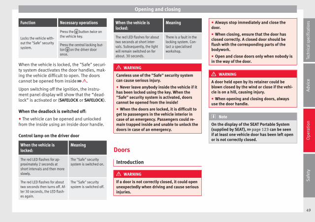
Opening and closing
Function Necessary operations
Locks the vehicle with-out the "Safe" securitysystem.
Press the button twice onthe vehicle key.
Press the central locking but-ton on the driver dooronce.
When the vehicle is locked, the "Safe" securi-ty system deactivates the door handles, mak-ing the vehicle difficult to open. The doorscannot be opened from inside ››› .
Upon switching off the ignition, the instru-ment panel display will show that the “dead-lock” is activated or (SAFELOCK or SAFELOCK).
When the deadlock is switched off:
● The vehicle can be opened and unlockedfrom the inside using an inside door handle.
Control lamp on the driver door
When the vehicle islocked:
Meaning
The red LED flashes for ap-proximately 2 seconds atshort intervals and then moreslowly.
The "Safe" securitysystem is switched on.
The red LED flashes for abouttwo seconds then turns off. Af-ter 30 seconds, the LED flash-es again.
The "Safe" securitysystem is switched off.
When the vehicle islocked:
Meaning
The red LED flashes for abouttwo seconds at short inter-vals. Subsequently, the lightwill remain switched on forabout. 30 seconds.
There is a fault in thelocking system. Con-tact a specialisedworkshop.
WARNING
Careless use of the "Safe" security systemcan cause serious injury.
● Never leave anybody inside the vehicle if ithas been locked using the key. When the"Safe" security system is activated, doorscannot be opened from the inside!
● When the doors are locked, it is difficult toget to passengers in the vehicle interior incase of an emergency. Passengers could re-main trapped inside and unable to unlock thedoors in case of an emergency.
Doors
Introduction
WARNING
If a door is not correctly closed, it could openunexpectedly when driving and cause seriousinjuries.
● Always stop immediately and close thedoor.
● When closing, ensure that the door hasclosed correctly. A closed door should beflush with the corresponding parts of thebodywork.
● Open and close doors only when nobody isin the way of the door.
WARNING
A door held open by its retainer could beblown closed by the wind or close if the vehi-cle is on a hill, causing injury.
● When opening and closing doors, alwaysuse the door handle.
Note
On the display of the SEAT Portable System(supplied by SEAT), ››› page 123 can be seenif at least one vehicle door has been left openor is not correctly closed.
49
Tech
nica
l spe
cific
atio
nsA
dvic
eO
pera
tion
Saf
ety

Operation
Childproof lock
Fig. 36 Childproof lock on the left hand sidedoor
The childproof lock prevents the rear doorsfrom being opened from the inside. This sys-tem prevents minors from opening a door ac-cidentally while the vehicle is running.
This function is independent of the vehicleelectronic opening and locking systems. Itonly affects rear doors. It can only be activa-ted and deactivated manually, as describedbelow:
Activating the childproof lock
– Unlock the vehicle and open the door inwhich you wish to activate the childprooflock.
– With the door open, rotate the groove inthe door using the ignition key, anti-clock-wise for the left-hand side doors ››› Fig. 36
and clockwise for the right-hand sidedoors.
Deactivating the childproof lock
– Unlock the vehicle and open the doorwhose childproof lock you want to deacti-vate.
– With the door open, rotate the groove inthe door using the ignition key, anti-clock-wise for the right-hand side doors, andclockwise for the left-hand side doors››› Fig. 36.
Once the childproof lock is activated, thedoor can only be opened from the outside.The childproof lock can be activated or deac-tivated by inserting the key in the groovewhen the door is open, as described above.
Rear lid
Introduction
WARNING
Careless and unsuitable locking, opening andclosing of the rear lid can cause accidentsand serious injury.
● Open and close the rear lid only when no-body is in the way.
● Do not close the rear lid by pushing it downwith your hand on the rear window. Thiscould break and cause injury.
● Ensure the rear lid is locked after closing,otherwise, it may open unexpectedly whiledriving. A closed rear lid should be flush withthe corresponding parts of the bodywork.
● Always keep the rear lid closed while driv-ing to avoid toxic gases entering the vehicleinterior.
● Do not open the rear lid when there is aload installed, for example a carrier system.Likewise, the boot hatch cannot be openedwhen a load is attached to it, for example bi-cycles. An open rear lid could close itself ifthere is an additional weight on it. If necessa-ry, press down on the rear lid and remove theload.
● Close and lock both the rear lid and all theother doors when you are not using the vehi-cle. Ensure that nobody remains inside thevehicle.
● Never allow children to play inside oraround the vehicle without supervision, espe-cially if the rear lid is open. Children couldenter the luggage compartment, close therear lid and become trapped. Depending onthe time of the year, temperatures inside alocked and closed vehicle can be extremelyhigh or extremely low resulting in serious in-juries and illness or even death, particularlyfor young children.
● Never leave children or disabled peoplealone in the vehicle. If the vehicle key or the
50

Opening and closing
central locking button is used, they may belocked in the vehicle.
CAUTION
Before opening the rear lid, ensure that thereis sufficient free space to open and close it,for example if you are in a garage.
Note
On the display of the Portable NavigationSystem (supplied by SEAT) ››› page 123 canbe seen if the rear lid has been left open or isnot correctly shut.
Opening the rear lid
Fig. 37 On the vehicle key: button to unlockand open the boot hatch.
If bicycles are attached to a rack on the boothatch, for example, in some cases, it may not
open automatically ››› . Remove the loadfrom the carrier and support the open rearlid.
Opening with central locking
● Press the button on the vehicle key››› Fig. 37 for about one second to unlock theboot hatch.
● OR: Press the button on the vehicle keyuntil the rear lid opens automatically severalcentimetres.
● Opening the rear lid with the button.
Opening with the vehicle mechanical key
● Insert the vehicle key into the lock cylinderof the driver door and turn the key in an anti-clockwise direction ››› page 45.
● Opening the rear lid with the button.
WARNING
Unsuitable or careless unlocking and openingof the rear lid could cause serious injuries.
● If there is a loaded luggage carrier on therear lid, it could be unlocked or open but notrecognised as such. An unlocked or open rearlid could open unexpectedly while driving.
Note
At outside temperatures of less than 0 °C(+32 °F), the pressurised gas struts cannotalways automatically lift the rear lid. In thiscase, open the rear lid manually.
Closing the rear lid
Fig. 38 Rear lid open: hand grip
Closing the rear lid
● Grab the handgrip inside the rear lid››› Fig. 38 (arrow).
● Push the rear lid downwards until it locksinto place in the lock.
● Ensure that it is correctly closed by pullingon it firmly.
Locking the rear lid with central locking*
If you unlock the vehicle without opening anydoors or the rear lid, it will lock again auto-matically after about 30 seconds. This func-tion prevents the vehicle from remaining un-locked if the unlocking button is pressed bymistake.
Locking is only possible when the rear lid iscorrectly and fully closed. »
51
Tech
nica
l spe
cific
atio
nsA
dvic
eO
pera
tion
Saf
ety

Operation
● The rear lid is also locked by a central lock-ing.
● If the vehicle rear lid is locked or unlockedusing the button, when it is closed oncemore it will lock automatically.
● A closed but not locked rear lid will lock au-tomatically at a speed above about 9 km/h(6 mph).
Locking the rear lid with the vehiclemechanical key
Locking is only possible when the rear lid iscorrectly and fully closed.
● Insert the vehicle key into the lock cylinderof the driver door and turn the key in a clock-wise direction ››› page 45.
WARNING
Unsuitable or careless closing and locking ofthe rear lid could cause serious injuries.
● Never allow children to play inside oraround the vehicle without supervision, espe-cially if the rear lid is open. Children couldenter the luggage compartment, close therear lid and become trapped. A locked vehiclecan be subjected to extremely high and lowtemperatures, depending on the time of year,thus causing serious injuries/illness andeven death.
Note
Before closing the rear lid, make sure that thekey has not been left inside the luggage com-partment.
Electric windows
Opening and closing the electricwindows
Fig. 39 In the driver door: electric windowsbutton
Opening and closing the windows
Function Necessary operations
Opening: Press button .
Closing: Pull the switch .
WARNING
Careless use of the electric windows cancause serious injury.
● Only operate the electric windows whennobody is in the way.
● Never leave children or disabled peoplealone in the vehicle if the doors are to belocked. The windows cannot be opened incase of an emergency.
● Always take all the keys with you wheneveryou leave the vehicle. After turning off the ig-nition, the windows can be opened andclosed for a short time using the buttons onthe door as long as the driver door or passen-ger side door is not open.
CAUTION
When the windows are open, rain can enterthe vehicle, dampening the interior equip-ment and causing damage to the vehicle.
52

Opening and closing
Side-opening rear windows
Fig. 40 Lever to open and close the rear win-dow
Opening
Pull the release lever in the direction of arrowA and press outward until the lever engag-
es.
Closing
Pull the release lever in the direction of arrowB and then press the lever backward until it
engages.
Sliding/tilting electricpanoramic sunroof
Introduction
WARNING
If the sliding/tilting electric panoramic sun-roof is used negligently or without payingdue attention, it can cause serious injury.
● The sliding/tilting sunroof should only beopened or closed when no one is blocking itspath.
● After switching off, it is still possible toopen or close the sliding/tilting sunroof dur-ing a short space of time provided that nei-ther the driver nor passenger door is opened.
CAUTION
● To prevent damage, when there are wintertemperatures any ice or snow that there maybe on the roof of the vehicle must be removedbefore opening or raising the sliding/tiltingelectric panoramic sunroof.
● Before leaving the vehicle or in the case ofheavy rain, the sliding/tilting sunroof mustalways be closed. With the sliding/tiltingsunroof open or raised, water can enter thepassenger compartment and can cause con-siderable damage to the electrical system. Asa result, other damage can occur in the vehi-cle.
● In the case of heavy rain, if the sliding/tilt-ing sunroof is open, the interior equipment ofthe vehicle may get wet, destroying the seatheating and damaging the electrical systemof the vehicle.
Note
● Leaves and other loose objects that land inthe guides of the sliding/tilting sunroofshould be removed periodically by hand orusing a vacuum cleaner.
● If the sliding/tilting sunroof does not workcorrectly, the anti-trap function will not workeither. In this case, you should take the vehi-cle to a specialised workshop.
53
Tech
nica
l spe
cific
atio
nsA
dvic
eO
pera
tion
Saf
ety

Operation
Opening and closing thesliding/tilting electric panoramicsunroof
Fig. 41 In the interior roof: turn the knob toopen and close
Fig. 42 In the interior roof: turn the knob toraise and to close the sunroof
To raise the sliding/tilting sunroof, the knobmust be in the basic position 1 .
Function ››› Fig. 41or››› Fig. 42
Action
Fully open-ing the slid-ing sunroof:
3
turn the know beyondposition 2 and hold it inthat position until thesunroof reaches the re-quired position.
Put the slid-ing sunroofin conven-ience posi-tion:
2
Turn the knob to the re-quired position.
To set the in-termediateposition:
2 to 1
Fully closingthe slidingsunroof:
1
To raise thetilting sun-roof com-pletely:
4briefly press the rear partof the knob.
To stop auto-matic opera-tion:
4 or 5Press or pull the knobagain briefly.
To closecompletely:
5briefly pull the rear partof the knob.
The sliding/tilting sunroof only works whenswitched on. After switching off, it is still pos-sible to open or close the sliding/tilting sun-roof during a short space of time provided
that neither the driver nor passenger door isopened.
All operations are interrupted when the rotaryknob is actuated.
If it were not possible to close the sliding/tilt-ing sunroof electrically, it would need to beclosed manually. It is not possible to do anemergency close of the sliding/tilting sun-roof without removing components of the ve-hicle. In such a case, obtain professional as-sistance.
Sliding blind
With the roof grab handle situated in the rearpart of the roof opening, it is possible tomove the sliding blind to the required posi-tion.
Note
The convenience position permits sufficientventilation with a level of sound produced bylow wind.
Anti-trap function of thesliding/tilting electric panoramicsunroof
The anti-trap function can reduce the risk ofinjury when closing the sliding/tilting electricpanoramic sunroof ››› . If the sliding/tilting
54

Lights and visibility
sunroof encounters resistance or an obstaclewhen closing, it will immediately reopen.
● Check why the sliding/tilting sunroof hasnot closed.
● Try to close it again.
● If it is still not possible to close it due to anobstacle or resistance, it will remain in thecorresponding position. Close it without theanti-trap function.
Closing the sliding/tilting electric panoramicsunroof without the anti-trap function
● Within about 5 seconds of activating theanti-trap function, pull knob ››› Fig. 42 5 un-til the sliding/tilting sunroof is fully closed.
● As such, the sliding/tilting sunroof willclose without the anti-trap function!
● If the sunroof still cannot be closed, visit aspecialised workshop.
If the knob is released during the closing op-eration, the sliding/tilting electric panoramicsunroof opens automatically.
WARNING
Closing the sliding/tilting electric panoramicsunroof without the anti-trap function can re-sult in serious injury.
● The sliding/tilting sunroof should alwaysbe closed carefully.
● No person should ever remain in the way ofthe sliding/tilting sunroof, especially whenclosing without the anti-trap function.
● The anti-trap function does not prevent fin-gers or other parts of the body from becom-ing trapped against the roof frame and inju-ries occurring.
Lights and visibility
Lights
Introduction
The legal requirements regarding the use ofvehicle lights in each country must be ob-served.
The driver is personally responsible for thecorrect use and adjustment of the lights in allsituations.
WARNING
If the headlights are set too high and themain beam is not used correctly, there is arisk of dazzling or distracting other roadusers. This could result in a serious accident.
● Always make sure that the headlights arecorrectly adjusted.
● Never use the main beam or flashed head-lamps as this could dazzle other drivers.
Control lamps
It lightsup
Possible cause Solution
Rear fog light switchedon.
››› page 56 »
55
Tech
nica
l spe
cific
atio
nsA
dvic
eO
pera
tion
Saf
ety

Operation
It lightsup
Possible cause Solution
Front fog lights switch-ed on
››› page 56
Left or right turn sig-nal.The control lamp flash-es twice as fast when avehicle turn signal isfaulty.
If necessary,check the vehi-cle's lights.
Main beam on orflasher on.
››› page 57
Several warning and control lamps light upfor a few seconds when the ignition is switch-ed on, signalling that the function is beingverified. They will switch off after a few sec-onds.
WARNING
Observe the safety warnings ››› in Controland warning lamps on page 40.
Turning on and off lights
Fig. 43 Next to the steering wheel: diagramof some of the types of light switch
The legal requirements regarding the use ofvehicle lights in each country must be ob-served.
Turn the light switch to the required position››› Fig. 43:
When the ignition isswitched off
When the ignitionis on
Fog lights, dippedbeam and side lightsoff.
Lights off, daytimedriving light on.
Side light on. Side light on.
Dipped beam off; ifnecessary, the sidelight comes on for atime.
Dipped beam switchedon.
Fog lights*
The control lamp appears on the fog lightscontrol connected.
● Switching on the front fog lights : Turnthe switch to position or pull out to thefirst stop.
● Switching on the rear fog light : turn thelight switch to position or pull out tothe maximum.
● To switch off the fog lights, press the lightswitch or turn it to position .
Audible warnings to advise the driver thatthe lights have not been switched off
If the key is not in the ignition and the driverdoor is open, an audible warning signal isheard in the following cases: this is a remind-er to turn off the lights.
● When the light switch is in position .
● When the light switch is in position .
WARNING
The side lights or daytime driving lights arenot bright enough to illuminate the roadahead and to ensure that other road users areable to see you.
● Always use your dipped beam head lights ifit is raining or if visibility is poor.
56

Lights and visibility
Lights and visibility: functions
Parking light remains on both sides
If when switching off the ignition, the lightcontrol remains in the position and the ve-hicle is closed from outside, both headlights,in addition to the side lights and the rearlights will light up.
Daytime driving light
The daytime driving light consists of individu-al lights in the front headlamps.
When the daytime driving light is switchedon, only the individual lights come on ››› .
The daytime lights are switched on each timethe ignition is turned on if the light switch isin position .
Switching the daytime driving light on andoff
To switch the daytime driving light on or off,it is necessary to fit or remove the corre-sponding fuse. Ask for professional assis-tance for this.
WARNING
If the road is not well-lit and the vehicle isnot clearly visible to other drivers, an acci-dent may occur.
● Never use the daytime driving light if theroad is not well-lit as a result of the weather
conditions and poor visibility. The daytimedriving lights are not bright enough to illumi-nate the road ahead and to ensure that otherroad users are able to see you.
● The rear lights do not come on with thedaytime driving light. A vehicle which doesnot have the rear lights on may not be visibleto other drivers in the darkness, if it is rain-ing or in conditions of poor visibility.
Note
The headlights, rear lights and turn signalsmay mist up temporarily on the inside in coolor damp weather. This is normal and in noway effects the useful life of the vehicle light-ing system.
Turn signal and main beam lever
Fig. 44 Turn signal and main beam lever intheir initial position
Move the lever to the required position:
Right turn signal.
Left turn signal.
Switching on main beam ››› . When themain beam headlights are switched on,the warning lamp is switched on in theinstrument panel.
Switch on the flasher or switch off themain beam headlights. The flashed beamcomes on if the lever is pressed. Thewarning lamp will light up during thisprocess.
Push the lever all the way down to turn offthe corresponding function.
Convenience turn signals
For the convenience turn signals, move thelever as far as possible upwards or down-wards and release the lever. The turn signalwill flash 3 times.
The convenience indicators can be deactiva-ted at a Specialised workshop.
WARNING
Incorrect use of the headlights may cause ac-cidents and serious injury, as the main beammay distract or dazzle other drivers. »
1
2
3
4
57
Tech
nica
l spe
cific
atio
nsA
dvic
eO
pera
tion
Saf
ety

Operation
Note
● The turn signal only works when the igni-tion is switched on. The hazard warninglights also work when the ignition is switch-ed off ››› page 170.
● If any of both turn signals fails, the warninglamp will start flashing twice faster than nor-mal.
● The main beam headlights can only beswitched on if the dipped beam headlightsare already on.
Adjusting the headlights
In those countries where vehicles drive onthe other side of the road to the home coun-try, the asymmetric dipped beam may dazzledrivers of oncoming vehicles.
For this reason, stickers may be needed tocover the headlights when driving abroad.For further information, please refer to a spe-cialised workshop. SEAT recommends visitinga technical service.
Note
The use of stickers to cover headlights is onlypermitted over a short period. To modify thedirection of the headlamps more permanent-ly, please take the vehicle to a specialisedworkshop. SEAT recommends taking your carin for technical service.
Headlight range control, lighting ofinstruments and controls
Fig. 45 Next to the steering wheel: Headlightrange control
Headlamp height adjustment
The headlight range control ››› Fig. 45 ismodified according to the value of the head-light beam and the vehicle load status. Thisoffers the driver optimum visibility and theheadlights do not dazzle oncoming drivers››› .
The headlights can only be adjusted whenthe dipped beam is switched on.
To reset, turn switch ››› Fig. 45:
Value Vehicle load statusa)
–Two front occupants, luggage compart-ment empty
To reset, turn switch ››› Fig. 45:
Value Vehicle load statusa)
1All seats occupied, luggage compartmentempty
2All seats occupied, luggage compartmentfull
3 Driver only, luggage compartment full
a) If the vehicle load does not correspond to those shown in thetable, it is possible to select intermediary positions.
Instrument and switch lighting
When the side lights or dipped beam head-lights are switched on, the lighting for instru-ments and controls lights up at a constantbrightness.
WARNING
Heavy objects in the vehicle may mean thatthe headlights dazzle and distract other driv-ers. This could result in a serious accident.
● Adjust the light beam to the vehicle loadstatus so that it does not blind other drivers.
Reading light
But-ton/Switch
Function
Switching off the reading light.
58
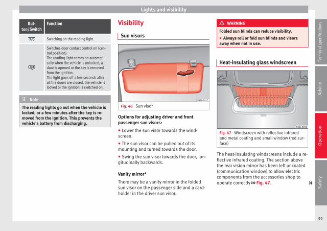
Lights and visibility
But-ton/Switch
Function
Switching on the reading light.
Switches door contact control on (cen-tral position).The reading light comes on automati-cally when the vehicle is unlocked, adoor is opened or the key is removedfrom the ignition.The light goes off a few seconds afterall the doors are closed, the vehicle islocked or the ignition is switched on.
Note
The reading lights go out when the vehicle islocked, or a few minutes after the key is re-moved from the ignition. This prevents thevehicle's battery from discharging.
Visibility
Sun visors
Fig. 46 Sun visor
Options for adjusting driver and frontpassenger sun visors:
● Lower the sun visor towards the wind-screen.
● The sun visor can be pulled out of itsmounting and turned towards the door.
● Swing the sun visor towards the door, lon-gitudinally backwards.
Vanity mirror*
There may be a vanity mirror in the foldedsun visor on the passenger side and a card-holder in the driver sun visor.
WARNING
Folded sun blinds can reduce visibility.
● Always roll or fold sun blinds and visorsaway when not in use.
Heat-insulating glass windscreen
Fig. 47 Windscreen with reflective infraredand metal coating and small window (red sur-face)
The heat-insulating windscreens include a re-flective infrared coating. The section abovethe rear vision mirror has been left uncoated(communication window) to allow electriccomponents from the accessories shop tooperate correctly ››› Fig. 47. »
59
Tech
nica
l spe
cific
atio
nsA
dvic
eO
pera
tion
Saf
ety

Operation
CAUTION
When the uncoated surface is covered or hasa sticker on the interior or exterior, malfunc-tions in the electronic components may oc-cur. Never cover the uncoated surface on theinterior or exterior.
Windscreen wiper and rearwindow wiper systems
Introduction
WARNING
Water from the windscreen washer water bot-tle may freeze on the windscreen if it doesnot contain enough anti-freeze, reducing for-ward visibility.
● In winter, ensure the windscreen washercontains enough anti-freeze.
● In cold conditions, you should not use thewash/wipe system unless you have warmedthe windscreen with the ventilation system.The antifreeze could freeze on the windscreenand reduce visibility.
WARNING
Worn or dirty wiper blades reduce visibilityand increase the risk of accident and seriousinjury.
● Always replace damaged or worn blades orblades which do not clean the windscreencorrectly.
CAUTION
In icy conditions, always check that the wiperblades are not frozen to the glass before us-ing the wipers for the first time. In coldweather, it may help to leave the vehicleparked with the wipers in service position››› page 61.
Window wiper lever
Fig. 48 Operating the windscreen wiper andrear wiper
Move the lever to the required position ››› :
0 Windscreen wiper off.
1 Windscreen interval wipe.
Move the lever to the required position ››› :
2 Slow wipe.
3 Continuous wipe.
4 Brief wipe - short wipe. Hold the leverdown for more time to increase the wipefrequency.
5 Automatic wipe for cleaning wind-screens with the lever up.
6 Interval wipe for rear window. The wiperwill wipe the window approximately ev-ery six seconds.
7 Automatic wipe for cleaning rear win-dows with the lever pressed.
CAUTION
If the ignition is switched off while the wind-screen wipers are on, the windscreen wiperscarry on wiping at the same level when theignition is switched back on. Ice, snow andother obstacles may damage the windscreenwiper and the respective motor.
● If necessary, remove snow and ice from thewindscreen wipers before starting your jour-ney.
● Carefully lift the frozen windscreen wipersfrom the glass. SEAT recommends a de-icerspray for this operation.
60

Lights and visibility
Note
● The windscreen wipers will only work whenthe ignition is switched on.
● The interval wipe speed varies according tothe vehicle speed. The faster the vehicle ismoving, the more often the windscreen iscleaned.
● The rear wiper is automatically switched onwhen the windscreen wiper is on and the caris in reverse gear.
Windscreen wiper functions
Windscreen wiper performance in different sit-uations
If the vehicle is at astandstill
The activated position provision-ally changes to the previous posi-tion.
For intermittent wip-ers
Intervals between wipes dependon the vehicle's speed. The high-er the vehicle speed the shorterthe intervals.
Note
The wiper will try to wipe away any obstaclesthat are on the windscreen. The wiper willstop moving if the obstacle blocks its path.Remove the obstacle and switch the wiperback on again.
Windscreen wipers service position
Fig. 49 Wipers in service position
The wiper arms can be raised when the wip-ers are in service position ››› Fig. 49. To placethe windscreen wipers in the service posi-tion, proceed as follows:
● The bonnet must be closed ››› page 143.
● Switch the ignition on and off.
● Press the windscreen wiper lever down-wards briefly ››› Fig. 48 4 .
Before driving, always lower the wiper arms.When the ignition is switched on, the wind-screen wiper arms return to their initial posi-tion upon activating the windscreen wiperlever.
Lifting and returning windscreen wiper arms
● Place the wiper arms in the service position››› .
● Only hold the wiper arms at the pointwhere the blade is fixed.
CAUTION
● To prevent damage to the bonnet and thewiper arms, only leave them in the serviceposition.
● Before driving, always lower the wiperarms.
Rear vision mirror
Rear vision mirror
Fig. 50 Manual anti-dazzle function for rearvision mirror
The driver should always adjust the rear vi-sion mirror to permit adequate visibilitythrough the rear window. »
61
Tech
nica
l spe
cific
atio
nsA
dvic
eO
pera
tion
Saf
ety

Operation
Manual anti-dazzle function for interior rearvision mirror
● Basic position: point the lever at the bot-tom of the mirror forwards.
● Pull the lever to the back to select the anti-dazzle function ››› Fig. 50.
Exterior mirrors
Fig. 51 In the front doors: button to adjustthe mechanical exterior rear vision mirror
Fig. 52 In the driver door: rotary control forthe exterior electric mirrors
Adjust the exterior mirrors by pressing theadjust button ››› Fig. 51 or the rotary control*››› Fig. 52.
Turn the rotary control ››› Fig. 52 to the requiredposition:
Switch on the exterior mirror heating
Adjust the left-hand exterior mirror by turningthe knob forward, backward, to the right or tothe left.
Zero position. Exterior mirror heating switchedoff, it is not possible to adjust the exterior mir-rors.
Adjust the right-hand exterior mirror by turningthe knob forward, backward, to the right or tothe left.
Folding in the exterior mirrors and returningthem to their original position is possiblethrough a mechanical system. Carefully fold
the exterior rear vision mirror casing towardsthe side window or pull it away from the win-dow until it clicks into place.
WARNING
Fold and unfold the exterior mirror, takingcare to avoid injuries.
● Only fold or unfold the exterior mirror whenthere is no-one in the way of the mirror.
● When moving the mirror, take care not totrap fingers between the mirror and the mir-ror bracket.
WARNING
Failure to correctly estimate the distance ofthe vehicle behind could lead to serious acci-dent.
● Rear-view convex or aspheric mirrors in-crease the field of vision, however objects ap-pear smaller and further away in the mirrors.
● The use of these mirrors to estimate thedistance to the next vehicle when changinglane is imprecise and could result in seriousaccident.
● If possible, use the rear vision mirror to es-timate distances to vehicles behind you or inother circumstances.
● Make sure that the rear visibility is ade-quate.
62

Seats and head restraints
For the sake of the environment
The exterior mirror heating should be switch-ed off when it is no longer needed. Other-wise, it is an unnecessary fuel waste.
Note
In the event of faults, the electric exteriormirrors can be adjusted manually by pressingthe edge of the mirror surface.
Seats and head restraints
Adjusting the seat and headrestraints
Manual seat adjustment
Fig. 53 Front left seat controls
The controls are mirrored for the front right-hand seat.
The front seat head restraints are integratedin the backrests and adjusting them is notpossible.
Fig. 53
Function Necessary operations
1
Moving the headrestraint back-wards or for-wards.
Pull the lever and move theseat forwards. The frontseat must be engagedwhen the lever is released!
Fig. 53
Function Necessary operations
2Adjusting theseat height.
Pull the lever up or pushdown (several times if nec-essary) from its home posi-tion.
3
3 doors: Easy En-try + adjustableseat angle func-tion. 5 doors: only ad-justable seat an-gle function.
Adjust: pull the lever andadjust the backrest seatangle until you reach thedesired position. The seatbackrest must be engaged.
To fold: Pull the lever andtilt the backrest. At thesame time, move the seatforward.
To tilt open: Move the seatback until the catch engag-es. Pull the lever and tiltopen the backrest. Thebackrest must engage inthe upright position.
63
Tech
nica
l spe
cific
atio
nsA
dvic
eO
pera
tion
Saf
ety

Operation
Removing and installing the rear headrestraints
Fig. 54 Removing the rear head restraint
The rear seats are equipped with a head re-straint.
Removing the rear head restraint.
● Unlock the seat backrest and fold it forward››› page 73.
● Push the head restraint up as far as it willgo ››› .
● Pull the head restraint out of the fittingwithout releasing the button ››› Fig. 54 1 .
● Fold the backrest of the rear seat backwardagain until it is engaged.
● Safely store the removed head restraints.
Removing the rear head restraint.
● Unlock the seat backrest and fold it forward››› page 73.
● Insert the head restraint into the guides onthe seat backrest.
● Push the head restraint down as far as itwill go while pressing button 1 .
● Fold the backrest of the rear seat backwardagain until it is engaged.
● Adjust the head restraint to the correct po-sition ››› page 9.
WARNING
Travelling with the head restraints removedor improperly adjusted increases the risk ofsevere or fatal injuries in the event of acci-dents and sudden braking or manoeuvres.
● Always fit and adjust the head restraintproperly whenever a person is occupying aseat.
● Refit any removed head restraints immedi-ately so that passengers are properly protec-ted.
CAUTION
When removing and fitting the head restraint,make sure it does not hit the headliner of thevehicle or the front seat backrest. Otherwise,the interior roof and other parts of the vehiclecould be damaged.
Seat functions
Seat heating*
Fig. 55 In the centre console: Front seatsheating switch
The front seat cushions can be heated electri-cally when the ignition is switched on.
Switch off seat heating if there is nobody inthe seat.
Function Action ››› Fig. 55
Activate Press button . Seat heating isswitched on fully. All warning sig-nals light up.
Adjusting theheating output
Press the button again to adjustthe desired heat.
Deactivating Keep pressing button until all ofthe lights are switched off.
64

Transport and practical equipment
WARNING
People whose pain and temperature thresh-old has been affected by some kind of medi-cine, paraplegia or chronic illness (e.g. diabe-tes) may sustain burns to the back, buttocksand legs from using the seat heaters thatmay lead to a long healing process or thatmay never completely heal. Seek medical ad-vice if you have doubts regarding your health.
● People with limited pain and temperaturethresholds must never use seat heating.
WARNING
Inappropriate use of the seat functions cancause severe injuries.
● Assume the proper sitting position beforeyour trip and remain in it throughout. This al-so applies to the other occupants.
● Keep hands, fingers, feet and other limbsaway from the seat operating and adjustmentradius.
CAUTION
● To avoid damaging the heating elements ofthe seat heaters, please do not kneel on theseat or apply sharp pressure to a single pointon the seat cushion or backrest.
● Liquids, sharp objects and insulating mate-rials on the seat could damage the seat heat-ing.
● In the event of smells, switch off the seatheating immediately and have the unit in-spected by a specialised workshop.
For the sake of the environment
The seat heating should remain on only whenneeded. Otherwise, it is an unnecessary fuelwaste.
Transport and practicalequipment
Transporting objects
Introduction
Always transport heavy loads in the luggagecompartment and place the seat backs in avertical position. Never overload the vehicle.Both the carrying capacity as well as the dis-tribution of the load in the vehicle affect driv-ing behaviour and braking ability ››› .
WARNING
Unsecured or incorrectly secured objects cancause serious injury in case of a sudden ma-noeuvring or breaking or in case of an acci-dent. This is especially true when objects arestruck by a detonating airbag and firedthrough the vehicle interior. To reduce therisks, please note the following:
● Secure all objects in the vehicle. Alwayskeep equipment and heavy objects in the lug-gage compartment.
● Always secure objects with suitable rope orslings so that they cannot enter the deploy-ment areas around the frontal or side airbagsin case of sudden braking or an accident.
● Always ensure that objects inside the vehi-cle cannot move into the deployment area ofthe bags while driving. »
65
Tech
nica
l spe
cific
atio
nsA
dvic
eO
pera
tion
Saf
ety

Operation
● While driving, always keep object compart-ments closed.
● Remove all objects from the front passen-ger seat when it is folded down. When theseat backrest is folded down, it presses onsmall and light objects and these are detec-ted by the weight sensor on the seat; thissends false information to the airbag controlunit.
● While the backrest of the front passengerseat is folded, the frontal airbag must remaindisconnected and the PASSENGER AIRBAGOFF light on.
● Objects secured in the vehicle should neverbe placed in such a way as to make passen-gers sit in an incorrect position.
● If secured objects occupy a seat, this seatshould not be occupied or used by anyone.
WARNING
The driving behaviour and braking abilitychange when transporting heavy and largeobjects.
● Adjust your speed and driving style to visi-bility, road, traffic and weather conditions.
● Accelerate gently and carefully.
● Avoid sudden braking and manoeuvres.
● Brake early.
Transporting a load
Secure all objects in the vehicle
● Distribute the load throughout the vehicleand on the roof as uniformly as possible.
● Transport heavy objects as far forward aspossible in the luggage compartment andlock the seat backs in the vertical position.
● Check the headlight adjustment››› page 55.
● Use the suitable tyre pressure according tothe load being transported. Read the tire in-flation information label ››› page 158.
CAUTION
Objects on the shelf could chafe against thewires of the heating element in the heatedrear window and cause damage.
Note
Please refer to the notes on loading the roofcarrier ››› page 77.
Driving with the rear lid open
Driving with the rear lid open creates an addi-tional risk. Secure all objects and secure therear lid correctly and take all measures possi-ble to reduce toxic gases from entering thevehicle.
WARNING
Driving with the rear lid unlocked or opencould cause serious injuries.
● Always drive with the rear lid closed.
● Secure all objects in the vehicle. Looseitems could fall out of the vehicle and injureother road users or damage other vehicles.
● Drive particularly carefully and thinkahead.
● Avoid sudden manoeuvres and braking giv-en that this could cause an uncontrolledmovement of the open rear lid.
● When transporting objects that protrudeout of the luggage compartment, indicatethem suitably. Observe legal requirements.
● If objects must project out of the luggagecompartment, the rear lid must never be usedto “secure” or “attach” objects.
● If a baggage rack is fitted on the rear lid, itshould be removed before travelling with therear lid open.
WARNING
Toxic gases may enter the vehicle interiorwhen the rear lid is open. This could causeloss of consciousness, carbon monoxide poi-soning, serious injury and accidents.
● To avoid toxic gases entering the vehicle al-ways drive with the rear lid closed.
66

Transport and practical equipment
● In exceptional circumstances, if you mustdrive with the rear lid open, observe the fol-lowing to reduce the entry of toxic gasesinside the vehicle:
– Close all windows.
– Disable air recirculation mode.
– Open all of the air outlets on the instru-ment panel.
– Switch on the blower to maximum.
CAUTION
An open boot hatch changes the length andheight of the vehicle.
Driving a loaded vehicle
For the best handling when driving a loadedvehicle, note the following:
● Secure all objects ››› page 66.
● Accelerate gently and carefully.
● Avoid sudden braking and manoeuvres.
● Brake early.
● If necessary, read the instructions for driv-ing with a roof carrier system ››› page 77.
WARNING
A sliding load could considerably affect thestability and safety of the vehicle resulting inan accident with serious consequences.
● Secure loads correctly so they do not move.
● When transporting heavy objects, use suit-able ropes or straps.
● Lock the seat backs in vertical position.
Practical equipment
Introduction
Storage compartments must only be used tostore light or small objects.
WARNING
In the event of sudden braking movements orturns, loose objects may be thrown aroundthe vehicle interior. This could cause seriousinjuries to passengers and cause the driver tolose control of the vehicle.
● Do not transport animals or place hard,heavy or sharp objects inside the vehicle in:open storage compartments, dash panel, rearshelf, items of clothing or bags.
● While driving, always keep object compart-ments closed.
WARNING
Objects falling into the driver's footwell couldprevent use of the pedals. This could lead thedriver to lose control of the vehicle, increas-ing the risk of a serious accident.
● Make sure the pedals can be used at alltimes, with no objects rolling underneaththem.
● The floor mat should always be secured tothe floor.
● Never place other mats or rugs on top ofthe original mat supplied by the factory.
● Make sure that no objects can fall into thedriver's footwell while the vehicle is in mo-tion.
CAUTION
● Objects on the shelf could chafe againstthe wires of the heating element in the heat-ed rear window and cause damage.
● Do not keep temperature-sensitive objects,food or medicines inside the vehicle. Heatand cold could damage them or render themuseless.
● Light-transparent objects placed inside thevehicle, such as lenses, magnifying glassesor transparent suction caps on the windows,may concentrate the sun's rays and causedamage to the vehicle.
Note
The ventilating slits between the heated rearwindow and the rear shelf must not be cov-ered so that used air can escape from the ve-hicle.
67
Tech
nica
l spe
cific
atio
nsA
dvic
eO
pera
tion
Saf
ety

Operation
Storage compartment on the driverside
Fig. 56 On the driver side: storage compart-ment
There may be a storage compartment on thedriver side.
Compartment on the centre console
Fig. 57 In the front part of the centre console:storage compartment
The storage compartment ››› Fig. 57 may beused as a drink holder ››› page 71 or as anashtray* ››› page 71 or to store small ob-jects.
Note
A 12 volt electrical socket ››› page 72 can befound in the storage compartment.
Storage compartment with cover onthe passenger side*
Fig. 58 Storage compartment with cover onthe passenger side
There may be a storage compartment withcover on the passenger side.
68

Transport and practical equipment
Opening and closing the storagecompartment cover
Pull the lever to open ››› Fig. 58 1 .
To close, press the cover upwards until itclicks into place.
Sunglasses storage compartment.
Sunglasses can be stored in the passengerside storage compartment.
The sunglasses storage compartment is inthe upper area of the storage compartment
2 .
Supports
Next to the eyeglass storage compartment isa notebook holder 3 and in the interior ofthe storage compartment there is a pen hold-er 4 , a map storage area and a coin tray 5 .
CAUTION
For structural reasons, some model versionswill have gaps behind the glove compartmentinto which small objects may fall. This couldlead to strange noises and damage to the ve-hicle. Therefore, do not store small objects inthe glove compartment, apart from thosestored in the spaces provided.
Bag support*
Fig. 59 Storage on front passenger side: fold-ing hook.
On the opening lever of the glove compart-ment on the passenger side there is a foldinghook ››› Fig. 59 for hanging small items ofluggage, e.g. bags, etc.
CAUTION
● The maximum weight for the hook is 1.5kg.
● With the hook folded forward, it automati-cally draws up when the compartment isopened.
● We recommend removing hanging bagsfrom the hook before opening the glove com-partment.
Open storage compartment on thepassenger side*
Fig. 60 Open storage compartment on thepassenger side
There may be an open storage compartmenton the passenger side.
Support
In the open glove compartment there is ahook for bags ››› Fig. 60 1 .
69
Tech
nica
l spe
cific
atio
nsA
dvic
eO
pera
tion
Saf
ety

Operation
Storage compartment in the back ofthe centre console
Fig. 61 In the back part of the centre console:storage compartment
The drink holder at the back of the centreconsole can be used as a storage compart-ment.
Other storage compartments
Fig. 62 In front of the rear seats: storage com-partment
Fig. 63 In the centre pillars: coat hooks
Coat hooks
The centre pillars contain garment hooks››› Fig. 63 (arrow).
Other storage compartments:
● In the front door trims ››› page 34.
● In front of the rear seats ››› Fig. 62.
● Rear shelf for light items of clothing*.
● Bag hook in the luggage compartment››› page 73.
● In the upper part of the centre console, in-stead of the radio ››› Fig. 23 11 .
WARNING
Clothing hung on the coat hooks could re-strict the driver's view and lead to serious ac-cidents.
● Hang the clothes from the hooks so thatdriver's view is not restricted.
● The coat hook is suitable for light items ofclothing. Never place heavy, hard or sharpobjects in the bags.
Drink holders
The drink holders are in the open storagecompartments in the driver and passengerdoors.
WARNING
Improper use of the drink holders can causeinjury.
● Do not place containers with hot drinks in adrink holder. During sudden braking or driv-ing manoeuvres, the hot drink could be spil-led and lead to scalding.
70

Transport and practical equipment
● Ensure that no bottles or other object aredropped in the driver footwell, as they couldget under the pedals and obstruct their work-ing.
● Never place heavy containers, food or otherheavy objects in the drink holder. In theevent of an accident, these heavy objectscould be “thrown around” the vehicle interiorand cause serious injuries.
WARNING
Closed bottles inside the vehicle could ex-plode or crack due to the heat or the cold.
● Never leave a closed bottle in the vehicle ifthe inside temperature is too high or too low.
CAUTION
Do not leave open drinks containers in thedrink holders when the vehicle is in motion.They could spill during braking, for example,and cause damage to the vehicle and theelectrical system.
Centre console drink holders
Fig. 64 In the front part of the centre console:drink holder
Fig. 65 In the back part of the centre console:drink holder
There are drink holders in the front and rearparts of the centre console.
Securing the drink container in the frontdrink holder
Fold the drink holder ››› Fig. 64 forward.
Place the drink container in the drink holderso that it is securely surrounded.
Ashtray*
Fig. 66 In the front part of the centre console:opening the ashtray.
Opening and closing the ashtray
To open, lift the lid of the ashtray in the direc-tion of the arrow ››› Fig. 66.
To close, push the ashtray lid down.
Emptying the ashtray
● Remove the ashtray from the storage com-partment lifting it up. »
71
Tech
nica
l spe
cific
atio
nsA
dvic
eO
pera
tion
Saf
ety

Operation
● After emptying the ashtray, insert it into thedrink holder from above.
WARNING
Incorrect use of the ashtray may cause a fireor burns and other serious injuries.
● Never put paper or other flammable objectsin the ashtray.
Cigarette lighter*
Fig. 67 In the front part of the centre console:lighter
● Push the button on the cigarette lighter in-ward with the ignition on ››› Fig. 67.
● Wait for the lighter to pop out slightly.
● Pull out the cigarette lighter and light thecigarette on the glowing coil ››› .
● Replace the cigarette lighter in its insert.
WARNING
Undue use of the cigarette lighter may causea fire or burns and other serious injuries.
● The cigarette lighter must only be used tolight cigarettes or similar.
● Never leave children unsupervised in thevehicle. The cigarette lighter can be usedwhen the ignition is switched on.
Note
The cigarette lighter can also be used withthe 12 Volt socket.
Power socket*
Fig. 68 Front centre console: 12 Volt socket inthe storage compartment
Electrical equipment can be connected to thesocket in the vehicle.
All connected appliances should be in per-fect working order without any faults.
Maximum power consumption
Power sock-et
Maximum power consumption
12 Volts 120 Watts
The maximum capacity of the socket mustnot be exceeded. The power consumption isindicated on the rating plate of each appli-ance.
Where 2 or more appliances are connected atthe same time, the total rating of all the con-nected devices must never exceed 190 Watts››› .
12 volt power socket
The 12 volt socket is found in the storagecompartment at the front of the centre con-sole ››› Fig. 68 and only functions when theignition is switched on.
Using electrical appliances with the enginestopped and the ignition switched on willdrain the battery. Therefore, electrical devi-ces connected to the power socket can onlybe used when the engine is running.
To prevent voltage variations from causingdamage, switch off the electrical device con-nected to the 12 Volt power socket before
72

Transport and practical equipment
switching the ignition on or off and beforestarting the engine.
WARNING
Improper use of the socket or electrical devi-ces could lead to a fire and cause serious in-juries.
● Never leave children unsupervised in thevehicle. The socket and equipment connectedto it can be used when the ignition is switch-ed on.
● Should a connected electrical device over-heat, switch it off and unplug it immediately.
CAUTION
● Always follow the operating instructions forthe appliances to be connected!
● Never exceed the maximum power rating asthis could damage the vehicle's general elec-trical system.
● 12 volt power socket:
– Only use accessories with approved elec-tromagnetic compatibility according tocurrent regulations.
– Never power the socket.
CAUTION
● To avoid damage to the vehicle's electricalsystem, never connect equipment that gener-ates electrical current, such as solar panelsor battery chargers, to the 12 Volt power
sockets in order to charge the vehicle's bat-tery.
● Only use accessories with approved elec-tromagnetic compatibility according to cur-rent regulations.
● To avoid damage due to voltage variations,switch off all devices connected to the 12 Vsocket before switching the ignition on or offand before starting the engine.
● Never connect an appliance to the 12 Voltpower socket that consumes more than thepower indicated in watts. Exceeding the max-imum power absorption could damage the ve-hicle's electrical system.
For the sake of the environment
Do not leave the engine running when the ve-hicle is at a standstill.
Note
● Using devices with the engine stopped andthe ignition switched on will drain the bat-tery.
● Unshielded equipment can cause interfer-ence on the radio equipment and the vehi-cle's electrical system.
● If electrical equipment is used near an aer-ial, you may observe interference in the re-ception of AM stations.
Loading luggage compartment
Introduction
Always transport heavy loads in the luggagecompartment and place the seat backs in avertical position. Never overload the vehicle.Both the carrying capacity as well as the dis-tribution of the load in the vehicle have ef-fects on the driving behaviour and brakingability ››› .
WARNING
When the vehicle is not in use or beingwatched, always lock the doors and the rearlid to reduce the risk of serious injury ordeath.
● Do not leave children unwatched, especial-ly when the boot is open. Children couldclimb into the luggage compartment, closethe rear lid from inside and be unable to es-cape themselves. This could lead to seriousinjury or death.
● Never allow children to play in or aroundthe vehicle.
● Never transport people in the luggage com-partment.
WARNING
Unsecured or incorrectly secured objects cancause serious injury in case of a sudden ma-noeuvring or breaking or in case of an acci-dent. This is especially true when objects are »
73
Tech
nica
l spe
cific
atio
nsA
dvic
eO
pera
tion
Saf
ety

Operation
struck by a detonating airbag and firedthrough the vehicle interior. To reduce therisks, please note the following:
● Secure all objects in the vehicle. Alwaysplace equipment and heavy objects in theboot.
● Always secure objects to the fasteningrings with suitable rope or straps to preventthem from being thrown around the interiorand moving to the airbag deployment area inthe event of sudden movements or accidents.
● While driving, always keep object compart-ments closed.
● Do not place hard, heavy or sharp objectsinside the vehicle interior, in open storagecompartments, the rear shelf or on the dashpanel.
● Remove hard, heavy and sharp objects fromclothes and pockets inside the vehicle andstore securely.
WARNING
The transport of heavy object changes vehi-cle handling and increases braking distance.Heavy loads that have not been stored or se-cured correctly could cause loss of controland result in serious injury.
● Vehicle handling changes when transport-ing heavy objects due to a change in the cen-tre of gravity.
● Distribute the load as uniformly and as lowdown on the vehicle as possible.
● Store heavy objects in the luggage com-partment as far from the rear axle as possi-ble.
CAUTION
Hard objects on the rear shelf could chafeagainst the wires of the heating element inthe heated rear window and cause damage.
Note
The ventilating slits between the heated rearwindow and the rear shelf must not be cov-ered so that used air can escape from the ve-hicle.
Folding and lifting up the rear seatbench backrest
Fig. 69 Rear seat: unlock button A ; redmarking B
The rear seat backrest can be folded forwardto extend the luggage compartment.
Folding the rear seat backrest forwards
● Push the head restraint down as far as itwill go or remove it if necessary ››› page 6 andstore it in a safe place.
● Pull the unlock switch ››› Fig. 69 A for-wards whilst simultaneously lifting the rearseat backrest.
● The rear seat backrest is not engaged whenthe red marking of the button B is visible.
● If the rear seat backrest is folded, people(including children) are not permitted to trav-el in the rear folded seats.
Folding up the rear seat backrest
● Lift back the backrest of the rear seat andpush it firmly into the lock until it clicks se-curely into place ››› .
● The red marking on the unlock button B
must not be seen.
● Make sure that the backrest of the rear seatis securely locked in position so that the seatbelts can provide proper protection in therear seats.
● If necessary, reinstall and readjust the headrestraints ››› page 64.
74

Transport and practical equipment
WARNING
Folding and lifting the backrests of the rearseats carelessly without paying attentioncould cause serious injury.
● Never fold or lift the seats while driving.
● Do no trap or damage seat belts when rais-ing the seat backrest.
● Keep hands, fingers, feet and other limbsaway from the range of the rear seat backr-ests when folding and lifting them.
● All seat backrests must engage correctly forthe seat belts on the rear seats to work prop-erly. When the backrest of an occupied seat isnot correctly locked in place, the passengercan be thrust forward with the rear seat back-rest in case of sudden braking, sudden ma-noeuvres or an accident.
● A red signal on the button B warns thatthe backrest is not engaged. Always check tomake sure that the red mark is not visiblewhen the backrest of the rear seat is in theupright position.
● No seat must be occupied if the backrest ofthe rear seat is folded or not correctly engag-ed.
CAUTION
Before folding the rear seat backrest, adjustthe front seats so that neither the head re-straint or backrest hit them when folded. Ifnecessary, remove the head restraints››› page 64 and store them safely.
Rear shelf*
Fig. 70 In the luggage compartment: remov-ing and installing the rear shelf
You may put light items of clothing on therear shelf. Check that the rear view is not limi-ted.
Lifting up the rear shelf
Lift up the rear shelf and secure it into theside locks ››› Fig. 70 1 . Check that it is prop-erly engaged. To lower the rear shelf, press ituntil it is released from the locks.
Removing the shelf
Pull the rear shelf upward, removing it fromthe side supports 2 .
Lifting up the rear shelf
Press the rear shelf down into the side sup-ports 2 .
WARNING
Unsecured or incorrectly secured objects oranimals on the rear shelf could cause seriousinjuries in case of a sudden manoeuvre, sud-den braking or an accident.
● Do not leave hard, heavy or sharp objects(loose or in bags) on the rear shelf.
● Never transport animals on the rear shelf.
● Never drive with the rear shelf raised. Al-ways lower it or remove it before the journey.
CAUTION
To prevent the rear shelf from being dam-aged:
● Always check that the side supports arefirmly engaged.
● Regulate the height of the load in the lug-gage compartment to ensure the rear shelfdoes not press down on the load with the rearlid closed.
75
Tech
nica
l spe
cific
atio
nsA
dvic
eO
pera
tion
Saf
ety

Operation
Boot variable floor
Fig. 71 A: open the boot variable floor. B:raised boot variable floor.
Fig. 72 C: extend the boot downward. D: ex-tend the boot forward.
Raise and lower the boot floor
● To raise the floor, raise handle ››› Fig. 71 1
in the direction of the arrow and pull from thefloor all the way up ››› Fig. 71 B.
● To lower it, guide the floor downward.
Extend the boot downward
● Raise the boot floor and push it downwardin the rail ››› Fig. 72 C (arrows)
● Place the variable floor over the floor lining.
● If necessary, fold the backrest of the rearseat forward ››› page 74.
Extending the luggage compartment forward
● Disassemble the luggage compartment tray››› page 75.
● Disassemble the rear headrests ››› page 6.
● Fold the backrest of the rear seat forward››› page 74.
● If necessary, expand the boot downward.
CAUTION
Do not let the boot floor fall when closing it.Always carefully guide it downward in a con-trolled manner. Otherwise, the lining and thefloor of the boot could be damaged.
Class N1 (commercial) vehicles
For safe vehicle operation, the electrical sys-tem must work perfectly. Special attentionshould be paid so it is not damaged duringadjustment, loading and unloading of trans-ported objects.
Fastening rings*
In the front part of the luggage compartment,there may be fastening rings to secure theluggage.
In order to use the fastening rings, they mustbe lifted beforehand.
76

Transport and practical equipment
WARNING
If unsuitable or damaged belts or retainingstraps are used, they may break in the eventof braking or an accident. Objects could thenbe launched across the passenger compart-ment and cause serious or fatal injuries.
● It is important to always use belts or retain-ing straps that are suitable and in a goodcondition.
● Belts and retaining straps should be se-curely fastened to the fastening rings.
● Objects in the luggage compartment thatare unsecured could move suddenly and mod-ify the handling of the vehicle.
● Small light objects should also be fixed inplace.
● The maximum tensile load of the fasteningring for securing objects should never be ex-ceeded.
● A child seat should never be secured withthe fastening rings.
Note
● The maximum tensile load that the fasten-ing rings can support is 3.5 kN.
● Belts and securing systems for the appro-priate load can be obtained from specialiseddealerships. SEAT recommends visiting aSEAT dealership for this.
Retaining hooks
Fig. 73 In the luggage compartment: retain-ing hooks
There may be hooks in the upper left andright part of the luggage compartment.
WARNING
Never use these hooks to secure objects. Incase of sudden braking or an accident, theycould rupture.
CAUTION
The hooks can support a maximum of 2.5 kgeach.
Roof carrier system
Introduction
The vehicle roof has been designed to opti-mise aerodynamics. For this reason, conven-tional roof carrier systems cannot be securedto the water drains.
Given that the water drains have been incor-porated into the roof for aerodynamic rea-sons, only the SEAT approved basic supportsand roof carrier systems can be used.
When the roof carrier system should beremoved:
● When they are not used.
● When the vehicle is being washed in a carwash.
● When the vehicle height exceeds the maxi-mum height, for example, in some garages.
WARNING
The risk of an accident is increased by trans-porting heavy or bulky loads on the roof,which affects the car's handling by shiftingthe centre of gravity and increasing suscepti-bility to cross winds.
● Always secure loads correctly with suitableand undamaged attachment rope or straps.
● Large, heavy, wide and flat loads negativelyaffect the vehicle aerodynamics, centre ofgravity and handling. »
77
Tech
nica
l spe
cific
atio
nsA
dvic
eO
pera
tion
Saf
ety

Operation
● Avoid brusque manoeuvres and suddenbraking.
● Adjust your speed and driving style to visi-bility, road, traffic and weather conditions.
CAUTION
● Always remove the roof carrier system fromthe roof before entering a car wash.
● The height of your vehicle is changed bythe installation of the roof carrier and theload secured on it. Compare the vehicleheight with the passage height, for examplein underground car parks or for garage doors.
● The roof antenna and the range of the rearlid should not be affected by the roof carriersystem or the load being transported.
● Take extra care not to let the hatch strikethe roof load when opening.
For the sake of the environment
The vehicle uses more fuel when the roof car-rier system is fitted.
Securing the base supports and roofcarrier system
Fig. 74 Attachment points for the basic sup-ports and the roof carrier system in two-doorvehicles.
Fig. 75 Attachment points for the basic sup-ports and the roof carrier system in four-doorvehicles.
The mounts are the basis of a complete roofcarrier system. Special fixtures must be add-ed in order to safely transport luggage, bicy-
cles, skis, surf boards or boats on the roof.The suitable accessories can be acquired atSEAT dealerships.
Securing the base supports and roof carriersystem
The roof carrier system must always be instal-led exactly according to the instructions pro-vided.
Two-door vehicles: the holes and marks indi-cating the fitting points for base front sup-ports are in the lower half of the roof struts››› Fig. 74 (enlarged left image). The holesand marks are only seen with the door open.The fitting marks for base rear supports are inthe upper half of the windows ››› Fig. 74 (en-larged right image).
Four-door vehicles: the holes or marks indi-cating the fitting points for base supports arein the lower half of the roof struts and can on-ly be seen with the door open ››› Fig. 75.
The base support should only be fitted to thepoints indicated in the diagram.
WARNING
If the base supports and the roof carrier sys-tem are incorrectly fitted or used in an unsuit-able manner, the entire system could breakfree causing accident and injury.
● Always take the manufacturer assembly in-structions into account.
78

Transport and practical equipment
● Only use base supports and roof carriersystems that are not damaged and are cor-rectly fitted.
● The base support should only be fitted tothe points indicated in the diagram ››› Fig. 74.
● Secure the base supports and roof carriersystem correctly.
● Check the screws and attachments beforedriving and after a short distance. Duringeach long journey, check the attachmentsduring every break.
● Always fit the roof carrier system correctlyfor wheels, skis and surfboards, etc.
● Never modify or repair the basic supportsor roof carrier system.
Note
Read and take into account the instructionsincluded with the roof carrier system fittedand keep them in the vehicle.
Loading the roof carrier system
Loads can only be correctly secured when theroof carrier system is correctly fitted ››› .
Maximum authorised roof load
The maximum authorised roof load is 50 kg.The roof load includes the weight of the basesupport, the roof carrier system and the loadbeing transported ››› .
Always check the weight of the base support,the roof carrier system and the weight of theload to be transported and, if necessary,weigh them. Never exceed the maximum au-thorised roof load.
If you are using a roof carrier with a lowerweight rating, you cannot transport the maxi-mum roof load. Do not exceed the maximumweight limit for the roof carrier given in thefitting instructions.
Distributing a load
Uniformly distribute loads and secure themcorrectly ››› .
Check attachments
After fitting the base supports and the roofcarrier system, always check the attachmentsafter a short trip and at regular intervals.
WARNING
Exceeding the maximum authorised roof loadcan result in accidents and/or vehicle dam-age.
● Never surpass the maximum authorisedweight for the roof, the maximum authorisedweight on the axles and the total maximumauthorised weight of the vehicle.
● Never exceed the capacity of the roof carri-er system even if this is less than the maxi-mum authorised roof load.
● Secure heavy items as far forward as possi-ble and distribute the vehicle load uniformly.
WARNING
Loose and incorrectly secured loads can fallfrom the roof carrier system causing acci-dents and injury.
● Always use suitable ropes and straps ingood condition.
● Always secure loads correctly.
79
Tech
nica
l spe
cific
atio
nsA
dvic
eO
pera
tion
Saf
ety

Operation
Air conditioning
Heating, ventilation and airconditioning system
Introduction
Dust and pollen filter
The dust and pollen filter with its activatedcharcoal cartridge serves as a barrier againstimpurities in the interior ambient air.
For the air conditioner to work with maximumefficiency, the dust and pollen filter must bereplaced at the intervals specified in theMaintenance Programme.
If the filter loses efficiency prematurely dueto use in areas with very high levels of airpollution, the filter must be changed morefrequently than stated in the Service Sched-ule.
WARNING
Reduced visibility through the windows in-creases the risk of serious accidents.
● Ensure that all windows are free of ice andsnow and that they are not fogged up pre-venting a clear view of everything outside.
● The maximum heat output required to de-frost windows as quickly as possible is onlyavailable when the engine has reached itsnormal running temperature. Only drive whenyou have good visibility.
● Always ensure that you use the heatingsystem, ventilation, air conditioner and theheated rear window to maintain good visibili-ty.
● Never leave the air recirculation on for along period of time. If the cooling system isswitched off and air recirculation modeswitched on, the windows can mist over veryquickly, considerably limiting visibility.
● Switch air recirculation mode off when it isnot required.
WARNING
Stuffy or used air will increase fatigue and re-duce driver concentration possibly resultingin a serious accident.
● Never leave the fresh air fan turned off oruse the air recirculation for long periods oftime; the air in the vehicle interior will not berefreshed.
CAUTION
● Switch the air conditioner off if you think itmay be broken. This will avoid additionaldamage. Have the air conditioner checked bya specialised workshop.
● Repairs to the air conditioner require spe-cialist knowledge and special tools. SEAT rec-ommends taking your car in for technicalservice.
Note
● When the cooling system is turned off, aircoming from the outside will not be dried. Toavoid fogging up the windows, SEAT recom-mends leaving the cooler (compressor) on. Todo this, press the A/C button. The buttonlamp should light up.
● The maximum heat output required to de-frost windows as quickly as possible is onlyavailable when the engine has reached itsnormal running temperature.
● Keep the air intake slots in front of thewindscreen free of snow, ice and leaves to en-sure heating and cooling are not impaired,and to prevent the windows from mistingover.
80

Air conditioning
Controls
Fig. 76 In the centre console: Heating and ventilation system rotary control
Fig. 77 In the centre console: Air conditioning system controls
Control button Additional information. Heating and ventilation system ››› Fig. 76 and air conditioning system ››› Fig. 77.
1 Temperature Rotate the control to adjust the temperature accordingly.
2 Fan Setting 0: fan and manual air conditioning switched off. Setting 4: maximum fan level.
3 Air distribution Rotate the continuous control to direct the airflow to the desired area.
Heating and ventilation system: defrost function. Distribution of air to the windscreen and the side windows in the exterior rear vision mirror area.Air conditioning system: defrost function. Distribution of air to the windscreen and the side windows in the exterior rear vision mirror area. Press theA/C button, increase the fan speed and switch on air recirculation ››› page 84 to clear the windscreen of condensation as soon as possible.
Air distribution towards the body.
Air distribution towards the footwell. »81
Tech
nica
l spe
cific
atio
nsA
dvic
eO
pera
tion
Saf
ety

Operation
Control button Additional information. Heating and ventilation system ››› Fig. 76 and air conditioning system ››› Fig. 77.
Air distribution towards the windscreen and the footwell.
Air conditioner: press the button to turn off/on the cooling system ››› page 82.
4 Air conditioner: sliding control for air recirculation ››› page 84.
Switching off Turn the air fan switch 2 to position 0.
Heated rear window
The heated rear window button is locatedon the centre console. The heated rear win-dow only works when the engine is runningand switches off automatically after a maxi-mum of 10 minutes.
WARNING
Never turn off the air fan for a long time or theair in the vehicle interior will not be refresh-ed.
● Stuffy or used air will increase fatigue andreduce driver and passenger concentrationpossibly resulting in a serious accident.
Heating and ventilation system userinstructions
Temperature
The desired temperature for the interior can-not be lower than that of the exterior air tem-
perature, as the heating and fresh air systemcannot cool or dehumidify the air.
Setting for conditions of optimal visibility
● Set the fan ››› Fig. 76 2 to setting 1 or 2.
● Turn the temperature control ››› Fig. 76 1
to the centre position.
● Open and direct the air outlets in the dashpanel ››› page 83.
● Turn the air distribution control››› Fig. 76 3 to the required position.
User instructions for the airconditioner*
The interior cooling system only works whenthe engine is running and the fan is switchedon.
The air conditioning operates most effective-ly with the windows closed. However, if thevehicle has heated up after standing in the
sun for some time, the air inside can becooled more quickly by opening the windowsbriefly.
Setting for conditions of optimal visibility
When the air conditioning is switched on, thetemperature and the air humidity in the vehi-cle interior drop. In this way, when the out-side air humidity is high, the windows do notmist over and comfort for the vehicle occu-pants is improved.
● Disable air recirculation mode››› page 84.
● Set the fan to the required setting.
● Turn the temperature control to the centreposition.
● Open and direct the air outlets in the dashpanel ››› page 83.
● Turn the air distribution control to the de-frost position.
82

Air conditioning
● Press the A/C button to switch it on. The in-dicator on the button will light up.
The cooling system does not switch on
If the air conditioning system cannot beswitched on, this may be caused by the fol-lowing:
● The engine is not running.
● The fan is switched off.
● The air conditioner fuse has blown.
● The outside temperature is lower than ap-proximately +2 °C (+36 °F).
● The air conditioner compressor has beentemporarily switched off because the enginecoolant temperature is too high.
● Another fault in the vehicle. Have the airconditioner checked by a specialised work-shop.
Things to note
If the humidity and temperature outside thevehicle are high, condensation can drip off
the evaporator in the cooling system andform a pool underneath the vehicle. This isnormal and does not indicate a leak!
Note
After starting it, any residual humidity in theair conditioner could mist over the wind-screen. Switch on the defrost function assoon as possible to clear the windscreen ofcondensation.
Air vents
Fig. 78 Dash panel: Air vents
Air vents
Never close the air vents ››› Fig. 78 A com-pletely to ensure heating, cooling and venti-lation inside the vehicle.
● To open the air vents press the recess withone slat.
● Change the air direction by turning theslats.
● To close the air vents, fold the slats.
There are additional air vents in the centre ofthe dash panel and in the footwell area. »
83
Tech
nica
l spe
cific
atio
nsA
dvic
eO
pera
tion
Saf
ety

Operation
CAUTION
Never place food, medicines or other heat-sensitive objects close to the air vents. Beingheat-sensitive, they may be damaged ormade unsuitable for use by the air comingfrom the air vents.
Air recirculation
Important
Air recirculation mode prevents the ambientair from entering the interior.
When the outside temperature is very high orvery low, selecting manual air recirculationmode for a short period refreshes or heatsthe interior more quickly.
● Switch off air recirculation mode by turningthe air distribution control to the ››› po-sition.
Switching the air recirculation mode on andoff
Switching on: Move the sliding control››› Fig. 77 4 to the right to maximum.
Switching off: Move the sliding control››› Fig. 77 4 to the left to maximum.
WARNING
Stuffy or used air will increase fatigue and re-duce driver concentration possibly resultingin a serious accident.
● Never use recirculation mode for long peri-ods as it does not refresh the air inside thevehicle.
● If the cooling system is switched off and airrecirculation mode switched on, the windowscan mist over very quickly, considerably limit-ing visibility.
● Switch air recirculation mode off when it isnot required.
CAUTION
Do not smoke when the air recirculation is ac-tivated. The smoke taken in could lie on thecooling system vaporiser and on the dust andpollen filter, leading to a permanently un-pleasant smell.
Driving
Steering
Introduction
The power steering* is not hydraulic but elec-tromechanical. The advantage of this steer-ing system is that it disposes of hydraulictubes, hydraulic oil, the pump, filter and oth-er components. The electromechanical sys-tem saves fuel. While a hydraulic system re-quires oil pressure to be maintained, electro-mechanical steering only requires energywhen the steering wheel is turned.
With the power steering system, the assistedsteering function automatically adjusts ac-cording to the vehicle speed, the steering tor-que and the wheel turning angle. The powersteering only works when the engine is run-ning.
WARNING
If the power steering is not working then thesteering wheel is much more difficult to turnand the vehicle more difficult to control.
● The power steering only works when theengine is running.
● Never allow the vehicle to move when theengine is switched off.
● Never remove the key from the ignition ifthe vehicle is in motion. The steering may
84

Driving
lock and it will not be possible to turn thesteering wheel.
Control and warning lamps
It lightsup
Possible cause Solution
(red)
Power steeringfaulty.
The steering systemshould be checkedby a specialisedworkshop as soon aspossible.
(yellow)
Power steering op-eration reduced.
The steering systemshould be checkedby a specialisedworkshop as soon aspossible.If, after restarting theengine and drivingfor a short distance,the yellow warninglamp no longercomes on, it will notbe necessary to takethe vehicle to a spe-cialised workshop.
Flashes Possible cause Solution
(red)
Fault in the steer-ing column elec-tronic lock.
Do not drive on!Seek professionaladvice.
Flashes Possible cause Solution
(yellow)
Steering columndeviation.
Gently turn the steer-ing wheel to and fro.
Steering wheel notunlocked orlocked.
Remove the key fromthe ignition and thenswitch the ignitionback on. If necessa-ry, check the mes-sages displayed onthe instrument paneldisplay.Do not drive on, ifthe steering columnremains locked afterthe ignition hasbeen switched on.Seek specialist as-sistance.
Several warning and control lamps light upfor a few seconds when the ignition is switch-ed on, signalling that the function is beingverified. They will switch off after a few sec-onds.
WARNING
If the warning lamps are ignored, the vehiclemay stall in traffic, or may cause accidentsand severe injuries.
● Never ignore the warning lamps.
● Stop the vehicle safely as soon as possible.
CAUTION
Failure to heed the warning lamps when theyappear may result in faults in the vehicle.
Information on the steering
To prevent theft, we recommend you lock thesteering before leaving the vehicle.
Mechanical steering lock
Lock the steering column by removing thekey from the ignition when the vehicle isstopped.
Please engage steer-ing lock
Unlocking the steering
Parking the vehicle››› page 89.
Insert the key in the igni-tion lock.
Remove the key from theignition.
Turn the steering wheelslightly to release thesteering lock.
Turn the steering wheelslightly until you hear thesteering lock.
Hold the steering wheel inthis position and switchon the ignition.
Electromechanical power steering
With the power steering system, the assistedsteering function automatically adjusts ac-cording to the vehicle speed, the steering tor-que and the wheel turning angle. The power »
85
Tech
nica
l spe
cific
atio
nsA
dvic
eO
pera
tion
Saf
ety

Operation
steering only works when the engine is run-ning.
You should remember that you will need con-siderably more power than normal to steerthe vehicle if the power steering is not work-ing correctly or not at all.
Stopping and starting theengine
Introduction
Immobiliser display
When an invalid key is used or in the event ofa system fault, is displayed on the instru-ment panel. The engine cannot be started.
Pushing or towing
For technical reasons, the vehicle must notbe push- or tow-started. Jump starting is pref-erable.
WARNING
Switching off the engine while driving makesstopping the vehicle difficult. As a conse-quence you may lose control of the vehicleand there is a risk of serious accident.
● The assisted braking and steering systems,the airbag system, seat belts and certain
safety equipment are only active while theengine is running.
● The engine should only be switched offwhen the vehicle is at a standstill.
WARNING
While the engine is running or starting itcould help reduce the risk of serious injury.
● Never start or leave the engine running inpoorly ventilated or closed spaces. Exhaustgas contains carbon monoxide, a toxic, col-ourless and odourless gas. Carbon monoxidecan cause people to lose consciousness. Itcan also cause death.
● Never leave the vehicle unattended if theengine is running. The vehicle could move offsuddenly or something unexpected couldhappen resulting in damage and serious in-jury.
● Never use start boosters. Cold start sprayscould explode or increase the engine speedunexpectedly.
WARNING
The components of the exhaust system reachvery high temperatures. This could cause afire and considerable damage.
● Always park your vehicle so that no part ofthe exhaust system can come in contact withflammable materials (such as wood, leaves,spilled fuel, dried grass, etc).
● Never apply additional underseal or anti-corrosion coatings to the exhaust pipes, cata-lytic converter or the heat shields on the ex-haust system.
Ignition lock
Fig. 79 Vehicle key positions
Car keys ››› Fig. 79
No key in the ignition lock: The steering lock maybe activated.
0 Ignition switched off. Key can be removed fromthe vehicle.
1 Ignition is switched on. The steering lock can beunlocked.
2 Switch on the engine. Release the key when theengine has started. When it is released, the keyreturns to position 1 .
86

Driving
Key not authorised for the vehicle
If a key which is not authorised for this vehi-cle is inserted in the ignition lock, it can beremoved as follows:
● Automatic gearbox: the key cannot be re-moved from the ignition lock. Press and re-lease the selector lever locking button. Keycan be removed from the vehicle.
● Manual gearbox: Remove the key from theignition.
WARNING
Unsuitable or careless use of the vehicle keycould result in serious injury.
● Always take all the keys with you wheneveryou leave the vehicle. If not, the engine couldaccidentally be started and electrical equip-ment such as the windows could accidentallybe operated resulting in serious injury.
● Never leave children or disabled peoplealone in the car. Passengers could be trappedin the car in an emergency and not be able toget themselves to safety. For example, de-pending on the time of the year, tempera-tures inside a locked and closed vehicle canbe extremely high or extremely low resultingin serious injuries and illness or even death,particularly for young children.
● Never remove the key from the ignition ifthe vehicle is in motion. The steering maylock and it will not be possible to turn thesteering wheel.
Note
● If the key is left in the ignition lock with theengine off for long periods, the vehicle bat-tery will run flat.
● For automatic gearbox vehicles the key canonly be removed from the ignition lock if thegear selector lever is in position P. In thiscase, press and release the selector leverlocking button.
Starting the engine
Complete operations only in the sequence giv-en.
1.Press the brake pedal and keep pressed until
step 5 has been completed.
1 a.In vehicles with a manual gearbox: Press theclutch pedal all the way and keep pressed un-
til the engine starts.
2.Put the gearbox lever in neutral or the selector
lever in position N.
3.Turn the key in the ignition lock to position››› Fig. 79 2 ; do not press the accelerator.
4.When the engine has started, release the key
in the ignition lock.
5.If the engine does not start, stop the process
and try again after one minute.
6.Release the handbrake when you want to be-
gin driving ››› page 89.
WARNING
Never leave the vehicle unattended if the en-gine is running. The vehicle could move offsuddenly, especially if it is in gear, resultingin an accident and serious injury.
WARNING
Cold start sprays could explode or cause asudden increase in the engine speed.
● Never use start boosters.
CAUTION
● An attempt to start the engine while drivingor starting the engine immediately after turn-ing it off can cause damage to the engine orstarter motor.
● When the engine is cold, avoid high revsand heavy acceleration and do not make theengine work hard.
● Do not push or tow start the engine. Un-burnt fuel could damage the catalytic con-verter.
For the sake of the environment
Do not warm the engine at idle speed; startdriving immediately if the visibility is OK.This helps the engine reach operating tem-perature faster and reduces emissions. »
87
Tech
nica
l spe
cific
atio
nsA
dvic
eO
pera
tion
Saf
ety

Operation
Note
● Electrical devices with a high power con-sumption are switched off temporarily whenthe engine starts.
● When the engine is started cold, there maybe strong vibrations for a few moments fortechnical reasons. This is quite normal, andno cause for concern.
● Natural gas engines always start up withpetrol, as a certain operating temperature isrequired for running with gas. Once the re-quired operating temperature is reached, theengine will change to operate with naturalgas.
Stopping the engine
Complete operations only in the sequence giv-en.
1. Stopping the vehicle completely ››› .
2.Press the brake pedal and keep pressed until
step 4 has been completed.
3.In automatic gearboxes, put the selector lever
in position D or R.
4. Apply the handbrake firmly ››› page 89.
5.Turn the key in the ignition lock to position
››› Fig. 79 0 .
6.With a manual gearbox, put the vehicle in first
or reverse gear.
WARNING
Never switch off the engine while the vehicleis moving. You may lose control of the vehicleand there is a risk of serious accident.
● The airbags and belt tensioners do notwork when the ignition is switched off.
● The brake servo does not work with the en-gine off. To stop, the brake pedal must bepressed with more force.
● As the power steering does not work if theengine is not running, you will need morestrength to steer than normally.
● If the key is removed from the ignition, thesteering may lock and it will not be possibleto steer the vehicle.
CAUTION
If the engine has been driven at high speedfor a prolonged period of time, it may over-heat when turned off. To avoid engine dam-age, allow the engine to run for approximate-ly 2 minutes in neutral before switching it off.
Note
After stopping the engine, the engine com-partment fan may continue running for a fewminutes, even when the ignition has beenswitched off or the key removed. The radiatorfan is automatically switched off.
Electronic immobiliser
The gear lock prevents the engine from beingstarted with an unauthorised key and the ve-hicle being moved.
The vehicle key has a built-in chip. It auto-matically deactivates the electronic immobil-iser when the key is inserted into the ignitionlock.
The electronic immobilizer will be activatedagain automatically as soon as you removethe key from the ignition lock.
For this reason, the vehicle can only be usedwith a genuine SEAT key with the correctcode. Coded keys can be obtained from SEATdealerships ››› page 43.
If an unauthorised key is used, the signal appears on the instrument panel display. Thevehicle cannot be started in this case
Note
The correct operation of the vehicle is onlyguaranteed when original SEAT keys areused.
88

Driving
Braking and parking
Introduction
The assisted braking systems are the elec-tronic distribution of the brake force (EBV),the anti-lock brake system (ABS), the brakeassist system (BAS), the electronic differen-tial lock (EDL), the traction control (TC), thetraction control system (ASR) and the elec-tronic stability control (ESC*).
WARNING
Driving with worn brake pads or a faultybrake system may lead to serious accident.
● If you believe the brake pads to be worn orthe brake system to be faulty, immediatelyrefer to a specialised workshop to check thebrake pads and replace the worn ones.
WARNING
Careless parking can cause serious injury.
● Never remove the key from the ignition ifthe vehicle is in motion. The steering lockmay engage and lock the steering wheel mak-ing the vehicle impossible to control.
● Always park your vehicle so that no part ofthe exhaust system can come in contact withflammable materials (such as wood, leaves,dried grass, spilled fuel, etc.).
● Always apply the handbrake when youleave your vehicle and when you park.
● Never leave children or disabled peoplealone in the vehicle. They could release theelectronic parking brake, activate the selec-tor lever or gear stick and start the vehiclemoving. This could result in a serious acci-dent.
● Always take all the keys with you wheneveryou leave the vehicle. The engine could acci-dentally be started and electrical equipmentsuch as the windows could accidentally beoperated resulting in serious injury.
● Never leave children or disabled peoplealone in the car. They could be trapped in thecar in an emergency and will not be able toget themselves to safety. For example, de-pending on the time of the year, tempera-tures inside a locked and closed vehicle canbe extremely high or extremely low resultingin serious injuries and illness or even death,particularly for young children.
CAUTION
● Special care should be taken when parkingin areas with high kerbs or fixed barriers. Ob-jects protruding from the ground may dam-age the bumper or other parts of the vehicleduring manoeuvres. To avoid damage, stopbefore the wheels touch the barrier or kerb.
● Special attention is required when drivingthrough entrances, over ramps, kerbs or oth-er objects. The vehicle underbody, bumpers,mudguards and running gear, and the engineand exhaust system could be damaged asyou drive over these objects.
Warning and control lamps
It lightsup
Possible cause››› Solution
Handbrake ap-plied.
››› page 90.
Fault in the brakesystem
Do not drive on!Seek professionaladvice ››› page 92.
Brake fluid levelinadequate.
Do not drive on!Check brake fluidlevel ››› page 153.
Together with theABS control lamp: ABS and EBVdo not function.
Do not drive on!Seek professionaladvice ››› page 92.
ESC* disconnec-ted by system.
Switching the igni-tion on and off Ifnecessary, drive for ashort distance.
Fault in ESC*.Contact a special-ised workshop.
Together with theABS control lamp: Fault in theABS.
Contact a special-ised workshop. Thevehicle can bebraked without ABS.
The battery hasbeen reconnected.
››› page 154.
Traction Controlfaulty or switchedoff by the system.
Contact a special-ised workshop. »
89
Tech
nica
l spe
cific
atio
nsA
dvic
eO
pera
tion
Saf
ety

Operation
It lightsup
Possible cause››› Solution
Together with theESC* control lamp: Fault in theABS.
Contact a special-ised workshop. Thevehicle can bebraked without ABS.
Together with thewarning lamp :ABS and EBV donot function.
Do not drive on!Seek professionaladvice ››› page 92.
Flashes Possible cause Solution
ESC* or ASR regu-lating.
Take your foot off theaccelerator. Adjustyour driving style tothe road conditions.
Traction Controlregulator operat-ing.
Take your foot off theaccelerator. Adjustyour driving style tothe road conditions.
Several warning and control lamps light upfor a few seconds when the ignition is switch-ed on, signalling that the function is beingverified. They will switch off after a few sec-onds.
WARNING
If the warning lamps are ignored, the vehiclemay stall in traffic, or may cause accidentsand severe injuries.
● Never ignore the warning lamps.
● Stop the vehicle safely as soon as possible.
WARNING
Driving with brakes in bad condition could re-sult in a serious accident.
● If the brake warning lamp does not goout, or if it lights up when driving, the brakefluid level in the reservoir is too low or thereis a fault in the brake system. Obtain profes-sional assistance immediately ››› page 152,Checking the brake fluid level.
● If the brake warning lamp lights up to-gether with the ABS warning lamp , theregulation function of the ABS could be mal-functioning. As a result, the rear wheels canlock relatively easily when braking. If the rearwheels lock this could result in loss of vehiclecontrol! If possible, reduce your speed anddrive carefully to a specialised workshopclose by to check the brake system. Duringthe following journey, avoid sudden brakingand manoeuvres.
● If the ABS warning lamp does not go outor if it lights while driving, the ABS is mal-functioning. The vehicle can only be stoppedusing normal braking without ABS. The pro-tection provided by the ABS is not available.Visit a specialised workshop as soon as pos-sible.
CAUTION
Failure to heed the warning lamps when theyappear may result in faults in the vehicle.
Handbrake
Fig. 80 Between the front seats: handbrake.
Using the handbrake
● Pull firmly in an upwards direction on thehandbrake lever while pressing the button.
● The handbrake is applied when the controllamp lights up on the instrument panel››› page 89 when the ignition is switched on.
Releasing the handbrake
● Pull gently in an upwards direction on thehandbrake lever and press the lock button››› Fig. 80 (arrow).
● Move the handbrake lever downwardskeeping the lock button pressed.
WARNING
The incorrect use of the handbrake may resultin a serious accident.
90

Driving
● Never use the handbrake to brake the vehi-cle except in an emergency. The braking dis-tance is considerably longer, because brakingis only applied to the rear wheels. Always usethe foot brake.
● Never drive with the handbrake gently ap-plied. This can overheat the brake, affectingthe brakes system. This also causes prema-ture wear on the rear brake pads.
● Never accelerate from the engine compart-ment with the engine running and a gear en-gaged. The vehicle could move, even if thehandbrake is applied.
Note
If the vehicle moves at a speed superior to6 km/h (4 mph) with the handbrake applied,an audible warning is sounded.
Parking
When parking your vehicle, all legal require-ments should be observed.
To park the vehicle
Complete operations only in the sequencegiven.
● Park the vehicle on a suitable surface ››› .
● Press and hold the brake pedal until the ve-hicle comes to a standstill.
● Apply the handbrake firmly ››› page 90.
● For an automatic gearbox, move the selec-tor lever to position P.
● Switch off the engine and release the brakepedal.
● Remove the key from the ignition.
● If necessary, turn the steering wheel slight-ly to lock the steering.
● With a manual gearbox, engage 1st gear onflat ground and slopes, or even reverse gearon hills, and release the clutch pedal.
● Ensure that all passengers leave the vehi-cle, especially children.
● When leaving the vehicle, take all keys withyou.
● Lock the vehicle.
Additional information for steep slopes andhills
Before switching off the engine, rotate thesteering wheel so that if the vehicle shouldmove, it will be held by the kerb.
● On slopes, turn the front wheels so thatthey are against the edge of the kerb.
● Uphill, turn the wheels towards the centreof the road.
WARNING
The components of the exhaust system reachvery high temperatures. This could cause afire and considerable damage.
● Always park your vehicle so that no part ofthe exhaust system can come in contact withflammable materials (such as wood,leaves,dried grass, or spilled fuel).
CAUTION
● Special care should be taken when parkingin areas with high kerbs or fixed barriers. Ob-jects protruding from the ground may dam-age the bumper or other parts of the vehicleduring manoeuvres. To avoid damage, stopbefore the wheels touch the barrier or kerb.
● Special attention is required when drivingthrough entrances, over ramps, kerbs or oth-er objects. The vehicle underbody, bumpers,mudguards and running gear, and the engineand exhaust system could be damaged asyou drive over these objects.
Information about the brakes
For the first 200 to 300 km, the new brakepads have not yet reached their maximumbraking capacity, and need to be “run in”first ››› . The slightly reduced braking effectcan be compensated for by increasing pres-sure on the brake pedal. While running in,the full braking distance or emergency brak-ing distance is larger then when the brakepads have been run in. While running in,avoid full power braking or situations requir-ing braking performance. For example, inheavy traffic. »
91
Tech
nica
l spe
cific
atio
nsA
dvic
eO
pera
tion
Saf
ety

Operation
The rate of wear of the brake pads dependsto a great extent on the conditions in whichthe vehicle is used and the way the vehicle isdriven. If the vehicle is used frequently in citytraffic or for short trips or driven sport style,visit a specialised workshop regularly, morefrequently than advised in the MaintenanceProgramme, to have the brake pads checked.
If you drive with wet brakes, for example, af-ter crossing areas of water, in heavy rainfallor even after washing the car, the effect ofthe brakes is lessened as the brake discs arewet or even frozen (in winter). At higherspeed, “dry” the brakes as quickly as possi-ble by braking gently several times. Only dothis without endangering vehicles behindyou or any other road users ››› .
A layer of salt on the discs and brake padswill reduce the effectiveness of the brakesand increase braking distance. If you drive fora prolonged period on salted roads withoutbraking then brake carefully several times toeliminate the layer of salt on the brakes ››› .
If the vehicle remains parked for considera-ble lengths of time, is used little, or if thebrakes are not used, there may be corrosionon the brake discs and a build up of dirt onthe brake pads. If the brakes are not used fre-quently, or if rust has formed on the discs,SEAT recommends cleaning the pads anddiscs by braking firmly a few times at a mod-erately high speed. Only do this without en-
dangering vehicles behind you or any otherroad users ››› .
Faults in the brake system
During braking, if you notice that the vehicledoes not react as usual (that the braking dis-tance has increased suddenly) it may be pos-sible that there is a fault in the braking sys-tem. This is indicated by the warning lamp. Take the vehicle to a specialised work-shop immediately and have the fault re-paired. Drive at a moderate speed and beprepared to use more pressure on the brakepedal, and allow for longer stopping distan-ces.
Brake servo
The brake servo only operates when the en-gine is running and the pressure applied bythe driver on the brake pedal increases.
If the brake servo does not operate or the ve-hicle must be towed, then the brake pedalwill have to be pressed with more force giventhat the braking distance will be increasedwhen the brake servo does not operate ››› .
WARNING
New brake pads do not brake to full efficien-cy.
● For the first 320 km, new brake pads havenot yet reached their maximum braking ca-pacity, and need to be “run in” first. For this,
to compensate for reduced braking efficiencythe brake pedal will have to be pressed withmore force.
● To avoid losing control of the vehicle andcausing serious accidents, always take greatcare when driving with new brake pads.
● When running in new brake pads, alwaysrespect the safety distances between you andother vehicles and do not cause situations re-quiring extreme braking performance.
WARNING
When brakes overheat, braking is less effi-cient and braking distances increase.
● When driving on slopes, brakes can beoverloaded and overheat quickly.
● Reduce speed or change down a gear whenfaced with steep and long slopes. This allowsyou to use the engine braking effect and toreduce the strain on the brake system.
● Non-standard or damaged front spoilerscould restrict the airflow to the brakes andcause them to overheat.
WARNING
Wet, frozen or salt-covered brakes take lon-ger to engage and this increases braking dis-tances.
● Test the brakes carefully.
● Dry the brakes, free them of ice and salt bybraking gently several times, when visibility,
92

Driving
weather, and road and traffic conditionspermit.
WARNING
Driving without the brake servo may signifi-cantly increase the braking distance and re-sult in a severe accident.
● Never allow the vehicle to move forwardswhen the engine is switched off.
● If the brake servo does not operate or thevehicle must be towed, then the brake pedalwill have to be pressed with more force giventhat the braking distance will be increasedwhen the brake servo does not operate.
CAUTION
● Never make the brakes “slip” by pressingthe pedal gently, if it is not really necessaryto brake. Continuously pressing on the brakepedal will heat the brakes. This could signifi-cantly reduce braking power, increase brak-ing distance or even result in the total failureof the brake system.
● Reduce speed or change down a gear whenfaced with steep and long slopes. This allowsyou to use the engine braking effect and toreduce the strain on the brake system. Other-wise, the brakes may overheat and fail. Onlyuse the brakes to reduce speed or to stop.
Note
Make use, when having the front brake padschecked, and have the rear pads checked al-so. The thickness of the brake pads should bechecked visually and regularly, by lookingthrough the openings in the wheel rims orfrom underneath the vehicle. If necessary, re-move the wheels to check them thoroughly.SEAT recommends taking your car in for tech-nical service.
Changing gear
Introduction
When reverse gear is engaged and theignition is switched on the following takesplace:
● Reverse lights light up.
● The rear wiper blade performs one move-ment when the windscreen wiper is activa-ted.
● If necessary, connect the parking distancewarning system.
WARNING
Rapid acceleration can cause loss of tractionand skidding, especially on slippery ground.This could cause loss of control of the vehicleresulting in an accident and considerabledamage.
● Use rapid acceleration only when visibility,weather, road conditions and traffic permit.
WARNING
Do not allow the brakes to “rub” for a pro-longed period of time, or brake frequently orfor long periods of time. Continuous brakingheats up the brakes. This could significantlyreduce braking power, increase braking dis-tance or even result in the total failure of thebrake system.
Warning and control lamps
(red) It lights up
Fault in the auto-matic gearbox.
Do not drive on!Seek professional advice. Failure todo so could result in considerabledamage to the transmission››› page 97.
(yellow) It lights up
In the automaticgearbox thegears can en-gage incorrectly.
Switch the ignition on and off.When the control lamp does notlight up, find the nearest special-ised workshop and have the auto-matic gearbox checked. »
93
Tech
nica
l spe
cific
atio
nsA
dvic
eO
pera
tion
Saf
ety

Operation
(yellow) It lights up
The automaticgearbox over-heats temporari-ly.
Let the transmission cool with thegearbox lever in the position .When the control lamp does notlight up, find the nearest special-ised workshop and have the auto-matic gearbox checked.
It lights up
Place the automaticgearbox lever in theposition and do notpress the brake pedal.
Press the brake pedal to selecta gear range.
Together with the yel-low control lamp forthe temperature of thetransmission : theautomatic gearboxoverheats.
Press brake pedal and let thetransmission cool. Avoidpressing the accelerator. Whenthe control lamp does not lightup, find the nearest special-ised workshop and have theautomatic gearbox checked.
Together with the turnsignal display in theinstrument panel dis-play: the automaticgearbox lever is not inthe position , indica-tion to start the en-gine.
Move the gearbox lever to theposition and start the en-gine.
Flashes
An automatic gearboxin the vehicle doesnot guarantee that thevehicle will not rollaway.
Apply the handbrake.
Flashes
In the instrument pan-el display, in additionto the control lamp re-questing the brakepedal to be pressed: indicated for start-ing the engine.
Move the gearbox lever to theposition and start the en-gine.
On the instrumentpanel display: Whilstdriving in a forward di-rection, try to movethe automatic gearboxlever to the position .
Stop the vehicle and move thegearbox lever to the position in order to subsequentlychange to the position .
On the instrumentpanel display: The au-tomatic gearbox leverwas placed in the po-sition or , but thebrake pedal was notpressed.
Press the brake pedal, movethe gearbox lever to the posi-tion , and subsequently tothe required position or .
When switching on the ignition some warn-ing and control lamps light up for a shorttime to check the operations. They will switchoff after a few seconds.
Manual gearbox: engaging gears
Fig. 81 Gear shift pattern of a 5-speed man-ual gearbox
The position of each of the gears is shown onthe gear stick ››› Fig. 81.
● Keep the clutch pedal pushed all the waydown.
● Move the gearbox lever to the required po-sition ››› .
● Release the clutch pedal to engage clutch.
In some countries, it is necessary to press theclutch pedal to the floor to start the engine.
Selecting reverse gear
● Engage reverse gear only when the vehicleis stopped.
● Keep the clutch pedal pushed all the waydown ››› .
94
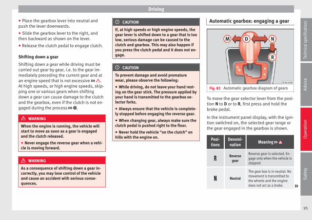
Driving
● Place the gearbox lever into neutral andpush the lever downwards.
● Slide the gearbox lever to the right, andthen backward as shown on the lever.
● Release the clutch pedal to engage clutch.
Shifting down a gear
Shifting down a gear while driving must becarried out gear by gear, i.e. to the gear im-mediately preceding the current gear and atan engine speed that is not excessive ››› .At high speeds, or high engine speeds, skip-ping one or various gears when shiftingdown a gear can cause damage to the clutchand the gearbox, even if the clutch is not en-gaged during the process ››› .
WARNING
When the engine is running, the vehicle willstart to move as soon as a gear is engagedand the clutch released.
● Never engage the reverse gear when a vehi-cle is moving forward.
WARNING
As a consequence of shifting down a gear in-correctly, you may lose control of the vehicleand cause an accident with serious conse-quences.
CAUTION
If, at high speeds or high engine speeds, thegear lever is shifted down to a gear that is toolow, serious damage can be caused to theclutch and gearbox. This may also happen ifyou press the clutch pedal and it does not en-gage.
CAUTION
To prevent damage and avoid prematurewear, please observe the following:
● While driving, do not leave your hand rest-ing on the gear stick. The pressure applied byyour hand is transmitted to the gearbox se-lector forks.
● Always ensure that the vehicle is complete-ly stopped before engaging the reverse gear.
● When changing gear, always make sure theclutch pedal is pushed right to the floor.
● Never hold the vehicle “on the clutch” onhills with the engine on.
Automatic gearbox: engaging a gear
Fig. 82 Automatic gearbox diagram of gears
To move the gear selector lever from the posi-tion N to D or to R, first press and hold thebrake pedal.
In the instrument panel display, with the igni-tion switched on, the selected gear range orthe gear engaged in the gearbox is shown.
Posi-tions
Denomi-nation
Meaning ›››
Reverse
gear
Reverse gear is selected. En-gage only when the vehicle isstopped.
Neutral
The gear box is in neutral. Nomovement is transmitted tothe wheels and the enginedoes not act as a brake. »
95
Tech
nica
l spe
cific
atio
nsA
dvic
eO
pera
tion
Saf
ety

Operation
Posi-tions
Denomi-nation
Meaning ›››
Standard
driving po-sition
The gears are changed (upand down) automatically. Thegear shifts are determined bythe engine load, your individ-ual driving style and thespeed of the vehicle.
Tiptronicdriving po-
sition(manualshift pro-gramme)
All gears can be changed (upand down) manually››› page 96. This is possibleas long as the system is notchanging gear automaticallydue to a traffic situation.
WARNING
Placing the selector lever in an incorrect posi-tion may cause loss of control of the vehicleand a serious accident.
● Do not press the accelerator when engag-ing a range of gears.
● With the engine running and a gear rangeselected, the vehicle will move off when thebrake pedal is released.
● Never engage reverse gear while driving.
● Unintentional movements of the vehiclecould cause serious injury.
● As a driver, you should never leave your ve-hicle if the engine is running and a gear rangeis engaged. If you have to leave your vehiclewhile the engine is running, you must alwaysapply the handbrake and put the selector lev-er in position N.
● Never engage the R gear range when thevehicle is moving.
● Never leave the vehicle without applyingthe handbrake. With the engine running thevehicle moves downhill regardless of the gearrange selected.
Note
If, while driving, the selector lever is acciden-tally placed in position N, lift your foot off theaccelerator. Wait until the engine is runningat idle speed before selecting a new gearrange.
Engaging gear with Tiptronic
Fig. 83 Lever in the Tiptronic position
With Tiptronic, the gears can be changed upor down manually with the automatic gear-box. When you change to the Tiptronic pro-gramme, the vehicle remains in the currently
selected gear. This is possible as long as thesystem is not changing gear automaticallydue to a traffic situation.
Using Tiptronic
● Place the lever in the position D to the lefton the Tiptronic shift gate M ››› in Auto-matic gearbox: engaging a gear on page 96.
● Press the lever forwards + or backwards– to move up or down a gear ››› Fig. 83.
● Place the lever back to the position M tothe left on the Tiptronic shift gate, to leaveTiptronic mode ››› in Automatic gearbox:engaging a gear on page 96.
With the lever in the position D, and pressingforwards + or backwards – the Tiptronicprogramme can be selected M.
CAUTION
● When accelerating, the gearbox automati-cally shifts up into the next gear shortly be-fore the maximum engine speed is reached.
● When reducing speed manually, the gearbox only shifts gear when the engine can nolonger exceed the maximum engine speed.
Driving with an automatic gearbox
The gearbox changes gear ratios automatical-ly as the vehicle moves.
96

Driving
Driving down hills
The steeper the gradient, the lower the gearyou will need to select. The lowest gears in-crease the engine braking work. Never godown hills with the selector lever in neutralN.
● You should reduce speed accordingly.
● Place the lever in the position D to the lefton the Tiptronic shift gate M ››› page 96.
● Gently pull the selector lever back – tochange down a gear.
Starting when going up a slope
The steeper the gradient, the lower the gearyou will need.
When stopping on a slope with a gear rangeengaged, the vehicle must be prevented fromrolling backwards by always pressing thebrake pedal or pulling the handbrake leverup. When starting, release the brake pedal orthe handbrake ››› .
Kick-down
The kickdown system provides maximum ac-celeration when the gear selector lever is inthe position D, or in the Tiptronic position M.
When the accelerator pedal is pressed rightdown, the automatic gearbox will shift downto a lower gear, depending on road speedand engine speed. This takes advantage of
the maximum acceleration of the vehicle››› .
When the accelerator is pressed to the floor,the automatic gearbox shifts to the next gearonly after the engine reaches the specifiedmaximum engine speed.
WARNING
Rapid acceleration can cause loss of tractionand skidding, especially on slippery ground.This could cause loss of control of the vehicleresulting in an accident and serious injury.
● Always adapt your driving style to suit theflow of traffic.
● Only use the kick-down function or rapidacceleration if visibility, weather, road andtraffic conditions so permit.
● Never put other road users in danger by ac-celerating or with your driving style.
CAUTION
If you stop on a hill with a gear range engag-ed, do not try to prevent the vehicle from roll-ing back by pressing on the accelerator. Oth-erwise, the automatic gearbox may overheatcausing damage.
Automatic gearbox malfunction
Back-up programme
When automatic gearbox warning and controllamps light up on the instrument panel, theremay be a system malfunction ››› page 93. Inthe event of some faults the automatic gear-box functions using a backup programme.When the programme is activated, it is possi-ble to drive the vehicle, however, at lowspeeds and within a selected range of gears.
With the manual gearbox, in some cases it isnot possible to drive with all the gears.
In all cases the automatic gearbox must bechecked at a specialised workshop.
Automatic gearbox overheating
The automatic gearbox can overheat with aprolonged start up, or when stopping andstarting continuously. This overheating is dis-played with a warning lamp in the instru-ment panel. Additionally, an audible warningcan be heard. Stop and let the gearbox cool››› .
The vehicle moves forward or back despitehaving selected a gear range
When the vehicle does not move in the re-quired direction, the system may not havethe gear range correctly engaged. Press thebrake pedal and engage the gear rangeagain. If the vehicle still does not move in the »
97
Tech
nica
l spe
cific
atio
nsA
dvic
eO
pera
tion
Saf
ety

Operation
required direction, there is a system malfunc-tion. Seek specialist assistance and have thesystem checked.
CAUTION
● When the gearbox is displayed as overheat-ing for the first time, the vehicle must beparked safely or must be driven at a speed ofmore than 20 km/h (12 mph).
● When the warning lamp lights up and theaudible warning is heard, the vehicle must beparked safely and the engine switched off.Let the gearbox cool down.
● To prevent damage to the gearbox, drivingmust only be continued when the warninglamps are no longer lit up. While the gearboxis overheated, starting up and driving, evenat a slow speed should be avoided.
Recommended gear display
In some vehicles, the recommended gear forreducing fuel consumption is displayed onthe instrument panel:
Display Meaning
Optimum gear.
Recommendation to change up a gear.
Recommendation to change down agear.
WARNING
The recommended gear display is intended asa guideline only; it should never replace thedriver's attention to driving carefully.
● Responsibility for selecting the correct gearfor each situation continues to lie with thedriver, for example when overtaking or climb-ing a hill.
For the sake of the environment
Selecting the most appropriate gear for thesituation will help you to save fuel.
Note
● The recommended gear display is switchedoff when the clutch pedal is pressed.
● On the display of the Portable NavigationSystem (supplied by SEAT) ››› page 123 therecommended gear can also be seen.
Run-in and economical driving
Running-in
Please observe the instructions for running-innew components.
Running-in the engine
The engine needs to be run in over the first1,500 km. During its first few hours of run-
ning, the internal friction in the engine isgreater than later on when all the movingparts have bedded down.
How the vehicle is driven for the first 1,500km influences the future engine perform-ance. Throughout the life of the vehicle, itshould be driven at a moderate speed, espe-cially when the engine is cold, as this will re-duce engine wear and increase its useful life.Never drive at extremely low engine speeds.Change down to a lower gear when the en-gine no longer runs “smoothly”. Up to 1,000kilometres the following instructions apply:
● Do not use full throttle.
● Do not force the engine above two thirds ofits maximum speed.
Between 1,000 and 1,500 kilometres, gradu-ally increase power until reaching the maxi-mum speed and high engine speeds.
Running in new tyres and brake pads
● Replacement of wheel rims and new tyres››› page 158
● Notes on the brakes ››› page 89
For the sake of the environment
If the engine is run in gently, the life of theengine will be increased and the engine oilconsumption reduced.
98

Driving
Environmental friendliness
Environmental protection is a top priority inthe design, choice of materials and manufac-ture of your new SEAT.
Constructive measures to encouragerecycling
● Joints and connections designed for easydismantling
● Modular construction to facilitate disman-tling
● Increased use of single-grade materials.
● Plastic parts and elastomers are marked inaccordance with ISO 1043, ISO 11469 andISO 1629.
Choice of materials
● Use of recycled materials.
● Use of compatible plastics in the same partif its components are not easily separated.
● Use of recycled materials and/or materialsoriginating from renewable sources.
● Reduction of volatile components, includ-ing odour, in plastic materials.
● Use of CFC-free coolants.
Ban on heavy metals, with the exceptionsdictated by law (Annex II of ELV Directive2000/53/EC): cadmium, lead, mercury, hexa-valent chromium.
Manufacturing methods
● Reduction of the quantity of thinner in theprotective wax for cavities.
● Use of plastic film as protection during ve-hicle transport.
● Use of solvent-free adhesives.
● Use of CFC-free coolants in cooling sys-tems.
● Recycling and energy recovery from resi-dues (RDF).
● Improvement in the quality of waste water.
● Use of systems for the recovery of residualheat (thermal recovery, enthalpy wheels,etc.).
● The use of water-soluble paints.
Correct economical and ecologicaldriving
Fig. 84 Fuel consumption in litres per 100 kmat 2 different outside temperatures
Fuel consumption, environmental impact andengine, brake and tyre wear depend largelyon three factors:
● Personal driving style.
● Conditions of use (weather, road surface).
● Technical requirements.
Savings of up to 25% in fuel consumptionare possible with an appropriate driving styleand the adoption of certain simple tips.
Changing gear early
General instructions: The highest gear is al-ways the most economical. As a guide, formost vehicles at a speed of 30 km/h(19 mph), drive in third gear, at 40 km/h »
99
Tech
nica
l spe
cific
atio
nsA
dvic
eO
pera
tion
Saf
ety

Operation
(25 mph) in fourth gear and at 50 km/h(31 mph) in fifth gear.
In addition, “skipping” gears when shiftingup helps to save fuel, weather and trafficconditions permitting.
Do not wait until the last moment beforechanging gear. Only use first gear when youmove off and change to second gear quickly.Avoid the kick-down function in vehicles withautomatic gearbox.
Vehicles with a gear display help to achievean economical driving style as the display in-dicates the best moment to change gear.
Let the vehicle roll
If you take your foot off the accelerator, thefuel supply is stopped and consumption isreduced.
Allow the vehicle to roll without accelerating,for example when approaching a red trafficlight. However, if the vehicle is rolling tooslowly or the distance is too long, the clutchpedal should be pressed to declutch. The en-gine will then operate at idle speed.
If the vehicle is going to be at a standstill fora period of time, switch off the engine; for ex-ample, while waiting at a level crossing.
Think ahead and “flow” with the traffic
Frequent acceleration and braking considera-bly increase fuel consumption. If you think
ahead as you drive and keep a safe distancefrom the vehicle in front, it is possible to slowdown by simply lifting your foot off the accel-erator. This eliminates the need for constantbraking and acceleration.
Calm and steady driving
Constancy is more important than speed: Themore you drive at a constant speed, the lowerthe fuel consumption.
When driving on the motorway, it is more effi-cient to drive at a constant and more moder-ate speed than to be continuously accelerat-ing and braking. As a general rule, you willreach your destination just as quickly whenyou drive at a constant speed.
The cruise control function helps you to ach-ieve a constant style of driving.
Moderate use of additional devices
It is important to travel in comfort, but con-venience systems should be used ecological-ly.
Some equipment, when connected, increasefuel consumption considerably, for example:
● Air conditioning cooling system: If the airconditioning system is required to cool tosignificantly lower temperatures than the trueoutside temperature, it will require a largeamount of energy from the engine. Therefore,we recommend that the selected temperature
for the vehicle is not too different to the out-side temperature. It is a good idea to air thevehicle before starting your journey and todrive a short distance with the windowsopen. Then you can close the windows andswitch on the air conditioning. Keep windowsclosed when travelling at high speeds. Driv-ing with the windows open increases fuelconsumption.
● Switch off the seat heating when the seatshave warmed up.
● Switch off the heated rear window when itis not moist or covered in ice.
Avoid short journeys
Fuel consumption is much higher when theengine is cold, immediately after it has beenstarted. It takes a few kilometres of drivingfor the engine to warm up and to normaliseconsumption.
The engine and catalytic converter need toreach their proper working temperature in or-der to minimise fuel consumption and emis-sions. The ambient temperature has a deci-sive influence.
Fig. 84 shows the difference in consumptionfor the same journey at +20 °C (+68 °F) andat -10 °C (+14 °F).
Therefore, unnecessary short journeysshould be avoided. Try to combine trips.
100

Driving
The vehicle uses more fuel in winter than insummer, even when other conditions are thesame.
“Warming” the engine is not only forbiddenin some countries, but in practice it is techni-cally superfluous as it is a waste of fuel.
Adjusting type pressures.
Having the correct pressure in your tyreshelps to reduce rolling resistance and, as aresult reduces fuel consumption. Increasingthe tyre pressure slightly (+0.2bar/+3 psi/+200 kPa) can help to save fuel.
When you buy new tyres, make sure they areoptimised for minimum rolling resistance.
Use low friction engine oil
The use of low viscosity totally synthetic oils,known as low friction engine oil, helps to re-duce fuel consumption. These oils reduce theresistance caused by friction in the engine,they flow around the engine more quicklyand efficiently, particularly in cold starts. Theeffect is particularly noticeable in vehiclesfrequently used for short journeys.
Always check the engine oil level and ob-serve service intervals (engine oil change in-tervals).
When purchasing engine oil, always observelegal requirements and ensure that the oil isapproved by SEAT.
Avoid carrying unnecessary loads
The lighter the vehicle, the more economicaland ecological the driving style. For example,an additional weight of 100 kg will increasefuel consumption up to 0.3 l/100 km.
Remove any unnecessary objects or loadsfrom the vehicle.
Remove optional equipment andunnecessary accessories
The more aerodynamic the vehicle, the lowerthe fuel consumption. Optional equipmentand accessories (such as roof racks or bikecarriers) reduce the aerodynamic benefits ofthe vehicle.
Therefore, we recommend you remove all op-tional and unnecessary equipment and racks,especially if you intend to drive at highspeeds.
Other factors which increase fuelconsumption (examples):
● Fault in engine management.
● Driving on hills.
WARNING
Always adapt your speed and the distance tothe vehicles ahead in line with visibility,weather conditions, the condition of the roadand the traffic situation.
Engine management andexhaust gas purificationsystem
Introduction
WARNING
The components of the exhaust system reachvery high temperatures. This could cause afire.
● Always park your vehicle so that no part ofthe exhaust system can come in contact withflammable materials (such as dried grass).
● Never apply additional underseal or anti-corrosion coatings to the exhaust pipes, cata-lytic converter or the heat shields on the ex-haust system.
Control lamps
It lightsup
Possible cause Solution
Fault in enginemanagement(Electronic PowerControl).
Take the vehicle to aspecialised work-shop as soon aspossible and havethe engine checked. »
101
Tech
nica
l spe
cific
atio
nsA
dvic
eO
pera
tion
Saf
ety

Operation
It lightsup
Possible cause Solution
Fault in catalyticconverter.
You should reducespeed accordingly.Drive carefully untilyou reach the nextspecialised work-shop. Have the en-gine checked there.
Flashes Possible cause Solution
Combustion faultwhich could dam-age the catalyticconverter.
You should reducespeed accordingly.Drive carefully untilyou reach the nextspecialised work-shop. Have the en-gine checked there.
Several warning and control lamps light upfor a few seconds when the ignition is switch-ed on, signalling that the function is beingverified. They will switch off after a few sec-onds.
CAUTION
Always pay attention to any lit control lampsand to the corresponding descriptions and in-structions to avoid damage to the vehicle.
Note
While the control lamps or maintain litup, the engine will present faults, a higher
consumption of fuel and a loss of enginepower.
Catalytic converter
The catalytic converter permits the subse-quent treatment of the exhaust gases thusreducing contaminating gas emissions. Toensure a longer working life for the exhaustsystem and catalytic converter in a petrol en-gine:
● Always use unleaded petrol.
● Never run the fuel tank completely dry.
● Do not top up with too much engine oil››› page 146.
● Do not tow-start the vehicle; use the startercables ››› page 181.
If you should notice misfiring, uneven run-ning or loss of power when the car is moving,reduce speed immediately. Have the car in-spected by a specialised workshop. If thishappens, unburnt fuel can enter the exhaustsystem and escape into the atmosphere. Thecatalytic converter can also be damaged byoverheating.
For the sake of the environment
Even when the emission control system isworking perfectly, there may be a smell ofsulphur under certain conditions. This de-
pends on the sulphur content of the fuelused.
Driving abroad
In some countries, certain safety regulationsand requirements are in force relating to ex-haust gas emissions, which differ from thetechnical characteristics of the vehicle. Be-fore travelling abroad, SEAT recommends youconsult a technical service about the legal re-quirements and the following points:
● Does the vehicle need technical modifica-tions for driving abroad, for example, adjust-ment of the headlamps?
● Does the vehicle have all the tools, diag-nostics equipment and spare parts requiredfor inspections and repairs?
● Are there any SEAT dealers in the destina-tion country?
● For petrol vehicles: Is unleaded petrol avail-able at the right octane rating?
● For diesel engines: is diesel fuel availablewith a low sulphur content?
● Are a suitable engine oil (››› page 146) andother engine fluids complying with SEATspecifications available in the destinationcountry?
102

Driver assistance systems
● Will the navigation system fitted at the fac-tory operate correctly in the destination coun-try with the available navigation data?
● Are special tyres required in the destinationcountry?
CAUTION
SEAT does not accept liability for any damageto the vehicle due to the use of a lower quali-ty fuel, an inadequate service or the non-availability of genuine spare parts.
Driving along flooded roadways
To prevent damage to the vehicle when driv-ing through water, for example, along a floo-ded road, please observe the following:
● Check the depth of the water before enter-ing the flooded zone. The water should nevercome above the lower edge of the bodywork››› .
● Do not drive faster than a pedestrian.
● Do not stop in the water, use reverse gearor switch off the engine.
● Oncoming traffic will cause waves whichraise the level of the water, making it difficultto cross the water.
● Disconnect the Start-Stop system whenevercrossing water.
WARNING
When driving through water, mud, meltedsnow, etc., please remember that due todamp or frozen brake discs and shoes in win-ter, the braking effect may be delayed, there-fore the required braking distance is greater.
● “Dry the brakes and remove ice” by brakingcarefully. Ensure that you are not endanger-ing other road-users or breaking traffic regu-lations in the process.
● After driving through water, avoid suddensharp manoeuvres.
CAUTION
● Driving through flooded areas may severelydamage vehicle components such as the en-gine, transmission, drive train or electricalsystem.
● Never drive through salt water as salt cau-ses corrosion. Always rinse any parts of thevehicle which have been in contact with saltwater.
Driver assistance systems
Braking and stability systems
Brake assist systems
The assisted braking systems ESC*, ABS,EBV, BAS, ASR, TC and EDL only operate whenthe ignition is switched on. They contributesignificantly to increasing active safety.
Electronic stability control (ESC)*
ESC* reduces the risk of skidding and increa-ses the vehicle stability by braking individualwheels under specific driving conditions.ESC* detects critical handling situations,such as understeer, oversteer and wheelspinon the driven wheels. The system stabilisesthe vehicle by braking individual wheels orby reducing the engine torque.
The ESC* has limits. It is important to realisethat ESC* is also subject to the laws of phys-ics. ESC* will not be able to deal with all sit-uations with which drivers may be faced. Forexample, if the road surface changes sudden-ly then ESC* will not be useful in all cases. Ifthe vehicle suddenly enters a section cov-ered by water, mud or snow then ESC* willnot provide assistance in the same way as ondry ground. If the vehicle loses its grip on theground and moves on a film of water (“aqua-planing”), the ESC* will not be able to help »
103
Tech
nica
l spe
cific
atio
nsA
dvic
eO
pera
tion
Saf
ety

Operation
the driver control the vehicle due to the lossof adherence with the road surface prevent-ing braking and steering. If the vehicle isdriven through series of bends at highspeed, the ESC* will not always be as effec-tive: the vehicle reaction to aggressive driv-ing is not the same as at reduced speeds.
Adjust your speed and driving style to suitvisibility, and weather, road and traffic condi-tions. ESC* cannot push the limits of the lawsof physics; improve the transmission availa-ble or maintain the vehicle on the road if alack of driver attention creates an inevitablesituation. Otherwise, ESC* assists in main-taining vehicle control in extreme situationsand uses the movements of the steeringmade by the driver to maintain the vehiclemoving in the desired direction. If the vehicleis driven at such a speed that it will leave theroad before ESC* can intervene then the sys-tem cannot provide assistance.
The ABS, BAS, ASR and EDL systems are in-corporated into the ESC*. The ESC* is alwayson1).
Anti-lock brake system (ABS)
ABS can prevent the wheels from locking dur-ing braking until just before the vehicle stopsthus helping the driver to steer the vehicleand maintain control. This means that, even
during full braking, the risk of skidding is re-duced:
● Press and hold the brake pedal fully. Do notremove your foot from the brake pedal or re-duce braking force!
● Do not “pump” the brake pedal, or reducebraking force!
● Maintain vehicle direction when brakingfully.
● When the brake pedal is released or whenthe brake force is reduced, ABS is turned off.
ABS control can be observed by vibration ofthe brake pedal and noise. You should neverexpect the ABS to reduce the braking dis-tance under any circumstances. This distancewill increase when driving on gravel, recentsnow or on icy or slippery ground.
Brake assist system (BAS)
The brake assist system may reduce the re-quired braking distance. The brake assistsystem boosts the braking force if you pressthe brake pedal quickly in an emergency. Asa result, the braking pressure increases rap-idly, the braking force is multiplied and thebraking distance is reduced. This enables theABS to be activated more quickly and effec-tively.
¡Do not lift your foot off the brake pedal!When the brake pedal is released or whenthe brake force is reduced, braking assist au-tomatically turns off the brake servo.
Traction control system (ASR) or TractionControl (TC)
In the event of wheelspin, the traction controlsystem ASR or TC reduces the engine torqueto match the amount of grip available. TheASR or TC makes some situations easier, forexample, when starting, accelerating or go-ing uphill, even in unfavourable road condi-tions.
Electronic differential lock system (EDL)
EDL is available when driving in straight linesunder normal conditions. When the EDL de-tects wheelspin, it brakes the spinning wheeland directs the power to the other one. Toprevent the disc brake of the braked wheelfrom overheating, the EDL cuts out automati-cally if subjected to excessive loads. The EDLwill switch on again automatically when thebrake has cooled down.
WARNING
Driving at high speed on icy, slippery or wetground can result in loss of vehicle control
1) Depending on the version.104

Driver assistance systems
and serious injury to the driver and passen-gers.
● Adjust your speed and driving style to visi-bility, road, traffic and weather conditions.Even though the brake assist systems, ABS,BAS, EDL, ASR and ESC* provide more securi-ty, do not take unnecessary risks while driv-ing.
● Brake assist systems can not overcome thelaws of physics. Even with ESC* and othersystems, slippery and wet roads will alwaysbe dangerous.
● Driving to quickly on wet ground can resultin the wheels losing contact with the groundin an effect known as “aquaplaning”. Withoutadherence, it is impossible to brake, steer orcontrol the vehicle.
● Brake assist systems cannot avoid acci-dents if, for example, the driver does not re-spect safety distances or drives to quickly indifficult conditions.
● Even though brake assist systems are ex-tremely effective and help control the vehiclein difficult situations, remember that the ve-hicle stability depends on tyre grip.
● When accelerating on a slippery surface,for example on ice or snow, press the acceler-ator carefully. The wheels can still slip evenwith brake assist systems resulting in loss ofvehicle control.
WARNING
The effectiveness of the ESC* can be consid-erably reduced if other components and sys-tems affecting driving dynamics are not main-tained or are not functioning correctly. Thisincludes, among others, brakes, tyres andother systems already mentioned.
● Remember that changing and fitting othercomponents to the vehicle can affect opera-tion of the ABS, BAS, ASR TC, EDL and ESC*.
● Changes to the vehicle suspension or usingunapproved wheel/tyre combinations can af-fect operation of the ABS, BAS, ASR, TC, EDLand ESC* and their effectiveness.
● Likewise, the effectiveness of ESC* de-pends on the use of suitable tyres››› page 158.
Note
● To ensure that the ESC*, ASR and TC workproperly, all four wheels must be fitted withidentical tyres. Any differences in the rollingradius of the tyres can cause the system toreduce engine power when this is not de-sired.
● If a malfunction should occur in the ABS,the ESC*, ASR, TC and EDL will also be affec-ted.
● Noises may be heard while any of theabove systems are operating.
Parking sensor system*
Introduction
The parking sensor system assists the driverwhen parking. If the rear of the vehicle is ap-proaching an obstacle, an intermittent audi-ble warning is emitted. The shorter the dis-tance, the shorter the intervals betweentones. If the vehicle is too close to the obsta-cle, the audible warning becomes constant.
If you continue to approach an obstacle whenthe sound is continuous, this means the sys-tem can no longer measure the distance.
Sensors situated on the rear bumper transmitand receive ultrasound. Using the ultrasoundsignal (transmission, reflection from the ob-stacles and reception), this system continu-ously calculates the distance between thebumper and the obstacle.
WARNING
The parking distance warning system cannotreplace the driver's assessment of the situa-tion.
● The sensors have blind spots in which ob-stacles and people are not registered.
● Always observe the area around the vehi-cle, as the sensors do not always detectsmall children, animals or objects. »
105
Tech
nica
l spe
cific
atio
nsA
dvic
eO
pera
tion
Saf
ety

Operation
● The surface of certain objects and someclothing do not reflect the ultrasound signalsfrom the parking distance system. The sys-tem cannot detect or incorrectly detectsthese objects and people wearing thesetypes of clothes.
● External sound sources can affect the park-ing distance aid signals. In this case, undercertain circumstances, people and objectswill not be detected.
CAUTION
● The sensors may not always be able to de-tect objects such as trailer draw bars, thinrails, fences, posts, trees and open boots,etc. This could result in damage to your car.
● Although the parking sensor system de-tects and warns of the presence of an obsta-cle, the obstacle could disappear from the an-gle of measurement of the sensors if it is toohigh or low and the system would no longershow it. Therefore, it will not warn you ofthese objects. Ignoring the warnings of theparking sensor system could cause consider-able damage to the vehicle.
● The bumper sensors may become damagedor misaligned, for example, when parking.
● To ensure that the system works properly,the bumper sensors must be kept clean, freeof ice and snow and uncovered.
● When cleaning the sensors with high-pres-sure or steam cleaning equipment, spray the
sensors briefly at a distance of no less than10 cm.
● Different sources of noise can produce er-rors in the parking distance warning system,e.g. parking distance warning systems fromother vehicles, inductive loops or construc-tion works machines.
● Retrofitting of components to the vehicle,such as a bicycle carrier, may interfere withthe function of the parking distance warningsystem.
Parking distance warning system
Fig. 85 Parking distance warning system sen-sors on the rear bumper
The sensors of the parking distance warningsystem are situated on the rear bumper››› Fig. 85.
Switching the parking sensor system on andoff
● Switching on: With the ignition switchedon, select reverse gear. A short audible warn-ing confirms that the parking distance warn-ing system is switched on and functioning.
● Switching off: Release reverse gear.
Things to note on the parking distancewarning system
● The parking sensor system sometimes reg-isters water on the sensors as an obstacle.
● If the distance does not change, the warn-ing signal will sound less loudly after a fewseconds. If the continuous signal sounds, thevolume will remain constant.
● When the vehicle moves away from the ob-stacle, the beeping sound automaticallyswitches off. When getting close again, it re-connects.
● Your SEAT dealership can adjust the volumeof the warning signals.
Note
A fault in the parking distance warning sys-tem is indicated through a brief audible warn-ing that is constant for about 3 seconds whenswitching it on the first time. Check the park-ing distance warning system at a Specialisedworkshop as soon as possible.
106

Driver assistance systems
Optical parking system* (OPS)
Fig. 86 On-screen OPS display: A has detec-ted an obstacle in the collision zone; B hasdetected an obstacle in the segment; C zonerecorded behind the vehicle.
The optical parking system is an extension ofthe parking distance warning system››› page 106.
On the screen of the SEAT Portable System(supplied by SEAT) the area behind the vehi-cle is shown registered by the sensors. Anyobstacles are displayed in relation to the ve-hicle ››› .
Function Necessary operations
Switching thedisplay on:
Switching on the ››› page 106 park-ing distance warning system. TheOPS switches on automatically.
Switching thedisplay off man-ually:
Press the button on the PortableNavigation System.
Function Necessary operations
Switching thedisplay off man-ually:
Release reverse gear.
Zones explored
Behind the vehicle ››› Fig. 86 C , the zone an-alysed reaches a distance of up to 150 cmand around 60 cm to the sides.
Screen display
The image displayed represents the super-vised zones in several segments. As the vehi-cle moves closer to an obstacle, the segmentmoves closer to the vehicle displayed A orB . When the penultimate segment is dis-
played, this means that the vehicle hasreached the collision zone. Stop the vehicle!
Distance fromthe vehicle tothe obstacle
Audiblewarning
Displayed in col-our on the screen:colour of the seg-ment if an obsta-cle is recognised
behind:approx. 31-150cm
beepingsound
Yellow
behind:approx. 0-30 cm
perma-nent
soundRed
WARNING
Do not be distracted from traffic to look at thescreen.
Note
● SEAT recommends practising using theparking distance warning system in a traffic-free zone or in a car park to familiarise your-self with the system and its operation.
● Representation of the registered area onthe screen of the portable navigation systemmay take up to 5 seconds.
● Note the Instruction Manual provided forthe device of the additional information relat-ing to the Portable Navigation System (sup-plied by SEAT) ››› page 123.
Cruise control* (Cruise controlsystem - CCS)
Introduction
The cruise control system (CCS) is able to in-dividually maintain the set speed when driv-ing forwards from approx. 20 km/h (15 mph).
The CCS only slows down by reducing the ac-celerator but not by braking ››› . »
107
Tech
nica
l spe
cific
atio
nsA
dvic
eO
pera
tion
Saf
ety

Operation
WARNING
Use of the cruise control could cause acci-dents and severe injuries if it is not possibleto drive at a constant speed maintaining thesafety distance.
● Do not use the cruise control in heavy traf-fic, if the distance from the vehicle in front isinsufficient, on steep roads, with severalbends or in slippery circumstances (snow,ice, rain or loose gravel), or on flooded roads.
● Never use the CCS when driving off-road oron unpaved roads.
● Always adapt your speed and the distanceto the vehicles ahead in line with visibility,weather conditions, the condition of the roadand the traffic situation.
● To avoid unexpected operation of the cruisecontrol system, turn it off every time you fin-ish using it.
● It is dangerous to use a set speed which istoo high for the prevailing road, traffic orweather conditions.
● When travelling down hills, the CCS cannotmaintain a constant speed. The vehicle tendsto accelerate under its own weight. Select alower gear or use the foot brake to slow thevehicle.
Control lamp
It lightsup
Possible cause
This cruise control system maintains theset speed of the vehicle.
Several warning and control lamps light upfor a few seconds when the ignition is switch-ed on, signalling that the function is beingverified. They will switch off after a few sec-onds.
WARNING
If the warning lamps are ignored, the vehiclemay stall in traffic, or may cause accidentsand severe injuries.
● Never ignore the warning lamps.
CAUTION
Failure to heed the warning lamps when theyappear may result in faults in the vehicle.
108

Driver assistance systems
Cruise control system operation
Fig. 87 Turn signal and main beam head-lights lever on the left of the steering column:CCS buttons and controls.
Function Control position, control operations ››› Fig. 87 Action
Switch on the CCS. Control B in the position .The system is switched on. After switching on, no speeds arestored and no regulator has yet been placed.
Activating the CCS Press button A in the area . The current speed is stored and maintained.
Temporarily switch off CCSPlace control B in the position.OR: Press the brake or clutch pedal.
The cruise control system is switched off temporarily. Thespeed setting will remain stored.
Switch on the CCS again. Press button A in the area . The stored speed is reached again and maintained.
Increasing the stored speed(during CCS setting)
Press the button A in the area briefly to increase speed in shot measures ofabout. 1 km/h (1 mph) and store. The vehicle accelerates actively until it reaches the new stored
speed.Keep button A pressed in the area for a long time to continually increasespeed until releasing and storing. »
109
Tech
nica
l spe
cific
atio
nsA
dvic
eO
pera
tion
Saf
ety

Operation
Function Control position, control operations ››› Fig. 87 Action
Reducing the stored speed (dur-ing CCS setting)
Press the button A in the area briefly to reduce the stored speed in shotmeasures of about. 1 km/h (1 mph) and store. Reduce speed without braking, by interrupting the accelerator
until reaching the new stored speed.Keep button A pressed in the area for a long time to continually decreasestored speed until releasing and storing.
Switch off the CCS. Control B in the position . The system is switched off. The stored speed is deleted.
Travelling down hills with the CCS
When travelling down hills the CCS cannotmaintain a constant speed. Slow the vehicledown using the brake pedal and reducegears if required.
Automatic off
The cruise control system (CCS) is switchedoff automatically or temporarily:
● If the system detects a fault that could af-fect the working order of the CCS.
● If you increase the stored speed by press-ing the accelerator pedal for a certain time.
● if the brake or clutch pedal is depressed.
● If the gear is changed with the manualgearbox.
● If the airbag is triggered.
Safety Assist* (City SafetyAssist function)
Introduction
The City Safety Assist function covers drivingsituations at a distance of about 10 metres infront of the vehicle, in a speed range of ap-proximately 5-30 km/h (3-19 mph).
When the system detects a possible collisionwith a vehicle in front, the vehicle preparesfor a possible emergency braking ››› .
If the driver does not react to an imminentcollision, the system can automatically brakethe vehicle in order to reduce speed facedwith a possible collision. The system canhelp to reduce the consequences of an acci-dent.
If the City Safety Assist function determinesthat the driver has braked insufficiently whenfaced with an imminent collision, the systemcan increase the brake force in order to re-
duce speed. The system can help to reducethe consequences of an accident.
WARNING
The smart technology in the City Safety As-sist system cannot change the limits imposedby the laws of physics and by the system it-self. The increased convenience offered bythe City Safety Assist system should neverprompt you to take risks. The driver alwaysassumes the responsibility of braking intime.
● The City Safety Assist function cannot pre-vent accidents or serious injury by itself.
● The City Safety Assist system may carry outunwanted brake interventions in complexdriving situations e.g. when a vehicle crossesat a short distance.
WARNING
Relying on the City Safety Assist system incity driving as part of one's driving behaviourmay cause accidents and serious injury. The
110
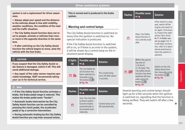
Driver assistance systems
system is not a replacement for driver aware-ness.
● Always adapt your speed and the distanceto the vehicles ahead in line with visibility,weather conditions, the condition of the roadand the traffic situation.
● The City Safety Assist function does not re-act to people, animals or vehicles that crossor move in the opposite direction in the samelane.
● If after switching on the City Safety Assistfunction the vehicle begins to move, slow thevehicle with the foot brake.
CAUTION
If you suspect that the City Safety Assist ra-dar feature is damaged, switch it off. This willavoid additional damage.
● Any repair of the radar sensor requires spe-cialist knowledge. SEAT recommends takingyour car in for technical service.
Note
● If the City Safety Assist function activates abrake, the brake pedal range is reduced. Thismakes the brake pedal seem “harder”.
● Automatic brake intervention by the CitySafety Assist function can be cancelled bypressing the clutch pedal, the acceleratorpedal or by a corrective intervention.
● During automatic braking by the City SafetyAssist function you may hear unusual noises.
This is normal and is produced in the brakesystem.
Warning and control lamps
The City Safety Assist function is switched onevery time the ignition is switched on. Nospecial indication is produced.
If the City Safety Assist function is switchedoff or on, or if there is an error in the system,it will be shown by a control lamp on the in-strument panel display.
It lightsup
Possible cause››› Solution
The City Safety As-sist function hasbeen switched onmanually usingthe button
››› Fig. 90.
The control lampturns off after about5 seconds.
FlashesPossible cause››› Solution
Fast: The City Safe-ty Assist systemfunction brakesautomatically orhas braked auto-matically.
Control lamp turnsoff automatically.
FlashesPossible cause››› Solution
Slow: City SafetyAssist function isnot currently avail-able.
If the vehicle is stop-ped, switch off theengine and switch iton again. If necessa-ry, inspect the radarsensor (dirt, frost)››› in Radar sen-sor on page 112. Ifit still does not func-tion, refer to a Speci-alised workshop tohave the system in-spected.
Within the operat-ing area of5-30 km/h(3-19 mph): TheCity Safety Assistfunction has beenswitched off man-ually using thebutton
››› Fig. 90.
Switch on the CitySafety Assist func-tion manually usingthe button
››› Fig. 90.
Several warning and control lamps shouldlight up for a few seconds when the ignitionis switched on, signalling that the function isbeing verified. They will switch off after a fewseconds. »
111
Tech
nica
l spe
cific
atio
nsA
dvic
eO
pera
tion
Saf
ety

Operation
WARNING
If the warning lamps are ignored, the vehiclemay stall in traffic, or may cause accidentsand severe injuries.
● Never ignore the warning lamps.
● Stop the vehicle safely as soon as possible.
CAUTION
Failure to heed the warning lamps when theyappear may result in faults in the vehicle.
Radar sensor
Fig. 88 In the windscreen: City Safety Assistfunction radar sensor.
Fig. 89 Radar sensor detection area.
A radar sensor on the windscreen ››› Fig. 88allows the system to detect driving situationsin front of the vehicle.
Vehicles ahead can be detected up to a dis-tance of about 10 m.
WARNING
The laser beam on the radar sensor can pro-duce serious injuries to the eyes.
● Never focus optical devices, e.g. a camera,a microscope or a magnifying glass closerthan 100 mm from the radar sensor.
● Note that the laser beam can stay activewhen the City Safety Assist system is switch-ed off or unavailable. The laser beam is notvisible to the human eye.
CAUTION
If the windscreen is dirty or frosted in thearea of the radar sensor, e.g. due to rain, mist
or snow, the City Safety Assist system mayfail to operate as a result.
● Always keep the radar sensor area free ofdirt and frost.
● Use a small brush to remove snow and ade-icer spray to remove ice.
CAUTION
A damaged windscreen in the radar sensorarea may cause the City Safety Assist func-tion to fail to operate.
● Replace the windscreen if it is scratched,cracked or chipped by stones in the radarsensor area. Only use a windscreen author-ised by SEAT. Carrying out repairs is not per-mitted (e.g. in the case of damage suffered inan impact from a stone).
● When replacing the windscreen wipers, on-ly use windscreen wipers authorised by SEAT.
● Do not paint the radar sensor area on thewindscreen, or cover it with adhesives or oth-er materials.
112

Driver assistance systems
Function
Fig. 90 In the lower part of the centre con-sole: Button for the City Safety Assist func-tion.
Switching on and off the City Safety Assistfunction
● Press the ››› Fig. 90 button on the centreconsole.
When the City Safety Assist function isswitched on, the control lamp lights upon the dash panel within the operationalrange, i.e. for speeds between 5-30 km/h(3-19 mph).
Switch off the City Safety Assist function inthe following situations
Switching off the City Safety Assist function isrecommended in the following situations››› :
● While the vehicle is being towed.
● If the vehicle has been taken to an auto-matic car wash.
● If the vehicle is above a test bed.
● If the radar sensor is faulty.
● After the radar sensor has been involved ina collision.
● When driving off road (overhanging branch-es).
● If objects are protruding above the bonnet,e.g. a load carried on the roof that signifi-cantly protrudes over the front.
● If the windscreen is damaged in the radarsensor area.
WARNING
Failure to switch off the City Safety Assistfunction in the above situations may result inaccidents and serious injury.
● Switch off the City Safety Assist function incritical situations.
Special driving situations
Fig. 91 A: Vehicle on a bend. B: Motorcyclistdriving ahead out of range of the radar sen-sor.
Fig. 92 Other vehicles changing lanes »
113
Tech
nica
l spe
cific
atio
nsA
dvic
eO
pera
tion
Saf
ety

Operation
The City Safety Assist function is limited bythe laws of physics and by the nature of thesystem itself. For this reason, this may pro-duce reactions from the City Safety Assistsystem in certain circumstances that are lateor unexpected by the driver. For this reason,always pay due attention and if necessary, in-tervene.
For example, the following driving situationsrequire special attention:
Driving through a bend
When entering or leaving a “long” bend, thevehicle may decelerate when the radar sen-sor detects a vehicle travelling in the adjoin-ing lane ››› Fig. 91 A. To interrupt decelerationyou can accelerate, turn the steering wheel orpress the clutch.
Narrow vehicles in front
The radar sensor will only detect narrow vehi-cles in front if they are in the sensor detec-tion zone ››› Fig. 91 B. This applies especiallyto narrow vehicles such as motorbikes.
Other vehicles changing lanes
Vehicles moving into your lane in close prox-imity can cause unexpected braking from theCity Safety Assist system ››› Fig. 92. To inter-rupt deceleration you can accelerate, turn thesteering wheel or press the clutch.
Malfunction in the radar sensor
If the radar sensor operation is impaired, forexample due to heavy rain, mist, snow or dirt,the City Safety Assist system function is tem-porarily switched off. On the instrument pan-el display the control lamp flashes.
When the fault in the radar sensor has beenrectified, the City Safety Assist system func-tion automatically becomes available. Thecontrol lamp switches off.
The following conditions could prevent theCity Safety Assist system from functioning:
● Tight bends.
● Accelerator pressed all the way down to thefloor.
● If the City Safety Assist system is switchedoff or there is a fault ››› page 111.
● If the radar sensor is dirty, covered or over-heated ››› page 112.
● In the event of snow, heavy rain or densefog.
● If there are vehicles in front.
● Vehicles changing lanes.
● Vehicles moving in the opposite directionin the same lane.
● Very dirty vehicles with a low degree of re-flection.
● Presence of thick dust.
Hill driving assistant*
Operation
This function is only included in vehicles withESC.
The hill driving assistant helps the driver tomove off and upward on a hill when the vehi-cle is stationary.
The system maintains brake pressure for ap-proximately two seconds after the drivertakes his foot off the brake pedal to preventthe vehicle from lurching backward when it isstarted. During these 2 seconds, the driverhas enough time to release the clutch pedaland accelerate without the vehicle movingand without having to use the handbrake,making start-up easier, more comfortableand safer.
These are the basic operation conditions:
● being on a ramp or hill/slope,
● doors closed,
● vehicle completely stationary,
● engine running and foot on the brake,
● besides having a gear engaged or being inneutral for manual gear change and with theselector lever at positions S, D or R in vehi-cles with an automatic gearbox.
This system is also active when reversing up-hill.
114

Driver assistance systems
WARNING
● If you do not start the vehicle immediatelyafter taking your foot off the brake pedal, thevehicle may start to roll back under certainconditions. Depress the brake pedal or usethe hand brake immediately.
● If the engine stalls, depress the brake ped-al or use the hand brake immediately.
● When following a line of traffic uphill, if youwant to prevent the vehicle from rolling backaccidentally when starting off, hold the brakepedal down for a few seconds before startingoff.
Note
The Official Service or a specialist workshopcan tell you if your vehicle is equipped withthis system.
Start-Stop system
Warning lamps
Itlights
upPossible cause Solution
The Start-Stop systemis enabled.
Itlights
upPossible cause Solution
The Start-Stop systemis enabled but the en-gine cannot be auto-matically stopped.
Contact a special-ised workshop.
The Start-Stop systemcannot start the en-gine.
Start the engine byhand using the ve-hicle's key››› page 86.
There is a fault in thealternator.
››› page 154
Flash-es
Possible cause Solution
The Start-Stop systemis not available.
Contact a special-ised workshop.
Some warning and control lamps will light upbriefly when the ignition is switched on tocheck certain functions. They will switch offafter a few seconds.
WARNING
Observe the safety warnings ››› in Controland warning lamps on page 40.
Start-Stop system
Fig. 93 At the top of the centre console: Start-Stop system button
With the Start-Stop system enabled, the en-gine is automatically stopped when the vehi-cle is at a standstill. It will start again auto-matically as required.
This function remains enabled while the igni-tion is switched on. The instrument panel dis-play shows information on the current status››› page 115.
Disconnect the Start-Stop system by handwhenever crossing water.
Vehicles with a manual gearbox
● When the vehicle is stopped, put it intoneutral and release the clutch pedal. The en-gine will stop.
● To restart, simply engage the clutch. »
115
Tech
nica
l spe
cific
atio
nsA
dvic
eO
pera
tion
Saf
ety

Operation
Vehicles with an automatic gearbox
● When the vehicle is at a standstill, depressthe brake or keep it pressed down. The en-gine switches off.
● The engine will start again as soon as yourelease the brake pedal.
● With the selector lever set to position N,the engine will not start until a range of gearsis selected or the accelerator pedal is de-pressed.
Important conditions for the engine to stopautomatically
● The driver's seat belt must be fastened.
● The driver door must be closed.
● The bonnet must be closed.
● The engine must have reached a minimumtemperature.
● The vehicle must have moved since the lasttime the engine was stopped.
● The vehicle's battery must be sufficientlycharged.
● The battery temperature must not be toolow or too high.
● The vehicle must not be on a very steepslope.
Conditions for the engine to restartautomatically
The engine can be automatically restarted inthe following cases:
● If the vehicle starts to moves.
● If the battery voltage drops.
Conditions requiring engine start-up usingthe key
The engine has to be manually started in thefollowing cases:
● If the driver unbuckles his/her seat belt.
● If the driver door is opened.
● If the bonnet is opened.
Switching the Start-Stop system on and off
● Press the button situated in the centreconsole ››› Fig. 93.
● The button will light up when the Start-Stopsystem is switched off.
The engine will start immediately if the vehi-cle is in Stop mode when the system isswitched off by hand.
WARNING
The smart technology included in the hillhold cannot change the laws of physics. Donot let the extra convenience afforded by the
hill hold tempt you into taking any riskswhen driving.
● Any accidental movement of the vehiclecould result in serious injury.
● The hill hold is not a replacement for driverawareness.
● Adjust your speed and driving style to visi-bility, weather, road and traffic conditions.
● The hill hold cannot always keep the vehi-cle at a standstill on a slope or brake suffi-ciently when travelling downhill (e.g. on slip-pery or frozen surfaces).
WARNING
The brake servo and the electromechanicalsteering do not work when the engine isswitched off.
● The vehicle must never be allowed to movewith the engine switched off.
● Disconnect the Start-Stop system beforeworking in the engine compartment.
CAUTION
The vehicle's battery could be damaged if thevehicle is used for long periods at very highoutside temperatures.
Note
In some cases, it may be necessary to startthe engine by hand using the key. Refer to
116

Towing bracket device
the corresponding control lamp on the instru-ment panel.
Towing bracket device
Trailer coupling
Information about trailer coupling
The vehicle is not certified for trailer cou-pling. The vehicle is not factory-equippedwith a towing bracket, nor is it possible to ret-rofit it.
WARNING
Installing a towing bracket on the vehiclemay cause accidents and serious injurieswhile operating the vehicle.
● Never install a towing bracket on the vehi-cle.
● The trailer may be released from the vehiclewhen the vehicle is moving.
CAUTION
Any type of towing bracket installed on thevehicle can cause serious and costly damagethat are not covered under the SEAT guaran-tee.
117
Tech
nica
l spe
cific
atio
nsA
dvic
eO
pera
tion
Saf
ety

Advice
Advice
Care and maintenance
Accessories, replacement ofparts and modifications
Introduction
WARNING
The use of spare parts and accessories, or in-correctly performed modifications or repairsmay result in damage to the vehicle, acci-dents and serious injury.
● SEAT strongly recommends you to only useSEAT approved accessories and SEAT® origi-nal spare parts. These parts and accessorieshave been specially tested by SEAT for suita-bility, reliability and safety.
● Have any repairs or modifications carriedout at a specialised workshop. These work-shops have the necessary tools, diagnosticsequipment, repair information and qualifiedpersonnel.
● Only mount parts with the same specifica-tions as the parts fitted at factory.
● Never mount, fasten or fit objects such asdrink holders or telephone cradles over thecovers of the airbag modules or within theirdeployment zones.
● Only use wheels and tyre combinationswhich have been approved by SEAT for yourvehicle type.
Accessories and spare parts
SEAT recommends you consult an OfficialService before purchasing accessories andspare parts or consumables. For example,when fitting accessories at a later date, orwhen replacing a component. A SEAT OfficialService will advise you as to the legal require-ments and manufacturer's recommendationsregarding accessories, spare parts and othercomponents.
SEAT recommend you use only approvedSEAT accessories and genuine SEAT spareparts®. These parts and accessories havebeen specially tested by SEAT for suitability,reliability and safety. In addition, SEAT tech-nical services will guarantee that assembly isperformed professionally.
Although we continually monitor the market,SEAT cannot guarantee that products not ap-proved by SEAT are reliable, safe or suitablefor the vehicle. Therefore, SEAT cannot acceptliability, even in those cases authorised byan officially recognised technical inspectionoffice or other official body.
Any retro-fitted equipment which has a directeffect on vehicle control must be approved by
SEAT for use in your vehicle and bear the emark (the European Union's authorisationsymbol). This includes cruise control systemsor electronically controlled suspension.
If any additional electrical devices are fittedwhich do not serve to control the vehicle it-self, these must bear the mark (EuropeanUnion manufacturer conformity declaration).This includes refrigerator boxes, laptops orventilator fans.
WARNING
Unprofessional repairs or modifications tothe vehicle may affect the performance of theairbags, and may cause operating faults or fa-tal accidents.
● Never mount, fasten or fit objects such asdrink holders or telephone cradles over ornext to the covers of the airbag modules orwithin their deployment zones.
● Objects placed over the airbag covers, orwithin their deployment zones, could lead toserious injury or loss of life if the airbags aretriggered.
Fluids and consumables
All vehicle fluids and consumables, such asnotched belts, tyres, coolant fluids, engineoils, spark plugs and batteries are continual-ly being developed. Therefore all fluids and
118

Care and maintenance
consumables should be changed at a speci-alised workshop. Technical services are per-manently informed of any modifications.
WARNING
The incorrect use or handling of fluids or con-sumables may result in accident, serious in-jury, burns or intoxication.
● Therefore, fluids must always be storedclosed in their original container.
● Never store fluids in empty food containersor bottles as other people may accidentallydrink the fluid.
● Keep all fluids and consumables out ofreach of children.
● Read and observe the information andwarnings given on the fluid containers.
● Only work in the open air or in well-ventila-ted zones, when using products which giveoff harmful vapours.
● Never use fuel, turpentine, engine oil, ace-tone or any other volatile liquid in the main-tenance of the vehicle. These are toxic andhighly flammable. They could lead to fire orexplosions!
CAUTION
● Only use appropriate fluids. Do not confusefluids as this can cause serious malfunctionsor engine damage.
● Accessories and other components moun-ted in front of the air inlet reduce the cooling
effect of the coolant. If the engine is runningunder great strain in high outside tempera-tures, it could overheat.
For the sake of the environment
Leaking fluids could pollute the environment.Collect any spilt fluids in suitable containersand dispose of them in accordance with legis-lation and with respect for the environment.
Repairs and technical changes
When performing repairs and technical mod-ifications, SEAT's directives must be ob-served! ›››
Unauthorised modifications to the electroniccomponents or software in the vehicle maycause malfunctions. Due to the way the elec-tronic components are linked together in net-works, other indirect systems may be affec-ted by the faults. This may significantly affectthe vehicle's performance, increase compo-nent wear and could mean that the vehicleregistration documents are no longer valid.
Your SEAT Official Service cannot be held lia-ble for any damage caused by technical mod-ifications or repairs performed incorrectly.
The SEAT Official Service does not accept lia-bility for damage resulting from technicalmodifications or repairs performed incorrect-
ly; neither is the SEAT warranty valid in thesecases.
SEAT recommends you have any technicalmodifications or repairs performed at a SEATOfficial Service and that you use genuineSEAT spare parts®.
Vehicles with special accessories andequipment
The manufacturers of additional equipmentguarantee that the equipment complies withapplicable laws and regulations with respectto the environment, in particular Directives2000/53/CE and 2003/11/CE. The first direc-tive governs the disposal of end-of-life vehi-cles while the second refers to the restric-tions on the marketing and use of certaindangerous substances and preparations.
The vehicle owner should keep the documen-tation for the additional equipment safelyand hand it over to the scrap yard at the endof the vehicle's service life. This ensures thatany additional equipment mounted in end-of-life vehicles is correctly disposed of with re-spect for the environment.
WARNING
Repairs or modifications which are not per-formed correctly may result in damage or er-rors in the vehicle operation, affecting the ef-fectiveness of the driver assist systems. Thiscould result in serious accident. »
119
Tech
nica
l spe
cific
atio
nsA
dvic
eO
pera
tion
Saf
ety

Advice
● All repairs and modifications to the vehicleshould only be performed by a specialisedworkshop.
Repair and faults in the airbag system
When performing repairs and technical mod-ifications, SEAT's directives must be ob-served! ›››
Modifications and repairs to the front bump-er, doors, front seats, and repairs to the roofor chassis should only be carried out in aspecialised workshop. These componentsmay contain parts or sensors belonging tothe airbag system.
If work is carried out on the airbag system orparts have to be removed and fitted on thesystem when performing other repair work,parts of the airbag system may be damaged.The consequence may be that, in the event ofan accident, the airbag inflates incorrectly ordoes not inflate at all.
So that the effectiveness of the airbag is notreduced and that removed parts do not causeany injuries or environmental pollution, regu-lations must be observed. These require-ments are known to specialised workshops.
Modifications to the vehicle suspension mayaffect the operation of the airbag system inthe event of collision. For example, if wheeland tyre combinations not approved by SEAT
are used, or if the vehicle height is lowered,the suspension is stiffened or the suspensionsprings, telescopic arms, dampers, etc., aremodified, the results received by the airbagsensors and sent to the control unit may notbe accurate. For example, some modifica-tions to the suspension could increase theforce measured by the sensors and result inthe triggering of the airbag systems in colli-sions. Under normal conditions, the meas-ured values would be lower and the airbagwould not have been triggered. Other modifi-cations may reduce the forces measured bythe sensors and prevent the airbags from be-ing triggered when they should.
WARNING
Repairs or modifications which are not per-formed correctly may result in damage or er-rors in the vehicle operation, affecting the ef-fectiveness of the airbag systems. This couldresult in serious or fatal accidents.
● All repairs and modifications to the vehicleshould only be performed by a specialisedworkshop.
● Airbag modules must never be repaired: ifdamaged, they must be replaced.
● Never fit recycled or reused airbag compo-nents in your vehicle.
WARNING
Modifications to the vehicle suspension, in-cluding the use of unauthorised wheel and
tyre combinations, may affect the perform-ance of the airbags and increase the risk ofserious or fatal injury in the event of acci-dent.
● Never fit suspension components which arenot identical to the original parts in the vehi-cle.
● Never use wheel and tyre combinations notapproved by SEAT.
Retro-fitting of two-way radios
An exterior aerial is required for the use oftwo-way radios in the vehicle.
The retro-fitting of electrical or electronic ap-pliances in the vehicle is subject to their ap-proval for use in your vehicle. Under certaincircumstances, this could mean that your ve-hicle registration documents are no longervalid.
SEAT has approved your vehicle for use withtwo-way radios providing the following condi-tions are observed:
● The exterior aerial must be mounted pro-fessionally.
● The maximum transmitting power is 10watts.
The optimal reach of the equipment is onlyachieved with an external aerial.
120

Care and maintenance
Check first with a specialised workshop thatunderstands the technical possibilities of in-stallation if you wish to use a two-way radiowith a transmitting power of over 10 watts.SEAT recommends taking your car in for tech-nical service.
All legal requirements, together with the in-structions for the use of two-way radios mustbe observed.
WARNING
If the two-way radio is not securely fastenedin position, it could be sent flying around thevehicle in the event of sharp braking, suddenmanoeuvres or accident, causing injury.
● While driving, two-way radios must be se-curely fastened in position, outside the air-bags deployment zones, or safely stowedaway.
WARNING
When using a two-way radio without a con-nection to an exterior aerial, the maximumpermitted levels of electromagnetic radiationmay be exceeded. This is also the case if theaerial has not been correctly installed.
● You should only use a two-way radio insidethe vehicle if it has first been correctly con-nected to an exterior aerial.
Information stored by the controlunits
Your vehicle is fitted at the factory with a ser-ies of electronic control units responsible forthe engine and gearbox management. In ad-dition, the control units supervise the per-formance of the exhaust gas system and theairbag systems.
Therefore, while the vehicle is being driven,these electronic control units are continuous-ly analysing the vehicle data. In the event offaults or deviations from the theoretical val-ues, only this data is stored. Normally, thewarning lamps on the instrument panel lightup in the event of faults.
This data can only be read and analysed us-ing special equipment.
The storing of the data allows specialisedworkshops to detect and repair faults. Storeddata may include:
● Data relating to the engine or the gearbox
● Speed
● Direction of travel
● Braking force
● Detection of seat belt
The vehicle control units never record conver-sations held by passengers in the vehicle.
In vehicles equipped with an emergency callfunction via the mobile phone or other appli-
ances connected in the vehicle, it is possibleto send the vehicle position. If the controlunit records an accident with airbag activa-tion, the system may automatically send asignal. This will depend on the network oper-ator. Normally, transmission is only possiblein areas with good coverage.
Event Data Recorder
The vehicle is not fitted with an event data re-corder.
An event data recorder temporarily stores thevehicle information. Therefore, in the event ofan accident, it is possible to obtain detailedinformation about how the accident occur-red. Vehicles with airbag systems can storedata relating to impact speed, seat belt sta-tus, seat positions and airbag activationtimes may be stored, etc. The volume of datadepends on the manufacturer.
Event data recorders can only be mountedwith authorisation from the vehicle ownerand, in some countries, they are governed bylocal legislation.
Reprogramming control units
On the whole, all the data required for thecomponent management is stored in the con-trol units. The programming of certain con-venience functions, such as the turn signals,individual door opening and instructions onthe display can be modified using special »
121
Tech
nica
l spe
cific
atio
nsA
dvic
eO
pera
tion
Saf
ety

Advice
equipment at the workshop. If the comfortfunctions are reprogrammed, the informationand Instruction Manual descriptions will notcoincide with the modified functions. There-fore, SEAT recommends that any modifica-tions be recorded in the section “Other work-shop notes” in the Maintenance Programme.
The SEAT Official Service must have a recordof any modification to the programming.
Reading the vehicle fault memory
There is a diagnostics connector in the vehi-cle interior for reading the vehicle fault mem-ory. The fault memory documents errors anddeviations from the theoretical values of theelectronic control units.
The diagnostics connector is in the driverside footwell area, next to the lever for open-ing the bonnet, below a cover.
The fault memory should only be read and re-set by a specialised workshop.
Using a mobile telephone in a vehiclewithout connection to an exterioraerial
Mobile telephones transmit and receive radiowaves also called high-frequency energy,both when in use and when on stand-by. Sci-entific studies state that radio waves exceed-ing certain values may be harmful to the hu-
man body. International committees and au-thorities have established limits and direc-tives in order to ensure electromagnetic radi-ation from mobile phones remains within cer-tain limits that do not endanger health. Nev-ertheless, there is no conclusive scientificevidence that wireless telephones are totallysafe.
That is why some experts recommend moder-ate use of the mobile telephone, and the ap-pliance of measures to reduce radiation onthe human body.
When a mobile phone not connected to anexterior aerial is used inside the vehicle, theelectromagnetic radiation may be greaterthan if the mobile phone were connected to abuilt-in aerial or to another exterior aerial.
If the vehicle is fitted with a suitable hands-free device that allows the employment ofnumerous additional mobile telephone func-tions with compatible Bluetooth technolo-gy®, it will comply with the legislation inmany countries which only permits the use ofmobile phones inside vehicles using ahands-free device.
The hands-free system of the Portable Navi-gation System (supplied by SEAT) has beendesigned for use with conventional mobilephones and phones with Bluetooth technolo-gy® ››› page 123. Mobile telephones must beplaced in a suitable telephone support orstored safely in the vehicle. If a support is
used for the telephone, it must be securelyfastened to the base plate. The mobile will besecure on the instrument panel and alwayswithin reach of the driver only by followingthese procedures. Mobile telephone connec-tion with an external aerial is carried out sub-ject to the hands-free device, via the tele-phone support or by the Bluetooth® connec-tions present in the mobile telephone andthe vehicle.
If the mobile phone is connected to an aerialincorporated into the vehicle or an exterioraerial connected to the vehicle, it will help re-duce the electromagnetic radiation transmit-ted and the risk to human health. It will alsoimprove the quality of the connection.
If the phone is used inside the vehicle with-out the hands-free system, it will not be se-curely fastened and will not be connected tothe exterior aerial of the vehicle telephone.Nor will the telephone charge if it is not onthe support. In addition, some calls maybreak off and the quality of the connectionwill be affected.
Mobile telephones should only be used in-side the vehicle if they are connected to ahands-free system. SEAT recommends usingan external aerial should you wish to use amobile telephone inside the vehicle.
Bluetooth® is a registered trademark of Blue-tooth® SIG, Inc.
122

Care and maintenance
WARNING
If the mobile phone is not securely fastenedin position, it could be sent flying around thevehicle in the event of sharp braking, suddenmanoeuvres or accident, causing injury.
● While driving, the mobile telephone, otherequipment including telephone accessoriessuch as telephone supports, notepads andnavigators must be correctly secured, awayfrom the airbags deployment zones, or storedin a safe place.
WARNING
When using a mobile telephone or two-wayradio without connecting an external aerial,the maximum permitted levels of electromag-netic radiation in the vehicle may be excee-ded, thus putting the driver and the rest ofthe vehicle occupants in danger. This is alsothe case if the aerial has not been correctlyinstalled.
● A minimum of 20 centimetres should bekept between mobile phone aerials and artifi-cial pacemakers, as mobile telephones mayaffect the working of pacemakers.
● Do not keep mobile phones in breast pock-ets directly above pacemakers.
● Immediately switch off the mobile tele-phone if you suspect any interference withpacemakers or other types of medical equip-ment.
SEAT Portable System*
Fig. 94 In the centre console: Remove thenavigator.
Fig. 95 Remove the navigator holder
The SEAT Portable System (supplied by SEAT)allows for the use of other vehicle functionssuch as additional applications ››› .
The gradient and the angle of vision can beset by moving the navigator to the requiredposition ››› Fig. 94 ››› .
The Portable Navigation System InstructionManual can be observed directly on theequipment.
Functions1)
● Multifunction display (MFI) shown with ad-ditional instruments ››› page 36.
● Operation of a factory-fitted radio and a››› Booklet Radio system connected multime-dia player.
● Image display.
● Navigation.
● Hands-free system for mobile telephonesvia Bluetooth.
● Door open.
● Optical parking system (OPS).
● Recommended gear and driving advice.
Observe the Instruction Manual in theequipment
● Connect the Portable Navigation System.
● Press the button more on the screen.
● Press the Manual button. »
1) subject to the vehicle123
Tech
nica
l spe
cific
atio
nsA
dvic
eO
pera
tion
Saf
ety

Advice
● Select the required chapter and press thecorresponding button.
Removing and fitting the navigator
● Securely support the navigator.
● Press the release button 1 until the deviceis released from its holder.
● Take the navigator out and store it safely.
To fit the navigator, place it in the upper sup-port and push the lower part inside the hold-er until it engages with a click ››› .
Removing and fitting the navigator holder
● Press the holder release button ››› Fig. 95(arrow).
● Remove the holder from the dash panel inan upwards direction.
● If necessary, close the opening with thecorresponding cover.
In order to fit the holder, place it on the open-ing from above and press in a downwards di-rection until it engages with a click. ››› .
WARNING
Any distraction may lead to an accident, withthe risk of injury. Operating the navigatorcould distract you from the traffic.
● Always stay alert and drive responsibly.
● Select volume settings that allow you toeasily hear signals from outside the vehicleat all times (e.g. emergency service sirens).
● Setting the volume too high may causedamage to your hearing. This also applies ifthe device is set to high volumes for a shortperiod.
WARNING
Journey instructions and traffic signalsshown on the navigation system may differ tothe current traffic situation.
● Traffic signals and driving regulations takeprecedence over journey instructions and in-dications from the navigation system.
● Adjust your speed and driving style to visi-bility, road, traffic and weather conditions.
WARNING
If the navigator is not securely fastened inposition, it could be sent flying around thevehicle in the event of sharp braking, suddenmanoeuvres or accident, causing injury.
● Fit the navigator housing safely on the cor-responding opening on the dash panel.
● Always place the navigator securely in itsholder or store it in the vehicle.
CAUTION
An unsuitable gradient and angle of visionsetting can damage the navigator.
● When adjusting the navigation device,move it with care and not beyond its limits.
CAUTION
Excessively high or low outside temperaturescan affect the Portable Navigation System op-eration or damage the device.
● Always take the Portable Navigation Sys-tem with you when you leave the vehicle toprotect it from excessively high or low tem-peratures and intense sunlight.
CAUTION
Humidity can damage the Portable Naviga-tion System connections on the dash panel.
● Do not clean the holder for the navigationdevice with moist products. Use a dry cloth.
Note
SEAT recommends taking the Portable Navi-gation System with you when you leave thevehicle to prevent it from being stolen.
124

Care and maintenance
Jacking points for raising vehicle
Fig. 96 Front jacking points for raising vehiclewith lifting platform or jack
Fig. 97 Rear jacking points for raising vehiclewith lifting platform or jack
Always use the jacking points indicated inthe figures ››› Fig. 96 and ››› Fig. 97 whenraising the vehicle. If the vehicle is not liftedat these points, it could be seriously dam-aged ››› or lead to serious injury ››› .
The vehicle should not be lifted using liftingplatforms with lift pads containing fluid.
When raising a vehicle using a platform orjack, a series of precautionary measures arerequired. Do not raise the vehicle with a lift-ing platform or jack unless you have receivedtraining in how to do so and know how to doso safely.
Notes on raising the vehicle with a jack››› page 174.
WARNING
The improper use of the lifting platform orthe jack when raising the vehicle may resultin accidents or serious injury.
● Before raising the vehicle, please observethe manufacturer's instructions for the plat-form or jack, and the legal requirements,where applicable.
● There should not be anyone inside the ve-hicle when it is being raised or once it is inthe air.
● Only use the jacking points indicated in thefigures ››› Fig. 96 and ››› Fig. 97 when raisingthe vehicle. If the vehicle is not lifted at theindicated points, it may fall from the platformwhile the engine or gearbox is being dis-mounted, for example.
● The jacking points should be centrallyaligned and firmly positioned on the platformsupport plates.
● Never start the engine when the vehicle israised! The vehicle may fall from the platformdue to the engine vibrations.
● If it is necessary to work underneath the ve-hicle while it is raised, you should check thatthe supporting stands have an adequate loadcapacity.
● Never climb onto the lifting platform.
● Always make sure that the weight of the ve-hicle does not exceed the lifting platformload capacity.
CAUTION
● Never raise the vehicle at the engine oilsump, the gearbox or the rear or front axles.
● Always use an intermediate rubber supportto prevent damage to the vehicle underbody.Check that the arms of the lifting platform areable to move with obstruction.
● The arms should not come into contact withthe side running boards or other parts of thevehicle.
Care and cleaning the vehicleexterior
Introduction
Regular maintenance and washing help tomaintain the value of the vehicle. This may »
125
Tech
nica
l spe
cific
atio
nsA
dvic
eO
pera
tion
Saf
ety

Advice
also be one of the requirements for acknowl-edging warranty claims in the event of body-work corrosion or paint defects.
Products suitable for the care of your vehicleare available at any technical service.
WARNING
Car-care products may be toxic and hazard-ous. If car care products are not suitable orare used inappropriately, this could result inaccident, serious injury, burns or intoxica-tion.
● Car care products must always be stored inthe original container which should be keptclosed.
● Observe information provided by the manu-facturer.
● To prevent confusion, never store car careproducts in empty food cans, bottles or othercontainers.
● Keep all care products out of reach of chil-dren.
● Harmful vapours may be produced when us-ing car care products. Therefore, care prod-ucts should only be used in well-ventilatedspaces or in the open air.
● Never use fuel, turpentine, engine oil, ace-tone or any other volatile liquid to wash,clean or care for the vehicle. These are toxicand highly flammable.
WARNING
Inappropriate care and cleaning of vehiclecomponents may effect the vehicle safetyequipment, increasing the risk of severe in-jury.
● Vehicle components should only becleaned and maintained in accordance withthe manufacturer's instructions.
● Only use approved or recommended careproducts.
CAUTION
Cleaning products which contain solvents willdamage the material.
For the sake of the environment
Only wash the vehicle in areas allocated forthis purpose, to prevent dirty water whichmay be contaminated by oil, grease or fuel,from entering the drains. In some places,even washing it outside the planned areas isbanned.
For the sake of the environment
Where possible, always use products whichrespect the environment.
For the sake of the environment
The remains of car care products should notbe disposed of with ordinary household
waste. Observe information provided by themanufacturer.
Washing the vehicle
The longer substances such as insects, birddroppings, resinous tree sap, road dirt, in-dustrial deposits, tar, soot or road salt andother aggressive materials remain on the ve-hicle, the more damage they do to the paint-work. High temperatures (for instance due tostrong sunlight) further intensify the corro-sive effect. The vehicle undercarriage shouldalso be thoroughly washed at regular inter-vals.
Automatic car washes
Always observe the instructions provided atthe automatic car wash. The standard pre-cautionary measures prior to entering the carwash should be taken to avoid damage tothe vehicle (close all windows, fold in exteriormirrors). If the vehicle is fitted with additionalcomponents (spoiler, roof-rack, aerial, etc.),check with the car wash supervisor whetherthese can enter the car wash ››› .
The vehicle paintwork is so durable that thevehicle can normally be washed withoutproblems in an automatic car wash tunnel.However, wear and damage to the paintworkwill depend on the type of car wash used.
126

Care and maintenance
SEAT recommends the use of car washeswithout brushes.
To remove traces of wax on windows and toprevent wiper blades from scratching, pleaseobserve the following ››› page 128, Cleaningwindows and exterior mirrors.
Washing the car by hand
When washing the car by hand, use plenty ofwater to soften the dirt first, and rinse off aswell as possible.
Then clean the vehicle with a soft sponge,glove or brush using only slight pressure.Start at the roof and work downwards. Spe-cial car shampoo should only be used forvery persistent dirt.
Rinse the sponge or glove thoroughly and of-ten.
Wheels, sills and similar should be cleanedlast. Use a second sponge for this.
WARNING
Sharp components on the vehicle may causeinjury.
● Protect arms and hands from sharp edgeswhen cleaning the vehicle undercarriage orthe interior of the wheel hubs.
WARNING
After the vehicle has been washed, the brak-ing effect will be reduced (and the brakingdistance increased) due to moisture (and icein winter) on the brakes.
● “Dry the brakes and remove ice” by brakingcarefully. Ensure that you are not endanger-ing other road-users or breaking traffic regu-lations in the process.
CAUTION
● The temperature of the water must not ex-ceed +60 °C (+140 °F).
● To avoid damage to the paintwork, do notwash the vehicle in full sun.
● Do not use rough sponges or similar whichcould damage the surface to clean away thetraces of insects.
● Never wipe the headlights with a dry clothor sponge, always moisten first. It is best touse soapy water.
● Washing the vehicle in low temperatures:When washing the vehicle with a hose, donot direct water into the lock cylinders or thegaps around the doors or roof. Locks andseals could freeze!
CAUTION
To prevent damage to the vehicle, please ob-serve the following before entering an auto-matic car wash:
● Compare the distance between the vehiclewheels and the distance between the guide-rails of the car wash to prevent damage to thewheels and tyres!
● Switch off the rain sensor before taking thevehicle to an automatic car wash.
● Compare the height and width of your vehi-cle with the available height and width whenentering and driving through the car wash.
● Fold in exterior mirrors Electrically retracta-ble exterior mirrors must not be folded in orout by hand. Always use the electrical powercontrol.
● To avoid damaging the bonnet paintwork,rest the windscreen wipers on the windscreenafter drying the wiper blades. Do not let themfall!
● Lock the rear lid to prevent it from openingunexpectedly while inside the car wash.
Washing the vehicle with highpressure cleaning apparatus
When cleaning the vehicle with a high-pres-sure cleaner, always follow the operating in-structions for the equipment. Pay special at-tention to the required pressure of the jetand the distance between the jet and the ve-hicle ››› .
Keep a suitable distance from soft materials,such as rubber hoses or insulating material, »
127
Tech
nica
l spe
cific
atio
nsA
dvic
eO
pera
tion
Saf
ety

Advice
and from the parking distance warning sys-tem sensors. The sensors of the parking dis-tance warning system are situated on the rearbumper ››› .
Do not use a nozzle that sprays the water outin a direct stream or one that has a rotatingjet for forcing off dirt ››› .
WARNING
The incorrect use of high pressure cleaningequipment could result in permanent dam-age, visible or invisible, to the tyres or othermaterials. This could result in a serious acci-dent.
● Ensure there is a suitable distance betweenthe nozzle and the tyres.
● Never wash tyres with a concentrated jet orso-called “dirt blasters”. Even at large spray-ing distances and short cleaning times, youmay damage the tyres.
WARNING
After the vehicle has been washed, the brak-ing effect will be reduced (and the brakingdistance increased) due to moisture (and icein winter) on the brakes.
● “Dry the brakes and remove ice” by brakingcarefully. Ensure that you are not endanger-ing other road-users or breaking traffic regu-lations in the process.
CAUTION
● The temperature of the water must not beabove +60 °C (+140 °F).
● To avoid damage to the paintwork, do notwash the vehicle in full sun.
● To ensure that the system functions well,the sensors located on the bumper must bekept clean and free from ice. When cleaningwith pressure hoses and steam cleaners, thesensors should be sprayed only briefly. A dis-tance of 10 cm between the sensors and thesteam / hose nozzle must be observed.
● Do not use a high pressure cleaner to re-move ice or snow from windows
● Washing the vehicle in low temperatures:When washing the vehicle with a hose, donot direct water into the lock cylinders or thegaps around the doors or roof. Locks andseals could freeze!
Cleaning windows and exteriormirrors
Cleaning windows and exterior mirrors
Spray windows and exterior windows with astandard window cleaner containing alcohol.
Dry the windows with a clean chamois leath-er or a lint-free cloth. The chamois leathersused on painted surfaces are not suitable forcleaning windows because they are soiled
with wax deposits which could smear thewindows.
Use window cleaner or a silicone remover toclean rubber, oil, grease and silicone depos-its off ››› .
Removing wax deposits
Automatic car washes and certain car careproducts may leave wax deposits on the win-dows. These deposits can only be removedwith a special product or cleaning cloths. Ifwax deposits are left on the windscreen andthe rear window, the blades can scratch theglass. SEAT recommends you wipe the waxdeposits off the windscreen and the rear win-dow with a soft cloth each time after youhave washed the vehicle.
A window cleaning detergent which helps todissolve the wax may be added to the wind-screen washer fluid to prevent the wiperblades from scratching the windscreen.Please ensure you add the cleaning productin the correct proportions. Products for re-moving grease do not eliminate the wax de-posits ››› .
Special cleaning products or window clothsare available at any technical service. To re-move wax deposits, SEAT recommends thefollowing products:
128

Care and maintenance
● For the hottest time of the year: the windowcleaner for summer use G 052 184 A1. Pro-portion 1:100 (1 part detergent, 100 partswater) in the windscreen washer reservoir.
● All year round: the window clean-er G 052 164 A2; proportion 1:2 in wind-screen washer bottle (1 part concentrate, 2parts water) in winter, up to -18 ℃ (-0.4 °F),or 1:4, during the rest of the year.
● Window cloths G 052 522 A1 for all win-dows and exterior mirrors.
Removing snow
Use a small brush to remove snow from thewindows and exterior mirrors.
Removing ice
If possible, use a de-icing spray to removeice. If you use an ice scraper, push it in onedirection only without swinging it. If you pullthe scraper backwards, the dirt may scratchthe window.
WARNING
Dirty or misted windows reduce visibility inall directions and increase the risk of acci-dent and serious injury.
● Do not drive unless you have good visibilitythrough all windows!
● Remove ice and snow from the windowsand demist inside and out.
CAUTION
● Never mix our cleaning products with otherproducts not recommended by SEAT in thewindscreen washer reservoir. This could leadto flocculation and may block the windscreenwasher jets.
● Do not use hot or warm water to remove iceor snow from the windows and exterior mir-rors. The glass could crack!
● The heating element for the rear window islocated on the inner side of the window. Donot stick adhesive labels over the heating el-ements and never clean the inside of the rearwindow with corrosive or acid products orother similar chemical cleaning products.
Caring for and polishing the vehiclepaintwork
Waxing
Regular waxing protects the paintwork. It istime to apply a good coat of wax when waterno longer forms droplets and rolls off theclean paintwork.
Even if a wax solution is used regularly in theautomatic car wash, SEAT recommends pro-tecting the paint with a hard wax coating atleast twice a year.
Polishing
Polishing is only necessary if the paint haslost its shine, and the gloss cannot bebrought back by applying wax.
If the polish does not contain wax, a waxproduct should be applied after polishing.
CAUTION
● To prevent damage, car polish or hard waxshould not be used on components painted inmatt paint, plastic components and the glassheadlamp and tail light covers.
● Do not polish your vehicle in a sandy ordusty environment.
Care and cleaning of chrome andaluminium wheel rims
● Use a clean, damp, lint-free, smooth clothto clean anodized surfaces.
● If there is a lot of dirt, use a special clean-ing product which does not contain solvents.
● Then, polish the chrome and aluminiumwheel trims with a smooth dry cloth.
CAUTION
In order to prevent damage to the aluminiumand chrome wheel trims:
● Do not clean or polish them in direct sun-light. »
129
Tech
nica
l spe
cific
atio
nsA
dvic
eO
pera
tion
Saf
ety

Advice
● Do not clean or polish them in sandy ordusty environments.
● Do not use abrasive cleaning agents suchas home cream cleaners.
● Do not use insect sponges, scouring pads,or similar products to clean insect deposits.
● Do not polish dirty surfaces.
● Do not use products containing solvents.
● Do not use hard wax.
CAUTION
Chrome hub caps or wheel covers may havebeen painted additionally. Do not treat themwith aluminium or chrome wax products, norchrome or aluminium polish. Instead, usecommercial paint wax or polish.
Cleaning wheels
Cleaning steel wheels
Use an industrial cleaner to remove brakedust. Therefore, clean wheels regularly with aseparate sponge.
Any damage to the paint on steel wheelsshould be touched up before the metal startsto rust.
Caring for and cleaning alloy wheels
Remove road salt and brake dust by washingthe wheels approximately once a fortnight.
Use an acid free detergent to clean the wheelrims. SEAT recommends treating the wheelrims thoroughly with a hard wax about onceevery three months.
It is important to remove road salt and brakedust by washing the wheels at regular inter-vals, otherwise the finish will be impaired.
Always use an acid-free detergent for alloywheel rims. Car polish or other abrasiveagents should not be used for maintainingthe rims.
If the protective coating on the paint hasbeen damaged (for example, hit by a stone),it should be repaired immediately.
Caring for rubber seals
The rubber seals on doors, windows, etc., re-main flexible, provide a better seal and lastlonger if they are regularly treated with aproduct specifically designed for use on rub-ber.
Before applying the product, use a soft clothto remove dust and dirt from the rubberseals.
De-icing the door lock cylinder
To de-ice the lock cylinders, SEAT recommendthe use of genuine SEAT spray with lubricat-ing and anti-corrosive properties.
CAUTION
The use of products containing degreasingagents to de-ice the locks may rust the lockcylinder.
Protection of vehicle undercarriage
The vehicle underbody is coated to protect itfrom chemical and mechanical damage. Theprotective coat on the undercarriage maywear from use while driving. Therefore, SEATrecommends that the protective coating onthe undercarriage and on the running gearshould be regularly checked, and repaired ifnecessary.
WARNING
Additional underseal or anti-corrosion prod-ucts could catch fire due to the high tempera-tures reached by the exhaust gas system andother engine components.
● Do not apply additional underseal or anti-corrosion products to the exhaust pipes, cat-alytic converters, heat shields or other partsof the vehicle which reach high temperatures.
130

Care and maintenance
Cleaning the engine compartment
The engine compartment of any motor vehi-cle is a potentially hazardous area››› page 143.
The engine compartment should only becleaned by qualified personnel. If it is notcorrectly cleaned, the anti-corrosion coatingand consequently electrical components maybe damaged. Moreover, water may filter di-rectly into the vehicle interior through the wa-ter chamber ››› .
If the engine compartment is very dirty, al-ways take the vehicle to a specialised work-shop for professional cleaning. SEAT recom-mends taking your car in for technical serv-ice.
Water box
The water box is in the engine compartment,between the windscreen and the engine, andbeneath a perforated cover. Air is taken inthrough the water box from outside to the ve-hicle interior via the heating and air condi-tioner.
Leaves and other loose objects should beregularly cleaned away from the water box ei-ther by hand or with a vacuum.
WARNING
When working on the engine or in the enginecompartment, there is a risk of injury, burns,accident or fire.
● Before starting work, please ensure you arefamiliar with the required procedure and thesafety precautions ››› page 143.
● SEAT recommends getting a specialisedworkshop to do these jobs.
CAUTION
If water is manually poured into the water box(e.g. using a high pressure cleaning appli-ance), this could cause significant damage tothe vehicle.
For the sake of the environment
Only wash the engine compartment in areasallocated for this purpose, to prevent dirtywater which may be contaminated by oil,grease or fuel, from entering the drains. Insome places, even washing this compartmentoutside planned areas for this purpose isbanned.
Caring for and cleaning thevehicle interior
Introduction
The dye from many items of modern clothing(e.g. dark jeans) is not always colour-fast.Seat upholstery (material and leather), espe-cially when light-coloured, may visibly discol-our if the dye comes out of clothing (evenwhen used correctly). This is not an uphols-tery defect but indicates that the dye in theitem of clothing is not sufficiently colour-fast.
WARNING
Car-care products may be toxic and hazard-ous. If car care products are not suitable orare used inappropriately, this could result inaccident, serious injury, burns or intoxica-tion.
● Car care products must always be stored inthe original container which should be keptclosed.
● Observe information provided by the manu-facturer.
● To prevent confusion, never store car careproducts in empty food cans, bottles or othercontainers.
● Keep all care products out of reach of chil-dren. »
131
Tech
nica
l spe
cific
atio
nsA
dvic
eO
pera
tion
Saf
ety

Advice
● Harmful vapours may be produced when us-ing car care products. Therefore, care prod-ucts should only be used in well-ventilatedspaces or in the open air.
● Never use fuel, turpentine, engine oil, ace-tone or any other volatile liquid to wash,clean or care for the vehicle. These are toxicand highly flammable.
WARNING
Inappropriate care and cleaning of vehiclecomponents may effect the vehicle safetyequipment, increasing the risk of severe in-jury.
● Vehicle components should only becleaned and maintained in accordance withthe manufacturer's instructions.
● Only use approved or recommended careproducts.
CAUTION
● Cleaning products which contain solventswill damage the material.
● To avoid damage, stubborn stains shouldbe removed by a specialised workshop.
Note
Suitable vehicle care products are availablefrom your technical service.
Treating your upholstery
To treat and maintain your seat upholstery,keep the following in mind ››› :
● Before entering the vehicle, close any Vel-cro fasteners that might snag on the uphols-tery or trim fabric. Any open Velcro fastenersmay damage the trim or upholstery fabrics.
● To prevent damage, avoid direct contactbetween sharp decorative objects and theupholstery and trim fabrics. Decorative ob-jects include zips, rivets and rhinestones onclothing and belts.
● From time to time, clean the dust that gath-ers in the perforations, folds and seams sothat the surfaces of the seats are not dam-aged by its abrasive effect.
● Make sure clothes are colour-fast to avoidthem running and staining the upholstery.This is especially important if the upholsteryis light in colour.
CAUTION
If the instructions for upholstery and trimcare are not followed, they may deteriorateand discolour.
Note
SEAT recommends you take the vehicle to aSpecialised workshop to treat any stains onthe upholstery caused by the discolourationof clothing.
Padding and fabric trim cleaning
Normal cleaning
● Before applying cleaning products, pleaseread the instructions for handling and thewarnings shown on the container.
● The upholstery, textile covers, and carpetshould be regularly vacuumed (with vacuumbrush).
● We recommend that you use a soft spongeor lint-free, micro-fibre cloth for normal clean-ing ››› .
General superficial dirt on upholstery andtextile covers can be cleaned with a normalfoam cleaning product.
If the upholstery and the material trims arevery dirty, we recommend you have themcleaned by a specialist cleaning form.
Cleaning stains
It may be necessary to clean the whole sur-face and not only the stain itself. Especially ifthe surface has been dirtied through normaluse. Otherwise, the stained area may be-come lighter than the rest of the surface aftertreatment.
132

Care and maintenance
Type ofstain
Cleaning the vehicle
Water-basedstains, e.g.coffee or fruitjuice.
– Use a sponge and wipe with a solu-tion of water and wool wash.– Dry with a dry, absorbent cloth.
Persistentstains, e.g.chocolate ormake-up.
– Apply a washing pastea) directly tothe stain and allow it to work.– Apply clean water using a sponge ordamp cloth to remove the cleaningproduct deposits.– Dry with a dry absorbent cloth.
Grease-basedstains, e.g. oilor lipstick.
– Apply neutral soap or cleaningpastea) and allow it to work.– Remove dissolved grease or colourparticles with an absorbent cloth.– Then apply clean water. Take care notto soak the upholstery.
a) Bile soap can be used as a cleaning paste.
CAUTION
● Brushes should only be used to clean themats and floor mat! Other surfaces may bedamaged if a brush is used.
● Do not use steam cleaning equipment, asthe dirt becomes more encrusted in the mate-rial when steam is applied.
● Never use brushes for cleaning damp mate-rial as they could damage the surface.
Cleaning storage compartments,drinks holders and ashtray
Fig. 98 In the front part of the centre console:Storage compartment with cup holder.
Fig. 99 Ashtray removed and open with areato stub cigarettes
Cleaning storage compartments and drinksholders
● Use a clean, damp, lint-free cloth to cleanparts.
● If this does not provide satisfactory results,we recommend using a special solvent-freeplastic cleaning product.
Cleaning the ashtray
● Extract the ashtray and empty it.
● Clean the ashtray with a dishcloth.
Use a toothpick or similar to remove ash fromthe area where cigarettes are stubbed out››› Fig. 99.
Care and cleaning of plastic parts,wooden trim and the instrumentpanel
● Use a clean, damp, lint-free cloth to cleanparts.
● Clean plastic parts (inside and outside thevehicle) and the dash panel with a specialsolvent-free product for the care and clean-ing of plastic, approved by SEAT ››› .
● Wash wooden trims with a mild soap andwater solution.
● Clean the Portable Navigation System hous-ing (Supplied by SEAT) with a dry cloth only. »
133
Tech
nica
l spe
cific
atio
nsA
dvic
eO
pera
tion
Saf
ety

Advice
WARNING
Solvents cause the surfaces of the airbagmodules to become porous. If an airbag is ac-cidentally triggered, the detachment of plas-tic parts could cause serious injury.
● Never clean the dash panel and the surfa-ces of the airbag modules with cleaners con-taining solvents.
CAUTION
When cleaning the instrument panel, be care-ful not to dampen the Portable NavigationSystem connections as this can damage theelectrical installation.
Cleaning seat belts
If the seat belt is very dirty, the belt retractormay not work correctly thus preventing theseat belt from operating correctly.
The seat belts should never be removed fromthe vehicle for cleaning.
● Use a soft brush to remove the worst dirt››› .
● Pull the seat belt right out and leave it out.
● Clean dirty seat belts with a gentle soapand water solution.
● Wait until they are completely dry.
● Only allow the seat belt to retract when it iscompletely dry.
WARNING
Check the condition of all the seat belts atregular intervals. If the webbing or otherparts of the seat belt are damaged, the vehi-cle should be taken to a Specialised work-shop immediately and the belts should be re-placed. It is extremely dangerous to drive us-ing damaged seat belts and could result inserious injury or loss of life.
● Seat belts and their components must nev-er be cleaned with chemical products, norshould they be allowed to come into contactwith corrosive liquids, solvents or sharp ob-jects. This could affect the strength of theseat belt webbing.
● Seat belts should be completely dry beforeretracting. Dampness could damage the beltretractor so that it does not operate correctly.
● Do not allow liquids or foreign bodies to en-ter the buckle fastenings. This could damagethe buckles and seat belts.
● Never attempt to repair, modify or remove aseat belt yourself.
● Always have damaged seatbelts replacedimmediately by seat belts approved for thevehicle in question by SEAT. Seat belts whichhave been worn in an accident and stretchedmust be replaced by a specialised workshop.Renewal may be necessary even if there is noapparent damage. The belt anchorage shouldalso be checked.
Notes for the user
Introduction
WARNING
Failure to treat the vehicle with the correctcare increases the risk of accident and injury.
● Observe legal requirements.
● Observe the Instruction Manual.
CAUTION
If the vehicle is not properly cared for, dam-age may occur.
● Observe legal requirements.
● Carry out regular maintenance of the vehi-cle, according to specifications in the Mainte-nance Programme.
● Observe the Instruction Manual.
134

Care and maintenance
Labels and plates
Fig. 100 Warnings relating to handling theCity Safety Assist system radar sensor func-tion
Some parts in the engine compartment comefrom the factory with certificates of safety, la-bels or plates containing important informa-tion regarding the operation of the vehicle,for example, on the petrol cap, on the pas-senger's sun visor, on the driver door strut, oron the floor of the boot.
● Never remove these certificates of safety,labels or plates, and ensure they are kept ingood condition and are legible.
● If a vehicle part, bearing a certificate ofsafety, label or plate, is replaced, the special-ised workshop should attach the informationback in the same place.
Certificate of safety
A certificate of safety on the door strut statesthat all the safety standards and regulationsestablished by the national traffic authoritiesresponsible for road safety were met at thetime of manufacture. It may also give themonth and year of manufacture, togetherwith the chassis number.
Warning of high voltage label
There is a label close to the bonnet lockwhich warns of high voltage in the vehicle'selectrical system.
Warning relating to the City Safety Assistsystem laser sensor
There are some warning and informationsigns on the City Safety Assist system lasersensor ››› Fig. 100.
Using your vehicle in other countriesand continents
The vehicle is manufactured at the factory foruse in a particular country in accordance withthe national legislation in force at the time ofmanufacture.
If the vehicle is sold in another country orused in another country for an extended peri-od of time, the applicable legislation of thatcountry should be observed.
It may be necessary to fit or remove certainpieces of equipment or to deactivate certainfunctions. Service work may also be affected.This is particularly true if the vehicle is usedin a different climate for an extended periodof time.
As there are different types of frequencybands around the world, you may find thatthe radio system or the Portable NavigationSystem (supplied by SEAT) supplied at thefactory does not work in another country.
CAUTION
● SEAT does not accept liability for any dam-age to the vehicle due to the use of a lowerquality fuel, an inadequate service or thenon-availability of genuine spare parts.
● SEAT does not accept liability if the vehicledoes not comply in part or in full with the le-gal requirements of other countries or conti-nents.
Radio reception and the aerial
For factory-fitted radio equipment, the aerialfor radio reception is fitted to the roof of thevehicle.
Note
If electrical equipment such as mobile tele-phones, is used near a roof aerial, you may »
135
Tech
nica
l spe
cific
atio
nsA
dvic
eO
pera
tion
Saf
ety

Advice
observe interference in the reception of AMstations.
Notes on SEAT repairs
Following payment, information about au-thorised SEAT services and authorised SEATrepairs in the following locations can be re-quested:
Clients in Europe, Asia, Australia, Africa,Central America and South America
Contact a technical service or specialisedworkshop, or request the corresponding doc-umentation at www.erwin.volkswagen.de.
WARNING
Repairs or modifications which are not per-formed correctly may result in damage or er-rors in the vehicle operation, affecting the ef-fectiveness of the driver assist and airbagsystems. This could result in serious acci-dent.
● Have any repairs or modifications carriedout at a specialised workshop.
Conformity certification
The respective manufacturer hereby declaresthat the products indicated below complywith basic requirements and the following
provisions and important legislation on thedate of manufacture of the vehicle, amongothers FCC Part 15.19, FCC Part 15.21 andRSS-Gen Issue 1:
Radio frequency equipment
● Electronic gearbox lock.
● Vehicle key
Electrical equipment
● 12 volt power socket
Collection and scrapping of end-of-lifevehicles
Collection of end-of-life vehicles
SEAT is already prepared for the momentwhen you wish to scrap your vehicle and of-fers you an environmentally-friendly solution.An extensive network of used car receptioncentres already exists in much of Europe. Af-ter the vehicle has been delivered, you willreceive a certificate of destruction describingthe environmentally friendly scrapping of thevehicle in accordance with applicable legisla-tion.
We will collect the used vehicle free ofcharge, provided it complies with all nationallegislation.
Please see your technical service for furtherinformation about the collection and scrap-ping of end-of-life vehicles.
Scrapping
The relevant safety requirements must be ob-served when the vehicle or components ofthe airbag or belt tensioner systems arescrapped. These requirements are known tospecialised workshops.
136

Checking and refilling levels
Checking and refilling levels
Fuel
Introduction
You will find a factory-fitted sticker containinginformation on the type of fuel for your vehi-cle on the inside of the fuel tank flap.
WARNING
Refuelling or handling fuel carelessly cancause an explosion or fire resulting in seriousburns and injuries.
● Fuel is a highly explosive, easily flammablesubstance.
● Observe current safety instructions and lo-cal regulations concerning the handling offuel.
Types of fuel
The type of fuel to use when refilling will de-pend on the vehicle's engine. You will find afactory-fitted sticker containing informationon the type of fuel for your vehicle on the in-side of the fuel tank flap.
SEAT recommends the use of sulphur-free orlow sulphur fuel to reduce consumption andprevent engine damage.
Possibletypes of
fuelAlternative names
Further in-formation
91a) RON Normal petrol, normalunleaded petrol
››› page 13795a) RON Premium unleaded
petrol (95 RON)
98a) RON Premium unleadedpetrol (98 RON)
a) RON = Regulation Octane Number
Petrol
Petrol types
Vehicles with petrol engines must refuel us-ing unleaded petrol according to Europeannorm EN 228 ››› .
Petrol types are categorised according totheir octane number (e.g. 91, 95, 98 or 99RON (RON = “Research Octane Number”).You may use petrol with a high octane num-ber than the one recommended for your en-gine. However, this has no advantage interms of fuel consumption and engine power.
SEAT recommends refuelling with a low sul-phur content or sulphur-free petrol to reducefuel consumption for petrol engines.
Petrol additives
The quality of the fuel influences the behav-iour, power and service life of the engine.This is why the petrol you use should carrysuitable additives already included by thepetrol industry, free of metals. These addi-tives will help to prevent corrosion, keep thefuel system clean and prevent deposits frombuilding up in the engine.
If good-quality petrol with metal-free addi-tives is not available or engine problemsarise, the necessary additives must be addedwhen refuelling ››› .
Not all petrol additives have been shown tobe effective. The use of unsuitable petrol ad-ditives may cause significant damage to theengine and the catalytic converter. Metal ad-ditives should never be used. Metal additivesmay also be contained in petrol additives forimproving anti-detonation ratings or octaneratings ››› .
SEAT recommends “genuine VolkswagenGroup Fuel Additives for petrol engines”.These additives can be bought at SEAT deal-ers, where information on how to use themcan also be obtained.
CAUTION
● Do not refuel if the filler indicates that thefuel contains metal. LRP (lead replacementpetrol) fuels contain high concentrations of »
137
Tech
nica
l spe
cific
atio
nsA
dvic
eO
pera
tion
Saf
ety
Advice
metal additives. Using them may damage theengine!
● Only use fuel with an octane rating that isin line with the norm EN 228, otherwise sig-nificant damage could be caused to the en-gine and fuel system. Furthermore, it couldlead to a loss of performance with the conse-quent engine fault.
● The use of unsuitable petrol additives couldseriously damage the engine and the catalyt-ic converter.
● If, in exceptional circumstances, petrol witha lower octane rating to that recommended isused, only use moderate engine speeds and alight throttle. Avoid using full throttle andoverloading the engine. Otherwise enginedamage may occur. Fill up with fuel of a suita-ble octane rating as soon as possible.
● Just filling one full tank of leaded fuel orwith other metal additives would seriouslyimpair the efficiency of the catalytic convert-er and could damage it.
Natural gas
Natural gas, in addition to others, can be inliquid form.
Liquefied natural gas (LNG) is the result ofheavy cooling of natural gas. Therefore itsvolume is considerably reduced comparedwith compressed natural gas (CNG). In vehi-cles with a natural gas engine, liquefied nat-ural gas cannot be directly refilled, as the gas
would expand excessively in the vehicle gastank.
Therefore, vehicles with a natural gas enginemust only be refuelled using compressednatural gas ››› .
Natural gas quality and consumption
Natural gas is divided into the groups H andL depending on its quality.
Gas type H has a superior heating power andinferior nitrogen and carbon dioxide contentthan type L. The higher the heating power ofthe natural gas, the lower the consumptionwill be.
However, the heating power and the propor-tion of nitrogen and carbon dioxide can fluc-tuate within the quality groups. Therefore, ve-hicle consumption can also vary when usingone type of gas only.
The engine management automaticallyadapts to the natural gas used according toits quality. Therefore, different quality gasescan be mixed in the tank, without the needfor comprehensive draining before applying adifferent quality gas.
Natural gas and safety
If you can smell gas or suspect that there is aleak ››› :
● Stop the vehicle immediately.
● Switch the ignition off.
● Open the doors to appropriately ventilatethe vehicle.
● Immediately extinguish cigarettes.
● Move away from the vehicle or switch offobjects that may cause sparks or a fire.
● If you continue to smell gas, do not contin-ue driving!
● Seek specialist assistance. Have the faultrepaired.
WARNING
Failure to act when you can smell gas in thevehicle or when refuelling can cause seriousinjuries.
● Carry out the necessary operations.
● Leave the danger zone.
● If necessary, warn the emergency services.
WARNING
The vehicle is not prepared to use liquefiednatural gas (LNG) and this fuel must not beadded under any circumstances. Liquefiednatural gas can cause the natural gas tank toexplode, resulting in serious injury.
Note
The natural gas system must be subject toregular inspections at a specialised work-shop in accordance with the MaintenanceProgramme.
138

Checking and refilling levels
Filling the tank
Introduction
The fuel tank flap is on the rear right of thevehicle.
WARNING
Refuelling or handling fuel carelessly cancause an explosion or fire resulting in seriousburns and injuries.
● Always make sure that you correctly closethe fuel cap to avoid evaporation and fuelspillage.
● Fuels are highly explosive and inflammablesubstances that can cause serious burns andinjuries.
● Fuel could leak out or be spilt if the engineis not switched off or if the filler fuel nozzle isnot fully inserted into the tank filler neckwhen refuelling. This could lead to a fire, ex-plosion and severe injuries.
● When refuelling, turn off the engine andturn off the ignition for safety reasons.
● Always turn off mobile telephones, radioapparatus and other radio wave emittingequipment before refuelling. Electromagneticwaves could cause sparks and lead to a fire.
● Never enter the vehicle while refuelling. If itis absolutely necessary to enter, close thedoor and touch a metal surface before touch-
ing the filler nozzle again. This will preventthe generation of static electricity. Sparkscould cause a fire when refuelling.
● Never handle fuel close to flames, sparks orobjects with slow combustion (e.g. ciga-rettes).
● Avoid static electricity and electro-magnet-ic radiation when refuelling.
● Observe the safety regulations of the serv-ice station.
● Never spill fuel on the vehicle or in the lug-gage compartment.
WARNING
For safety reasons, SEAT does not recommendcarrying a spare fuel canister in the vehicle.Fuel could be spilled and catch fire, above allin case of an accident and this applies to afull container as well as empty containers.This could lead to explosions, fires and inju-ries.
● Observe the following if you exceptionallyhave to carry fuel in a canister:
– Never place a fuel container, to fill it, in-side the vehicle or on the vehicle, for ex-ample, in the luggage compartment. Fill-ing in these circumstances could createan electrostatic charge and spark thatcould ignite fuel fumes.
– Always place the canister on the groundto fill it.
– Insert the fuel nozzle into the neck of thecanister as far as possible.
– If you are using a metal fuel canister, thenozzle must always touch the canisterwhile it is being filled to avoid static elec-tricity.
– Follow the legal requirements for the use,storage and transport of spare fuel canis-ters.
– Insure that the fuel container complieswith manufacturing standards, for exam-ple, ANSI or ASTM F852-86.
CAUTION
● Always remove any fuel spilled anywhereon the vehicle to avoid damage to the wheelhousing, the tyre and vehicle paintwork.
● Refuelling a petrol engine with diesel cancause serious engine and fuel system dam-age; the resulting malfunctions are not cov-ered by the SEAT warranty. If you refuel withthe wrong type of fuel, never start the engine.This applies to even the smallest amount ofthe wrong fuel. Seek specialist assistance.With the engine running, the composition ofthe wrong fuel could significantly damage thefuel system and the engine itself.
For the sake of the environment
Fuels can contaminate the environment. Col-lect any spilt service fluids and allow a pro-fessional to dispose of them.
139
Tech
nica
l spe
cific
atio
nsA
dvic
eO
pera
tion
Saf
ety

Advice
Control lamps and fuel gauge
Fig. 101 On the instrument panel: fuel gaugefor petrol
Fig. 102 On the instrument panel: Fuel gaugefor petrol and natural gas.
The fuel gauge can vary depending on the ve-hicle equipment ››› Fig. 101 or ››› Fig. 102.
It lights upGauge position
››› Fig. 101Possible cause ››› Solution
a) Red mark (arrow)The fuel tank is almost empty.The reserve tank is being used ››› page 203.
Refuel as soon as possible ››› .
– The vehicle is running in natural gas operating mode. –
a) This only applies to vehicles with the fuel gauge on the dash panel ››› Fig. 101.
140

Checking and refilling levels
Flashes for about 10seconds
State of the bars Possible cause ››› Solution
and the segments
remaininga)Reserve zone (four small segments)
The fuel tank is almost empty.The reserve tank is being used ››› page 203.
Refuel as soon as possible ››› .
– The vehicle is running in natural gas operating mode. –
a) This only applies to vehicles with the fuel gauge on the dash panel display.
Several warning and control lamps light upfor a few seconds when the ignition is switch-ed on, signalling that the function is beingverified. They will switch off after a few sec-onds.
In natural gas engines
The warning lamp lights up when both fueltypes (petrol and natural gas) have reachedreserve level.
The warning lamp lights up when the vehi-cle is running in natural gas operating mode.
The warning lamp switches off when thenatural gas is exhausted. The enginechanges to operate with petrol.
Problem: if the vehicle is left parked for along time just after refuelling, the gas levelindicator does not accurately indicate thesame level shown after refuelling when thevehicle is started up again. This is not due toa leak in the system, but to a drop in pres-sure in the gas tank for technical reasons af-
ter a cooling phase immediately after refuel-ling.
WARNING
Driving with insufficient fuel reserve could re-sult in the vehicle breaking down in trafficand a serious accident.
● If the fuel level is too low then the fuel sup-ply to the engine can become irregular espe-cially on slopes.
● If the engine “is choked” or stalls due tolack of or irregularity of the fuel supply, thepower steering as well as all of the driver as-sistance systems including braking assis-tance will stop working.
● Always refuel when there is only one quar-ter of the fuel tank left to avoid running out offuel.
CAUTION
● Always pay attention to any lit controllamps and to the corresponding descriptions
and instructions to avoid damage to the vehi-cle.
● Never run the fuel tank completely dry. Anirregular fuel supply may lead to ignitionfaults and unburnt fuel could enter the ex-haust system. This could damage the catalyt-ic converter.
Note
The arrow next to the fuel pump symbol onthe instrument panel ››› Fig. 101 indicates theside of the vehicle on which the tank flap islocated.
141
Tech
nica
l spe
cific
atio
nsA
dvic
eO
pera
tion
Saf
ety

Advice
Refuelling with petrol
Fig. 103 Open tank flap with tank cap attach-ed to the holder
Before refuelling, always turn off the engine,the ignition, mobile telephones, auxiliaryheating and keep them off during refuelling.
Opening the fuel tank cap
● The tank flap is at the rear of the vehicle onthe right.
● Pull the rear zone of the fuel tank flap toopen.
● Unfold the key shaft if necessary››› page 43.
● Insert the vehicle key into the lock cylinderof the fuel tank plug and turn the key in ananticlockwise direction.
● Take out the fuel tank plug by turning it inan anticlockwise direction and rest it on theupper part of the fuel tank flap ››› Fig. 103.
Refuelling
The correct petrol type for the vehicle is loca-ted on a sticker inside the fuel tank flap››› page 137.
● If the automatic filler nozzle is operatedcorrectly, it will switch itself off as soon asthe fuel tank is full ››› .
● Do not continue to refuel if it is turned off!Otherwise, this will fill the expansion cham-ber and fuel may leak out if the ambient con-ditions are warm.
Closing the fuel tank cap
● Screw on the fuel tank filler plug in a clock-wise direction until it is fully inserted with aclick.
● Insert the vehicle key into the lock cylinderof the fuel tank plug, turn the key in a clock-wise direction and remove the key.
● Press the tank flap until you hear it click in-to place. The tank flap must be flush with thebody contour.
WARNING
Do not continue refilling once the fuel nozzlehas switched itself off. The fuel tank may befilled too much. As a result, fuel may spurtout and spill. This could lead to a fire, explo-sion and severe injuries.
CAUTION
● Always remove any fuel spilled anywhereon the vehicle to avoid damage to the wheelhousing, the tyre and vehicle paintwork.
For the sake of the environment
Fuels can contaminate the environment. Col-lect any spilt service fluids and allow a pro-fessional to dispose of them.
Refuelling with natural gas
Fig. 104 Tank flap open: gas filler mouth 1 ,filler mouth retainer 2
Before refuelling, the engine and the igni-tion, mobile telephone and heating must beswitched off separately ››› .
It is also essential to carefully read the in-structions for the natural gas pump.
142

Checking and refilling levels
The vehicle is only prepared for refuellingwith Compressed Natural Gas (CNG) ››› . Re-fuelling with another type of natural gas isnot allowed, e.g. Liquefied Nature Gas (LNG)or hydromethane.
Opening the fuel tank cap
The natural gas filler mouth is behind the fueltank cap, next to the petrol filler mouth.
● Unlock the vehicle with the key or with thecentral locking button situated on the driv-er door ››› page 48.
● Press on the rear area of the flap and openit.
Refuelling
Problem: If the ambient temperature is veryhigh, the natural gas pump protectionagainst overheating disconnects this auto-matically.
● Remove the plug from the gas filler mouth››› Fig. 104 1 .
● Connect the pump filling nozzle to the gasfiller mouth.
● The fuel tank will be full when the pumpcompressor automatically cuts the supply.
● If you wish to finish refuelling in advance,press the button on the pump to stop theflow.
Closing the fuel tank cap
● Check that the gas filler mouth retainer 2
is not trapped with the filler nozzle. If neces-sary, place it in the filler mouth again.
● Insert the plug in the filler mouth.
● Close the tank flap. Make sure you hear itclick into place.
WARNING
Natural gas is a highly explosive, easily flam-mable substance. Incorrect handling of thenatural gas can cause accidents seriousburns and other injuries.
● Before refuelling with natural gas, the fill-ing mouth must be correctly engaged. If youcan smell gas, stop refuelling immediately.
WARNING
The vehicle is not prepared to use liquefiednatural gas (LNG) and this fuel must not beadded under any circumstances. Liquefiednatural gas can cause the natural gas tank toexplode, resulting in serious injury.
Note
● The filling nozzles of natural gas pumpscan differ in the way they are operated. If youare unacquainted with the pump, it is advisa-ble that a member of staff of the service sta-tion performs the refuelling operation.
● Noises heard when refuelling are normaland do not indicate the presence of a fault inthe system.
● The vehicle natural gas system is preparedboth for refuelling with a small compressor(slow refuel) and a large compressor (fast re-fuel) in natural gas service stations.
Bonnet
Working in the engine compartment
Before working in the engine compartment,make sure that the vehicle is parked on hori-zontal and firm ground.
The engine compartment of the vehicle is ahazardous area. Never work on the engine orin the engine compartment if you are not fa-miliar with the operations to be carried out,the applicable safety standards and especial-ly if you do not have the necessary instru-ments, liquids and tools ››› ! If required,have any work carried out by a specialisedworkshop. Negligent work can cause seriousinjury.
WARNING
If the vehicle moves unexpectedly, this couldcause serious injury. »
143
Tech
nica
l spe
cific
atio
nsA
dvic
eO
pera
tion
Saf
ety

Advice
● Never work under the vehicle if it has notbeen immobilized. If you must work under-neath the vehicle with the wheels in contactwith the ground then it should be parked onflat ground, the wheels should be preventedfrom moving and the key should be removedfrom the ignition.
● If you have to work underneath the vehicle,you must use suitable stands additionally tosupport the vehicle, there is a risk of acci-dent!. The jack is not intended for this kind ofwork and its failure could lead to severe inju-ries.
● Disconnect the Start-Stop system.
WARNING
The engine compartment is a dangerous areacapable of causing serious injury.
● For all type of work, always take the utmostprecautions, work carefully and note the gen-eral safety standards in force. Never take per-sonal risks.
● Never work on the engine or in the enginecompartment if you are not familiar with thenecessary operations. If you are not sureabout procedures then visit a specialisedworkshop to carry out the necessary work.Working incorrectly can cause serious inju-ries.
● Never open the bonnet if you see steam orcoolant escaping from the engine compart-ment. This may cause serious burns. Alwayswait until you cannot see or hear the sound of
steam or coolant coming from the enginecompartment.
● Always allow the engine to cool down be-fore opening the bonnet.
● Contact with hot elements of the engineand the exhaust system can cause burns.
● Once the engine has cooled, follow the in-structions below before opening the bonnet:
– Engage the handbrake and place the gearselector lever in N or the gear stick inneutral.
– Remove the key from the ignition.
– Keep children away from the engine com-partment and never leave them unsuper-vised.
● When the engine is warm or hot, the cool-ing system is pressurised. Do not unscrewthe cap on the expansion tank when the en-gine is hot. Otherwise, coolant may spray outunder pressure causing burns and serious in-jury.
– After cooling, carefully and slowly un-screw the cap anticlockwise, gentlypressing down on it.
– Always protect your face, hands and armsfrom hot coolant and steam using a large,thick cloth.
● When refilling liquids, avoid spilling themon parts of the engine and the exhaust sys-tem. Spilled liquids could cause a fire.
WARNING
The high voltages of the electrical system cangive electric shocks as well as causing burnsand serious injury and possibly even death!
● Never cause short circuits in the electricalsystem. The battery could explode.
● To minimise the risk of electric shock andserious consequences while the engine isrunning or starting the engine, note the fol-lowing:
– Never touch the electrical wiring of theignition system.
WARNING
In the engine compartment, there are rotat-ing parts that could cause serious injury.
● Never place your hands directly on or nearthe radiator fan. Touching the rotor bladescould seriously harm you. The ventilatorworks according to the engine temperatureand could start suddenly even when the igni-tion is turned off and the key is removed.
● If any work has to be performed when theengine is started or with the engine running,there is an additional, potentially fatal, safetyrisk from rotating parts, such as the drivebelts, alternator, radiator fan, etc., as well asfrom the high-voltage ignition system. Al-ways work with the utmost caution.
– Always make sure that no parts of yourbody, jewellery, ties, loose clothing andlong hair can be trapped by the rotating
144

Checking and refilling levels
parts of the engine. Before any work, re-move ties and jewellery (necklaces, etc),tie long hair back and tie all items ofloose clothing to your body to make surethat they cannot be trapped by enginecomponents.
– Take extreme caution when operating theaccelerator and remain attentive. The ve-hicle could move, even if the handbrakeis applied.
● Always make sure you have not left any ob-jects, such as cleaning cloths and tools, inthe engine compartment. If any object is leftin the engine compartment, this could causemalfunctions, engine faults and even a fire.
WARNING
Refill liquids and certain materials can catchfire easily in the engine compartment, caus-ing a fire and serious injury!
● Never smoke.
● Never work close to places exposed toflames or sparks.
● Never pour service fluids over the engine.These fluid may ignite hot engine parts andcause injuries.
● If it is necessary to work on the fuel systemor the electrical system, please follow the in-structions below:
– Always disconnect the vehicle battery.
– Never work close to heaters, heat sourcesor places exposed to flames or sparks.
● Always keep a recently serviced and per-fectly working fire extinguisher close by.
● Never cover the engine with additional in-sulating materials such as a blanket. Risk offire!
CAUTION
When refilling or changing service liquids,ensure that you put the liquids into the righttank. Making a mistake when refilling couldcause serious malfunctions and damage theengine!
For the sake of the environment
Service fluids leaks are harmful to the envi-ronment. For this reason you should makeregular checks on the ground underneathyour vehicle. Take the vehicle to a specialisedworkshop to be checked if you see stains, oilor other fluids on the ground. Collect anyspilt service fluids and allow a professional todispose of them.
Opening and closing the bonnet
Fig. 105 A: Release lever in the footwell onthe driver side B: Release lever on the bonnet »
145
Tech
nica
l spe
cific
atio
nsA
dvic
eO
pera
tion
Saf
ety
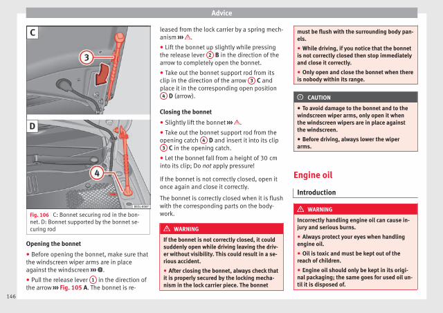
Advice
Fig. 106 C: Bonnet securing rod in the bon-net. D: Bonnet supported by the bonnet se-curing rod
Opening the bonnet
● Before opening the bonnet, make sure thatthe windscreen wiper arms are in placeagainst the windscreen ››› .
● Pull the release lever 1 in the direction ofthe arrow ››› Fig. 105 A. The bonnet is re-
leased from the lock carrier by a spring mech-anism ››› .
● Lift the bonnet up slightly while pressingthe release lever 2 B in the direction of thearrow to completely open the bonnet.
● Take out the bonnet support rod from itsclip in the direction of the arrow 3 C andplace it in the corresponding open position
4 D (arrow).
Closing the bonnet
● Slightly lift the bonnet ››› .
● Take out the bonnet support rod from theopening catch 4 D and insert it into its clip
3 C in the opening catch.
● Let the bonnet fall from a height of 30 cminto its clip; Do not apply pressure!
If the bonnet is not correctly closed, open itonce again and close it correctly.
The bonnet is correctly closed when it is flushwith the corresponding parts on the body-work.
WARNING
If the bonnet is not correctly closed, it couldsuddenly open while driving leaving the driv-er without visibility. This could result in a se-rious accident.
● After closing the bonnet, always check thatit is properly secured by the locking mecha-nism in the lock carrier piece. The bonnet
must be flush with the surrounding body pan-els.
● While driving, if you notice that the bonnetis not correctly closed then stop immediatelyand close it correctly.
● Only open and close the bonnet when thereis nobody within its range.
CAUTION
● To avoid damage to the bonnet and to thewindscreen wiper arms, only open it whenthe windscreen wipers are in place againstthe windscreen.
● Before driving, always lower the wiperarms.
Engine oil
Introduction
WARNING
Incorrectly handling engine oil can cause in-jury and serious burns.
● Always protect your eyes when handlingengine oil.
● Oil is toxic and must be kept out of thereach of children.
● Engine oil should only be kept in its origi-nal packaging; the same goes for used oil un-til it is disposed of.
146

Checking and refilling levels
● Never store engine oil in empty food con-tainers or bottles as other people may acci-dentally drink it.
● Regular contact with engine oil can be badfor the skin. If you come into contact with en-gine oil, wash your skin with soap and water.
● With the engine running, the engine oilgets extremely hot and can cause severe skinburns. Always wait until the engine has fullycooled.
For the sake of the environment
Similar to the other service liquids, spilledengine oil can be bad for the environment.Collect these liquids in suitable containersand dispose of them while respecting the en-vironment.
Warning and control lamps
FlashesPossiblecause
Solution
Engine oilpressure toolow.
Stop the vehicle!Switch off the engine. Checkthe engine oil level, and ifnecessary, refill with››› page 148.engine oil - If the warning in-dicator flashes although theoil level is correct, do notcontinue driving or leave theengine running. Otherwise,the engine could be dam-aged. Seek specialist assis-tance.
WARNING
Observe the safety warnings ››› in Controland warning lamps on page 40.
Engine oil specifications
Replacement engine oil must strictly complywith the specifications.
The correct oil must be used to ensure thecorrect operation and long service life of theengine. The engine comes with a high-qualitymultigrade oil that can generally be used allyear round.
Only use an engine oil that complies to SEATstandards whenever possible ››› . Only refillengine oil using approved engine oil in ac-cordance with the corresponding VW stand-ard (››› table on page 147). All oils indicatedare synthetic multigrade oils.
Engine oils are being continuously furtherdeveloped. Technical services are constantlyupdated with any modifications. SEAT there-fore recommends that you have the engineoil changed by a technical service.
Engines
Specifications of en-gine oil with a serv-
ice dependent ontime/distance travel-
led
44 kW - 55 kW Petrol en-gines
VW 504 00, VW 502 00
Natural gas engine VW 502 00
CAUTION
● Only use engine oils whose specificationsare expressly approved by SEAT. The use ofany other type of oil could cause engine dam-age!
● No additives should be used with engineoil. Any damage caused by the use of suchadditives would not be covered by the factorywarranty.
147
Tech
nica
l spe
cific
atio
nsA
dvic
eO
pera
tion
Saf
ety

Advice
Checking the engine oil level andtopping up
Fig. 107 Marked engine oil dipstick
Fig. 108 In the engine compartment: Engineoil filler cap.
Preparations
● Park the vehicle on flat ground so that theengine oil reading is correct.
● The engine must be hot to be able to checkthe engine oil level. Stop the engine and wait
a few minutes for the oil to drain back intothe sump.
● Open the bonnet ››› page 143.
● The engine oil filler neck can be recognisedby the symbol on the cap ››› Fig. 108 andthe dipstick by its coloured handle.
Check the engine oil level
● Pull out the dipstick and wipe it on a cleancloth.
● Replace the dipstick, pushing it in as far asit will go. If the dipstick to measure engine oilhas a mark, when you reintroduce it thismark should slot into the correspondinggroove located on the upper end of the tube.
● Remove the dipstick again and check theengine oil level ››› table on page 148.
● After reading the oil level, replace the dip-stick in the tube completely.
Engine oil topping up ranges
Fig. 107Operations required depending onthe engine oil level:
Area A Do not top up oil ››› .
Area BYou can add oil, but keep the level in thiszone.
Area COil must be added. After topping up the oillevel should be in area B .
Adding oil after checking the level
Only add engine oil in small quantities and insteps:
● Unscrew the cap from engine oil filler neckon the cylinder head ››› Fig. 108. If you arenot sure where the cap is, request help froma specialist.
● Only refill using approved SEAT engine oilin small quantities (no more than 0.5 ltr)››› page 147.
● To avoid adding too much oil, each timeyou add a quantity, wait until the oil has flow-ed into the crankcase so that it can be meas-ured with the dipstick.
● Check the oil level before adding any moreoil. Do not top up with too much engine oil››› .
● When the oil level is in at least the››› Fig. 107 B zone, insert the dipstick intothe tube fully to avoid engine oil escapingwhen the engine is running.
● After topping up the oil, ensure that thecap is screwed on to the filler neck correctly.
WARNING
Oil could catch fire if it comes into contactwith hot engine components. This could leadto a fire, explosion and severe injuries.
● Always ensure that after topping of oil, theengine oil filler cap is correctly tightened.
148

Checking and refilling levels
This will avoid engine oil spilling onto hotengine parts when the engine is running.
CAUTION
● If the engine oil level is above the area A
do not start the engine. Seek specialist assis-tance. Otherwise catalytic converter and en-gine damage may occur.
● When refilling or changing service liquids,ensure that you put the liquids into the righttank. Making a mistake when refilling couldcause serious malfunctions and damage theengine!
For the sake of the environment
The oil level must never be above area A .Otherwise oil can be drawn in through thecrankcase breather and escape into the at-mosphere via the exhaust system.
Engine oil consumption
The consumption of engine oil can be differ-ent from one engine to another and can varyduring the useful life of the engine.
Depending on how you drive and the condi-tions in which the vehicle is used, oil con-sumption can be up to 1 ltr./2000 km. In thecase of new vehicles, the consumption canexceed this figure over 5,000 kilometres. Forthis reason the engine oil level must be
checked at regular intervals, preferably whenfilling the tank and before a journey.
When the engine is working hard, for in-stance during sustained high-speed motor-way cruising in summer or when climbingmountain passes, the oil level should pref-erably be kept within area ››› Fig. 107 A .
Changing the engine oil
The engine oil must be changed regularly ac-cording to the specifications of the Mainte-nance Programme.
Due to the problems linked with disposing ofused oil and the need for suitable tools andspecial knowledge, always visit a specialisedworkshop to have the engine oil and filterchanged. SEAT recommends taking your carin for technical service.
Detailed information on the service intervalsis shown in the Maintenance Programme.
Engine oil additives make new oil darker afterthe engine has been running for a short peri-od. This is normal and does not mean morefrequent oil changes are required.
WARNING
If, in exceptional circumstances, you mustchange the engine oil yourself, please notethe following:
● Wear eye protection.
● Always wait until the engine has complete-ly cooled to avoid being burned.
● Always keep your arms horizontal when un-screwing the oil drainage bolt so that it doesnot run down your arms.
● Use a suitable container large enough tocollect all of the used oil in the engine.
● Never collect engine oil in empty food con-tainers, cans, bottles or other containers asnot all people are able to identify engine oil.
● Oil is toxic and must be kept out of thereach of children.
For the sake of the environment
Before changing the engine oil, find a suita-ble location or service for proper disposal.
For the sake of the environment
Always dispose of engine oil with the utmostrespect for the environment. Never dispose ofused engine oil in places such as a garden,woods, drains, roads, paths, rivers and drain-age systems.
149
Tech
nica
l spe
cific
atio
nsA
dvic
eO
pera
tion
Saf
ety

Advice
Engine coolant
Introduction
WARNING
Engine coolant is toxic!
● Only keep engine coolant in its originalcontainer, tightly shut and in a safe place.
● Never store engine coolant in empty foodcontainers or bottles as other people may ac-cidentally drink it.
● Always keep engine coolant out of reach ofchildren.
● Ensure that the proportion of engine cool-ant additive corresponds to the lowest out-side temperature to which the vehicle will beexposed.
● If the outside temperature is extremely low,the engine coolant could freeze causing thevehicle to stop. As this would also cause theheating to stop working, vehicle occupantswithout warm clothing could freeze.
For the sake of the environment
Coolants and additives can contaminate theenvironment. Collect any spilt fluids in suita-ble containers and dispose of them in accord-ance with legislation and with the utmost re-spect for the environment.
Coolant warning lamp
Several warning and control lamps light upfor a few seconds when the ignition is switch-ed on, signalling that the function is beingverified. They will switch off after a few sec-onds.
It lightsup
Possiblecause
Solution
Excessive en-gine coolanttemperature.
Stop the vehicle!Stop the vehicle safely assoon as possible. Switchoff the engine and let itcool.
Insufficient en-gine coolantlevel.
¡Stop the vehicle!Check the engine coolantwhen the engine hascooled and, if it is low, re-fill with engine coolant››› page 151.
Engine coolantsystem faulty.
Do not drive any fur-ther.Obtain professional as-sistance.
FlashesPossiblecause
Solution
Engine coolantsystem faulty.
Seek specialist assis-tance.
WARNING
Observe the safety warnings ››› in Controland warning lamps on page 40.
Note
On the display of the Portable NavigationSystem (supplied by SEAT) ››› page 123 an en-gine coolant temperature gauge can be seen.
Engine coolant specifications
The engine cooling system is supplied fromthe factory with a specially treated mixture ofwater and, at least, 40 % of the additive G 13(TLVW 774 J). The engine coolant additive isrecognisable by its purple colour. This mix-ture of water and additive gives the necessa-ry frost protection down to -25°C (-13 F) andprotects the light alloy parts of the coolingsystem against corrosion. It also preventsscaling and considerably raises the boilingpoint of the coolant.
To protect the engine cooling system, thepercentage of additive must always be atleast 40 %, even in warm climates where an-ti-freeze protection is not required.
If greater frost protection is required in verycold climates, the proportion of additive canbe increased. However, the percentage of ad-ditive should not exceed 60%, as this would
150

Checking and refilling levels
reduce the frost protection and, in turn, de-crease the cooling capacity.
When the coolant is topped up, use a mixtureof distilled water and, at least, 40 % of the G13 or G 12 plus-plus (TL-VW 774 G) additive(both are purple) to obtain an optimum anti-corrosion protection ››› . The mixture of G13 with G 12 plus (TL-VW 774 F), G 12 (red) orG 11 (green-blue) engine coolants will signifi-cantly reduce the anticorrosion protectionand should, therefore be avoided ››› .
WARNING
If there is not enough anti-freeze in the cool-ant system, the engine may fail leading to se-rious damage.
● Please make sure that the percentage ofadditive is correct with respect to the lowestexpected ambient temperature in the zone inwhich the vehicle is to be used.
● When the outside temperature is very low,the coolant could freeze and the vehiclewould be immobilised. In this case, the heat-ing would not work either and inadequatelydressed passengers could die of cold.
CAUTION
The original additives should never be mixedwith coolants which are not approved bySEAT. Otherwise, you run the risk of causingsevere damage to the engine and the enginecooling system.
● If the fluid in the expansion tank is not pur-ple but is, for example, brown, this indicatesthat the G 13 additive has been mixed withan inadequate coolant. The coolant must bechanged as soon as possible if this is thecase! This could result in serious faults andengine damage.
For the sake of the environment
Coolants and additives can contaminate theenvironment. If any fluids are spilled, theyshould be collected and correctly disposedof, with respect to the environment.
Checking the engine coolant level andrefilling
Fig. 109 In the engine compartment: Markingon coolant expansion tank
Fig. 110 In the engine compartment: Coolantexpansion tank cap
If the coolant level is low, the coolant warn-ing indicator will light.
Preparations
● Park the vehicle on even, flat and firmground.
● Allow the engine to cool ››› .
● Open the bonnet ››› page 143.
● The coolant expansion tank is easily recog-nisable because of the symbol on the cap››› Fig. 110.
Checking the engine coolant level
● When the engine is cold, check the coolantlevel using the side marking on the expan-sion tank ››› Fig. 109.
● If the level is below the “MIN” mark, top upwith coolant. When the engine is hot it maybe slightly above the marked area. »
151
Tech
nica
l spe
cific
atio
nsA
dvic
eO
pera
tion
Saf
ety
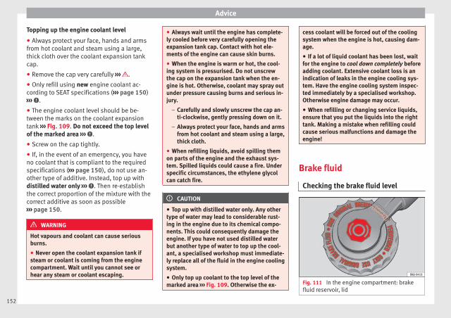
Advice
Topping up the engine coolant level
● Always protect your face, hands and armsfrom hot coolant and steam using a large,thick cloth over the coolant expansion tankcap.
● Remove the cap very carefully ››› .
● Only refill using new engine coolant ac-cording to SEAT specifications (››› page 150)››› .
● The engine coolant level should be be-tween the marks on the coolant expansiontank ››› Fig. 109. Do not exceed the top levelof the marked area ››› .
● Screw on the cap tightly.
● If, in the event of an emergency, you haveno coolant that is compliant to the requiredspecifications (››› page 150), do not use an-other type of additive. Instead, top up withdistilled water only ››› . Then re-establishthe correct proportion of the mixture with thecorrect additive as soon as possible››› page 150.
WARNING
Hot vapours and coolant can cause seriousburns.
● Never open the coolant expansion tank ifsteam or coolant is coming from the enginecompartment. Wait until you cannot see orhear any steam or coolant escaping.
● Always wait until the engine has complete-ly cooled before very carefully opening theexpansion tank cap. Contact with hot ele-ments of the engine can cause skin burns.
● When the engine is warm or hot, the cool-ing system is pressurised. Do not unscrewthe cap on the expansion tank when the en-gine is hot. Otherwise, coolant may spray outunder pressure causing burns and serious in-jury.
– Carefully and slowly unscrew the cap an-ti-clockwise, gently pressing down on it.
– Always protect your face, hands and armsfrom hot coolant and steam using a large,thick cloth.
● When refilling liquids, avoid spilling themon parts of the engine and the exhaust sys-tem. Spilled liquids could cause a fire. Underspecific circumstances, the ethylene glycolcan catch fire.
CAUTION
● Top up with distilled water only. Any othertype of water may lead to considerable rust-ing in the engine due to its chemical compo-nents. This could consequently damage theengine. If you have not used distilled waterbut another type of water to top up the cool-ant, a specialised workshop must immediate-ly replace all of the fluid in the engine coolingsystem.
● Only top up coolant to the top level of themarked area ››› Fig. 109. Otherwise the ex-
cess coolant will be forced out of the coolingsystem when the engine is hot, causing dam-age.
● If a lot of liquid coolant has been lost, waitfor the engine to cool down completely beforeadding coolant. Extensive coolant loss is anindication of leaks in the engine cooling sys-tem. Have the engine cooling system inspec-ted immediately by a specialised workshop.Otherwise engine damage may occur.
● When refilling or changing service liquids,ensure that you put the liquids into the righttank. Making a mistake when refilling couldcause serious malfunctions and damage theengine!
Brake fluid
Checking the brake fluid level
Fig. 111 In the engine compartment: brakefluid reservoir, lid
152

Checking and refilling levels
In the course of time, the brake fluid absorbswater from the ambient air. If there is toomuch water in the brake fluid, the brake sys-tem could be damaged. In addition, the boil-ing point of the brake fluid is significantlylowered. When the brake fluid contains toomuch water and the brakes are subject toconsiderable forces, bubbles of water vapourcan form in the system. These bubbles cansignificantly reduce braking power, notablyincreasing braking distance, and could evenresult in the total failure of the brake system.Ensuring that the brake system is alwaysfunctioning correctly is essential for your ownsafety and the safety of other road users››› .
Brake fluid specifications
SEAT have developed a special brake fluidoptimised for the brake systems of their vehi-cles. To ensure the optimum working of thebrake system, SEAT recommends the use ofbrake fluid in accordance with the VW 501 14standard. If this brake fluid is not available oranother brake fluid is used for different rea-sons, use a brake fluid that complies with theUnited States standard FMVSS 116 DOT 4 orthe German standard DIN ISO 4925 CLASS 4››› .
Brake fluids conforming to the standardVW 501 14, fulfil the American requirementsof the FMVSS 116 DOT 4 standard and theGerman DIN ISO 4925 CLASS 4 standard.
However, fluids that comply with the Ameri-can FMVSS 116 DOT 4 standard or the Ger-man DIN ISO 4925 CLASS 4 standard do notnecessarily comply with the VW 501 14standard. Always check the information onthe brake fluid container and ensure that youare using suitable brake fluid.
A suitable brake fluid can be obtained fromSEAT dealerships.
Brake fluid level
The level of the brake fluid should always bebetween the MIN and MAX marks, or abovethe MIN mark ››› .
It is not always possible to check the level ofthe brake fluid, as in some models the en-gine components make it difficult to see thebrake fluid reservoir. If you cannot read theexact brake fluid level, consult a specialist.
The brake fluid level drops slightly when thevehicle is being used due to wear of thebrake pads and the automatic readjustmentof the brake.
Changing the brake fluid
The brake fluid should be changed in accord-ance with the instructions given in the Main-tenance Programme. Have the brake fluidchanged by a specialised workshop. SEATrecommends taking your car in for technicalservice. This means that only brake fluid
complying with the required specificationswill be used.
WARNING
If the brake fluid level is low or unsuita-ble/old brake fluid is used, the brake systemmay fail or braking power may be reduced.
● Check the brake system and the brake fluidlevel regularly!
● The brake fluid should be changed regular-ly in accordance with the instructions givenin the Maintenance Programme.
● When the brake fluid is used and brakesare subjected to extreme braking forces, bub-bles of vapour form in the brake system.These bubbles can significantly reduce brak-ing power, notably increasing braking dis-tance, and could result in the total failure ofthe brake system.
● Always ensure that you use suitable brakefluid. Only used brake fluid that conforms tothe VW 501 14 standard, FMVSS 116 DOT 4standard or even the DIN ISO 4925 CLASS 4standard. Other types of brake fluid could af-fect brake operation and reduce braking pow-er. Do not use a brake fluid if the containerdoes not specify compliance with theVW 501 14, FMVSS 116 DOT 4 orDIN ISO 4925 CLASS 4 standards.
● The replacement brake fluid must be new.
WARNING
Brake fluid is poisonous. »153
Tech
nica
l spe
cific
atio
nsA
dvic
eO
pera
tion
Saf
ety

Advice
● To reduce the risk of poisoning, do not keepbrake fluid in drinks bottles/containers orsimilar. Other people could drink from theserecipients even if the contents are clearlymarked.
● Always keep brake fluid in the original con-tainer; keep it correctly sealed and out ofreach of children.
CAUTION
Brake fluid damages the vehicle paintwork.Wipe off any brake fluid from the paintworkimmediately.
For the sake of the environment
Brake fluid is an environmental pollutant.Collect any spilt service fluids and allow aprofessional to dispose of them.
Checking and topping up thewindscreen washer reservoir withwater
Fig. 112 In the engine compartment: wind-screen washer reservoir top
Check the water level in the windscreenwasher reservoir regularly and top up as re-quired.
● Open the bonnet ››› page 143.
● The washer reservoir is marked with thesymbol on the lid ››› Fig. 112.
● Check there is enough water in the reser-voir.
● To top up, mix water with a window cleanerrecommended by SEAT ››› . Please followthe instructions for use found on the packag-ing.
● In cold weather, a special antifreeze shouldalso be added to prevent the water fromfreezing ››› .
Reservoir capacity
The washer bottle capacity is approximately 3litres.
WARNING
Never mix an unsuitable antifreeze or othersimilar additives with the windscreen washerwater. A greasy layer may be formed on thewindscreen which will impair visibility.
● Use clean water with a window cleaner rec-ommended by SEAT.
● If necessary, add a suitable antifreeze tothe water in the reservoir.
CAUTION
● Do not mix cleaning products recommen-ded by SEAT with other products. This couldlead to flocculation and may block the wind-screen washer jets.
● When topping up service fluids, make abso-lutely certain that you fill the fluids into thecorrect reservoirs. Using the wrong fluidscould cause serious malfunctions and enginedamage!
Vehicle battery
Introduction
The battery is a component of the vehicle'selectrical system.
154

Checking and refilling levels
Never work on the electrical system withoutfully understanding the operations required,the applicable safety standards and withoutthe correct tools ››› ! If required, have anywork carried out by a specialised workshop.SEAT recommends taking your car in for tech-nical service. Negligent work can cause seri-ous injury.
Location of the vehicle battery
The battery is located in the engine compart-ment.
Explanation of the warning indications onthe vehicle's battery
Symbol Meaning
Wear eye protection!
Battery acid is very corrosive and caustic.Always wear protective gloves and eyeprotection!
Fires, sparks, open flames and smokingare prohibited.
A highly explosive mixture of gases is re-leased when the battery is under charge.
Keep children away from acid and batter-ies!
WARNING
Working on the vehicle battery and the elec-trical system can cause corrosion, fire and
electric shocks. Always read and take into ac-count the following warnings and safetystandards before carrying out any work:
● Before working on the battery, switch offthe engine, the ignition and all electrical de-vices then disconnect the negative connec-tion on the battery.
● Keep children away from acid and the bat-tery itself!
● Wear eye protection.
● Battery acid is very corrosive and caustic. Itcan burn skin and cause blindness. Whenhandling the battery, protect yourself fromsplashes of acids, above all your hands, armsand face.
● Do not smoke and never work close to pla-ces exposed to flames or sparks.
● Avoid sparks and electrostatic dischargeswhen working with cables and electrical devi-ces.
● Never short the battery terminals.
● Never use a damaged battery. It can ex-plode. Replace a damaged battery immedi-ately.
● Replaced damaged or frozen batteries assoon as possible. A flat battery can alsofreeze at temperatures close to 0 °C (+32 °F).
CAUTION
● Never disconnect the battery if the ignitionis switched on or if the engine is running.
This could damage the electrical system orelectronic components.
● Do not expose the battery to direct sunlightover a long period of time, as the intense ul-traviolet radiation can damage the batteryhousing.
● If the car is left standing for long periods,protect the battery from extreme cold temper-ature so that it does not “freeze up” and be-come damaged.
Warning lamp
Itlights
up
Possiblecause
Solution
Faulty generator.
Contact a specialisedworkshop. Have the elec-trical system checked.Disconnect any unneces-sary electrical devices.The generator does notcharge the battery whilethe vehicle is in motion.
Several warning and control lamps light upfor a few seconds when the ignition is switch-ed on, signalling that the function is beingverified. They will switch off after a few sec-onds. »
155
Tech
nica
l spe
cific
atio
nsA
dvic
eO
pera
tion
Saf
ety

Advice
WARNING
Observe the safety warnings ››› in Controland warning lamps on page 40.
Checking the electrolyte level of thevehicle battery
Fig. 113 In the engine compartment: Removethe cover from the vehicle's battery.
The battery's electrolyte level should bechecked regularly in high-mileage vehicles,in hot countries and in older batteries. Otherbatteries do not require maintenance.
Vehicles fitted with the Start-Stop system areequipped with special batteries. For technicalreasons, the electrolyte level cannot bechecked in these batteries.
Preparations
● Prepare the vehicle for work in the enginecompartment ››› page 143
● Open the bonnet ››› page 143.
● Press on the tabs ››› Fig. 113 (arrows) in thedirection of the arrows and lift the batterycover up.
Checking the battery electrolyte level
● Make sure there is sufficient lighting toclearly recognise the colours. Never useflames or shiny objects as a light source.
● Depending on the level of acid, the Magiceye on the top of the battery will change col-our.
Colour in-dicator
Necessary operations
Light yellowor colourless
The electrolyte level of the vehicle's bat-tery is too low. Have the battery checkedand, where applicable, replaced by aspecialised workshop.
BlackThe electrolyte level of the vehicle's bat-tery is correct.
WARNING
Working with the vehicle battery involves arisk of corrosion, explosions and electricshock.
● Never tilt the vehicle battery. Battery acidcould spill out of the openings for the releaseof gases and cause corrosion damage.
● Never open the vehicle battery.
● If battery acid splashes on you, immediate-ly rinse your eyes and skin abundantly withwater for several minutes. Then seek medicalcare immediately.
● If acid is swallowed by mistake, consult adoctor immediately.
Charging, replacing and connecting ordisconnecting the battery
Charging the battery
The vehicle battery should be charged by aspecialised workshop only, as batteries us-ing special technology have been installedand they must be charged in a controlled en-vironment ››› . SEAT recommends takingyour car in for technical service.
Replacing a vehicle battery
The battery has been developed to suit theconditions of its location and has specialsafety features. If the battery must be re-placed, consult a technical service for infor-mation on electromagnetic compatibility, thesize and maintenance, performance andsafety requirements of the new battery inyour vehicle before you purchase one. SEAT
156

Checking and refilling levels
recommends you have the battery replacedby a technical service.
Use only maintenance-free genuine batteriesconforming to TL 825 06 and VW 7 50 73Standards. These standards must be datedApril 2008 or later.
Vehicles fitted with the Start-Stop system areequipped with a special battery. Therefore,this battery must only be replaced by anotherwith the same specifications.
Disconnecting the vehicle's battery
If you must disconnect the battery from theelectrical system, please note the following:
● Switch off the ignition and all electricalequipment.
● The vehicle must be unlocked before dis-connecting the battery, otherwise the alarmwill be triggered.
● First disconnect the negative cable andthen the positive ››› .
Connecting the vehicle's battery
● Before reconnecting the battery, switch offthe engine and all electrical devices.
● First reconnect the positive cable and thenthe negative ››› .
Different control lamps may light up afterconnecting the battery and switching the ig-nition on. They will be turned off after a short
trip at a speed of between 15-20 km/h(10-12 mph). If the warning indicators remainlit, please visit a specialised workshop tohave the vehicle checked.
If the battery has been disconnected for along time, it is possible that the next servicedate is not displayed or calculated correctly››› page 36. Respect the maximum service in-tervals permitted ››› Booklet MaintenanceProgramme.
Automatic device disconnection
The intelligent vehicle electrical system auto-matically implements a range of measures toprevent the battery from discharging whenhigh demands are made on it:
● The idling speed is increased so that the al-ternator provides more electricity.
● Where necessary, the power to the mostpowerful devices is reduced or even com-pletely disconnected.
● On starting the engine, the power supplyfrom the 12-volt power sockets and the ciga-rette lighter may be interrupted for a shorttime.
The on-board management program cannotalways prevent the battery from running flat.For example, if the ignition is left on for along period with the engine off or if the sidelights or parking lights are left on while thevehicle is stationary.
Why the battery runs flat:
● When stationary for a long time withoutstarting the engine, particularly if the ignitionis switched on.
● Use of electrical devices with the engineswitched off.
WARNING
Incorrectly securing the battery or using thewrong battery can cause short-circuits, fireand serious injuries.
● Always use only maintenance-free batter-ies, protected to prevent a leak, and whoseproperties, specifications and size corre-spond to the standard battery.
WARNING
A highly explosive mixture of gases is re-leased when the battery is under charge.
● The batteries should be charged in a well-ventilated room only.
● Never charge a frozen or recently thawedbattery. A flat battery can also freeze at tem-peratures close to 0 °C (+32 °F).
● Always replace a battery which has frozen.
● Battery cables not correctly connected maycause a short circuit. Reconnect first the posi-tive cable and then the negative cable. »
157
Tech
nica
l spe
cific
atio
nsA
dvic
eO
pera
tion
Saf
ety

Advice
CAUTION
● Never disconnect the battery if the ignitionis switched on or if the engine is running.This could damage the electrical system orelectronic components.
● Never plug accessories that supply current,such as solar panels or a battery charger, tothe 12-volt power socket or the cigarettelighter. This could damage the vehicle's elec-trical system.
For the sake of the environment
Dispose of the battery in an environment-friendly manner. Batteries contain toxic sub-stances such as sulphuric acid and lead.
For the sake of the environment
Battery acid can contaminate the environ-ment. Collect any spilt service fluids and dis-pose of them correctly.
Wheels and tyres
Wheels
Introduction
SEAT recommend that all work on tyres andwheels is carried out by a specialised work-shop. These workshops have the necessaryspecial tools and replacement parts, trainedpersonnel and facilities for disposing of theold tyres while respecting the environment.SEAT recommends taking your car in for tech-nical service.
WARNING
The vehicle cannot be totally controlled orbraked if the tyres (new or used) are worn ordamaged.
● Incorrect use of wheels and tyres couldmake driving more dangerous and result inserious accidents and damage.
● All four wheels must be fitted with radialtyres of the same type, size (rolling circumfer-ence) and the same tread pattern.
● New tyres do not give maximum grip andwill not have reached their maximum brakingcapacity to start with, and therefore needrunning in. To prevent accidents and majordamage, extreme caution should be taken forthe first 600 km.
● Check tyre pressures regularly and ensurethey are maintained at the pressures indica-ted. If the tyre pressure is too low, they couldoverheat, resulting in tread detachment oreven burst tyres.
● Never drive on damaged (punctured, cut,cracked or dented) or worn tyres. Driving ondamaged or worn tyres could result in bursttyres, serious accidents or damage. Worn ordamaged tyres must be replaced immediate-ly.
● Never exceed the maximum permittedspeed or loads specified for the type of tyrefitted on your vehicle.
● The effectiveness of driver and brake assistsystems also depends on the grip of thetyres.
● If you notice unusual vibration or if the ve-hicle pulls to one side when driving, stop thecar immediately and check the tyres andwheels for damage.
● To minimise the risk of losing control of thevehicle or causing a serious accident, neverundo the bolted joints of beadlock wheels.
● Never mount used tyres or wheels if you arenot sure of their previous history. They maybe damaged, although the damage is not im-mediately visible.
● Old tyres, even if they have never beenused, may lose air or burst unexpectedlywhile driving, especially at high speeds, re-sulting in serious accident and injury. If tyresare over six years old, they should only beused in an emergency and with extreme cau-tion.
158

Wheels and tyres
Note
For technical reasons, it is not generally pos-sible to use the wheels from other vehicles.In some cases, this may also be true for thesame model of wheel. Please refer to the ve-hicle documentation or ask at a technicalservice.
About your tyres and wheels
Fig. 114 Diagram for changing wheels
The tyres of a vehicle are the componentswhich are subjected to most stress and arethe most underestimated. Tyres are very im-portant, as the support offered by their nar-row surface is the only point of contact be-tween the vehicle and the road.
The service life of tyres is dependent on tyrepressure, driving style, the care they receiveand the correct fitting.
The tyres and wheel rims are an essentialpart of the vehicle's design. The tyres andrims approved by SEAT are specially matchedto the characteristics of the vehicle and ourcritical to good road holding and safe han-dling.
Avoiding damage to tyres and wheels
● If you have to drive over a kerb or similarobstacle, drive very slowly and as near aspossible at a right angle to the kerb.
● Inspect the tyres regularly for damage(punctures, cuts, cracks, dents).
● Remove any foreign bodies found on theoutside of the tyre tread and ensure that theyhave not passed through the wall of the tyre››› page 163.
● In addition, the instructions for tyre controlsystems should always be observed.
● Replace damaged or worn tyres as soon aspossible ››› page 163.
● Regularly check tyres for non-visible dam-age ››› page 163.
● Never exceed the maximum permittedspeed or loads specified for the type of tyrefitted on your vehicle ››› page 167.
● Do not allow tyres (including the sparewheel) to come into contact with aggressivesubstances, grease, oil, fuel or brake fluid››› .
● Lost valve caps should be replaced imme-diately.
Tyres with directional tread pattern
Tyres with directional tread pattern havebeen designed to operate best when rotatingin only one direction. An arrow on the tyresidewall indicates the direction of rotation ontyres with directional tread ››› page 167. Al-ways observe the direction of rotation indica-ted when mounting the wheel. This guaran-tees optimum grip and helps to avoid aqua-planing, excessive noise and wear.
If the tyre is mounted in the opposite direc-tion of rotation, drive with extreme caution,as the tyre is no longer being used correctly.This is of particular importance when theroad surface is wet. Change the tyre as soonas possible or remount it with the correct di-rection of rotation.
Interchanging tyres
To ensure that the wear is equal on all tyresthe wheels should be changed round fromtime to time according to the system››› Fig. 114. The useful life of all the tyres willthen be about the same time.
SEAT recommends you take the vehicle to aspecialised workshop to have the tyreschanged. »
159
Tech
nica
l spe
cific
atio
nsA
dvic
eO
pera
tion
Saf
ety

Advice
Tyres that are over 6 years old
Tyres are subject to an ageing process as aresult of physical and chemical processes.This may affect their performance. Tyreswhich are stored for long periods of timewithout being used, harden and becomemore fragile than tyres which are in constantuse.
SEAT recommends that tyres over six yearsold are replaced with new tyres. This also ap-plies to tyres (including the spare wheel)which appear to be in perfect condition onthe outside and which have a tread depthwithin the values stipulated by the Law ››› .
The date of manufacture, part of the tyreidentification number (TIN), indicates the ageof the tyre () ››› page 167.
Storing tyres
Mark tyres when you remove them to indicatethe direction of rotation (left, right, forwards,backwards). This ensures you will be able tomount them correctly when you replacethem. When removed, the wheels and/ortyres should be stored in a cool, dry and pref-erably dark location. Do not place tyresmounted on the wheel in a vertical position.
Protect tyres not mounted on wheels fromdirt by storing them in suitable bags andstanding them on the ground on their tread.
WARNING
Aggressive fluids or substances could resultin visible or invisible damage with the conse-quent risks.
● Always ensure that tyres do not come intocontact with chemical products, oil, grease,fuel, brake fluid or other aggressive substan-ces.
WARNING
Old tyres, even if they have never been used,may lose air or burst unexpectedly while driv-ing, resulting in serious accident or damage.
● If tyres are over six years old, they shouldonly be used in an emergency and with ex-treme caution.
For the sake of the environment
Old tyres must be disposed of by qualifiedpersonnel according to the laws in the coun-try concerned.
Wheel rims
The design of wheel bolts is matched to therims. If different rims are fitted, the correctwheel bolts with the right length and correct-ly shaped bolt heads must be used. This en-sures that wheels are fitted securely and thatthe brake system functions correctly››› page 174.
For technical reasons, it is not generally pos-sible to use the wheels from other vehicles.In some cases, this may also be true for thesame model of wheel.
The tyres and rims approved by SEAT are spe-cially matched to the characteristics of thevehicle and are critical to good road holdingand safe handling.
Note for Italy: A SEAT Service Centre shouldbe consulted whether different sized wheelsor tyres to those originally fitted by SEAT maybe fitted, as well as the combinations al-lowed between the front axle (axle 1) andback axle (axle 2).
Wheel bolts
Wheel bolts must be tightened to the correcttorque ››› page 174.
Beadlock wheel rims
Beadlock wheel rims have various compo-nents. These are joined together by specialbolts using a special procedure. This ensuresgood performance, a better seal, improvedsafety and wheel run out. Therefore, wornrims should always be replaced and must on-ly be repaired in a specialised workshop.SEAT recommends visiting a technical service››› .
160

Wheels and tyres
Wheel rims with bolted trims
Wheel rims may be fitted with interchangea-ble trim parts which are attached to the rimusing self-locking bolts. Worn trims shouldonly be replaced at a specialised workshop.SEAT recommends visiting a technical service››› .
WARNING
The use of worn or damaged wheel rims couldmake driving more dangerous and result inserious accidents and damage.
● Only wheel rims which have been approvedfor use with your vehicle should be used.
● Inspect wheel rims regularly for damageand replace as required.
WARNING
If the bolted joints of wheel rims with boltedring trims are not correctly tightened or loos-ened, this could result in serious accident.
● Never loosen the bolted joints of wheelrims with bolted ring trims.
● Any work relating to wheel rims with boltedrims should be carried out at specialisedworkshop. SEAT recommends taking your carin for technical service.
Replacement of wheel rims and newtyres
New tyres
● When tyres are new, drive with extremecaution for the first 600 km, as all tyres needto be run-in. Tyres which have not been run-in do not have such good grip ››› or brak-ing capacity ››› .
● All four wheels must be fitted with radialtyres of the same type, size (rolling circumfer-ence) and the same tread pattern.
● The tread depth of new tyres may vary, ac-cording to the type and make of tyre and thetread pattern.
Replacing tyres
● Where possible, always replace bothwheels on an axle (both wheels on the frontaxle or both wheels on the rear axle) ››› .
● Only replace used tyres with those author-ised by SEAT for the corresponding type vehi-cle. Pay special attention to size, diameter,and maximum load and speed capacity.
● Never use tyres which are larger than SEATapproved tyres. If the tyres are too big, theymay knock or rub against the chassis or othercomponents, resulting in damage.
WARNING
New tyres do not give maximum grip and willnot have reached their maximum braking ca-pacity to start with, and therefore need run-ning in.
● To prevent accidents and major damage,extreme caution should be taken for the first600 km.
WARNING
There should be adequate space between thetyres and the vehicle in accordance with thevehicle design. If this is not the case, thetyres may rub against parts of the runninggear, chassis or brake lines, leading to faultsin the brake system or to tread detachment,and the risk of burst tyres.
● The true tyre dimension should not begreater than the dimensions of tyres manu-factured and approved by SEAT and shouldnot rub against parts of the vehicle.
Note
Although tyres may be shown as being thesame size, the true dimensions of differenttypes of tyre may vary with respect to thenominal size, or tread patterns may be differ-ent.
Note
If you use tyres that are approved by SEAT,you can be sure that the true tyre dimensions »
161
Tech
nica
l spe
cific
atio
nsA
dvic
eO
pera
tion
Saf
ety

Advice
will be correct for your vehicle. For other tyremodels, the tyre vendor should provide themanufacturer's certificate with the tyre, indi-cating that this type of tyre is suitable foryour vehicle. This certificate should alwaysbe carried with the vehicle.
Tyre pressures
Fig. 115 Position of tyre pressure specifica-tion plate
The correct tyre pressures for tyres fitted atthe factory is shown on a label and is validfor summer and winter tyres. The label
››› Fig. 115 is located on the driver's door pil-lar.
Under-inflation or over-inflation will reducethe life of the tyres considerably and also im-pair the car's handling ››› . It is essential tomaintain the correct tyre pressures, especial-ly if driving at high speeds. Incorrect tyrepressure causes premature wear and couldcause tyre blow-out.
The pressure should therefore be checked atleast once a month and before starting ajourney.
As a general rule, the pressures given are forcold tyres. When the tyres are hot, the pres-sures are greater.
Never deflate a hot tyre in order to obtain therequired pressure. This could result in verylow tyre pressures which may lead to suddenblow-outs.
Checking tyre pressures
Check tyre pressures only when the vehiclehas not been driven for more than a few kilo-metres at low speeds in the past three hours.
● The tyre pressures should be checked regu-larly, and only when the tyres are cold. Al-ways check all tyres, including the sparewheel. Tyre pressures should be checkedmore often in colder regions, and only whenthe vehicle has not been driven recently. Al-ways use a correctly-operating tyre gauge.
● Adjust tyre pressures to the loads carried inthe vehicle.
● After adjusting the tyre pressure, check thatthe caps are properly screwed on.
The spare wheel or temporary spare wheelmust be at the maximum pressure specified.
WARNING
If tyre pressures are too high or too low, thetyre may deflate or burst suddenly while driv-ing. This could result in a serious accident.
● If the tyre pressure is too low, they couldoverheat, resulting in tread detachment oreven burst tyres.
● When driving at high speeds and/or fullyloaded, the tyre could suddenly overheat,burst or be subject to tread detachment, withthe resultant loss of control of the vehicle.
● Tyre pressures which are too high or toolow reduce the service life of the tyre, affect-ing the vehicle's performance.
● Tyre pressures should be checked regularly,at least once a month and before long jour-neys.
● Adjust the pressures of all the tyres to thevehicle load.
● Never deflate excess pressure from hottyres.
162

Wheels and tyres
CAUTION
● Take care not to tilt the manometer whenplacing it on the valve. Otherwise, the valvemay be damaged.
● If tyre valves are not protected by caps, or ifthe caps are not screwed on correctly, theymay become damaged. Check that the capsare identical to the standard caps and havebeen correctly tightened.
For the sake of the environment
Under-inflated tyres will increase fuel con-sumption.
Tread depth and wear indicators
Fig. 116 Tyre tread: tread wear indicators
Tread depth
Certain driving conditions require a deepertread, as well as needing the tread to be ap-
proximately the same on the front and reartyres. This is particularly important whendriving in winter, in cold temperatures and onwet roads ››› .
The minimum tread depth required by law inthe majority of cases is 1.6 mm, measured inthe tread grooves next to the tread wear indi-cators. Observe legal requirements in eachcountry.
The performance of winter tyres is much re-duced when the tread has worn to 4 mm.
The tread depth of new tyres may vary, ac-cording to the type and make of tyre and thetread pattern.
Wear indicators on the tyre
The original tyres on your vehicle have1.6 mm high ››› Fig. 116 tread wear indicatorsrunning across the tread. A number of theseindicators are equally spaced around the tyretread. Certain marks on the tyre walls (e.g.the letters “TWI” or other symbols) indicatethe position of the wear indicators.
Tread wear indicators indicate if a tyre isworn. They must always be replaced beforethe tyre tread has worn to the level of the in-dicator.
WARNING
Driving with worn tyres is dangerous, andmay lead to loss of control of the vehicle withserious consequences.
● Tyres must be replaced before the wear in-dicators are at the same level as the treadpattern.
● Worn tyres have significantly reduced grip,especially on wet surfaces, increasing therisk of “aquaplaning”.
● Worn tyres make control of the vehiclemore difficult in normal or difficult drivingconditions, increasing the braking distanceand the risk of skidding.
Damaged tyres
Damage to wheels and tyres is often not im-mediately visible. If you notice unusual vibra-tion or the car pulling to one side, this mayindicate that one of the tyres is damaged››› .
● Slow down immediately if you think youhave a damaged wheel.
● Check the wheels and tyres for damage.
● If tyres are worn, stop driving and seekqualified assistance.
● If there is no visible exterior damage, driveslowly and carefully to the nearest special-ised workshop and have the vehicle checked. »
163
Tech
nica
l spe
cific
atio
nsA
dvic
eO
pera
tion
Saf
ety

Advice
Foreign bodies in the tyre
● Do not remove foreign bodies if they havepenetrated through the tyre wall!
● You should obtain professional assistanceimmediately.
Wear of tyres
The wear of tyres depends on a number offactors, for example:
● Driving style.
● Unbalanced wheels.
● Running gear settings.
Driving style: Driving round bends quickly orsudden acceleration or braking speed accel-erates tyre wear. When the driving style isnormal, if the tyres wear too quickly, have therunning gear settings checked at a special-ised workshop.
Wheel run-out: The wheels on new vehiclesare balanced. However, certain circumstan-ces may lead to imbalance (run-out), which isdetected as vibrations in the steering wheel.Run-out leads to wear of the steering andsuspension. In the event of run out, thewheels should be balanced again. When anew wheel is fitted, it should be balancedagain.
Running gear settings: an incorrectly posi-tioned running gear increases the wear oftyres and affects your safety while driving. If
tyres wear too quickly, have the wheel align-ment checked at a specialised workshop.
WARNING
If you notice unusual vibration or the car pullsto one side while driving, this may indicatethat one of the tyres is damaged.
● Reduce speed immediately and stop, whileobserving the highway code.
● Check the wheels and tyres for damage.
● Never carry on driving on worn tyres orwheels. Request qualified assistance immedi-ately.
● If there is no visible exterior damage, driveslowly and carefully to the nearest special-ised workshop and have the vehicle checked.
Tyre monitoring system*
Fig. 117 Centre console: tyre monitor systembutton
The tyre control lamp compares wheel revolu-tions and with it, the wheel diameter of eachwheel using the ESC. If the diameter of awheel changes, the tyre control lamp lights up. The wheel diameter changes when:
● Tyre pressure is insufficient.
● The tyre structure is damaged.
● The vehicle is unbalanced because of aload.
● The wheels of one axle are under morepressure (for example, driving with a trailer oron steep slopes).
● The vehicle is fitted with snow chains.
● The temporary spare wheel is fitted.
● The wheel on one axle is changed.
Tyre pressure adjustment
On adjusting tyre pressure or changing oneor more wheels, the ››› Fig. 117 button mustbe kept pressed down, with the ignition on,until an acoustic signal is heard.
If the wheels are under excessive load (for ex-ample, driving with a trailer or heavy load),the tyre pressure must be increased to therecommended value for a full load (see thesticker on the inside of the fuel flap). If thetyre monitor system button is pressed down,the new tyre pressures are confirmed.
164

Wheels and tyres
The tyre pressure control lamp lights up
If the tyre pressure of a wheel is much lowerthan the value set by the driver, then the tyrepressure control lamp ››› will light up.
WARNING
● When the tyre pressure control lamp lightsup, reduce speed immediately and avoid anysudden turning or braking manoeuvre. Stopwhen possible, and check the tyre pressureand status.
● The driver is responsible for maintainingcorrect tyre pressures. For this reason, tyrepressure must be regularly checked.
● Under certain circumstances (e.g. whendriving in a sporty manner, in winter condi-tions or on a dirt track) the tyre control lampmay light up belatedly or may function incor-rectly.
Note
If the battery is disconnected, the yellowwarning lamp lights up after turning theignition on. This should turn off after a briefjourney.
Spare wheel or temporary sparewheel*
Fig. 118 In the luggage compartment: handcontrolled wheel for securing the spare wheel
Removing the spare wheel
● Open the rear lid and lift the luggage com-partment shelf ››› page 73.
● If necessary, remove the boot variable floor››› page 73.
● Lift up the carpet from the recess and re-move it from the luggage compartment.
● If necessary, take out the vehicle tool kitwith the container.
● Completely remove the hand controlledwheel from the centre of the spare wheel››› Fig. 118 by turning it in an anticlockwisedirection, and take out the spare wheel.
Storing the replaced wheel
● Pull back the carpet.
● With the wheel rim facing downwards, sit-uate the replaced wheel in the spare wheelwell so that the wheel rim central hole coin-cides with the opening.
● Turn the hand controlled wheel with theshank screwed clockwise until the replacedwheel is secured.
● If necessary, store the vehicle tool in thecontainer, inside the boot.
● Replace the carpet on the boot floor.
● Lower the rear shelf.
● Close the rear lid.
If the spare wheel is different to the rest ofthe vehicle tyres
If the spare tyre is not the same as the tyresthat are mounted on the vehicle - for examplewith winter tyres or the temporary sparewheel - you should only use the spare tyre fora short period of time and drive with extracare ››› .
Refit the normal road wheel as soon as possi-ble.
Please observe driving advice:
● Do not drive faster than 80 km/h (50 mph).
● Avoid heavy acceleration, hard braking andfast cornering. »
165
Tech
nica
l spe
cific
atio
nsA
dvic
eO
pera
tion
Saf
ety

Advice
● Snow chains on the temporary spare wheelare not permitted ››› page 169.
● After mounting the spare wheel or the tem-porary spare wheel, check the tyre pressureas soon as possible ››› page 162.
It is advisable to check the spare wheel ortemporary spare wheel tyre pressure whenchecking the rest of the vehicle wheels atleast once a month. The spare wheel shouldhave the highest pressure allowed for the ve-hicle ››› page 162. The sticker situated on thetemporary spare wheel shows the tyre pres-sure.
WARNING
Incorrect handling of the spare wheel or thetemporary spare wheel can cause loss of ve-
hicle control, producing collisions or otherserious accidents and injury.
● Never use the spare wheel or the temporaryspare wheel if it is damaged or worn to thewear indicator.
● In some vehicles the spare wheel is smallerthan the original tyres. This can be seen on asticker showing the text “80 km/h” and“50 mph”. This text indicates the maximumvelocity permitted for this type of tyre.
● Never drive faster than 80 km/h (50 mph).Avoid powerful acceleration, hard brakingand taking corners at high speed.
● Never drive more than 200 km with a tem-porary spare wheel fitted to the drive axle.
● Replace the temporary spare wheel for anormal wheel as soon as possible. The com-pact temporary spare wheel is only intendedfor temporary use over short distances.
● The temporary spare wheel must always besecured with the factory supplied wheelbolts.
● You should never use more than one tem-porary spare wheel.
● After mounting the temporary spare wheel,check the tyre pressure as soon as possible››› page 162.
● Snow chains on the temporary spare wheelare not permitted.
Note
Wherever possible, secure the spare wheel,temporary spare wheel or the replaced wheelsafely in the luggage compartment. In vehi-cles with anti-puncture kit, it is not possibleto secure the defective wheel.
166

Wheels and tyres
Tyre code
Fig. 119 Universal code on tyres
Radial
Rim diameter code
Load index & speed rating
DOT tyre identification number
Severe snow conditions
Tyre ply composition and materials used
Max. load rating
Treadwear, traction and temperaturegrades
Max. permissible inflation pressure
Passenger car tyre
Nominal width of tyre in millimetres
Ratio of height to width (aspect ratio)
1
2
3
4
5
6
7
8
9
10
11
12
Tyre code (example) Meaning
Make, logotype Manufacturer
Product name Name of tyre assigned by manufacturer.
P255 / 55 R 18 Size:
P Passenger vehicle code.
255 Nominal width between walls, in mm.
55 Height/width ratio in %
R Tyre type (R indicates "radial").
18 Rim diameter in inches »
167
Tech
nica
l spe
cific
atio
nsA
dvic
eO
pera
tion
Saf
ety

Advice
Tyre code (example) Meaning
109 H Load index ››› page 169 and speed rating ››› page 169.
XL Reinforced tyres (“Reinforced”).
M+S or M/S or Winter tyres code (mud and snow tyres).
RADIAL TUBELESS Radial tyre without inner tube.
E4 ... E-mark certifying tyre complies with international legislation followed by a number denoting the country granting the au-thorisation. The authorisation number ( several digits) is shown below.
DOT BT RA TY5 1709 Tyre identification number (TINa), may be only on interior wall of wheel) and date of manufacture:
DOT The tyre complies with the legal requirements of the US Department of Transport, responsible for tyresafety regulations.
BT Place of manufacture code.
RA Information about manufacturer and tyre size.
TY5 Manufacturer's tyre specifications.
1709 Date of manufacture: Week 17 of 2009.
TWI This identifies the position of the Tread Wear Indicator ››› page 163.
Made in Germany Country of manufacture.
MAX LOAD 615 KG US load rating, indicating maximum permitted load per tyre.
MAX INFLATION 350 KPA (51 PSI) US limit, indicating maximum permitted tyre pressure.
SIDEWALL 1 PLY RAYON Information about tyre wall components:1 layer of rayon (artificial silk).
TREAD 4 PLIES1 RAYON + 2 STEEL + 1 NYLON
Information about tread components:In the example, there are 4 layers below the tread: 1 layer of rayon (artificial silk), 2 layers of steel reinforcement and 1layer of nylon.
Information for the end consumer concerning the comparative values of the established base tyres (standardised test procedures) ››› page 134:
168

Wheels and tyres
Tyre code (example) Meaning
TREADWEAR 220 Relative service life of the tyre, with respect to specific US standard test.
TRACTION A Braking capacity of tyre on wet surface (AA, A, B or C).
TEMPERATURE A Tyre temperature resistance at higher test speeds (A, B or C).
If the tyre has other markings, these are specific tyre manufacturer codes or specific national codes, e.g. for Brazil or China.
a) The letters TIN refer to the tyre serial number.
Tyres with directional tread pattern
Tyres with directional tread pattern havebeen designed to operate best when rotatingin only one direction. An arrow on the tyresidewall indicates the direction of rotation ontyres with directional tread. Always observethe direction of rotation indicated whenmounting the wheel. This guarantees opti-mum grip and helps to avoid aquaplaning,grip, noise and wear.
If the tyre is mounted in the opposite direc-tion of rotation, drive with extreme caution,as the tyre is no longer being used correctly.This is of particular importance when theroad surface is wet. Change the tyre as soonas possible or remount it with the correct di-rection of rotation.
Tyre load rating
The load rating code indicates the maximumload in kilogrammes each wheel can carry(load capacity).
425 kg
462 kg
487 kg
515 kg
545 kg
615 kg
Speed rating
The speed rating indicates the maximumspeed permitted for the tyres.
max. 150 km/h (93 mph)
max. 160 km/h (99 mph)
max. 170 km/h (106 mph)
max. 180 km/h (112 mph)
max. 190 km/h (118 mph)
max. 200 km/h (124 mph)
max. 210 km/h (130 mph)
max. 240 km/h (149 mph)
max. 240 km/h (149 mph)
78
81
83
85
87
91
P
Q
R
S
T
U
H
V
Z
max. 270 km/h (168 mph)
max. 300 km/h (186 mph)
Some manufacturers use the letters “ZR” fortyres with a maximum authorised speedabove 240 km/h.
Snow chains
When using snow chains, applicable locallegislation and maximum permitted speedlimits must be observed.
In winter weather, snow chains not only helpto improve grip but also improve the brakingcapacity.
The fitting of chains is permitted only onfront wheels and with the following combi-nations of wheel trims and tyres: »
W
Y
169
Tech
nica
l spe
cific
atio
nsA
dvic
eO
pera
tion
Saf
ety

Advice
Tyre size Wheel rim
165/70 R145 J x 14 offset of 35
175/65 R14
SEAT recommends you ask a technical serv-ice for further information on wheel, tyre andchain sizes.
Wherever possible use fine-link chains meas-uring less than 15 mm including the lock.
Remove wheel hub covers and trim rings be-fore fitting snow chains ››› . The wheel boltsshould be covered with caps for safety rea-sons. These are available from technical serv-ices.
Temporary spare wheel
For technical reasons, snow chains must notbe used on the compact temporary sparewheel ››› page 165.
If it is necessary to fit chains with the tempo-rary spare wheel in use, install the wheel onthe rear axle in the event of a fault in a frontwheel. Then, fit the rear wheel that is free, in-stead of the damaged front wheel. In this sit-uation, observe the rotating direction of thewheels. SEAT recommends attaching thesnow chains before fitting the wheel.
WARNING
The use of unsuitable or incorrectly fittedchains could lead to serious accidents anddamage.
● Always the appropriate snow chains.
● Observe the fitting instructions provided bythe snow chain manufacturer.
● Never exceed the maximum permittedspeeds when driving with snow chains.
CAUTION
● Remove the snow chains to drive on roadswithout snow. Otherwise they will impair ve-hicle handling, damage the tyres and wearout very quickly.
● Wheel rims may be damaged or scratched ifthe chains come into direct contact withthem. SEAT recommends the use of coveredsnow chains.
Note
Snow chains are available in different sizesaccording to the vehicle type.
Emergencies
In case of emergency
First aid kit, warning triangle and fireextinguishers*
Fig. 120 In the luggage compartment: stor-age compartment for the warning triangle
Warning triangle
In some vehicle equipment it is possible tostore the warning triangle model shown in astorage compartment of the luggage com-partment ››› Fig. 120.
First-aid kit
The first aid kit must comply with legal re-quirements. Check the expiry date of the con-tents of the first aid kit.
170
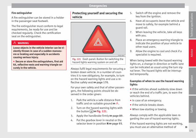
Emergencies
Fire extinguisher
A fire extinguisher can be stored in a holderin the passenger seat footwell.
The fire extinguisher must conform to legalrequirements, be ready for use and bechecked regularly. Check the certificationseal on the extinguisher.
WARNING
Loose objects in the vehicle interior can be vi-olently thrown in case of a sudden manoeu-vre or braking and especially in accidentscausing serious injury.
● Secure or store fire extinguishers, first aidkit, reflective vests and warning triangle se-curely in the vehicle.
Protecting yourself and securing thevehicle
Fig. 121 Dash panel: Button for switching thehazard lights warning system on and off.
Always fulfil legal requirements for securing abroken down vehicle. In a number of coun-tries it is now obligatory, for example, to turnon the hazard warning lights and use a re-flective safety vest ››› page 170.
For your own safety and that of other passen-gers, the following points should be ob-served in the order given:
Park the vehicle a safe distance fromtraffic and on suitable ground ››› .
Turn on the hazard warning lights withthe button ››› Fig. 121.
Apply the handbrake firmly ››› page 89.
Put the gearbox lever in neutral or theselector lever in position N ››› page 93.
1.
2.
3.
4.
Switch off the engine and remove thekey from the ignition.
Have all occupants leave the vehicle andmove to safety, for example behind aguard rail.
When leaving the vehicle, take all keyswith you.
Place an emergency warning triangle toindicate the position of your vehicle toother road users.
Allow the engine to cool and check if aspecialist is required.
When being towed with the hazard warninglights on, a change in direction or traffic lanecan be indicated as usual using the turn sig-nal lever. The hazard lights will be interrup-ted temporarily.
Examples of when to use the hazard warninglights:
● If the vehicles ahead suddenly slow downor reach the end of a traffic jam, to warn thevehicles behind.
● In case of an emergency.
● If the vehicle breaks down.
● When tow-starting or towing.
Always comply with the applicable laws re-garding the use of hazard warning lights.
If the hazard warning lights are not working,you must use an alternative method of »
5.
6.
7.
8.
9.
171
Tech
nica
l spe
cific
atio
nsA
dvic
eO
pera
tion
Saf
ety

Advice
drawing attention to your vehicle. This meth-od must comply with traffic legislation.
WARNING
A faulty vehicle in traffic represents a risk ofaccident for the driver and for other roadusers.
● Stop the vehicle safely as soon as possible.Park the vehicle a safe distance from sur-rounding traffic to lock all the doors in case ofan emergency. Turn on the hazard warninglights to warn other road users.
● Never leave children or disabled peoplealone in the vehicle if the doors are to belocked. In case of an emergency, passengerswill be trapped inside the vehicle. Individualslocked in the vehicle can be exposed to veryhigh or very low temperatures.
WARNING
The components of the exhaust system reachvery high temperatures. This could cause afire and considerable damage.
● Always park your vehicle so that no part ofthe exhaust system can come in contact withflammable materials (such as dried grass orfuel).
Note
● The vehicle battery will discharge and rundown if the hazard warning lights remain onfor too long (even with the ignition turnedoff).
● For some vehicles, the brake lights willblink when braking suddenly at speeds of ap-proximately 80 km/h (50 mph) to alert vehi-cles to the rear. If braking continues, the haz-ard warning lights system will automaticallybe turned on at a speed of less than approxi-mately 10 km/h (6 mph). The brake lights re-main lit. Upon accelerating, the hazard warn-ing lights will be automatically turned off.
Vehicle tool kit*
Introduction
When securing the vehicle in case of a break-down, please note the legal requirements foreach country.
Vehicle tool kit
For vehicles with a factory-fitted spare wheelor temporary spare wheel, in addition to win-ter wheels, the luggage compartment maycontain additional vehicle tools ››› page 172.
WARNING
When the vehicle tool kit, tire mobility setand spare wheel are loose in the interior theycan be violently thrown in case of a suddenmanoeuvre or braking and especially in acci-dents, causing serious injury.
● Ensure that the vehicle tool kit, the tire mo-bility set and the spare wheel or temporary
spare wheel are safely secured in the luggagecompartment.
WARNING
Unsuitable or damaged vehicle tools cancause injury or accidents.
● Never work with inappropriate or damagedtools.
Location
Fig. 122 In the luggage compartment: Raisedcarpet.
The vehicle tool kit, spare wheel, temporaryspare wheel and the tire mobility set are stor-ed in the luggage compartment under thecarpeted floor panel ››› Fig. 122.
● If necessary, remove the boot variable floor››› page 73.
172

Emergencies
● Raise the carpet at the recess (arrow)››› Fig. 122.
Note
After use, return the jack to its initial positionusing the handle in order to securely store itin the vehicle.
Accessing the vehicle tool kit and tyremobility system in vehicles fitted withthe SEAT SOUND 7 speaker system(with subwoofer)*
● Open the boot hatch and lift the shelf.
● If necessary, remove the boot variable floor››› page 76.
● Lift up the carpet from the recess and re-move it from the luggage compartment.
● Disconnect the subwoofer’s speaker cable.
● Completely remove the hand-controlledwheel from the centre of the subwooferspeaker by turning it anti-clockwise.
● Take out the subwoofer, which is on top ofthe tools and tyre mobility system.
● When finished, place the tools and systemback in the same way and place as before toensure the speaker sits properly in its hous-ing.
● Place the subwoofer in the direction of thearrow and with the word “FRONT” facing for-ward.
● Reconnect the speaker cable and firmly ro-tate the securing wheel clockwise so that thesubwoofer is firmly in place.
Components
Fig. 123 Components of the vehicle tool kit
The vehicle tool kit depends on the vehicleequipment. The following is a description fora vehicle with all options.
The individual elements of the vehicle toolkit ››› Fig. 123
Screwdriver with hexagon socket in thehandle for screwing and unscrewing thewheel bolts. The screwdriver bit is inter-
1
changeable. The screwdriver may befound underneath the wheel spanner.
Adapter for anti-theft bolt. SEAT recom-mend you carry the wheel bolt adapter inthe vehicle tool kit at all times. The codenumber of the anti-theft wheel bolt isstamped on the front of the adapter. Incase it is lost, another adapter can be or-dered using this number. Note the anti-theft bolt code for the wheels and keep itin a place other than the vehicle.
Towline anchorage, removable.
Wire hook for pulling off the wheel cover,integral hubcaps and the wheel boltcaps.
Jack. Before storing the jack in the toolkit, fold its hook. The crank must then befolded tight against the side of the jack inorder for it to be safely stored.
Wheel spanner.
Wheel bolt cap clips.
Note
The jack does not generally require any main-tenance. If required, it should be greased us-ing universal type grease.
2
3
4
5
6
7
173
Tech
nica
l spe
cific
atio
nsA
dvic
eO
pera
tion
Saf
ety

Advice
Changing a wheel
Introduction
Some vehicle versions and models do nothave a factory-fitted jack or box spanner. Inthis case, we recommend consulting a Speci-alised workshop to change the wheel.
You should only change the wheels yourself ifthe vehicle is parked in a safe place, you arefamiliar with the procedure and safety stand-ards and you have all the necessary tools!Otherwise, you should seek professional as-sistance.
WARNING
Changing a wheel can be dangerous, espe-cially on the hard shoulder. Please observethe following rules to minimise the risk of in-jury:
● Stop the vehicle safely as soon as possible.Park at a safe distance from surrounding traf-fic to change a wheel.
● When changing a wheel, keep all passen-gers, and particularly children, a safe dis-tance away from the work area.
● Turn on the hazard warning lights to warnother road users.
● Ensure the ground on which you park is flatand solid. If necessary, support the jack on awide solid base.
● If you are changing a wheel yourself, youshould be familiar with the required proce-dure. Otherwise, you should seek professio-nal assistance.
● Only use suitable tools that are not dam-aged when changing a wheel.
● Always stop the engine, apply the hand-brake lever firmly and place the selector leverin position P, or engage a gear for a manualgearbox to reduce the risk of the vehicle mov-ing accidentally.
● Have the tightening torque of the wheelbolts checked as soon as possible with a reli-able torque wrench.
WARNING
If the wheel trims are not appropriate or notfitted correctly, they could cause major acci-dents or damage.
● Incorrectly mounted wheel trims may comeoff while driving and endanger other roadusers.
● Damaged trims must never be mounted onthe wheels.
● Always ensure that the brake ventilationand cooling is not cut off or blocked. This isalso valid if hubcaps are fitted later. If thereis not enough air, you may require signifi-cantly longer braking distances.
CAUTION
Remove and remount wheel trims taking careto avoid damage to the vehicle.
Hubcaps
Fig. 124 Remove the hubcap of the steelwheel trim
In order to access the wheel bolts, first re-move the hubcap.
Removing and fitting the hubcap
● To remove, take the vehicle tool kit wirehook and attach it to the edge of the wheeltrim ››› Fig. 124.
● Remove the trim by pulling it in the direc-tion of the arrow.
● To replace the hubcap, press the hubcapagainst the trim until it clicks into place.
174

Emergencies
The caps protect the wheel bolts and shouldbe remounted after changing the tyre.
Full hubcaps
Fig. 125 Removing the full hubcap
Removing the full hubcap
● Take the wheel brace and the wire hookfrom the vehicle tool kit ››› page 172.
● Hook the wire through one of the grooveson the hubcap.
● Insert the wheel brace onto the wire hook››› Fig. 125 and pull the hub cap in the direc-tion shown by the arrow.
Fitting hubcaps
Press the hubcap against the wheel so thatthe space for the valve fits over the tyre valve.Make sure that the hubcap is correctly fittedall the way around the wheel. If you are using
an anti-theft wheel lock, screw it in the oppo-site position to the valve.
Wheel bolt caps
Fig. 126 Removing the wheel bolt caps
Removal
– Fit the plastic clip (vehicle tools››› page 172) over the cap until it clicks intoplace ››› Fig. 126.
– Remove the cap with the plastic clip.
The caps protect the wheel bolts and shouldbe remounted after changing the tyre.
The anti-theft wheel locking bolt has a spe-cial cap. This only fits on anti-theft lockingbolts and is not for use with standard wheelbolts.
Wheel bolts
Fig. 127 Changing a wheel: Slacken thewheel bolts.
Fig. 128 Changing a wheel: Tyre valve 1 andposition of anti-theft wheel locking bolt 2 .
Only use the tool supplied with the vehicle toloosen the wheel bolts.
Loosen the wheel bolts only about one turnbefore raising the vehicle with the jack. »
175
Tech
nica
l spe
cific
atio
nsA
dvic
eO
pera
tion
Saf
ety

Advice
If the wheel bolt is very tight, you may beable to loosen it by pushing down on the endof the wheel brace carefully with your foot.Hold on to the vehicle for support and takecare not to slip.
Loosening wheel bolts
● Fit the wheel brace as far as it will go overthe wheel bolt ››› Fig. 127.
● Hold the wheel brace at the end and rotatethe bolt approximately one turn anticlockwise››› .
Loosening anti-theft wheel bolts
For wheels with full hubcap, the anti-theftwheel lock must be threaded into position››› Fig. 128 2 before mounting the hubcap.Otherwise it will not be possible to mount theentire hubcap.
● Take the adapter for anti-theft wheel boltsout of the vehicle tool kit.
● Insert the adapter onto the wheel bolt››› Fig. 128. Push it on as far as it will go.
● Fit the wheel brace onto the adapter as faras possible.
● Hold the wheel brace at the end and rotatethe bolt approximately one turn anticlockwise››› .
Important information about wheel bolts
The wheel rims and bolts have been de-signed to be fitted to factory options. If differ-ent rims are fitted, the correct wheel boltswith the right length and correctly shapedbolt heads must be used. This ensures thatwheels are fitted securely and that the brakesystem functions correctly.
In some circumstances, wheel bolts from thesame model vehicle should not be used.
Wheel bolt tightening torque
The prescribed tightening torque for wheelbolts for steel and alloy wheels is 110 Nm.Have the tightening torque of the wheel boltschecked as soon as possible with a reliabletorque wrench.
If wheel bolts are rusty and it is difficult totighten them, the threads should be replacedand cleaned before checking the tighteningtorque.
Never grease or lubricate wheel bolts or thewheel hub threads. Although they have beentightened to the prescribed torque, theycould come loose while driving.
WARNING
If the wheel bolts are not fitted correctly theycould be released while driving leading toloss of vehicle control and serious damage.
● Only use wheel bolts which correspond tothe wheel rims in question.
● Never use different wheel bolts.
● The bolts and threads should be clean, freeof oil and grease and easy to thread.
● To loosen and tighten the wheel bolts, al-ways use the wheel brace supplied with thevehicle.
● Loosen the wheel bolts only about one turnbefore raising the vehicle with the jack.
● Never grease or lubricate wheel bolts or thewheel hub threads. Although they have beentightened to the prescribed torque, theycould come loose while driving.
● Never loosen the bolted joints of wheelrims with bolted ring trims.
● If the wheel bolts are not tightened to thecorrect torque, they may come loose whiledriving, and the bolts and rims may comeout. If the tightening torque is too high, thewheel bolts and threads can be damaged.
176

Emergencies
Raising the vehicle with the jack
Fig. 129 Jack position points
Fig. 130 Jack mounted on the left rear part ofthe vehicle
The jack may be applied only at the jackingpoints shown (marks on chassis) ››› Fig. 129.Always the relevant jacking point for thewheel to be changed ››› .
Raise the vehicle using only the designatedjacking points.
WARNING
If the vehicle is not correctly raised, it couldfall off the jack causing serious injury. Pleaseobserve the following rules to minimise therisk of injury:
● You should only use a jack approved bySEAT for your vehicle. Other jacks, even thoseapproved for other SEAT models, might slipout of place.
● The ground should be firm and flat. If theground is sloped or soft then the vehiclecould slip and fall off the jack. If necessary,support the jack on a wide solid base.
● If the ground is slippery, such as tiles,place a non-slip surface (a floor mat, for in-stance) beneath the jack to avoid slipping.
● Only fit the jack at the prescribed jackingpoints. The claw of the jack should grip thereinforcement nerve on the underbody››› Fig. 130.
● You should never place a body limb such asan arm or leg under a raised vehicle that issolely supported by the jack.
● If you have to work underneath the vehicle,you must use suitable stands additionally tosupport the vehicle, there is a risk of acci-dent!.
● Never raise the vehicle if it is tilting to oneside or the engine is running.
● Never start the engine when the vehicle israised. The vehicle may come loose from thejack due to the engine vibrations.
177
Tech
nica
l spe
cific
atio
nsA
dvic
eO
pera
tion
Saf
ety
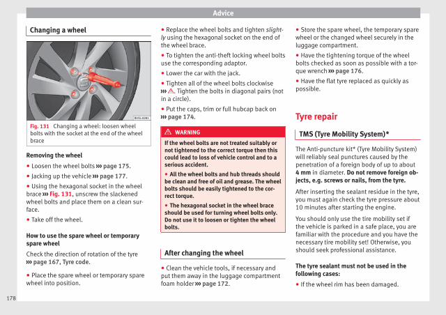
Advice
Changing a wheel
Fig. 131 Changing a wheel: loosen wheelbolts with the socket at the end of the wheelbrace
Removing the wheel
● Loosen the wheel bolts ››› page 175.
● Jacking up the vehicle ››› page 177.
● Using the hexagonal socket in the wheelbrace ››› Fig. 131, unscrew the slackenedwheel bolts and place them on a clean sur-face.
● Take off the wheel.
How to use the spare wheel or temporaryspare wheel
Check the direction of rotation of the tyre››› page 167, Tyre code.
● Place the spare wheel or temporary sparewheel into position.
● Replace the wheel bolts and tighten slight-ly using the hexagonal socket on the end ofthe wheel brace.
● To tighten the anti-theft locking wheel boltsuse the corresponding adaptor.
● Lower the car with the jack.
● Tighten all of the wheel bolts clockwise››› . Tighten the bolts in diagonal pairs (notin a circle).
● Put the caps, trim or full hubcap back on››› page 174.
WARNING
If the wheel bolts are not treated suitably ornot tightened to the correct torque then thiscould lead to loss of vehicle control and to aserious accident.
● All the wheel bolts and hub threads shouldbe clean and free of oil and grease. The wheelbolts should be easily tightened to the cor-rect torque.
● The hexagonal socket in the wheel braceshould be used for turning wheel bolts only.Do not use it to loosen or tighten the wheelbolts.
After changing the wheel
● Clean the vehicle tools, if necessary andput them away in the luggage compartmentfoam holder ››› page 172.
● Store the spare wheel, the temporary sparewheel or the changed wheel securely in theluggage compartment.
● Have the tightening torque of the wheelbolts checked as soon as possible with a tor-que wrench ››› page 176.
● Have the flat tyre replaced as quickly aspossible.
Tyre repair
TMS (Tyre Mobility System)*
The Anti-puncture kit* (Tyre Mobility System)will reliably seal punctures caused by thepenetration of a foreign body of up to about4 mm in diameter. Do not remove foreign ob-jects, e.g. screws or nails, from the tyre.
After inserting the sealant residue in the tyre,you must again check the tyre pressure about10 minutes after starting the engine.
You should only use the tire mobility set ifthe vehicle is parked in a safe place, you arefamiliar with the procedure and you have thenecessary tire mobility set! Otherwise, youshould seek professional assistance.
The tyre sealant must not be used in thefollowing cases:
● If the wheel rim has been damaged.
178

Emergencies
● In outside temperatures below -20 °C(-4 °F).
● In the event of cuts or perforations in thetyre greater than 4 mm.
● If you have been driving with very low pres-sure or a completely flat tyre.
● If the sealant bottle has passed its use bydate.
WARNING
Using the tyre mobility system can be dan-gerous, especially when filling the tyre at theroadside. Please observe the following rulesto minimise the risk of injury:
● Stop the vehicle safely as soon as possible.Park it at a safe distance from surroundingtraffic to fill the tyre.
● Ensure the ground on which you park is flatand solid.
● All passengers and particularly childrenmust keep a safe distance from the work area.
● Turn on the hazard warning lights to warnother road users.
● Use the tyre mobility system only if you arefamiliar with the necessary procedures. Oth-erwise, you should seek professional assis-tance.
● The tyre mobility set is intended for tempo-rary emergency use only until you can reachthe nearest specialised workshop.
● Replace the repaired tyre with the tire mo-bility set as soon as possible.
● The sealant is a health hazard and must becleaned immediately if it comes into contactwith the skin.
● Always keep the tire mobility set out of thereach of small children.
● Never use an equivalent jack, even if it hasbeen approved for your vehicle.
● Always stop the engine, apply the hand-brake lever firmly and engage gear if using amanual gearbox, in order to reduce the risk ofvehicle involuntary movement.
WARNING
A tyre filled with sealant does not have thesame performance properties as a conven-tional tyre.
● Never drive faster than 80 km/h (50 mph).
● Avoid heavy acceleration, hard braking andfast cornering.
● Drive for only 10 minutes at a maximumspeed of 80 km/h (50 mph) and then checkthe tyre.
For the sake of the environment
Dispose of used or expired sealant observingany legal requirements.
Note
● A new bottle of sealant can be purchased atSEAT dealerships.
● Take into account the separate instructionmanual of the tyre mobility set* manufactur-er.
Contents of the tyre mobility system*
Fig. 132 Standard representation: Contentsof the tyre mobility system.
The tyre mobility set is located underneaththe floor covering in the luggage compart-ment. It includes the following components››› Fig. 132:
Tyre valve remover
Sticker indicating maximum speed “max.80 km/h” or “max. 50 mph”
Filler tube with cap
Air compressor »
1
2
3
4
179
Tech
nica
l spe
cific
atio
nsA
dvic
eO
pera
tion
Saf
ety

Advice
Tube for inflating tyres
Warning provided by tyre pressure moni-toring system1)
Air bleed screw2)
ON/OFF switch
12 volt connector
Bottle of sealant
Spare tyre valve
The valve insert remover 1 has a gap at thelower end for a valve insert. The valve insertcan only be screwed or unscrewed in thisway. This also applies to its replacement part11 .
Sealing and inflating a tyre
Sealing a tyre
● Unscrew the tyre valve cap.
● Use the corresponding enclosed extractor››› Fig. 132 1 to unscrew the tyre valve in-sert. Place the valve insert on a clean surface.
● Vigorously shake the sealant bottle››› Fig. 132 10 for several seconds.
● Screw the inflator tube ››› Fig. 132 3 se-curely into the sealant bottle in a clockwise
5
6
7
8
9
10
11
direction. The seal on the mouth of the bottlemoves automatically.
● Remove the lid from the filling tube››› Fig. 132 3 and screw the open end of thetube into the tyre valve.
● Hold the tyre sealant can upside down andfill the complete contents of the can into thetyre.
● Remove the tyre sealant bottle from thevalve.
● Screw the valve insert again with the corre-sponding enclosed extractor ››› Fig. 132 1
into the tyre valve.
Inflating the tyre
● Securely screw the tyre inflator tube››› Fig. 132 5 of the compressor into the tyrevalve.
● Check whether the air bleed screw››› Fig. 132 7 is closed.
● Start the vehicle engine and leave it run-ning.
● Attach the connector ››› Fig. 132 9 to a 12volt socket of the vehicle ››› page 72.
● Connect the air compressor with theON/OFF switch ››› Fig. 132 8 .
● Keep the air compressor running until itreaches 2.0 to 2.5 bar (29-36 psi /200-250 kPa) ››› . Maximum operation time8 minutes ››› .
● Disconnect the air compressor.
● If it is not possible to achieve an air pres-sure of 2.0 to 2.5 bar (29-36 psi /200-250 kPa), unscrew the tyre inflator tubefrom the tyre valve.
● Move the vehicle some 10 metres forwardor backward so that the sealant is evenly dis-tributed in the tyre interior.
● Securely screw the compressor tyre inflatortube into the tyre valve and repeat the infla-tion process.
● If the indicated pressure can still not bereached, the tyre is too badly damaged. Thetyre cannot be sealed with the anti-puncturekit. Do not continue driving. You should ob-tain professional assistance ››› .
● Disconnect the air compressor and unscrewthe flexible inflator tube from the tyre valve.
● When the tyre pressure is between 2.5 and2.0 bars, immediately continue driving with-out exceeding 80 km/h (50 mph).
● After 10 minutes, Check the pressure again››› page 181.
1) It can also be integrated in the compressor.2) In its place, the compressor may have a button.
180

Emergencies
WARNING
When inflating the wheel, the air compressorand the inflator tube may become hot.
● Protect hands and skin from hot parts.
● Do not place the hot flexible inflator tube orhot air compressor on flammable material.
● Allow them to cool before storing the de-vice.
● If it is not possible to inflate the tyre to atleast 2.0 bars (29 psi / 200 kPa), the tyre istoo badly damaged. The sealant is not in agood condition to seal the tyre. Do not con-tinue driving. Seek specialist assistance.
CAUTION
Switch off the air compressor after a maxi-mum of 8 operational minutes to avoid over-heating! Before switching on the air compres-sor again, let it cool for several minutes.
Check after 10 minutes of driving
Screw in the inflator tube ››› Fig. 132 5
again and check the pressure on the gauge6 .
1.3 bar (19 psi / 130 kPa) and lower:
● Stop the vehicle! The tyre cannot be sealedsufficiently with the tyre mobility set.
● You should obtain professional assistance››› .
1.4 bar (20 psi / 140 kPa) and higher:
● Set the tyre pressure to the correct valueagain ››› page 158.
● Carefully resume your journey until youreach the nearest specialised workshop with-out exceeding 80 km/h (50 mph).
● Have the damaged tyre replaced.
WARNING
Driving with an unsealed tyre is dangerousand can cause accidents and serious injury.
● Do not continue driving if the tyre pressureis 1.3 bar (19 psi / 130 kPa) and lower.
● Seek specialist assistance.
Starting assistance
Introduction
If the engine fails to start because of a dis-charged battery, the battery of another vehi-cle can be used to start the engine. Beforestarting, check the magic eye on the battery››› page 154.
For starting assistance, jump lead cables con-forming to the standard DIN 72553 are re-quired (see the cable manufacturer instruc-tions). The cable section in vehicles with pet-rol engine must be at least 25 mm2.
WARNING
Incorrect use of jump leads and incorrectlyjump starting could cause the battery to ex-plode resulting in serious injury. Please ob-serve the following rules to minimise the riskof a battery explosion:
● The battery providing current must havethe same voltage (12V) and approximatelythe same capacity (see markings on battery)as the flat battery.
● Never charge a frozen or recently thawedbattery. A flat battery can also freeze at tem-peratures close to 0 °C (+32 °F).
● If a battery is frozen and/or has been frozenthen it must be replaced.
● A highly explosive mixture of gases is re-leased when the battery is being charged. Al-ways keep lit cigarettes, flames, sparks andfire far from the battery. Never use a mobiletelephone when connecting and removing thejump leads.
● Charge the battery only in well ventilatedareas given that when the battery is chargedby outside assistance, it creates a mix ofhighly explosive gases.
● Jump leads should never enter into contactwith moving parts in the engine compart-ment.
● Never switch the positive and negativepoles or connect the jump leads incorrectly.
● Note the instruction manual provided bythe manufacturer of the jump leads. »
181
Tech
nica
l spe
cific
atio
nsA
dvic
eO
pera
tion
Saf
ety

Advice
CAUTION
To avoid considerable damage to the vehicleelectrical system, note the following careful-ly:
● If the jump leads are incorrectly connected,this could result in a short circuit.
● The vehicles must not touch each other,otherwise electricity could flow as soon asthe positive terminals are connected.
How to jump start: description
Fig. 133 Diagram of connections for vehicleswithout Start-Stop system.
Fig. 134 Diagram of connections for vehicleswith Start-Stop system.
Jump lead terminal connections
1. Switch off the ignition of both vehicles››› .
2. Connect one end of the red jump lead tothe positive + terminal of the vehiclewith the flat battery A ››› Fig. 133.
3. Connect the other end of the red jumplead to the positive terminal + in the ve-hicle providing assistance B .
4. For vehicles without Start-Stop system:connect one end of the black jump lead tothe negative terminal – of the vehicleproviding the current B ››› Fig. 133.
– For vehicles with Start-Stop system: con-nect one end of the black jump lead X to asuitable ground terminal, to a solid piece ofmetal in the engine block, or to the engineblock itself ››› Fig. 134.
5. Connect the other end of the black jumplead X to a solid metal component boltedto the engine block or to the engine blockitself of the vehicle with the flat battery.Do not connect it to a point near the bat-tery A .
6. Position the leads in such a way that theycannot come into contact with any movingparts in the engine compartment.
Starting
7. Start the engine of the vehicle with theboosting battery and let it run at idlingspeed.
8. Start the engine of the vehicle with the flatbattery and wait 2 or 3 minutes until theengine is “running”.
Removing the jump leads
9. Before you remove the jump leads, switchoff the dipped beam headlights (if theyare switched on).
10.Turn on the heater blower and heated rearwindow in the vehicle with the flat battery.This helps minimise voltage peaks whichare generated when the leads are discon-nected.
11.When the engine is running, disconnectthe leads in reverse order to the detailsgiven above.
182

Emergencies
Connect the battery clamps so they havegood metal-to-metal contact with the batteryterminals.
If the engine fails to start, switch off the start-er after about 10 seconds and try again afterabout 1 minute.
WARNING
● Please note the safety warnings referring toworking in the engine compartment››› page 143.
● The battery providing assistance must havethe same voltage as the flat battery (12V) andapproximately the same capacity (see imprinton battery). Failure to comply could result inan explosion.
● Never use jump leads when one of the bat-teries is frozen. Danger of explosion! Even af-ter the battery has thawed, battery acid couldleak and cause chemical burns. If a batteryfreezes, it should be replaced.
● Keep sparks, flames and lighted cigarettesaway from batteries, danger of explosion.Failure to comply could result in an explo-sion.
● Observe the instructions provided by themanufacturer of the jump leads.
● Do not connect the negative cable from theother vehicle directly to the negative terminalof the flat battery. The gas emitted from thebattery could be ignited by sparks. Danger ofexplosion.
● Do not attach the negative cable from theother vehicle to parts of the fuel system or tothe brake line.
● The non-insulated parts of the batteryclamps must not be allowed to touch. Thejump lead attached to the positive batteryterminal must not touch metal parts of the ve-hicle, this can cause a short circuit.
● Position the leads in such a way that theycannot come into contact with any movingparts in the engine compartment.
● Do not lean on the batteries. This could re-sult in chemical burns.
Note
The vehicles must not touch each other, oth-erwise electricity could flow as soon as thepositive terminals are connected.
Towing and tow starting
Introduction
When towing or tow starting, respect the le-gal requirements.
For technical reasons, it is not possible totow a vehicle if the battery is flat.
WARNING
A vehicle with a flat battery should never betowed.
● Never remove the key from the ignitionlock. Otherwise, the steering wheel lockcould suddenly lock. The vehicle would notbe controlled and a serious accident couldensue.
WARNING
When towing the vehicle, the handling andbraking efficiency change considerably.Please observe the following instructions tominimise the risk of serious accidents and in-jury:
● As the driver of the vehicle being towed:
– The brake must be depressed must hard-er as the brake servo does not operate.Always remain aware to avoid collisionwith the towing vehicle.
– More strength is required at the steeringwheel as the power steering does not op-erate when the engine is switched off.
● As the driver of the towing vehicle:
– Accelerate gently and carefully.
– Avoid sudden braking and manoeuvres.
– Brake well in advance than usual andbrake gently. »
183
Tech
nica
l spe
cific
atio
nsA
dvic
eO
pera
tion
Saf
ety

Advice
CAUTION
● Carefully fit and remove the towline anchor-age and its cover to avoid damage to the ve-hicle (e.g. paintwork).
● When towing, fuel could enter the catalyticconverter and cause damage!
Note
Fitting a towline anchorage to the rear bump-er is not possible. The vehicle is not suitablefor towing other vehicles.
Instructions for tow starting
In general, the vehicle should not be startedby towing. Jump-starting is much more pref-erable ››› page 181.
For technical reasons, the following vehiclescan not be tow started:
● Vehicles with an automatic gearbox.
● If the vehicle battery is flat, it is possiblethat the engine control unit does not operatecorrectly.
However, if your vehicle must absolutely betow-started (manual gearbox):
● Put it into second or third gear.
● Keep the clutch pressed down.
● Switch on the ignition and the hazard warn-ing lights.
● Release the clutch when both vehicles aremoving.
● As soon as the engine starts, press theclutch and move the gear lever into neutral.This helps to prevent a collision with the tow-ing vehicle.
CAUTION
When tow-starting, fuel could enter the cata-lytic converter and damage it.
Notes on towing
Tow rope or tow bar
When towing, the tow bar is the safest andvehicle friendly way. You should only use atow rope if you do not have a tow bar.
A tow rope should be slightly elastic to avoiddamage to both vehicles. It is advisable touse a tow rope made of synthetic fibre or sim-ilarly elastic material.
Only secure the tow rope or tow bar to thetowline anchorage or specially designed fit-ting.
Towing vehicles with an automatic gearbox
Note the following for a towed vehicle:
● Make sure the gear selector lever is in the Nposition.
● Do not drive faster than 50 km/h (30 mph)when towing a vehicle.
● Do not tow further than 50 km (30 miles).
● If a breakdown truck is used, the vehiclemust be towed with the front wheels raised.
Situations in which the vehicle should not betowed
In the following cases, the vehicle should notbe towed but transported on a trailer or spe-cial vehicle:
● If the vehicle gearbox does not contain lu-bricant due to a fault.
● If the battery is flat and the steering cannotbe unlocked as a result, the electronic steer-ing lock and electronic parking brake cannotbe disengaged.
● If the vehicle to be towed has an automaticgearbox and the distance to be covered isgreater than 50 km (30 miles).
Note
The vehicle can only be towed if the steeringlock electronic gearbox lock is deactivated. Ifthe vehicle has no power supply or there isan electric system fault, the engine must bestarted using jump leads to deactivate thesteering column electronic gearbox lock.
184

Emergencies
Fitting the front towline anchorage
Fig. 135 On the right-hand side of the frontbumper: Remove the cover.
Fig. 136 On the right-hand side of the frontbumper: Screw in the towline anchorage.
The location for the removable tow ring is onthe right-hand side of the front bumper be-hind a cover ››› Fig. 135.
The towline anchorage should always be keptin the vehicle.
Note the instructions for towing ››› page 184.
Fitting the towline anchorage
● Take the towline anchorage from the vehi-cle tool kit in the luggage compartment››› page 172.
● Press the upper part of the cover ››› Fig. 135(arrow) to disengage and release the cover.
● Remove the cover and leave it hangingfrom the vehicle.
● Screw in the tow ring into its housing anti-clockwise as far as it will go ››› Fig. 136 ››› .Use a suitable tool to firmly tighten the tow-line anchorage in its location.
● After towing, remove the tow ring by turn-ing it clockwise.
● Place the cover's upper tab on the openingof the bumper and carefully guide the lowertab on the edge of the opening. If necessary,press the lower tab from below.
● Press the lower area of the cover until thelower tab engages in the bumper.
CAUTION
The towline anchorage must always be com-pletely and firmly tightened. Otherwise, itcould be released while towing and tow-start-ing.
Towing advice
Towing requires some experience, especiallywhen using a tow rope. Both drivers shouldbe familiar with the technique required fortowing. For this reason, inexperienced driversshould abstain.
While driving, avoid excessive traction forcesand jerking. When towing on an unpavedroad, there is always a risk of overloadingand damaging the anchorage points.
If the vehicle is towed, with the hazard warn-ing lights on and the ignition switched on,the turn signal may be used to indicatechanges of direction. Simply operate the turnsignal lever as usual. Meanwhile, the hazardwarning lights will go off. When the turn sig-nal lever is returned to the rest position, thehazard warning lights will be turned on auto-matically.
Notes for the driver of the towed vehicle
● Keep the ignition running to prevent thesteering wheel from locking and also to allowthe use of the turn signals, horn, windscreenwipers and washers.
● As the power assisted steering does notwork if the engine is not running, you willneed more strength to steer than normally.
● The brake must be depressed must harderas the brake servo does not operate. Avoidhitting the towing vehicle. »
185
Tech
nica
l spe
cific
atio
nsA
dvic
eO
pera
tion
Saf
ety

Advice
● Note the instructions and information con-tained in the Instruction Manual for the vehi-cle to be towed.
Notes for the driver of the towing vehicle
● Accelerate gently and carefully. Avoid sud-den manoeuvres.
● Brake well in advance than usual and brakegently.
● Note the instructions and information con-tained in the Instruction Manual for the vehi-cle to be towed.
Emergency locking andunlocking
Introduction
The doors and rear lid can be locked manual-ly and partially opened, for example if the keyor the central locking is damaged.
WARNING
Opening and closing doors carelessly cancause serious injury.
● If the vehicle is locked from outside, thedoors and windows cannot be opened fromthe inside.
● Never leave children or disabled peoplealone in the car. They could be trapped in the
car in an emergency and will not be able toget themselves to safety.
● Depending on the time of the year, temper-atures inside a locked and closed vehicle canbe extremely high or extremely low resultingin serious injuries and illness or even death,particularly for young children.
WARNING
Getting in the way of the doors and the rearlid is dangerous and can lead to serious in-jury.
● Open and close the doors and the rear lidonly when there is nobody in the way.
CAUTION
When opening and closing in an emergency,carefully disassemble components and thenreassemble them carefully to avoid damageto the vehicle.
Manually locking and unlocking thedriver door
Fig. 137 Driver side door handle with lock cyl-inder
As a general rule, when the driver door islocked all other doors are locked. Unlockingmanually only opens the driver door.
● Unfold the key shaft if necessary››› page 43.
● Insert the key shaft into the lock cylinder tounlock or lock the vehicle ››› Fig. 137.
186

Emergencies
Manually locking the passenger sidedoor
Fig. 138 To the front of the passenger sidedoor: Emergency lock, hidden by a rubbercap.
Fig. 139 Emergency locking of the vehicle us-ing the vehicle key
The passenger door can be manually locked.
● Door open.
● Remove the rubber cap to the front of thedoor. The rubber cap is marked with a locksymbol ››› Fig. 138.
● Unfold the key shaft if necessary››› page 43.
● Insert the key shaft horizontally into theopening and moved the coloured lever for-ward ››› Fig. 139.
● Replace the rubber cap and close the door.
● Check if the door is locked.
● Have the vehicle checked by a specialisedworkshop.
Note
The doors can be opened and unlocked indi-vidually from the inside by pulling the insidedoor handle. If necessary, pull the inner doorrelease lever twice ››› page 45.
Emergency unlocking the rear lid
Fig. 140 From the luggage compartment:Emergency unlocking of the booth hatch.
● If necessary, fold the rear seat bench back-rest forward ››› page 64.
● Remove equipment to access the inside ofthe rear lid.
● Unfold the key shaft ››› page 43.
● Insert the key shaft into the rear lid open-ing ››› Fig. 140 and press the release lever inthe direction of the arrow to unlock the rearlid.
187
Tech
nica
l spe
cific
atio
nsA
dvic
eO
pera
tion
Saf
ety

Advice
Changing the windscreen wiperblades
Changing windscreen wiper blades
Fig. 141 Changing the front wiper blades
Fig. 142 Changing the rear wiper blade
The windscreen wiper blades are supplied asstandard with a layer of graphite. This layer isresponsible for ensuring that the wipe is si-lent. If the graphite layer is damaged, the
noise of the water as it is wiped across thewindscreen will be louder.
Check the condition of the wiper blades regu-larly. If the wipers scrape across the glassthey should be changed if they are damaged,or cleaned if they are dirty ››› .
Damaged wiper blades should be replacedimmediately. These are available from quali-fied workshops.
Lifting and unfolding the wiper arms
The wiper arm may only be lifted at the pointwhere it is fastened to the blade.
For windscreen wipers, please note: the wip-er should be in service position before un-folding it ››› page 60.
Cleaning windscreen wiper blades
● Lifting and unfolding the wiper arms.
● Use a soft cloth to remove dust and dirtfrom the windscreen wiper blades.
● If the blades are very dirty, a sponge ordamp cloth may be used ››› .
Changing the windscreen wiper blades
● Lifting and unfolding the wiper arms.
● Hold down the release button››› Fig. 141 1 while gently pulling the bladein the direction of the arrow.
● Fit a new wiper blade of the same lengthand design on to the wiper arm and hook itinto place.
● Rest the wiper arms back onto the wind-screen.
Changing the rear wiper blade
● Lift the windscreen wiper arm and fold it atan angle of approximately 60° ››› Fig. 142.
● Press and hold the release button 1 .
● Fold the wiper blade towards the wind-screen wiper arm ››› Fig. 142 (arrow A ) whilesimultaneously pulling in the direction of ar-row B . This may require some strength.
● Insert a new blade of the same length andtype in the windscreen wiper arm in the op-posite direction to the arrow B and hook in-to place. This feature is operational when theknob is in position (arrow A ).
● Return the windscreen wiper arm to thewindscreen. Do not let it simply drop down!
WARNING
Worn or dirty wiper blades reduce visibilityand increase the risk of accident and seriousinjury.
● Always replace damaged or worn blades orblades which do not clean the windscreencorrectly.
188

Fuses and bulbs
CAUTION
● Damaged or dirty windscreen wipers couldscratch the glass.
● If products containing solvents, roughsponges or sharp objects are used to cleanthe blades, the graphite layer will be dam-aged.
● Never use fuel, nail varnish remover, paintthinner or similar products to clean the win-dows.
Note
If wax deposits, other cleaning products fromthe automatic car wash, or other care prod-ucts, are left on the windscreen and the rearwindow, the blades can scratch the glass. Re-move wax deposits with a special product orcleaning cloths.
Fuses and bulbs
Fuses
Introduction
Due to the constant updating of vehicles,fuse assignments based on equipment andthe use of the same fuse for various electricalcomponents, it is not possible to provide anup-to-date summary of the fuse positions forthe electrical components at the time ofprinting this manual. For detailed informationabout the fuse positions, please consult atechnical service.
In general, a fuse can be assigned to variouselectrical components. Likewise, an electricalcomponent can be protected by severalfuses.
Only replace fuses when the cause of theproblem has been solved. If a newly insertedfuse blows after a short time, you must havethe electrical system checked by a special-ised workshop as soon as possible.
WARNING
The high voltages in the electrical system cangive serious electrical shocks, causing burnsand even death!
● Never touch the electrical wiring of the igni-tion system.
● Take care not to cause short circuits in theelectrical system.
WARNING
Using unsuitable fuses, repairing fuses orbridging a current circuit without fuses cancause a fire and serious injury.
● Never use a fuse with a higher value. Onlyreplace fuses with a fuse of the same amper-age (same colour and markings) and size.
● Never repair a fuse.
● Never replace a fuse by a metal strip, stapleor similar.
CAUTION
● To prevent damage to the vehicle's electricsystem, before replacing a fuse always turnoff the ignition, the lights and all electricalelements and remove the key from the igni-tion.
● If you replace a fuse with higher-ratingfuse, you could cause damage to another partof the electrical system.
● Protect the fuse boxes when open to pre-vent the entry of dust or humidity as they candamage the electrical system.
Note
One component may have more than onefuse. »
189
Tech
nica
l spe
cific
atio
nsA
dvic
eO
pera
tion
Saf
ety

Advice
Note
Several components may run on a singlefuse.
Vehicle fuses
Fig. 143 Below the driver side dash panel:fuse box cover
Fig. 144 In the engine compartment: fuse boxcover
Only replace fuses with a fuse of the sameamperage (same colour and markings) andsize.
Identifying fuses situated below the driver-side dash panel by colours
Colour Amp rating
Purple 3
Light brown 5
Brown 7.5
Red 10
Blue 15
Yellow 20
White or trans-parent
25
Green 30
Orange 40
Opening and closing the fuse box situatedbelow the dash panel
● Opening: Press the unlock button››› Fig. 143 1 until it is possible to open thecover. Fold the cover down.
● Closing: Fold the cover up in the oppositedirection to the arrow until it clicks into thelocking lever 1 .
To open the engine compartment fuse box
● Open the bonnet ››› page 143.
● Press the attachment tabs in the directionindicated by the arrow (thin arrows) to re-lease the fuse box cover ››› Fig. 144.
● Then lift the cover out.
● To fit the cover, place it on the fuse box.Push the attachment tabs down, in the oppo-site direction indicated by the arrow untilthey click audibly into place.
CAUTION
● Always carefully remove the fuse box cov-ers and refit them correctly to avoid problemswith your vehicle.
● Protect the fuse boxes when open to avoidthe entry of dust or humidity. Dirt and humid-ity inside fuse boxes can cause damage tothe electrical system.
Note
In the vehicle, there are more fuses thanthose indicated in this chapter. These shouldonly be changed by a specialised workshop.
190

Fuses and bulbs
Replacing a blown fuse
Fig. 145 Image of a blown fuse
Preparation
● Switch off the ignition, lights and all elec-trical equipment.
● Open the corresponding fuse box››› page 190.
Identifying a blown fuse
A fuse is blown if its metal strip is ruptured››› Fig. 145.
Point a lamp at the fuse. This will make iteasier to see if the fuse is blown.
To replace a fuse
● Remove the fuse.
● Replace the blown fuse by one with anidentical amperage rating (same colour andmarkings) and identical size ››› .
● Replace the cover again or close the fusebox lid.
CAUTION
If you replace a fuse with higher-rating fuse,you could cause damage to another part ofthe electrical system.
Changing bulbs
Introduction
Changing bulbs requires a certain amount ofmanual skill. If you are unsure, SEAT recom-mends that you consult a technical service orrequest assistance from a specialist. In gen-eral a specialist is needed if, in addition tothe bulbs, other vehicle components requireremoval.
You should store spare light bulbs in the ve-hicle for safety-relevant lights. Spare bulbsmay be obtained from the technical services.In some countries, it is a legal requirement tocarry spare bulbs in the vehicle.
Driving with faults and blown bulbs on thevehicle exterior lighting is against the law.
Additional bulb specifications
The specifications of some headlamp bulbsand bulbs for the tail lamps fitted at the fac-tory may be different to those of conventional
bulbs. Bulb information is displayed on thebulb socket or on the bulb itself.
WARNING
If the road is not well-lit and the vehicle isnot clearly visible to other drivers, there is arisk of accident.
WARNING
Failure to replace bulbs correctly may causeserious accidents.
● Before carrying out any work in the enginecompartment please read and observe thewarnings ››› page 143. In any vehicle, the en-gine compartment is a hazardous area andcould cause severe injury.
● The bulbs H4, HB4 and H7 are pressurisedand might explode on changing them.
● Only replace the bulbs concerned whenthey have cooled.
● Never replace bulbs alone if you are not fa-miliar with the operations necessary. If youare not sure about procedures then visit aspecialised workshop to carry out the neces-sary work.
● Never touch the bulb glass directly. Finger-prints will be evaporated by the heat of theoperating bulb thus “fogging” up the reflec-tor.
● The headlamp frameworks in the enginecompartment and the tail lamps containsharp elements. Always protect your handswhen changing bulbs. »
191
Tech
nica
l spe
cific
atio
nsA
dvic
eO
pera
tion
Saf
ety

Advice
CAUTION
● After changing a bulb, if the rubber coversare not replaced correctly on the headlampframework, the electrical installation may be
damaged, especially if water is allowed to en-ter.
● Remove the ignition key before working onthe electric system. Otherwise, a short circuitcould occur.
● Switch off the lights and the parking lightbefore changing a bulb.
● Take good care to avoid damaging any com-ponents.
Replacing the bulbs in the headlights
Fig. 146 In the engine compartment: Rear view ofthe front left headlight with rubber cover: A dip-ped beam and main beam headlights, B sidelights and daytime driving lights and C turn sig-nal
There is no need to remove the headlight toreplace bulbs.
Complete operations only in the sequence given:
Fig. 146A B C
Dipped beam and main beam headlights Side light and daytime driving light Turn signals (front)
1. Open the bonnet ››› page 143.
2.
Remove the bulb connector H4. Remove the rubber cover usingthe tabs. Turn the bulb holder in an anticlockwise direction as far as it will go and remove it, along with
the bulb, pulling backwards.Press the retaining clip D downwards in the direction of the ar-row, and unclip sideways and remove it.
192
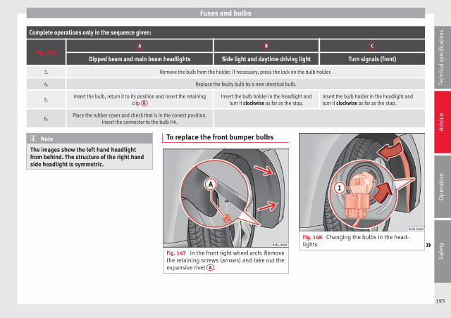
Fuses and bulbs
Complete operations only in the sequence given:
Fig. 146A B C
Dipped beam and main beam headlights Side light and daytime driving light Turn signals (front)
3. Remove the bulb from the holder. If necessary, press the lock on the bulb holder.
4. Replace the faulty bulb by a new identical bulb.
5.Insert the bulb, return it to its position and insert the retaining
clip DInsert the bulb holder in the headlight and
turn it clockwise as far as the stop.Insert the bulb holder in the headlight andturn it clockwise as far as the stop.
6.Place the rubber cover and check that is in the correct position.
Insert the connector to the bulb H4.
Note
The images show the left hand headlightfrom behind. The structure of the right handside headlight is symmetric.
To replace the front bumper bulbs
Fig. 147 In the front right wheel arch: Removethe retaining screws (arrows) and take out theexpansive rivet A .
Fig. 148 Changing the bulbs in the head-lights »
193
Tech
nica
l spe
cific
atio
nsA
dvic
eO
pera
tion
Saf
ety

Advice
Complete operations only in the sequence giv-en:
1.Unscrew the 2 retaining screws of the wheel archtrim ››› Fig. 147 (arrows) with the screwdriver fromthe vehicle took kit ››› page 172.
2.
Unscrew the expansive rivet in the lower front partof the wheel arch trim A with the screwdriverfrom the vehicle tool kit and completely remove it››› page 172.
3. Carefully fold the wheel arch trim to the side.
4.Release the connector ››› Fig. 148 1 and removeit.
5.
Turn the bulb holder ››› Fig. 148 in the direction ofthe arrow, in an anticlockwise direction as far as itwill go and remove it, along with the bulb, pullingbackwards.
6. Replace the faulty bulb by a new identical bulb.
7.Insert the bulb holder in the headlight and turn itclockwise as far as the stop.
8.Plug the connector 1 into the bulb holder. Theconnector must audibly click into place.
9. Replace the wheel arch trim into its position.
10.Place the expansive rivet in the wheel arch trimand bumper and press it completely inwards››› Fig. 147 A .
11.Securely screw the 2 retaining screws ››› Fig. 147(arrows) with a screwdriver.
Changing the bulbs in the rear lights
Fig. 149 On the side of the luggage compart-ment: A: Remove the cover, B: Removing thetail light units
Fig. 150 Tail light unit: C: Remove the bulbholder, D: Remove the bulbs.
Complete operations only in the sequencegiven.
Removing the tail light units
1. Open the rear lid ››› page 50.
2.Carefully remove the cover 1 towards the lever››› Fig. 149 A.
3.Pull the release 3 in the connector 2 in the di-rection of the arrow ››› Fig. 149 B. Use the screw-driver in the vehicle tool kit.
4.Press position 4 and remove the connector 2
››› Fig. 149 B.
194

Fuses and bulbs
5. Unscrew the wing nut 5 ››› Fig. 149 B.
6.Remove the tail light from the bodywork by careful-ly pulling backwards.
7.Disassemble the tail light unit and place it on aflat, clean surface.
To change the bulb
8.Unlock the bulb holder locking tab (arrow)››› Fig. 150 C and remove the bulb holder from thetail light.
9.Replace the faulty bulb by a new identical bulb››› Fig. 150 D.
10.Place the lamp holder in the tail light unit. The at-tachment tabs (arrow) should audibly click intoplace ››› Fig. 150 C.
Assembling the tail light units
11.Carefully insert the tail light unit into the openingin the bodywork.
12.Support the tail light with one hand in the assem-bly position and securely screw the wing nut withthe other 5 ››› Fig. 149 B.
13.Ensure that the tail light unit has been correctlyfitted and is firmly secured.
14.Insert the connector 2 into the bulb holder andpress the lock 3 on the connector in the oppo-site direction to the arrow ››› Fig. 149 B.
15. Insert the cover. The cover should lock into place.
16. Close the rear lid ››› page 50.
Changing the number plate light
Fig. 151 On the rear bumper: Remove thenumber plate light.
Fig. 152 Number plate light: Remove the bulbholder.
Complete operations only in the sequence giv-en:
1.With one hand, press on the number plate lightfrom left to right and remove it from the bumper››› Fig. 151.
Complete operations only in the sequence giv-en:
2.Detach the number plate light carefully from thebumper.
3.Turn the bulb holder with the bulb anticlockwiseand remove it in the direction of the arrow››› Fig. 152.
4. Replace the faulty bulb by a new identical bulb.
5.Place the bulb holder in the number plate light andpress in the opposite direction to the arrow as faras possible ››› Fig. 152.
6.
Insert the number plate light carefully into the leftedge of the opening on the bumper. During thisprocess, check that the assembly direction of thenumber plate light is correct, i.e. the spring mustbe on the right.
7.Insert the number plate light into the bumper untilit audibly clicks into place.
195
Tech
nica
l spe
cific
atio
nsA
dvic
eO
pera
tion
Saf
ety

Advice
Changing the side turn signal bulb
Fig. 153 Removing the side turn signal
Fig. 154 Side turn signal: Changing thebulbs.
Complete operations only in the sequence giv-en:
1.With one hand move the side turn signal back-wards ››› Fig. 153 1 .
Complete operations only in the sequence giv-en:
2.Remove the side turn signal from the chassis byleverage 2 .
3.Remove the bulb holder with the bulb in the direc-tion of the arrow ››› Fig. 154 1 .
4.Remove the bulb holder bulb in a straight direc-tion.
5. Replace the faulty bulb by a new identical bulb.
6. Install the lamp holder.
7.
Place the side turn signal on the chassis on theside situated towards the rear of the vehicle untilthe spring clicks into the other side of the side turnsignal.
196

Technical features
Technical specifications
Technical features
Important information
Introduction
The information in the vehicle documentationalways takes precedence over the informa-tion in this Instruction Manual.
All technical specifications provided in thisdocumentation are valid for the standardmodel in Spain. The vehicle data card inclu-ded in the Maintenance Programme or thevehicle registration documents shows whichengine is installed in the vehicle.
The figures may be different dependingwhether additional equipment is fitted, fordifferent models, for special vehicles and forother countries.
Abbreviations used in the TechnicalSpecifications section
Abbrevi-ation
Meaning
kW Kilowatt, engine power measurement.
PSPferdestärke (horsepower), formerly usedto denote engine power.
rpm Revolutions per minute - engine speed.
Nm Newton metres, unit of engine torque.
litres per100 km
Fuel consumption in litres per 100 km (70miles).
g/kmCarbon dioxide emissions in grams per km(mile) travelled.
CO2 Carbon dioxide
CNCetane number, indication of the dieselcombustion power.
RONResearch octane number, indication of theknock resistance of petrol.
Vehicle identification data
Fig. 155 Vehicle data label.
Fig. 156 Vehicle identification number.
Vehicle identification number
The vehicle identification number (chassisnumber) can be read from outside the vehiclethrough a viewer in the windscreen››› Fig. 156. This viewer is located in the lower »
197
Tech
nica
l spe
cific
atio
nsA
dvic
eO
pera
tion
Saf
ety

Technical specifications
part of the windscreen. The vehicle identifica-tion number (chassis number) is also stam-ped on the right water drain channel. The wa-ter drain channel is located between the sus-pension tower and the wing. Open the bon-net to read the vehicle identification number.
Vehicle data plate
The vehicle data label ››› Fig. 155 is at thefront of the spare wheel well. It contains thefollowing data:
Vehicle identification number (chassisnumber).
Vehicle type, engine power, gearbox type.
Engine and gearbox code, paint number,interior equipment.
Optional extras, PR numbers.
These data are also provided in the Mainte-nance Programme.
Specific vehicle weight information
The instructions in the official vehicle docu-ments take precedence. All the technical dataprovided in this documentation is applicableto the basic model. The vehicle data label inthe Maintenance Programme or the vehicledocumentation shows which engine is instal-led in your vehicle.
1
2
3
4
The figures may be different dependingwhether additional equipment is fitted, fordifferent models and for special vehicles.
Kerb weight values shown in the following ta-ble apply to a vehicle with driver (75 kg), liq-uids including a fuel tank 90% full, in addi-tion to tools and a spare wheel ››› . Thekerb weight indicated increases with optionalequipment and retrofitting of accessories,while proportionally reducing carrying ca-pacity.
The load is equivalent to the followingweights:
● Passengers.
● Total equipment.
● Roof load, included in the carrier.
WARNING
Exceeding the maximum authorised weightand the load on the axles could cause dam-age to the vehicle, accidents and serious in-juries.
● The real load on the axles should never ex-ceed the maximum permitted.
● The load and its distribution in the vehiclehave effects on the vehicle handling and thebraking ability. Always drive at a suitablespeed.
CAUTION
Distribute the load as uniformly and as lowdown on the vehicle as possible. When trans-porting heavy objects in the luggage com-partment, these should be placed as far for-ward as possible or over the rear axle to haveas little influence on handling as possible.
Information on fuel consumption
The consumption and emission values indi-cated do not refer to one specific vehicle.They are only to be used to compare the val-ues of the different vehicle versions. The fuelconsumption and CO2 emissions of a vehiclenot only depend on the effective use of fuel.They also depend on your driving style andother non-technical factors.
Calculation of fuel consumption
Fuel consumption and emission values aredetermined according to the current versionof the 715/2007/EC or 80/1268/EEC regula-tion and are valid for the vehicle kerb weight.The specifications do not refer to an individu-al vehicle. To measure the fuel consumption,two measuring cycles are carried out on arolling road test bed. The test criteria are asfollows:
198

Technical features
Urbancycle
Measurement of the urban cycle starts withan engine cold start. City driving is then si-mulated at between 0 and 50 km/h (0 and31 mph).
Roadcycle
In the road cycle simulation, the car under-goes frequent acceleration and braking in allgears, as in normal everyday driving. Theroad speed ranges from 0 to 120 km/h (0and 75 mph).
Com-bined
The average combined consumption is calcu-lated with a weighting of around 37 % for theurban cycle and 63 % for the road cycle.
CO2emis-sions ofthecombi-nation
The exhaust gases are collected during bothdriving cycles to calculate carbon dioxideemissions (urban and road). The gas compo-sition is analysed below to evaluate the CO2
content and other emissions.
Note
● The kerb weight may vary according to thevehicle equipment. This could raise consump-tion and the CO2 emissions slightly.
● In practice, consumption values could bedifferent to the values calculated based onthe 715/2007/EC or 80/1268/EEC regula-tions.
Wheels
Tyre pressure, snow chains, wheelbolts
Tyre pressures
The sticker with the tyre pressure values canbe found on the inside of the fuel tank flap.The tyre pressure values given there are forcold tyres. The slightly raised pressures ofwarm tyres must not be reduced. ›››
Snow chains
Snow chains may be fitted only to the frontwheels.
Consult the section “wheels” of this manual.
Wheel bolts
After the wheels have been changed, thetightening torque of the wheel bolts shouldbe checked as soon as possible with a torquewrench ››› . The tightening torque for steeland alloy wheels is 140 Nm.
WARNING
● Check the tyre pressure at least once permonth. Checking the tyre pressure is very im-portant. If the tyre pressure is too high or toolow, there is an increased danger of accidents- particularly at high speeds.
● If the tightening torque of the wheel boltsis too low, they could loosen while the vehi-cle is in motion. Risk of accident! If the tight-ening torque is too high, the wheel bolts andthreads can be damaged.
Note
We recommend that you ask your TechnicalService for information about appropriatewheel, tyre and snow chain size.
199
Tech
nica
l spe
cific
atio
nsA
dvic
eO
pera
tion
Saf
ety

Technical specifications
Engine specifications
Petrol engine 1.0 44 kW (60 PS)
Engine specifications
Power output in kW (PS) at rpm Maximum torque (Nm at rpm) No. of cylinders/displacement (cm3) Fuel
44 (60)/5,000-6,000 95/3,000-4,300 3/999 Super 95 RONa)
a) Research Octane Number = Anti-detonation rating of the petrol.
Performance Manual Ecomotive Automatic
Top speed (km/h) 160 161 160
Acceleration from 0-80 km/h (seconds) 9.1 9.1 9.4
Acceleration from 0-100 km/h (seconds) 14.4 14.4 15.3
Consumption (l/100 km)/ CO2 (g/km)
Urban cycle 5.6/130 5/116 5.3/123
Extra-urban cycle 3.9/91 3.6/84 3.9/91
Combined 4.5/105 4.1/95 4.4/103
Weights (in kg)
Gross vehicle weight 1,290 1,290 1,290
Weight in running order (with driver) 929 940 932
Gross front axle weight 680 680 680
Gross rear axle weight 640 640 640
Permitted roof load 50 50 50
200

Technical features
Petrol engine 1.0 55 kW (75 PS)
Engine specifications
Power output in kW (PS) at rpm Maximum torque (Nm at rpm) No. of cylinders/displacement (cm3) Fuel
55 (75)/6,200 95/3,000-4,300 3/999 Super 95 RONa)
a) Research Octane Number = Anti-detonation rating of the petrol.
Performance Manual Start-Stop Automatic
Top speed (km/h) 171 172 171
Acceleration from 0-80 km/h (seconds) 8.3 8.3 9.2
Acceleration from 0-100 km/h (seconds) 13.2 13.2 13.9
Consumption (l/100 km)/ CO2 (g/km)
Urban cycle 5.9/137 5.1/118 5.5/127
Extra-urban cycle 4/93 3.7/86 4/94
Combined 4.7/108 4.2/98 4.5/105
Weights (in kg)
Gross vehicle weight 1,290 1,290 1,290
Weight in running order (with driver) 929 940 932
Gross front axle weight 680 680 680
Gross rear axle weight 640 640 640
Permitted roof load 50 50 50
201
Tech
nica
l spe
cific
atio
nsA
dvic
eO
pera
tion
Saf
ety

Technical specifications
Petrol/CNG engine 1.0 50 kW (68 PS)
Engine specifications
Power output in kW (PS) at rpm Maximum torque (Nm at rpm) No. of cylinders/capacity (cm3) Fuel
50 (68)/6,200 90/3,000 3/999 CNG / Super 95 RONa)
a) Research Octane Number = Anti-detonation rating of the petrol.
Performance Petrol CNG
Top speed (km/h) 164
Acceleration from 0-80 km/h (seconds) 10.3
Acceleration from 0-100 km/h (seconds) 16.3
Consumption (l/100 km)/ CO2 (g/km)
Urban cycle 5.5/99 3.6/99
Extra-urban cycle 3.8/68 2.5/68
Combined 4.4/79 2.9/79
Weights (in kg)
Gross vehicle weight 1,370
Weight in running order (with driver) 1,031
Gross front axle weight 680
Gross rear axle weight 640
Permitted roof load 50
202

Technical features
Dimensions
Longitude 3,557 mm
Width 1,641-1,645 mm
Height, unladen 1,478-1,489 mm
Wheelbase 2,420 mm
Turning circle diametera) approx. 9.8 m
Front track widtha) 1,412-1,428 mm
Rear track widtha) 1,408-1,424 mm
Ground clearance withmaximum authorised load
109 mm
a) Depending on the dimensions of the wheel trims and tyres,there may be variations.
CAUTION
● Special care should be taken when parkingin areas with high kerbs or fixed barriers. Ob-jects protruding from the ground may dam-age the bumper or other parts of the vehicleduring manoeuvres.
● Special attention is required when drivingthrough entrances, over ramps, kerbs or oth-er objects. The vehicle underbody, bumpers,mudguards and running gear, and the engineand exhaust system could be damaged asyou drive over these objects.
Capacities
Fuel tank capacity
Petrol enginesAround 35.0 l
, of which approximately 4.0 are thereserve.
Natural gas en-gine
Natural gas: approx. 11 kg; of whichmax. 1.5 kg reserve
Petrol: approx. 10 l; of which approx.5 l reserve
203
Tech
nica
l spe
cific
atio
nsA
dvic
eO
pera
tion
Saf
ety


Index
Index
AAbroad
Extended stay abroad with your vehicle . . . . . 135Sale of vehicle . . . . . . . . . . . . . . . . . . . . . . . . . 135
ABSSee "Brake assist systems" . . . . . . . . . . . . . . . 104
Accessories . . . . . . . . . . . . . . . . . . . . . . . . . . . . . . 118Additional equipment . . . . . . . . . . . . . . . . . . . . . 119Adjust
Headlight range . . . . . . . . . . . . . . . . . . . . . . . . . 58Adjustment
Correct sitting position . . . . . . . . . . . . . . . . . . . . . 6Front seat . . . . . . . . . . . . . . . . . . . . . . . . . . . . . . 63rear head restraints . . . . . . . . . . . . . . . . . . . . . . . 9Steering wheel . . . . . . . . . . . . . . . . . . . . . . . . . . . 7
Aerial . . . . . . . . . . . . . . . . . . . . . . . . . . . . . . . . . . . 135Airbags
description . . . . . . . . . . . . . . . . . . . . . . . . . . . . . 19Airbag system . . . . . . . . . . . . . . . . . . . . . . . . . . 17, 21
activation . . . . . . . . . . . . . . . . . . . . . . . . . . . . . . 20Cleaning dash panel . . . . . . . . . . . . . . . . . . . . 133Control lamp . . . . . . . . . . . . . . . . . . . . . . . . . . . . 23Deactivating the front passenger front airbag . 24Deactivating using the key switch . . . . . . . . . . . 24Differences between front passenger front air-
bag systems . . . . . . . . . . . . . . . . . . . . . . . . . . 22Faults . . . . . . . . . . . . . . . . . . . . . . . . . . . . . . . . . 120Front airbags . . . . . . . . . . . . . . . . . . . . . . . . . . . . 21functioning . . . . . . . . . . . . . . . . . . . . . . . . . . . . . 20Locking the vehicle after airbag deployment . . 46Repairs . . . . . . . . . . . . . . . . . . . . . . . . . . . . . . . 120Side airbags . . . . . . . . . . . . . . . . . . . . . . . . . . . . 22Use of child seats . . . . . . . . . . . . . . . . . . . . . . . . 24Vehicle care . . . . . . . . . . . . . . . . . . . . . . . . . . . . 133
Air conditionerAir recirculation . . . . . . . . . . . . . . . . . . . . . . . . . 84Air vents . . . . . . . . . . . . . . . . . . . . . . . . . . . . . . . 83Faults . . . . . . . . . . . . . . . . . . . . . . . . . . . . . . . . . . 83set . . . . . . . . . . . . . . . . . . . . . . . . . . . . . . . . . . . . 82Things to note . . . . . . . . . . . . . . . . . . . . . . . . . . . 83User instructions . . . . . . . . . . . . . . . . . . . . . . . . 82
Air conditioning system . . . . . . . . . . . . . . . . . . . . . 80Controls . . . . . . . . . . . . . . . . . . . . . . . . . . . . . . . . 81
Air recirculation . . . . . . . . . . . . . . . . . . . . . . . . . . . 84How it works . . . . . . . . . . . . . . . . . . . . . . . . . . . . 84switch off . . . . . . . . . . . . . . . . . . . . . . . . . . . . . . . 84temporarily switch off . . . . . . . . . . . . . . . . . . . . . 84
Air vents . . . . . . . . . . . . . . . . . . . . . . . . . . . . . . . . . 83Alternator . . . . . . . . . . . . . . . . . . . . . . . . . . . . . . . 155Aluminium care . . . . . . . . . . . . . . . . . . . . . . . . . . 129Anodized surfaces . . . . . . . . . . . . . . . . . . . . . . . . 129Anti-lock brake system (ABS) . . . . . . . . . . . . . . . 104Anti-theft bolts . . . . . . . . . . . . . . . . . . . . . . . . . . . 173Anti-theft locking bolts . . . . . . . . . . . . . . . . . . . . 174Anti-theft wheel locking bolts . . . . . . . . . . . . . . . 175Antifreeze . . . . . . . . . . . . . . . . . . . . . . . . . . . . . . . 150Ashtray . . . . . . . . . . . . . . . . . . . . . . . . . . . . . . . . . . 71Aspects to take into account before starting the
vehicle . . . . . . . . . . . . . . . . . . . . . . . . . . . . . . . . . . 5ASR
see Brake assist systems . . . . . . . . . . . . . . . . . 104Assistance systems
Brake assist system (BAS) . . . . . . . . . . . . . . . . 104Cruise control system (CCS) . . . . . . . . . . . . . . . 107Electronic differential lock system (EDL) . . . . . 104Electronic stability control (ESC) . . . . . . . . . . . 103Optical parking system (OPS) . . . . . . . . . . . . . 107Parking aid . . . . . . . . . . . . . . . . . . . . . . . . . . . . 106Parking distance warning system . . . . . . . . . . 106Safety Assist (City Safety Assist function) . . . . 110Start-Stop . . . . . . . . . . . . . . . . . . . . . . . . . . . . . 115
Traction control system (ASR) . . . . . . . . . . . . . 104Traction Control (TC) . . . . . . . . . . . . . . . . . . . . . 104
Assist systemsAnti-lock brake system (ABS) . . . . . . . . . . . . . . 104
Audible warningsControl and warning lamps . . . . . . . . . . . . . . . . 39Lights . . . . . . . . . . . . . . . . . . . . . . . . . . . . . . . . . 56Seat belt not fastened . . . . . . . . . . . . . . . . . . . . 12Speed . . . . . . . . . . . . . . . . . . . . . . . . . . . . . . . . . 42
Automatic belt retainer . . . . . . . . . . . . . . . . . . . . . 16Automatic car wash . . . . . . . . . . . . . . . . . . . . . . . 126Automatic device disconnection . . . . . . . . . . . . . 157automatic gearbox . . . . . . . . . . . . . . . . . . . . . . . . . 93Automatic gearbox . . . . . . . . . . . . . . . . . . . . . . . . . 95
driving . . . . . . . . . . . . . . . . . . . . . . . . . . . . . . . . . 96Ignition key removal lock . . . . . . . . . . . . . . . . . . 87Kickdown . . . . . . . . . . . . . . . . . . . . . . . . . . . . . . . 96malfunction . . . . . . . . . . . . . . . . . . . . . . . . . . . . . 97starting on a slope . . . . . . . . . . . . . . . . . . . . . . . 97stopping on a slope . . . . . . . . . . . . . . . . . . . . . . 97
Axle loads . . . . . . . . . . . . . . . . . . . . . . . . . . . . . . . 198
BBAS
see Brake assist systems . . . . . . . . . . . . . . . . . 104Battery
Change in the vehicle key . . . . . . . . . . . . . . . . . 44Discharging . . . . . . . . . . . . . . . . . . . . . . . . . . . . 172drains . . . . . . . . . . . . . . . . . . . . . . . . . . . . . . . . . 45See Vehicle battery . . . . . . . . . . . . . . . . . . . . . . 154
Battery acid . . . . . . . . . . . . . . . . . . . . . . . . . . . . . . 156Before starting the vehicle . . . . . . . . . . . . . . . . . . . 5Belt tensioner . . . . . . . . . . . . . . . . . . . . . . . . . . . . . 16
Disposal . . . . . . . . . . . . . . . . . . . . . . . . . . . . . . . 17Service and disposal . . . . . . . . . . . . . . . . . . . . . 17
Belt tension limiter . . . . . . . . . . . . . . . . . . . . . . . . . 16Bench . . . . . . . . . . . . . . . . . . . . . . . . . . . . . . . . . . . 74
205

Index
BonnetClosing . . . . . . . . . . . . . . . . . . . . . . . . . . . . . . . 145Opening . . . . . . . . . . . . . . . . . . . . . . . . . . . . . . 145
Boot variable floorextend below . . . . . . . . . . . . . . . . . . . . . . . . . . . 76extend forwards . . . . . . . . . . . . . . . . . . . . . . . . . 76
BrakeBrake servo . . . . . . . . . . . . . . . . . . . . . . . . . . . . . 92
Brake assist systems . . . . . . . . . . . . . . . . . . . . . . 103Brake assist system (BAS) . . . . . . . . . . . . . . . . . . 104Brake fluid . . . . . . . . . . . . . . . . . . . . . . . . . . . . . . 152
Specification . . . . . . . . . . . . . . . . . . . . . . . . . . . 153Brakes . . . . . . . . . . . . . . . . . . . . . . . . . . . . . . . . . . . 89
Brake assist systems . . . . . . . . . . . . . . . . . . . . 103Brake fluid . . . . . . . . . . . . . . . . . . . . . . . . . . . . . 152Brake fluid level . . . . . . . . . . . . . . . . . . . . . . . . 153Brake pads . . . . . . . . . . . . . . . . . . . . . . . . . . . . . 91Changing the brake fluid . . . . . . . . . . . . . . . . . 153Control lamp . . . . . . . . . . . . . . . . . . . . . . . . . . . . 89Emergency brake indicator in case of sudden
braking . . . . . . . . . . . . . . . . . . . . . . . . . . . . . 172Handbrake . . . . . . . . . . . . . . . . . . . . . . . . . . . . . 90Running-in brake pads . . . . . . . . . . . . . . . . . . . . 91Warning lamp . . . . . . . . . . . . . . . . . . . . . . . . . . . 89
Brake servo . . . . . . . . . . . . . . . . . . . . . . . . . . 92, 103Brake system
Malfunction . . . . . . . . . . . . . . . . . . . . . . . . . . . . . 92Brake systems . . . . . . . . . . . . . . . . . . . . . . . . . . . 103Breakdown
Securing the vehicle . . . . . . . . . . . . . . . . . . . . . 171Bulb fault
See changing bulbs . . . . . . . . . . . . . . . . . . . . . 191
CCapacities
Fuel tank . . . . . . . . . . . . . . . . . . . . . . . . . . . . . . 203
CareSee "Care of your vehicle" . . . . . . . . . . . . . . . . 125Vehicle interior . . . . . . . . . . . . . . . . . . . . . . . . . 131
Care of your vehicleExterior . . . . . . . . . . . . . . . . . . . . . . . . . . . . . . . 125
Caring for paintwork . . . . . . . . . . . . . . . . . . . . . . . 129Carrier system . . . . . . . . . . . . . . . . . . . . . . . . . . . . . 77Catalytic converter . . . . . . . . . . . . . . . . . . . . . . . . 102
Control lamp . . . . . . . . . . . . . . . . . . . . . . . . . . . 101Malfunctions . . . . . . . . . . . . . . . . . . . . . . . . . . . 102
CCS . . . . . . . . . . . . . . . . . . . . . . . . . . . . . . . . . . . . 107Central locking . . . . . . . . . . . . . . . . . . . . . . . . . . . . 45
Central locking button . . . . . . . . . . . . . . . . . . . . 48locking and unlocking from the exterior . . . . . . 46locking and unlocking from the inside . . . . . . . 48
Central locking systemAfter airbag deployment . . . . . . . . . . . . . . . . . . 46Description . . . . . . . . . . . . . . . . . . . . . . . . . . . . . 46Opening doors individually . . . . . . . . . . . . . . . . 46
ChangingWindscreen wiper blades . . . . . . . . . . . . . . . . . 188
Changing a wheel . . . . . . . . . . . . . . . . . . . . . . . . 174Changing a wheel . . . . . . . . . . . . . . . . . . . . . . . 178Raising the vehicle . . . . . . . . . . . . . . . . . . . . . . 177Wheel bolts . . . . . . . . . . . . . . . . . . . . . . . . . . . . 175
Changing bulbs . . . . . . . . . . . . . . . . . . . . . . . . . . 191Front bumper . . . . . . . . . . . . . . . . . . . . . . . . . . 193in the headlights . . . . . . . . . . . . . . . . . . . . . . . 192Number plate light . . . . . . . . . . . . . . . . . . . . . . 195Rear lights . . . . . . . . . . . . . . . . . . . . . . . . . . . . . 194Sea changing bulbs . . . . . . . . . . . . . . . . . . . . . 191
Changing gear . . . . . . . . . . . . . . . . . . . . . . . . . . . . 93Automatic gearbox . . . . . . . . . . . . . . . . . . . . . . . 95Engaging gears (automatic gearbox) . . . . . . . . 95Engaging gears (manual gearbox) . . . . . . . . . . 94Manual gearbox . . . . . . . . . . . . . . . . . . . . . . . . . 94
Warning and control lamps . . . . . . . . . . . . . . . . 93with Tiptronic . . . . . . . . . . . . . . . . . . . . . . . . . . . 96
Changing gearsGear recommendation . . . . . . . . . . . . . . . . . . . . 98
Changing the bulbsSide turn signal . . . . . . . . . . . . . . . . . . . . . . . . 196
Changing the wheelAfter changing the wheel . . . . . . . . . . . . . . . . . 178
Chassis number . . . . . . . . . . . . . . . . . . . . . . . . . . 197Checking
Tyre pressures . . . . . . . . . . . . . . . . . . . . . . . . . . 162Checking the oil level . . . . . . . . . . . . . . . . . . . . . . 148Child safety . . . . . . . . . . . . . . . . . . . . . . . . . . . . . . . 25Child safety seat
Securing with seat belt . . . . . . . . . . . . . . . . . . . 30Child seat . . . . . . . . . . . . . . . . . . . . . . . . . . . . . . . . 25
Fix with ISOFIX . . . . . . . . . . . . . . . . . . . . . . . . . . 31ISOFIX child seat on rear seats . . . . . . . . . . . . . 29Mounting child seats . . . . . . . . . . . . . . . . . . . . . 28Mounting systems . . . . . . . . . . . . . . . . . . . . . . . 28On rear seats . . . . . . . . . . . . . . . . . . . . . . . . . . . . 29On the front passenger seat . . . . . . . . . . . . . . . 28Regulations . . . . . . . . . . . . . . . . . . . . . . . . . . . . . 27Securing using a Top Tether retaining strap . . . 32Transporting children in the vehicle . . . . . . . . . 27Weight categories . . . . . . . . . . . . . . . . . . . . . . . . 27
Child seatsDisabling the front passenger front airbag . . . . 24
Chromework care . . . . . . . . . . . . . . . . . . . . . . . . . 129Cigarette lighter . . . . . . . . . . . . . . . . . . . . . . . . . . . 72City Safety Assist function . . . . . . . . . . . . . . . . . . 110
Control lamp . . . . . . . . . . . . . . . . . . . . . . . . . . . 111Function . . . . . . . . . . . . . . . . . . . . . . . . . . . . . . 113Sensor . . . . . . . . . . . . . . . . . . . . . . . . . . . . . . . . 112Special driving situations . . . . . . . . . . . . . . . . 113Warning lamp . . . . . . . . . . . . . . . . . . . . . . . . . . 111
206
Index
Cleaningdash panel . . . . . . . . . . . . . . . . . . . . . . . . . . . . 133Engine compartment . . . . . . . . . . . . . . . . . . . . 131Seat belts . . . . . . . . . . . . . . . . . . . . . . . . . . . . . 134See "Care of your vehicle" . . . . . . . . . . . . . . . . 125wheels . . . . . . . . . . . . . . . . . . . . . . . . . . . . . . . . 130Windscreen wiper blades . . . . . . . . . . . . . . . . . 188
Clock . . . . . . . . . . . . . . . . . . . . . . . . . . . . . . . . . . . . 36Closing
Doors . . . . . . . . . . . . . . . . . . . . . . . . . . . . . . . . . . 49from the exterior . . . . . . . . . . . . . . . . . . . . . . . . . 46from the inside . . . . . . . . . . . . . . . . . . . . . . . . . . 48Rear lid . . . . . . . . . . . . . . . . . . . . . . . . . . . . . . . . 51Sliding/tilting electric panoramic sunroof . . . . 53windows . . . . . . . . . . . . . . . . . . . . . . . . . . . . . . . 52
Coat hooks . . . . . . . . . . . . . . . . . . . . . . . . . . . . . . . 70Cockpit . . . . . . . . . . . . . . . . . . . . . . . . . . . . . . . . . . 35Code number . . . . . . . . . . . . . . . . . . . . . . . . . . . . 173Collection of end-of-life vehicles . . . . . . . . . . . . . 136Compartments
boot variable floor . . . . . . . . . . . . . . . . . . . . . . . 76Centre console . . . . . . . . . . . . . . . . . . . . . . . . . . 68Glove compartment . . . . . . . . . . . . . . . . . . . 68, 69Other storage compartments . . . . . . . . . . . . . . . 70Passenger side . . . . . . . . . . . . . . . . . . . . . . . 68, 69Sunglasses storage compartment . . . . . . . . . . . 68
Components . . . . . . . . . . . . . . . . . . . . . . . . . . . . . 118Conformity certification . . . . . . . . . . . . . . . . . . . . 136Consumption
How it is determined . . . . . . . . . . . . . . . . . . . . 198Information . . . . . . . . . . . . . . . . . . . . . . . . . . . . 198
control lampon the driver door . . . . . . . . . . . . . . . . . . . . . . . . 49Vehicle key . . . . . . . . . . . . . . . . . . . . . . . . . . . . . 44
Control lampAirbag system . . . . . . . . . . . . . . . . . . . . . . . . . . . 23Brake pad wear warning . . . . . . . . . . . . . . . . . . 89
Brake system . . . . . . . . . . . . . . . . . . . . . . . . . . . 89Catalytic converter . . . . . . . . . . . . . . . . . . . . . . 101Checking the engine oil level . . . . . . . . . . . . . 147City Safety Assist function . . . . . . . . . . . . . . . . 111Cruise control system (CCS) . . . . . . . . . . . . . . . 108Emission control system . . . . . . . . . . . . . . . . . 101Engine coolant . . . . . . . . . . . . . . . . . . . . . . . . . 150Engine management . . . . . . . . . . . . . . . . . . . . 101Engine oil sensor . . . . . . . . . . . . . . . . . . . . . . . 147ESC . . . . . . . . . . . . . . . . . . . . . . . . . . . . . . . . . . . 89Fuel level . . . . . . . . . . . . . . . . . . . . . . . . . . . . . . 140Hill hold . . . . . . . . . . . . . . . . . . . . . . . . . . . . . . . 115Overview . . . . . . . . . . . . . . . . . . . . . . . . . . . . . . . 39Steering column lock . . . . . . . . . . . . . . . . . . . . . 85
Control lampsLights . . . . . . . . . . . . . . . . . . . . . . . . . . . . . . . . . 55
Controlling functionElectric exterior mirrors . . . . . . . . . . . . . . . . . . . 63
Control units . . . . . . . . . . . . . . . . . . . . . . . . . . . . . 121Reprogramming . . . . . . . . . . . . . . . . . . . . . . . . 121
Convenience functionsReprogramming . . . . . . . . . . . . . . . . . . . . . . . . 121
CoolantSee engine coolant . . . . . . . . . . . . . . . . . . . . . . 150
Correct sitting position for vehicle occupants . . . . 6Crossing a river
Salt water . . . . . . . . . . . . . . . . . . . . . . . . . . . . . 103Cruise control system . . . . . . . . . . . . . . . . . . . . . . 107Cruise control system (CCS)
Control lamp . . . . . . . . . . . . . . . . . . . . . . . . . . . 108Operations . . . . . . . . . . . . . . . . . . . . . . . . . . . . 109
Curb weight . . . . . . . . . . . . . . . . . . . . . . . . . . . . . 198
DDamaged tyres . . . . . . . . . . . . . . . . . . . . . . . . . . . 163Dangers in not using the seat belt . . . . . . . . . . . . 14
Dash panel . . . . . . . . . . . . . . . . . . . . . . . . . . . . . . . 35Airbag system . . . . . . . . . . . . . . . . . . . . . . 21, 133
Data link connector (DLC) . . . . . . . . . . . . . . . . . . 122Data registry . . . . . . . . . . . . . . . . . . . . . . . . . . . . . 121Data storage during the journey . . . . . . . . . . . . . 121Data stored by the control units . . . . . . . . . . . . . 121Daytime driving light . . . . . . . . . . . . . . . . . . . . . . . 57De-icing the door lock cylinder . . . . . . . . . . . . . . 130De-icing the locks . . . . . . . . . . . . . . . . . . . . . . . . . 130Deadlock
"Safe" security system . . . . . . . . . . . . . . . . . . . . 48Device disconnection . . . . . . . . . . . . . . . . . . . . . . 157Diagnostics connection . . . . . . . . . . . . . . . . . . . . 122Differential lock
See "Brake assist systems" . . . . . . . . . . . . . . . 104Digital clock . . . . . . . . . . . . . . . . . . . . . . . . . . . . . . 36Dimensions . . . . . . . . . . . . . . . . . . . . . . . . . . . . . . 203Dipped beam headlights . . . . . . . . . . . . . . . . . . . . 56Dipstick . . . . . . . . . . . . . . . . . . . . . . . . . . . . . . . . . 148Display . . . . . . . . . . . . . . . . . . . . . . . . . . . . . . . . . . 37
Instrument panel . . . . . . . . . . . . . . . . . . . . . . . . 37Disposal
Airbag system . . . . . . . . . . . . . . . . . . . . . . . . . . 136Belt tensioner . . . . . . . . . . . . . . . . . . . . . . . . . . . 17End-of-life vehicle . . . . . . . . . . . . . . . . . . . . . . . 136
Door release leverinterior . . . . . . . . . . . . . . . . . . . . . . . . . . . . . . . . . 35
Doors . . . . . . . . . . . . . . . . . . . . . . . . . . . . . . . . . . . . 49Childproof locks . . . . . . . . . . . . . . . . . . . . . . . . . 50Emergency locking and unlocking . . . . . . . . . . 186
Drink holders . . . . . . . . . . . . . . . . . . . . . . . . . . . . . 70Centre console . . . . . . . . . . . . . . . . . . . . . . . . . . 71
Drinks bottlessee Drink holders . . . . . . . . . . . . . . . . . . . . . . . . 70
DrivingData storage . . . . . . . . . . . . . . . . . . . . . . . . . . . 121Driving abroad . . . . . . . . . . . . . . . . . . . . . . . . . 102
207

Index
Driving through water . . . . . . . . . . . . . . . . . . . 103Driving with an automatic gearbox . . . . . . . . . . 96Ecological . . . . . . . . . . . . . . . . . . . . . . . . . . . . . . 99Economical . . . . . . . . . . . . . . . . . . . . . . . . . . . . . 99Fuel gauge . . . . . . . . . . . . . . . . . . . . . . . . . . . . 140Fuel level too low . . . . . . . . . . . . . . . . . . . . . . . 141Parking downhill . . . . . . . . . . . . . . . . . . . . . . . . . 91Parking uphill . . . . . . . . . . . . . . . . . . . . . . . . . . . 91starting on a slope . . . . . . . . . . . . . . . . . . . . . . . 97stopping on a slope . . . . . . . . . . . . . . . . . . . . . . 97Tips . . . . . . . . . . . . . . . . . . . . . . . . . . . . . . . . . . . . 5Towing . . . . . . . . . . . . . . . . . . . . . . . . . . . . . . . . 185
Driving abroadHeadlights . . . . . . . . . . . . . . . . . . . . . . . . . . . . . 58
Driving adviceSpare wheel . . . . . . . . . . . . . . . . . . . . . . . . . . . 165Temporary spare wheel . . . . . . . . . . . . . . . . . . 165
Driving in winterFuel consumption . . . . . . . . . . . . . . . . . . . . . . . 101Snow chains . . . . . . . . . . . . . . . . . . . . . . . . . . . 169Tread depth . . . . . . . . . . . . . . . . . . . . . . . . . . . . 163Tyre pressure . . . . . . . . . . . . . . . . . . . . . . . . . . . 162Windscreen washer bottle . . . . . . . . . . . . . . . . 129
Driving safety . . . . . . . . . . . . . . . . . . . . . . . . . . . . . . 5Driving through water . . . . . . . . . . . . . . . . . . . . . 103Driving tips
For a loaded vehicle . . . . . . . . . . . . . . . . . . . . . . 65Dust filter . . . . . . . . . . . . . . . . . . . . . . . . . . . . . . . . 80
EEcological driving . . . . . . . . . . . . . . . . . . . . . . . . . . 99Economical driving . . . . . . . . . . . . . . . . . . . . . . . . . 99EDL
See "Brake assist systems" . . . . . . . . . . . . . . . 104electrical devices . . . . . . . . . . . . . . . . . . . . . . . . . . 72Electrical devices . . . . . . . . . . . . . . . . . . . . . 73, 172
Electric windowsButtons . . . . . . . . . . . . . . . . . . . . . . . . . . . . . . . . 52Closing . . . . . . . . . . . . . . . . . . . . . . . . . . . . . . . . 52Opening . . . . . . . . . . . . . . . . . . . . . . . . . . . . . . . 52see Windows . . . . . . . . . . . . . . . . . . . . . . . . . . . . 52
Electronic differential lock system (EDL) . . . . . . 104Electronic immobiliser . . . . . . . . . . . . . . . . . . . . . . 88Electronic stability control (ESC) . . . . . . . . . . . . . 103Emergency brake indicator . . . . . . . . . . . . . . . . . 172Emergency locking and unlocking . . . . . . . . . . . 186
Driver door . . . . . . . . . . . . . . . . . . . . . . . . . . . . 186Passenger door . . . . . . . . . . . . . . . . . . . . . . . . . 187Rear lid . . . . . . . . . . . . . . . . . . . . . . . . . . . . . . . 187
Emission control systemControl lamp . . . . . . . . . . . . . . . . . . . . . . . . . . . 101
Engaging gearsAutomatic gearbox . . . . . . . . . . . . . . . . . . . . . . . 95Manual gearbox . . . . . . . . . . . . . . . . . . . . . . . . . 94
EngineNoises . . . . . . . . . . . . . . . . . . . . . . . . . . . . . . . . . 88Running-in . . . . . . . . . . . . . . . . . . . . . . . . . . . . . 98
Engine and ignition . . . . . . . . . . . . . . . . . . . . . . . . 8612 Volt sockets . . . . . . . . . . . . . . . . . . . . . . . . . . 73Ignition lock . . . . . . . . . . . . . . . . . . . . . . . . . . . . 86Immobiliser . . . . . . . . . . . . . . . . . . . . . . . . . . . . . 88Starting the engine . . . . . . . . . . . . . . . . . . . . . . 87Stopping the engine . . . . . . . . . . . . . . . . . . . . . . 88Unauthorised vehicle key . . . . . . . . . . . . . . . . . 86
Engine compartment . . . . . . . . . . . . . . . . . . . . . . 143Engine coolant . . . . . . . . . . . . . . . . . . . . . . . . . 150Engine oil . . . . . . . . . . . . . . . . . . . . . . . . . . . . . 146Vehicle battery . . . . . . . . . . . . . . . . . . . . . . . . . 154Water box . . . . . . . . . . . . . . . . . . . . . . . . . . . . . 131
Engine coolant . . . . . . . . . . . . . . . . . . . . . . . . . . . 150Checking the level . . . . . . . . . . . . . . . . . . . . . . 151Filler neck . . . . . . . . . . . . . . . . . . . . . . . . . . . . . 151G 12 plus-plus . . . . . . . . . . . . . . . . . . . . . . . . . 150
G 13 . . . . . . . . . . . . . . . . . . . . . . . . . . . . . . . . . . 150Refilling . . . . . . . . . . . . . . . . . . . . . . . . . . . . . . . 151Specifications . . . . . . . . . . . . . . . . . . . . . . . . . . 150Temperature gauge . . . . . . . . . . . . . . . . . . . . . 150Warning lamp . . . . . . . . . . . . . . . . . . . . . . . . . . 150
Engine management . . . . . . . . . . . . . . . . . . . . . . 101Control lamp . . . . . . . . . . . . . . . . . . . . . . . . . . . 101
Engine oil . . . . . . . . . . . . . . . . . . . . . . . . . . . . . . . 146changing . . . . . . . . . . . . . . . . . . . . . . . . . . . . . . 149Checking the oil level . . . . . . . . . . . . . . . . . . . . 148Consumption . . . . . . . . . . . . . . . . . . . . . . . . . . 149Control lamp . . . . . . . . . . . . . . . . . . . . . . . . . . . 147Dipstick . . . . . . . . . . . . . . . . . . . . . . . . . . . . . . . 148Filler neck . . . . . . . . . . . . . . . . . . . . . . . . . . . . . 148Specifications . . . . . . . . . . . . . . . . . . . . . . . . . . 147Topping up . . . . . . . . . . . . . . . . . . . . . . . . . . . . 148Warning lamp . . . . . . . . . . . . . . . . . . . . . . . . . . 147
EnvironmentEnvironmental friendliness . . . . . . . . . . . . . . . . 99
ESC . . . . . . . . . . . . . . . . . . . . . . . . . . . . . . . . . . . . 103Event Data Recorder . . . . . . . . . . . . . . . . . . . . . . . 121Exhaust gas purification system . . . . . . . . . . . . . 101Exterior aerial . . . . . . . . . . . . . . . . . . . . . . . . . . . . 120Exterior mirrors . . . . . . . . . . . . . . . . . . . . . . . . . . . . 62
Controlling function . . . . . . . . . . . . . . . . . . . . . . 63folding . . . . . . . . . . . . . . . . . . . . . . . . . . . . . . . . . 62Vehicle care . . . . . . . . . . . . . . . . . . . . . . . . . . . . 128
FFastening
seat belts . . . . . . . . . . . . . . . . . . . . . . . . . . . . . . 15Fault
Parking distance warning system . . . . . . . . . . 106Fault memory
Connector . . . . . . . . . . . . . . . . . . . . . . . . . . . . . 122Faults
Air conditioner . . . . . . . . . . . . . . . . . . . . . . . . . . 83
208

Index
Filling the tank . . . . . . . . . . . . . . . . . . . . . . . . . . . 139At the filling station . . . . . . . . . . . . . . . . . . . . . 137
Fire extinguisher . . . . . . . . . . . . . . . . . . . . . . . . . . 171First-aid kit
Storage . . . . . . . . . . . . . . . . . . . . . . . . . . . . . . . 170First aid kit . . . . . . . . . . . . . . . . . . . . . . . . . . . . . . 170
see First aid kit . . . . . . . . . . . . . . . . . . . . . . . . . 170Floor mats . . . . . . . . . . . . . . . . . . . . . . . . . . . . . . . . 10Fluids . . . . . . . . . . . . . . . . . . . . . . . . . . . . . . . . . . 118Fog lights . . . . . . . . . . . . . . . . . . . . . . . . . . . . . . . . 56Front airbags
See "Airbag system" . . . . . . . . . . . . . . . . . . . . . . 21Front passenger airbag
See "Airbag system" . . . . . . . . . . . . . . . . . . . . . . 21Front passenger front airbag
Deactivating using the key switch . . . . . . . . . . . 24Fuel . . . . . . . . . . . . . . . . . . . . . . . . . . . . . . . . . . . . 137
Information on consumption . . . . . . . . . . . . . . 198Petrol . . . . . . . . . . . . . . . . . . . . . . . . . . . . . . . . . 137Type of fuel . . . . . . . . . . . . . . . . . . . . . . . . . . . . 137
Fuel consumptionEconomical driving . . . . . . . . . . . . . . . . . . . . . . . 99¿Why does it increase? . . . . . . . . . . . . . . . . . . . 102
Fuel gauge . . . . . . . . . . . . . . . . . . . . . . . . . . . . . . 140Control lamp . . . . . . . . . . . . . . . . . . . . . . . . . . . 140Fuel . . . . . . . . . . . . . . . . . . . . . . . . . . . . . . . . . . 140Refuelling . . . . . . . . . . . . . . . . . . . . . . . . . . . . . 140
Fuel tank flapclose . . . . . . . . . . . . . . . . . . . . . . . . . . . . . . . . . 142open . . . . . . . . . . . . . . . . . . . . . . . . . . . . . . . . . 142Petrol . . . . . . . . . . . . . . . . . . . . . . . . . . . . . . . . . 142
Fuses . . . . . . . . . . . . . . . . . . . . . . . . . . . . . . . . . . . 189Fuse box . . . . . . . . . . . . . . . . . . . . . . . . . . . . . . 190Identifying blown fuses . . . . . . . . . . . . . . . . . . 191Identifying by colours . . . . . . . . . . . . . . . . . . . . 190Preparation before replacing . . . . . . . . . . . . . . 191Replacement . . . . . . . . . . . . . . . . . . . . . . . . . . . 191
GGlove compartment
see Compartments . . . . . . . . . . . . . . . . . . . . 68, 69
HHandbrake . . . . . . . . . . . . . . . . . . . . . . . . . . . . . . . 90Hazard warning lights . . . . . . . . . . . . . . . . . . . . . 171Head-on collisions and the laws of physics . . . . . 14Headlamp range adjustment . . . . . . . . . . . . . . . . . 35Headlight range control . . . . . . . . . . . . . . . . . . . . . 58Headlights
Driving abroad . . . . . . . . . . . . . . . . . . . . . . . . . . 58Headlight washers . . . . . . . . . . . . . . . . . . . . . . . 61
Heated rear window . . . . . . . . . . . . . . . . . . . . . . . . 82Heated seats . . . . . . . . . . . . . . . . . . . . . . . . . . . . . . 64Heating and ventilation system
Controls . . . . . . . . . . . . . . . . . . . . . . . . . . . . . . . . 81See also Air conditioning system . . . . . . . . . . . 80
High pressure cleaning apparatus . . . . . . . . . . . 127Hill driving assistant . . . . . . . . . . . . . . . . . . . . . . 114Hill hold
Control lamp . . . . . . . . . . . . . . . . . . . . . . . . . . . 115Start-Stop system . . . . . . . . . . . . . . . . . . . . . . . 115Warning lamp . . . . . . . . . . . . . . . . . . . . . . . . . . 115
Horn . . . . . . . . . . . . . . . . . . . . . . . . . . . . . . . . . . . . 35
IIdentification number . . . . . . . . . . . . . . . . . . . . . 197Identification plate . . . . . . . . . . . . . . . . . . . . . . . . 197Ignition
See "Engine and ignition" . . . . . . . . . . . . . . . . . 86Ignition key
see vehicle key . . . . . . . . . . . . . . . . . . . . . . . 43, 44Ignition lock . . . . . . . . . . . . . . . . . . . . . . . . . . . . . . 86
Key removal lock . . . . . . . . . . . . . . . . . . . . . . . . . 87Unauthorised vehicle key . . . . . . . . . . . . . . . . . 86
Immobiliser . . . . . . . . . . . . . . . . . . . . . . . . . . . . . . . 88Immobilizer
Operating fault . . . . . . . . . . . . . . . . . . . . . . . . . . 86In case of a breakdown
Securing the vehicle . . . . . . . . . . . . . . . . . . . . . 171In case of an emergency
Hazard warning lights . . . . . . . . . . . . . . . . . . . 171In case of a breakdown . . . . . . . . . . . . . . . . . . 171Protecting yourself and securing the vehicle . 171
In case of emergency . . . . . . . . . . . . . . . . . . . . . . 170Information on consumption . . . . . . . . . . . . . . . . 198InSP Indicator . . . . . . . . . . . . . . . . . . . . . . . . . . . . . 38Instrument panel
Display . . . . . . . . . . . . . . . . . . . . . . . . . . . . . . . . 37Display control functions . . . . . . . . . . . . . . . . . . 41Instruments . . . . . . . . . . . . . . . . . . . . . . . . . . . . . 36Lighting . . . . . . . . . . . . . . . . . . . . . . . . . . . . . . . . 58Screen . . . . . . . . . . . . . . . . . . . . . . . . . . . . . . . . . 36Service interval display . . . . . . . . . . . . . . . . . . . 38Symbols . . . . . . . . . . . . . . . . . . . . . . . . . . . . . . . 39Warning lamp . . . . . . . . . . . . . . . . . . . . . . . . . . . 39Warning lamps . . . . . . . . . . . . . . . . . . . . . . . . . . 39
Instruments . . . . . . . . . . . . . . . . . . . . . . . . . . . . . . 36In the event of an emergency
Fire extinguishers . . . . . . . . . . . . . . . . . . . . . . . 170First aid kit . . . . . . . . . . . . . . . . . . . . . . . . . . . . 170Warning triangle . . . . . . . . . . . . . . . . . . . . . . . . 170
ISOFIX . . . . . . . . . . . . . . . . . . . . . . . . . . . . . . . . . . . 31see Child seat . . . . . . . . . . . . . . . . . . . . . . . . . . . 25
JJack . . . . . . . . . . . . . . . . . . . . . . . . . . . . . . . . . . . . 174
Raising the vehicle . . . . . . . . . . . . . . . . . . . . . . 177
Kkey
see vehicle key . . . . . . . . . . . . . . . . . . . . . . . . . . 44
209

Index
Keysee vehicle key . . . . . . . . . . . . . . . . . . . . . . . . . . 43
Key switchDeactivating the front passenger front airbag . 24
Kickdown . . . . . . . . . . . . . . . . . . . . . . . . . . . . . . . . 96
LLabels . . . . . . . . . . . . . . . . . . . . . . . . . . . . . . . . . . 135Lifting platform . . . . . . . . . . . . . . . . . . . . . . . . . . . 125Lights . . . . . . . . . . . . . . . . . . . . . . . . . . . . . . . . . . . 55
Audible warnings . . . . . . . . . . . . . . . . . . . . . . . . 56Control lamps . . . . . . . . . . . . . . . . . . . . . . . . . . . 55Controls lighting . . . . . . . . . . . . . . . . . . . . . . . . . 58Daytime driving light . . . . . . . . . . . . . . . . . . . . . 57Dipped beam headlights . . . . . . . . . . . . . . . . . . 56Fog lights . . . . . . . . . . . . . . . . . . . . . . . . . . . . . . 56Functions . . . . . . . . . . . . . . . . . . . . . . . . . . . . . . . 57Headlight range control . . . . . . . . . . . . . . . . . . . 58Instrument panel lighting . . . . . . . . . . . . . . . . . 58Instruments lighting . . . . . . . . . . . . . . . . . . . . . . 58Light switch . . . . . . . . . . . . . . . . . . . . . . . . . . . . . 56Main beam lever . . . . . . . . . . . . . . . . . . . . . . . . . 57Parking light remains on both sides . . . . . . . . . 57Reading light . . . . . . . . . . . . . . . . . . . . . . . . . . . 58Side lights . . . . . . . . . . . . . . . . . . . . . . . . . . . . . . 56turning off . . . . . . . . . . . . . . . . . . . . . . . . . . . . . . 56turning on . . . . . . . . . . . . . . . . . . . . . . . . . . . . . . 56Turn signal lever . . . . . . . . . . . . . . . . . . . . . . . . . 57
LoadDriving with the rear lid open . . . . . . . . . . . . . . 66Transporting a load . . . . . . . . . . . . . . . . . . . . . . 66
Loading . . . . . . . . . . . . . . . . . . . . . . . . . . . . . . . . . . 73General advice . . . . . . . . . . . . . . . . . . . . . . . . . . 65Loading luggage compartment . . . . . . . . . . . . . 73Roof carrier system . . . . . . . . . . . . . . . . . . . . . . . 79
Lockingfrom the exterior . . . . . . . . . . . . . . . . . . . . . . . . . 46
from the inside . . . . . . . . . . . . . . . . . . . . . . . . . . 48Rear lid . . . . . . . . . . . . . . . . . . . . . . . . . . . . . . . . 51
Luggage compartmentRear shelf . . . . . . . . . . . . . . . . . . . . . . . . . . . . . . 75
MMain beam headlights . . . . . . . . . . . . . . . . . . . . . . 56Main beam lever . . . . . . . . . . . . . . . . . . . . . . . . . . . 57Main panel
Turn signal and main beam lever . . . . . . . . . . . 57Malfunction
automatic gearbox . . . . . . . . . . . . . . . . . . . . . . . 97Catalytic converter . . . . . . . . . . . . . . . . . . . . . . 102
Manual gearbox . . . . . . . . . . . . . . . . . . . . . . . . . . . 93see also Changing gear . . . . . . . . . . . . . . . . . . . 93
Manufacturer identification plate . . . . . . . . . . . . 197mechanical locking
locking and unlocking from the exterior . . . . . . 46locking and unlocking from the inside . . . . . . . 48
MirrorsConvenience functions . . . . . . . . . . . . . . . . . . . . 62Exterior mirrors . . . . . . . . . . . . . . . . . . . . . . . . . . 62Rear vision mirror . . . . . . . . . . . . . . . . . . . . . . . . 61
Mobile telephoneUsing without an exterior aerial . . . . . . . . . . . 122
Modifications . . . . . . . . . . . . . . . . . . . . . . . 119, 135Modifications to the vehicle . . . . . . . . . . . . . . . . 118
Labels . . . . . . . . . . . . . . . . . . . . . . . . . . . . . . . . 135Plates . . . . . . . . . . . . . . . . . . . . . . . . . . . . . . . . 135
NNatural gas . . . . . . . . . . . . . . . . . . . . . . . . . . . . . . 138
Fuel . . . . . . . . . . . . . . . . . . . . . . . . . . . . . . . . . . 138refuelling . . . . . . . . . . . . . . . . . . . . . . . . . . . . . . 142Types . . . . . . . . . . . . . . . . . . . . . . . . . . . . . . . . . 138
New engine . . . . . . . . . . . . . . . . . . . . . . . . . . . . . . . 98New tyres . . . . . . . . . . . . . . . . . . . . . . . . . . . . . . . 161
New tyres and wheelsAbout your tyres and wheels . . . . . . . . . . . . . . 159
NoisesBrake assist systems . . . . . . . . . . . . . . . . . . . . 105Engine . . . . . . . . . . . . . . . . . . . . . . . . . . . . . . . . . 88
Notes for the user . . . . . . . . . . . . . . . . . . . . . . . . . 134Number of seats . . . . . . . . . . . . . . . . . . . . . . . . . . . . 8
OOctane rating . . . . . . . . . . . . . . . . . . . . . . . . . . . . 137Odometer . . . . . . . . . . . . . . . . . . . . . . . . . . . . . . . . 36Oil
See engine oil . . . . . . . . . . . . . . . . . . . . . . . . . . 146Older tyres . . . . . . . . . . . . . . . . . . . . . . . . . . . . . . 160Onboard diagnostic system (ODB) . . . . . . . . . . . 122Opening
Doors . . . . . . . . . . . . . . . . . . . . . . . . . . . . . . . . . . 49from the exterior . . . . . . . . . . . . . . . . . . . . . . . . . 46from the inside . . . . . . . . . . . . . . . . . . . . . . . . . . 48Rear lid . . . . . . . . . . . . . . . . . . . . . . . . . . . . . . . . 51Sliding/tilting electric panoramic sunroof . . . . 53windows . . . . . . . . . . . . . . . . . . . . . . . . . . . . . . . 52
Opening doors individually . . . . . . . . . . . . . . . . . . 46Operating fault
Immobilizer . . . . . . . . . . . . . . . . . . . . . . . . . . . . . 86Operating faults
Radio reception . . . . . . . . . . . . . . . . . . . . 73, 135Optical parking system (OPS) . . . . . . . . . . . . . . . 107Outside temperature indicator . . . . . . . . . . . . . . . 37Overview
Control lamps . . . . . . . . . . . . . . . . . . . . . . . . . . . 39dash panel . . . . . . . . . . . . . . . . . . . . . . . . . . . . . 35Instruments . . . . . . . . . . . . . . . . . . . . . . . . . . . . . 36Warning lamps . . . . . . . . . . . . . . . . . . . . . . . . . . 39
PParking . . . . . . . . . . . . . . . . . . . . . . . . . . . . . . . 89, 91
210

Index
Parking aid . . . . . . . . . . . . . . . . . . . . . . . . . . . . . . 106Parking distance warning system
Fault . . . . . . . . . . . . . . . . . . . . . . . . . . . . . . . . . . 106Optical parking system (OPS) . . . . . . . . . . . . . 107Using high pressure cleaning apparatus . . . . 127
Parking light . . . . . . . . . . . . . . . . . . . . . . . . . . . . . . 57Parking light remains . . . . . . . . . . . . . . . . . . . . . . . 57Parking sensor system . . . . . . . . . . . . . . . . . . . . . 105ParkPilot . . . . . . . . . . . . . . . . . . . . . . . . . . . . . . . . 106Pedals . . . . . . . . . . . . . . . . . . . . . . . . . . . . . . . . . 6, 10Petrol . . . . . . . . . . . . . . . . . . . . . . . . . . . . . . . . . . . 137
Additives . . . . . . . . . . . . . . . . . . . . . . . . . . . . . . 137Fuel . . . . . . . . . . . . . . . . . . . . . . . . . . . . . . . . . . 137Fuel gauge . . . . . . . . . . . . . . . . . . . . . . . . . . . . 140Refuelling . . . . . . . . . . . . . . . . . . . . . . . . . . . . . 142Types . . . . . . . . . . . . . . . . . . . . . . . . . . . . . . . . . 137
Plates . . . . . . . . . . . . . . . . . . . . . . . . . . . . . . . . . . 135Polishing . . . . . . . . . . . . . . . . . . . . . . . . . . . . . . . . 129Pollen filter . . . . . . . . . . . . . . . . . . . . . . . . . . . . . . . 80Pollution filter . . . . . . . . . . . . . . . . . . . . . . . . . . . . . 80Portable Navigation System . . . . . . . . . . . . . . . . 123Positioning seat belts . . . . . . . . . . . . . . . . . . . . . . 15Power socket
12 volts . . . . . . . . . . . . . . . . . . . . . . . . . . . . . . . . 72Preparation
Checking the engine coolant level . . . . . . . . . 151Vehicle battery . . . . . . . . . . . . . . . . . . . . . . . . . 156
PreparationsChecking the engine oil level . . . . . . . . . . . . . 148Topping up the engine oil level . . . . . . . . . . . . 148
Protection of vehicle undercarriage . . . . . . . . . . 130Pushing . . . . . . . . . . . . . . . . . . . . . . . . . . . . . . . . . . 86
RRadar sensor . . . . . . . . . . . . . . . . . . . . . . . . . . . . . 112
Radio receptionAerial . . . . . . . . . . . . . . . . . . . . . . . . . . . . . . . . . 135Operating faults . . . . . . . . . . . . . . . . . . . . 73, 135
Raising the vehicleJack . . . . . . . . . . . . . . . . . . . . . . . . . . . . . . . . . . 177
Raising vehicleLifting platform . . . . . . . . . . . . . . . . . . . . . . . . . 125With a lifting platform . . . . . . . . . . . . . . . . . . . 125
Reading light . . . . . . . . . . . . . . . . . . . . . . . . . . . . . 58Reading the
Fault memory . . . . . . . . . . . . . . . . . . . . . . . . . . 122Rear backrest
Folding . . . . . . . . . . . . . . . . . . . . . . . . . . . . . . . . 74Lifting up . . . . . . . . . . . . . . . . . . . . . . . . . . . . . . . 74
Rear head restraintsAdjustment . . . . . . . . . . . . . . . . . . . . . . . . . . . . . . 9removing and fitting . . . . . . . . . . . . . . . . . . . . . . 64
Rear lid . . . . . . . . . . . . . . . . . . . . . . . . . . . . . . . . . . 50Closing . . . . . . . . . . . . . . . . . . . . . . . . . . . . . . . . 51Driving with the rear lid open . . . . . . . . . . . . . . 66Emergency locking and unlocking . . . . . . . . . . 187Opening . . . . . . . . . . . . . . . . . . . . . . . . . . . . . . . 51see rear lid . . . . . . . . . . . . . . . . . . . . . . . . . . . . . 46See "Rear lid" . . . . . . . . . . . . . . . . . . . . . . . . . . . 50Unlocking . . . . . . . . . . . . . . . . . . . . . . . . . . . . . . 51unlocking and locking . . . . . . . . . . . . . . . . . . . . 46
Rear seat bench . . . . . . . . . . . . . . . . . . . . . . . . . . . 74Rear vision mirror . . . . . . . . . . . . . . . . . . . . . . . . . . 61Rear vision mirrors . . . . . . . . . . . . . . . . . . . . . . . . . 61Rear window wiper . . . . . . . . . . . . . . . . . . . . . . . . . 60Recommended gear . . . . . . . . . . . . . . . . . . . . . . . . 98Recycling . . . . . . . . . . . . . . . . . . . . . . . . . . . . . . . . 136Refuelling
Control lamp . . . . . . . . . . . . . . . . . . . . . . . . . . . 140Fuel . . . . . . . . . . . . . . . . . . . . . . . . . . . . . . . . . . 142Fuel gauge . . . . . . . . . . . . . . . . . . . . . . . . . . . . 140Mistakes . . . . . . . . . . . . . . . . . . . . . . . . . . . . . . 139
Natural gas . . . . . . . . . . . . . . . . . . . . . . . . . . . . 142Petrol . . . . . . . . . . . . . . . . . . . . . . . . . . . . . . . . . 142
Remote control keysee vehicle key . . . . . . . . . . . . . . . . . . . . . . . . . . 43
Removing ice . . . . . . . . . . . . . . . . . . . . . . . . . . . . 129Removing snow . . . . . . . . . . . . . . . . . . . . . . . . . . 129Removing wax deposits . . . . . . . . . . . . . . . . . . . . 128Repairs . . . . . . . . . . . . . . . . . . . . . . . . . . . . . . . . . 119
Airbag system . . . . . . . . . . . . . . . . . . . . . . . . . . 120Labels . . . . . . . . . . . . . . . . . . . . . . . . . . . . . . . . 135Lifting platform . . . . . . . . . . . . . . . . . . . . . . . . . 125Plates . . . . . . . . . . . . . . . . . . . . . . . . . . . . . . . . 135
Replacement of parts . . . . . . . . . . . . . . . . . . . . . . 118Reprogramming control units . . . . . . . . . . . . . . . 121Reservoir capacity
Windscreen washer water reservoir . . . . . . . . 154Retaining hooks . . . . . . . . . . . . . . . . . . . . . . . . . . . 77Retro-fitting
Two-way radios . . . . . . . . . . . . . . . . . . . . . . . . . 120Vehicle telephone . . . . . . . . . . . . . . . . . . . . . . . 120
Rev counter . . . . . . . . . . . . . . . . . . . . . . . . . . . . . . . 36Roof carrier system . . . . . . . . . . . . . . . . . . . . . . . . . 77Rubber seals . . . . . . . . . . . . . . . . . . . . . . . . . . . . . 130Running-in
Brake pads . . . . . . . . . . . . . . . . . . . . . . . . . . . . . 91First trips . . . . . . . . . . . . . . . . . . . . . . . . . . . . . . . 98
Running-in brake padsPlease also see "Brakes" . . . . . . . . . . . . . . . . . . 91
Running inEngine . . . . . . . . . . . . . . . . . . . . . . . . . . . . . . . . . 98Tyres . . . . . . . . . . . . . . . . . . . . . . . . . . . . . . . . . 161Wheels and tyres . . . . . . . . . . . . . . . . . . . . . . . 161
SSafe driving . . . . . . . . . . . . . . . . . . . . . . . . . . . . . . . 5Safety . . . . . . . . . . . . . . . . . . . . . . . . . . . . . . . . . . . . 5Safety Assist . . . . . . . . . . . . . . . . . . . . . . . . . . . . . 110
211

Index
Safety equipment . . . . . . . . . . . . . . . . . . . . . . . . 6, 19SAFE (immobilizer) . . . . . . . . . . . . . . . . . . . . . . . . . 88Sale of vehicle
In other countries / continents . . . . . . . . . . . . 135Salt water . . . . . . . . . . . . . . . . . . . . . . . . . . . . . . . 103Scrapping . . . . . . . . . . . . . . . . . . . . . . . . . . . . . . . 136Screen . . . . . . . . . . . . . . . . . . . . . . . . . . . . . . . . . . . 36Seat adjuster . . . . . . . . . . . . . . . . . . . . . . . . . . . . . . 6Seat belt protection . . . . . . . . . . . . . . . . . . . . . . . . 13Seat belts . . . . . . . . . . . . . . . . . . . . . . . . . . . . . . . . 11
Automatic belt retainer . . . . . . . . . . . . . . . . . . . 16Belt tensioner . . . . . . . . . . . . . . . . . . . . . . . . . . . 16Belt tension limiter . . . . . . . . . . . . . . . . . . . . . . . 16Positioning seat belts . . . . . . . . . . . . . . . . . . . . 15Seat belt status display . . . . . . . . . . . . . . . . . . . 12Twisted belt . . . . . . . . . . . . . . . . . . . . . . . . . . . . . 13unfastened . . . . . . . . . . . . . . . . . . . . . . . . . . . . . 14Use . . . . . . . . . . . . . . . . . . . . . . . . . . . . . . . . . . . 13Warning lamp . . . . . . . . . . . . . . . . . . . . . . . . . . . 12
Seat belt tensioners . . . . . . . . . . . . . . . . . . . . . . . . 16Seat belt warning lamp . . . . . . . . . . . . . . . . . . . . . 12Seat functions . . . . . . . . . . . . . . . . . . . . . . . . . . . . 64Seat heating . . . . . . . . . . . . . . . . . . . . . . . . . . . . . . 64SEAT information system . . . . . . . . . . . . . . . . . . . . 40Seats . . . . . . . . . . . . . . . . . . . . . . . . . . . . . . . . . . . . . 8
Adjusting the steering wheel position . . . . . . . . 7Adjust the rear head restraints . . . . . . . . . . . . . . 9Correct position . . . . . . . . . . . . . . . . . . . . . . . . . . 6Fitting the rear head restraints . . . . . . . . . . . . . 64Front seat . . . . . . . . . . . . . . . . . . . . . . . . . . . . . . 63Heated seats . . . . . . . . . . . . . . . . . . . . . . . . . . . . 64Number of seats . . . . . . . . . . . . . . . . . . . . . . . . . . 8Rear backrest . . . . . . . . . . . . . . . . . . . . . . . . . . . 74Removing and fitting rear head restraints . . . . 64
Service interval display . . . . . . . . . . . . . . . . . . . . . 38Set
Air conditioner . . . . . . . . . . . . . . . . . . . . . . . . . . 82
Side airbagsSee "Airbag system" . . . . . . . . . . . . . . . . . . . . . . 22
Side lights . . . . . . . . . . . . . . . . . . . . . . . . . . . . . . . . 56Sitting position
Incorrect position . . . . . . . . . . . . . . . . . . . . . . . . . 8Sliding/tilting electric panoramic sunroof . . . . . . 53
Anti-trap function . . . . . . . . . . . . . . . . . . . . . . . . 54Close . . . . . . . . . . . . . . . . . . . . . . . . . . . . . . . . . . 54Open . . . . . . . . . . . . . . . . . . . . . . . . . . . . . . . . . . 54
Small window . . . . . . . . . . . . . . . . . . . . . . . . . . . . . 59Snow chains . . . . . . . . . . . . . . . . . . . . . . . . 169, 199
Temporary spare wheel . . . . . . . . . . . . . . . . . . 170Spare fuel canister . . . . . . . . . . . . . . . . . . . . . . . . 139Spare key
see vehicle key . . . . . . . . . . . . . . . . . . . . . . . 43, 44Spare parts . . . . . . . . . . . . . . . . . . . . . . . . . . . . . . 118Spare wheel . . . . . . . . . . . . . . . . . . . . . . . . . . . . . 165
Driving advice . . . . . . . . . . . . . . . . . . . . . . . . . . 165removing . . . . . . . . . . . . . . . . . . . . . . . . . . . . . . 165
Special featuresAutomatic car wash . . . . . . . . . . . . . . . . . . . . . 127High pressure cleaning equipment . . . . . . . . . 128Parking . . . . . . . . . . . . . . . . . . . . . . . . 89, 91, 203Pushing . . . . . . . . . . . . . . . . . . . . . . . . . . . . . . . . 86Radio reception . . . . . . . . . . . . . . . . . . . . . . . . 135Towing . . . . . . . . . . . . . . . . . . . . . . . . . . . . . . . . . 86Washing the vehicle . . . . . . . . . . . . . . . . . . . . . 127Windscreen wipers . . . . . . . . . . . . . . . . . . . . . . . 61
Special notesTowing . . . . . . . . . . . . . . . . . . . . . . . . . . . 183, 184Tow starting . . . . . . . . . . . . . . . . . . . . . . . . . . . 184
Speed rating . . . . . . . . . . . . . . . . . . . . . . . . . . . . . 169Start-Stop . . . . . . . . . . . . . . . . . . . . . . . . . . . . . . . 115Start-Stop system . . . . . . . . . . . . . . . . . . . . . . . . . 115Start-up Assistant . . . . . . . . . . . . . . . . . . . . . . . . . 115
Starting assistance . . . . . . . . . . . . . . . . . . . . . . . 181Description . . . . . . . . . . . . . . . . . . . . . . . . . . . . 182Jump leads . . . . . . . . . . . . . . . . . . . . . . . . . . . . 182
Starting using an external batterySee Starting assistance . . . . . . . . . . . . . . . . . . 181
Steering . . . . . . . . . . . . . . . . . . . . . . . . . . . . . . . . . 84Control lamp . . . . . . . . . . . . . . . . . . . . . . . . . . . . 85Electromechanical . . . . . . . . . . . . . . . . . . . . . . . 85Power steering . . . . . . . . . . . . . . . . . . . . . . . . . . 85Steering column lock . . . . . . . . . . . . . . . . . . . . . 85Tendency to pull to one side . . . . . . . . . . . . . . 163Warning lamp . . . . . . . . . . . . . . . . . . . . . . . . . . . 85
Steering wheelAdjustment . . . . . . . . . . . . . . . . . . . . . . . . . . . . . . 7
Storage compartmentCentre console . . . . . . . . . . . . . . . . . . . . . . . . . . 70Driver side . . . . . . . . . . . . . . . . . . . . . . . . . . . . . . 68
Storage compartments . . . . . . . . . . . . . . . . . . . . . 67Sudden braking . . . . . . . . . . . . . . . . . . . . . . . . . . 172Sunglasses storage compartment . . . . . . . . . . . . 68Sun protection . . . . . . . . . . . . . . . . . . . . . . . . . . . . 59Sun visor . . . . . . . . . . . . . . . . . . . . . . . . . . . . . . . . . 59Symbols
see warning lamp . . . . . . . . . . . . . . . . . . . . . . . . 39Systems
ABS . . . . . . . . . . . . . . . . . . . . . . . . . . . . . . . . . . 104Anti-lock brake system (ABS) . . . . . . . . . . . . . . 104ASR . . . . . . . . . . . . . . . . . . . . . . . . . . . . . . . . . . 104BAS . . . . . . . . . . . . . . . . . . . . . . . . . . . . . . . . . . 104Brake assist system (BAS) . . . . . . . . . . . . . . . . 104Cruise control system (CCS) . . . . . . . . . . . . . . . 107EDL . . . . . . . . . . . . . . . . . . . . . . . . . . . . . . . . . . 104Electronic differential lock system (EDL) . . . . . 104Electronic stability control (ESC) . . . . . . . . . . . 103ESC . . . . . . . . . . . . . . . . . . . . . . . . . . . . . . . . . . 103Optical parking system (OPS) . . . . . . . . . . . . . 107Parking aid . . . . . . . . . . . . . . . . . . . . . . . . . . . . 106
212
Index
Parking distance warning system . . . . . . . . . . 106Safety Assist (City Safety Assist function) . . . . 110Start-Stop . . . . . . . . . . . . . . . . . . . . . . . . . . . . . 115TC . . . . . . . . . . . . . . . . . . . . . . . . . . . . . . . . . . . . 104Traction control system (ASR) . . . . . . . . . . . . . 104Traction Control (TC) . . . . . . . . . . . . . . . . . . . . . 104
TTank flap
close . . . . . . . . . . . . . . . . . . . . . . . . . . . . . . . . . 142Natural gas . . . . . . . . . . . . . . . . . . . . . . . . . . . . 142open . . . . . . . . . . . . . . . . . . . . . . . . . . . . . . . . . 142
TCsee Brake assist systems . . . . . . . . . . . . . . . . . 104
Technical dataAxle loads . . . . . . . . . . . . . . . . . . . . . . . . . . . . . 198Capacities . . . . . . . . . . . . . . . . . . . . . . . . . . . . . 203Curb weight . . . . . . . . . . . . . . . . . . . . . . . . . . . . 198Engine oil specifications . . . . . . . . . . . . . . . . . 147Identification plate . . . . . . . . . . . . . . . . . . . . . . 197Manufacturer identification plate . . . . . . . . . . 197Reservoir capacity . . . . . . . . . . . . . . . . . . . . . . 154Roof load . . . . . . . . . . . . . . . . . . . . . . . . . . . . . . . 79Total weight . . . . . . . . . . . . . . . . . . . . . . . . . . . 198Tyre pressures . . . . . . . . . . . . . . . . . . . . . . . . . . 162Vehicle data label . . . . . . . . . . . . . . . . . . . . . . . 197Weights . . . . . . . . . . . . . . . . . . . . . . . . . . . . . . . 198
Technical features . . . . . . . . . . . . . . . . . . . . . . . . 197Technical information
Type of fuel . . . . . . . . . . . . . . . . . . . . . . . . . . . . 137Technical modifications . . . . . . . . . . . . . . . . . . . . 119
Labels . . . . . . . . . . . . . . . . . . . . . . . . . . . . . . . . 135Lifting platform . . . . . . . . . . . . . . . . . . . . . . . . . 125Plates . . . . . . . . . . . . . . . . . . . . . . . . . . . . . . . . 135
Technical specificationsDimensions . . . . . . . . . . . . . . . . . . . . . . . . . . . . 203
Temperature displayLiquid coolant temperature . . . . . . . . . . . . . . . . 41Outside temperature . . . . . . . . . . . . . . . . . . . . . 37
Temporary spare wheel . . . . . . . . . . . . . . . . . . . . 165Driving advice . . . . . . . . . . . . . . . . . . . . . . . . . . 165Snow chains . . . . . . . . . . . . . . . . . . . . . . . . . . . 170
Things to noteDisconnecting the vehicle's battery . . . . . . . . . 38Long parking times . . . . . . . . . . . . . . . . . . . . . . . 45parking distance warning system . . . . . . . . . . 106Removing the vehicle key . . . . . . . . . . . . . . . . . 87Water underneath the vehicle . . . . . . . . . . . . . . 83
Tightening torqueWheel bolts . . . . . . . . . . . . . . . . . . . . . . . . . . . . 176
Tightening torque of wheel bolts . . . . . . . . . . . . 199TIN . . . . . . . . . . . . . . . . . . . . . . . . . . . . . . . . . . . . . 168Tips for driving . . . . . . . . . . . . . . . . . . . . . . . . . . . . . 5
Before starting out . . . . . . . . . . . . . . . . . . . . . . . . 5Tiptronic . . . . . . . . . . . . . . . . . . . . . . . . . . . . . . . . . 96Tire Mobility Set
Check after 10 minutes . . . . . . . . . . . . . . . . . . 181Do not use . . . . . . . . . . . . . . . . . . . . . . . . . . . . . 178Inflating a tyre . . . . . . . . . . . . . . . . . . . . . . . . . . 180Sealing a tyre . . . . . . . . . . . . . . . . . . . . . . . . . . 180
ToolsSee Vehicle tool kit . . . . . . . . . . . . . . . . . . . . . . 172
Total weight . . . . . . . . . . . . . . . . . . . . . . . . . . . . . 198Towing . . . . . . . . . . . . . . . . . . . . . . . . . . . . . . 86, 183
Driving tips . . . . . . . . . . . . . . . . . . . . . . . . . . . . 185Front towline anchorage . . . . . . . . . . . . . . . . . 185Special notes . . . . . . . . . . . . . . . . . . . . . 183, 184Tow bar . . . . . . . . . . . . . . . . . . . . . . . . . . . . . . . 184Tow rope . . . . . . . . . . . . . . . . . . . . . . . . . . . . . . 184
Tow starting . . . . . . . . . . . . . . . . . . . . . . . . . . . . . 184Traction . . . . . . . . . . . . . . . . . . . . . . . . . . . . . . . . . 169Traction control system (ASR) . . . . . . . . . . . . . . . 104Traction Control (TC) . . . . . . . . . . . . . . . . . . . . . . . 104
Trailer couplingTowing bracket . . . . . . . . . . . . . . . . . . . . . . . . . 117
TransportingTransporting a load . . . . . . . . . . . . . . . . . . . . . . 66
Transporting a load . . . . . . . . . . . . . . . . . . . . . . . . 66Transporting children in the vehicle . . . . . . . . . . . 27Transporting objects
Driving tips . . . . . . . . . . . . . . . . . . . . . . . . . . . . . 67Driving with the rear lid open . . . . . . . . . . . . . . 66Retaining hooks . . . . . . . . . . . . . . . . . . . . . . . . . 77Roof carrier system . . . . . . . . . . . . . . . . . . . . 77, 79
Tread depth . . . . . . . . . . . . . . . . . . . . . . . . . . . . . . 163Treadwear . . . . . . . . . . . . . . . . . . . . . . . . . . . . . . . 169Trip meter . . . . . . . . . . . . . . . . . . . . . . . . . . . . . . . . 36Turn signal convenience function . . . . . . . . . . . . . 57Turn signal lever . . . . . . . . . . . . . . . . . . . . . . . . . . . 57Two-way radios . . . . . . . . . . . . . . . . . . . . . . . . . . . 120Type of fuel . . . . . . . . . . . . . . . . . . . . . . . . . . . . . . 137Tyre load rating . . . . . . . . . . . . . . . . . . . . . . . . . . . 169Tyre mobility set
Components . . . . . . . . . . . . . . . . . . . . . . . . . . . 179Tyre mobility system . . . . . . . . . . . . . . . . . . . . . . . 178Tyre Mobility System
See tyre mobility system . . . . . . . . . . . . . . . . . 178Tyre monitoring lamp . . . . . . . . . . . . . . . . . . . . . . 164Tyre pressure
Spare wheel . . . . . . . . . . . . . . . . . . . . . . . . . . . 162Temporary spare wheel . . . . . . . . . . . . . . . . . . 162
Tyre pressures . . . . . . . . . . . . . . . . . . . . . . . 162, 199Tyre repair set
See tyre mobility system . . . . . . . . . . . . . . . . . 178Tyres with directional tread pattern . . . . . . . . . . 169
UUnfastening
seat belts . . . . . . . . . . . . . . . . . . . . . . . . . . . . . . 15
213

Index
Unlockingfrom the inside . . . . . . . . . . . . . . . . . . . . . . . . . . 48
Upholstery . . . . . . . . . . . . . . . . . . . . . . . . . . . . . . 131Fabric trim cleaning . . . . . . . . . . . . . . . . . . . . . 132Padding cleaning . . . . . . . . . . . . . . . . . . . . . . . 132Treating your upholstery . . . . . . . . . . . . . . . . . 132
VValve caps . . . . . . . . . . . . . . . . . . . . . . . . . . . . . . . 163Vehicle
Collection . . . . . . . . . . . . . . . . . . . . . . . . . . . . . 136Loading . . . . . . . . . . . . . . . . . . . . . . . . . . . . . . . . 65locking and unlocking from the exterior . . . . . . 46locking or unlocking from the inside . . . . . . . . . 48Parking downhill . . . . . . . . . . . . . . . . . . . . . . . . . 91Parking uphill . . . . . . . . . . . . . . . . . . . . . . . . . . . 91Recycling . . . . . . . . . . . . . . . . . . . . . . . . . . . . . . 136Securing in case of a breakdown . . . . . . . . . . 171
Vehicle battery . . . . . . . . . . . . . . . . . . . . . . . . . . . 154Acid . . . . . . . . . . . . . . . . . . . . . . . . . . . . . . . . . . 156Automatic device disconnection . . . . . . . . . . . 157Checking the electrolyte level . . . . . . . . . . . . . 156Discharging . . . . . . . . . . . . . . . . . . . . . . . . . . . . . 87Explanation of symbols . . . . . . . . . . . . . . . . . . 154Location . . . . . . . . . . . . . . . . . . . . . . . . . . . . . . 154Preparation . . . . . . . . . . . . . . . . . . . . . . . . . . . . 156Starting assistance . . . . . . . . . . . . . . . . . . . . . . 182Warning lamp . . . . . . . . . . . . . . . . . . . . . . . . . . 155
Vehicle careAerial built into the window . . . . . . . . . . . . . . . 135Airbag modules (dash panel) . . . . . . . . . . . . . 133Aluminium wheel rims . . . . . . . . . . . . . . . . . . . 129anodized surfaces . . . . . . . . . . . . . . . . . . . . . . 129Automatic car wash . . . . . . . . . . . . . . . . . . . . . 126Changing windscreen wiper blades . . . . . . . . 188Chrome wheel rims . . . . . . . . . . . . . . . . . . . . . . 129Cleaning compartments . . . . . . . . . . . . . . . . . . 133
Cleaning seat belts . . . . . . . . . . . . . . . . . . . . . . 134Cleaning wheels . . . . . . . . . . . . . . . . . . . . . . . . 130Cleaning windscreen wiper blades . . . . . . . . . 188Dash panel . . . . . . . . . . . . . . . . . . . . . . . . . . . . 133De-icing the door lock cylinder . . . . . . . . . . . . 130Engine compartment . . . . . . . . . . . . . . . . . . . . 131Exterior mirrors . . . . . . . . . . . . . . . . . . . . . . . . . 128Fabric trim . . . . . . . . . . . . . . . . . . . . . . . . . . . . . 132High pressure cleaning apparatus . . . . . . . . . 127Padding . . . . . . . . . . . . . . . . . . . . . . . . . . . . . . . 132Plastic parts . . . . . . . . . . . . . . . . . . . . . . . . . . . 133Protection of vehicle undercarriage . . . . . . . . 130Rubber seals . . . . . . . . . . . . . . . . . . . . . . . . . . . 130Special features . . . . . . . . . . . . . . . . . . . 127, 128Treating your upholstery . . . . . . . . . . . . . . . . . 132Vehicle paintwork . . . . . . . . . . . . . . . . . . . . . . . 129Washing by hand . . . . . . . . . . . . . . . . . . . . . . . 126Washing the vehicle . . . . . . . . . . . . . . . . . . . . . 126Windows . . . . . . . . . . . . . . . . . . . . . . . . . . . . . . 128Windscreen wipers service position . . . . . . . . . 61Wooden trim . . . . . . . . . . . . . . . . . . . . . . . . . . . 133
Vehicle codeVehicle data label . . . . . . . . . . . . . . . . . . . . . . . 198
Vehicle data label . . . . . . . . . . . . . . . . . . . . . . . . . 197Vehicle identification data . . . . . . . . . . . . . . . . . . 197Vehicle identification number . . . . . . . . . . . . . . . 197Vehicle key
assign . . . . . . . . . . . . . . . . . . . . . . . . . . . . . . 43, 44Changing the battery . . . . . . . . . . . . . . . . . . . . . 44control lamp . . . . . . . . . . . . . . . . . . . . . . . . . . . . 44Synchronising . . . . . . . . . . . . . . . . . . . . . . . . . . . 45
Vehicle key set . . . . . . . . . . . . . . . . . . . . . . . . . . . . 43Vehicle mechanical key . . . . . . . . . . . . . . . . . . . . . 44Vehicle telephone . . . . . . . . . . . . . . . . . . . . . . . . 120Vehicle tool kit . . . . . . . . . . . . . . . . . . . . . . . . . . . 172
Components . . . . . . . . . . . . . . . . . . . . . . . . . . . 173Location . . . . . . . . . . . . . . . . . . . . . . . . . . . . . . 172
Vehicle's batteryCharging . . . . . . . . . . . . . . . . . . . . . . . . . . . . . . 156Connecting . . . . . . . . . . . . . . . . . . . . . . . . . . . . 156Disconnecting . . . . . . . . . . . . . . . . . . . . . . . . . . 156Replacing . . . . . . . . . . . . . . . . . . . . . . . . . . . . . 156Running flat . . . . . . . . . . . . . . . . . . . . . . . . . . . 157
VibrationsSteering . . . . . . . . . . . . . . . . . . . . . . . . . . . . . . . 163
WWarning and control lamps
Changing gear . . . . . . . . . . . . . . . . . . . . . . . . . . 93Warning lamp
Alternator . . . . . . . . . . . . . . . . . . . . . . . . . . . . . 155Brake system . . . . . . . . . . . . . . . . . . . . . . . . . . . 89City Safety Assist function . . . . . . . . . . . . . . . . 111Engine coolant . . . . . . . . . . . . . . . . . . . . . . . . . 150Engine oil pressure . . . . . . . . . . . . . . . . . . . . . . 147Hill hold . . . . . . . . . . . . . . . . . . . . . . . . . . . . . . . 115Overview . . . . . . . . . . . . . . . . . . . . . . . . . . . . . . . 39Seat belts . . . . . . . . . . . . . . . . . . . . . . . . . . . . . . 12Vehicle battery . . . . . . . . . . . . . . . . . . . . . . . . . 155
Warning triangle . . . . . . . . . . . . . . . . . . . . . . . . . . 170Washing . . . . . . . . . . . . . . . . . . . . . . . . . . . . . . . . 125
by hand . . . . . . . . . . . . . . . . . . . . . . . . . . . . . . . 126with high pressure cleaning apparatus . . . . . 127
Washing the vehicle . . . . . . . . . . . . . . . . . . . . . . . 126Sensors . . . . . . . . . . . . . . . . . . . . . . . . . . . . . . . 106Special features . . . . . . . . . . . . . . . . . . . . . . . . 127
Water box . . . . . . . . . . . . . . . . . . . . . . . . . . . . . . . 131Wear indicators . . . . . . . . . . . . . . . . . . . . . . . . . . 163Wear of tyres . . . . . . . . . . . . . . . . . . . . . . . . . . . . . 164Weights . . . . . . . . . . . . . . . . . . . . . . . . . . . . . . . . . 198Wheel bolts . . . . . . . . . . . . . . . . . . . . . 174, 175, 199
Caps . . . . . . . . . . . . . . . . . . . . . . . . . . . . . . . . . . 175Tightening torque . . . . . . . . . . . . . . . . . . . . . . . 176
Wheel load capacity . . . . . . . . . . . . . . . . . . . . . . . 168
214

Index
Wheel rims . . . . . . . . . . . . . . . . . . . . . . . . . . . . . . 160Beadlock . . . . . . . . . . . . . . . . . . . . . . . . . . . . . . 160Bolted trims . . . . . . . . . . . . . . . . . . . . . . . . . . . 161See "Wheels and tyres" . . . . . . . . . . . . . . . . . . 158
Wheels . . . . . . . . . . . . . . . . . . . . . . . . . . . . . . . . . 199Wheels and tyres . . . . . . . . . . . . . . . . . . . . . . . . . 158
Avoiding damage . . . . . . . . . . . . . . . . . . . . . . . 159Changing a wheel . . . . . . . . . . . . . . . . . . . . . . . 174Code . . . . . . . . . . . . . . . . . . . . . . . . . . . . . . . . . 167Damaged tyres . . . . . . . . . . . . . . . . . . . . . . . . . 163Errors in wheel alignment . . . . . . . . . . . . . . . . 164Foreign bodies in the tyres . . . . . . . . . . . . . . . 164Interchanging tyres . . . . . . . . . . . . . . . . . . . . . 159New tyres . . . . . . . . . . . . . . . . . . . . . . . . . . . . . 161Older tyres . . . . . . . . . . . . . . . . . . . . . . . . . . . . . 160Replacing tyres . . . . . . . . . . . . . . . . . . . . . . . . . 161Run-out . . . . . . . . . . . . . . . . . . . . . . . . . . . . . . . 164Serial number . . . . . . . . . . . . . . . . . . . . . . . . . . 168Snow chains . . . . . . . . . . . . . . . . . . . . . . . . . . . 169Spare wheel . . . . . . . . . . . . . . . . . . . . . . . . . . . 165Speed rating . . . . . . . . . . . . . . . . . . . . . . 168, 169storing the replaced wheel . . . . . . . . . . . . . . . 165Storing tyres . . . . . . . . . . . . . . . . . . . . . . . . . . . 160Technical data . . . . . . . . . . . . . . . . . . . . . . . . . . 167Temporary spare wheel . . . . . . . . . . . . . . . . . . 165Tread depth . . . . . . . . . . . . . . . . . . . . . . . . . . . . 163Tyre code . . . . . . . . . . . . . . . . . . . . . . . . . . . . . . 167Tyre identification number (TIN) . . . . . . . . . . . 168Tyre load rating . . . . . . . . . . . . . . . . . . . . . . . . . 169Tyre pressures . . . . . . . . . . . . . . . . . . . . . . . . . . 162Tyres with directional tread pattern . . . . 159, 169Valve caps . . . . . . . . . . . . . . . . . . . . . . . . . . . . . 163Wear indicators . . . . . . . . . . . . . . . . . . . . . . . . . 163Wear of tyres . . . . . . . . . . . . . . . . . . . . . . . . . . . 164Wheel balance . . . . . . . . . . . . . . . . . . . . . . . . . 164Wheel rims . . . . . . . . . . . . . . . . . . . . . . . . . . . . 160
Wheel trimsFull hub caps . . . . . . . . . . . . . . . . . . . . . . . . . . . 175Hub caps . . . . . . . . . . . . . . . . . . . . . . . . . . . . . . 174Wheel bolts caps . . . . . . . . . . . . . . . . . . . . . . . 175
Windows . . . . . . . . . . . . . . . . . . . . . . . . . . . . . . . . . 52Window wiper . . . . . . . . . . . . . . . . . . . . . . . . . . . . . 60Windscreen
Heat-insulating glass . . . . . . . . . . . . . . . . . . . . . 59Windscreen washer . . . . . . . . . . . . . . . . . . . . . . . . 60Windscreen washer water
Checking . . . . . . . . . . . . . . . . . . . . . . . . . . . . . . 154Topping up . . . . . . . . . . . . . . . . . . . . . . . . . . . . 154
Windscreen wiper . . . . . . . . . . . . . . . . . . . . . . . . . . 60Windscreen wipers
Functions . . . . . . . . . . . . . . . . . . . . . . . . . . . . . . . 61Headlight washer system . . . . . . . . . . . . . . . . . . 61Heated windscreen washer jets . . . . . . . . . . . . . 61Lifting the wiper blades . . . . . . . . . . . . . . . . . . . 61Replacing the wiper blades . . . . . . . . . . . . . . . . 61Service position . . . . . . . . . . . . . . . . . . . . . . . . . 61Special features . . . . . . . . . . . . . . . . . . . . . . . . . 61
Windscreen wipers service position . . . . . . . . . . . 61Windscreen with metal coating . . . . . . . . . . . . . . . 59Windscreen with reflective infrared coating . . . . . 59
Other Characters"Safe" security system
SAFELOCK . . . . . . . . . . . . . . . . . . . . . . . . . . . . . . 48SAFE locking . . . . . . . . . . . . . . . . . . . . . . . . . . . . 48
215

SEAT S.A. is permanently concerned about continuous development of its types and models. For this reason we ask you to under-stand, that at any given time, changes regarding shape, equipment and technique may take place on the car delivered. For this reason no right at all may derive based on the data, drawings and descriptions in this current handbook.
All texts, illustrations and standards in this handbook are based on the status of information at the time of printing. Except for error or omission, the information included in the current handbook is valid as of the date of closing print.
Re-printing, copying or translating, whether total or partial is not allowed unless SEAT allows it in written form.
SEAT reserves all rights in accordance with the “Copyright” Act.
All rights on changes are reserved.
❀ This paper has been manufactured using bleached non-chlorine cellulose.
© SEAT S.A. - Reprint: 15.11.14
About this manual
This manual contains a description of the equipment supplied with the vehicle at the time this manual was published. Some of the units described herein will not be available until a later date or are only available in cer-tain markets.
Because this is a general manual for the ALTEA range, some of the equipment and functions that are described in this manual are not included in all types or variants of the model; they may vary or be modified depend-ing on the technical requirements and on the market; this is in no way deceptive advertis-ing.
The illustrations are intended as a general guide and may vary from the equipment fitted in your vehicle in some details.
The steering indications (left, right, forward, reverse) appearing in this manual refer to the normal driving movements of the vehicle ex-cept when otherwise indicated.
* The equipment marked with an aster-isk* is fitted as standard only in certain versions, and is only supplied as op-tional extras for some versions, or are only offered in certain countries.
® All registered marks are indicated with ®. Although the copyright symbol does not appear, it is a copyrighted mark.
>> The section is continued on the follow-ing page.
WARNING
Texts preceded by this symbol contain infor-mation on safety. They warn you about possi-ble dangers of accident or injury.
CAUTION
Texts with this symbol draw your attention to potential sources of damage to your vehicle.
For the sake of the environment
Texts preceded by this symbol contain rele-vant information concerning environmental protection.
Note
Texts preceded by this symbol contain additio-nal information.
This manual is divided into five large parts, which are:
1. Safety
2. Operation
3. Tips
4. Technical data
5. Alphabetical index
At the end of this manual, there is a detailed alphabetical index that will help you quickly find the information you require.

OWNER’S MANUAL
Mii
1SL012720BC
Ingl
és 1
SL0
1272
0BC
(11
.14)
Mii
Ing
lés
(11
.14)