owners manual v1 - b&h photo video · 8. notes on hubs, switches, routers and ethernet 6 9. id...
TRANSCRIPT

CP200 Control Panel Range
Owners Manual v1.7
Tangent Devices Ltd. Crowbush Farm, Luton Road,
Toddington, LU5 6HU, UK.
Tel: +44 (0) 1582 848100 Fax: +44 (0) 1582 848000
www.tangentdevices.co.uk
CP200 Control Panel - Owners Manual v1.7
1
Contents 1. Important safety instructions 2 2. About this manual 3 3. What’s in the box 3 4. Notes on the ACS range 3 5. Mounting the panel 3 6. Connecting the panel 6 7. IP addresses 6 8. Notes on hubs, switches, routers and Ethernet 6 9. ID Number 7 10. Rear panel indicators 7 11. Test mode 7 12. Trouble shooting 9 13. Care of your panels 10 Appendix 1. Connecting the panels to Final Cut Color (Apple) 11 Appendix 2. Connecting the panels to Bones (Thomson) 13 Appendix 3. Connecting the panels to SpeedGrade OnSet (Iridas) 15

CP200 Control Panel - Owners Manual v1.7
2
1. Important safety instructions
! Please read the following important safety instructions before doing anything with the panel.
• Read this manual first before using the panel.
• Keep this manual for future reference.
• Take notice of any warnings in this manual.
• Follow all instructions in this manual.
• Do not use the panel near water.
• Install and use the panel only as instructed.
• Do not install near any heat sources such as radiators or other apparatus that produce heat.
• The external power supply must be earthed using an appropriate mains cord.
• Unplug the panel when it’s not going to be used for long periods of time.
• Refer all servicing to qualified personnel. Servicing is required when: o The panel has been damaged in any way. o Liquid has been spilled on the panel. o Objects have fallen into the panel. o The panel has been exposed to rain or moisture. o The panel does not operate normally. o The panel has been dropped.
!
This notice is applicable for USA/Canada only. If shipped to USA/Canada, install only UL LISTED/CSA LABELLED power supply cord meeting the following specifications: SPECIFICATIONS:
Plug Type: Nema-Plug 5-15p Cord: Type SVT or SJT, minimum 3 x 18 AWG Length: Maximum 15 feet
Rating: Minimum 7 A, 125 V
CP200 Control Panel - Owners Manual v1.7
3
2. About this manual This manual applies to all the panels in the CP200 range. For the latest updates please check www.tangentdevices.co.uk and look under Downloads: Documentation. This manual does not tell you how to use the panel with your software. For that information please contact your software vendor. Where we have been provided with information by the software vendors we have included this. If you find any errors with this manual or you have any suggestions then please contact Tangent Devices. It is only through your feedback and suggestions that we can improve our services and products.
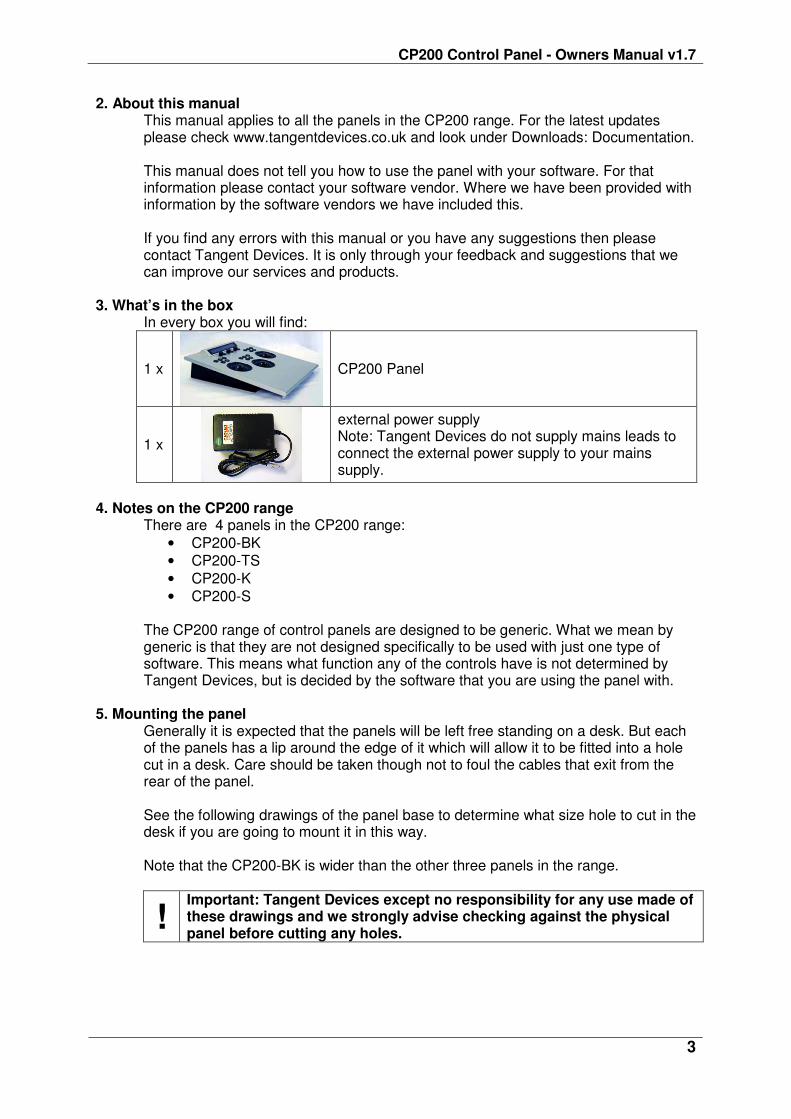
3. What’s in the box In every box you will find:
1 x
CP200 Panel
1 x
external power supply Note: Tangent Devices do not supply mains leads to connect the external power supply to your mains supply.
4. Notes on the CP200 range
There are 4 panels in the CP200 range:
• CP200-BK
• CP200-TS
• CP200-K
• CP200-S
The CP200 range of control panels are designed to be generic. What we mean by generic is that they are not designed specifically to be used with just one type of software. This means what function any of the controls have is not determined by Tangent Devices, but is decided by the software that you are using the panel with.
5. Mounting the panel
Generally it is expected that the panels will be left free standing on a desk. But each of the panels has a lip around the edge of it which will allow it to be fitted into a hole cut in a desk. Care should be taken though not to foul the cables that exit from the rear of the panel.
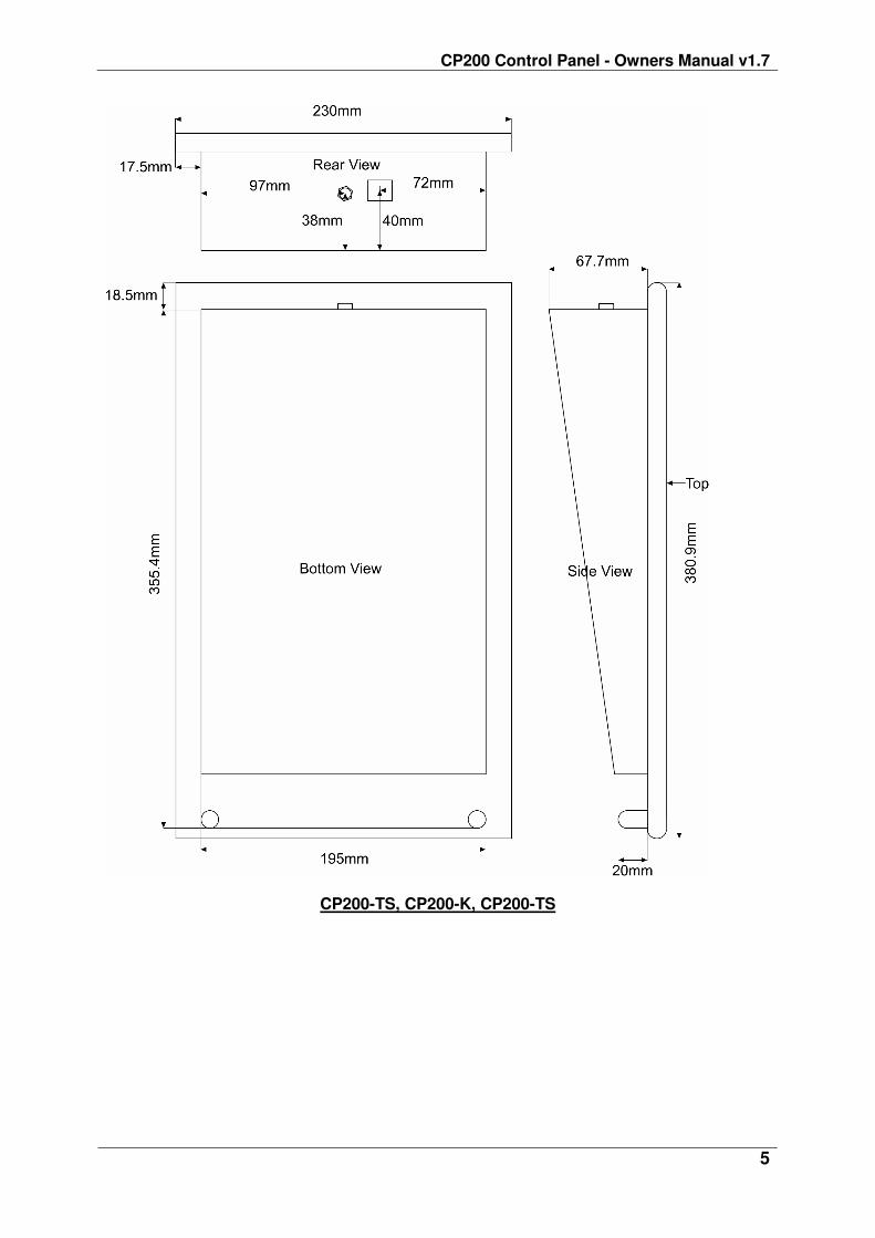
See the following drawings of the panel base to determine what size hole to cut in the desk if you are going to mount it in this way. Note that the CP200-BK is wider than the other three panels in the range.
! Important: Tangent Devices except no responsibility for any use made of these drawings and we strongly advise checking against the physical panel before cutting any holes.

CP200 Control Panel - Owners Manual v1.7
4
CP200-BK
CP200 Control Panel - Owners Manual v1.7
5
CP200-TS, CP200-K, CP200-TS
CP200 Control Panel - Owners Manual v1.7
6
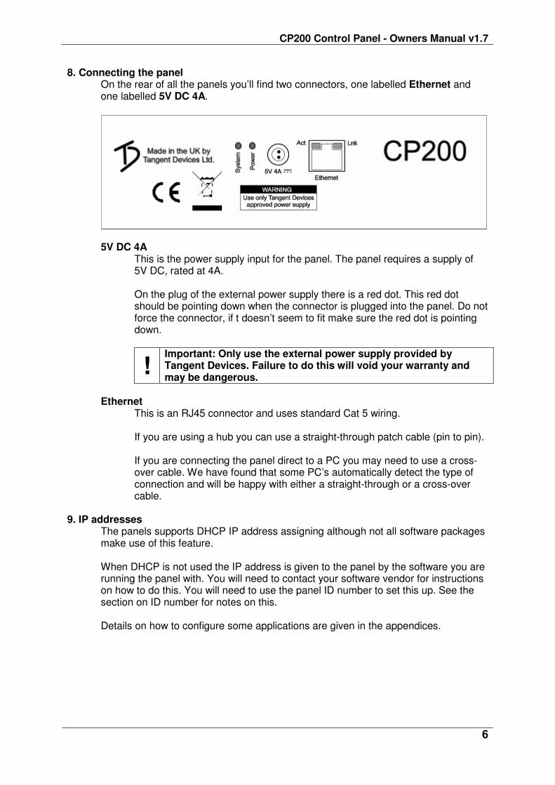
8. Connecting the panel On the rear of all the panels you’ll find two connectors, one labelled Ethernet and one labelled 5V DC 4A.
5V DC 4A This is the power supply input for the panel. The panel requires a supply of 5V DC, rated at 4A. On the plug of the external power supply there is a red dot. This red dot should be pointing down when the connector is plugged into the panel. Do not force the connector, if t doesn’t seem to fit make sure the red dot is pointing down.
! Important: Only use the external power supply provided by Tangent Devices. Failure to do this will void your warranty and may be dangerous.
Ethernet
This is an RJ45 connector and uses standard Cat 5 wiring. If you are using a hub you can use a straight-through patch cable (pin to pin). If you are connecting the panel direct to a PC you may need to use a cross-over cable. We have found that some PC’s automatically detect the type of connection and will be happy with either a straight-through or a cross-over cable.
9. IP addresses
The panels supports DHCP IP address assigning although not all software packages make use of this feature. When DHCP is not used the IP address is given to the panel by the software you are running the panel with. You will need to contact your software vendor for instructions on how to do this. You will need to use the panel ID number to set this up. See the section on ID number for notes on this. Details on how to configure some applications are given in the appendices.

CP200 Control Panel - Owners Manual v1.7
7
10. Notes on hubs, switches, routers and Ethernet The panels all run 10Mb (mega-bit) Ethernet (10 Base-T).
Generally hubs are the simplest solution to networking the panel with the host system running your software. Some routers and switches will block broadcast Ethernet packets. The panels sometimes need to be configured from the software you’re using the panel with. This configuration will use broadcast packets. If you are using a switch or a router and you’re having trouble communicating with the panel from your software, then try to find a simple hub or try a direct cable from the host PC (see the section on Connecting the panel: Ethernet). If the panel works under this simple test then it will be your router or switch that is causing the problem, in this case see if there is a setting which will enable / allow broadcast packets.
11. ID number
The ID number of the panel will be required if you are to set the IP address of the panel from the software you are using the panel with. This ID number is unique to each panel as is randomly set at the Tangent Devices factory.
The ID number is displayed on the display when the panel is first powered up. The display will show something similar to:
Panel: CP200-TS Firmware: 4.2 ID: 79
Encoder: = Key: =
In the above example the ID is the last two digits of the top line 79. 13. Rear panel indicators
On the rear of the panel there are a number of lights, these are used as follows:
System: This will flash about once a second if the panel is running properly.
Power: This will be on if power is connected to the panel.
Lnk: This will be on and green if a valid Ethernet connection has been made.
Act: This will flash orange when Ethernet packets are received by the panel.

CP200 Control Panel - Owners Manual v1.7
8
14. Test mode By default the panel will come up in a test mode when power is connected and no Ethernet cable is plugged in. This helps trouble shoot if any of the controls are not working. To enter the Test Mode, do the following: 1) Turn the panel off by unplugging the power supply. 2) Remove any Ethernet cable that you have connected to the panel.
3) Turn the panel back on by plugging in the power supply.
The display will now show something similar to the following:
Panel: CP200-TS Firmware: 4.2 ID: 79
Encoder: = Key: =
What you see will differ slightly, but basically lines above tell you the following: CP200-TS is the panel type. 4.2 is the version of the internal software (firmware) of the panel. 79 is the ID number of the panel. Checking that the controls are working
If you move any of the controls or press any of the buttons the second line of the display will change to show you the status of the control or button which has been changed. The following describes what you should see for each control or button: Knobs
If you move a knob or a trackerball the second line of the display will show something similar to this:
Encoder: 7 = 3
The first number is the ID number for that control, in this case 7. The second number is the amount it’s moved by, in this case 3. The number gets bigger the faster you turn the control. This should be positive when the knob is turned clockwise and negative if turned anti-clockwise. If the number is always -1 or 1, or doesn’t change then the knob is faulty.
Buttons
If you press a button the second line of the display will show something similar to this:
Key: 2 = DOWN
When you release the button it will show something similar to this:
Key: 2 = UP
If this doesn’t happen then the button is faulty.

CP200 Control Panel - Owners Manual v1.7
9
Trackerballs Just like the knobs, moving the outside ring of the trackerball, or the ball itself, will cause the second line of the display to show something similar to this:
Encoder: 2 = 3
The first number is the ID number for that control, in this case 2. The second number is the amount it’s moved by, in this case 3. The number gets bigger the faster you turn the control. This should be positive when the ring is turned clockwise, or the ball is moved to the right or up. It will be negative if the ring is turned anti-clockwise, or the ball is moved to the left or down. If the number is always -1 or 1, or doesn’t change then the knob is faulty. Note: due to the way the software scans the movements of the balls, it will be hard to see only changes in the left / right direction. The up / down movements are always displayed in preference by the test mode, and as it’s difficult to move the ball in just the left / right direction with out moving it up / down, you’ll always see mostly up / down changes.
15. Trouble shooting
A button doesn’t work Go into test mode and follow the button test procedure. If the button doesn’t work in the test mode then the button is broken. In this case please contact Tangent Devices. If the button works in the test mode then it may be a problem with the software you are using the panel with. Contact Tangent Devices. It may also be an Ethernet communication problem. See the trouble shooting Ethernet section.
A knob / trackerball doesn’t seem to work
Go into test mode and follow the knob test procedure. If the knob doesn’t work in the test mode then the knob is broken. In this case please contact Tangent Devices. If the knob works in the test mode then it may be a problem with the software you are using the panel with. Contact Tangent Devices. It may also be an Ethernet communication problem. See the trouble shooting Ethernet section.
System light doesn’t flash
Check there is power going to the panel. If there is power going to the panel and the system light is not flashing then the panel is faulty. In this case please contact Tangent Devices.
Power light isn’t on First check that the power supply connector is fully inserted into the panel.
Next, check that the light on the external power supply is on. If it’s not then check that it’s plugged into the mains and that any fuses are ok.
CP200 Control Panel - Owners Manual v1.7
10
If the light on the external power supply is on but the power light on the panel is still not on, then the panel is at fault. In this case please contact Tangent Devices. If the light on the external power supply is off but it is being supplied with mains power then the external power supply is at fault. In this case please contact Tangent Devices.
My software isn’t communicating with the panel
Generally problems with communication are related to setting up your software to talk to the panel. Refer to your software vendors instructions for doing this. Read the previous sections of this manual relating to the Ethernet connection, hubs routers and switches, IP addresses and ID number. Lnk light: When you plug an Ethernet cable into the RJ45 connector on the panel, and the other end of the cable is connected to a hub/host computer that is powered on, the green LNK light on the RJ45 connector will light up. If it does not light up then check the cable is not damaged and the connectors are fully inserted into their plugs. Make sure the hub/host computer is powered up. Act light: When there is communication taking place with the host computer, the ACT light will flash as the panel receives information. If it doesn’t flash then make sure the ACT light is on (see above) and that the software is running on the host computer and it has been set up to talk to the panel. If after doing the above, and taking any relevant action, you’re still having trouble, then contact Tangent Devices.
16. Care of your panels
Your CP200 panels should not be cleaned with harsh abrasives or chemical cleaning products. If they become dirty wipe them with a soft damp cloth.

CP200 Control Panel - Owners Manual v1.7
11
Appendix 1. Connecting the panels to Final Cut Color (Apple) Connection The panels cannot be connected to the secondary Ethernet port of your Mac Pro; they must be connected to the computer’s primary Ethernet port, if necessary through a hub or switch if you need to share the port with an Internet Connection. To set up the CP200 series panels for use with Color 1. Connect each of the CP200 panels to your computer as detailed above.
2. Before you open Color, turn on each of the panels and write down the two or
three character ID numbers that appear on the display of each. You’ll use each device’s ID number to setup Color to communicate with the panel. Note: The ID numbers that Color uses to connect to the CP200 surfaces are not the Serial Numbers that appear on the back of the panels.
3. Open Color. If you’re opening Color for the first time, you’ll be presented with the Control Surface Startup dialog. If you’ve already opened Color and have disabled the option for making the dialog appear, you’ll need to click Show Control Surface Dialog button in the User Prefs tab of the Setup room.
4. Choose “Tangent Devices – CP200” from the Control Surface popup menu. Each CP200 device that Color is compatible with appears with an Enabled checkbox with two fields: one for the ID number that you wrote down previously, and one for the panel’s IP address.

CP200 Control Panel - Owners Manual v1.7
12
5. For each CP200 device connected: Select its checkbox. Type its ID number into the corresponding field, and press Enter. Type an IP address into the corresponding field, and press Enter. Notes: The first three period-delimited numbers in the IP address must match the first three numbers that are used on the Primary Ethernet interface of the Mac Pro. If you’re not sure what values to use, you should check to see what IP address is used by the Mac’s Primary Ethernet interface and base the panels’ IP addresses on that, making sure that you change the last number for each panel to make each addresses unique.
6. Important: Enter a Gateway IP address for this subnet. Even if there is no
gateway on the network a value within the subnet must be entered. e.g. for a subnet range of 10.10.10.x a gateway value of 10.10.10.0 could be used.
7. Click Yes.
After you click Yes, Color connects with the control surfaces on the network. If this is successful then each panel’s display should now go blank. The CP200 panels are now ready for use with Color.
For details of the functions that map to each of the controls on the panels please see your Final Cut Studio – Color manual.

CP200 Control Panel - Owners Manual v1.7
13
Appendix 2. Connecting the panels to Bones (Thomson) The information in this appendix has been provided by Thomson and reproduced with their permission.
External Control Panel (TANGENT) Configuration The Tangent panels are connected to the Bones workstation over Ethernet using UDP over IPv4 protocol. The network traffic between the Tangent panel and the Bones workstation can be rather high! In order not to overflow the house network the Tangent panels should be connected to an own separate network port of the Bones workstation. This own network port MUST NOT be the port talking to the Spirit4K! If no other free network port is available the Tangent panel may be connected to the main network port eth0 talking to the house network. In this case the Bones workstation should be separated from the house network via a router! The communication between the Bones software application and the Tangent panels is initiated using Multicast/Broadcast messages. If the Tangent panel is not been connected via the main network port of the Bones workstation a route must be set for the connection of the two. This can be done the following way: On the Bones workstation terminal window enter as user root the following line: ‘route add default gw network-port-address’
Where the string network-port-address has to be replaced by the IP address of the network port talking to the Tangent Panels. PANEL_IDs required for Bones.config entries can be detected by connecting power to the panels. The ID is shown in the display of the panels. Bones.config entries: ################################################### # External panel devices configuration section # # Panels connected to the host Bones is running on can be configured here # At the moment this only affects panels from TangentDevices ################################################### # NUM_PANELS 2 # PANEL_ID_1 2 # serial of the panel # PANEL_TYPE_1 CP200T # allowed values # CP200T and # CP200B # PANEL_IP_1 192.168.0.7 # the IP address # the panel # should be assigned # to # PANEL_BROADCAST_IP_1 192.168.0.255 # the corresponding # broadcast IP # PANEL_ID_2 1 # PANEL_TYPE_2 CP200B # PANEL_IP_2 192.168.0.5 # PANEL_BROADCAST_IP_2 192.168.0.255 # Loop frequency for TangentDevices panels. Value can be 1 to 40 (Hz). # Values out of this range will be ignored so that default is used # PANEL_LOOP_FREQUENCY_TANGENT # default 25
TangentCP200default.hk file Configuration The TangentCP200default.hk file provides a default configuration for the Tangent CP200 Transport and Trackerball panels. How to use this file: Before the settings can be imported into Bones it is necessary to edit the TangentCP200default.hk file first.

CP200 Control Panel - Owners Manual v1.7
14
Each line contains a term like PanelXX+Z or PanelYY+Z, where Z is the hotkey ID (which is already given and therefore not need to be changed). It is important to replace the XX and YY placeholders by the actual panel ID. XX needs to be replaced by the ID of the Trackerball panel (CP200B-series) and YY by the ID of the Transport panel (CP200T-series). The ID of each panel is shown on panel's LCD when the power cable is connected. Please rename the edited TangentCP200default.hk file. Import into Bones: In Bones' setup page select the "Hot Keys" menu item. In the section on the right side open the file browser dialog by pressing the "Import..." button. Go to the location of the TangentCP200default.hk file (/usr/thomson/etc/config/tangent) and open the file. The imported settings affect some of the panel assignments in the following hotkey sections: "Crop Node" "Transform Node" "Primary Color Correction" "Play Controls" "Global" NOTE! The file also contains the defaults for keyboard assignments of the affected functions. So any existing keyboard assignment will be overwritten by its default. It is recommended to import this file before changing any default assignment manually.

CP200 Control Panel - Owners Manual v1.7
15
Appendix 3. Connecting the panels to SpeedGrade OnSet (Iridas) The information in this appendix has been provided by Iridas and reproduced with their permission.
Connecting the CP200-BK to your laptop or workstation
Before you can use the CP200-BK with SpeedGrade OnSet make sure the panel is turned on and shows Panel type, Firmware and ID in its display. Connect the panel with an ethernet cable to your laptop or workstation. If you run a workstation that uses several ethernet ports we recommend using a dedicated ethernet port and not connecting the panel via a HUB.
The Network Setup: Setting a fixed IP address A: Apple OS X
Open the system control panel. Then open the network control panel. If there are multiple network connections check which one matches the ethernet port you are using to physically connect with the panel, then click on the entry in the network panel. Click on “Configure” to open the settings panel for this ethernet port. Use a static IP address and subnet mask. You can leave all the other fields blank. If you use any 3rd party Firewall Software please make sure to set exceptions for this connection.
Click on “Apply Now” once you’re done with entering IP address and subnet mask, then go to the Changing the Tangent Settings within SpeedGrade OnSet section below to finish the Setup of your panel.

CP200 Control Panel - Owners Manual v1.7
16
B: Microsoft Windows
Under Windows open the network connections (click Start > open the “Control Panel” > open “Network connections”). If there are several Local area connections check which one becomes active when connecting the panel. Now double click on the correct Local Area Connection. Click on “Properties.” In the new window check for TCPIP, double click to open. Make the changes shown in the illustration below:
Use a static IP address and subnet mask. You can leave all the other fields blank. If this connection is set to use Windows Firewall, turn it off for this connection (check in Local Area Connection Properties under Advanced). If you use additional Firewall Software please make sure to set exceptions for this connection.
CP200 Control Panel - Owners Manual v1.7
17
Changing the Panel Settings within SpeedGrade OnSet
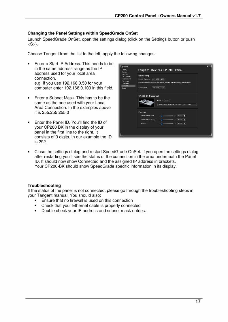
Launch SpeedGrade OnSet, open the settings dialog (click on the Settings button or push <S>). Choose Tangent from the list to the left, apply the following changes:
• Enter a Start IP Address. This needs to be in the same address range as the IP address used for your local area connection. e.g. If you use 192.168.0.50 for your computer enter 192.168.0.100 in this field.
• Enter a Subnet Mask. This has to be the same as the one used with your Local Area Connection. In the examples above it is 255.255.255.0
• Enter the Panel ID. You’ll find the ID of your CP200 BK in the display of your panel in the first line to the right. It consists of 3 digits. In our example the ID is 292.
• Close the settings dialog and restart SpeedGrade OnSet. If you open the settings dialog after restarting you’ll see the status of the connection in the area underneath the Panel ID. It should now show Connected and the assigned IP address in brackets. Your CP200-BK should show SpeedGrade specific information in its display.
Troubleshooting If the status of the panel is not connected, please go through the troubleshooting steps in your Tangent manual. You should also:
• Ensure that no firewall is used on this connection
• Check that your Ethernet cable is properly connected
• Double check your IP address and subnet mask entries.