owner’s operation and installation manual · pdf fileburner model valve type fuel type...
TRANSCRIPT

1
Owner’s Operation and Installation Manual
MVF40 certified as a Universal Firebox ANSI Z21.91-2007Listed Certified for USA
UNVENTED (VENT-FREE) MULTI-SIDED FIREBOX Enclosure For Gas-Fired Decorative Type Unvented Room Heaters
Vent Free: GLMVF40MVN, GLMVF40MVPMVFBL4040MVN, MVFBL4040MVP, MVFBR4040MVN, MVFBR4040MVP
Vent-free: Certified to USA standards: ANSI Z21.11.2 - 2007
Warning
If the information in this manual is not followed exactly, a fire or explosion my result causing propertydamage, personal injury, or loss of life.– Do not store or use gasoline or other flammable vapors and
liquids in the vicinity of this or any other appliance.– WHAT TO DO IF YOU SMELL GAS• Do not try to light any appliance.• Do not touch any electrical switch; do not use any phone in
your building.• Immediately call your gas supplier from a neighbor’s
phone. Follow the gas supplier’s instructions.• If you cannot reach your gas supplier, call the fire
department.– Installation and service must be performed by a qualified
installer, service agency, or the gas supplier.
WarningImproper installation, adjustment, alteration, service, or maintenancecan cause injury or property damage. Refer to this manual for correct installation and operationalprocedures. For assistance oradditional information consult aqualified installer, service agency, orthe gas supplier.
WarningThis is an unvented gas-fired heater.It uses air (oxygen) from the room inwhich it is installed. Provisions foradequate combustion and ventilationair must be provided. Refer to section
Save this manual for future reference • 2340 Logan Ave., Winnipeg, MB, Canada, Phone: (204) 632-1962 • Printed in Canada • PART #40VF-MANJuly 27, 2009
WarningCarefully review the instructionssupplied with the decorative type
unvented log set room heater for theminimum size requirement.
DO NOT INSTALL THE APPLIANCEIN THIS FIREBOX UNLESS THISFIREBOX MEETS THE MINIMUM
DIMENSIONS REQUIRED FOR THEINSTALLATION
WarningFOR USE ONLY WITH
A LISTED GAS-FIRED UNVENTEDDECORATIVE ROOM HEATER
NOT TO EXCEED40,000 BTU/H.
DO NOT BUILD A WOOD FIRE
This appliance must beinstalled by a licensedplumber or gas fitter inthe Commonwealth of
Massachusetts and meetthe requirements of 527CMR 30 and 248 CMR.
INSTALLER: Leave this manual with the appliance.CONSUMER: Retain this manual for future reference.

2
3
Why does my fireplace or stove give off odour?
It is normal for your fireplace to give off some odour. This is due to the curing of the paint, adhesives,silicones and any undetected oil from the manufacturing process as well as the finishing materials usedwith the installations (e.g. marble, tile and the adhesives used to adhere this product to the walls can reactwith heat and cause odours).
It is recommended that you burn your gas fireplace or stove for a minimum of four hours at a time withthe fan off after the curing of the paint has been completed. These odours can last upward to 40 hours ofburn time, keep burning at a minimum of four hours per use until odours dissipate.
About curing of the paint
Your stove or fireplace has been painted with the highest quality silicone stove paint. This paint driesquickly in 15-20 minutes when first applied at the factory. However, due to the high temperature siliconecomponents, the paint will cure when heat is applied to the appliance as it is first used. The following information applies to the curing process to get the paint fully hard and durable.
Fire the appliance four successive times for 10 minutes each firing and a 5 minute cool down betweeneach. Be aware during log and firebox paint curing that a white deposit may be developing on the insideof the glass doors. It is important to remove this white deposit from the glass doors with an appropriatecleaner to prevent build-up (such as Windex or a commercial fireplace glass cleaner).
• Babies, small children, pregnant women and pets should leave the area during the cure phase.
• Ventilate well, open doors and windows.
• Do not touch during curing.
Noise coming from the fireplace?
• Noise caused by metal expanding and contracting as it heats up and cools down, similar to the soundproduced by a furnace or heating duct. This noise does not affect the operation or longevity of yourfireplace.
• Different types and thicknesses of steel will expand and contract at different rates resulting in“cracking” and “ticking” sounds throughout the heating and cooling periods.
• You should also be aware that as temperatures change within the unit these sounds will likely re-occur. Again this is normal for steel fireboxes, and is not a defect.
Cleaning the Glass
During the first few fires, a white film may develop on the glass front, as part of the curing process. Theglass should be cleaned after the unit has cooled down or the film can bake on and become very difficultto remove. Use a non-abrasive cleaner and do not attempt to clean the glass while it is hot.
PRE-INSTALLATION QUESTIONS and ANSWERS

4
TABLE OF CONTENTS
SECTION PAGE
Burner System Options . . . . . . . . . . . . . . . . . . . . . . . . . . . . . . . . . . . . . . . . . . . . . . . . . . . . . . . . . . . . . . . . . . . . . . . .5
Safety Information . . . . . . . . . . . . . . . . . . . . . . . . . . . . . . . . . . . . . . . . . . . . . . . . . . . . . . . . . . . . . . . . . . . . . . . . . . . .6
Local Codes . . . . . . . . . . . . . . . . . . . . . . . . . . . . . . . . . . . . . . . . . . . . . . . . . . . . . . . . . . . . . . . . . . . . . . . . . . . . .7
For Your Safety Read Before Lighting . . . . . . . . . . . . . . . . . . . . . . . . . . . . . . . . . . . . . . . . . . . . . . . . . . . . . . . .7
Framing Specifications . . . . . . . . . . . . . . . . . . . . . . . . . . . . . . . . . . . . . . . . . . . . . . . . . . . . . . . . . . . . . . . . . . . . . . . . 8
Framing Parts . . . . . . . . . . . . . . . . . . . . . . . . . . . . . . . . . . . . . . . . . . . . . . . . . . . . . . . . . . . . . . . . . . . . . . . . . . . . .9-10
Dimensions . . . . . . . . . . . . . . . . . . . . . . . . . . . . . . . . . . . . . . . . . . . . . . . . . . . . . . . . . . . . . . . . . . . . . . . . . . . . . . . .11
Installing . . . . . . . . . . . . . . . . . . . . . . . . . . . . . . . . . . . . . . . . . . . . . . . . . . . . . . . . . . . . . . . . . . . . . . . . . . . . . . . . . . 12
Installation Clearances . . . . . . . . . . . . . . . . . . . . . . . . . . . . . . . . . . . . . . . . . . . . . . . . . . . . . . . . . . . . . . . . . . . 13
Installing by Framing Fireplace . . . . . . . . . . . . . . . . . . . . . . . . . . . . . . . . . . . . . . . . . . . . . . . . . . . . . . . . . . . . 14
Peninsula Framing . . . . . . . . . . . . . . . . . . . . . . . . . . . . . . . . . . . . . . . . . . . . . . . . . . . . . . . . . . . . . . . . . . . . . . 16
See-Through Framing . . . . . . . . . . . . . . . . . . . . . . . . . . . . . . . . . . . . . . . . . . . . . . . . . . . . . . . . . . . . . . . . . . .17
Bay Peninsula Framing . . . . . . . . . . . . . . . . . . . . . . . . . . . . . . . . . . . . . . . . . . . . . . . . . . . . . . . . . . . . . . . . . . .18
Corner Framing . . . . . . . . . . . . . . . . . . . . . . . . . . . . . . . . . . . . . . . . . . . . . . . . . . . . . . . . . . . . . . . . . . . . . . . . .19
Universal Firebox . . . . . . . . . . . . . . . . . . . . . . . . . . . . . . . . . . . . . . . . . . . . . . . . . . . . . . . . . . . . . . . . . . . . . . .20
Air for Combustion and Ventilation . . . . . . . . . . . . . . . . . . . . . . . . . . . . . . . . . . . . . . . . . . . . . . . . . . . . . . . . . . . . .21
Providing Adequate Ventilation . . . . . . . . . . . . . . . . . . . . . . . . . . . . . . . . . . . . . . . . . . . . . . . . . . . . . . . . . . . .21
Determining Air Flow for Firebox Location . . . . . . . . . . . . . . . . . . . . . . . . . . . . . . . . . . . . . . . . . . . . . . . . . . .21
Ventilation Air from Inside Building . . . . . . . . . . . . . . . . . . . . . . . . . . . . . . . . . . . . . . . . . . . . . . . . . . . . . . . .23
Ventilation Air from Outdoors . . . . . . . . . . . . . . . . . . . . . . . . . . . . . . . . . . . . . . . . . . . . . . . . . . . . . . . . . . . . .24
Installing Gas Line . . . . . . . . . . . . . . . . . . . . . . . . . . . . . . . . . . . . . . . . . . . . . . . . . . . . . . . . . . . . . . . . . . . . . . . . . . .25
Installing MVFB 4040 Burner System . . . . . . . . . . . . . . . . . . . . . . . . . . . . . . . . . . . . . . . . . . . . . . . . . . . . . . . . . . .26
Cleaning and Servicing of Burner /ODS Pilot . . . . . . . . . . . . . . . . . . . . . . . . . . . . . . . . . . . . . . . . . . . . . . . . .26
Installing MVFB4040 Burner System & LOGF38 . . . . . . . . . . . . . . . . . . . . . . . . . . . . . . . . . . . . . . . . . . . . . . . . . .27
LOGF38 Log Placement for MVFB4040 Burner System . . . . . . . . . . . . . . . . . . . . . . . . . . . . . . . . . . . . . . . . . .28-29
Installing GLMVF40 Burner System . . . . . . . . . . . . . . . . . . . . . . . . . . . . . . . . . . . . . . . . . . . . . . . . . . . . . . . . . . . .30
LOGC31 Log Placement for GLMVF40 Burner Grate . . . . . . . . . . . . . . . . . . . . . . . . . . . . . . . . . . . . . . . . . . . .31-32
Millivolt System, Lighting Instructions & Burner Control . . . . . . . . . . . . . . . . . . . . . . . . . . . . . . . . . . . . . . . . . . . .33
Installing Fan Kit, Screen Door, Shield + Hood . . . . . . . . . . . . . . . . . . . . . . . . . . . . . . . . . . . . . . . . . . . . . . . . .34-35
Illustrated Parts List . . . . . . . . . . . . . . . . . . . . . . . . . . . . . . . . . . . . . . . . . . . . . . . . . . . . . . . . . . . . . . . . . . . . . . .36-38
Accessory and Parts List . . . . . . . . . . . . . . . . . . . . . . . . . . . . . . . . . . . . . . . . . . . . . . . . . . . . . . . . . . . . . . . . . . .39-40
Troubleshooting . . . . . . . . . . . . . . . . . . . . . . . . . . . . . . . . . . . . . . . . . . . . . . . . . . . . . . . . . . . . . . . . . . . . . . . . . .41-42
Warranty . . . . . . . . . . . . . . . . . . . . . . . . . . . . . . . . . . . . . . . . . . . . . . . . . . . . . . . . . . . . . . . . . . . . . . . . . . . . . . . . . . .43

5
BURNER SYSTEM OPTIONSSee chart below for required burner system:
TABLE 1 - The MVF40 is also approved as a Universal Vent Free Box. See page 20 for more information.
MVF40 Vent Free Firebox Required burner system: (Select from below to complete the fireplace)
OPTION 2MVFBL/R 40 Burner Systems - control are hidden and accessed through bottom grill.
LOGF38 Log Set Fibre Five Piece - Required for MVFBL/R 4040 Burner Systems
Burner Model Valve Type Fuel Type BTU – Input Min/Max Inlet Manifold Pressure Orifice Size Primary Air
Left Hand BurnerMVFBL4040MVN Millivolt Natural Gas 26,000-38,000 5.5/10” 1.6-3.5” 32 0.25MVFBL4040MVP Millivolt Liquid Propane 26,000-34,000 11/13” 6.3-10” 50 Full Open
Right Hand BurnerMVFBR4040MVN Millivolt Natural Gas 26,000-38,000 5.5/10” 1.6-3.5” 32 0.25MVFBR4040MVP Millivolt Liquid Propane 26,000-34,000 11/13” 6.3-10” 50 Full Open
OPTION 1GLMVF40 Log Grate Burner System - controls are accessed from firebox on raised grate. Pull screen are recommended.
LOGC31 Log Set 7 Piece required for GLMVF40 Burner Systems.
Burner Model Valve Type Fuel Type BTU – Input Min/Max Inlet Manifold Pressure Orifice Size Primary Air
GLMVF40MVN Millivolt Natural Gas 29,900-38,225 5.5/10” 1.6-3.5” 32 1/8” Open
GLMVF40MVP Millivolt Liquid Propane 24,200-30,500 11/13” 6.3-10” 49 1/2” Open
This appliance is equipped for (Natural or Propane) Gas. Field conversion is not permitted.

SAFETY INFORMATION WARNINGS
6
WARNINGSImportant: Read this owner’s manual carefully and completelybefore trying to assemble, operate, or service this firebox.Improper use of this firebox can cause serious injury or deathfrom burns, fire, explosion, electrical shock, and carbon monoxidepoisoning.
Early signs of carbon monoxide poisoning resemble the flu, with headaches, dizziness, and / or nausea. If you have thesesigns, the heater may not be working properly. Get fresh air atonce! Turn off gas appliance. Have appliance serviced. Somepeople (such as pregnant women, persons with heart or lungdisease, persons with anemia and those at high altitudes) are moreaffected by carbon monoxide than others. Make certain you readand understand all warnings.
1. Use correct gas type for your appliance. Do not convert fromone gas type to another.
2. If this appliance is for use with Propane gas, do not placepropane supply tank(s) inside any structure. Locate propanesupply tank(s) outdoors.
3. If you smell gas:– Shut off gas supply.– Do not try to light any appliance.– Do not touch any electrical switch; do not use any phone inyour building.– Immediately call your gas supplier from a neighbor’sphone. Follow the gas supplier’s instructions.– If you cannot reach your gas supplier, call the firedepartment.
4. Do not use this appliance for burning trash or cooking. Neverplace matches, paper, garbage, or any other material on topof logs or logs into flame.
5. Warning: Always operate appliance with front fireplacescreens closed.
6. Make sure any safety screen or guard removed for servicingis in place before running appliance.
7. Never run appliance in a small, closed room. Open the doorinto next room to help ventilate.
8. If appliance shuts off, do not relight until you provide freshoutside air. If appliance keeps shutting off, have it serviced.
9. Do not run appliance:– where flammable liquids or vapors are used or stored.– under dusty conditions.
10. Surface of appliance becomes very hot when operating. Keepchildren and adults away from hot surface. Appliance willremain hot for some time after shutdown. Allow surface tocool before touching.
11. Do not use this appliance if any part has been submergedunder water. Immediately call a qualified technician toinspect the appliance and to replace any part of the controlsystem and gas control which has been under water.
12. The installation must conform with local codes or, in the absenceof local codes, with the National Fuel Gas Code, ANSI Z223.1.
13. Never install the appliance:– in a bedroom, bathroom, mobile home, or recreationalvehicle.– where curtains, furniture, clothing, or other flammableobjects are less than forty-two inches (42”) from the front
of the appliance.– in high traffic areas.– in windy or drafty areas.
14. Disconnect the appliance and its individual shut off valvefrom the gas supply piping system during any pressuretesting of that system at test pressures in excess of 1/2 psig,(3.5kPa).
15. Isolate the appliance from the gas supply piping system byclosing its individual manual shut off valve during any pressure testing of the the gas supply piping system at testpressure equal or less than 1/2 psig,(3.5kPa).
16. Do not use any type of after-market blower that fits inside thefireplace. Drafts created by these type of blowers may causesooting.
17. Turn off appliance and let cool before servicing. Only aqualified service person should install, service and repairappliance
DANGER
CARBON MONOXIDE POISONINGMAY LEAD TO DEATH!
NOTE: It is recommended that a Carbon Monoxide (CO)Detector be installed in or near bedrooms and on all levels ofyour home. Place a detector about 15 feet (4.5 meters) outsidethe room that houses your gas appliance.
This appliance is equipped for(Natural or Propane) Gas.
Field conversion is not permitted.
Warning: Failure to position parts in accordancewith these diagrams or failure to use only part
specifically approved with this heater may result inproperty damages or personal injury.

7
WARNINGIf you do not follow these instructions exactly, a fire orexplosion may result causing property damage,personal injury or loss of life.
18. Inspect the appliance before use and at least annually by a professional service person. Frequent cleaning may be required due toexcessive lint from carpeting, bedding material, etc. It is important that control compartment, burner and circulating air passage ofthe appliance be kept open.
19. When operated for the first time, there will be some smell from the appliance. This will diminish and disappear after a few hours ofoperation.
20. Warning: Do not allow fans to blow directly into the fireplace. Avoid any drafts that alter flame patterns.
21. Warning: Do not use a blower insert, heat exchanger insert or other accessory not approved for use with this heater.
22. The firebox canopy must not be replaced with a canopy which may be provided with the decorative type UNVENTED room heater.
23. Warning: Do not operate ceiling fans in same room as the vent free appliance.
24. Due to high temperatures, the appliance should be located out of traffic and away from furniture and draperies.
25. Children and adults should be alerted to the hazard of high surface temperature and should stay away to avoid burns or clothingignition.
26. Young children should be carefully supervised when they are in the same room with the appliance.
27. Do not place clothing or other flammable material on or near the appliance.
28. Any safety screen or guard removed for servicing an appliance must be replaced prior to operating the heater (see 1.2.3).
29. Installation and repair should be done by a qualified service person. The appliance should be inspected before use and at leastannually by a professional service person. More frequent cleaning may be required due to excessive lint form carpeting, beddingmaterial, etc. It is imperative that control compartments, burners and circulating air passageways of the appliance be kept clean.
30. “Warning: Any change to this heater or its controls can be dangerous.”
31. Must be installed by a licensed gasfitter in the Commonwealth of Massachusetts. Complies to code 527 CMR
32. Unvented gas fired appliances may be used only for supplemental heat and/or decorative purposes and under nocircumstances shall they provide a primary heat source.
33. Warning: Failure to keep the primary air opening(s) of the burner(s) clean may result in sooting and property damage.
LOCAL CODESInstall and use fireplace with care. Follow all local codes. In the absence of local codes, use the latest edition of The National Fuel Gas Code ANSI Z223.1, also known asNFPA 54*. Firebox must be electrically grounded in accordance with the National Electrical Code, ANSI/NFPA 70 (latest edition).
*Available from:
American National Standards Institute, Inc. National Fire Protection Association, Inc.1430 Broadway Batterymarch ParkNew York, NY 10018 Quincy, MA 02260
FOR YOUR SAFETY READ BEFORE LIGHTINGA. This appliance has a pilot which must be lighted by hand. When lighting the pilot, follow these instructions exactly.
B. Before lighting, smell all around the appliance area for gas. Be sure to smell next to the floor because some gas isheavier than air and will settle on the floor.
What to do if you smell gas
• Do not try to light any appliance.• Do not touch any electric switch; do not use any phone in your building.• Immediately call your gas supplier from a neighbor’s phone. Follow the gas supplier’s instructions.• If you cannot reach your gas supplier, call the fire department.
C. Use only your hand to push in or turn the gas control knob. Never use tools. If the knob will not push in or turn by hand,don’t try to repair it, call a qualified service technician or gas supplier. Force or attempted repair may result in a fire orexplosion.
D. Do not use this appliance if any part has been under water. Immediately call a qualified service technician to inspect theappliance and to replace any part of the control system and any gas control which has been under water.

8
FRAMING SPECIFICATIONSSee Page 9 for required parts for installation.
FIGURE 1
Framing Clearances to Fireplace: Bottom – 0 / Sides – 0 to standoffs / Top – 0 to standoffs / Adjacent side wall – 2” / Front of fireplace to ceiling – 41”.
Right Corner Top ViewWithout 2 x 4 Framing
Left Corner Top View using 2 x 4 Framing
See Thru top ViewWithout 2 x 4 Framing
See Thru Top View using2 x 4 Framing
Island Top View
PLACEMENT AND FRAMINGNote: When not using nailing tabsyou may place Heatshield directly
against existing wall and screwunit to the floor using holes located
in the bottom of unit
Bay Peninsulawithout
2 x 4 Framing
Bay PeninsulaUsing 2 x 4
Framing
Right Corner Top ViewUsing 2 x 4 Framing
Peninsula Top ViewUsing 2 x 4 Framing
Peninsula Top ViewWithout 2 x 4 Framing
Left Corner Top ViewWithout 2 x 4 Framing
4

9
FRAMING PARTSREQUIRED PARTS FOR INSTALLATIONS OF MULTI-SIDED FIREPLACE
MVF40 Multi-Sided Vent Free Firebox
Choose Your installation (as shown on Page 8, and see below for required parts.)
1. RIGHT CORNER INSTALLATIONMVF40CK Corner Kit - One Large Side Open, One Small Side OpenChoose Natural Gas or Liquid Propane Burner:
Choose Grill Kits or Panel Kits:MGCKBP Grill Kit Corner - Classic Polish Brass (Two Sets)MGCKBA Grill Kit Corner - Classic Antique Brass (Two Sets)MGCKBC Grill Kit Corner - Classic Chrome (Two Sets)MGCKBL Grill Kit Corner - Black (Two Sets)MGCKPB Grill Kit Corner - Polish Brass (Two Sets)MGCKAB Grill Kit Corner - Antique Brass (Two Sets)MGCKCR Grill Kit Corner - Chrome (Two Sets)MVF40PCK Panel Kit for Corner Kit - Black (Two Sets)
2. LEFT CORNER INSTALLATIONMVF40CK Corner Kit - One Large Side Open, One Small Side OpenChoose Natural Gas or Liquid Propane Burner:
Choose Grill Kits or Panel Kits:MGCKBP Grill Kit Corner - Classic Polish Brass (Two Sets)MGCKBA Grill Kit Corner - Classic Antique Brass (Two Sets)MGCKBC Grill Kit Corner - Classic Chrome (Two Sets)MGCKBL Grill Kit Corner - Black (Two Sets)MGCKPB Grill Kit Corner - Polish Brass (Two Sets)MGCKAB Grill Kit Corner - Antique Brass (Two Sets)MGCKCR Grill Kit Corner - Chrome (Two Sets)MVF40PCK Panel Kit for Corner Kit - Black (Two Sets)
BURNER SYSTEM & LOG SET (REQUIRED FOR MVF40 FIREBOX)
OPTION 1GLMVF40MVN Vent Free Multiview Burner System – Millivolt Valve 38,000 BTU/HR Natural GasGLMVF40MVP Vent Free Multiview Burner System – Millivolt Valve 35,000 BTU/HR Liquid PropaneLOGC31 Log Set LOGC31 required for GLMVF40 Burner System
OPTION 2MVFBL4040MVN Vent Free Left Burner System – Millivolt Valve 38,000 BTU/HR Natural GasMVFBL4040MVP Vent Free Left Burner System – Millivolt Valve 35,000 BTU/HR Liquid Propane
LOGF38 Log Set required for MVFB40 R/L Burner System
This appliance is equipped for (Natural or Propane) Gas. Field conversion is not permitted.
BURNER SYSTEM & LOG SET (REQUIRED FOR MVF40 FIREBOX)
OPTION 1GLMVF40MVN Vent Free Multiview Burner System – Millivolt Valve 38,000 BTU/HR Natural GasGLMVF40MVP Vent Free Multiview Burner System – Millivolt Valve 35,000 BTU/HR Liquid PropaneLOGC31 Log Set LOGC31 required for GLMVF40 Burner System
OPTION 2MVFBR4040MVN Vent Free Right Burner System – Millivolt Valve 25,900/38,225 Natural GasMVFBR4040MVP Vent Free Right Burner System – Millivolt Valve 24,200/30,500 Liquid Propane
LOGF38 Log Set required for MVFB40 R/L Burner System

10
FRAMING PARTS (continued)
3. BAY PENINSULA INSTALLATIONMVF40BK Bay Peninsula Kit - One Large Side Open, Two Small Sides OpenChoose Natural Gas or Liquid Propane Burner:
Choose Grill Kits or Panel Kits:MGBKBP Grill Kit Bay Peninsula - Classic Polish Brass (Three Sets)MGBKBA Grill Kit Bay Peninsula - Classic Antique Brass (Three Sets)MGBKBC Grill Kit Bay Peninsula - Classic Chrome (Three Sets)MGBKBL Grill Kit Bay Peninsula - Black (Three Sets)MGBKPB Grill Kit Bay Peninsula - Polish Brass (Three Sets)MGBKAB Grill Kit Bay Peninsula - Antique Brass (Three Sets)MGBKCR Grill Kit Bay Peninsula - Chrome (Three Sets)MVF40PBK Panel Kit Bay Peninsula Kit - Black (Three Sets)
4. SEE-THROUGH INSTALLATIONMVF40SK See Through Kit - Two Large Sides OpenChoose Natural Gas or Liquid Propane Burner:
Choose Grill Kits or Panel Kits:MGSKBP Grill Kit See-Through - Classic Polish Brass (Two Sets)MGSKBA Grill Kit See-Through - Classic Antique Brass (Two Sets)MGSKBC Grill Kit See-Through - Classic Chrome (Two Sets)MGSKBL Grill Kit See-Through - Black (Two Sets)MGSKPB Grill Kit See-Through - Polish Brass (Two Sets)MGSKAB Grill Kit See-Through - Antique Brass (Two Sets)MGSKCR Grill Kit See-Through - Chrome (Two Sets)MVF40PSK Panel Kit See-Through - Black (Two Sets)
BURNER SYSTEM & LOG SET (REQUIRED FOR MVF40 FIREBOX)
OPTION 1GLMVF40MVN Vent Free Multiview Burner System – Millivolt Valve 38,000 BTU/HR Natural GasGLMVF40MVP Vent Free Multiview Burner System – Millivolt Valve 35,000 BTU/HR Liquid PropaneLOGC31 Log Set LOGC31 required for GLMVF40 Burner System
OPTION 2MVFBR4040MVN Vent Free Right Burner System – Millivolt Valve 25,900/38,225 Natural GasMVFBR4040MVP Vent Free Right Burner System – Millivolt Valve 24,200/30,500 Liquid Propane
MVFBL4040MVN Vent Free Left Burner System – Millivolt Valve 38,000 BTU/HR Natural GasMVFBL4040MVP Vent Free Left Burner System – Millivolt Valve 35,000 BTU/HR Liquid PropaneLOGF38 Log Set required for MVFB40 R/L Burner System

11
5. PENINSULA INSTALLATIONMVF40PK Peninsula Kit - Two Large Sides Open, One Small Side OpenChoose Natural Gas or Liquid Propane Burner:
Choose Grill Kits or Panel Kits: MGPKBP Grill Kit Peninsula - Classic Polish Brass (Three Sets)MGPKBA Grill Kit Peninsula - Classic Antique Brass (Three Sets)MGPKBC Grill Kit Peninsula - Classic Chrome (Three Sets)MGPKBL Grill Kit Peninsula - Black (Three Sets)MGPKPB Grill Kit Peninsula - Polish Brass (Three Sets)MGPKAB Grill Kit Peninsula - Antique Brass (Three Sets)MGPKCR Grill Kit Peninsula - Chrome (Three Sets)MVF40PPK Panel Kit Peninsula - Black (Three Sets)
6. ISLAND INSTALLATIONMVF40IK Island Kit - Four Sides OpenChoose Natural Gas or Liquid Propane Burner:
Choose Grill Kits or Panel Kits:MGIKBP Grill Kit Island - Classic Polish Brass (Four Sets)MGIKBA Grill Kit Island - Classic Antique Brass (Four Sets)MGIKBC Grill Kit Island - Classic Chrome (Four Sets)MGIKBL Grill Kit Island - Black (Four Sets)MGIKPB Grill Kit Island - Polish Brass (Four Sets)MGIKAB Grill Kit Island - Antique Brass (Four Sets)MGIKCR Grill Kit Island - Chrome (Four Sets)MVF40PIK Panel Kit Island Kit - Black (Four Sets)
Required For all BurnersLOGF38 Log Set - Five Piece Fibre Split Oak - For MVFB40 BurnersLOGC31 Log Set - Seven Piece - For GLMVF40 Burners
*Note that we suggest Left Burner as your first choice, you can choose a Right Burner if a (*) is notated beside part number
FRAMING PARTS (continued)
BURNER SYSTEM & LOG SET (REQUIRED FOR MVF40 FIREBOX)
OPTION 1GLMVF40MVN Vent Free Multiview Burner System – Millivolt Valve 38,000 BTU/HR Natural GasGLMVF40MVP Vent Free Multiview Burner System – Millivolt Valve 35,000 BTU/HR Liquid PropaneLOGC31 Log Set LOGC31 required for GLMVF40 Burner System
OPTION 2MVFBR4040MVN Vent Free Right Burner System – Millivolt Valve 25,900/38,225 Natural GasMVFBR4040MVP Vent Free Right Burner System – Millivolt Valve 24,200/30,500 Liquid Propane
MVFBL4040MVN Vent Free Left Burner System – Millivolt Valve 38,000 BTU/HR Natural GasMVFBL4040MVP Vent Free Left Burner System – Millivolt Valve 35,000 BTU/HR Liquid PropaneLOGF38 Log Set required for MVFB40 R/L Burner System

12
NOTE: Non combustible materials such as tile, marble,and brick may overlap any facing on the appliance, butshould never cover any necessary openings likelouvered grills.
WARNING: Do not allow any combustible materialsto overlap the firebox front facing.
DIMENSIONS
FIGURE 2

13
INSTALLING – Clearances
IMPORTANT: Vent-free gas log heaters add moisture tothe air. Although this is beneficial, installing firebox inrooms without enough ventilation air may cause mildew toform from too much moisture. See Air for Combustion andVentilation, pages 20 through 23.
IMPORTANT: Make sure the firebox is level. If firebox is not level, log set will not work properly.
INSTALLATION CLEARANCESCarefully follow the instructions below. This will ensure safe installation.
Minimum Wall and Ceiling Clearances A. Clearances from the firebox to adjacent wall should not be less than 2 inches. (Ref. Page 8)
B. Clearance from the top of the fireplace front to the ceiling should not be less than 41 inches.
C. Clearance from the bottom of firebox to the floor is 0 inches. Bottom of unit must be flush with top of combustible floor covering.
D. Clearance from side of fireplace to enclosure is 0 inches.
E. Clearance from top of fireplace standoffs is 0 inches.
F. Clearance from opens side of fireplace is 36”.
These fireboxes can be installed as freestanding units against a wall with the approved, optional cabinet mantels or as a built-in unit. The clearances are the same for either installation method.
NOTICEA qualified service person must install firebox. Followall local codes.
WARNING
Never install the firebox• in a bedroom or bathroom• in a recreational vehicle• where curtains, furniture, clothing, or otherflammable objects are less than 36 inches from thefront, top, or sides of the firebox• in high traffic areas• in windy or drafty areas
Air for Combustion and
Make sure the firebox is level. If firebox is not level, log set will not work properly.
INSTALLATION CLEARANCESCarefully follow the instructions below. This will
to the floor is 0 inches. Bottom of unit must be flush with top of combustible
F. Clearance from opens side of fireplace
These fireboxes can be installed as freestanding units against a wall with the approved, optional
clearances are the same for either installation method.
FIGURE 3 – Minimum Clearances - Top and Sidesof Room Heater to Ceiling and Walls.
FIGURE 4 – Mantel Clearances.

14
INSTALLING – FramingINSTALLING BY FRAMINGFIREPLACEBuilt-in installation of this firebox involves installing fireboxinto a framed-in enclosure. Optional brass trim accessories areavailable. The brass trim will extend past sides of firebox.This will cover the rough edges of the wall opening. Ifinstalling a mantel above the firebox, you must follow theclearances shown in Figure 4, page 12. Follow the instructionsbelow to install the firebox in this manner.
1. Frame in rough opening. The firebox framing should beconstructed of 2 x 4 lumber or heavier. Use dimensions inFigure 1, 2 ,3 and 4, pages 8, 10 and 11. Adjust framingso that firebox is flush with finished wall surface.
2. Install gas piping to firebox location. See Installing GasLine on page 24 and Connecting to Gas Supply in log setowners manual. IMPORTANT: If installing bloweraccessory see page 31.
3. Carefully insert firebox into rough opening.4. Attach firebox to wall studs using nails or wood screws
through holes in nailing flange.5. If using optional Brass Surround Kit, install the trim after
final finishing and/or painting of wall. See instructionsincluded with brass trim accessory for attaching Surround.
6. Install and properly test gas log heater. Follow installationinstructions included with the vent-free gas log heater thatis being installed.
IMPORTANT: When finishing your firebox, combustiblematerials such as wall board, gypsum board, sheet rock,drywall, plywood, etc. may be butted up next to the sides andtop of the firebox. Combustible materials should never overlapthe firebox front facing.
IMPORTANT: Non-combustible materials such as brick, tile,etc. may overlap the front facing, but should never cover anynecessary openings like louvered slots.
CAUTIONLog heaters installed in this firebox create warm aircurrents. These currents move heat to wall surfaces nextto firebox. Installing firebox next to vinyl or cloth wallcoverings or operating firebox where impurities in theair (such as tobacco smoke) exist, may discolor walls.
WARNING
Do not allow any materials to overlap the firebox frontfacing.
WARNING
Never modify or cover the louvered slots on the frontof the firebox.
WARNING
Use only non-combustible mortar or adhesives whenoverlapping the front facing with non-combustiblefacing material.
WARNING
Do not allow non-combustible materials to cover anynecessary openings like louvered slots.
CAUTION
Do not install the firebox on carpet or vinyl.
WARNING
Maintain the minimum clearances. If you can, providegreater clearances from floor, ceiling, and adjoining wall.
WARNING
Ensure the minimum clearances shown in Figures 3 and4 on page 12 are maintained. Left and right clearancesare determined when facing the front of the heater.

15
INSTALLING – Mantel Cabinets
NOTICE
A qualified service person must install firebox. Followall local codes.
NOTICE
Installation and repair should be done by a qualifiedservice person well trained in the installation of suchappliances. You will also need a building permit fromyour local Building Commissioner before installing thisappliance, otherwise your insurance company may notcover this appliance.
DANGER
CARBON MONOXIDE POISONINGMAY LEAD TO DEATH!
WARNINGAny changes to this heater or its controls can bedangerous.
CAUTION
Use new black pipe only. Internally tinned coppertubing can be used in some areas when permitted bylocal codes. Only use pipe of 1/2” or greater diameterto allow full gas volume to heater. Excessive pressureloss will occur if the pipe is too small.
A manual shutoff valve, union and plugged 1⁄8” NPTpressure tap pointer must be installed upstream of theheater.
A sediment trap must be installed upstream of the heaterto prevent moisture and contaminants from passingthrough the pipe to the heater controls and burners. Failureto do so could prevent the heater from operatingreliably.

16
PENINSULA FRAMING SPECIFICATIONS
FRAMINGUsing 2x4s frame to local building codes.DO NOT install against a vapour barrier orexposed insulation.Framing measurements have been adjusted toaccommodate a 1/2” thick finished wall.FIGURE 5.Combustible materials may be installed flushwith top and sides of fireplace.It is not necessary to install a hearth with thisfireplace system. Objects placed in front ofthe fireplace should be kept a minimum of24” away from the front face.Gas line installation should be performedonly after Fireplace installation. Fireplacebottom supplies you with two 6”x8”rectangular holes. The use of these holesdepends on valve and Fireplace location onriser or upper floor.
NOTEIf the unit is installed in a non conventional manner not using2x4 framing the nailing tabs may be removed and the heatshields may be placed directly against a combustible wall orpartition.When the unit is installed without nailing tabs the unit mustbe secured to the floor using the holes located in the bottomof the fireplace.
FIREPLACE ASSEMBLY1. Mount Door Cover on one end. Figure #6.Position Door Cover over opening as shownin diagram and using 4 self tapping screwssecure onto fireplace. Check to see that doorcover is properly sealed.2. Hang Heat Shield on top edge ofFireplace and secure with self tappingscrews. Heat Shield must be centeredallowing a 1/2” clearance both sides ofFireplace for finishing material.3. The heat shield is equipped with nailingtabs if 2x4 framing is used as shown indiagram Level Fireplace and nail or screwinto place.When not using 2x4 framing secure Unitwith screws at bottom (SEE ABOVENOTE:)
Note: Framing dimension shown is to accept1/2” Facing Material. The dimension shown maybe reduced depending on the thickness offacing material up to 1”
Figure 6
Figure 5
Screw Attachment Points (4)
NOTE: The standoffs are non load bearing. Wheninstalling a cabinet, a maximum weight of 250 lbscan be installed on the 1/2” drywall lip (locatedaround the perimeter of the appliance).

17
SEE-THROUGH FRAMING SPECIFICATIONS
FRAMINGUsing 2x4s frame to local building codes.DO NOT install against a vapour barrier or exposed insulation.Framing measurements have been adjusted to accommodate a1/2” thick finished wall. FIGURE 7.Combustible materials may be installed flush with top and sidesof fireplace.It is not necessary to install a hearth with this fireplace system.Objects placed in front of the fireplace should be kept a minimumof 24” away from the front face.Gas line installation should be performed only after Fireplaceinstallation. Fireplace bottom supplies you with two 6” x 8”rectangular holes. The use of these holes depends on valve andFireplace location on riser or upper floor.
NOTEIf the unit is installed in a non conventionalmanner not using 2x4 framing the nailing tabsmay be removed and the Heat Shields may beplaced directly against a combustible wall orpartition.When the unit is installed without nailing tabsthe unit must be secured to the floor using theholes located in the bottom of the fireplace.
FIREPLACE ASSEMBLY1. Mount Door Cover on one end. Figure #8.Position Door Cover over opening as shown indiagram and using 4 self tapping screws secure ontofireplace. Check to see that door cover is properlysealed.2. Hang Heat Shield on top edge of Fireplace andsecure with self tapping screws. Heat Shield must becentered allowing a 1/2” clearance both sides ofFireplace for finishing material.3. The Heat Shield is equipped with nailing tabs if2x4 framing is used as shown in diagram. LevelFireplace and nail or screw into place.When not using 2x4 framing secure Unit with screwsat bottom (SEE ABOVE NOTE:)
Figure 7
Figure 8

18
BAY PENINSULA FRAMING SPECIFICATIONS
FRAMINGUsing 2x4s frame to local building codes.DO NOT install against a vapour barrier orexposed insulation.Framing measurements have been adjusted toaccommodate a 1/2” thick finished wall. FIGURE 9.Combustible materials may be installed flush withtop and sides of fireplace.It is not necessary to install a hearth with thisfireplace system. Objects placed in front of thefireplace should be kept a minimum of 24” awayfrom the front face.Fireplace bottom supplies you with two 6” x 8”holes. The use of these holes depends on valve andFireplace location on riser or upper floor.
NOTEIf the unit is installed in a non conventional mannernot using 2x4 framing the nailing tabs may beremoved and the Heat Shields may be placeddirectly against a combustible wall or partition.When the unit is installed without nailing tabs theunit must be secured to the floor using the holeslocated in the bottom of the fireplace.
FIREPLACE ASSEMBLY1. To mount Door Cover, Figure #10. Position Door Coverover opening as shown in diagram and using 6 self tappingscrews secure onto fireplace. Check to see that door cover isproperly sealed.2. Hang Heat Shield on top edge of Fireplace and secure withself tapping screws. Heat Shield must be centered allowing a1/2” clearance both sides of Fireplace for finishing material.3. The Heat Shield is equipped with nailing tabs if 2x4framing is used as shown in diagram. Level Fireplace and nailor screw into place.When not using 2x4 framing secure Unit with screws atbottom (SEE ABOVE NOTE:)NOTE: Use 8-18 x 3/4 DT screws for bottom of door cover.NOTE: Holes for mounting sides of Heat Shield are not pre-punched.
Note: Framing dimension shown is toaccept 1/2” facing material. The dimensionshown may be reduced depending on thethickness of facing material up to 1”
Bay Peninsula Fireplace Shown
Figure 10
Figure 9
NOTE: The standoffs are non load bearing. Wheninstalling a cabinet, a maximum weight of 250 lbscan be installed on the 1/2” drywall lip (locatedaround the perimeter of the appliance).
19
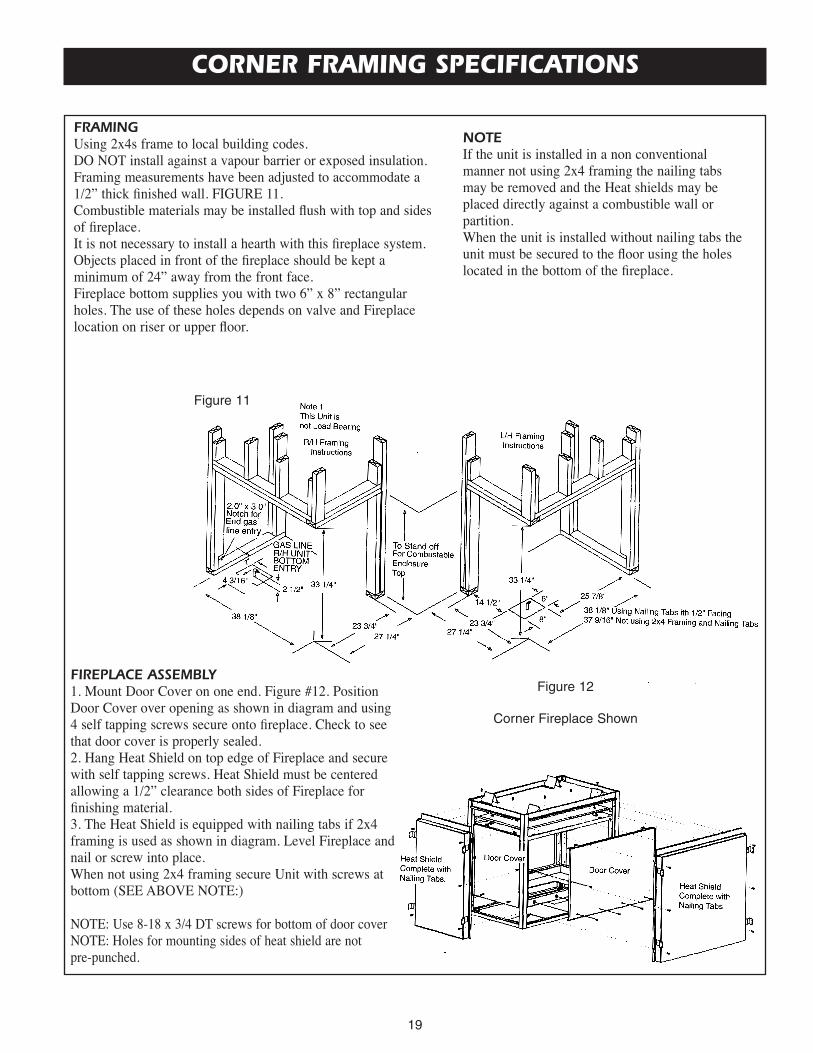
CORNER FRAMING SPECIFICATIONS
FRAMINGUsing 2x4s frame to local building codes.DO NOT install against a vapour barrier or exposed insulation.Framing measurements have been adjusted to accommodate a1/2” thick finished wall. FIGURE 11.Combustible materials may be installed flush with top and sidesof fireplace.It is not necessary to install a hearth with this fireplace system.Objects placed in front of the fireplace should be kept aminimum of 24” away from the front face.Fireplace bottom supplies you with two 6” x 8” rectangularholes. The use of these holes depends on valve and Fireplacelocation on riser or upper floor.
NOTEIf the unit is installed in a non conventionalmanner not using 2x4 framing the nailing tabsmay be removed and the Heat shields may beplaced directly against a combustible wall orpartition.When the unit is installed without nailing tabs theunit must be secured to the floor using the holeslocated in the bottom of the fireplace.
FIREPLACE ASSEMBLY1. Mount Door Cover on one end. Figure #12. PositionDoor Cover over opening as shown in diagram and using4 self tapping screws secure onto fireplace. Check to seethat door cover is properly sealed.2. Hang Heat Shield on top edge of Fireplace and securewith self tapping screws. Heat Shield must be centeredallowing a 1/2” clearance both sides of Fireplace forfinishing material.3. The Heat Shield is equipped with nailing tabs if 2x4framing is used as shown in diagram. Level Fireplace andnail or screw into place.When not using 2x4 framing secure Unit with screws atbottom (SEE ABOVE NOTE:)
NOTE: Use 8-18 x 3/4 DT screws for bottom of door coverNOTE: Holes for mounting sides of heat shield are not pre-punched.
Figure 12
Corner Fireplace Shown
Figure 11

20
UNIVERSAL FIREBOXThe MVF40 is approved as a Zero Clearance Universal Firebox, when using as a Universal Firebox the bottom burner panmust be used. (Part # 38VF-134).
When installing another manufacturer’s log and burner system, follow the manufacturer’s assembly instructions.
For framing, see pages 12 through 18 depending on type of installation. (eg. SEE THRU, ISLAND, PENINSULA, CORNER,AND BAY PENINSULA) Follow all clearances to combustibles in this manual and see below for installation of the BottomFirebox Pan (Part # 38VF-134) that must be used.
The Firebox canopy must not be replaced with a canopy which may be provided with the decorative type unvented room heater.
USE ONLY KINGSMAN DECORATIVE COMPONENT AND REPLACEMENT PARTS.
Figure 13
Warning: Fireplace screen must be closedwhile appliance is in operation.

21
AIR FOR COMBUSTION AND VENTILATION
Today’s homes are built more energy efficient than ever. New materials, increased insulation, and new construction methodshelp reduce heat loss in homes. Home owners weather strip and caulk around windows and doors to keep the cold air outand the warm air in. During heating months, home owners want their homes as airtight as possible.
While it is good to make your home energy efficient, your home needs to breathe. Fresh air must enteryour home. All fuel-burning appliances need fresh air forproper combustion and ventilation.
Exhaust fans, fireboxes, clothes dryers, and fuel burningappliances draw air from the house to operate. You mustprovide adequate fresh air for these appliances. This willinsure proper venting of vented fuel-burning appliances.
PROVIDING ADEQUATE VENTILATIONThe following are excerpts from National Fuel Gas Code. NFPA 54/ANSI Z223.1, Section 5.3, Air for Combustion andVentilation:
All spaces in homes fall into one of the three following ventilation classifications:1. Unusually Tight Construction, 2. Unconfined Space, 3. Confined Space.
The information on pages 20 through 24 will help you classify your space and provide adequate ventilation.
Unusually Tight ConstructionThe air that leaks around doors and windows may provide enough fresh air for combustion and ventilation. However, inbuilding of usually tight construction, you must provide additional fresh air.
Unusually tight construction is defined as construction where:a. walls and ceilings exposed to the outside atmosphere have a continuous water vapor retarder with a rating of one
perm (6 x 10-11 per pasec-m2) or less with openings gasketed or sealed andb. weather stripping has been added on openable windows and doors andc. caulking or sealants are applied to areas such as joints around window and door frames, between sole plates and
floors, between wall-ceiling joints, between wall panels, at penetrations for plumbing, electrical, and gas lines, andat other openings.
If your home meets any of the three criteria above, you must provide additional fresh air. See Ventilation Air From Outdoors, page 24.
Confined and Unconfined SpaceThe National Fuel Gas Code (ANSI Z223.1, 1992 SEction 5.3) defines a confined space as a space whose volume is less than50 cubic feet per 1,000 btu per hour (4.8 m3 per kw) of the aggregate input rating of all appliances installed in that space.Rooms communicating directly with the space in which the appliances are installed*, through openings not furnished withdoors, are considered a part of the unconfined space.
*Adjoining rooms are communicating only if there are doorless passageways or ventilation grills between them.
DETERMINING AIR FLOW FOR FIREBOX LOCATIONDetermining if You Have a Confined or Unconfined SpaceUse the work sheet on the next page to determine if you have a confined or unconfined space.
Space: Includes the room in which you will install firebox plus any adjoining rooms with doorless passageways or ventilation grills between the rooms.
WARNINGThis firebox shall not be installed in a confined spaceunless provisions are provided for adequate combustionand ventilation air. Read the following instructions toinsure proper fresh air for this and other fuel-burningappliances in your home.

22
AIR FOR COMBUSTION AND VENTILATION Cont.
1. Determine the volume of the space (length x width x height).
Length x Width x Height = ______________ cu. ft. (volume of space)
Example: Space size 22ft. (length) x 18 ft. (width) x 8 ft. (ceiling height) = 3168 cu. ft. (volume of space)
If additional ventilation to adjoining room is supplied with grills or openings, add the volume of these rooms to the total
volume of the space.
2. Divide the space volume by 50 cubic feet to determine the maximum Btu/Hr the space can support.
______________ (volume of space) ÷ 50 cu. ft. = 63.3 or 63,300 (maximum Btu/Hr the space can support)
3. Add the Btu/Hr of all fuel burning appliances in the space.
Vent-free firebox __________________ Btu/Hr
Gas water heater* __________________ Btu/Hr
Gas furnace __________________ Btu/Hr
Vented gas heater __________________ Btu/Hr
Gas firebox logs __________________ Btu/Hr
Other gas appliances* + __________________ Btu/Hr
Total = __________________ Btu/Hr
Example: Gas water heater 40,000 Btu/Hr
Vent-free firebox with log heater + 39,000 Btu/Hr
Total = 79,000Btu/Hr
* Do not include direct-vent gas appliances. Direct-vent draws combustion air from the outdoors and vents to the
outdoors.
4. Compare the maximum Btu/Hr the space can support with the actual amount of Btu/Hr used.
__________________ Btu/Hr (maximum the space can support)
__________________ Btu/Hr (actual amount of Btu/Hr used)
Example: 63,300 Btu/Hr (maximum the space can support)
79,000 Btu/Hr (actual amount of Btu/Hr used)
The space in the above example is a confined space because the actual Btu/Hr used is more than the maximum Btu/Hr the
space can support. You must provide additional fresh air. Your options are a follows:
A. Rework work sheet, adding the space of an adjoining room. If the extra space provides an unconfined space, remove
door to adjoining room or add ventilation grills between rooms, See Ventilation Air from Inside Building, page 22.
B. Vent room directly to the outdoors. See ventilation Air
from Outdoors, page 23.
C. Install a lower Btu/Hr firebox, if lower Btu/Hr size
makes room unconfined.
If the actual Btu/Hr used is less than the maximum Btu/Hr
the space can support, the space is an unconfined fined
space. You will need no additional fresh air ventilation.
WARNINGIf the area in which the firebox and gas log heater may beoperated is smaller than that defined as an unconfinedspace, provide adequate combustion and ventilation air byone of the methods described in the National Fuel GasCode, ANSI Z223.1, 1992, Section 5.3.

23
AIR FOR COMBUSTION AND VENTILATION Cont.
VENTILATION AIR FROM INSIDE BUILDINGThis fresh air would come from an adjoining unconfined space. When ventilating to an adjoining unconfined space, youmust provide two permanent openings: one within 12” of the ceiling and one within 12” of the floor on the wall connectingthe two spaces. You can also remove doors into adjoiningrooms. Follow the National Fuel Gas Code NFPA 54/ANSIZ223.1, Section 5.3, Air for Combustion and Ventilation forrequired size of ventilation for required size of ventilationgrills or ducts.
WARNINGRework worksheet, adding the space of the adjoiningunconfined space. The combined spaces must haveenough fresh air to supply all appliances in both spaces.
Ventilation Grills intoadjoining roomOption 1
Ventilation Grillsinto adjoining roomOption 2
Remove Door intoadjoining room
Figure 14

24
AIR FOR COMBUSTION AND VENTILATION Cont.
Ventilation Air From OutdoorsProvide extra fresh air by using ventilation grills or ducts. You must provide two permanent openings: one within 12” of theceiling and one within 12” of the floor. Connect these items directly to the outdoors or spaces open to the outdoors. Thesespaces include attics and crawl spaces.
IMPORTANT: Do not provide openings for inlet or outlet air into attic if attic has a thermostat-controlled power vent.Heated air entering the attic will activate the power vent.
FIGURE 15 - Ventilation Air from Outdoors

25
INSTALLING – Gas Line
INSTALLING GAS LINEEarly signs of carbon monoxide poisoning resemble the flu, withheadaches, dizziness, and / or nausea. If you have these signs, theheater may not be working properly. Get fresh air at once! Turn offgas appliance. Have appliance serviced. Some people (such aspregnant women, persons with heart or lung disease, persons withanemia and those at high altitudes) are more affected by carbonmonoxide than others. Make certain you read and understand allwarnings.Place Burner Base or Grate Assembly in center of fireboxand connect flexible gas line to incoming black iron pipe gas line.
Do not connect appliance before pressure testing gas piping.Damage to gas valve may result and an unsafe condition may becaused.
Prepare incoming black iron gas line with Teflon tape or pipe jointcompound (check with local codes about the use of Teflon tape).Compounds used on threaded joints of gas piping shall be resistantto the action of Liquefied Petroleum (LP or Propane) and should be applied lightly to ensure excess sealant does not enter the gas line.
Complete your gas installation by connecting incoming gas line to regulator. Secure all joints tightly with wrench but do not over-tighten. If a flexible gas line is used, take care not to kink connector. The burner pressure is controlled by the regulator. Check pressureat the pressure test point, which is located on the side of the gas control near the pilot outlet. Make sure that the pressure tap iscompletely closed after checking gas pressure. The pressure should be checked with the appliance burning and the control set on high.
IMPORTANT: Loosen the pipe adapter on the flex tube before installing to the system piping.
CHECK GAS TYPE: The gas supply must be the same as stated on the heater’s rating plate. If the gas supply is different, Do NotInstall the heater. Contact your dealer for the correct model.
For the state of Massachusetts a T-handle gas shut-off valve mustbe used on a gas appliance. This T-handle gas shut-off valve mustbe listed and approved by the state of Massachusetts. This is inreference to the state of Massachusetts state code CMR238.
CAUTION
All gas piping and connections must be tested for leaksafter installation is completed. To test, turn gas valve on,then apply a soap and water solution to all connectionsand joints. If bubbles appear, leak can be detected andcorrected. Never use an open flame for leak testing.Never operate any appliance if a leak is detected!
CAUTIONAny safety screen or guard removed for servicing anappliance must be replaced prior to operating the heater.
FIGURE 16, 16a – Installing gas line and manual shutoff valve
FIGURE 16a – This is one option for installing shutoffvalve. Check local codes for shutoff location regulations.
NOTICE
A qualified gas appliance installer must connect thefireplace to the gas supply. Consult all local codes.

26
FIGURE 18 – Manual and Millivolt Pilot Flames
FIGURE 19 – Millivolt Models
1. Remove the Universal Bottom before installing Kingsman Multiview Burner system by removing 4 screws.2. Position burner assembly as per unit configuration (eg. left corner, right corner, peninsula, etc.)3. Tilt burner assembly so valve is at an angle to the fireplace and lower into position.4. Line the 4 holes on the burner assembly as shown on the diagram with the 4 holes on the fireplace and screw into place
with 1/2” DT Screws.5. Install log support plates as shown in the lower diagram. (Make sure the log support plate with the cut out is placed on
the side where the ODS Pilot is located.)
NOTE: When installing Burner assembly into a corner installation it is very important that the NON FLAME END of theburner assembly is facing the side of the enclosure that is built in.
FIREBOX BOTTOM ODS PILOT LOCATION
NON FLAME ENDOF BURNERASSEMBLY(SEE NOTE)
BURNERINSTALLATIONHOLES Figure 17
UNIVERSALBOTTOM
NOTE: LOG LOCATORPIN ORIENTATION
INSTALLING – MVFB4040 Burner SystemsWarning: Failure to position parts in accordance with these diagrams or failure to use only part specifically
approved with this heater may result in property damages or personal injury.
CLEANING AND SERVICING OFBURNER / ODS PILOTIt is recommended to annually inspect and clean the unit toprevent malfunction and / or sooting. This operation shouldbe performed by your dealer or a qualified technician.
1. Remove fireplace hood and screen. (Refer to Installationof Door Screen and Hood, page 30.)
2. Remove log set, handling carefully by holding gently ateach end. (Refer to Log Placement, page 26.) Gloves arerecommended to prevent skin irritation from ceramic.
Annual Cleaning / Inspection• Do not use cleaning fluids to clean logs or any part of the
heater.• Use a soft bristle brush or a vacuum with brush attachment.• Vacuum loose particles and dust from burner ports, valve
and blower compartments.• Vacuum any accumulation of lint from primary mixing
tube.• Inspect ODS pilot for operation, accumulation of lint at the
air inlet holes.• Verify flame pattern and log placement for proper
operation.• Verify that all ports ignite and cross over smoothly from rear
to front burner.
WARNINGTurn off heater and allow to cool before cleaning. Only aqualified service technician should service and repair appliance.Failure to keep primary air openings clear, may result insooting and property damage.

27
INSTALLING – MVFB4040 Burner Systems and LOGF38
WARNINGThe positioning of the logs is critical for the safe and clean operation of this heater. Sooting and otherproblems can occur if the logs are not properly andfirmly positioned in the heater. Never add additionallogs or embellishments such as pine cones, vermiculite,volcanic rock or rock wool to the heater.
Log InstallationThe Kingsman log set has been numbered for ease of installation.1. Place log #1 onto plate with the ODS Pilot extending throughthe notch area. Position holes on under side of Log #1 with the 2vertical tabs on the plate and lower onto plate.2. Place log #4 onto plate opposite of plate with the ODS Pilot3. Position Log #5 onto end Pin of Log #4 as shown in diagram4. Position Log #3 onto center Pin of Log #4 as shown in diagram.5. Position log #2 onto Pin of Log #1 and position Log #2 upagainst Log #4.NOTE LOG #5 IS TO BE POSITIONED ON THE NON FLAME SIDE.
Crushed Rock InstallationPlace crushed rock onto firebox bottom making sure not toplace any rock onto the burner or burner ports as this willcause carboning, delayed ignition, and will raise CarbonMonoxide to very dangerous levels.
Side Brick Panel Installation (Long Side)1. Remove side brick clip located on top of Firebox.2. Slide Side Brick Panel into Firebox through the small sideopening and center from left to right and push tight against sidewall of Firebox.3. Place Brick Clip back into position and tighten
Back Brick Panel Installation (Short Side)1. Remove back brick clip located on top of Firebox.2.Slide Back Brick Panel into Firebox through the large sideopening and center form left to right and push tight against sidewall of Firebox.3. Place Brick Clip Back into position and tighten.
Optional Back and Side Brick Panel Installations
NOTE: BRICK CLIPS CAN BE REPOSITIONED DEPENDING ON TYPE OF INSTALLATION
Figure 21
Figure 20

28
Log Tabs
Step (1) If using the MVF40 chassis, omit this step (go to step2). If using MDV30 or MDV38, break glowing embers intothumbnail size and place along the perimeter of the burner.Do not place on middle burner (as illustrated). Care should betaken not to block burner ports.
Step (2) Take Log #4 and place onto burner using the two logtabs (located on burner pan) as a guide.
Log Pin
Log Pin
Step (3) Take Log #1 and place onto burner using the two logtabs (located on burner pan) as a guide.
LOGF38 PLACEMENT FOR MVFB4040 BURNER SYSTEM

29
Step (4) Place Log #5 onto Log #4 using the log pin as aguide. Ensure Log #5 rests on the shape of Log #4.
Log Pin
Step (5) Place Log #3 onto both Log #1 and Log #5 using thelog pins as a guide.
Log Pin
Step (6) Place Log #2 onto both Log #1 and #4 using the logpins as a guide. Ensure Log #2 does not cover burner.
LOGF38 PLACEMENT FOR MVFB4040 BURNER SYSTEM

30
INSTALLING – GLMVF40 Burner System
1. Install Optional Brick Liners before installing GLVF40 Burner system.2. Remove the Universal Burner Bottom before installing Kingsman Multiview Burner system by removing 4 screws.3. Position burner assembly as per unit configuration. Front of Gas Valve should always be accessible after installation.4. Tilt burner assembly so valve is at an angle to the Fireplace and lower into position.5. Center Burner assembly inside Fireplace and fasten with 2 supplied screws. 6. Place 8 Grate Bars into Burner System by sliding them into square openings.
NOTE: After installation of Burner, make sure Log support plates are still in their proper position.
Warning: Failure to position parts in accordance with these diagrams or failure to use only part specificallyapproved with this heater may result in property damages or personal injury.

31
LOGC31 PLACEMENT for GLMVF40 BURNER GRATE
Step (1) Place notched area of Log #1 against the O.D.S.Pilot as shown. Place Log31C-A and Log31C-B along thegrate bar as shown.
Step (2) Place flat area of Log #2 against Tab 2 and over topof Log #1. Locate log mounting hole on Log #3. Position holeon Tab 3 as shown. Do not place log over the center burnertube.
Step (3) Locate the 2 mounting holes on the bottom of Log #4and position them onto Tabs 4A and 4B. Place V area of Log#5 on the grate bar and then rest Log #5 on the flat area ofLog #2.
Step (4) Place the flat area of Log #6 on the burner pan. Leanagainst Logs #4 and #5. Locate flat notched areas of Log #2and Log #3. Place Log #7 onto these with charred branch inthe down position.

32
Step (5) Place ember rocks on ember plates. (Warning: Do not place ember rocks on the burner tubes).
Step (6) Place lava rock on the bottom of the fire boxsurrounding the burner system. Sprinkle vermiculite over topof the Lava Rock.
LOGC31 PLACEMENT for GLMVF40 BURNER GRATE

33
CAUTIONDo not wire 120 Volt power to Millivolt switches orthermostats.
MILLIVOLT LIGHTING INSTRUCTIONS

34
INSTALLING – Screen Door, Shield + HoodHinged grill1. In the bottom inside corner of post thereare Teardrop slots. As shown in Ref: B.2. On the Grill there are screws in bothends. To install, slide the head into one ofthe teardrop slots, then slide Grill toopposite side. These screws may have tobe adjusted for proper alignment, andlength.3. Install 2 springs on both ends of grill.Refer to Ref: C. for proper installation.
Hinged bottom panel1. Ref:E Install two 8-32 x 1/2” screws andnuts, from the inside of panel with nut tothe outside. Tighten one side only.2. Thread of loose screw should notprotrude past face of nut.3. The end of the panel, with tightenedscrew can now be slid into teardrop holeRef: B4. Align opposite side of panel withteardrop Ref:B and tighten screw.5. Ref:C for spring installation.
Fixed grill and panel1. In both top and bottom inside corners ofpost there are vertical slots, as shown inRef: A & B2. Grills & panels have tabs on both ends.To install slide the tabs into slots on oneside of post, top side up (Ref:D)3. Clip opposite side of flat panel intoopposite post. Extra force may be requiredto push grill or panel over to clip it in.Repeat for other fixed grills and panels.
Curtain & Hood Installation
Curtain:1. Slide curtain onto rods.2. Slide round end of rod into side post Ref:BUsing two 1/2” DT screws, mount flattenedend of rod to the bottom side of rod hangerbrackets Ref:A, Repeat this step for oppositeside.3. Mount curtain rod on short side offireplace Ref: C. Insert one end into slot onthe inside of post, slide it all the way in, thenslide back to insert into other side of post.
Hood1. Ref:D Loosen pre-installed 1/2” DT screwswith 1/4” wrench. Slide slotted area of hoodunder screws.2. Tighten screws to finish installation, repeatthis step for all hoods if applicable.
Figure 23
Figure 24
Warning: Fireplace screenmust be closed whileappliance is in operation.

35
INSTALLING – Fan Kit
WARNINGElectrical Grounding Instruction - Thisappliance is equipped with a three -pronged (grounding) plug for yourprotection against shock hazard andshould be plugged directly into aproperly grounded three-prongreceptacle.
WARNINGA qualified electrician must connectelectrical wiring to junction outlet forbuilt-in installation. Follow all codes.
WARNINGLabel all wires prior to disconnectionwhen servicing controls. Wiring errorscan cause improper and dangerousoperation. Verify proper operation andservicing.
Installation of Optional Fan KitUse Part number Z36FK fan assembly. NOTE thatthe thermodisc will not be used, bypass these twowires by stripping the ends and tie together with amarrette (as shown Fig. 27).
Fan Installation1. To install fan locate #8 screws in bottom of fireplace Ref A. Fan and fan shield should always be mounted at the end ofthe fireplace with the small clearance shield mounted (corner kit peninsula kit & see-through kit)2. Slide teardrop hole on fan housing over the two #8 screws, slide fan away from screws and release.
Fan Shield installation1. Slide shield under firebox nearest fan.2. Install two 1/2” DT screws from inside of firebox into fan shield.3. If fireplace has been installed with fan shield mounted opposite to the side with clearance shield. It must be removed andinstalled on the appropriate side.
Fan shield location* Caution: Fan shield must be mounteddirectly in front of fan.
AlternateFan & Shieldlocation
Suggested Location for 120VJunction Box for Fan Kit
Suggested Location for 120VPower Cable
Fan Shield
Clearance Shield
Fan
Ref: A
Ref: A
Optional in unitvariable speedcontrol location
WALL MOUNTEDVARIABLE SPEEDCONTROL
Figure 25
Figure 26
Figure 27
36
ILLUSTRATED PARTS LIST
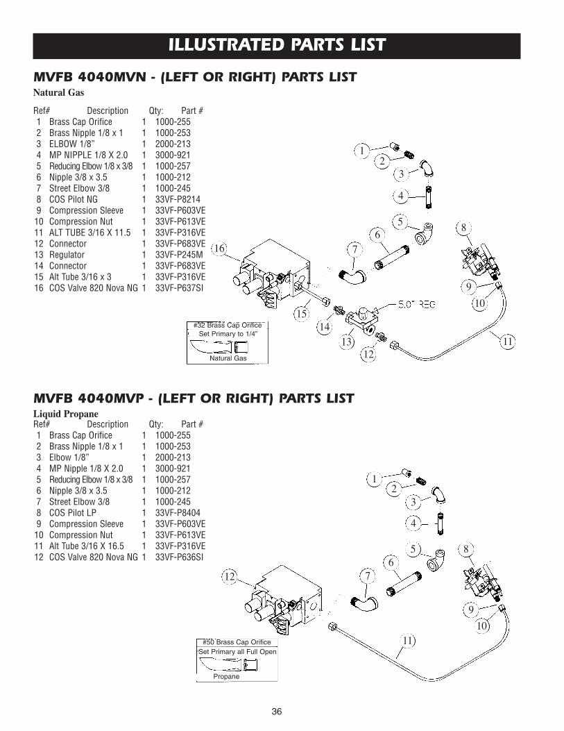
MVFB 4040MVN - (LEFT OR RIGHT) PARTS LISTNatural Gas
MVFB 4040MVP - (LEFT OR RIGHT) PARTS LISTLiquid Propane
Ref# Description Qty: Part #1 Brass Cap Orifice 1 1000-2552 Brass Nipple 1/8 x 1 1 1000-2533 ELBOW 1/8” 1 2000-2134 MP NIPPLE 1/8 X 2.0 1 3000-9215 Reducing Elbow 1/8 x 3/8 1 1000-2576 Nipple 3/8 x 3.5 1 1000-2127 Street Elbow 3/8 1 1000-2458 COS Pilot NG 1 33VF-P82149 Compression Sleeve 1 33VF-P603VE10 Compression Nut 1 33VF-P613VE11 ALT TUBE 3/16 X 11.5 1 33VF-P316VE12 Connector 1 33VF-P683VE13 Regulator 1 33VF-P245M14 Connector 1 33VF-P683VE15 Alt Tube 3/16 x 3 1 33VF-P316VE16 COS Valve 820 Nova NG 1 33VF-P637SI
Ref# Description Qty: Part #1 Brass Cap Orifice 1 1000-2552 Brass Nipple 1/8 x 1 1 1000-2533 Elbow 1/8” 1 2000-2134 MP Nipple 1/8 X 2.0 1 3000-9215 Reducing Elbow 1/8 x 3/8 1 1000-2576 Nipple 3/8 x 3.5 1 1000-2127 Street Elbow 3/8 1 1000-2458 COS Pilot LP 1 33VF-P84049 Compression Sleeve 1 33VF-P603VE10 Compression Nut 1 33VF-P613VE11 Alt Tube 3/16 X 16.5 1 33VF-P316VE12 COS Valve 820 Nova NG 1 33VF-P636SI
1
16
1514
1312
11
10
7
4
85
2
9
6
3
1
12
1110
7
4
85
2
9
6
3
#32 Brass Cap OrificeSet Primary to 1/4”
Natural Gas
#50 Brass Cap OrificeSet Primary all Full Open
Propane

37
ILLUSTRATED PARTS LIST Cont.
MVF 40 BURNER ASSEMBLY
28
27
26
29 30
25
24
23
22
21
20
1918
1716
1514
1312
1110
7
485
2
9
6
31
Ref# Description Qty: Part #1 Brass Cap Orifice 1 1000-2552 Brass Nipple 1/8 x 1 1 1000-2533 ELBOW 1/8” 1 2000-2134 MP NIPPLE 1/8 X 2.0 1 3000-9215 Reducing Elbow 1/8 x 3/8 1 1000-2576 Nipple 3/8 x 3.5 1 1000-2127 Street Elbow 3/8 1 1000-2458 COS Pilot NG 1 33VF-P82149 Compression Sleeve 1 33VF-P603VE10 Compression Nut 1 33VF-P613VE11 ALT TUBE 3/16 X 11.5 1 33VF-P316VE12 Connector 1 33VF-P683VE13 Regulator 1 33VF-P245M14 Connector 1 33VF-P683VE15 Alt Tube 3/16 x 3 1 33VF-P316VE16 COS Valve 820 Nova NG 1 33VF-P637SI17 Piezo 1 1000-21418 Valve Bkt 1 38VF-11219 Pan Bottom 1 38VF-10420 Burner Bkt 4 38VF-10521 ODS Bracket 1 38VF-10622 Burner ASSy 1 N/A23 Log Holder (LH) 1 38VF-11324 Log Holder (RH) 1 38VF-11425 Grate Assembly 1 N/A26 Log #527 Log #428 Log#229 Log #130 Log #3
Natural Gas System Shown

38
GLMVF40 ILLUSTRATED PARTS LIST
24
20
1615
14
13
5
5
453
2
19
6
1
12
910
11
13
1415
1617
1817 16
21
2223
1718
1716
2322
21
19
24
20 19
8
7
Enlarged View
ITEM NO. QTY. PART NO. (NG) PART NO. (LP) DESCRIPTION1 1 40GL-PAN 40GL-PAN Burner Pan2 1 40GL-BRN 40GL-BRN Burner Assembly3 4 4200-132 4200-132 Burner Hold Down4 1 39GL-107 39GL-107 ODS Log Support Plate5 3 39GL-117 39GL-117 Log Support Plate6 1 39GL-108 39GL-108 ODS Pilot Burner7 1 39GL-104 39GL-104 Orifice Bracket8 1 39GL-112 39GL-112 Base Cover9 1 39GL-102 39GL-102 Control Panel10 1 1000-216 1000-216 Rocker Switch11a 1 1000-214 1000-214 Piezo igniter11b 1 1000-215 1000-215 Pal Nut for Piezo igniter12 8 39GL-105 39GL-105 Grate Bar13 1 350-P217SI 350-P217SI 1 1/2” On/Off Extension Knob14 1 350-P218SI 350-P218SI 1 1/2” Hi/Lo Extension Knob15 1 33VF-P637SI 33VF-P636SI Vent free Gas Valve16 1 33VF-P316VE 33VF-P316VE Alt Tubing 3/16”17 2 33VF-P683VE Connector (Natural Gas Only)18 1 33VF-P245M Regulator (Natural Gas Only)19 1 33VF-P8214 33VF-p8404 ODS Pilot System20 1 4000-P963VE 4000-P963VE 3/8 Make x 3/8 Flare Adapter21 1 350-P3875D 350-P3875D 10” - 3/8 Flex Connector22 1 3100-466PA 3100-466PA 3/8 Flare x 1/8 Fipt Adapter23 1 1000-253 1000-253 1/8 Closed Nipple24 1 1000-255 (#32) 1000-255 (#49) Orifice

39
ACCESSORY AND PARTS LIST
Product No. Description
MVF40 KINGSMAN MULTI-SIDED VENT FREE FIREPLACE:Listed for USA as a Universal Firebox
Choose your View: (Required for each unit)MVF40CK Corner Kit - One Large Side Open, One Small Side OpenMVF40SK See-Through Kit - Two Large Sides OpenMVF40PK Peninsula Kit - Two Large Sides Open, One Small Side OpenMVF40BK Bay Peninsula Kit - One Large Side Open, Two Small Sides OpenMVF40IK Island Kit - Four Sides Open
Choose Grill Kits or Panel Kits: (Required for View Chosen Above)MGCKBP Grill Kit Corner - Classic Polish Brass (Two Sets)MGCKBA Grill Kit Corner - Classic Antique Brass - (Two Sets)MGCKBC Grill Kit Corner - Classic Chrome (Two Sets)MGCKBL Grill Kit Corner - Black (Two Sets)MGCKPB Grill Kit Corner - Polish Brass (Two Sets)MGCKAB Grill Kit Corner - Antique Brass (Two Sets)MGCKCR Grill Kit Corner - Chrome (Two Sets)MVF40PCK Panel Kit for Corner Kit - Black (Two Sets)
MGSKBP Grill Kit See-Through - Classic Polish Brass (Two Sets)MGSKBA Grill Kit See-Through - Classic Antique Brass (Two Sets)MGSKBC Grill Kit See-Through - Classic Chrome (Two Sets)MGSKBL Grill Kit See-Through - Black (Two Sets)MGSKPB Grill Kit See-Through - Polish Brass (Two Sets)MGSKAB Grill Kit See-Through - Antique Brass (Two Sets)MGSKCR Grill Kit See-Through - Chrome (Two Sets)MVF40PSK Panel Kit See-Through - Black (Two Sets)
MGPKBP Grill Kit Peninsula - Classic Polish Brass (Three Sets)MGPKBA Grill Kit Peninsula - Classic Antique Brass (Three Sets)MGPKBC Grill Kit Peninsula - Classic Chrome (Three Sets)MGPKBL Grill Kit Peninsula - Black (Three Sets)MGPKPB Grill Kit Peninsula - Polish Brass (Three Sets)MGPKAB Grill Kit Peninsula - Antique Brass (Three Sets)MGPKCR Grill Kit Peninsula - Chrome (Three Sets)MVF40PPK Panel Kit Peninsula - Black (Three Sets)
BURNER SYSTEM & LOG SET (REQUIRED FOR MVF40 FIREBOX)
OPTION 1GLMVF40MVN Vent Free Multiview Burner System – Millivolt Valve 38,000 BTU/HR Natural GasGLMVF40MVP Vent Free Multiview Burner System – Millivolt Valve 30,500 BTU/HR Liquid PropaneLOGC31 Log Set LOGC31 required for GLMVF40 Burner System
OPTION 2MVFBR4040MVN Vent Free Right Burner System – Millivolt Valve 38,000 Natural GasMVFBR4040MVP Vent Free Right Burner System – Millivolt Valve 34,000 Liquid Propane
MVFBL4040MVN Vent Free Left Burner System – Millivolt Valve 38,000 BTU/HR Natural GasMVFBL4040MVP Vent Free Left Burner System – Millivolt Valve 34,000 BTU/HR Liquid PropaneLOGF38 Log Set required for MVFB40 R/L Burner System

40
ACCESSORY AND PARTS LIST (CONT.)
MGBKBP Grill Kit Bay Peninsula - Classic Polish Brass (Three Sets)MGBKBA Grill Kit Bay Peninsula - Classic Antique Brass (Three Sets)MGBKBC Grill Kit Bay Peninsula - Classic Chrome (Three Sets)MGBKBL Grill Kit Bay Peninsula - Black (Three Sets)MGBKPB Grill Kit Bay Peninsula - Polish Brass (Three Sets)MGBKAB Grill Kit Bay Peninsula - Antique Brass (Three Sets)MGBKCR Grill Kit Bay Peninsula - Chrome (Three Sets)MVF40PBK Panel Kit Bay Peninsula Kit - Black (Three Sets)
MGIKBP Grill Kit Island - Classic Polish Brass (Four Sets)MGIKBA Grill Kit Island - Classic Antique Brass (Four Sets)MGIKBC Grill Kit Island - Classic Chrome (Four Sets)MGIKBL Grill Kit Island - Black (Four Sets)MGIKPB Grill Kit Island - Polish Brass (Four Sets)MGIKAB Grill Kit Island - Antique Brass (Four Sets)MGIKCR Grill Kit Island - Chrome (Four Sets)MVF40PIK Panel Kit Island Kit - Black (Four Sets)
ACCESSORIES OPTIONALZ36SAB Surround - Antique Brass (Coverage Old Style 33 3/4” H x 39 7/8” W)Z36SCR Surround - Chrome (Coverage New Style 34 1/2” H x 41 1/8” W)Z36SPB Surround - Polish Brass (Coverage New Style 34 1/2” H x 41 1/8” W)Z36SLAB Surround Slim Line - Antique Brass (Coverage 34 1/4” H x 37 1/2” W)Z36SLCR Surround Slim Line - Chrome (Coverage 34 1/4” H x 37 1/2” W)Z36SLPB Surround Slim Line -Polish Brass (Coverage 34 1/4” H x 37 1/2” W)Z36SLBL Surround Slim Line - Gun Metal Black (Coverage 34 1/4” H x 37 1/2” W
ZVF36DS Door Frame - c/w Fixed ScreenZVF40SDS Door Frame Small - c/w Fixed Screen
Z36FK Fan Kit w/Variable Speed Wall Mount Control (Temperature Sensing)Z1MT Thermostat Millivolt Wall MountZ80PT Thermostat Programmable Digital Millivolt Wall Mount (1F80-40)Z1RC Remote Control Millivolt (On/Off with LED) (Model I)ZART Remote Control Thermostat Millivolt (Model K)RMCBN Remote Control - Basic - Natural Gas (On/Off, Hi/Lo Flame Adjustment, Millivolt Only)RMCBP Remote Control - Basic - Liquid Propane (On/Off, Hi/Lo Flame Adjustment, Millivolt Only)DCHS Remote Control Heatshield

41
TROUBLESHOOTING
NOTE: all troubleshooting items are listed in order ofoperation.
When igniter button is pressed, there is no spark at ODS/Pilot.Possible Cause Remedy1. igniter electrode positioned wrong. 1. Replace igniter.2. igniter electrode is broken. 2. Replace igniter.3. igniter electrode not connected to igniter cable. 3. Reconnect igniter cable.4. igniter cable pinched or wet. 4. Free igniter cable if pinched by any metal or tubing.
Keep igniter cable dry.5. Piezo-igniter nut is loose. 5. Tighten nut.6. Broken igniter cable. 6. Replace igniter cable.7. Bad piezo-igniter. 7. Replace piezo-igniter.
Appliance produces unwanted odors.Possible Cause Remedy1. Appliance burning vapors from paint, hair spray, 1. Ventilate room. Stop using odor-causing products
glues, etc. while heater is running2. Gas leak. 2. Locate and correct all leaks.
Appliance shuts off in use.Possible Cause Remedy1. Not enough fresh air is available for ODS/pilot 1. Open window and/or door ventilation.
to operate.2. Low line pressure. 2. Contact local gas company.3. ODS/pilot is partially clogged. 3. Clean ODS/pilot.
Gas odor even when control knob is in OFF position.Possible Cause Remedy1. Gas leak. 1. Locate and correct all leaks.2. Control valve defective. 2. Replace control valve.
When igniter button is pressed, there is a spark at ODS/pilot, but no ignition.Possible Cause Remedy1. Gas supply turned off or manual shutoff valve closed. 1. Turn on gas supply or open manual shutoff valve.2. Control knob not in PILOT position. 2. Turn control knob while in PILOT position.3. Control knob not pressed in while in PILOT position. 3. Press control knob in while in PILOT position.4. Air in gas lines when installed. 4. Continue holding down control knob. Repeat igniting
operation until air is removed.5. ODS/pilot is clogged. 5. Replace ODS/pilot assembly or get it serviced.6. Gas regulator setting is not correct. 6. Replace gas regulator.
ODS/pilot lights, but flame goes out when control knob is released.Possible Cause Remedy1. Control knob not fully pressed in. 1. Press control knob in fully.2. Control knob not pressed in long enough. 2. After ODS/pilot lights, keep control knob pressed in
for 30 seconds.3. Manual shutoff valve not fully open. 3. Fully open manual shutoff valve.4. Thermocouple connection loose at valve. 4. Hand tighten until snug, then tighten 1⁄4 turn more.
WARNINGTurn off and let cool before servicing. Only a qualifiedservice person should service and repair heater.

42
TROUBLESHOOTING Cont.
5. Pilot flame not touching thermocouple, which allows 5. Contact local gas company.thermocouple to cool, causing pilot flame to go out.Problem could be caused by one or both of the following:A) Low gas pressureB) Dirty or partially clogged ODS/pilot.
6. Thermocouple damaged. 6. Replace thermocouple7. Control valve damaged. 7. Replace control valve.
One or both burners do not light after ODS/pilot is lit.Possible Cause Remedy1. Burner orifice is clogged. 1. Clean burner or replace light burner orifice.2. Inlet pressure is too low. 2. Contact qualified service person.
Delayed ignition of burner.Possible Cause Remedy1. Manifold pressure is too low. 1. Contact local gas company.2. Burner orifice is clogged. 2. Clean burner or replace burner orifice.
Burner backfiring during combustion.Possible Cause Remedy1. Burner orifice is clogged or damaged. 1. Clean burner or replace burner orifice.2. Burner is damaged. 2. Replace burner.3. Gas regulator is defective. 3. Replace Gas regulator.
Slight smoke or odor during initial operation.Possible Cause Remedy1. Vapors from paint or curing process of logs. 1. Problem will stop after a few hours of operation. Run
the heater with the damper open if you have one or opena window for the first few hours.
Log appears to smoke (after initial operation).Possible Cause Remedy
1. Log heater is intended to be smokeless. Turn off heater and call qualified service person.
Heater produces a whistling noise when burner is lit.Possible Cause Remedy1. Turning control knob to HI position when burner is cold. 1. Turn control knob to LO position and let warm up for a
minute2. Air in gas line. 2. Operate burner until air is removed from line. Have gas
line checked by local gas company.3. Dirty or partially clogged burner orifice. 3. Clean burner or replace burner orifice.
No Gas to pilot.Possible Cause Remedy1. LP regulator shut down due to inlet pressure being 1. Verify LP tank regulator is installed and set at 11 to 13
too high inches w.c.2. Replace LP regulator on heater.

43
BASIC ONE YEAR WARRANTYDuring the first year after installation, we will provide a replacement for any component part of your unit found to be defective in materials or workmanship, including labour costs. Repair work requires prior approval by Kingsman, labour costs are based on a predetermined rateschedule and any repair work must be done through an authorized Kingsman dealer.
LIMITED LIFETIME WARRANTYThe heat exchanger, combustion chamber and burner of every Kingsman product excluding the Outdoor Firepit are warranted against materials or workmanship during the period the product is owned by the original owner. The part to be replaced must be returned to our distributor in exchange for the replacement part. Any labor, material, freight and/or handling charges associated with any repair or replacement pursuant to this Limited Lifetime Warranty will not be covered by this warranty.
GENERAL TERMSIn lieu of providing a replacement part, we may, at our option, provide the distributor's component purchase price from us or a credit equal to the distributors component purchase price from us toward the purchase of any new unit which we distribute. If a credit is given in lieu of a replacement part, the rating plate from the unit being replaced must be submitted on a warranty claim, and the unit beingreplaced must be made available to our distributor for disposition.
In establishing the date of installation for any purpose, including determination of the starting date for the term of this Limited Lifetime Warranty,reasonable proof of the original installation date must be presented*, otherwise the effective date will be based upon the date of manufactureplus thirty (30) days.
We will not be responsible for and you, the user, will pay for: (a) damages caused by accident, abuse, negligence, misuse, riot, fire, flood,or Acts of God (b) damages caused by operating the unit where there is a corrosive atmosphere containing chlorine, fluorine, or any other damaging chemicals (other than in a normal residential environment) (c) damages caused by any unauthorized alteration or repair of the unit affecting its stability or performance (d) damages caused by improper matching or application of the unit or the unit's components(e) damages caused by failing to provide proper maintenance and service to the unit (f) any expenses incurred for erecting, disconnecting or dismantling the unit (g) parts or supplies used in connection with service or maintenance (h) damage repairs, inoperation or inefficiencyresulting from faulty installation or application (i) electricity or fuel costs or any increase in electricity or fuel cost whatsoever including additional or unusual use of supplemental electric heat.
We shall not be liable for any incidental, consequential, or special damages or expenses in connection with any use or failure of this unit. We have not made and do not make any representation or warranty of fitness for a particular use or purpose, and there is no implied conditionof fitness for a particular use or purpose. We make no express warranties except as stated in this Limited Lifetime Warranty. No one is authorizedto change this Limited Lifetime Warranty or to create for us any other obligation or liability in connections with this unit. Any implied warranties shall last for one year after the original installation. Some states and provinces do not allow the exclusion or limitation of incidental or consequential damages or do not allow limitations on how long an implied warranty or condition lasts, so the above limitations or exclusionsmay not apply to you. The provisions of this limited warranty are in additions to and not a modification of or subtraction from any statutorywarranties and other rights and remedies provided by law.
Save this certificate. It gives you specific legal rights, and you may also have other rights which may vary from state to state and province to province.
In the event your unit needs servicing, contact your dealer or contractor who installed or serviced your unit. When requesting service, please have the model and serial number from each unit readily available. If your dealer needs assistance, the distributor is available for supportand we, in turn support the distributor's efforts.
Fill in the installation date and model and serial numbers of the unit in the space provided below and retain this limited warranty for your files.
Model No. Serial No. Date installed
Dealer or Contractor Name:
*To receive advantage of your warranty, you must retain the original records that can establish the installation date of your unit.
LIMITED LIFETIME WARRANTY
This Limited Lifetime Warranty applies only while the unit remains at the site of the originalinstallation and only if the unit is installed inside the continental United States, Alaska, Hawaii,and Canada. The warranty applies only if the unit is installed and operated in accordance with the printed instructions and in compliance with applicable installation and building codes and good trade practices.
The Ultimate in Design, Engineering & Quality