oxalis: a distrubuted, extensible ophthalmic image annotation...
TRANSCRIPT

OXALIS: A DISTRUBUTED, EXTENSIBLE OPHTHALMIC IMAGE ANNOTATION SYSTEM
by
Daniel Ertman
BS Computer Engineering, University of Pittsburgh
BA English Writing, University of Pittsburgh
Submitted to the Graduate Faculty of
the School of Engineering in partial fulfillment
of the requirements for the degree of
Master of Science
University of Pittsburgh
2003

UNIVERSITY OF PITTSBURGH
SCHOOL OF ENGINEERING
This thesis was presented
by
Daniel Ertman
It was defended on
March 26th, 2003
and approved by
James Thomas Cain, Professor, Electrical Engineering Department
Ivan Kourtev, Assistant Professor, Electrical Engineering Department
Thesis Advisor: Raymond Hoare, Assistant Professor, Electrical Engineering Department
ii
ABSTRACT
OXALIS: A DISTRUBUTED, EXTENSIBLE OPHTHALMIC IMAGE ANNOTATION
SYSTEM
Daniel Ertman
University of Pittsburgh, 2003
Currently, ophthalmic photographers and clinicians write reports detailing the location
and types of disease visible in a patient’s photograph. When colleagues wish to review the
patient’s case file, they must match the report with the image. This is both inefficient and
inaccurate. As a solution to these problems, we present Oxalis, a distributed, extensible image
annotation architecture, implemented in the Java programming language. Oxalis enables a user
to: 1) display a digital image, 2), annotate the image with diagnoses and pathologies using a
freeform drawing tool, 3) group images for comparison, and 4) assign images and groups to
schematic templates for clarity. Images and annotations, as well as other records used by the
system, are stored in a central database where they can be accessed by multiple users
simultaneously, regardless of physical locality. The design of Oxalis enables developers to
modify existing system components or add new ones, such as display capabilities for a new
image format, without editing or recompiling the entire system. System components can elect to
be notified when data records are created, modified, or removed, and can access the most current
system data at any point. While Oxalis was designed for ophthalmic images, it represents a
generic architecture for image annotation applications.
iii

TABLE OF CONTENTS
Page
LIST OF TABLES…………………………………………………………………… vii LIST OF FIGURES………………………………………………………………….. viii 1.0 INTRODUCTION………………………………………………………….. 1 1.1 Problem Statement………………………………………………………. 1 1.2 Currently Used Systems…………………………………………………. 3 1.2.1 Hardware Modules……………………………………………... 3 1.2.2 I2CNet….………………………………………………………. 4 1.2.3 PAIS…….……………………………………………………… 5 1.2.4 Show-and-Tell…………………………………………………. 6 1.2.5 IBMAS…………………………………………………………. 6 1.2.6 EyeScape Imaging Systems……………………………………. 7 1.2.7 Software Development Kits……………………………………. 7 2.0 SYSTEM OVERVIEW………………………………………………………… 9 2.1 High-Level Architecture………………………………………………… 9 2.2 Patient Records………………………………………………………… 10 2.3 Image Upload and Display……………………………………………... 11 2.4 Diagnoses List…………………………………………………………… 14 2.5 Annotations……………………………………………………………… 17 2.6 Image Groups…………………………………………………………….. 20
iv

Page 2.7 Templates………………………………………………………………… 23 3.0 TECHNICAL DETAILS OF ANNOTATION……………………………….. 26 3.1 Initialization……………………………………………………………… 27 3.2 Event Model……………………………………………………………… 31 3.3 Image Panels………………………………………………………..……. 34 3.4 Annotation Panels………………………………………………………... 38 3.5 Diagnoses List and Diagnoses Tree……………………………………… 41 3.6 Export and Data Managers………………………………………………. 49 3.7 Conclusion……………………………………………………………….. 53 4.0 UNTRUSTED ENVIRONMENTS……………………………………………. 54 4.1 Protecting the Users’ Data……………………………………………….. 55 4.1.1 Protecting the Database………………………………………… 55 4.1.2 Protecting the Data Inside Oxalis……………………………… 58 4.2 Protecting Developers’ Intellectual Property……………………………. 61 4.2.1 Brokerage Architecture………………………………………… 62 4.2.2 Object Instantiation……………………………………………. 63 4.2.2.1 The ClassRegistry Object……………………………. 66 4.2.3 Interoperability Interfaces……………………………………… 69 4.2.4 Example………………………………………………………... 69 4.3 Results Of Testing……………………………………………………….. 75 4.4 Conclusion……………………………………………………………….. 75 5.0 CONCLUSION…………………………………………………………………. 76
v

BIBLIOGRAPHY…………………………………………………………………… 78
vi

LIST OF TABLES
Page
Table 1. Example records from the DiagnosesList table.……………………………. 43
vii

LIST OF FIGURES
Page Figure 1. High-level overview of the Oxalis system. ...................................................10 Figure 2. Open Patient Screen. The user is selecting to open John Smith’s record...............................................................................11 Figure 3. Image Upload. The user selects to upload an image file (left), and then chooses the file to upload (right).....................................................12 Figure 4. An Indocyanine Green image displayed by Oxalis. ......................................13 Figure 5. Sequence diagram for creating a patient record, uploading and displaying an image................................................................13 Figure 6. Diagnoses List. This figure shows the diagnoses list in its default configuration (top), and after the user has made a selection (bottom)........................................................................................15 Figure 7. Diagnoses Tree. A user elects to edit the diagnoses list (left) and is presented with the list in tree form (right)...........................................16 Figure 8. Entity-Relationship model of the diagnoses list. ...........................................17 Figure 9. Image Annotation. The user has created an annotation on the image (top left). Note that the annotation color is semi-transparent. Colors are based on the selection in the diagnoses list. The user then moves the annotation into position on the image (top right). Next, the user reshapes the annotation slightly to refine the annotated region (bottom left). Finally, the user activates a context-sensitive menu for the annotation (bottom right)....................................................................18 Figure 10. Sequence diagram for creating an annotation. ............................................19 Figure 11. The user has selected to create a group (left). The user then selects and orders the images, and gives the group a name (right). .....20
viii

Page
Figure 12. Three images within an image group. Note the position of the scrollbar, indicated by arrows. This group was created as an example, and may or may not represent three images from the same patient.............................................................................................................22 Figure 13. Sequence diagram for creating an image group. .........................................22
Figure 14. A fundus (retina) template image. The upper images depict the retina in relation to the eye. The lower images detail the retina itself. .........23 Figure 15. Completed template image.. ........................................................................24 Figure 16. Sequence diagram for creating a template image........................................25 Figure 17. Sample XML initialization file for Oxalis...................................................29 Figure 18. Sequence diagram for initializing, selecting, and displaying images..........37 Figure 19. Annotation list. In the top figure, the list is shown in its default configuration. In the bottom figure, the user has selected “Diabetic Retinopathy”, “Non-proliferative”, and “Blot heme.” ..................42 Figure 20. ERD for the diagnoses list table. .................................................................43 Figure 21. Diagnoses table in tree form........................................................................45 Figure 22. Diagnoses tree dialog. .................................................................................45 Figure 23. Public methods and comments for the DatasetComboBoxModel...............48 Figure 24. The top image shows an annotated image in Oxalis. The bottom image shows the same image after it has been exported to HTML. .......................................................................................50 Figure 25. Public methods of DataManager. ................................................................52 Figure 26. Modifications to the high-level architecture required to ensure the safety of the database...............................................................57 Figure 27. Pegasus Architecture. ..................................................................................63 Figure 28. Public methods of the current ClassRegistry...............................................67
ix

Page Figure 29. Simplified view of the system at startup .....................................................70 Figure 30. First remotely-stored component has been loaded. .....................................71 Figure 31. A remote object loaded through CORBA ...................................................72 Figure 32. A second remote object has now been loaded by the system......................73 Figure 33. The two remote objects establish interconnectivity. ...................................74 Figure 34. Chart of Encryption Test Results. ..............................................................75
x

1.0 INTRODUCTION
This chapter describes the motivation for designing Oxalis. We begin by detailing the
problems with the current workflow of ophthalmic photographers, and then move on to discuss
some currently-available image annotation systems.
1.1 Problem Statement
The resolution of digital photographic devices is increasing at a tremendous rate. While
these devices are generally not yet capable of matching the resolution of 35mm or wide-format
film, the resolution has increased to the point where a wide range of photographic professions
can begin to replace film devices with digital ones.
One such profession is that of ophthalmic photographers. Ophthalmic photography is a
highly-specialized form of medical imaging dedicated to the study and treatment of disorders of
the eye [1]. The most common ophthalmic photographs are retinal (fundus) photographs,
sometimes involving florescent dye (Florescein or Indocyanine Green angiography).
Formerly, these photographs were generally taken with specialized film cameras, and
included with the patient’s file. The clinicians would then comment on the pathologies apparent
in the photograph in writing (or through the use of a tape recorder), describing the location and
pathology as noted. When a clinician wished to review the file, s/he would have to match the
original clinician’s notes with the photograph, which results in both decreased efficiency and
accuracy of reports and treatment. “Hard” records are also difficult to transport or share among
multiple clinicians or facilities, resulting in delays in treatment time when specialists in different
physical locations are involved.
1

Unfortunately, as digital devices replace ophthalmic photographers’ film cameras, the
“workflow” of diagnosis remains largely unchanged, with one minor exception: instead of
developing the film pictures from retinal photographs, clinicians print out images from the digital
camera on an ink jet or dye sublimation photo printer. Thereafter, the paper copy is included
with the patient file (although the digital image is kept as a backup), and commented on as it was
previously, resulting in the same inefficiency and inaccuracy.
To solve these problems, we have developed a software-based image annotation system.
This system, called Oxalis, enables a user to display images from a number of file formats, select
regions of interest (ROIs) on the images, and annotate the regions with a description. When
another user selects the image, all previous annotations will be displayed as a semi-transparent
overlay on the image, with the description of the annotation clearly labeled. Oxalis uses a central
data warehouse (database) to store all of the image and annotation data. Clinicians use the
Oxalis software to connect to the database, download images and annotations, and create new
data in the system. Users can also create logical groupings of images, and assign images to
schematic diagrams.
Image annotation systems have previously been developed. In the next section, we will
describe several of these systems in brief. However, the vast majority of these systems use a
file-based approach, relying on users to copy the image and annotation files to a web server’s
directory, or, in some cases, only allowing users to share annotated images through email.
The remainder of this paper is divided into three chapters. In the first chapter, we
describe Oxalis from a user’s perspective, detailing the functionality available to a clinician. In
the second chapter, we describe the technical details that enable users to quickly and efficiently
annotate images, and developers to modify or enhance Oxalis’ core components. In the third
2

chapter, we describe a possible future direction for Oxalis, allowing it to function in an
“untrusted” environment, where the safety of developers’ code and users’ data must be
guaranteed by the program itself.
1.2 Currently Used Systems
In this section, we present a brief review of some currently used image annotation
solutions. We discuss the capabilities of these systems and their suitability for solving the
problems of displaying, annotating, and sharing ophthalmic photographs.
1.2.1 Hardware Modules
Most medical imaging equipment, such as Computed Tomography (CT), Computed
Radiography (CR) such as , Magnetic Resonance Imaging (MRI), Ultrasound, etc, provide a
means to textually annotate a medical image with a graphic overlay, in order to describe items
such as a tumor, a hemorrhage, etc. Siemens’ “syngo” [2] CT device, GE Medical Systems’
PathSpeed CR [3], and Agfa’s ADC-IPD Viewer [4] are three examples of hardware modules
that are capable of performing on-screen annotation. Most of these devices can also
communicate with PACS (Picture Archiving and Communication System) or DICOM (Digital
Image and Communications in Medicine) servers for storage and retrieval of images. However,
the majority of these devices were designed to display and annotate images for their specialty. A
clinician would be hard-pressed to annotate an ophthalmic image on a CT device, for example.
The vast majority of these devices are entirely proprietary systems, which do not allow
extensions to their capabilities by anyone but the machine’s original manufacturer. This is both
3
expensive and inefficient for end users, as an upgrade to the device’s capabilities would require
allowing a representative of the manufacturer to work on it, or, in the worst-case scenario,
sending the device back to the manufacturer.
1.2.2 I2CNet
I2CNet (Image Indexing by Content Network) is a software-based image annotation
solution designed by ICS-FORTH, and targeted for the medical imaging community. [5] It uses
a distributed “client-server” architecture, employing an HTTP server and Java applets interacting
with a central Java application to enable users to store annotations in a central repository. In
addition, image annotations may be saved to the user’s local machine (as ASCII text files),
making them private to that user, and/or emailed to other users.
I2CNet supports three different user roles: reader, author, and moderator. Roles are
assigned on a per-server basis. The first two roles are fairly obvious: an “author” may create
annotations, while a “reader” may only view them. A “moderator” is the administrator for an
I2CNet server. S/he is the only one capable of removing an annotation, or accepting an image
and annotation for publication on the server.
This system is therefore “distributed”, in that users can access images and annotations
regardless of their physical locality, provided the annotations have been “shared” by the author,
and approved for publication by the moderator. This greatly increases the amount of time
required for data to be available to interested parties, and decreases the overall efficiency of the
system.
While the modularity of I2CNet’s design, with a central server and multiple applets,
would seem to indicate that extensions to the architecture may be possible, none of the
4

publications ICS-FORTH has produced on the system makes any mention of the extensibility of
the system, or the interface for doing so.
1.2.3 PAIS
PAIS, the Personal Annotated Image Server [6], is another software-based image
annotation solution. It was developed by Dr. Bill Lober, at the University of Washington School
of Medicine, and is targeted at medical educators.
PAIS allows a user to annotate an image with text pointers, which can be a pointer to
another annotated image, save the annotations as an Image Markup Language (IML, an
extension to XML) file, and view the annotated image in a web browser (using a Java applet).
Once created, the IML file and image can be moved to a web-traversable directory, and accessed
from a remote location. However, in order to annotate the image further, it must first be
downloaded from the server, along with the previous annotation file.
PAIS is therefore distributed to the extent that an annotated image can be loaded and
viewed remotely, and extensible to the extent that the author has published the source code on
his web site. However, it suffers from some of the same shortcomings as I2CNet, in that it is file-
based, and images and annotations must be moved by the user to the correct file locations in
order to be accessible by other users.
Generally, adding a new feature to PAIS would require a user to gain an understanding of
the full source code, implement the new graphic elements to drive the new feature (in the
original code), integrate the feature, and recompile the core. This would be inefficient for a
developer, and would require users to find a way to synchronize changes from multiple source.
5

1.2.4 Show-and-Tell
Show-and-Tell, developed at the State University of New York at Buffalo, is an
annotation engine that uses multimedia input and natural language processing to generate and
find annotations in a semi-automated fashion.[7] Users of Show-and-Tell simultaneously point
at appropriate image areas and speak into a microphone to dictate annotations to the system. In
the prototype and testing system, the images used were aerial photographs of buildings, which
have a somewhat regular shape and architecture, and . As the user points and speaks, an image
processing algorithm attempts to determine the exact area of the image to be annotated, and the
natural language processing engine attempts to format the user’s dialogue, such as “This is
Benedum Hall,” into annotations for the system.
While this would be extremely efficient in theory, in testing the image processing
algorithm was only able to correctly identify buildings 76.5 percent of the time. It also returned
false positive buildings 2.9 percent of the time. Taking into consideration the lack of easily-
identifiable demarcations in ophthalmic images to indicate appropriate annotation locations, at
the current time at least, Show-and-Tell would be inappropriate for this application.
1.2.5 IBMAS
IBMAS, or Internet Based Medical Archive System, was also developed at the State
University of New York, at Binghamton [8]. It is different from the majority of the other
products and projects highlighted in this section in that the focus of the IBMAS project was to
use a distributed database architecture (instead of file-based access either locally or through the
Web) to enable users to share digital data in multiple modalities, such as text, images, CT scans,
and speech recording, with other clinicians, regardless of physical locality. In IBMAS, users
6

upload medical documents to a central database, perform annotation using speech or plain text,
perform other data and image processing operations, and then select whether to have their
document returned to them (in file form), or shared with the rest of the community (through
database storage). This architecture is similar to the one used by Oxalis, in that a central
database is used to store images to allow multiple remote concurrent accesses (see Chapter 2).
1.2.6 EyeScape Imaging Systems
The EyeScape Imaging Systems, manufactured by Synemed [9], represent an “end-to-
end” solution for ophthalmic images. EyeScape systems are mounted directly to the clinician’s
slit lamp or non-mydriatic retinal camera, and are attached to a Windows-compatible personal
computer. Once the image is taken, EyeScape stores the image as a file, and indexes it in a SQL-
compliant relational database for faster searching. EyeScape is also capable of performing image
annotation, although the exact capabilities in this field are not found in any material that has been
made available to the public.
EyeScape therefore enables users to capture and annotate digital images, but does not
provide any means other than email for users to share images or annotations. It is also unknown
whether the annotation format will be made available to third-party developers, or if it strictly
proprietary.
1.2.7 Software Development Kits
A number of companies have developed Software Development Kits (SDKs) for image
display and annotation. A few examples are Snowbound Software’s RasterNote SDK [10],
AccuSoft Corporation’s ImageGear [11], and Lead Technologies’ LEADTOOLS Medical
Imaging SDK [12]. However, all of the SDKs suffer from the same drawback: they are not
7

useable products. In order for any of these libraries to be used by a clinician, the methods,
controls, and display would first need to be implemented by a developer. Additionally, of the
three mentioned SDKs, only LEADTOOLS offers a developer any method by which s/he could
store the images and annotations to a database, as opposed to using file-based storage. A
significant design and implementation effort would therefore be required to prevent a product
designed using any of these SDKs from having the same inefficient copy-and-paste workflow as
PAIS and I2CNet.
8
2.0 SYSTEM OVERVIEW
In this chapter we present Oxalis from a user’s perspective. We begin with a high-level
architectural description of the system, and then proceed to describe the functionality available to
a clinician. We provide a brief technical description of some of the key features, such as the
expandability support, where it is appropriate to do so. For further technical details in the
system’s design and implementation, refer to Chapter 3.
2.1 High-Level Architecture
Oxalis consists of two main components: a database and client software. The two are
connected either by being located on the same machine (the case for a single-user system) or
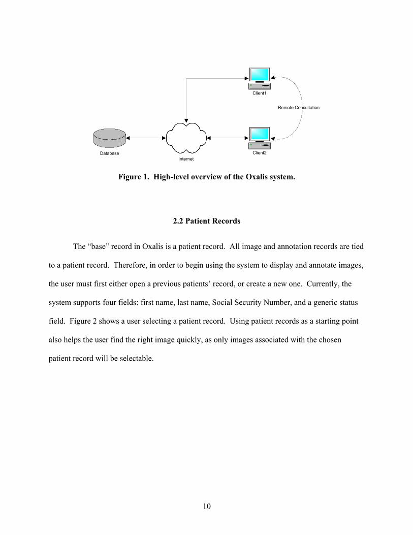
over an intra- or intranet, as shown in Figure 1. The database is used as a repository for all data,
including binary image data, for a group of users. The client software is a Java program,
installed on the user’s machine, which acts as the user’s interface to the database. Using a
Virtual Private Network (VPN) connection or dedicated dial-up, users in entirely different
physical locations can share the same set of patient, image, and annotation data. This enables
clinicians to have remote consultations with colleagues, regardless of their physical location.
9
InternetDatabase
Client1
Client2
Remote Consultation
Figure 1. High-level overview of the Oxalis system.
2.2 Patient Records
The “base” record in Oxalis is a patient record. All image and annotation records are tied
to a patient record. Therefore, in order to begin using the system to display and annotate images,
the user must first either open a previous patients’ record, or create a new one. Currently, the
system supports four fields: first name, last name, Social Security Number, and a generic status
field. Figure 2 shows a user selecting a patient record. Using patient records as a starting point
also helps the user find the right image quickly, as only images associated with the chosen
patient record will be selectable.
10

Figure 2. Open Patient Screen. The user is selecting to open John Smith’s record.
In order to make the system as flexible and easily maintainable as possible, each record
type (such as patient records) used by the system has a dedicated database wrapper class, which
handles the vast majority of the queries pertaining to that record type. This makes it much easier
to change the layout or fields of a database table, as the developer need only change the
dedicated wrapper class (and any user interface components that directly display the table’s
fields). The only exception to this is when a foreign key field is affected by the change, in which
case the table that is referencing the foreign key (and its associated wrapper) will also need to be
changed.
2.3 Image Upload and Display
Once the user has selected or created a patient record, s/he can begin uploading images
into the system. This must be done because of the “distributed” nature of Oxalis – if all images
were stored on the user’s local computers, it would be difficult (if not impossible) to effectively
share patient and image information with fellow clinicians. Therefore, Oxalis stores all image
data centrally, in a database, where it can be accessed by multiple users simultaneously with
ease. This also helps system administrators perform backups of the image data, as they need
only backup the main Oxalis computer’s drive.
11
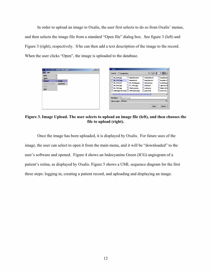
In order to upload an image to Oxalis, the user first selects to do so from Oxalis’ menus,
and then selects the image file from a standard “Open file” dialog box. See figure 3 (left) and
Figure 3 (right), respectively. S/he can then add a text description of the image to the record.
When the user clicks “Open”, the image is uploaded to the database.
Figure 3. Image Upload. The user selects to upload an image file (left), and then chooses the file to upload (right).
Once the image has been uploaded, it is displayed by Oxalis. For future uses of the
image, the user can select to open it from the main menu, and it will be “downloaded” to the
user’s software and opened. Figure 4 shows an Indocyanine Green (ICG) angiogram of a
patient’s retina, as displayed by Oxalis. Figure 5 shows a UML sequence diagram for the first
three steps: logging in, creating a patient record, and uploading and displaying an image.
12
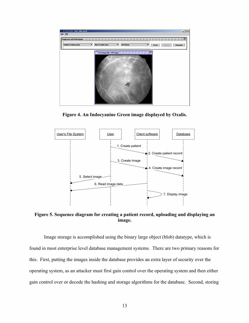
Figure 4. An Indocyanine Green image displayed by Oxalis.
Client softwareUserUser's File System Database
1. Create patient
5. Select image
2. Create patient record
4. Create image record
6. Read image data
3. Create image
7. Display image
Figure 5. Sequence diagram for creating a patient record, uploading and displaying an image.
Image storage is accomplished using the binary large object (blob) datatype, which is
found in most enterprise level database management systems. There are two primary reasons for
this. First, putting the images inside the database provides an extra layer of security over the
operating system, as an attacker must first gain control over the operating system and then either
gain control over or decode the hashing and storage algorithms for the database. Second, storing
13

the images directly on the server’s file system would both needlessly increase the time to
download an image (as it would require an extra connection to the server), and require
administrators to maintain a separate set of login credentials (for the server’s file system) for
each user to determine whether or not they were permitted to upload images.
The classes that interpret image data have been designed to be easily interchangeable or
expandable. This is accomplished using Java’s reflective libraries, which allow an executing
class to load other classes and libraries as needed at runtime. Currently, the system supports the
Joint Photographic Experts Group (JPEG) [13], Tagged Image File Format (TIFF) [14], Graphics
Interchange Format (GIF) [15], and Bitmap (BMP) [16] file formats, as these are the ones most
commonly used in the digital devices used by ophthalmic photographers. However, due to the
flexibility of the architecture, the Portable Network Graphics (PNG) [17], raw, or Digital
Imaging and Communications in Medicine (DICOM) [18] file formats could be added to the list
of displayable formats without changing or recompiling any of the core classes.
2.4 Diagnoses List
In order to annotate an image in Oxalis, the user must first select a diagnosis and
pathology from the diagnoses list, visible at the top of Figure 4, and enlarged below as Figure 6.
This leftmost dropdown box contains diagnoses, such as Diabetic Retinopathy, Age-related
Macular Degeneration, etc. Making a selection from this box causes the next one to update: if
the user selects “Diabetic Retinopathy” from the first box, the second one will contain
“Proliferative” and “Non-Proliferative”. Making a selection in the second box changes the third,
and so on. The user can also select “Unknown”, which will display a list of all available
pathologies (for the case where the diagnosis is not known ahead of time). The use of the
14

diagnoses list prevents users from accidentally corrupting patient records with typographical
errors, and provides a common nomenclature for an entire installation.
Figure 6. Diagnoses List. This figure shows the diagnoses list in its default configuration (top), and after the user has made a selection (bottom).
The diagnoses list is not “hard-coded” into the system. Instead, it is stored in the
database, and can be changed or added to by any user. The list is presented to the user in “tree”
form (like files in Windows Explorer) for editing, where “folders” contains all of the pathologies
for the diagnosis. Users can copy, paste, remove, or add to the list, as well as editing individual
entries. In order to ensure the integrity of an image review, if a user changes a list item (for
spelling, to change from an acronym to the full name, etc.) that has been used on an image, the
annotation on the image will remain as originally specified. However, the changed list item will
no longer be available for selection for future uses. Changes to the tree by a user are reflected
immediately in the list for all users. See Figure 7 for an example of editing a diagnoses list. For
these examples, we have used a set of common, informal ophthalmic diagnoses and pathologies;
however, the flexibility of the lists allows for a much more formal and specific classification to
be accomplished. One such possibility is using the International Classification of Disease (ICD)
[19] codes.
15

Figure 7. Diagnoses Tree. A user elects to edit the diagnoses list (left) and is presented with
the list in tree form (right). The table structure for the diagnoses list/tree is shown in Figure 8. Of special interest is
the “parentnum” field, which recursively references the “identifier” field. This sets up the
parent-child relationship in the list, and enables the hierarchy of the data to be only limited by the
length of the “identifier” and “parentnum” fields. Currently, the fields are each specified as ten
numeric digits long, for a total of ten billion entries.
The transformation has been optimized to only retrieve the list from the database when
the system initializes or a change is made to the list on a different computer. On all other
occasions, the “tree view” is directly transformed (by “walking the tree” in bottom-up order) into
the list in memory. For large lists/trees and slow network links, this optimization results in a
phenomenal improvement in performance. However, even over a 100 Megabit per second link,
the time to rebuild and display a forty-item list in memory was measured to be roughly half of
the time to requery the database (four seconds versus 8.5 seconds).
16

DiagnosesList
PK identifier
parentnumdescriptionlinecolorfillcolorchangeddeleted
1-N
Figure 8. Entity-Relationship model of the diagnoses list.
2.5 Annotations
Once the user has selected the appropriate annotation from the list, s/he clicks the “Draw”
button. The user then presses her primary mouse button over the image, and “drags” to create a
freeform polygon. See Figure 9 (top left). When the user releases the mouse button, the
annotation is automatically sent to Oxalis’ database for storage.
Once an annotation has been created, the user can click on it to select it (if it isn’t already
selected) and move it around the image (if necessary). The user can also select to hide an
individual annotation or all annotations on an image temporarily, and later restore them to view.
Additionally, the user can resize or reshape an annotation by selecting one of the “clip points”
(black rectangles over the vertices of the polygon) and “dragging” it. As the speed of the drag
increases, clip points neighboring the dragged point move with it (to a lesser extend), in order to
save time when making major corrections to a region. Finally, the user can elect to “delete” an
annotation. In order to preserve the integrity of diagnostic records, “deleted” annotations are
never permanently removed from the database, rather, they are marked as “undisplayable” and,
as such, will not be downloaded or displayed for a user unless he or she specifically select to
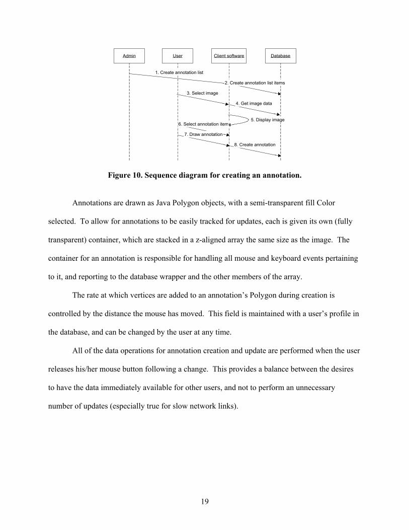
view deleted annotations. See Figure 9. Figure 10 shows a sequence diagram for creating the
diagnoses list, selecting a pathology, and annotating an image.
17

Figure 9. Image Annotation. The user has created an annotation on the image (top left). Note that the annotation color is semi-transparent. Colors are based on the selection in the diagnoses list. The user then moves the annotation into position on the image (top right). Next, the user reshapes the annotation slightly to refine the annotated region (bottom left). Finally, the user activates a context-sensitive menu for the annotation (bottom right).
18
Client softwareUser Database
8. Create annotation
Admin
1. Create annotation list
2. Create annotation list items
3. Select image
4. Get image data
5. Display image6. Select annotation item
7. Draw annotation
Figure 10. Sequence diagram for creating an annotation.
Annotations are drawn as Java Polygon objects, with a semi-transparent fill Color
selected. To allow for annotations to be easily tracked for updates, each is given its own (fully
transparent) container, which are stacked in a z-aligned array the same size as the image. The
container for an annotation is responsible for handling all mouse and keyboard events pertaining
to it, and reporting to the database wrapper and the other members of the array.
The rate at which vertices are added to an annotation’s Polygon during creation is
controlled by the distance the mouse has moved. This field is maintained with a user’s profile in
the database, and can be changed by the user at any time.
All of the data operations for annotation creation and update are performed when the user
releases his/her mouse button following a change. This provides a balance between the desires
to have the data immediately available for other users, and not to perform an unnecessary
number of updates (especially true for slow network links).
19

2.6 Image Groups
Generally, Florescein and Indocyanine Green angiography is not accomplished with a
single image. Instead, multiple images are taken at a fixed time interval as the dye takes effect.
To best display these images, Oxalis enables the user to create an image group, or sequence of
images, which can be displayed as one entity and “scrolled” through by the user.
In order to create an image group, all of the images in the group must first be uploaded to
the database. The user then selects the images in the image group creation screen, and “sends”
them to the group by clicking the right arrow icon. The user can then change the order of the
images within the group by clicking the up/down arrow icons, and remove an image from the
group by clicking the left arrow icon. Finally, the user can assign the group a name, and click
“OK” to create the group. See Figure 11.
Figure 11. The user has selected to create a group (left). The user then selects and orders the images, and gives the group a name (right).
Once the user has created the group, it is automatically displayed by Oxalis. See Figure
12. When the user clicks the scrollbar at the bottom of the image, Oxalis advances or rewinds
the “frame” of the sequence, displaying images in the order specified during group creation.
This enabled clinicians to clearly and easily see the changes as the dye takes effect. Any
annotation performed on an image within a group will always be displayed either with the group
20

or when the image is opened individually. Additionally, any annotations already present on a
grouped image will be displayed in the group. Figure 13 shows a sequence diagram for creating
an image group.
21

Figure 12. Three images within an image group. Note the position of the scrollbar, indicated by arrows. This group was created as an example, and may or may not represent
three images from the same patient.
Client softwareUserUser's File System DatabaseWeb Server
2. Select image
4. Create image record
3. Read image data
1. Create image
5. Display image
6. Create image record
7. Display image8. Create image group
9. Display screen10. Select images
11. Select order
12. Create group
13. Create image group record
14. Display group
Create additional images
Figure 13. Sequence diagram for creating an image group.
22

2.7 Templates
There are situations in ophthalmic photography where it may be unclear which section of
the eye was being studied for a given photograph. In these cases, it would be much more clear if
the photographs could be “hyperlinked” to a schematic or line drawing of either the retina or the
entire eye.
Oxalis enables the user to do this using “templates”, or pre-uploaded schematics. These
images are stored and displayed exactly as any other (so a template could be a photograph
instead of a drawing), but, instead of being annotated with pathologies and diagnoses, are
annotated with hyperlinks to images or image groups. Figure 14 shows a template image of the
retina.
Figure 14. A fundus (retina) template image. The upper images depict the retina in relation to the eye. The lower images detail the retina itself.
In order to distinguish between hyperlinks and regular annotations (which cannot be
created on a template), hyperlinks are drawn as rectangles instead of freehand polygons. The
position where the user initially presses the mouse button becomes one corner of the rectangle,
and the other three vertices “drag” with the user’s mouse movement. Once the user releases the
mouse, a dialog is presenting, asking the user to assign an image to this hyperlink. If the user
does so, a thumbnail of the image is displayed in the fields to the right or left of the template
23

image. Clicking on the thumbnail, or double-clicking on the rectangle on the template image,
will cause the system to open the linked image. Figure 15 shows a completed template image.
Figure 16 shows the sequence diagram for creating and annotating a template.
Figure 15. Completed template image.
24

Client softwareUserUser's File System Database
10. Select image
12. Create image record
11. Read image data
9. Create image
14. Display image
2. Select template file
4. Create template record
3. Read template data
1. Create template
5. Display template6. Prompt user for patient template creation
7. Create patient template record
8. Create patient template record
13. Annotate template
15. Assign image
16. Create template image record
Figure 16. Sequence diagram for creating a template image.
Both the image group and template functions use the predefined image display
architecture to display their images. They are extensions to the architecture, and required very
minimal changes to the other classes to implement. Due to the fact that an Oracle database is
used as the primary development environment for the project, and that Oracle is not in
compliance with the JDBC driver for binary large objects, changes to the primary database
wrapper were required to implement the storage and retrieval of template images, but otherwise
the addition of these features consisted of the addition of a few new tables to the database, a
small amount of new code to handle the features themselves, and a number of calls to other
portions of the architecture to perform the actual “work” of the features.
25

3.0 TECHNICAL DETAILS OF ANNOTATION
In order to enable users to efficiently display, annotate and share images, a number of
different features needed to be designed and implemented. First, an initialization system needed
to be designed. The main requirements for this system were that it allow users to easily change
their “home” database, and enhance, update and control the image display capabilities of Oxalis.
Second, the system needed a way for components to be notified of the creation or
modification of data records. The most important data records for the system the ones
concerning patients, images, and annotations. Many system components need to be notified
whenever a change occurs in any of these, a many-to-many relationship. It was therefore
imperative for the notification method to be efficient, both in implementation and in execution.
Third, the image data interpretation and display panels needed to be designed to enable
developers to efficiently modify or implement new image formats and specifications. Image file
formats are constantly being developed and modified, and it is important for the system to be
able to keep abreast of these changes. If a new format could not be added to the system in a
well-defined manner, it would greatly reduce the useable life cycle of Oxalis.
Fourth, annotation panels, which perform the drawing and display operations for
annotations, needed to be designed perform as quickly and effectively as possible. This included
designing an efficient annotation painting algorithm, so that the system would not be excessively
burdened redrawing annotations as the user performed a manipulation. It also required that a
balance be achieved between the user’s desire to have data available immediately, and the desire
to perform as few updates to the database as possible, so as not to waste processor time and
network bandwidth on unnecessary updates.
26

Fifth, it was decided that the standard approach taken by many of the currently available
systems, of allowing the user to enter plain text for annotations, was inefficient for users, who
have to enter similar information each time, and for database storage, as the same description
must be archived repeatedly. As a solution to this problem, the concept of a selectable list of
available annotations was developed. In order to complete the design of this component, it was
necessary to provide users with a graphical editing tool for the selectable list.
Finally, in order to allow annotated images to be as portable as possible, it was necessary
to provide users with a method to export their images and annotations from Oxalis to a
commonly available file format. The formats decided on for this were JPEG images, and
HTML/JavaScript files, which enables images annotated in Oxalis to be publishable to the World
Wide Web. Additionally, in order to allow developers to extend the capabilities of Oxalis, it was
necessary to provide a central data aggregation component, which is guaranteed to contain the
most current data being used by the system. During design, these two goals were tied together,
with the data manager being designed first, and the component that performs the export to
HTML serving as an example of how a component can interact with the data manager.
Each of these components will now be described in detail.
3.1 Initialization
One of the goals in the design of Oxalis was to make it a distributed system, giving users
the ability to easily share information regardless of physical locality. To accomplish this, we use
a database to store all file, image, and annotation data centrally. However, in certain situations,
it is necessary for a user to connect to more than one Oxalis database. One such situation would
be a remote consultation, when a clinician from a different hospital or health system would be
27

called on to diagnose a patient. In this case, it would be much more efficient for the patient’s
data to be entered in the database closest to him/her, as opposed to the one nearest the consulting
clinician. However, it would be both inefficient and burdensome for a user to have to edit and
recompile Java source code in order to switch databases.
A related design goal was to have the image interpretation performed by Oxalis be easily
configurable by the user without having to edit and recompile the source code. Image formats
and specifications are constantly being updated, and new formats are continuously being
developed. The past seven years have seen the advent of PNG (1995), several updates to the
Digital Imaging and Communications in Medicine (DICOM) standard (2003), and the advent of
JPEG2000 (2000), among other changes. In order for Oxalis to change with image
specifications, there must be a method for a single developer or group of developers to
implement the changes to the image processors, and then deliver these changes to users. Most
importantly, it must be relatively simple for a user to add, change, or update an image interpreter
on his or her own Oxalis installation.
In order to solve both of these problems, Oxalis uses an initialization file. This file
contains all of the information needed to connect to a local or remote database, as well as all of
the information necessary to install and initialize the image processors used by Oxalis. An
eXtensible Markup Language (XML) file is used for initialization because it can be specified and
checked using a Data Type Declaration (DTD) [20] to prevent typographical errors from halting
initialization, and parsed using the Java API for XML Processing (JAXP) [21]. A sample XML
initialization file for Oxalis is shown in Figure 17. The rest of this document describes the
elements of this file in detail, and describe the steps necessary to either change the user’s
database, or install or remove an image processor.
28

<?xml version="1.0" encoding="ISO-8859-1"?> <!DOCTYPE root-element SYSTEM "OxalisINI.dtd"> <Oxalis> <database> <driverClass>database.MySQLImagingDatabase</driverClass> <host>localhost</host> <db>someDB</db> <username>sample-user</username> <password>sample-pass</password> </database> <imageInterpreters> <class>imagedisplay.JPGGIFImageDisplayPanel</class> <class>imagedisplay.TIFImageDisplayPanel</class> <class>imagedisplay.BMPImageDisplayPanel</class> </imageInterpreters> <userPrefs> <listLength>50</listLength> <pointSpacing>15</pointSpacing> </userPrefs> </Oxalis>
Figure 17. Sample XML initialization file for Oxalis.
The first two lines of the file contain the XML version and encoding scheme, and the
metadata used by JAXP to validate and parse the file. After this comes “<Oxalis>”, the root
element for this file. All of the initialization parameters are child elements of Oxalis, as required
by the XML specification.
The first child element specifies the source database. It contains all of the information
Oxalis will use to initialize, connect to, and interact with the database. The first subelement in
this group is the database “driverClass,” which is the fully qualified name of a Java class that
implements the database.ImagingDatabase interface. The remaining parameters are the host
(Domain Name System [DNS] name or Internet Protocol [IP] address), database identifier (as
required by the Database Management System), username, and password. These four parameters
will be passed as Strings to the driver during construction. Actual initialization of the database
driver is accomplished reflectively using Java’s Constructor class [22].
29
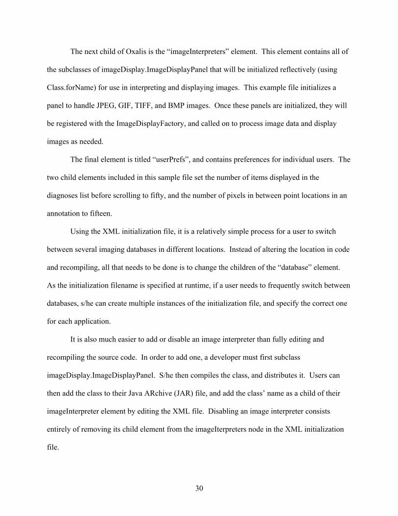
The next child of Oxalis is the “imageInterpreters” element. This element contains all of
the subclasses of imageDisplay.ImageDisplayPanel that will be initialized reflectively (using
Class.forName) for use in interpreting and displaying images. This example file initializes a
panel to handle JPEG, GIF, TIFF, and BMP images. Once these panels are initialized, they will
be registered with the ImageDisplayFactory, and called on to process image data and display
images as needed.
The final element is titled “userPrefs”, and contains preferences for individual users. The
two child elements included in this sample file set the number of items displayed in the
diagnoses list before scrolling to fifty, and the number of pixels in between point locations in an
annotation to fifteen.
Using the XML initialization file, it is a relatively simple process for a user to switch
between several imaging databases in different locations. Instead of altering the location in code
and recompiling, all that needs to be done is to change the children of the “database” element.
As the initialization filename is specified at runtime, if a user needs to frequently switch between
databases, s/he can create multiple instances of the initialization file, and specify the correct one
for each application.
It is also much easier to add or disable an image interpreter than fully editing and
recompiling the source code. In order to add one, a developer must first subclass
imageDisplay.ImageDisplayPanel. S/he then compiles the class, and distributes it. Users can
then add the class to their Java ARchive (JAR) file, and add the class’ name as a child of their
imageInterpreter element by editing the XML file. Disabling an image interpreter consists
entirely of removing its child element from the imageIterpreters node in the XML initialization
file.
30

3.2 Event Model
Oxalis enables the user to have multiple images, image groups, and image templates open
at any given time, and each of these images can have multiple annotations. However, there are
many system components that must be notified whenever any of the images or annotation
records change, or when new records are created. One possible solution to this would be to have
each component that can change or create a data record directly call a method on each
component that must be notified of these changes. However, the implementation of this solution
would be inefficient, as each new system component that requires notification would need to
have its methods added. Both the component performing the modification or creation and the
new component would then need to be rebuilt.
Instead of a strictly hard-coded approach, Oxalis uses a series of data events and data
event handlers to pass information and notifications around the system. Data events are events
that are fired whenever the user creates, modifies, or removes a data record. Data event handlers
are system components that are capable of receiving and processing data events. An example of
a data event is when a user deletes an image, the corresponding handler for this event could
provide a confirmation window and/or place a copy of the image in a “recycle bin”.
The three main record types which require this event model to be in place are 1) patient
records, which contain all of a patient’s data as well as serving as the parent data for the other
records; 2) image records, which contain the image’s description, file name, and binary raster
data; and 3) annotations, which contain the series of points outlining the shape, as well as the text
and color of the annotation.
The realization of this design in Oxalis uses an event model similar to the one used by the
standard Java Abstract Windowing Toolkit (AWT). Components that wish to be notified of a
31

data event implement a “listener” (handler) interface for that event. Components that will
dispatch notifications of these events have an “addListener” method, which adds a handler to the
list of components that will be notified when the event is triggered. An example from the AWT
would be a component that wishes to be notified when a button is pressed. The component, the
handler in this example, implements the ActionListener interface, and its single method,
actionPerformed. The button, the firing component in this example, has an addActionListener
method, which adds the component to the list that will be notified when the button is pressed.
In Oxalis, the three main events are succinctly named PatientEvent, ImageEvent, and
ShapeEvent, respectively, and the handlers for each of the events are named PatientListener,
ImageListener, and ShapeListener. System components that generate these events have an
“addListener” method which allows a handler to be added to the list that will be notified when
the even is thrown. Each of these events, together with their trigger conditions, data, and
requirements to be notified of them, will now be described in detail.
A PatientEvent is fired whenever a patient’s record is opened, closed, deleted, modified,
or created. These events are fired by the NewPatientPanel and the OpenPatientPanel, and are
dispatched to any object that has implemented the PatientListener interface and registered with
the panels through the addPatientListener method. The addPatientListener method is static in
each class, allowing an object that wishes to receive patient events to register to do so regardless
of the order objects are initialized, and without having either of the panels passed via the
constructor or by searching the ClassRegistry. A large number of objects in the default Oxalis
distribution register to receive PatientEvents, as all images (and image lists) are tied to patient
records.
32
An ImageEvent is the image counterpart to the PatientEvent. They are fired by the
ImageOpenPanel and ImageUploadPanel, and dispatched to all objects that have implemented
the ImageListener interface and registered to receive events via the addImageListener method.
Like their counterpart patient panels, these methods have also been declared static to allow for
the easiest access by other objects. Currently, the ImageListener interface is used mainly by the
main Oxalis object (to display images once they have been created or opened) and the
DataManager interface (to maintain a reference to the currently-opened image for export and
other purposes).
ShapeEvents are a slightly different type of event. They are fired by individual
PolygonPanels (for images) and RectanglePanels (for templates) when the user begins or finishes
drawing a new annotation, or modifies, selects, deselects, or double-clicks on an old annotation.
In order to receive these events, an object must first implement the ShapeListener method, and
second register with the appropriate BasePanel that contains the annotation panel firing the
event. As there can be multiple BasePanels in existence at a given time, and not all objects wish
to receive all shape events, it was not possible to declare the addShapeListener method static.
However, for objects that do wish to receive all ShapeEvents from the system, the
BasePanelFactory and TemplateDisplayFactory contain static versions of these methods which
will cause the object to be registered with every BasePanel or TemplateBasePanel that is created.
Each of the three events contains three methods in addition to the constructor: getSource,
which returns the component panel that originated the event; getData, which returns an event-
specific record that pertains to the event (e.g. an ImageRecord for an ImageEvent) and getType,
which returns an integer code identifying the type of event. These codes can be matched with
33
statically declared variables in each event to provide further information to objects receiving the
event.
In addition to the benefits from enabling system components to be efficiently notified
when data records are created or modified, the event model also enhances the extensibility of the
system. A developer designing a component that needs to be notified of changes to patient,
image, or annotation records can implement the appropriate listener methods, and add his or her
component to the list that will be notified when the even occurs. This enables developers to
receive and handle the data event without first needing to edit the core component responsible
for generating the event. A future direction for the event model would be to design an
intermediary component which performs all registration of both handlers and event generators.
This component would index the methods required for handler implementation reflectively at
run-time, and map capable handlers to the appropriate event generators. This would provide a
central point for both handlers and generators, without needing any knowledge of the component
generating or the components receiving the event. It would also enable developers to extend the
event model itself by registering a generator for a new event type.
3.3 Image Panels
As previous stated, one of the design goals for the Oxalis system was to allow developers
to quickly extend or modify the image handling capabilities of the system, and to allow users to
easily control the image handlers that are installed. The creation of the XML initialization file
offers a solution to the second half of this problem, but does very little to alleviate the first part.
In order for developers to be able to quickly design and implement a processor for a new or
updated image specification, it was necessary to design Oxalis such that a clear and well-
34
structured specification for how the system chooses an image reader and displays an image could
be given to developers.
The specification for an image interpretation and display component in Oxalis uses an
abstract parent base class called ImageDisplayPanel. Any panel that wishes to display images
for Oxalis must subclass this panel. In return, developers can be guaranteed that only the
methods present in ImageDisplayPanel will be called by Oxalis, and can be made aware of
exactly what the system expects when each of these methods is invoked. The three methods
present and declared abstract in ImageDisplayPanel are getDisplayableTypes, setImageRecord,
and getImage. Each of these methods will now be described in detail, followed by an example
sequence of the system loading an image handler and displaying an image.
The first ImageDisplayPanel method, getDisplayableTypes, returns an array of type
String. Each element of this array is expected to be a file extension (such as JPG, GIF, or TIF)
that this ImageDisplayPanel wishes to provide display capabilities for. If two panels register to
handle the same type of image, the one which is processed last during initialization will be the
one that is used.
The second ImageDisplayPanel method, setImageRecord, sets the panel’s sets the panel’s
image data for display. Once this method has been invoked, the panel should immediately
process the image data and display the image. It should also set the preferred size, minimum
size, and maximum size to be the size of the image, so that layout managers will be able to
correctly lay out the component. When this method returns, the ImageDisplayPanel is expected
to be fully rendered (or pre-rendered) and ready for display.
35
The final ImageDisplayPanel method, getImage, returns the image this panel is
displaying. This can then be processed directly by export or rendering methods more advanced
than simply displaying the image.
Once a new ImageDisplayPanel has been created and compiled, only two steps need to be
accomplished by a user or administrator for it to be installed. First, the class file must be copied
into the user’s Java ARchive (JAR) file with the other components of the system. Second, an
entry needs to be added to the user’s XML initialization file under the imageInterpreters element,
which gives the fully qualified class name of the ImageDisplayPanel.
As shown in Figure 18, the main Oxalis object does not directly instantiate
ImageDisplayPanels through a call to their contructor. Rather, it delegates this responsibility to
the ImageDisplayFactory object. This object is responsible for indexing the displayable types of
each of the ImageDisplayPanels, selecting the correct type of ImageDisplayPanel when Oxalis
requests that an image be displayed, instantiating the panel, and causing the panel to render the
image. The ImageDisplayFactory then returns the panel to Oxalis, ready to be displayed.
During initialization, each entry in the imageInterpreters section will be parsed by the
system, and the Class object for each will be passed to the registerImageDisplayPanelType
method of the ImageDisplayFactory. There, it will be checked to ensure that it is a subclass of
ImageDisplayPanel. If it is, it will be asked for the file types it wishes to display (via the
getDisplayableTypes method), and added to the ImageDisplayFactory’s cache of displayable
panels.
36

When the user opens an image, Oxalis calls the ImageDisplayFactory’s
createImageDisplayPanel method, which searches the cache for the appropriate panel, invokes
the panel’s setImageRecord method, and returns the panel to Oxalis for display.
Initialization File Intialization parser Oxalis Main Object ImageDisplayFactory User
1. Begin parsing
2. Parse file
3. Request image display classes
4. Return classes
5. Register image display class
6. Repeat for all classes
7. Select image
Request appropriate ImageDisplayPanel
ImageDisplayPanel
9. Select ImageDisplayPanel
10. Instantiate panel
11. Deliver image data
12. Render image offscreen
13. Return ImageDisplayPanel
Figure 18. Sequence diagram for initializing, selecting, and displaying images.
This system, involving reflective loading, caching, and implementation of an abstract
class, allows users and developers to easily extend the image display capabilities of Oxalis. For
the sake of comparison, the steps necessary for a strictly hard-coded implementation of image
display capabilities would require a developer to create and compile the image display class, and
then either obtain and compile the user’s current installation classes or give the user precise
37

instructions in the changes needing to be made to the registering classes. The user would then
need to make these changes, and rebuild the entire source code.
3.4 Annotation Panels
In order to make the process of annotating an image as easy and efficient as possible for
the user, three main issues needed to be resolved. First, due to the large number of shapes that
would likely be present, and the semi-transparent nature of the shapes, a highly efficient
algorithm for drawing and coloring (painting) the annotations needs to be developed. An
inefficient painting algorithm would result in several problems, such as a noticeable time in
between the background being painted and a shape being painted (flicker), a shape not painting
synchronously to the user’s mouse movements (lag), and increased processor and memory
utilization. Second, the user should have maximum freedom in deciding how their shapes are
drawn. This includes configuring the number of points per circumference, the total number of
points and the rate at which points are placed on a polygon. Third, a balance needs to be
achieved between user’s desire to have the annotation information instantly available in the
database (so that it can be accessed by other clinicians) and the user’s desire to not have to wait
for a database update to occur every time s/he moved the mouse during an annotation.
To maximize the efficiency of the painting algorithm, Oxalis places the annotations into a
“stack” of panels using Java’s JLayeredPane object. Each panel in the stack contains one
annotation, and performs all of the painting and movement for only that annotation. As the
background of each of the panels is transparent, only annotation shape needs to be repainted, and
the painting process can be “clipped” (narrowed in scope) as a result. Therefore, instead of
repainting the entire panel, only the bounding box around the shape is painted.
38

The user’s mouse events (such as clicking, movement, and drag) are intercepted by the
highest annotation panel in the stack. If a panel determines that the event does not apply to its
annotation, because the user has clicked outside the shape or the shape is unselected, for
example, the mouse event is forwarded to other annotation panels for processing.
For the sake of comparison, assume all of the shapes had been placed in the same panel.
Because shapes can overlap and intersect each other, it would be necessary to either repaint the
entire panel every time the user manipulated a shape, or calculate the area in which the user’s
current shape intersected other shapes and add that area to the section to be repainted. Either of
these methods would require a much larger amount of processing and/or painting time than the
method presented above. It would also be necessary to implement an algorithm to control the “z-
order”, the height of each shape relative to the user’s eye (which controls how shapes overlap
each other). Furthermore, it would be necessary for the containing panel to perform a search
through all of the shapes to determine which one to apply a mouse event to.
To solve the problem of enabling users to configure the rate at which points are placed,
and regulate the number of points placed per annotation, the first item that was required was an
algorithm for deciding exactly how and when to place points on an annotation. The standard
Java Runtime Environment (JRE) fires mouse events (most notably movement or drag events for
this application) on a fixed time interval, regardless of the speed with which the user moves the
mouse. This means that a slow steady mouse drag fires more mouse events than a quick one.
This has a decided impact on the algorithm chosen, as an algorithm that relied on the number of
mouse events that had occurred would multiply this effect, resulting in far fewer than the desired
number of points being created if the user moved the mouse hurriedly. Therefore, the point
placement algorithm used by Oxalis is based on the distance in between the location of the
39

current mouse event and the last point added to the annotation shape. This is still subject to the
JRE’s policy of firing mouse events, but is guaranteed to place a point at the location of the first
mouse event beyond the desired distance. Finally, the distance field is added to the initialization
file under the “userPrefs” element, as this is more efficient for users than editing and recompiling
source code.
The third problem, balancing the number of database updates with the desire for
immediate information availability, concerns both network bandwidth utilization and user
efficiency. There are two extreme cases. In the first case, the database is updated every time the
user performs an operation, from moving an annotation one position to beginning to draw a new
annotation. This results in both high network utilization, as an extreme number of database
updates would congest the route between the user’s computer and the database, and poor
performance, as the user’s machine must wait for each update to occur. In the second extreme
case, the database is only updated when the user logs off or closes the image. This results in
bandwidth utilization that is low on average, but contains sharp peaks whenever the user
performs one of the update operations. It also results in poor performance for other users, as
they must wait for the image to be closed on the user’s system before updates will be reflected on
their systems. To balance between these two extremes, Oxalis performs a database update on an
individual annotation when the user releases the mouse button after s/he has performed an
update to an annotation. This results in an average, but relatively constant network utilization, as
updates are only processed once per change (the user first presses the mouse on the annotation,
then drags it to perform an update, then releases it). It also results in better performance for both
the current user and other users, as the updating user only needs to wait for one database update
40

to be performed per change, and other users only need to wait for the updating user to release the
mouse button in order to obtain the most current data.
The achievement of these three objectives allows Oxalis to function in a efficient and
professional manner. This, in turn, enables users to efficiently annotate images, and have access
to annotation information provided by others, which is the over-arching goal of the Oxalis
project.
3.5 Diagnoses List and Diagnoses Tree
As previously noted, the vast majority of currently available image annotation systems
use plain text, entered by the user, to annotate the image. However, using this method could
result in uncertainty of diagnosis, caused by either a typographical error or a difference in
notation (such as one clinician using an acronym to describe a pathology while another does not).
It is also inefficient, as diagnoses and pathologies must be typed by clinicians each time, and
stored as a unique string in the database. While an “intelligent agent” or natural language
processing system, such as Aria [23], the Remembrance Agent [24] or the Papillon
representation system [25], which fill in the remainder of a word or phrase once a user has typed
an identifiable portion of it, could assist users in making annotation more efficient, the redundant
occurrence of text descriptions in the database would still exist, as would the possibility of
uncertainty in diagnosis.
As an alternative to plain text annotation, Oxalis users select from a pre-defined set of
lists of annotations, and then draw the selected annotation on the image, instead of entering text-
based descriptions. This is similar to the “concept-based approach” described by Gertz et al.
[26] See Figure 19 for an example list of possible annotations. This method eliminates the
41

uncertainty of text-based annotations, as all users in a particular institution or clinical setting are
forced to use the same notation. It also eliminates the redundancy of information in the database,
as the description of the annotation is only stored with the list itself.
Figure 19. Annotation list. In the top figure, the list is shown in its default configuration. In the bottom figure, the user has selected “Diabetic Retinopathy”, “Non-proliferative”,
and “Blot heme.” In order to maximize user efficiency and enable users to develop their own format and
nomenclature (or implement a known standard such as the International Classification of Disease
codes), it is necessary to provide a graphical method for users to edit the contents of the list
within the Oxalis system (as opposed to editing the database directly) and allow the sequence of
be as long as the user desired. This posed several problems. First, a table structure needed to be
developed that could accommodate the diagnoses list. Second, methods needed to be developed
to allow the user to efficiently edit the contents of the table, and transform the table to the
sequence of lists used for annotation.
The Entity Relationship Diagram (ERD) of the database table for the diagnoses list is
shown in Figure 20. Each item in the diagnoses list has a unique integer primary key stored in
the field “identifier.” Additionally, each list record must contain an integer in the “parentnum”
field, which is tied by a foreign key constraint to the “identifier” field. The integer found in the
“parentnum” field uniquely identifies the record which will serve as the parent of this record in
42

the list and tree. This system enables the list or tree to be efficiently stored and practically
unlimited (currently 1010) in length or width. The next four elements, “description”, “linecolor”,
“fillcolor”, and “altText”, control the appearance and text of the diagnoses list item, indicating
(respectively) the full description, the color the outline of the shape will be rendered in, the color
the shape will be filled with, and the text that will be displayed with the annotation.
DiagnosesList
PK identifier
parentnumdescriptionlinecolorfillcoloraltTextchangeddeleted
1-N
Figure 20. ERD for the diagnoses list table.
Three example records for the table are shown in Table 1. Note that the “ParentNum” of
the “Blot heme” record matches the “Identifier” of the “Non-Proliferative” record, and the
“ParentNum” of that record matches the “Identifier” of the “Diabetic Retinopathy” record. This
structure dictates that “Non-Proliferative” will be a child of “Diabetic Retinopathy”, and “Blot
heme” will be a child of “Non-Proliferative.” When the diagnoses lists are built from the
database, they will have the multiple select box structure shown in Figure 19, and when the tree
is built (see below), it will have the structure shown in Figure 21.
Table 1. Example records from the DiagnosesList table.
Identifier ParentNum Description LineColor FillColor AltText Changed Deleted 2 0 Diabetic Retinopathy 0 0 NULL -1 -1
10 2 Non-Proliferative 0 0 NULL -1 -113 10 Blot heme -4670860 1689827956 NULL -1 -1
43

In order to allow the user to edit the list, Oxalis uses Java’s JTree [27] object, which
displays items in a manner similar to “Windows Explorer” or other file browsers. See Figure 21
for an example of the diagnoses table displayed in tree form. By defining a custom
implementation of Java’s TreeCellEditor [28] interface, we were able to use predefined methods
to allow the user to edit the tree directly. When the user “double clicks” an item in the tree, a
dialog is invoked which allows the user to edit any or all of the fields of the list item. See Figure
22 for an example dialog. The user may also click the “Add”, “Remove”, “Copy”, and “Paste”
buttons to the right of the tree to perform addition, deletion or duplication of a list element. The
copy and paste operations function recursively – that is, copying a parent element automatically
copies all of its children as well. The copy and paste operations are also bound to their standard
Windows keyboard shortcuts (Ctrl + c and Ctrl + v, respectively). In order to insert or delete
nodes from the tree, we used the predefined Java methods, found in TreeModel interface [29]
and, more directly, in the DefaultTreeModel object [30]. Changes to the tree are replicated to the
database table immediately (as soon as the user clicks the “OK” button on the dialog, or invokes
the paste command).
44

Figure 21. Diagnoses table in tree form.
Figure 22. Diagnoses tree dialog.
However, allowing users to edit the diagnoses tree could pose a serious risk to the
integrity of diagnoses. If changes to the diagnoses tree were reflected in annotations created
prior to the change, it would enable a user to change an incorrect diagnosis by altering the
annotation’s text or removing it altogether. For this reason, once an item in the list has been used
in an annotation, it will no longer be directly changed in the database (via an “update” or
“delete” command) by Oxalis. Instead, the “changed” or “deleted” flag will be set (see Figure
20), indicating that the list item can no longer be used, but still allows previous annotations to
45

refer to it. An entry will also be created indicating the date and time that the annotation was
changed or deleted, as well as the new text of the annotation (if it was changed).
To transform the tree into the sequence of lists used during the process of annotating
images, we first developed a custom subclass of Java’s AbstractListModel [31].
AbstractListModel is a default implementation of the ListModel [32] interface, which is
responsible for storing and providing all of the data used by a JComboBox [33].
When the JRE builds (or rebuilds) a JComboBox, it first invokes the getSize method of
the list model to determine the length of the list The JRE then repeatedly invokes the
getElementAt method to receive each element in the list, and passes them to the object
responsible for rendering list items.
Our subclass of AbstractListModel, called “DatasetComboBoxModel”, encapsulates a
hash table. The hash table has two elements, a "key" and a "value". For the
DatasetComboBoxModel, the key is a record from a preceding list, and the value is an array
containing all elements of the current list. For example, from the records in Table 1, "Diabetic
Retinopathy" would be a key in the hash table of the second DatasetComboBoxModel, and
"Non-Proliferative" (as well as all other elements in the "Diabetic Retinopathy" list) would be
the elements of the value array. Datasets are added to the model using the “addDataset” method,
which takes the parent record (“identifier”), and child dataset as its two arguments. To switch to
a different dataset, the “setDataset” method is invoked, with the parent key as its argument. This
automatically causes the combo box to reacquire and render the list elements. When the user
selects an item from the list, the list immediately to its right (the first child list) switches its
dataset to the selected list item. It then directs its child list to switch datasets, and the change is
46
replicated through all remaining lists in a similar fashion. See Figure 23 for the public methods
of the DatasetComboBoxModel, as well as a brief description of them.
To optimize the update speed for editing the diagnoses lists and tree, the lists are built by
retrieving the data from the tree and descending it in a breadth-first enumeration. This saves the
system from making the numerous round-trip transmissions required to build the lists from the
database. The database is only queried for the list during initialization. Thereafter, only update
and delete queries will be performed to synchronize the user’s changes.
This design, involving the diagnoses tree, lists, and editing and control components,
completely eliminates the uncertainty text-based annotations would have introduced to
diagnoses. It enables users to develop and deploy a single diagnosis structure across an entire
institution, presenting a uniform “look and feel” to diagnoses and annotation of images.
47

public void addDataset(Object identifier, Object[] dataset)
Adds “dataset” to the hashtable, using “identifier” as the key. public void setResetKey(Object identifier) Set the key value to use when resetDataset is called to “identifier”. public void resetDataset() Reset the model to the default dataset, which is set using setResetKey. public Object getResetKey() Returns the key which is currently used as the default reset value. public void setDataset(Object identifier) Sets the currently displayed dataset to the one that has “identifier” as its hash table key. public boolean hasDataset(Object identifier)
Tests whether this identifier references any dataset in this model. public Object [] getDatasetKeys() Returns all current identifiers from the hash table. public Object getElementAt(int index) Returns the object from array position “index” in the current dataset. public int getSize() Returns the number of elements in the current dataset.
public Object [] getDataset(Object identifier) Returns the dataset referenced by “identifier” in the hash table. public Object getSelectedItem() Returns the currently selected item. public void setSelectedItem(Object anItem) Sets the currently selected item.
Figure 23. Public methods and comments for the DatasetComboBoxModel.
48

3.6 Export and Data Managers
In order to allow for future expansion of Oxalis, it was necessary to design a central
object that could be queried to obtain all of the current “active” data, such as opened patient
records, downloaded images, and annotations. The enables a developer to quickly accumulate
the data his or her application will require, process it, and return it to Oxalis (if necessary)
through predefined methods. In the future, it will also provide a single “checkpoint” for ensuring
that an application has sufficient privileges to obtain the data it is requesting. Currently, the data
manager is used by one object, which enables the user to export the current patient record,
images, and annotations to HTML and JPEG images, for display outside of the system. See
Figure 24 for an example of an annotated image in Oxalis, and exported to HTML.
49

Figure 24. The top image shows an annotated image in Oxalis. The bottom image shows the same image after it has been exported to HTML.
50

Figure 25 shows the public methods of the DataManager class, the object designed for
this purpose. Many of the methods are implementations of interfaces, such as the PatientListener
interface (see section 3b) or Java’s InternalFrameListener [34] interface. Through these
interfaces, the DataManager is constantly updated with the most current data being used by the
system. Developers can then invoke the getCurrentPanel method to obtain the most current
image, including annotations, or the getCurrentPatient method to obtain the current patient
information.
When the user selects to export an image to HTML, the system first queries the
DataManager through the getCurrentType method to obtain the current image type (an image, an
image group, or an image template). It then obtains the image’s panel through the
getCurrentPanel method, and the current patient record through the getCurrentPatient method.
Using Java’s BufferedImage class [35] and Sun’s JPEG codec [36], the image and annotations
are transformed to JPEG images. The HTML files are then created using a PrintWriter [37].
51

public Object getCurrentPanel()
Obtain the most current image panel activated by the user. public int getCurrentType() Returns an integer specifying whether the current panel is an image, an image group, an image template, or no known type. public PatientRecord getCurrentPatient() Returns the current patient information used by the system. public void internalFrameActivated(InternalFrameEvent event) Called by the system when an image is activated. This method is required for implementation of the InternalFrameListener interface. For the sake of brevity, the other six methods required for the interface have been omitted. public void patientOpened(PatientEvent event) Called by the system when a patient record has been opened. This method, is required for implementation of the PatientListener interface. For the sake of brevity, the other four methods required for the interface have been omitted. public void drawStarted(ShapeEvent event) Called by the system when the user has begun drawing an annotation. This method, is required for implementation of the ShapeListener interface. For the sake of brevity, the other six methods required for the interface have been omitted.
Figure 25. Public methods of DataManager.
52
3.7 Conclusion
The design and implementation of Oxalis successfully realizes the goal of enabling users
to efficiently display, annotate, and share images. An XML initialization file to enable users to
quickly change their source database and control the image processing capabilities of the system.
To enable system components to be notified of changes to data records, and enabled developers
to receive these notifications as well, Oxalis implements an event model similar to the one used
by Java’s AWT. To increase the ease with which Oxalis’ image display capabilities can be
maintained or enhanced, the system uses a strictly-specified structure of image display panels
and a display panel factory. In order for the system to render annotations in a reliable,
professional, and efficient manner, Oxalis was designed with an efficient painting algorithm and
annotation display structure. By designing the annotation process to begin with a selection from
a series of lists, instead of plain text entry, Oxalis eliminates uncertainty in diagnosis and
redundancy in database storage. Finally, Oxalis aggregates the most current system data in a
central object to aid developers in creating entirely new applications for use with Oxalis, and
enable users to export their data to the World Wide Web.
However, there are still many improvements that could be achieved. This version of
Oxalis is useable in a “trusted” environment, where machine-level authentication can be used to
decide whether or not a user has access to the data, and extensions to the system are made freely
available by developers. Unfortunately, it is not useable in an “untrusted” environment, where
concerns as to the safety of data and/or program code exist. The modifications needed for Oxalis
to function in such an environment will be the subject of the next chapter.
53

4.0 UNTRUSTED ENVIRONMENTS
The design and implementation of Oxalis discussed in the previous chapters is acceptable
for “trusted” environments, where there are no concerns for the security of the users’ data (due to
the presence of firewalls, isolated subnets, Virtual Private Networking, etc.) or for the protection
from unauthorized distribution of developers’ code (due to a public licensing agreement, for
example). The focus of this chapter is to describe the modifications to the design that would be
required if Oxalis’ environment were “untrusted”, instead. In such an environment, Oxalis itself
must provide some guarantee to both users and developers that their data and intellectual
property cannot be modified or distributed without their permission.
We begin this discussion by examining the changes necessary to safeguard the users’
data. We detail the steps necessary to protect the data from unauthorized access directly in the
database, and those necessary to protect the data once it been downloaded by Oxalis. This
includes placing a security layer between Oxalis itself and the data, to prevent a malicious
developer from designing a component expressly to distribute users’ data.
We then examine the steps necessary to provide some measure of security for the
intellectual property of developers. This also involves protecting the executable code in the
database, and in Oxalis. A brokerage architecture for obtaining code from distributed sources in
a secure manner has previously been designed by researchers at the University of Pittsburgh, and
will be discussed. We will also discuss the security measures that can be taken to prevent
unauthorized users from executing code, or from obtaining and distributing it.
54

4.1 Protecting the Users’ Data
Protecting the users’ data in an untrusted environment is of the utmost concern. If the
records in Oxalis contain Protected Health Information, or data that would allow a patient to be
identified and which relates to the past, present, or future health of the individual, then, in order
to be in compliance with the Health Insurance Portability and Accountability Act of 1996, an
institution must be able to demonstrate that the data is safe from unauthorized access. If the
networking environment for Oxalis cannot provide the guarantees necessary to demonstrate this,
than Oxalis must do so itself. In order to accomplish this, the data must be protected at three
points: in the database, during transmission, and once it has arrived in Oxalis. The first and last
of these points will now be discussed in detail. It will be demonstrated that security during
transmission follows from securing the database.
4.1.1 Protecting the Database
In order to safeguard the data, the database itself must be strongly protected. In the
current system, users that can read the Oxalis initialization file can quickly determine all of the
parameters necessary to connect directly to the database, which would allow them to read or
modify any record contained therein. For an untrusted environment, this is unacceptable, as it
allows any user that either has been authorized to use Oxalis or has gained control of a machine
with Oxalis installed to compromise any record in the system. The solution to this problem
involves two main components. First, a modification to the Oxalis architecture must be made,
placing a server between users and the database, so that the database can be isolated from direct
traffic; second, the data must be encrypted for storage and transmission.
55

If users can directly access the database over the network, no other security measures can
fully safeguard the users’ data from each other. Therefore, we must modify the original
architecture of Oxalis to include a server, and become a client-server-database distributed
architecture, as opposed to the untrusted form, where the server is the database itself. The
revised architecture is shown in Figure 26. Under this architecture, clients log in and
authenticate with the server, instead of the database. They then submit queries as command
strings or messages to the server, which first checks whether or not the client is authorized to
obtain the data, and then performs the query, returning the result to the client. If the database is
placed in an isolated network (accessible only to the server), it can be shielded completely from
any attack that does not originate either at the server, or locally (by logging in to the machine the
database resides on). Additionally, only the person responsible for maintaining the server needs
to know the username and password required to connect to the database.
56
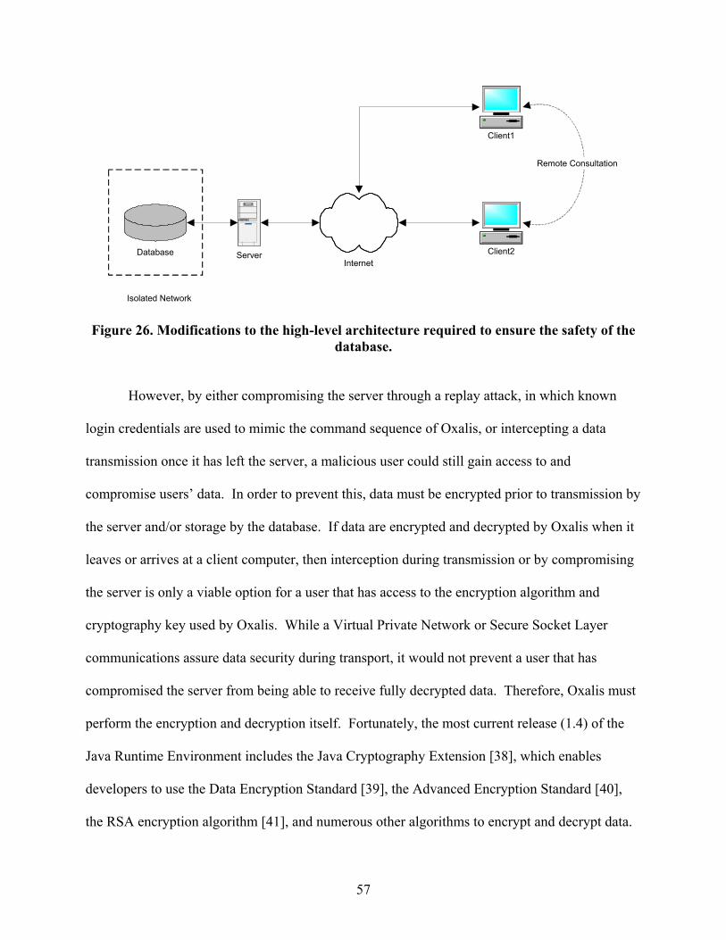
InternetDatabase
Client1
Client2
Remote Consultation
Server
Isolated Network
Figure 26. Modifications to the high-level architecture required to ensure the safety of the database.
However, by either compromising the server through a replay attack, in which known
login credentials are used to mimic the command sequence of Oxalis, or intercepting a data
transmission once it has left the server, a malicious user could still gain access to and
compromise users’ data. In order to prevent this, data must be encrypted prior to transmission by
the server and/or storage by the database. If data are encrypted and decrypted by Oxalis when it
leaves or arrives at a client computer, then interception during transmission or by compromising
the server is only a viable option for a user that has access to the encryption algorithm and
cryptography key used by Oxalis. While a Virtual Private Network or Secure Socket Layer
communications assure data security during transport, it would not prevent a user that has
compromised the server from being able to receive fully decrypted data. Therefore, Oxalis must
perform the encryption and decryption itself. Fortunately, the most current release (1.4) of the
Java Runtime Environment includes the Java Cryptography Extension [38], which enables
developers to use the Data Encryption Standard [39], the Advanced Encryption Standard [40],
the RSA encryption algorithm [41], and numerous other algorithms to encrypt and decrypt data.
57

However, the process of encrypting and decrypting the data will still result in decreased
performance of the system. To determine how detrimental the effects would be, we tested the
time required to open and read an image data file versus the time required to open, read, encrypt,
and decrypt the data file. Three file sizes were used, one each of 31 kilobytes (KB), 122 KB, and
1.38 MegaBytes. Each image file size was tested 1000 times. The parameters used for
encryption were: DES algorithm, Electronic Codebook mode, and PKCS #5-style padding. As
expected, the unencrypted form clearly outperformed the encrypted form. For the 31KB file, the
process of reading the file into memory took .762 milliseconds, on average, whereas the time to
read the file, encrypt it, and decrypt it took 32.944 milliseconds. For the 122KB file, reading the
file took 2.532 milliseconds, on average, and reading, encrypting, and decrypting took 171.966
milliseconds. For the 1.38 MB file, reading the file into memory took 81 milliseconds on
average, whereas reading, encrypting, and decrypting it required 1.891 seconds. A chart of these
results can be found at the end of this chapter, as Figure 34.
4.1.2 Protecting the Data Inside Oxalis
Securing the database and encrypting the data would both be nearly meaningless if a user
could access other users’ data directly in Oxalis, as they can in the version designed for trusted
environments. In that version, if a user has access to Oxalis, or to a computer that has Oxalis
installed, he or she can access any patient, image, or annotation record in the database.
In order to guard against this, Oxalis must include the capability to create user accounts
and roles. User accounts are unique identifying information for each authorized user of the
system, by which the system can authenticate them. The identifying information can be anything
from a username and password to a fingerprint or retinal scan. Roles are groups of user accounts
58
that have similar access privileges. Examples of roles would include “clinicians”, “residents”,
and “administrators”.
Users must then be allowed to specify permissions on records that they create, detailing
which users and roles have access (read, write, list) for them. These permissions must be
checked at the server, prior to transmitting data. If the data were transmitted and then filtered, a
malicious user could more easily disable the filtering algorithm, and gain access to the entire
record set.
The Java Authentication and Authorization Services (JAAS) extensions, which have been
included in version 1.4 of the Java Runtime Environment (JRE), could be used to implement
these changes [42]. JAAS enables developers to specify the method for obtaining a user’s
identifying information and authenticating that user in a “pluggable” fashion. The authenticating
agent is specified in a configuration file, and loaded at run time, which enables administrators to
switch authentication methods without recompiling the source code. The JAAS distributed with
Sun’s JRE implements username and password authentication, Windows New Technologies
authentication, public key authentication, and several other authentication methods. Developers
use a well-defined interface to obtain identifying information from users and validate that
information with a datastore. These methods would solve the first portion of the problem,
ensuring that only authorized users can access the system.
There are two possible architectures for specifying permissions on record sets. The first
architecture uses Java’s predefined security framework. In this framework, security restrictions
and permissions are defined by subclasses of the Permission [43] object. Subclasses of
Permissions would therefore need to be created, describing all of the critical operations that can
be performed on data records. The default extensions to the Permissions object enable users to
59
specify different file, socket, and service permissions, and it may be possible to modify one of
these to serve as the basic permission to control data access in Oxalis. Permissions are checked
by an object called the SecurityManager [44] when a critical system operation (reading a file,
opening a socket) is performed, or when an object explicitly asks that a permission be checked.
The data source for the SecurityManager in Java’s security framework is the Policy [45] object.
However, the Policy class is abstract, and the only default implementation provided by Sun uses
a file-based datastore to specify access. This would be unacceptable for the large number of
permissions required by the system, as individual annotations could have several different users,
roles, and access levels assigned to them. Therefore, a subclass of Policy would need to be
designed to query the database for its object permissions. Once a custom Policy and custom
subclasses of Permission were designed, checking object-level permissions would be a matter of
invoking the appropriate methods in the SecurityManager on the Permissions object at the server.
As the SecurityManager runs at a lower layer of the runtime environment than user code, this
would be the most secure method to safeguard users’ data. The Java Runtime Environment will
not allow code to alter or even access the installed SecurityManager unless 1) the code comes
from a trusted source, and 2) the code has a special system-level permission to do so.
The second possible architecture for specifying permissions on record sets uses stored
procedure calls in the database to control record access. The server checks with the database to
ascertain the access level a user has for a given dataset and filters the results accordingly,
returning the remainder to the client. However, this method would result in the security
mechanism running at the same layer as users’ code, making it much easier to defeat. A
malicious developer could much more easily create an object to disable this security architecture
than the previous one.
60
Once either of these architectures are fully designed, all that remains is the design of user
interface components to allow users and administrators to specify permissions. This would
require sending command strings to the server to obtain the list of accessible users and roles, and
the current security status of the object, and then to update those lists, encrypt them, and relay
them to the server for processing and storage.
Finally, socket, file, and service permissions would need to be developed to prevent the
server or client software from transmitting or storing users’ data in an unauthorized fashion.
This is especially important because the system is intended to be extensible, involving third-party
developers or other component sources. A malicious developer could design a component that
would appear to perform useful work, such as displaying the negative of a grayscale image, but
would also transmit the image data to a location outside of the institution’s network for further
dissemination. This could be prevented to some extent by fully testing new components before
deploying them on an institutional basis, but further preventative measures would be necessary to
completely guarantee the safety of users’ data. The latest revisions to Java’s SecurityManager
enable an administrator to control the socket and file permissions a component has on a
component-by-component, source-by-source, and/or user-by-user basis, and using these
permissions to effectively control the access system components have to the outside world would
also be required.
4.2 Protecting Developers’ Intellectual Property
In cases where the code and intellectual property of developers is not released to the
general public or is sold in source form to an institution, it becomes important to offer a means to
protect this property from unauthorized distribution. Failure to do so will result in decreased
61

income for third-party developers or loss of intellectual property entirely, which would
discourage others from developing extensions to Oxalis. However, in the course of securing the
code, the interoperability and extensibility of Oxalis must not be compromised – components
must be able to search for and obtain any data or processing function they require, provided they
have permission to do so.
If all system components and additions are installed on each client’s computer, the
potential for piracy becomes high. While various copy protection algorithms and methods, such
as Digital Rights Management [46] and executable encryption [47], have been developed, none
of these has proven to be one hundred percent reliable without disabling the user’s computer.
The backlash from users against these methods has also been strong, especially in cases where
the copy protection disabled devices it was never intended to influence [48].
The solution to this problem involves three main concepts. First, a brokerage architecture
must be designed so that either the user or a system component can search for and request a
remotely-stored object or method, regardless of the language the object is implemented in.
Second, there must be a method to download the remotely-stored object, or an interface to it, and
begin executing the desired methods. Third, there must be a method for a downloaded
component to request further processing from other remotely-stored components. At each stage,
the security of both remotely-stored objects and client data must be guaranteed.
4.2.1 Brokerage Architecture
Researchers at the University of Pittsburgh have developed a distributed, secure,
interoperable brokerage architecture known as Pegasus. This architecture enables a service or
application provider to register methods and processing capabilities they wish to make available
to clients with a central index. A client or object can then search the index for an object that
62

implements a set of desired methods or performs a desired operation. If an appropriate object is
found, the index server aids the provider in connecting to the client to deliver the object in
encrypted form. The client then petitions the index server for the appropriate decryption key and
decrypts the object. A diagram of this architecture is shown in Figure 27.
While this architecture does enable a client to securely search for and obtain an object
performing desired functionality, it does not specify how an remotely-stored object can be
instantiated on the local machine. This is the subject of the next section.
InternetCorporateNetwork
User A
User B
GatewayServer and
Internal ASP
Directoryand
VerificationServer
Services(Application
ServiceProvider)
IntellectualPropertyProvider
SoftwareProvider
Figure 27. Pegasus Architecture.
4.2.2 Object Instantiation
Once the code for an object has been downloaded by the system, the system must have a
way to instantiate, assign data to, and execute methods of the object, without first needing to
write the object to disk. For objects implemented in Java, an extension of Java’s
SecureClassLoader [49] and reflective library [50] can be used to accomplish these tasks. By
default, Java instantiates a ClassLoader as part of the virtual machine, to load objects into
memory as they are accessed. The main methods used by the ClassLoader to locate and load
63

objects are findClass, which converts a class name to an instance of the object’s class, and
defineClass, which transforms an array of bytes representing Java byte code into a Class [51]
object of the appropriate type. The SecureClassLoader is an extension to the ClassLoader
architecture, which enables the runtime environment to determine the access rights a code source
will have. Once an array of bytes has been resolved into a Class object by the ClassLoader, it is
possible to instantiate the object directly using the newInstance method, which returns a
reference to the newly-contructed object, or by using the Constructor [52] class. The Constructor
class is a member of Java’s reflective library. Its name refers to the method normally used to
directly instantiate an object, which in C++ and Java is called the “constructor method.” Java’s
Contructor class enables a developer to search for and access the constructor methods of an
object without knowing anything about the object at compile time, and use these methods to
instantiate the object. Note that the byte code is never written to disk; it can be loaded, resolved,
and instantiated entirely in memory, which makes it extremely difficult to obtain and/or
distribute the code via unauthorized means.
Using a subclass of SecureClassLoader, as well as the Java Cryptography Extensions, it
is possible to download, decrypt, instantiate, and execute a remotely-stored object, if the object
was written in Java. However, there are a large number of applications that could interoperate
with Oxalis, but have already been implemented in a different programming language, such as
C++ or Visual Basic. These objects pose a special challenge for code security, as they are
generally installed in binary executable code, which by itself would be sufficient to distribute
and run the application.
To solve this problem, the Common Object Request Broker Architecture (CORBA) could
be used. This architecture enables an application to execute methods on an object that resides on
64

a remote server. Under CORBA, objects publicize a “stub”, an interface containing all of the
public methods other objects should be allowed to access. When an object invokes one of the
methods in a stub, the arguments are seamlessly passed to the host machine over the network,
where they are processed, and the results are returned to the requestor. This means that the
binary code and data processing reside on the remote machine. Only the stub and result set from
the operation are passed to the client. This guarantees the safety of the binary code, since only
the byte code for the stub is transmitted. However, if too many clients attempt to access the
same object at the same time, the host computer may become overburdened. Currently, CORBA
libraries exist for C, C++, Visual Basic, and Java, making this an ideal architecture to use for
binary code blocks that are not written in Java.
In some cases, it is necessary to establish bidirectional communication with a remotely-
stored object. An example of bidirectional communication would be the client application
invoking a method on the remotely-stored object, which in turn causes the remotely-stored object
to invoke a method on the client application. Generally, it should be possible to eliminate the
need for bidirectional communication through interface and return type definition, but, in cases
where it cannot be avoided, it is important to deliver the relevant client data and methods as a
newly-created data interface instead of passing a reference to the entire client application. If the
client application is passed, a remotely-stored object provider with knowledge of the Application
Programming Interface of the client application could more easily obtain unauthorized data.
Using the data interface, on the other hand, the client application can specify exactly which data
elements the remote-stored object has access to (through the inclusion of “getDataElement”
methods), and what bidirectional methods are available (through the inclusion of
“setDataElement” methods).
65

It would be inefficient to download, decrypt and instantiate an object every time it was
required. For most applications, if the remotely-stored object could be downloaded into memory
and instantiated once, and then “looked up” locally each time it was required, it would greatly
increase efficiency. In order to accomplish this, an entirely new object (called the ClassRegistry)
will now be presented.
4.2.2.1 The ClassRegistry Object. The ClassRegistry exists to provide a reference to
previously-instantiated objects. This is important for two reasons: first, it enables objects to first
ascertain whether a remotely-stored object has previously been instantiated, and second, it
ensures that the remotely-stored object will not go out of execution scope and be garbage
collected by the runtime environment. The current “trusted environment” version of Oxalis uses
a ClassRegistry to maintain references to single-use objects. We will begin by discussing the
current form and the functionality it provides, and then move on to discuss enhancements to it
that would enable it to function effectively in an untrusted environment.
The public methods of the ClassRegistry object currently used by the system are shown
in Figure 28. If an object wishes to register itself with the ClassRegistry, it passes the class name
it wishes to register under as the “className” argument, and itself as the “classObject”
argument, to the registerClassObject method. The ClassRegistry will then check to make sure
that the object is in fact of the appropriate type (assignable from the “className” argument),
and, if the check passes, store a reference to the object in an index. If an object wishes to obtain
a previously-registered object, it invokes the “getClassObject” method with the appropriate class
name, and if the class name is found in the index, the object that last registered with that name
will be returned.
66
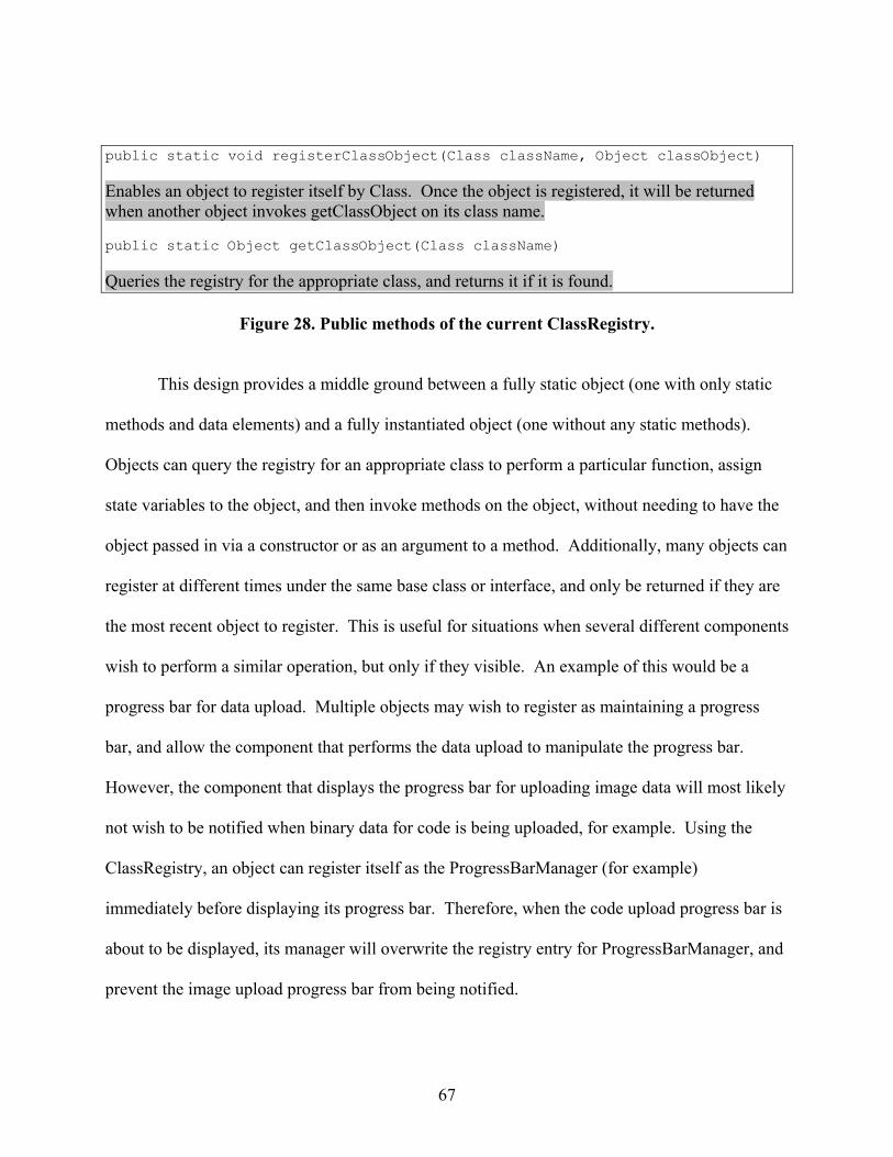
public static void registerClassObject(Class className, Object classObject) Enables an object to register itself by Class. Once the object is registered, it will be returned when another object invokes getClassObject on its class name. public static Object getClassObject(Class className) Queries the registry for the appropriate class, and returns it if it is found.
Figure 28. Public methods of the current ClassRegistry.
This design provides a middle ground between a fully static object (one with only static
methods and data elements) and a fully instantiated object (one without any static methods).
Objects can query the registry for an appropriate class to perform a particular function, assign
state variables to the object, and then invoke methods on the object, without needing to have the
object passed in via a constructor or as an argument to a method. Additionally, many objects can
register at different times under the same base class or interface, and only be returned if they are
the most recent object to register. This is useful for situations when several different components
wish to perform a similar operation, but only if they visible. An example of this would be a
progress bar for data upload. Multiple objects may wish to register as maintaining a progress
bar, and allow the component that performs the data upload to manipulate the progress bar.
However, the component that displays the progress bar for uploading image data will most likely
not wish to be notified when binary data for code is being uploaded, for example. Using the
ClassRegistry, an object can register itself as the ProgressBarManager (for example)
immediately before displaying its progress bar. Therefore, when the code upload progress bar is
about to be displayed, its manager will overwrite the registry entry for ProgressBarManager, and
prevent the image upload progress bar from being notified.
67

In order to provide support for the distributed, interoperable code sources in the untrusted
environment, several additional functions need to be added to the ClassRegistry. First of all, it
must implement the same query functionality as the index server in Pegasus. It would be
unrealistic to expect code to first query the index for desired functionality, and then become
aware of the class name of the objects. Second, the ClassRegistry must provide security
mechanisms to ensure that objects have permission to access each other in the desired manner.
Third, the ClassRegistry would need to be modified to support multiple objects of the same class
type, so that one remotely-stored object could not accidentally overwrite another.
Using Pegasus, Java’s SecureClassLoader, CORBA, and a modified ClassRegistry, the
system could now download and instantiate an object while guaranteeing the security of service
provider’s intellectual property. It could also access the object without downloading it, if it has
already been downloaded once in this execution instance. However, there are many cases where
one remotely-stored application may wish to obtain special processing from another. To fulfill
this goal, it is necessary to ensure that objects cannot gain access to data they were not intended
to have. For instance, if the first remotely-stored object is allowed to access all of the
annotations to an image, but a second is only supposed to access a single annotation, it would be
hazardous if the way the two objects interacted involved passing the entire list of annotations
back and forth. Therefore, a series of interfaces, describing exactly what data a remotely-stored
object will need in order to perform its functions, as well as what data it is capable of providing,
need to be designed.
68

4.2.3 Interoperability Interfaces
A balance must be achieved between the desire for components to be able to interoperate
with each other, and the need for security of the users’ data. If data is too freely disseminated,
the risk for alteration or corruption, whether through malicious or accidental means, becomes
high. On the other hand, if data is too tightly controlled, interoperability of components would
be impossible, as one component could not determine or provide the appropriate data to another.
To achieve this balance, each of the remotely-stored objects that wishes to interoperate
with others will be required to publicize an interface containing all of the critical operations, as
well as the data required to perform those operations. Interfaces may implement a security
mechanism that passes custom Permission objects to the SecurityManager, to ensure that data is
not being obtained in an unauthorized manner. These interfaces can then be checked by
administrators before agreeing to use the object, to ensure that each of the methods and data
elements are actually required for the object to function, and that it is not providing sensitive data
to other objects indiscreetly.
Once the interfaces have been declared and approved, they can register with the
ClassRegistry. Other service providers can be notified of the capabilities of the new interfaces,
and, when their components are loaded into the system, can use either the ClassRegistry or the
index server to locate the appropriate object.
4.2.4 Example
This section presents a sequence of block diagrams with descriptions that detail the
process of loading, instantiating, and establishing interconnectivity between remotely-stored
components. We begin with Figure 29, which shows a simplified view of the system at startup.
69

Note that for the purposes of this example, the server and image database, as well as the index
server for Pegasus, have been removed from the diagrams.
ClientApplication Database
SecurityManager Policy
ClassLoader
Figure 29. Simplified view of the system at startup
This figure shows the ClientApplication ready to begin loading plugins. The
SecurityManager will handle all security checks by passing them to the Policy, which will check
the permission in the Database. The ClassLoader will retrieve plugin byte code from the
Database, and instantiate it for the ClientApplication. At this point, the ClientApplication
contains all relevant data for the application.
70

ClientApplication Database
SecurityManager Policy
ClassLoader
PluginA DataInterfaceA
Figure 30. First remotely-stored component has been loaded.
Figure 30 shows the ClientApplication, having loaded its first remotely-stored object
(PluginA). To do this, it called the ClassLoader, which loaded PluginA’s byte code from the
Database (after finding it in the Pegasus index). Once PluginA is loaded, the ClientApplication
gives it a DataInterface (DataInterfaceA) which contains “getYyy” and “setYyy” methods to
access the data PluginA will require. DataInterfaceA will reference the SecurityManager any
time PluginA attempts to invoke a method, to check whether or not PluginA has permission to do
so.
71

ClientApplication Database
SecurityManager Policy
ClassLoader
PluginA
RemoteServerA
DataInterfaceA
Figure 31. A remote object loaded through CORBA
Figure 31 shows a remote object (PluginA) which cannot safely be stored or loaded by
the ClientApplication (because it is a binary instead of byte code, a different language, etc.) In
this case, the object loaded by the ClientApplication does not perform any useful computations.
Rather, it is a “stub” file, which accesses a RemoteServer (RemoteServerA) using CORBA.
RemoteServerA performs the processing and computation, and returns the result to PluginA,
where it is passed back to the ClientApplication (through DataInterfaceA). When PluginA
attempts to establishes its connection to RemoteServerA, the SecurityManager will check to
make sure it has permission to do so.
72

ClientApplication Database
SecurityManager Policy
ClassLoader
PluginA
PluginB
DataInterfaceA
Dat
aInt
erfa
ceB
Figure 32. A second remote object has now been loaded by the system.
Figure 32 shows a second plugin (PluginB) loaded by the ClientApplication. Like
PluginA, it has a DataInterface (DataInterfaceB) which gives it access to the ClientApplication
data it needs. This DataInterface also checks necessary permissions with the SecurityManager.
73

ClientApplication Database
SecurityManager Policy
ClassLoader
PluginA
PluginB
DataInterfaceA
AtoBInt
erfac
e
Dat
aInt
erfa
ceB
Figure 33. The two remote objects establish interconnectivity.
Figure 33 shows PluginA and PluginB connected directly through AtoBInterface. To
accomplish this, one of the two plugins requests the interface from the ClassRegistry. The
requesting plugin provides the AtoBInterface, which ClassRegistry passes to the other plugin.
This allows A and B to communicate directly, instead of passing data through ClientApplication.
Data security can be guaranteed by the SecurityManager, which oversees the entire transaction.
74

4.3 Results Of Testing
Milliseconds to process data
0
200
400
600
800
1000
1200
1400
1600
1800
2000
31.9KB 122KB 1.38MB
File Size
Num
ber o
f Mill
isec
onds
Data readEncrypt/DecryptDifference
Figure 34. Chart of Encryption Test Results.
4.4 Conclusion
This chapter has presented the steps necessary to enhance Oxalis so that it could function
effectively in an untrusted environment. We have demonstrated the ability to protect the users’
data from both unauthorized users and developers. We have also detailed an architecture which
allows system components to be distributed so that they do not need to be installed locally on
users’ computers. This greatly reduces the risk of unauthorized distribution of developers’
intellectual property.
75

5.0 CONCLUSION
Oxalis represents a step forward in the workflow of ophthalmic photographers and
clinicians. Instead of separating the photograph from the observed pathologies and diagnosis,
Oxalis links the two directly. It leaves no “guesswork” for clinicians in reviewing a case file –
the pathology is presented exactly where it was drawn. It also allows for easy transfer of
information and remote consultation, as clinicians can connect to multiple Oxalis servers
scattered in different physical locations.
The architecture of Oxalis was designed to maximize the efficiency of the system for
users, and minimize the amount of maintenance they would need to perform. A database was
created to hold all image and annotation data, enabling users to share clinical information
regardless of physical locality. An XML initialization file was implemented to enable users to
switch their source database and control image display parameters without needing to recompile
the source code. The diagnoses lists were designed to eliminate the redundancy of typing the
same description multiple times and the ambiguity of free text descriptions. The diagnoses tree
was designed to enable users to edit the lists in an efficient and familiar manner. Image groups
and image templates were implemented to enable users to group and hyperlink images logically.
The other goal for Oxalis was to design it as an extensible system, in which developers
can easily integrate new components. An event model similar to the one used by the AWT was
implemented so that components can receive notification of data events from the system. A
specification for image interpretation and display panels was developed to enable new image
formats to be implemented and integrated with the system. A central query point was designed
to enable new components to obtain the most current system data.
76

The above system was designed for trusted networks, where machine and network
security can guarantee the integrity of users' data and developers' intellectual property. In order
to protect the system in untrusted environments, a number of steps will need to be taken,
including the introduction of a server in addition to the clients and database, the development of
a security protocol, through either Java's security framework or a custom method, and the
development of an architecture to enable the system to load and execute remotely-stored objects
securely.
77

78
BIBLIOGRAPHY
[1] Ophthalmic Photographer’s Society, Inc, “Ophthalmic Photographer’s Society,” Available: http://www.opsweb.org/Op-Photo/Op-Photo.htm
[2] Siemens Corporation, "Computed Tomography," Available: http://www.siemens-ct.com/applications/standard_functionalities/syngo_viewing/ [3] GE Medical Systems Europe, "PathSpeed CR Annotation Software," Available:
http://www.gemedicalsystemseurope.com/eude/it_solutions/cr/pdf/annotati.pdf [4] Kasparic, Gunther, "The IPD Viewer Brings Agfa's Advanced Medical Image Processing
Parameters to the Radiologist's Desktop," Available: http://www.wmrc.com/businessbriefing/pdf/GHealthcare2001/Tech Section/Agfa.tech.pdf
[5] Chronaki, C. E., Zabulis, X. and Orphanoudakis, S.C. "I2Cnet Medical Image Annotation
Service," Medical Informatics, Special Issue, vol. 22(4), 337-347, 1997. [6] Lober, Bill, "Personal Annotated Image Server," Available:
http://faculty.washington.edu/lober/pais/IML1c/ [7] Srihari, R.K.; Zhang, Z. "Show&Tell: a semi-automated image annotation system,"
Multimedia, IEEE, Vol.7, Iss.3, Jul-Sep 2000 Pages:61-71 [8] Zhongfei Mark Zhang; Krol, A.; Guangbiao Pu,"IBMAS: an Internet Based Medical Archive
System," Computer-Based Medical Systems, 2001. CBMS 2001. Proceedings. 14th IEEE Symposium on, Vol., Iss., 2001 Pages:541-546
[9] Synemed Corporation, "EyeScape Imaging Systems," Available:
http://www.synemed.com/eyescape.htm [10] SnowBound Software, "RasterNote Annotation and Redlining Components for Windows
and Java," Available: http://www.snowbound.com/products2/annotations.html [11] AccuSoft Corporation, "ImageGear Family Overview," Available:
http://www.accusoft.com/imaging/imagegear/ig_about.asp [12] Lead Technologies, "LEADTOOLS Medical Imaging," Available:
http://www.leadtools.com/SDK/Medical/Medical-Products-n.htm [13] Joint Photographics Expert Group, “JPEG,” Available: http://www.jpeg.org/ [14] Adobe Developer’s Association, “TIFF Revision 6,” Available:
http://partners.adobe.com/asn/developer/pdfs/tn/TIFF6.pdf

79
[15] CompuServe Incorporated, “Graphics Interchange Format,” Available:
http://tronche.com/computer-graphics/gif/ [16] Reddy, Martin, “Bitmap File Formats,” Available:
http://www.dcs.ed.ac.uk/home/mxr/gfx/2d/BMP.txt [17] Roelofs, Greg “PNG (Portable Network Graphics),” Available:
http://www.libpng.org/pub/png/ [18] The Dicom Standards Group, “DICOM: Digital Imaging and Communications in
Medicine,” Available: http://medical.nema.org/ [19] US Department of Health and Human Services, “International Classification of Diseases,
Ninth Revision, Clinical Modification,” Available: http://www.cdc.gov/nchs/about/otheract/icd9/abticd9.htm
[20] World Wide Web Consortium, "Extensible Markup Language (XML) 1.0, (Second
Edition)," Available: http://www.w3.org/TR/REC-xml [21] Sun Microsystems, "Java API For XML Processing," Available:
http://java.sun.com/webservices/docs/1.1/tutorial/doc/JAXPIntro.html [22] Sun Microsystems, "Class Constructor," Available:
http://java.sun.com/j2se/1.4/docs/api/java/lang/reflect/Constructor.html [23] Lieberman, H.; Rosenzweig, E.; Singh, P. "Aria: an agent for annotating and retrieving
images" Computer, Vol.34, Iss.7, Jul 2001 Pages:57-62
[24] B. Rhodes and T. Starner, “The Remembrance Agent: A Continuously Running Automated Information Retrieval System,” Proc. 1st Int’l Conf. on the Practical Application of Intelligent Agents and Multiagent Technology (PAAM 96), The Practical Applications Company, London, 1996, pp. 487-495.
[25] Tang, L.H.Y.; Hanka, R.; Ip, H.H.S.; Cheung, K.K.T.; Lam, R. “Integration of intelligent
engines for a large scale medical image database,” 13th IEEE Symposium on Computer-Based Medical Systems, 2000. CBMS 2000. pp. 235-240
[26] Gertz, M.; Sattler, K.-U.; Gorin, F.; Hogarth, M.; Stone, J. “Annotating scientific images: a
concept-based approach,” 14th International Conference on Scientific and Statistical Database Management, 2002. Proceedings. pp 59- 68
[27] Sun Microsystems, "Class JTree", Available:
http://java.sun.com/j2se/1.4/docs/api/javax/swing/JTree.html

80
[28] Sun Microsystems, "Class TreeCellEditor", Available:
http://java.sun.com/j2se/1.4/docs/api/javax/swing/tree/TreeCellEditor.html [29]Sun Microsystems, "Class TreeModel", Available:
http://java.sun.com/j2se/1.4/docs/api/javax/swing/tree/TreeModel.html [30] Sun Microsystems, "Class DefaultTreeModel", Available:
http://java.sun.com/j2se/1.4/docs/api/javax/swing/tree/DefaultTreeModel.html [31]Sun Microsystems, "Class AbstractListModel", Available:
http://java.sun.com/j2se/1.4/docs/api/javax/swing/AbstractListModel.html [32] Sun Microsystems, "Class ListModel", Available:
http://java.sun.com/j2se/1.4/docs/api/javax/swing/ListModel.html [33] Sun Microsystems, "ClassJComboBox," Available:
http://java.sun.com/j2se/1.4/docs/api/javax/swing/JComboBox.html [34] Sun Microsystems, "Class InternalFrameListener," Available:
http://java.sun.com/j2se/1.4/docs/api/javax/swing/event/InternalFrameListener.html [35] Sun Microsystems, "Class BufferedImage," Available:
http://java.sun.com/j2se/1.4/docs/api/java/awt/image/BufferedImage.html [36] Sun Microsystems, "JPEG API: Hierarchy," Available:
http://java.sun.com/products/jdk/1.2/docs/guide/2d/api-jpeg/overview-tree.html [37] Sun Microsystems, "Class PrintWriter," Available:
http://java.sun.com/j2se/1.4/docs/api/java/io/PrintWriter.html [38] Sun Microsystems, "Java Cryptography Extension (JCE) Reference Guide," Available:
http://java.sun.com/j2se/1.4/docs/guide/security/jce/JCERefGuide.html [39] National Bureau of Standards, "Data Encryption Standard (DES)," Available:
http://www.itl.nist.gov/fipspubs/fip46-2.htm [40] National Institure of Standards and Technology, "Advanced Encryption Standard,"
Available: http://csrc.nist.gov/CryptoToolkit/aes/ [41] RSA Laborotories, "PKCS #1 v2.1: RSA Cryptography Standard," Available:
ftp://ftp.rsasecurity.com/pub/pkcs/pkcs-1/pkcs-1v2-1.pdf [42] Sun Microsystems, "Java Authentication and Authorization Service Reference Guide,"
Available: http://java.sun.com/j2se/1.4/docs/guide/security/jaas/JAASRefGuide.html

81
[43] Sun Microsystems, "Class Permission," Available:
http://java.sun.com/j2se/1.4/docs/api/java/security/Permission.html [44] Sun Microsystems, "Class SecurityManager," Available:
http://java.sun.com/j2se/1.4/docs/api/java/lang/SecurityManager.html [45] Sun Microsystems, "Class Policy," Available:
http://java.sun.com/j2se/1.4/docs/api/java/security/Policy.html [46] Internet Engineering Task Force, "Internet Digital Rights Management (IDRM)," Available:
http://www.idrm.org/ [47] Macrovision Corporation, "CD-ROM Copy Protection," Available:
http://www.macrovision.com/solutions/software/cdrom/ [48] Associated Press, "TurboTax anti-piracy feature triggers consumer backlash," USA Today,
January 8, 2003. Available: http://www.usatoday.com/tech/techreviews/products/software/2003-01-08-turbotax-feature_x.htm
[49] Sun Microsystems, "Class SecureClassLoader," Available:
http://java.sun.com/j2se/1.4/docs/api/java/security/SecureClassLoader.html [50] Sun Microsystems, "Pakage java.lang.reflect", Available:
http://java.sun.com/j2se/1.4/docs/api/java/lang/reflect/package-summary.html [51] Sun Microsystems, "Class Class," Available:
http://java.sun.com/j2se/1.4/docs/api/java/lang/Class.html [52] Sun Mircosystems, "Class Constructor," Available:
http://java.sun.com/j2se/1.4/docs/api/java/lang/reflect/Constructor.html