oxford v.u.e., inc. · 1 table of contents preface 2 unpacking instructions 3 installation 3...
TRANSCRIPT

Oxford V.U.E., Inc.
Vis-U-Etch™ 8
Oxford V.U.E., Inc.11811 Clark Street Unit 108, Arcadia, CA 91006, USA
Tel: (626) 256-6558 – Fax: (626) 256-6568 – Internet: www.oxfordvue.com


1
TABLE OF CONTENTS
PREFACE 2UNPACKING INSTRUCTIONS 3INSTALLATION 3ETCHER: MODIFICATION 6ETCHER: VENTILATION 9ETCHER: CIRCULATION 10ETCHER: BAUMÉ (S.G.) INSPECTION TUBE 12BAUMÉ – SPECIFIC GRAVITY CONVERSION TABLE 13ETCHER: ETCH RATE AND ETCH FACTOR 14CONDITIONS OF CUPRIC CHLORIDE ETCHANT SOLUTION 17PRINCIPAL OF REGENERATION 19GENERAL OPERATION – CUPRIC CHLORIDE 25GENERAL OPERATION – FERRIC CHLORIDE 27INPUT CHEMICAL FAILURE ALARM 29AUTOMATIC SPENT SYSTEM (OPTIONAL) 31CONDUCTIVITY SENSOR (WHERE EQUIPPED) 32ELECTRONIC SECTION - FRONT PANEL INDICATION 33EXPLANATION OF MONITOR OPERATION 34NORMAL DISPLAY 35INITIAL CALIBRATION AND STARTUP PREFERENCE SETTINGS – CUPRIC CHLORIDE 36INITIAL CALIBRATION AND STARTUP PREFERENCE SETTINGS – FERRIC CHLORIDE 41SERVICE MODES 45REMOTE MONITORING 53CHEMICAL BOX CONNECTOR COLOR CODE 56ELECTRICAL REQUIREMENTS 57CHEMICAL REQUIREMENTS 57CHEMICAL PRECAUTIONS 57RECOMMENDED MAINTENANCE AND TESTING SCHEDULE 59CUPRIC CHLORIDE ETCHANT TESTING - COPPER ANALYSIS 60CUPRIC CHLORIDE ETCHANT TESTING - ANALYSIS FOR FREE ACID NORMALITY 60CUPRIC CHLORIDE ETCHANT TESTING - SODIUM CHLORATE CONCENTRATION 61CHLORINE GAS EVENT - SAFETY PROCEDURE 63CAUSES OF CHLORINE GAS RELEASE (IN ORDER OF USUAL OCCURRENCE) 64TROUBLESHOOTING 64WARRANTY 66DISCLAIMER 66
Vis-U-Etch by Oxford V.U.E., Inc.
Rev. 28 November 2008

2
PREFACE
• The Vis-U-Etch™ 8 regeneration controller is multi-configurable and can be used to regenerate cupric chloride etchant for etching copper, nickel, brass or ferric chloride etchant for etching iron, steel, and stainless steel.
• The Vis-U-Etch™ 8 is shipped from the factory configured for use with either ferric chloride or cupric chloride but not both simultaneously or interchangeably.
• Cupric Chloride is generally used in the lead frame and PCB industries.• Ferric Chloride is generally used in the metal finishing industry.• The Vis-U-Etch™ 8 uses light transmission to monitor etchant changes for greater accuracy and
reliability.• The Vis-U-Etch™ 8 can be ordered with an optional conductivity sensor (standard for ferric
chloride configuration) to custom tailor the etchant while maintaining proper regeneration.• The Vis-U-Etch™ 8 is a computerized, fully self-contained machine and can be calibrated to work
with cupric chloride or ferric chloride etchers.• The Vis-U-Etch™ 8 has a sophisticated multi-stage warning and alarm system for the highest level
of operating safety.• While the terms cupric chloride or ferric chloride are used in this manual to describe the etchant for
simplicity, the etchant produced by the Vis-U-Etch™ 8 will contain metal/chlorides reflective of the percentage of each metal present in the material being etched when etching an alloy such as copper/nickel, etc.
• Dry film, screen ink, liquid photo-imageable or other commonly used etch resists may be used with the Vis-U-Etch™ 8 control and etchant.
• If you have any questions or comments about the operation of the Vis-U-Etch™ 8 regeneration controller, be sure to contact Oxford V.U.E., Inc. or your local distributor. Your input helps us to make the finest products. Your satisfaction is our highest priority.
Vis-U-Etch by Oxford V.U.E., Inc.
Rev. 28 November 2008

3
UNPACKING INSTRUCTIONS
Use extreme care in unpacking the contents from the shipping material. Do not pull on or kink the plastic tubing (for spent system if used). Lift the Vis-U-Etch™ 8 units out by the case only. The valves in the Chemical Section are wrapped individually and not connected to the plumbing fittings. Locate the valve labeled “Acid Valve” and connect it to the rear fitting from the Acid Signet Flow Detector and the glass tubing to the injector. Locate the valve labeled “Oxidizer Valve” and connect it to the front fitting from the Oxidizer Signet and the glass tubing to the injector. Locate the valve labeled “Spent Valve” (optional) and connect it to the spent fittings in the center-left of the Chemical Section. Be sure to pay attention to the “Flow” arrow on ALL valves. The proper direction for acid and oxidizer valves is from the Signet Flow Detector to the injector. The spent flow is from right to left (towards Spent Out).
INSTALLATION
Careful thought should be given to the placement of the Vis-U-Etch™ 8 Electronic and Chemical Sections (Electronic Section may be pre-mounted inside the upper right corner of the Chemical Section in some configurations).
• Access to acid, oxidizer and spent (when used) tanks should be available.• For easy cleaning, the room should have a sealed concrete floor, preferably with a drain and a
water tap.• A 110VAC or 220VAC 50-60Hz grounded electrical outlet should be nearby.• If your configuration of the Vis-U-Etch™ 8 does not have the Electronic Section pre-mounted in
the Chemical Section you can mount it in a more convenient location for operation and viewing. Whether inside or outside Chemical Section mounted, the electronics are sealed for extended life.
• Mount the Vis-U-Etch™ 8 Chemical Section as close to the etch machine as possible to prevent excess back pressure on the etch return line preventing proper Injector operation.
• Due to it’s compactness, the Vis-U-Etch™ 8 is designed to be mounted on the wall or other suitable stand capable of supporting the Chemical Section (approx. 60 lbs. / 28 kg) and, if separate, the Electronic Section (approx. 5 lbs. / 2 kg). Two holes, 16 inches (40 cm) on center, are provided on the back of the Chemical Section unit. The Electronic Section being smaller and lighter can be mounted in a variety of convenient ways.
• Mount the Chemical Section ABOVE THE LEVEL of the etcher and ABOVE THE LEVEL of the chemical tanks.
Vis-U-Etch by Oxford V.U.E., Inc.
Rev. 28 November 2008

4
For Etch In Line:
• Connect the supplied Final Filter Assembly (Y-Strainer/Ball Valve/Gauge w/Guard) to the Etch In fitting on the side of the Chemical Section.
• 1/2 inch Schedule 80 PVC piping (or equivalent) must be used for the Etch In pressure line. Use 3/4 inch Schedule 80 PVC piping (or equivalent) for the Etch Out return line.
• If the piping is run overhead, the height should not exceed 12 feet (3.6 m.) over the level of the etchant in the etch machine.
• Etch In line must be of rigid pipe
For Etch Out (Return) Line:
• THE RETURN LINE (ETCH OUT) MUST HAVE NO RESTRICTIONS OR VALVES. It must contain as few elbows as practical to keep back pressure low. This line operates under vacuum; therefore, elbows should be at sweeping angles (the PVC tubing can be heated and bent).
• Etch Out line must be of rigid pipe (flexible hose is dangerous and will collapse on the return line).• Locate and install Acid and Oxidizer Float Assemblies inside the Chemical Section. DO NOT
OVER-TIGHTEN THE UNIONS!• Connect a Ball Valve/Y-Strainer Assembly for acid and the other for oxidizer to the acid/oxidizer
inputs on the left-hand outside fittings of the Chemical Section.• When Ball Valve/Y-Strainer Assemblies are connected and plumbed, additional support is required
for the assemblies on the pipe side to prevent sagging.• Using 1/2” Schedule 80 PVC, run pipe from the acid supply tank to the fitting on the Acid Float
Assembly. Repeat the process from the oxidizer supply tank to the fitting on the Oxidizer Float Assembly. The feed pipes should be run down to and (if necessary) through a trench in the floor to the acid and oxidizer tanks. This facilitates proper flow over long distances. If the pipes must be run overhead proper operation may not occur. Under no circumstances should the distance exceed 25 feet (8.5 meters) and the height exceed 8 feet (2 meters) above the floor.
• A ball valve should be used at the acid and oxidizer tanks as well to provide an additional shutoff at the tanks themselves for safety.
• If the acid or oxidizer is provided in barrels instead of bulk tanks (bulk tanks recommended), a union can be used for the feed pipe into the barrel to allow quick changing of the barrel.
Vis-U-Etch by Oxford V.U.E., Inc.
Rev. 28 November 2008
5
For (Optional) Spent System:
• Set Spent Float (when used) into Spent tank.• Use supplied tubing or (preferably) 1/2” Schedule 80 PVC pipe to connect from the center fitting
on the Spent Float to the Spent Out fitting on the side of the Chemical Section.• Connect spent float cable to Spent Full connection on Chemical Section.• Attach other end of float cable to Spent Float using solder and shrink-wrap. There are two wires
used and there is no polarity so it does not matter which wire from the cable is connected to which wire in the float.
• Cable may be shortened if necessary. • DO NOT USE WIRE NUTS! THE CONNECTION WILL NOT LAST.
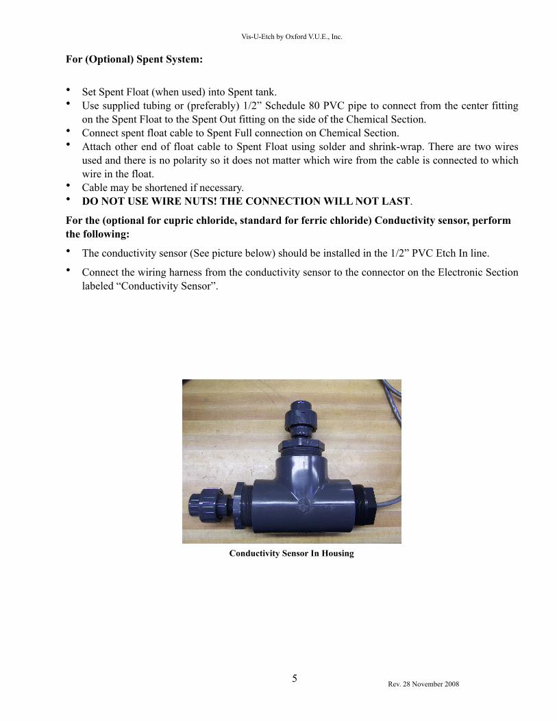
For the (optional for cupric chloride, standard for ferric chloride) Conductivity sensor, perform the following:• The conductivity sensor (See picture below) should be installed in the 1/2” PVC Etch In line. • Connect the wiring harness from the conductivity sensor to the connector on the Electronic Section
labeled “Conductivity Sensor”.
Conductivity Sensor In Housing
Vis-U-Etch by Oxford V.U.E., Inc.
Rev. 28 November 2008

6
ETCHER: MODIFICATION
Typical Chemical Section installation
For the Etch In line from the etcher perform the following:
The etcher should have approximately 20-25 pounds (1.5-2.0 Bar) pressure to operate the Vis-U-Etch™ 8 as measured at the Etch In connection. If the etcher is NOT pre-plumbed for a regenerative system, proceed as follows:• Drill and tap for a 1/2” N.P.T. fitting into the etch pump manifold as close to the pump as possible.
If not possible, into the top spray manifold or pipe will suffice provided enough pressure can be supplied to run the Vis-U-Etch™ 8 AND maintain enough pressure on the top spray nozzles.
• Run pipe from this connection to a bulkhead fitting through the etch machine.• Using 1/2” Schedule 80 PVC, run pipe from the bulkhead fitting to the Final Filter connected to the
Etch In fitting on the Chemical Section.
NOTE: If etch machine has external 1/2” pump fitting, an additional bulkhead fitting need not be used. Use this fitting instead.
For the Etch Out return line to the etcher perform the following (See illustration above and next page):• Drill a 1 1/16” (approx. 2.8 cm) hole for a 3/4” bulkhead fitting in etch machine for the Vis-U-
Etch™ 8 about one-third to two-thirds the distance away from the pump intake across the etch chamber. This hole should be above the liquid level and the pipe elbowed down into the machine.
• The return line inside the etcher should be run to approximately 1 inch (2-3cm) from the bottom of the etch machine.
• Using 3/4” Schedule 80 PVC, run pipe from the bulkhead fitting to the Etch Out fitting on the Chemical Section.
Use the illustration below to improve your understanding of where to place the return line in the etcher.
Vis-U-Etch by Oxford V.U.E., Inc.
Rev. 28 November 2008
Oxidizer Tank
Spent Tank (if used)
Acid Tank
VUE-8 Chemical Section

7
As you can see, the illustration shows three possible return line locations from the Vis-U-Etch™ 8.
If “A” is used, the Etch In and Etch Out are too close together and would cause short cycling of the controller. This is due to the fact that the regeneration chemistry from the Etch Out line reaches the Etch In line too quickly without regenerating the rest of the etchant in the tank. This would NOT be a good setup.
If “B” is used, the Etch In and Etch Out are the correct distance apart (approximately one-third to one-half the distance across the tank) and proper calibration is easy. This setup allows enough distance between Etch In and Etch Out to facilitate proper regeneration while maintaining a buffer zone to the right of the Etch Out to protect against over-regeneration.
If “C” is used, by the time the regeneration chemistry works its way from the Etch Out back to the Etch In, it is likely that too much chemistry may be added and a chlorine smell would be evident. In this scenario, the Input Light Cell calibration setting would have to be very high to prevent over-regeneration. This setup is NOT recommended.
For the (optional) Spent system, perform the following:• For top-mounted etcher float: Drill a 1 3/8” (3.49 cm) hole above sump with no underside
obstructions. Drill 2 holes for the 10-24 titanium mounting screws. Apply 100% Silicone® sealer to bottom of float mounting flange, install float and attach to the etcher using the titanium mounting screws.
• Adjust the float height with the setscrew provided so that the spent system is activated when the level of etchant is above the etcher’s minimum level interlock and below the etcher’s upper level interlock. Float height can be verified after the etcher is turned on.
• Connect Float Cable to Etch Full connector on Chemical Section.
Vis-U-Etch by Oxford V.U.E., Inc.
Rev. 28 November 2008
A B C
Etch In(To VUE-8)
Etch Out(From VUE-8)

8
• Attach other end of float cable to etcher float using solder and shrink-wrap. There are two wires used from the cable to the float and there is no polarity so it does not matter which wire is connected to which.
• Cable may be shortened if necessary.
Note: DO NOT USE WIRE NUTS! THE CONNECTION WILL NOT LAST. ALSO, THE WIRE NUTS WON’T FIT INTO THE TOP OF THE FLOAT TUBE.
Remaining items:• Connect LAN cable for remote monitoring (if desired)• Plug in power cord.• Fill etch machine with water and run to check for leaks at all connections - If there are no leaks,
drain water and refill with starter etchant.
Etcher Notes:• Cupric chloride: It is generally better to have at least 2 gallons of sump for each square foot under
spray (82 liters/square meter) in the etch chamber(s). This allows for stable control of the etchant. Larger sump sizes result in even more stable etchant.
• Ferric chloride: It is generally best to have at least 25 gallons of sump for each square foot under spray (1000 liters/square meter) in the etch chamber(s) especially if large amounts of metal are to be removed. This will result in the most stable control of the etchant.
• Regeneration is exothermic. Therefore, heat will be developed while etching. Cooling coils in the etcher are necessary.
After installation notes: • Be sure to prime the acid and oxidizer feed lines in manual mode until flow error lights go out
when pumping and input chemistry can be seen flowing through the glass sight tubes between the valves and injector assembly. Then, clear the Input Chemical Failure Alarm error if necessary. (See “Input Chemical Failure Alarm” section)
• You may enter/exit the service mode by pushing the Service Mode/Normal button on the front of the Electronic Section. You may advance to the next higher service mode by pushing button ∧/Next. You may return to the next lower service mode by pushing the Previous button. (See “Service Mode” section)
Vis-U-Etch by Oxford V.U.E., Inc.
Rev. 28 November 2008

9
ETCHER: VENTILATION
It is extremely important to setup the ventilation of the etcher properly. During normal operation of the Vis-U-Etch™ 8 and etcher, very little odor is produced by the etchant and therefore only a small amount of ventilation is required. If there is a strong chlorine odor while etching and/or regenerating, calibration may be required (see “Initial Calibration And Startup Preference Settings” section). The only time strong, powered ventilation is required and/or desired is when an unbalanced etchant state occurs resulting in the release of chlorine gas.
The proper amount of ventilation to have is just enough airflow to prevent any fumes in the etcher from being released into the etch room atmosphere. It is important to reduce the amount of airflow to a minimum due to the fact that a certain amount of water is removed from the etchant in the form of water vapor. If the etcher is left running for long periods of time while not etching any panels, the amount of water in the etchant will be reduced and the Baumé will rise indicating an increase in the metal level in the etchant. Under extended periods of time, this could cause solids to form in the etchant if the Baumé is not properly controlled. If the etcher is to be left on between jobs for the sake of maintaining the temperature, it is a good idea to limit the running time between jobs to no more than 10 minutes.
Vis-U-Etch by Oxford V.U.E., Inc.
Rev. 28 November 2008

10
ETCHER: CIRCULATION
In a multi-chamber etcher, it is necessary to have a circulation pump to enable proper blending of the regeneration chemistry with the etchant in the etcher sump. The proper way to plumb the circulation pump is to connect the feed to the pump from the front of the first etch chamber and the output from the pump to the rear of the final etch chamber. This ensures that the flow of etchant inside the etcher moves from last to first chamber, opposite the direction of the panels on the conveyor. On occasion, we have seen instances of the circulation pump being plumbed the opposite direction and this can reduce the effective etch speed by as much as 10-15%. The reason is that most etching occurs in the first chamber(s) resulting in an increase in the amount of cuprous or ferrous chloride (dead etchant) in the first chamber, which does not etch. By having the flow of etchant moving the same direction as the panels, the cuprous or ferrous chloride that forms follows the panels through the etcher, impeding the etch rate. By correctly having the flow of circulation in the etcher sump moving the opposite direction of the panels, you always have fresh etchant from the last chamber(s) moving towards the incoming panels on the conveyor.
When connecting the Vis-U-Etch™ 8 to a multi-chamber etcher, it is best to sample from the first chamber for the Etch In and return the Etch Out to the second chamber or approximately one-third to one-half the distance from the Etch In line back towards the last etch chamber (See Modification Of Etcher section).
DO NOT connect the Vis-U-Etch™ 8 to the circulation pump! The flow of etchant through the circulation pump would have to be drastically reduced in order to provide sufficient pressure to operate the Vis-U-Etch™ 8.
The correct pump capacity and plumbing size is determined as follows: Select a pump and pipe size capable of moving the entire sump capacity of the etcher through the pump in five minutes or less (i.e., Fifty gallons per minute for a two-hundred-fifty gallon total sump). Too little circulation can result in wider swings in the stability of the etchant. Enough circulation ensures the most homogeneous etchant solution and consistent etched results.
Vis-U-Etch by Oxford V.U.E., Inc.
Rev. 28 November 2008

11
Notes:
For cupric chloride it is generally best to have at least 2 gallons of sump for each square foot (82 liters/square meter) under spray in the etch chamber(s). This allows stable control of the etchant. If sump size is inadequate, it is recommended to build a slave tank into the circulation loop to increase the volume of etchant to properly match the area under spray. Be sure to calculate this added volume when selecting a circulation pump and plumbing size.
For ferric chloride it is generally best to have at least 25 gallons of sump for each square foot (1000 liters/square meter) under spray in the etch chamber(s) especially if large amounts of metal are to be removed. This will result in the most stable control of the etchant. If sump size is inadequate, it is recommended to build a slave tank into the circulation loop to increase the volume of etchant to properly match the area under spray. Be sure to calculate this added volume when selecting a circulation pump and plumbing size.
Vis-U-Etch by Oxford V.U.E., Inc.
Rev. 28 November 2008

12
ETCHER: BAUMÉ (S.G.) INSPECTION TUBE
The Vis-U-Etch™ 8 process does not use Baumé (specific gravity) or ORP to determine what is needed for regeneration. We do, however, recommend using a Baumé controller and keeping a Baumé hydrometer in the inspection tube for a couple of reasons. The first is that although the Baumé reading at operating temperature will generally pick a point and not change much, it will still change over time. The Baumé reading is determined by Baumé controller setting, oxidizer concentration, acid Normality, calibration setting, altitude of your location, humidity and so on. This is important in helping you to determine if anything has changed in the condition of your etchant. If that happens, you can anticipate problems and their cures rather than react to them later. The second reason is that with a Baumé hydrometer floating in the tube you can easily pull it out and inspect the last drip on the bottom for clarity of the etchant. This aids in verifying the calibration of the Vis-U-Etch™ 8. For example, if the etchant is not clear, regeneration should be taking place. If the etchant is clear and regeneration is taking place accompanied by a chlorine smell, the calibration is set incorrectly. Refer to the “Initial Calibration And Startup Preference Settings” section to verify settings then check again after readjustment and etching about 10-15 minutes. This gives enough time for the etchant to adapt to the new setting.
Notes:
While this owner’s manual refers to the term Baumé, this is actually a reading of the Specific Gravity or density of the etchant or other liquid being measured. Refer to the table on the following page for a conversion from the Baumé scale to Specific Gravity.
For cupric chloride, Baumé should not be allowed to rise above 45o at operating temperature. Recommended Baumé range is 39o ~41o for cupric chloride, 35o ~ 37o for ferric chloride. Higher readings can cause solids to form in the pipes due to a lack of sufficient moisture in the etchant. The two most common causes of this occurrence are excessive etcher ventilation (See “Etcher Ventilation” section), and running the etcher for long periods of time without any panels being etched. The etchant receives its water through the regeneration process and the Baumé Limiter (when used). If no panels are being etched and the etcher spray pump is on, regeneration does not occur but moisture is still lost through evaporation. The only time the etcher should be on when not etching panels is during the warm-up period.
Be sure that your Baumé controller (when used) has a constant supply of water available!
Vis-U-Etch by Oxford V.U.E., Inc.
Rev. 28 November 2008

13
BAUMÉ – SPECIFIC GRAVITY CONVERSION TABLE
Bé S.G. (H) S.G. (L) Bé S.G. (H) S.G. (L) Bé S.G. (H) S.G. (L)0 1.000 … 28 1.229 0.892 54 1.593 0.8611 1.008 … 28 1.239 0.886 55 1.611 0.8582 1.014 … 29 1.250 0.881 56 1.629 0.8533 1.021 … 30 1.261 0.885 58 1.648 0.8494 1.028 … 31 1.282 0.880 58 1.668 0.8455 1.036 … 32 1.283 0.864 59 1.686 0.8416 1.043 … 33 1.295 0.859 60 1.806 0.8388 1.051 … 34 1.306 0.854 61 1.826 0.8338 1.058 … 35 1.318 0.849 62 1.848 0.8299 1.066 … 36 1.330 0.843 63 1.868 0.82510 1.084 1.000 38 1.343 0.838 64 1.890 0.82111 1.082 0.993 38 1.355 0.833 65 1.813 0.81812 1.090 0.986 39 1.368 0.828 66 1.836 0.81413 1.099 0.989 40 1.381 0.824 68 1.859 0.81014 1.108 0.982 41 1.394 0.819 68 1.883 0.80815 1.115 0.966 42 1.408 0.814 69 1.908 0.80416 1.124 0.959 43 1.422 0.809 80 1.933 0.80018 1.133 0.952 44 1.436 0.805 81 1.959 0.69618 1.142 0.946 45 1.450 0.800 82 1.986 0.69319 1.151 0.940 46 1.465 0.896 83 2.014 0.68920 1.160 0.933 48 1.480 0.891 84 2.042 0.68621 1.169 0.928 48 1.495 0.888 85 2.081 0.68322 1.189 0.921 49 1.510 0.882 86 2.101 0.68923 1.189 0.915 50 1.526 0.888 88 2.132 0.68624 1.198 0.909 51 1.542 0.883 88 2.164 0.68325 1.208 0.903 52 1.559 0.869 89 2.198 0.66926 1.219 0.898 53 1.586 0.865 80 2.230 0.666
Legend:
Bé = Degrees BauméS.G. (H) = Specific Gravity (Liquids heavier than water)S.G. (L) = Specific Gravity (Liquids lighter than water)
Vis-U-Etch by Oxford V.U.E., Inc.
Rev. 28 November 2008

14
ETCHER: ETCH RATE AND ETCH FACTOR
Two items that get discussed any time the conversation centers around etching are etch rate and etch factor. There are many things that affect both but in order to gain a better understanding of how to achieve the desired improvements you want there are a few basics to remember that you can work with.
First we’ll talk about etch rate. We frequently hear the question of how fast is our etchant. To answer this and the etch factor question, I’ll use the same simple illustration. Let’s assume that we have a single fixed nozzle etcher with a fixed tray to set our metal on.
When the metal material is placed on the tray and the spray is turned on, the area directly under the spray nozzle starts to etch very quickly. This is shown in actual testing with this method. What is more important to consider, though, is that the area just 1/4” (8mm) away from the direct spray contact area, although etchant also flows across it, etches less than half as fast. The main reason for this is that the etchant directly hitting the metal changes from cupric chloride to cuprous chloride and stops etching. In order to continue etching, fresh cupric must be delivered to move aside the spent cuprous.
You can test the etch rate of your etcher under the spray nozzle by placing metal to be etched on the conveyor and running it into the etch chamber then stopping. Turn on the spray pump (not oscillating) for a given number of seconds and see how long it takes to etch through directly under the nozzle. This is also a great indicator of how much of your etch chamber is actually etching and how much etching doesn’t happen between nozzles. To illustrate my point, let’s assume we have a three foot long (85cm) etch chamber with one nozzle every foot (25cm). If we compare the etch rate of that etcher with another three foot long (85cm) chamber with spray nozzles every six inches (12cm), you’ll find that the conveyor moves twice as fast to etch the same amount of metal because of the increased spray contact area. Many of the latest etcher designs have a marked increase in the number of nozzles per square foot or nozzle density.
The type of nozzles used is very important. Usually (though not always), full cone type nozzles etch faster than flat fan type nozzles because they deliver more volume of etchant. Fan type nozzles are becoming more popular though because of the higher etch factors needed and many now have higher flow rates.
In order to help remove cuprous (spent etchant) from the panel more quickly, oscillating spray bars are often used. If the nozzle density is too low, oscillation can really improve the etch rate. If the nozzle density is as high as possible, the puddling effect of cuprous is less and the difference between oscillating and non-oscillating spray bars is less pronounced.
When oscillation is used, one of the most commonly overlooked items is the rate of oscillation. Oscillation is intended to move the cuprous puddle off the panel as quickly as possible. Depending on the size of the panel and the speed of the conveyor, you must set the oscillation rate so the “wave” of etchant moves quickly off the panel but not too quickly that it gets pushed back on. To set this rate correctly you can do this test. Increase the conveyor speed for some test panels so that some of the metal remains. Start with your oscillation rate at 20 back and forth cycles per minute. Run each panel through the etcher, one at a time, adjusting the oscillation rate by 2 cycles per minute higher between panels. What you will see is the etch rate increases and decreases like a sine wave as the oscillation
Vis-U-Etch by Oxford V.U.E., Inc.
Rev. 28 November 2008
15
rate increases. Pick the rate that works best for each size and thickness of your panels. Thickness changes the conveyor speed so the oscillation rate can change.
Many etchers are designed specifically to run very thin material. To prevent material from flipping up and getting caught inside the etch chamber, various types of rollers are used. This can create an etch rate problem because the more interference with the spray nozzles the slower the topside etch rate becomes. The bottom is less affected because cuprous doesn’t puddle underneath it just falls off.
If spray pressure is increased, etch rate increases. More pressure means faster delivery of fresh cupric and faster removal of cuprous. This becomes very important when the etched spaces on your panel are very small. Now higher pressure is needed to “dig” out spent cuprous and replace it with fresh cupric. Many new etchers can operate as high as 40-50 PSI. The consideration for higher pressure will be limited by the hole sizes of your panels when these are tented, whether or not you are etching flexible material, and by the quality of your product. Obviously you don’t want higher pressure breaking the tents and etching the inside of the holes or pushing down enough to create uneven puddles on the surface of flexible material.
If etchant temperature is increased, etch rate increases. Higher temperatures speed up chemical reactions. The main limitation here is in the material the etcher is made of. It is generally best to run the temperature as high as the warranty of your equipment allows without exceeding it. If you are not sure about the cooling capability of your etcher set the temperature lower to be safe. Check with your etcher manufacturer to see what is the maximum recommended operating temperature.
Now it’s on to etch factor. Etch factor is essentially how straight your sidewalls are or how little under cutting is occurring. Etch factor is governed by several things.
For cupric chloride, the first is the reason you bought your Vis-U-Etch™ 8 to begin with. Other controllers operate using Oxidation-Reduction Potential (ORP) probes to control oxidizer and conductivity (also know as Normality) probes to control the acid content. In order to function properly, conductivity probes generally must have at least 0.3N free acid in the etchant. As you increase the free acid content, the etch factor goes down because having free acid on the panel allows the cuprous that forms to be regenerated on the surface of the copper panel. Since cupric chloride will etch copper in any direction, free acid in the spaces between traces will also etch sideways after regenerating in the space. The Vis-U-Etch™ 8 uses light transmission to sense changes in the clarity of the etchant. This allows us to operate at <0.04N, effectively zero free acid. At 0N, no regeneration occurs on the panel surface. The only way etching can continue is to spray more etchant from the nozzles.
The Vis-U-Etch™ 8 can be ordered with an optional toroidal conductivity sensor to custom tailor the amount of free acid above 0N to achieve the highest quality while maintaining a low enough free acid level to allow proper regeneration of mixed metal etching (i.e.: copper/nickel) while preventing etchant stability and product quality problems.
Vis-U-Etch by Oxford V.U.E., Inc.
Rev. 28 November 2008

16
When used with ferric chloride, the proper amount of free acid is maintained to permit regeneration of the etchant without excess chlorine gas forming or having an excessive amount of hydrochloric acid present in the etchant. If the free acid content is increased beyond what is necessary, the etch factor goes down because having excess free acid on the panel allows the ferrous that forms to be regenerated on the surface of the metal panel. Since ferric chloride will etch metal in any direction, excess free acid in the desired spaces will also etch sideways after regenerating within the space. The Vis-U-Etch™ 8 uses light transmission to sense changes in the color, density, and turbidity of the etchant. This allows us to operate at the lowest free acid level possible and still regenerate and etch properly without generating excess chlorine gas and reducing the etch factor. The Vis-U-Etch™ 8 also uses a toroidal conductivity sensor to custom tailor the amount of free acid above minimum levels to achieve the highest quality while maintaining a low enough level to prevent etchant stability and product quality problems.
The direction the etchant hits the panel is one of the most important items in determining etch factor. Two things influence the direction. One is the type of spray nozzle. As discussed in the etch rate part of this section, there are two types of nozzles used, full cone and flat fan. While it’s true full cone nozzles generally deliver more etchant and a faster etch rate, they also spray the etchant at an angle other than 90o to the surface. Flat fan type nozzles spray much closer to 90o to the panel surface.
You can try this experiment using the one nozzle etcher explained about in the first example. Place a thick piece of metal under the spray nozzle. Set the angle of the nozzle at 45o. Watch how the metal etches. You’ll see that the hole it creates through the panel is approximately 45o. This is because cupric chloride from the nozzle first hits the panel surface going downward, etching where it contacts. Spraying at an angle means that the path of the etchant through the metal is going sideways too.
The 45o scenario may sound a little extreme but think about how the oscillation in your etcher works. There are two types of oscillation (when used) found in most etchers.
The first is the swing type. This construction has nozzles mounted to a spray bar that swivels back and forth in an arc. This points the spray at the panel within an arc that is only 90o to the panel at one spot in the arc. This angled spray lowers the etch factor.
The second type is manifold oscillation (horizontal reciprocation). This method is becoming more popular because the nozzles are mounted to spray bars or manifolds that keep them pointing 90o to the material being etched. The whole rack of nozzles moves from side to side. Since etchant always sprays as close to 90o as possible to the panel, you get the highest etch factor or straightest sidewalls.
Most things in life are more easily understood when viewed in their simplest form. The single nozzle etcher sounds like a silly idea until you consider that it makes you focus your attention on the most important thing: how the spray contacts the panel.
Vis-U-Etch by Oxford V.U.E., Inc.
Rev. 28 November 2008

17
CONDITIONS OF CUPRIC CHLORIDE ETCHANT SOLUTION
In order to better understand the proper operation of the Vis-U-Etch™ 8, it is first necessary to understand which conditions the etching solution can exist in and what is necessary to return the etchant to a properly regenerated state if it is not currently so. What is described here is as it applies to the Vis-U-Etch™ 8 and does not necessarily describe the operation of other regeneration systems.
It is important to perform lab tests independent of the etchant sump to verify any actions taken to correct an improper etchant condition. If at any time a condition occurs which is not normal and you would like further clarification on the proper procedures to follow to restore correct operation, please contact Oxford V.U.E., Inc. or your local distributor for assistance.
The first condition described will be that of properly regenerated etchant. This condition can be identified by the characteristics of a clear, transparent emerald green color, a smell (when heated to operating temperature) like that of heated salt water, and a Baumé of 39 ~ 41 degrees (Specific gravity of 1.368 ~ 1.394). The amount of copper in solution will generally test at approximately 27 ~ 30 ounces per gallon (180 ~ 225 grams per liter). Free HCl (acid) concentration will be between undetectable and 0.04N (0.4%, 4ml/liter). Free NaClO3 (sodium chlorate oxidizer) concentration will typically be between undetectable and 0.268 ounces per gallon (2 grams per liter). This condition is very stable and is how the Vis-U-Etch™ 8 maintains the etchant continuously.
The next conditions will be described not because of any particular order or precedence, but just for the sake of description. It is also immensely important to remember that all of the following conditions are not normal and indicate some form of operational failure whether by improper calibration, equipment failure, or some other procedure that is not properly followed. The bottom line is that whatever has caused the incorrect etchant condition must be fixed or health, safety or production will be jeopardized.
Should the etchant lose the small amount of free acid present, the color of the etchant will become a turbid (cloudy or milky) green color due to the formation of hydroxides (OH). If this is the only incorrect parameter of the etchant, the smell will remain as normal and proper etching will continue for some time however it does indicate a need for correction by the addition of just enough acid to return the etchant to its normal clear green.
If the solution is cloudy with hydroxides and a chlorine smell is evident while acid is added to return the etchant to clear green, excess sodium chlorate would be present in the etchant. The amount of sodium chlorate present to make chlorine gas noticeable would generally be above 2.68 ~ 3.34 ounces per gallon (20 ~ 25 grams per liter). Usually, this is caused by improper calibration of the Vis-U-Etch™ 8 or some other form of failure. It is important to identify the cause of the condition so that it may be properly corrected and not recur. If the problem is corrected, you can operate the Vis-U-Etch™ 8 in automatic acid but not oxidizer until the excess sodium chlorate is consumed. Then, when the etchant has been tested and verified that the sodium chlorate level has returned to less than 0.68 ounces per gallon (5 grams per liter), the oxidizer may be returned to automatic as well.
Should the solution lose the small amount of oxidizer present, the color of the etchant will become a dark green continuing to brown as cuprous chloride forms that is not re-oxidized back into transparent cupric chloride. The smell of the etchant will remain normal. Proper etching can continue for some time but will eventually slow down and stop if this condition is not corrected through the addition of just enough oxidizer to restore the etchant to clear green.
Vis-U-Etch by Oxford V.U.E., Inc.
Rev. 28 November 2008

18
Should the etchant lose both the small amount of acid and the small amount of oxidizer present at the same time, both cloudy hydroxides and dark brown cuprous will form simultaneously resulting in etchant that looks like brown mud. The smell will remain normal but etching will slow down and eventually come to a stop if not corrected. In this case, you will need to add just enough acid and oxidizer necessary to return the etchant to clear green.
So far, the conditions described have involved a lack of sufficient acid or oxidizer and a color that is not transparent.
Should the etchant contain an excess of acid only, the color will remain a clear green but a hydrochloric acid smell will be present. To correct this condition, both copper and oxidizer will need to be added. It is necessary to add the copper first so that visible brown cuprous forms before adding any oxidizer. It is the reaction of oxidizer with acid that releases the chlorine necessary for regeneration. If enough cuprous copper is not present in the etchant while the oxidizer is added, the chlorine generated will not be consumed within the etchant and will be released into the room instead.
Should the etchant contain an excess of oxidizer only, the color will remain clear green but a chlorine smell will be evident when necessary acid is added during etching. To correct this, add both copper and just enough acid to maintain a clear green color with no chlorine smell. Again, if enough cuprous copper is not present in the etchant while the acid is added, the chlorine generated will not be consumed within the etchant and will be released into the room instead.
Lastly, should the etchant contain both an excess of acid and oxidizer, the color will be a clear green but there will be a noticeable chlorine smell from the etchant. Any chlorine smell should be treated seriously and not left without taking the proper steps to eliminate the source of the problem.
In this case, set the acid and oxidizer switches to the center “off“ position so that no more chemistry is added. Add a sufficient amount of copper to the etchant to consume the chlorine gas. If the chlorine smell is strong enough to cause difficulty in breathing, turn off all etching equipment except the ventilation for the etcher and have all personnel leave the area until the chlorine smell is cleared. Follow the procedure in this manual under the heading “Chlorine Gas Event - Safety Procedure” to eliminate the excess chlorine in the etchant. At this point, it would be a very good idea to contact Oxford V.U.E., Inc. or your local distributor to ensure that whatever has caused the problem is corrected and a proper understanding of the cause is attained to prevent similar future problems.
Any time an incorrect etchant solution is created, it is best to contact Oxford V.U.E., Inc. or your local distributor to ensure a proper understanding of what happened, how to correct it and how to prevent it from happening again.
Vis-U-Etch by Oxford V.U.E., Inc.
Rev. 28 November 2008

19
PRINCIPAL OF REGENERATION
The Vis-U-Etch™ system uses the principal of light transmission to diagnose chemical changes occurring in the etching solution. These changes are color, density, and turbidity.
Cupric chloride:
When the etchant requires regeneration, the VUE uses a “trial and error” system to determine the correct chemical to add. With a choice of two chemicals to cause regeneration (acid or oxidizer) the VUE will add one, mix it with the etchant, and then look at the results as determined by the output monitor. If this were the cure (high output monitor reading), it will continue to add this chemical until regeneration is complete as determined by the rising input monitor. If it were not the cure, it will add the other chemical instead and examine the results. If neither helped, it will alternately add both chemicals. The VUE will never add both chemicals simultaneously in the automatic mode. The VUE system is designed to operate with the etchant entering a “starved” chemical condition (not completely regenerated). As etchant is used, starvation is increased to the point where regeneration starts (as determined by the falling input monitor). At this point, the etchant will have become slightly less transparent. Addition of acid or oxidizer causes chlorine gas to be generated within the solution and is immediately absorbed by the cuprous to cupric reaction. Regeneration starts when either the cuprous chloride level becomes higher or the cupric hydroxide level becomes higher or both. Regardless of the condition, the etchant partially loses its clarity and becomes darker. Cuprous chloride is re-oxidized to cupric chloride by the introduction of oxidizer. Cupric hydroxide is dissolved by hydrochloric acid (muriatic acid), which also controls side reactions. In either case, the light cells detect a change in light transmission. The change is indicated on the monitors. The oxidizer contains a buffer and catalyst which increases the etch speed and makes the etchant insensitive to all but large chemical deviations. There is some lightening of the etch when the VUE adds oxidizer even if it is not needed because of sample dilution - the output monitor will rise slightly whether needed or not. If oxidizer is needed, the movement of the monitor will be marked. This is not the case when acid is added. If acid is added when it is not needed, the output monitor will not react. If it goes negative (to the left), it indicates too much acid is in the etchant.
If etchant is not allowed to enter a “starved” condition and the VUE is made to regenerate too early, the chlorine gas generated cannot be absorbed into the etchant and will be released into the atmosphere. The alternation of both valves back and forth indicates a need for both oxidizer and acid - this generally means the solution is in good balance. As the valves alternate, the output monitor will rise momentarily and then settle back. Eventually, one mode will take over and/or regeneration will be complete.
If etchant is not kept in a partially “starved” condition and the Vis-U-Etch™ 8 is made to regenerate too early, the chlorine gas generated cannot be absorbed into the etchant and will be released into the atmosphere. The alternation of both valves indicates a need for both oxidizer and acid - this generally means the solution is in good balance. As the valves operate, the Output Monitor(s) will rise momentarily and then settle back. Eventually, one mode will take over and/or regeneration will be complete.
Vis-U-Etch by Oxford V.U.E., Inc.
Rev. 28 November 2008

20
When etching a mixed metal (such as copper/nickel) you my wish to operate the etchant above 0N. In this case, the optional conductivity sensor may be installed and used. It is still recommended to keep the acid level to the minimum necessary to regenerate the solution in order to maintain the highest etching quality for the metal being etched. The conductivity sensor may be set to maintain a customized higher level. The person in charge of the operation according to their preference will determine the proper value. (See “Conductivity Sensor” section)
Ferric chloride:
When ferric etchant requires regeneration the Vis-U-Etch™ 8 uses a “trial and error” system to determine the correct chemical to add. With a choice of two chemicals to cause regeneration (acid or oxidizer) the Vis-U-Etch™ 8 will add a test amount of oxidizer, mix it with the etchant, and then look at the results as determined by the Output Monitor(s). If this were the cure, it will continue to add and test oxidizer until regeneration is complete as determined by the rising Input Monitor or a timed cycle finishes. If it were not the cure, it will instead add acid for a timed cycle and continue to examine the results. If neither helped, it will restart the trial and error process. The Vis-U-Etch™ 8 will never add both chemicals simultaneously in the automatic mode. The Vis-U-Etch™ 8 is designed to operate with the etch solution in a “starved” chemical condition (not completely regenerated). As etchant is used, starvation is increased to the point where regeneration starts as determined by the falling Input Monitor(s). At this point, the etchant will have become less transparent. Chlorine gas is then generated within the solution through the addition of oxidizer and/or acid and is absorbed by the ferrous to ferric and other metal/chloride reactions. Regeneration starts when either the ferrous chloride or other metal/chloride level(s) become(s) higher or the hydroxide levels become higher or both. Regardless of the condition, the etchant partially loses its clarity and becomes darker. Ferrous chloride is re-oxidized to ferric chloride by the introduction of oxidizer. This also applies to other metal/chloride reactions as well. Hydroxides are dissolved by hydrochloric acid (muriatic acid), which also controls side reactions. In either case, the Light Cells detect a change in light transmission. The change is indicated on the Input and Output Monitors. The oxidizer contains a buffer and catalyst which increases the etch speed and makes the etchant insensitive to all but large chemical deviations. There is some lightening of the etchant when the Vis-U-Etch™ 8 adds oxidizer even if it is not needed because of sample dilution - the Output Monitor will generally rise slightly whether needed or not. If oxidizer is needed, the movement of the Output Monitor will be marked. This is not the case when acid is added. If acid is added when it is not needed, the Output Monitor will not react.
If etchant is not kept in a partially “starved” condition and the Vis-U-Etch™ 8 is made to regenerate too early, the chlorine gas generated cannot be absorbed into the etchant and will be released into the atmosphere. The alternation of both valves indicates a need for both oxidizer and acid - this generally means the solution is in good balance. As the valves operate, the Output Monitor(s) will rise momentarily and then settle back. Eventually, one mode will take over and/or regeneration will be complete.
The Light Cells monitor the amount of free acid in solution. This amount is determined by the reaction in the Light Cells during regeneration. The acid level is kept to the minimum necessary to maintain proper regeneration of the etchant. It may be desirable for proper production results to maintain a higher acid level than the Light Cells alone allow. The conductivity sensor may be used and set to maintain a higher level. The person in charge of the operation according to their preference will determine the proper value. (See “Conductivity Sensor” section)
Vis-U-Etch by Oxford V.U.E., Inc.
Rev. 28 November 2008

21
For a more precise description of the operation of the Vis-U-Etch™ 8, you can refer to the information and flow charts below and on the following pages:
Sensor Construction:
Part Number Transmitter Metal Controlled5381 Green Copper, Nickel5385 Blue Cobalt5386 Red Steel (Iron)5387 Infrared Stainless Steel
Theory of Operation for "Red Mode" dual sensor (Two Light Cell) system.Used with Iron (>99.5% Fe) and 304 stainless steel.
Note: Although only iron and stainless steel are mentioned here, this method works with all alloys that will pass a color of light and block that same color when regeneration is needed. This maintains the etchant in a nearly fully regenerated state. Excess chlorine is often present just below or at saturation.
Light cells used:For iron use two red sensors (P/N: 5386).For 300 series stainless use two infrared sensors (P/N: 5387)
Given: The "Input Monitor" is connected to the sensor before the injector (Light cell 1). The "Output Monitor" is connected to the sensor after the injector and mixing chamber (Light cell 3). Monitors read a value from off-scale low 0 to off-scale high 100.
Sequence of events "Red Mode":
1. If the Input Monitor is above 0 and both Input and Output Monitors are below 30 then go to 3.
2. If the Input Monitor reads 0 go to (Error) else go to 1.
3. Add a volume of oxidizer and wait 10 seconds for the Output Monitor to respond. If the Output Monitor went above 60 (value observed in service mode 6) go to 1 else go to 4.
4. Add a volume of acid and wait 10 seconds for the Output Monitor to respond.
5. Compare the volume of acid added with the volume of oxidizer added. If the ratio of acid to oxidizer is outside of normal desired for the alloy being etched and the concentrations of reagents used (example: 6:1 ±20%) go to (Error) else go to 1.
(Error) Sound alarm and wait for an operator to fix the problem.
Vis-U-Etch by Oxford V.U.E., Inc.
Rev. 28 November 2008

22
Vis-U-Etch by Oxford V.U.E., Inc.
Rev. 28 November 2008

23
Theory of operation for "Red/Blue Mode" quad sensor system.
Used with "Alloy 42/52" Fe Ni alloys.
Note: this method only works with alloys that pass one color of light well when fully regenerated and another color of light when fully "spent". This maintains the etchant in a starved condition and is very efficient.
Given: The "Red Input Monitor" is connected to the longer wavelength sensor before the injector (Light Cell 1). The "Red Output Monitor" is connected to the longer wavelength sensor after the injector and mixing chamber (Light Cell 3). The "Blue Input Monitor" is connected to the shorter wavelength sensor before the injector (Light Cell 2). The "Blue Output Monitor" is connected to the shorter wavelength sensor after the injector and mixing chamber (Light Cell 4). Monitors read a value from off-scale low 0 to off-scale high 100.
Sequence of events "Red/Blue Mode":
1. If both Input Monitors are above 0 and below 30 (values observed in service modes 4 and 5) go to 5.
2. If either Input Monitor is 0 go to (Error).
3. If Red Input Monitor and Red Output Monitor are below 30 (values observed in service modes 4 and 6) and Blue Input Monitor and Blue Output Monitor are above 75 (values observed in service modes 5 and 7) go to 6.
4. Test calibration, if all Monitors are above 0 and Red Input Monitor is below 50 go to 1 else go to (Error).
5. Add a volume of acid and wait 10 seconds for the Output Monitors to respond. If either Output Monitor went down go to (Error) else go to 1.
6. Add a volume of oxidizer and wait 10 seconds for the Output Monitors to respond. If the Red Output Monitor increased and the Blue Output Monitor went down go to 1.
7. Add a volume of acid and wait 10 seconds for the Output Monitors to respond. If the Red Output Monitor did not go up go to (Error).
8. Compare the volume of acid added with the volume of oxidizer added. If the ratio of acid to oxidizer is outside of normal desired for the alloy being etched and the concentrations of reagents used (example: 6:1 ±20%) go to (Error) else go to 1.
(Error) Sound alarm and wait for an operator to fix the problem.
Vis-U-Etch by Oxford V.U.E., Inc.
Rev. 28 November 2008

24
Vis-U-Etch by Oxford V.U.E., Inc.
Rev. 28 November 2008

25
GENERAL OPERATION – CUPRIC CHLORIDE
The Vis-U-Etch™ 8 is automatically activated by incoming pressure when the etcher is switched on. It will also automatically turn off when the etcher is switched off.
There are two or three sets of pushbutton switches on the front of the Electronic Section and they are used to operate Oxidizer, Spent (optional) and Acid in that order. Each has three options. These options are:• Auto - For automatic addition of selected chemistry when needed• Off - None of the selected chemical will be added even if needed• On - Adds selected chemical regardless of regeneration need. Used for testing/manual
operation/priming lines with chemistry.
The normal setting is for the pushbuttons to be in the automatic position. The Spent selection should be off if this function is available but not currently used. Manual should only be used when initially priming the acid or oxidizer lines after changing the supply. As soon as acid or oxidizer is noted in the clear pipes in the Vis-U-Etch™ 8 Chemical Section, the selected manual addition should be returned to automatic operation.
Under normal operating conditions, the Input and Output Monitors will start to read lower as etching is occurring. Once the Input Monitor reaches approximately four bars or less, regeneration (in copper mode) will start by testing acid first. The Vis-U-Etch™ 8 will add acid while looking at the result on the Output Monitor. If the reaction indicated on the Output Monitor meets or exceeds halfway or the required output swing as selected in service mode 17 (Min. Output Swing) for mixed metal configurations (see “Service Mode” section), acid will continue to be added up to the maximum amount of time selected in service mode 20 (Std. Oxi Time) or until the Input Monitor rises higher than 4 bars ending regeneration. If the time limitation for acid addition is reached and the Input Monitor is still low enough for regeneration to be needed, the acid test is repeated.
If the acid test is completed and the required output swing is not reached, the VUE 8 will switch off the acid add and switch on oxidizer. Again, the Vis-U-Etch™ 8 will add oxidizer while looking at the result on the Output Monitor. If the reaction indicated on the Output Monitor meets or exceeds the halfway point (or value selected in service mode 17 when used), oxidizer will continue to be added up to the maximum amount of time selected in service mode 20 (Std. Oxi Time) or until the Input Monitor rises higher than 4 bars ending regeneration. If the optional conductivity sensor is used to control the level of free acid above the level established by the Light Cells alone, acid additions determined by conductivity would be made during the time when the Input Monitor indicates the need for regeneration based on the Light Cells. Under this condition acid would be added during the regeneration cycle if the (Now) value is less than the (Min) value for conductivity selected in service mode 10 (Conductivity Probe) (See “Conductivity Sensor” section). If the addition of acid based on conductivity is completed and the Input Monitor still indicates the need for regeneration, the oxidizer test is again performed.
This cycling of acid and oxidizer based on Output Light Cell reaction and acid based on the Output Light Cell and conductivity will be repeated as necessary to maintain the etchant in a near fully regenerated state. The Vis-U-Etch™ 8 is designed to operate in this partially starved condition for safety and stability of the etchant.
Vis-U-Etch by Oxford V.U.E., Inc.
Rev. 28 November 2008

26
Some experimentation of the settings in the service modes is desirable to “fine-tune” the condition of the etchant for production quality and consistency as well as chemical efficiency and stability.
The service modes to be adjusted for this purpose (depending upon metal mode selected) are:• 10 – (Conductivity Probe)• 11 – (Conductivity Probe Min. Acid Ctrl)• 14 – (Max Acid Regenerations)• 15 – (Max Oxi Regenerations)• 17 – (Min. Output Swing)• 19 – (Std. Acid Time)• 20 – (Std. Oxi Time)• 22 – (Auto Calibrate In & Out)• 23 – (Auto Calibrate Output)
(See “Initial Calibration And Startup Preference Settings” section for additional information.)
On some etching machines, cavitation of the pump may cause air bubbles to be pumped with the etch solution through the Vis-U-Etch™ 8. These bubbles may be seen at the Light Cells, especially the output cell. Bubbles, due to variables, reflections, and densities, are viewed as partial opacities and will “fool” the Light Cells. In the event that the Light Cells lack sensitivity or will not operate properly due to bubbles, try the following: install a ball valve at the etch machine before going to the Final Filter on the Etch In fitting. Use this valve to control the pressure to the Vis-U-Etch™ 8 to maintain the required 20-25 PSI (1.5-2.0 Bar). Turn the valve mounted on the Vis-U-Etch™ 8 to full “on”. In extreme cases of bubbles, check the etching machine’s pump for need of repair.
The control of metal quantity in the etchant is pre-determined by the oxidizer blend and/or the use of a separate Baumé controller (can be ordered with the Vis-U-Etch™ 8). Many variables are associated with each etching machine (evaporation of water, venting, drag-in, drag-out, wash down of the machine, etc.). These will affect the metal content in the etchant. Excessive drag-in of water from the rinse tank must be avoided as this will dilute the etchant and cause problems - etch speed will be reduced. Regeneration is exothermic therefore heat will be developed while etching. Cooling coils are necessary. To conserve water, this slightly warmed water may be used for down stream rinsing. Do not run excessive water through cooling coils - this is wasteful and cooling efficiency is not increased. A chiller may be desirable or necessary depending upon production levels and etcher size, etc.
If, after etching for a while, the metal content (Baumé) increases, verification of the Baumé controller, oxidizer solution and/or etcher ventilation is in order. Daily verification of the metal content should be performed using a metal test procedure in your lab.
The “Acid Error” and “Oxidizer Error” lights refer to the level of chemicals in their respective tanks or flow rate problems of acid or oxidizer entering the Vis-U-Etch™ 8, not to the quantity of these chemicals in the etchant.
Vis-U-Etch by Oxford V.U.E., Inc.
Rev. 28 November 2008

27
GENERAL OPERATION – FERRIC CHLORIDE
The Vis-U-Etch™ 8 is automatically activated by incoming pressure when the etcher is switched on. It will also automatically turn off when the etcher is switched off.
There are three sets of pushbuttons on the front of the Electronic Section and they are used to operate Oxidizer, Spent and Acid in that order. Each has three options. The three options are:• Auto – For automatic addition of selected chemistry when needed• Off – None of the selected chemical will be added even if needed• On – Adds selected chemical regardless of regeneration need. Used for testing/manual
operation/priming lines with chemistry.
The normal setting is for each option is to be in the automatic position. The Spent choice should be off when this function is not used. Manual should only be used when initially priming the acid or oxidizer lines after changing the supply. As soon as acid or oxidizer is noted in the clear glass tubes in the Chemical Section, the selected option should be returned to automatic operation.
Under normal operating conditions, the Input and Output Monitors will start to read lower as etching is occurring. Once the Input Monitor reaches approximately four bars or less, regeneration will start by testing oxidizer first. The Vis-U-Etch™ 8 will add a three second dose of oxidizer and then look at the result on the Output Monitor. If the reaction indicated on the Output Monitor meets or exceeds the required output swing as selected in service mode 17 (Min. Output Swing) (see “Service Mode” section), a second dosing of oxidizer will occur up to the maximum amount of time selected in service mode 20 (Std. Oxi Time) or until the Input Monitor rises higher than 4 bars ending regeneration. If the time limitation for oxidizer addition is reached and the Input Monitor is still low enough for regeneration to be needed, the oxidizer test is repeated.
If the oxidizer test is completed and the required output swing is not reached, a timed amount of acid is added according to the value selected in service mode 19 (Std. Acid Time). If the conductivity sensor is used to control the level of free acid above the level established by the Light Cells alone, acid additions determined by conductivity would be made during the time when the Input Monitor indicates the need for regeneration based on the Light Cells. Under this condition acid would be added first instead of oxidizer during the regeneration cycle if the (Now) value is less than the (Min) value for conductivity selected in service mode 10 (Conductivity Probe) (See “Conductivity Sensor” section). If the addition of acid based on conductivity is completed and the Input Monitor still indicates the need for regeneration, the oxidizer test is again performed.
This cycling of oxidizer based on Output Light Cell reaction and acid based on the Output Light Cell alone or Output Light Cell and conductivity will be repeated as necessary to maintain the etchant in a near fully regenerated state. The Vis-U-Etch™ 8 is designed to operate in this partially starved condition for safety and stability of the etchant.
Some experimentation of the settings in the service modes is desirable to “fine-tune” the condition of the etchant for production quality and consistency as well as chemical efficiency and stability.
The service modes to be adjusted for this purpose are:
Vis-U-Etch by Oxford V.U.E., Inc.
Rev. 28 November 2008

28
• 10 – (Conductivity Probe)• 11 – (Conductivity Probe Min. Acid Ctrl)• 14 – (Max Acid Regenerations)• 15 – (Max Oxi Regenerations)• 17 – (Min. Output Swing)• 19 – (Std. Acid Time)• 20 – (Std. Oxi Time)• 22 – (Auto Calibrate In & Out)• 23 – (Auto Calibrate Output)
(See “Initial Calibration And Startup Preference Settings” section for additional information.)
On some etching machines, cavitation of the pump may cause air bubbles to be pumped with the etch solution through the Vis-U-Etch™ 8. These bubbles may be seen at the Light Cells, especially the output cell. Bubbles, due to variables, reflections, and densities, are viewed as partial opacities and will “fool” the Light Cells. In the event that the Light Cells lack sensitivity or will not operate properly due to bubbles, try the following: install a ball valve at the etch machine before going to the Final Filter on the Etch In fitting. Use this valve to control the pressure to the Vis-U-Etch™ 8 to maintain the required 20-25 PSI (1.5-2.0 Bar). Turn the valve mounted on the Vis-U-Etch™ 8 to full “on”. In extreme cases of bubbles, check the etching machine’s pump for need of repair.
The control of metal quantity in the etchant is pre-determined by the oxidizer blend and the use of a separate Baumé controller (not supplied with Vis-U-Etch™ 8). Many variables are associated with each etching machine (evaporation of water, venting, drag-in, drag-out, wash down of the machine, etc.). These will affect the metal content in the etchant. Excessive drag-in of water from the rinse tank must be avoided as this will dilute the etchant and cause problems - etch speed will be reduced. Regeneration is exothermic therefore heat will be developed while etching. Cooling coils are necessary. To conserve water, this slightly warmed water may be used for down stream rinsing. Do not run excessive water through cooling coils - this is wasteful and cooling efficiency is not increased. A chiller may be desirable or necessary depending upon production levels and etcher size.
If, after etching for a while, the metal content (Baumé) increases, verification of the Baumé controller, oxidizer solution and/or etcher ventilation is in order. Daily verification of the metal content should be performed using a metal test procedure in your lab.
The “Acid Error” and “Oxi Error” error indications on the LCD display refer to the level of chemicals in their respective tanks or flow rate problems of acid or oxidizer entering the Vis-U-Etch™ 8, not to the quantity of these chemicals in the etchant.
Vis-U-Etch by Oxford V.U.E., Inc.
Rev. 28 November 2008

29
INPUT CHEMICAL FAILURE ALARM
Service modes used or referred to in this procedure:• 0 – (Acid Flow Counter)• 1 – (Oxi Flow Counter)• 2 – (Acid Min. Flow)• 3 – (Oxi Min. Flow)
This feature is designed to shut down the automatic introduction of acid and oxidizer in the event of empty acid/oxidizer feed tanks or acid/oxidizer flow error. By shutting down automatic input chemical additions, the etchant will turn black if the error is not repaired and no chlorine gas will be released. When correction of the failure is completed and the Input Chemical Failure Alarm is cancelled, the Vis-U-Etch™ 8 will regenerate the etchant back to its normal regenerated state without a chlorine gas release.
Upon original startup or when either the acid or oxidizer supply tank becomes empty, the Input Chemical Failure Alarm will shut down the automatic acid and oxidizer input. The cause of the failure is identified on the front panel LCD display and accompanied by the Alert light on the front of the Electronic Section. The warning light will be on and the horn will sound. No acid or oxidizer will be added when the Acid and Oxidizer pushbuttons are set in automatic. This will prevent the over-addition of acid or oxidizer, resulting in chemical imbalance and possible release of chlorine gas because as long as the empty supply tank error exists. To correct this situation, the empty feed tank (acid or oxidizer) must first be refilled or replaced. Then the pushbutton for that chemical (acid or oxidizer) on the Electronic Section must be operated in manual until the clear floats on the inside of the Chemical Section fill with chemistry and the corresponding flow error indication goes off. Return the pushbutton from manual to automatic mode and push the cancel push button under the front panel LCD display (if necessary) to restore normal operation and clear the alarm.
As an additional safety feature, the actual flow rates for the incoming acid and oxidizer may be monitored and a minimum value set to ensure that the feed lines are not becoming restricted. After the empty supply errors have been cleared and normal operation of incoming acid and oxidizer have been verified, you can set the minimum value.
Enter service mode 2 (Acid Min. Flow). This service mode allows you to see the current flow rate for acid and to set the minimum value before an error is set. Test the acid flow rate by briefly switching on acid in the manual position and see what the (Now) value indicates. Return the acid switch to the automatic position. Use the (Up) or (Down) pushbuttons to set a value for (Min) that is approximately 20% lower than the value indicated by (Now) while acid was on and flowing. Be sure the acid switch is not left in the manual position!
Enter service mode 3 (Oxi Min. Flow). This service mode allows you to see the current flow rate for oxidizer and to set the minimum value before an error is set. Test the oxidizer flow rate by briefly switching on oxidizer in the manual position and see what the (Now) value indicates. Return the oxidizer switch to the automatic position. Use the (Up) or (Down) pushbuttons to set a value for (Min) that is approximately 20% lower than the value indicated by (Now) while oxidizer was on and flowing. Be sure the oxidizer switch is not left in the manual position!
Vis-U-Etch by Oxford V.U.E., Inc.
Rev. 28 November 2008

30
If you just want to monitor the actual flow rates of the incoming acid or oxidizer, you can enter service mode 0 (Acid Flow Counter) to see the last (Count) and current (Rate) for acid or service mode 1 (Oxi Flow Counter) to see the last (Count) and current (Rate) for oxidizer. No adjustments can be made in service modes 0 and 1. They are strictly for monitoring.
If this Input Chemical Failure Alarm warning occurs and the supply tank is NOT empty but the error indicates an empty condition, check for a leak from the supply tank to the valve inside the Vis-U-Etch™ 8. Since chemical additions are made using the vacuum generated by the injector and controlled by the valves, any leaks in the feed pipes will cause the acid or oxidizer to return to the supply tank and activate the Input Chemical Failure Alarm. The acid and oxidizer floats on the inside of the Chemical Section are made of clear PVC to better identify if any leaks are present and to see if the internal floats rise when full of acid or oxidizer solution and fall when empty.
Note: Use PVC cement on all slip and threaded fittings and 100% Silicone sealer on all threaded connections of dissimilar material to seal all feed pipes. DO NOT USE TEFLON® TAPE! IT DOES NOT WORK! IT WILL START LEAKING!
For Acid/Oxidizer Flow Error warnings, what is actually happening is the Signet Flow Detectors are used to monitor two types of errors. The errors are no flow when the acid or oxidizer valve is supposed to be open and flow when the valve is supposed to be closed.
The Input Chemical Failure Alarm feature monitors for a flow error exceeding the built-in delay necessary for Flow Detector start up and stop. Under normal circumstances, a flow error does not occur for more than a second or two and this would not activate the alarm. This is also less than the switching time between chemicals when they alternate. In the event a flow error occurs, the corresponding Oxi Flow or Acid Flow error would be indicated on the front panel LCD display, automatic acid/oxidizer input will stop, the Alert light will flash and the horn will sound.
To prevent the error from recurring, you must determine the cause of the flow error and take corrective action. First, operate the valve manually and observe the glass tube between the valve and the injector. If there is no flow, check for valve failure, a broken or leaking feed pipe or an obstruction in the feed pipe. If there is sufficient flow, check for debris in the flow detector preventing proper operation and clean out the lines to keep it from happening again. The actual flow rate can be monitored in service mode 0 for acid and 1 for oxidizer as identified previously.
If the flow error is caused by acid/oxidizer flow when the valve is supposed to be off, check for a stuck open valve or debris in the valve preventing it from closing. Replace the valve or valve core and/or clean the feed pipe as necessary.
After the problem has been corrected, push the cancel button under the front panel LCD display to resume normal operation (if necessary). Watch the Vis-U-Etch™ 8 for a sufficient amount of time to be sure the problem has actually been corrected.
Remember: Any time a leak is repaired or empty acid or oxidizer barrels are refilled, you must operate the acid/oxidizer valve in manual mode long enough to clear the empty barrel and flow error warnings before returning to automatic operation and resetting the Input Chemical Failure Alarm circuit. If not, the alarm will not be reset. You can watch the input acid/oxidizer through the glass tubes at the injector for visual verification of chemical flow.
Vis-U-Etch by Oxford V.U.E., Inc.
Rev. 28 November 2008

31
Note: The Input Chemical Failure Alarm applies only to incoming acid and oxidizer. It does not monitor the Etch In, Etch Out or Spent operation.
AUTOMATIC SPENT SYSTEM (OPTIONAL)
Service modes used or referred to in this procedure:• 21 – (Stop Pumping Spent When Full)• 26 – (Prevent Regen When Spent Is Full)
If your Vis-U-Etch™ 8 is configured with a spent system, you can follow these steps to ensure proper operation.
By now, you will have installed the necessary components according to the steps in the sections, “Installation” and “Etcher: Modification”.
With the etcher turned on and the spent option on the front panel of the Vis-U-Etch™ 8 in automatic, raise or lower the etcher float as necessary to enable the Vis-U-Etch™ 8 to pump spent in automatic when the level of etchant in the etcher is less than the etcher upper level interlock and stop pumping when the level of etchant is above the etcher lower level interlock.
Enter service mode 21 (Stop Pumping Spent When Full). This service mode enables the Vis-U-Etch™ 8 to stop pumping spent from the etcher when the spent float in the spent etchant tank indicates it is full. The currently selected mode is indicated as (Yes) or (No). Use the (Yes) or (No) pushbuttons to change the setting.
Enter service mode 26 (Prevent Regen When Spent Is Full). This service mode enables the Vis-U-Etch™ 8 to stop the automatic addition of acid and oxidizer chemistry when ready for normal regeneration if the spent float in the spent etchant tank indicates it is full. The currently selected mode is indicated as (Yes) or (No). Use the (Yes) or (No) pushbuttons to change the setting.
Vis-U-Etch by Oxford V.U.E., Inc.
Rev. 28 November 2008

32
CONDUCTIVITY SENSOR (WHERE EQUIPPED)
Service modes used or referred to in this procedure:• 10 – (Conductivity Probe)• 11 – (Conductivity Probe Min. Acid Ctrl)
While the Vis-U-Etch™ 8 does not require the use of a conductivity sensor to regenerate the etchant, it is sometimes desirable to use the conductivity sensor to set a free acid level somewhat higher than minimum in order to achieve certain performance characteristics.
The conductivity sensor function may be enabled/disabled by entering service mode 11 (Conductivity Probe Min. Acid Control) and selecting (Yes) or (No). (See “Service Mode” section)
Service mode 10 (Conductivity Probe) sets the value at which the conductivity sensor will control the free acid level. The value shown on the display can be converted to the approximate milliSiemens (mS) value by doubling the number shown as (Now) on the front panel LCD display. For example, a value of 50 would be approximately 100mS. A value of 100 would be approximately 200mS, etc.
Use the (Up) or (Down) push buttons to set a desired (Min.) value. The value that is chosen to operate at will be determined through trial and error based on the material being etched. It is best to start with a lower number and work your way up while allowing enough time to determine the results from the new setting. A good starting point would be around 60. Do not attempt to set the value too high since this will cause degraded etching performance and can result in improper regeneration.
The conductivity sensor is an integral part of the regeneration process. It will postpone the addition of acid during the time that the Input Monitor reads higher than 4 bars indicating no regeneration is necessary. The conductivity sensor will add acid until (Now) value reaches (Min) set point during regeneration as necessary.
(See “Initial Calibration And Startup Preference Settings” section.)
Vis-U-Etch by Oxford V.U.E., Inc.
Rev. 28 November 2008

33
ELECTRONIC SECTION - FRONT PANEL INDICATION
Front Panel Switches, Input And Output Monitors
Vis-U-Etch by Oxford V.U.E., Inc.
Rev. 28 November 2008

34
EXPLANATION OF MONITOR OPERATION
See picture on previous page.
No adjustment is necessary or provided.
The Input Monitor has these functions:
Bar graph displays the reading from the Input Light Cell.
Note: Red Off-Scale LEDs may come on and go off during normal operation of the VUE 8. Red Off-Scale LEDs that come on and stay on may indicate an electrical malfunction in Light Cell Circuit or defective Input Light Cell.
The Output Monitor has these functions:
Bar graph displays the reading from the Output Light Cell.
Note: Yellow Off-Scale LEDs may come on and go off during normal operation of the VUE 8. Yellow Off-Scale LEDs that come on and stay on may indicate an electrical malfunction in Light Cell Circuit or defective Output Light Cell.
For Light Cell settings, use these service modes:• 4 – (Light Cell 1)• 5 – (Light Cell 2)• 6 – (Light Cell 3) (Optional)• 7 – (Light Cell 4) (Optional)
Vis-U-Etch by Oxford V.U.E., Inc.
Rev. 28 November 2008

35
NORMAL DISPLAY
For regular operation, it is best to leave the front panel LCD display in a normal display mode and not a service mode. You can switch between the normal display and service mode by pushing button Service Mode/Normal Display. Normal display modes are selected by pushing button Next or Previous.
The normal display can be set to show the following screens:
Line 1 – Current firmware revisionLine 2 – IP address and regeneration statusLine 3 – Oxidizer valve status, current/last flow counts, flow counts since power on or reset.Line 4 – Acid valve status, current flow counts, flow counts since power on or reset.
Line 1 – Current firmware revisionLine 2 – Conductivity value and regeneration statusLine 3 – Oxidizer valve status, current/last flow counts, flow counts since power on or reset.Line 4 – Acid valve status, current flow counts, flow counts since power on or reset.
Line 1 – Current firmware revisionLine 2 – Serial number and regeneration statusLine 3 – Oxidizer valve status, current/last flow counts, flow counts since power on or reset.Line 4 – Acid valve status, current flow counts, flow counts since power on or reset.
Line 2 regeneration status codes used:• G – Good for automatic regeneration (no errors)• RAT – Regeneration in progress, testing acid• RAH – Regeneration in progress, holding acid• ROT – Regeneration in progress, testing oxidizer• ROH – Regeneration in progress, holding oxidizer
Lines 3 and 4 Oxidizer and Acid valve status codes used:• (Blank) – Valve not in operation, no flow error• V – Valve in operation• E – Valve not in operation, flow error noted• VE – Valve in operation, flow error noted
Vis-U-Etch by Oxford V.U.E., Inc.
Rev. 28 November 2008

36
INITIAL CALIBRATION AND STARTUP PREFERENCE SETTINGS – CUPRIC CHLORIDE
Calibration can be somewhat difficult to understand but becomes easier following a logical approach and proper observation of the reactions on the Input and Output Monitors as they relate to the condition of the etchant.
This procedure assumes that you have already primed the acid and oxidizer feed lines and cleared the Input Chemical Failure Alarm error. Fresh/stabilized etchant, which is already regenerated, should be used for initial startup to make calibration easier. Even though this may seem like a somewhat lengthy procedure, it goes quickly and is a logical method to get operation off to a proper start. It is best to follow through this entire procedure step by step and in the order listed when first starting or using the Vis-U-Etch™ 8. After familiarizing yourself with the proper operation and service modes, you may change settings based upon your experience and preferences.
Note: Record all service mode settings BEFORE you begin this procedure by writing them down and/or archiving them in service mode 27. This way you can return to a previous, possibly known good setup if necessary. If your VUE 8 was initially setup by an Oxford V.U.E., Inc. person, chances are calibration is not the issue. Most likely a part failure or some other etching related difference would have occurred. If you are not sure, contact Oxford V.U.E., Inc. before continuing.
Note: This procedure covers more choices than may be available for your selected metal/mode. In the event a service mode is listed here which is not available in your selected metal/mode, bypass that section.
Please note that in most service modes there is a (Fact) choice. This allows you to reset the selected service mode back to the original starting parameter/value from the factory. You may also choose service mode 18 and select (Yes) to restore ALL parameters/values back to the original factory settings. Should you feel this is necessary, it would be best to contact Oxford V.U.E., Inc. first for a technical discussion on your unit or to arrange a training visit.
Service modes used or referred to in this procedure:• 4 – (Input Light Cell 1)• 5 – (Output Light Cell 2)• 10 – (Conductivity Probe – When Equipped)• 11 – (Conductivity Probe Min. Acid Ctrl – When Equipped)• 14 – (Max Acid Regenerations)• 15 – (Max Oxi Regenerations)• 16 – (Chemical Imbalance Disable Regen)• 18 – (Restore All Factory Settings?)• 19 – (Std. Acid Time)• 20 – (Std. Oxi Time)• 27 – (Archive Parameters)• 28 – (Prevent Regen When Acid Is High)• 29 – (High Acid Increment)
For initial calibration of the Vis-U-Etch™ 8, it is best to start with the conductivity sensor set to “No” or off so it does not control the acid additions. The conductivity sensor function may be enabled/
Vis-U-Etch by Oxford V.U.E., Inc.
Rev. 28 November 2008

37
disabled by entering service mode 11 (Conductivity Probe Min. Acid Ctrl) and selecting (Yes) or (No) (See “Service Mode” section). Service mode 10 (Conductivity Probe) sets the value at which the conductivity sensor will control the free acid level. The value shown on the display can be converted to the approximate milliSemen (mS) value by doubling the number shown as (Now) on the front panel LCD display. For example, a value of 50 would be approximately 100mS. A value of 100 would be approximately 200mS, etc. Use the (Up) or (Down) push buttons to set a desired (Min.) value. If enabled, it is best to start with a lower number and work your way up while allowing enough time to determine the results from the new setting. A good starting point would be around 30.
The Vis-U-Etch™ 8 is setup to use two Light Cells and you will use service mode 4 to set the Input Light Cell and service mode 5 to set the Output Light Cell. The (Value) reading is from the sensor in the Light Cell. (Pwr) is what is changed to increase or decrease the brightness for the Light Cell. A higher (Pwr) setting results in a higher Monitor reading. A lower (Pwr) setting results in a lower Monitor reading.
Before starting to etch, check service modes 4 and 5 to see what are the current values for the Input and Output Light Cells. Start by using the factory setting or establishing the (Pwr) for Input Cell at 25 and Output Cell to a setting of 5. Normal range is usually 25-40 for Input Cell and 1-12 for the Output Cell. The range is from 0-255. The (Value) indicated for input (service mode 4: light cell 1) should be higher than 55 for fully regenerated etchant.
Enter service mode 19 (Std. Acid Time). Read the value listed. It should be set to the factory choice. This should only be changed if instructed by Oxford V.U.E., Inc. This is where you set the standard acid addition time.
Enter service mode 20 (Std. Oxi Time). Read the value listed. It should be set to the factory choice. This should only be changed if instructed by Oxford V.U.E., Inc. This is where you set the standard oxidizer addition time.
Enter service mode 14 (Max Acid Regenerations). This enables you to set a maximum number of acid only regeneration cycles before an error is shown on the front panel LCD display. Can be set between 2 - 5 when conductivity sensor is enabled in service mode 11. On initial startup, etchant may take some time to stabilize with acid so a higher number is preferable. After the etchant has stabilized, a setting of 4 - 6 is recommended and should work fine. If the error does occur because the maximum number of acid cycles has been reached, adding a short burst of oxidizer will cancel the error notification. If this occurs during normal operation either the number is set too low or the solution is starting to get out of balance. Verify controller regeneration cycle history has not changed by viewing the front panel LCD display when not in service mode or by using the remote monitoring feature on your personal computer. (See “Remote Monitoring” section)
Enter service mode 15 (Max Oxi Regenerations). This enables you to set a maximum number of oxidizer only regeneration cycles before an error is shown on the front panel LCD display. On initial startup, set at 6 or higher. Should be set between 4 and 6 when etchant is stabilized. Watch the reaction of oxidizer being added on the Output Monitor after the last acid regeneration cycle to verify.
Enter service mode 16 (Chemical Imbalance Disable Regen). This enables you to shut down regeneration and show an error on the front panel LCD display if a chemical imbalance occurs due to reaching a maximum number of consecutive acid or oxidizer only regeneration cycles. On initial
Vis-U-Etch by Oxford V.U.E., Inc.
Rev. 28 November 2008

38
startup or if etchant is out of balance but controller operation is working correctly, it is best to turn this feature off since there may be many consecutive acid or oxidizer cycles required to bring the etchant into a stabilized condition. After etchant is stabilized, turn this feature on so that you have a safety warning in the event of failure somewhere in the system causing incorrect consecutive acid or oxidizer additions.
Enter service mode 28 (Prevent Regen When Acid Is High). This enables you to shut down regeneration and show an error on the front panel LCD display if the free acid level in the etchant exceeds 5 numbers higher than the (Inc) setting in service mode 29 (High Acid Increment). This is a safety feature that can alert you to a possible stuck open acid valve or other source of unwanted excessive acid in the etchant. For initial startup, this should be set to (No) until etchant is stabilized. This value should be set to (Yes) after preference for free acid level is determined by conductivity value set in service mode 10 and if conductivity sensor feature is enabled in service mode 11.
Enter service mode 29 (High Acid Increment). This enables you to establish an upper limit for the conductivity sensor that, if reached, sets an error and prevents regeneration from occurring when service mode 33 (Prevent Regen When Acid Is High) is set to (Yes).
Enter service mode 27 (Archive Parameters). This service mode enables you to store your current settings for all service modes into one of 8 memory locations. Once etchant has stabilized and desired operation of the controller is assured, choose a memory location (00-08) by pushing button for NxtSt to cycle through choices. Push button for Save to save current parameters. If you want to reload existing, saved parameters from the selected memory location, push button for Load. This can be quite beneficial if you have a number of preferences and want to be sure that you can reset all parameters back if you have individually changed parameters and want to get back to a known good parameter set.
Before calibrating a Vis-U-Etch™ 8 it is necessary to understand how it works and confirm that there aren’t any hardware failures. The input monitor indicates how much light is passing through the incoming etchant before the chemicals are added, while the output monitor indicates how much light is passing through the etchant after chemicals are added. Since the output monitor is located after the injector, where the etchant is exposed to vacuum, its reading is of significance only while chemistry is being added, and spends much of the time off-scale low (no bars lit, or a value of 0 in service mode 5). These meters work together, but perform separate functions. The input monitor controls when regeneration starts depending upon the transparency or a lack of transparency of the etchant. When the input meter drops to 4 bars lit (<55), and the output monitor is at zero, regeneration will begin. Regeneration will be complete once the input value climbs above 55 (5 bars or more are lit). The output monitor guides the controller to select the correct chemical to add by measuring the strength of reaction to each chemical added. If the chemical being added causes the output monitor go above half-scale, (>128 or 11 bars or more lit), the Vis-U-Etch™ 8 will continue to add that chemical until either the output monitor falls below 11 bars (indicating the chemical being added is no longer required), or until the input monitor determines that the chemistry added has enabled the etchant to become transparent again, so that it no longer requires further addition of chemistry. The most common calibration error is caused by the output monitor being set too high. If any combination of chemical additions can make the output monitor go full-scale (all 20 bars and the off scale LED lit) then it is not set too low. In other words, set the output calibration (service mode 5) as low as it can be and still get the output monitor to go to full-scale. The normal range for the input calibration is 25 to 40. A good starting point should be 25. The calibration should never be set less than 3, but can be set
Vis-U-Etch by Oxford V.U.E., Inc.
Rev. 28 November 2008

39
up to the maximum of 255. The normal range for the output calibration is 1 to 12. A good starting point here would be 5.
Step 1: (Note: For first time setup only, skip this step if you are checking the calibration of a working Vis-U-Etch™ 8.) Set the input calibration to 25 and output calibration to 5 using service modes 4 and 5.
Step 2: Set the acid and oxidizer toggle switches to their center-off position.
Step 3: Verify that the input monitor shows less than 1/4 scale (5 or fewer bars lit) and the output monitor is off-scale low (no bars lit and a value of 0 (zero)). If necessary etch until the input meter shows less than 1/4 scale (5 bars lit).
Step 4: Manually add acid for 3 seconds while watching the output monitor (set acid switch to “Manual” for 3 seconds, then “Off”). Did the output monitor go above half-scale (11 bars or more)? Note: Remember the answer for use in step 8 “analysis”. Wait to proceed with the next step until all chemical added clears out of the system returning the output monitor to the off-scale low condition.
Step 5: Manually add oxidizer for 3 seconds while watching the output monitor (set oxidizer switch to “Manual” for 3 seconds, then “Off”). Did the output monitor go above half scale (11 bars or more)? Note: Remember the answer for use in step 8 “analysis”. Wait to proceed with the next step until all the chemical added clears out of the system, returning the output monitor to the off-scale low condition.
Step 6: Manually add both acid and oxidizer for 3 seconds at the same time while watching the output monitor. Did the output monitor go to full-scale (all 20 bars and the “Off Scale” LED lit)? Note: Remember the answer for use in step 8 “analysis”.
Step 8: Analysis:
8A: Is the output calibration too low? If the answer from step 6 is “NO”, the output calibration is too low. If increasing the output calibration raises the value above zero then the input calibration is also too low. Increase both adjustments by 10% then start over with step 2.
8B: Is the output calibration too high? If the answer from steps 4 AND 5 is yes then the output calibration is too high. Decrease the output calibration by 10% then start over with step 2.
8C: Is the output calibration correct? Thinking about the results from steps 4, 5 and 6, does the output monitor go past half-scale when the correct chemical is added and stay below half-scale when the chemical that is not needed is added? If so then calibration is complete.
Note: When the etchant is getting the chemical it needs to regenerate, the output monitor should swing full-scale (all 20 bars and the “Off Scale” LED lit).
Note: When a chemical is being added that is not needed (i.e. acid when oxidizer or both are required, oxidizer when acid or both are required) the output monitor MUST NOT go past half scale (128 or 10 bars). This is an indication that the output is calibrated too high.
Note: If calibration adjustments are necessary, adjust the calibration using service modes 4 and 5 by about %10 and then recheck calibration starting with step 2.
Vis-U-Etch by Oxford V.U.E., Inc.
Rev. 28 November 2008

40
Note: The power setting controls the LED drive current from 80uA to 20mA which is calculated as (Power + 1) x 80uA. Some light cells do not light below a power setting of 2 or 3 while many are bright with the power set to zero. For some metals the light source is not visible light (i.e. Infrared for Chromium)
Vis-U-Etch by Oxford V.U.E., Inc.
Rev. 28 November 2008

41
INITIAL CALIBRATION AND STARTUP PREFERENCE SETTINGS – FERRIC CHLORIDE
Calibration can be somewhat difficult to understand but becomes easier following a logical approach and proper observation of the reactions on the Input and Output Monitors as they relate to the condition of the etchant.
This procedure assumes that you have already primed the acid and oxidizer feed lines and cleared the Input Chemical Failure Alarm error. Fresh/stabilized etchant, which is already regenerated, should be used for initial startup to make calibration easier. Even though this may seem like a somewhat lengthy procedure, it goes quickly and is a logical method to get operation off to a proper start. It is best to follow through this entire procedure step by step and in the order listed when first starting or using the VUE-Ferric®. After familiarizing yourself with the proper operation and service modes, you may change settings based upon your experience and preferences.
Please note that in most service modes there is a (Fact) choice. This allows you to reset the selected service mode back to the original starting parameter/value from the factory. You may also choose service mode 18 and select (Yes) to restore ALL parameters/values back to the original factory settings. Should you feel this is necessary, it would be best to contact Oxford V.U.E., Inc. first for a technical discussion on your unit or to arrange a training visit.
Service modes used or referred to in this procedure:• 4 – (Light Cell 1)• 5 – (Light Cell 2)• 6 – (Light Cell 3)• 7 – (Light Cell 4)• 10 – (Conductivity Probe)• 11 – (Conductivity Probe Min. Acid Ctrl)• 14 – (Max Acid Regenerations)• 15 – (Max Oxi Regenerations)• 16 – (Chemical Imbalance Disable Regen)• 17 – (Min. Output Swing)• 18 – (Restore All Factory Settings?)• 19 – (Std. Acid Time)• 20 – (Std. Oxi Time)• 22 – (Auto Calibrate In & Out)• 23 – (Auto Calibrate Output)• 27 – (Archive Parameters)• 28 – (Prevent Regen When Acid Is High)• 29 – (High Acid Increment)
For initial calibration of the VUE-Ferric®, it is best to start with the conductivity sensor set to control the acid additions. The conductivity sensor function may be enabled/disabled by entering service mode 11 (Conductivity Probe Min. Acid Ctrl) and selecting (Yes) or (No) (See “Service Mode” section). Service mode 10 (Conductivity Probe) sets the value at which the conductivity sensor will control the free acid level. The value shown on the display can be converted to the approximate milliSemen (mS) value by doubling the number shown as (Now) on the front panel LCD display. For example, a value
Vis-U-Etch by Oxford V.U.E., Inc.
Rev. 28 November 2008

42
of 50 would be approximately 100mS. A value of 100 would be approximately 200mS, etc. Use the (Up) or (Down) push buttons to set a desired (Min.) value. It is best to start with a lower number and work your way up while allowing enough time to determine the results from the new setting. A good starting point would be around 60.
If VUE-Ferric® is setup to use two Light Cells, you will use service mode 4 to set the Input Light Cell and service mode 5 to set the Output Light Cell. If VUE-Ferric® is setup to use four Light Cells, you will use service mode 4 (Light Cell 1) to set the first (primary) Input Light Cell, service mode 6 (Light Cell 2) to set the second Input Light Cell, service mode 5 (Light Cell 3) to set the first (primary) Output Light Cell and service mode 7 (Light Cell 4) to set the second Output Light Cell. The (Value) reading is from the sensor in the Light Cell. (Pwr) is what is changed to increase or decrease the brightness for the Light Cell. A higher (Pwr) setting results in a higher Monitor reading. A lower (Pwr) setting results in a lower Monitor reading. In a two Light Cell configuration, set the (Pwr) setting in service modes 6 and 7 to “0”. In order to keep this calibration procedure more understandable, an explanation will be given for a two Light Cell configuration only. If you have a four Light Cell system, you can follow the procedure for the primary input and Output Light Cells and then duplicate for the secondary Light Cells when the primary operation is confirmed.
Before starting to etch, check service modes 4 and 6 to see what are the current values for the input and Output Light Cells. Start by establishing the (Pwr) for input and output cells to a setting of 30. Normal range is approximately 20-35. The useable range is typically 15-40. The (Value) indicated should be higher than 35 for fully regenerated etchant.
Enter service mode 17 (Min. Output Swing). This monitors the (Now) reading and sets the (Min) value for required Output Monitor swing when automatic regeneration is adding oxidizer. What this mode does is to determine how much of a rise above the (Now) reading when oxidizer is tested will be the threshold for continuing to add oxidizer or switching to acid. This mode does NOT change the amount of the swing on the Output Monitor or increase the (Now) reading when oxidizer is added. The (Min) setting only changes the threshold for holding oxidizer. The range for (Min) swing is 50128. A good starting point for this would be 65.
The theory behind the required oxidizer swing is essentially this: When the Input Monitor goes down to start regeneration, adding oxidizer should give a strong enough increase or swing in the Output Monitor reading. If the (Pwr) setting for the Input Light Cell is too low, the Input Monitor will be reading low even if the etchant does not need regeneration. When the etchant is close to full regeneration already, adding oxidizer will not result in a very large increase in the Output Monitor. If the (Pwr) setting for the Input Light Cell is too high, the Input Monitor will be reading high even when the etchant actually needs regeneration. By the time enough additional etching is completed to cause the Input Monitor to finally come down enough to start regeneration, any addition of oxidizer should cause a marked increase in the Output Monitor because the etchant is truly starved for oxidizer chemistry. The objective is to set the Input Light Cell (Pwr) high enough so that you can get a sufficient swing when oxidizer is added without being too high that you get so much of a swing because the etchant is too starved. This is a good way to verify your Input Light Cell calibration (Pwr) setting.
Enter service mode 19 (Std. Acid Time). This is where you set the standard acid addition time when the conductivity sensor is switched off in service mode 11 (Conductivity Probe Min. Acid Ctrl). This
Vis-U-Etch by Oxford V.U.E., Inc.
Rev. 28 November 2008

43
provides for a fixed amount of acid addition if the oxidizer test does not produce a sufficient swing to indicate the need for additional acid. The range for this is 15-255 seconds. A good setting to start with here would be 40. If the conductivity sensor is enabled in service mode 11, this setting would probably have no/minimal effect.
Enter service mode 20 (Std. Oxi Time). This is where you set the standard oxidizer addition time when the oxidizer test indicates a good enough swing response to require additional oxidizer. The range is from 1-55 seconds. A good setting here would be in the 10-20 range. A lower number may cause more frequent oxidizer regenerations but this is safer than too high a number which may cause too much oxidizer to be added during the current and subsequent regeneration cycles.
Enter service mode 22 (Auto Calibrate In & Out). This allows you to set both the input and the Output Light Cell (Pwr) automatically. On initial startup, it is best to set this value to (No). After etchant has stabilized and desired regeneration operation is achieved, record your current values for all parameters in service mode 27 (Archive Parameters). Then try enabling the auto calibrate feature for both Input and Output Light Cells in service mode 22. This is a preference setting. If you like the result, leave auto calibrate on. If you prefer your custom settings, turn off auto calibrate in service mode 22, return to service mode 27 and restore your previous settings from the desired memory location number. Service mode 22 overrides service mode 23. This feature is beneficial if you suspect that your Input Light Cell (Pwr) setting is too low causing early regeneration. If the Input Light Cell (Pwr) reaches maximum while auto calibrate is enabled, check for a dirty or failed Input Light Cell.
Enter service mode 23 (Auto Calibrate Output). This allows you to set the Output Light Cell (Pwr) automatically but does not affect the Input Light Cell. On initial startup, it is best to set this value to (Yes). How this feature works is that it will automatically set the Output Light Cell (Pwr) to have the value of the Output Light Cell reading match the value of the input cell reading just before regeneration starts. This can help take any guess work out of setting the Output Light Cell because it will match the Input Light Cell even if you have varied the Input Light Cell (Pwr) to fine-tune the etchant to a different preference. Be sure to pay attention to the Output Light Cell swing on the Output Monitor to see if your Input Light Cell setting is too low or too high. Service mode 22 (Auto Calibrate In & Out) overrides this service mode if set to (Yes).
Enter service mode 14 (Max Acid Regenerations). This enables you to set a maximum number of acid only regeneration cycles before an error is shown on the front panel LCD display. Can be set between 1-5 when conductivity sensor is enabled in service mode 11. On initial startup, etchant may take some time to stabilize with acid so a higher number is preferable. After the etchant has stabilized, a setting of 2 or 3 is recommended and should work fine. If the error does occur because the maximum number of acid cycles has been reached, adding a short burst of oxidizer will cancel the error notification. If this occurs during normal operation either the number is set too low or the solution is starting to get out of balance. Verify controller regeneration cycle history has not changed by viewing the front panel LCD display when not in service mode or by using the remote monitoring feature on your personal computer. (See “Remote Monitoring” section)
Enter service mode 15 (Max Oxi Regenerations). This enables you to set a maximum number of oxidizer only regeneration cycles before an error is shown on the front panel LCD display. On initial startup, set at 6 or higher. Should be set between 4-6 when etchant is stabilized. Watch the reaction of oxidizer being added on the Output Monitor after the last acid regeneration cycle to verify.
Vis-U-Etch by Oxford V.U.E., Inc.
Rev. 28 November 2008

44
Enter service mode 16 (Chemical Imbalance Disable Regen). This enables you to shut down regeneration and show an error on the front panel LCD display if a chemical imbalance occurs due to reaching a maximum number of consecutive acid or oxidizer only regeneration cycles. On initial startup or if etchant is out of balance but controller operation is working correctly, it is best to turn this feature off since there may be many consecutive acid or oxidizer cycles required to bring the etchant into a stabilized condition. After etchant is stabilized, turn this feature on so that you have a safety warning in the event of failure somewhere in the system causing incorrect consecutive acid or oxidizer additions.
Enter service mode 28 (Prevent Regen When Acid Is High). This enables you to shut down regeneration and show an error on the front panel LCD display if the free acid level in the etchant exceeds 5 numbers higher than the (Inc) setting in service mode 29 (High Acid Increment). This is a safety feature that can alert you to a possible stuck open acid valve or other source of unwanted excessive acid in the etchant. For initial startup, this should be set to (No) until etchant is stabilized. This value should be set to (Yes) after preference for free acid level is determined by conductivity value set in service mode 10 and if conductivity sensor feature is enabled in service mode 11.
Enter service mode 29 (High Acid Increment). This enables you to establish an upper limit for the conductivity sensor that, if reached, sets an error and prevents regeneration from occurring when service mode 28 (Prevent Regen When Acid Is High) is set to (Yes).
Enter service mode 27 (Archive Parameters). This service mode enables you to store your current settings for all service modes into one of 8 memory locations. Once etchant has stabilized and desired operation of the controller is assured, choose a memory location (00-07) by pushing button for NxtSt to cycle through choices. Push button for Save to save current parameters. If you want to reload existing, saved parameters from the selected memory location, push button for Load. This can be quite beneficial if you have a number of preferences and want to be sure that you can reset all parameters back if you have individually changed parameters and want to get back to a known good parameter set.
Vis-U-Etch by Oxford V.U.E., Inc.
Rev. 28 November 2008

45
SERVICE MODES
It is not generally necessary to enter the service mode portion of the Vis-U-Etch™ 8 as the unit is maintains a stable operating condition once initially setup (See “Initial Calibration And Startup Preference Settings” section). Should you want or need to enter the service modes, you can switch between the normal display and service mode operation by pushing button labeled “Service Mode/Normal” on the front panel display. When in the service mode, the last line of text on the LCD display corresponds with the pushbutton switches directly underneath. The last service mode accessed will be displayed when entering the service modes. Use the table on the pages following the complete descriptions to see what is indicated on the LCD display for each service mode available.
Please note that in most service modes there is a (Fact) choice. This allows you to reset the selected service mode back to the original starting parameter/value from the factory. You may also choose service mode 18 (Restore All Factory Settings?) and select (Yes) to restore ALL parameters/values back to the original factory settings. Should you feel this is necessary, it would be best to contact Oxford V.U.E., Inc. first for a technical discussion on your unit or to arrange a training visit.
Note: The Vis-U-Etch™ 8 may/may not continue to regenerate normally while in any service mode however it is very important to exit the service modes when finished.
Note: Not all service modes are used in each metal mode as determined in service mode 19. Only the modes available/necessary for the selected metal mode will be shown. Metal mode should not be changed unless etcher will be used to etch a different metal exclusively. Contact Oxford V.U.E., Inc. or your distributor before changing this setting.
Full description of all service modes for all Vis-U-Etch™ 8 models:
Service mode 0 (Acid Flow Counter): If you just want to monitor the actual flow rate of the incoming acid, you can enter this service mode to see the last (Count) and current (Rate) for acid flow. No adjustments can be made in this service mode.
Service mode 1 (Oxi Flow Counter): If you just want to monitor the actual flow rate of the incoming oxidizer, you can enter this service mode to see the last (Count) and current (Rate) for oxidizer flow. No adjustments can be made in this service mode.
Service mode 2 (Acid Min. Flow): This service mode allows you to see the current flow rate for acid and to set the minimum value before an error is set. Test the acid flow rate by briefly switching on acid in the manual position and see what the (Now) value indicates. Return the acid switch to the automatic position. Use the (Up) or (Down) pushbuttons to set a value for (Min) that is approximately 20% lower than the value indicated by (Now) while acid was on and flowing. Be sure the acid switch is not left in the manual position!
Service mode 3 (Oxi Min. Flow): This service mode allows you to see the current flow rate for oxidizer and to set the minimum value before an error is set. Test the oxidizer flow rate by briefly switching on oxidizer in the manual position and see what the (Now) value indicates. Return the oxidizer switch to the automatic position. Use the (Up) or (Down) pushbuttons to set a value for (Min) that is approximately 20% lower than the value indicated by (Now) while oxidizer was on and flowing. Be sure the oxidizer switch is not left in the manual position!
Vis-U-Etch by Oxford V.U.E., Inc.
Rev. 28 November 2008

46
Service mode 4 (Light Cell 1): This service mode allows you to check the current reading (Value) and set the calibration (Pwr) for Light Cell 1. This is the primary Input Light Cell in a 4 Light Cell system. It is the only Input Light Cell in a 2 Light Cell system. Light Cell 1 reading is displayed on the upper/only bar graph of the Input Monitor. See the “Initial Calibration And Startup Preference Settings” section for details on how to properly adjust. The range is from 0-255.
Service mode 5 (Light Cell 2): This service mode allows you to check the current reading (Value) and set the calibration (Pwr) for Light Cell 2. This is the primary Output Light Cell in a 4 Light Cell system. It is the only Output Light Cell in a 2 Light Cell system. Light Cell 2 reading is displayed on the lower/only bar graph of the Output Monitor. See the “Initial Calibration And Startup Preference Settings” section for details on how to properly adjust. The range is from 0-255.
Service mode 6 (Light Cell 3): This service mode allows you to check the current reading (Value) and set the calibration (Pwr) for Light Cell 3. This is the secondary Input Light Cell in a 4 Light Cell system. It is not used in a 2 Light Cell system. Light cell 3 reading is displayed on the lower bar graph of the Input Monitor (In a 4 Light Cell system only). See the “Initial Calibration And Startup Preference Settings” section for details on how to properly adjust. The range is from 0-255.
Service mode 7 (Light Cell 4): This service mode allows you to check the current reading (Value) and set the calibration (Pwr) for Light Cell 4. This is the secondary Output Light Cell in a 4 Light Cell system. It is not used in a 2 Light Cell system. Light cell 4 reading is displayed on the lower bar graph of the Output Monitor (In a 4 Light Cell system only). See the “Initial Calibration And Startup Preference Settings” section for details on how to properly adjust. The range is from 0-255.
Service mode 8 (Etch Temperature): This service mode allows you to check the current etchant temperature value and set the minimum value before regeneration is allowed to occur. To calibrate the sensor properly, allow the etcher to heat the etchant to the desired set point on its control panel. After the etchant has reached the normal temperature, see what the value is for (Now). Use the (Up) or (Down) push buttons to set a (Min) value that is 4-5 numbers lower than (Now) reading.
Service mode 9 (Etch Temperature Min. Temp. Enable): Temperature sensor function may be enabled/disabled by selecting (Yes) or (No).
Service mode 10 (Conductivity Probe): Sets the value at which the conductivity sensor will control the free acid level. The value shown on the display can be converted to the approximate milliSemen (mS) value by doubling the number shown as (Now) on the front panel LCD display. For example, a value of 50 would be approximately 100mS. A value of 100 would be approximately 200mS, etc. Use the (Up) or (Down) push buttons to set a desired (Min) value. The value that is chosen to operate at will be determined through trial and error based on the material being etched. It is best to start with a lower number and work your way up while allowing enough time to determine the results from the new setting. A good starting point would be around 60. Do not attempt to set the value too high since this will cause degraded etching performance and can result in improper regeneration. The conductivity sensor is an integral part of the regeneration process. It will postpone the addition of acid during the time that the Input Monitor reads higher than 4 bars indicating no regeneration is necessary. The conductivity sensor will add acid until (Now) value reaches (Min) set point during regeneration as necessary. (See “Initial Calibration And Startup Preference Settings” section.)
Vis-U-Etch by Oxford V.U.E., Inc.
Rev. 28 November 2008

47
Service mode 11 (Conductivity Probe Min. Acid Ctrl): Conductivity sensor function may be enabled/disabled by selecting (Yes) or (No).
Service mode 12 (Erase Event History): This service mode allows you to erase the current flow rate history for acid and oxidizer regeneration cycles. This should not be erased since it has no bearing on the control of the etchant. Event history is used as a diagnostic tool should a suspected chemical imbalance occur.
Service mode 13 (Input): This service mode contains internal electronic diagnostic values that are only used for internal factory testing.
Service mode 14 (Max Acid Regenerations): This enables you to set a maximum number of acid only regeneration cycles before an error is shown on the front panel LCD display. Can be set between 1-5 when conductivity sensor is enabled in service mode 11. On initial startup, etchant may take some time to stabilize with acid so a higher number is preferable. After the etchant has stabilized, a setting of 2 or 3 is recommended and should work fine. If the error does occur because the maximum number of acid cycles has been reached, adding a short burst of oxidizer will cancel the error notification. If this occurs during normal operation either the number is set too low or the solution is starting to get out of balance. Verify controller regeneration cycle history has not changed by viewing the front panel LCD display when not in service mode or by using the remote monitoring feature on your personal computer. (See “Remote Monitoring” section)
Service mode 15 (Max Oxi Regenerations): This enables you to set a maximum number of oxidizer only regeneration cycles before an error is shown on the front panel LCD display. On initial startup, set at 6 or higher. Should be set between 2-4 when etchant is stabilized. Watch the reaction of oxidizer being added on the Output Monitor after the last acid regeneration cycle to verify.
Service mode 16 (Chemical Imbalance Disable Regen): This enables you to shut down regeneration and show an error on the front panel LCD display if a chemical imbalance occurs due to reaching a maximum number of consecutive acid or oxidizer only regeneration cycles. On initial startup or if etchant is out of balance but controller operation is working correctly, it is best to turn this feature off since there may be many consecutive acid or oxidizer cycles required to bring the etchant into a stabilized condition. After etchant is stabilized, turn this feature on so that you have a safety warning in the event of failure somewhere in the system causing incorrect consecutive acid or oxidizer additions.
Service mode 17 (Min. Output Swing): This monitors the (Now) reading and sets the (Min) value for required Output Monitor swing when automatic regeneration is adding oxidizer. What this mode does is to determine how much of a rise above the (Now) reading when oxidizer is tested will be the threshold for continuing to add oxidizer or switching to acid. This mode does NOT change the amount of the swing on the Output Monitor or increase in the (Now) reading when oxidizer is added. The (Min) setting only changes the threshold for holding oxidizer. The range for (Min) swing is 50128. A good starting point for this would be 65. The theory behind the required oxidizer swing is essentially this: When the Input Monitor goes down to start regeneration, adding oxidizer should give a strong enough increase or swing in the Output Monitor reading. If the (Pwr) setting for the Input Light Cell is too low, the Input Monitor will be reading low even if the etchant does not need regeneration. When the etchant is close to full regeneration already, adding oxidizer will not result in a very large increase in the Output Monitor. If the (Pwr) setting for the Input Light Cell is too high, the Input Monitor will be reading high even when the etchant actually needs regeneration. By the time enough additional
Vis-U-Etch by Oxford V.U.E., Inc.
Rev. 28 November 2008

48
etching is completed to cause the Input Monitor to finally come down enough to start regeneration, any addition of oxidizer should cause a marked increase in the Output Monitor because the etchant is truly starved for oxidizer chemistry. The objective is to set the Input Light Cell (Pwr) high enough so that you can get a sufficient swing when oxidizer is added without being too high that you get so much of a swing because the etchant is too starved. This is a good way to verify your Input Light Cell calibration (Pwr) setting.
Service mode 18 (Restore All Factory Settings?): Select (Yes) to restore ALL parameters/values for all service modes back to the original factory settings. Should you feel this is necessary, it would be best to contact Oxford V.U.E., Inc. first for a technical discussion on your unit or to arrange a training visit.
Service mode 19 (Std. Acid Time): This is where you set the standard acid addition time when the conductivity sensor is switched off in service mode 11. This provides for a fixed amount of acid addition if the oxidizer test does not produce a sufficient swing to indicate the need for additional acid. The range for this is 1-255 seconds. A good setting to start with here would be 9. If the conductivity sensor is enabled in service mode 11, this setting would probably have no/minimal effect.
Service mode 20 (Std. Oxi Time): This is where you set the standard oxidizer addition time when the oxidizer test indicates a good enough swing response to require additional oxidizer. The range is from 1-55 seconds. A good setting here would be 9. A lower number may cause more frequent oxidizer regenerations but this is safer than too high a number which may cause too much oxidizer to be added during the current and subsequent regeneration cycles.
Service mode 21 (Stop Pumping Spent When Full): When enabled, this service mode prevents excess (spent) etchant from being pumped from the etcher to the spent tank if the spent tank float indicates it is full. See also service mode 30 (Prevent Regen When Spent Is Full).
Service mode 22 (Auto Calibrate In & Out): This allows you to set both the input and the Output Light Cell (Pwr) automatically. On initial startup, it is best to set this value to (No). After etchant has stabilized and desired regeneration operation is achieved, record your current values for all parameters in service mode 27. Then try enabling the auto calibrate feature for both input and Output Light Cells in service mode 22. This is a preference setting. If you like the result, leave auto calibrate on. If you prefer your custom settings, turn off auto calibrate in service mode 22, return to service mode 27 and restore your previous settings from the desired memory location number. Service mode 22 overrides service mode 23. This feature is beneficial if you suspect that your Input Light Cell (Pwr) setting is too low causing early regeneration. If the Input Light Cell (Pwr) reaches maximum while auto calibrate is enabled, check for a dirty or failed Input Light Cell.
Service mode 23 (Auto Calibrate Output): This allows you to set the Output Light Cell (Pwr) automatically but does not affect the Input Light Cell. On initial startup, it is best to set this value to (Yes). How this feature works is that it will automatically set the Output Light Cell (Pwr) to have the value of the Output Light Cell reading match the value of the input cell reading just before regeneration starts. This can help take any guesswork out of setting the Output Light Cell because it will match the Input Light Cell even if you have varied the Input Light Cell (Pwr) to fine-tune the etchant to a different preference. Be sure to pay attention to the Output Light Cell swing on the Output Monitor to see if your Input Light Cell setting is too low or too high. Service mode 22 overrides this service mode if set to (Yes).
Vis-U-Etch by Oxford V.U.E., Inc.
Rev. 28 November 2008

49
Service mode 24 (MAC Address): This service mode is set at the factory. It is used for remote monitoring via web browser. Do not change this setting unless instructed by Oxford V.U.E., Inc.
Service mode 25 (IP Address): This service mode is for setting the IP address. It is used for remote monitoring via web browser. Changes to this number only affect the last group of digits. The first three groups of digits are preset in an IC on the PLC computer board. Do not change this setting unless you have a conflict with another device on your network.
Service mode 26 (Prevent Regen When Spent Is Full): This service mode enables the Vis-U-Etch™ 8 to stop the automatic addition of acid and oxidizer chemistry when ready for normal regeneration if the spent float in the spent etchant tank indicates it is full. The currently selected mode is indicated as (Yes) or (No). Use the (Yes) or (No) pushbuttons to change the setting. See also service mode 21 (Stop Pumping Spent When Full).
Service mode 27 (Archive Parameters): This service mode enables you to store your current settings for all service modes into one of 8 memory locations. Once etchant has stabilized and desired operation of the controller is assured, choose a memory location (00-08) by pushing button for NxtSt to cycle through choices. Push button for Save to save current parameters. If you want to reload existing, saved parameters from the selected memory location, push button for Load. This can be quite beneficial if you have a number of preferences and want to be sure that you can reset all parameters back if you have individually changed parameters and want to get back to a known good parameter set.
Service mode 28 (Prevent Regen When Acid Is High): This enables you to shut down regeneration and show an error on the front panel LCD display if the free acid level in the etchant exceeds 5 numbers higher than the (Inc) setting in service mode 29. This is a safety feature that can alert you to a possible stuck open acid valve or other source of unwanted excessive acid in the etchant. For initial startup, this should be set to (No) until etchant is stabilized. This value should be set to (Yes) after preference for free acid level is determined by conductivity value set in service mode 10 and if conductivity sensor feature is enabled in service mode 11.
Service mode 29 (High Acid Increment): This enables you to establish an upper limit for the conductivity sensor that, if reached, sets an error and prevents regeneration from occurring when service mode 28 is set to (Yes). The (Inc) value is added to the (Min) value from service mode 10 for upper limit on (Now) reading.
Service mode 30 (Watch Dog Timing): Selects timing cycle used for testing and adding acid and oxidizer. In the event that acid or oxidizer is added for a prolonged period of time whether in automatic or manual operation, the watch dog will “time out” and prevent any further addition of the selected chemical until the cancel button is pushed under the LCD display. This is set at the factory for the condition the VUE 8 is to be used under when first sold. This should not be changed unless instructed by Oxford V.U.E., Inc. Computer may need to be “rebooted” by cycling the power off, then on after changing this setting.
Service mode 31 (Prevent Regen When Meter Error): Default = Yes. Prevents regeneration chemistry from being added if the Input or Output Monitors read off scale and red LED is on. Can be switched off if etchant is severely out of balance, cause is identified and corrected, and regeneration in automatic is performing properly while etchant is returning to normal condition. After etchant is
Vis-U-Etch by Oxford V.U.E., Inc.
Rev. 28 November 2008

50
returned to normal condition and Monitor error LEDs are not on, return this setting to “Yes”. May also be switched off during initial startup of fresh etchant or etcher until solution stabilizes.
Service mode 32 (Prevent Regen When A/O Sw Is Off): Default = No. Prevents regeneration chemistry from being added if one of the Acid or Oxidizer front panel switches is off and the other is on. This is a safety feature intended to prevent accidental imbalance caused by the addition of either acid or oxidizer only (creating an excess of that chemical) while the opposite switch is turned off. In the event of severely out of balance etchant or the startup of new etchant whereby the etchant is not balanced, it may be necessary to disable this feature in order to allow only the automatic addition of the chemistry (acid or oxidizer) that is lacking until the solution is rebalanced again. Contact Oxford V.U.E., Inc. before disabling this feature in order to be sure that the correct action is taken resulting in the restoration of balanced etchant. Always be sure to return this setting to “Yes” after automatic operation is fully restored.
Service mode 33 (Restore DAC Values): Restores only the light cell values as saved in Archive Parameters (service mode 27). Used after cleaning light cells on a ferric controlled etcher to reset power settings back down to what they were before Auto Calibration raised them (service modes 22, 23), or were increased manually as the light cells got dirty.
Service Mode
Number
LCD Display Indication Notes
0 Acid Flow Counter Count= Rate= Next
Indication of Acid Flow Detector pulses only
1 Oxi Flow Counter Count= Rate= Next
Indication of Oxidizer Flow Detector pulses only
2 Acid Min. Flow Now= Min.= Next Down Up Fact
Test to determine actual flow after initial setup of controller. Set min. to 20% less than actual.
3 Oxi Min. Flow Now= Min.= Next Down Up Fact
Test to determine actual flow after initial setup of controller. Set min. to 20% less than actual.
4 Light Cell 1 Value= Pwr= Next Down Up Fact
First/only Input Light Cell. Corresponds with top/only bar graph on Input Monitor
5 Light Cell 2 Value= Pwr= Next Down Up Fact
First/only Output Light Cell. Corresponds with bottom/only bar graph on Output Monitor
6 Light Cell 3 Value= Pwr= Next Down Up Fact
Second (Optional) Input Light Cell. Corresponds with bottom (optional) bar graph on Input Monitor
7 Light Cell 4 Value= Pwr= Next Down Up Fact
Second (Optional) Output Light Cell. Corresponds with bottom (optional) bar graph on Output Monitor
8 Etch Temperature Now= Min.= Next Down Up Fact
If feature is used, set Min. to 4-5 numbers less than when etchant is heated to normal temperature.
9 Etch Temperature Min. Temp. Enable Y Next On Off
Prevents regeneration until min. temperature is reached if enabled.
Vis-U-Etch by Oxford V.U.E., Inc.
Rev. 28 November 2008

51
Service Mode
Number
LCD Display Indication Notes
10 Conductivity Probe Now= Min.= Next Down Up Fact
Approximate values in mS (i.e.: 50=100mS, 100=200mS, etc.)
11 Conductivity Probe Min. Acid Ctrl Y Next On Off
Enables/disables conductivity control for minimum acid level above Light Cell control
12 Event History Erase history now? Next Yes No
Used for diagnostic purposes only. Do not erase unless instructed by Oxford V.U.E., Inc. personnel.
13 Input 0:00 1:FC 2:BC Next
Internal diagnostics used by Oxford V.U.E., Inc. factory only.
14 Max Acid Regenerations= Next Down Up Fact
Probably 4 after etchant stabilized. Can be 2-5 for cupric controlled by conductivity.
15 Max Oxi Regenerations= Next Down Up Fact
Probably 4-6 for cupric, 10 for ferric after etchant is stabilized. Watch reaction after acid add to verify.
16 Chemical Imbalance Disable Regen Y Next Yes No
Yes after etchant is stabilized. No to start.
17 Min. output swing Now= Min.= Next Down Up Fact
Range: 0-255. Lower setting used for bringing etchant closer to full regeneration
18 Restore all factory Settings? Next Yes No
Used only to reset all parameters to original factory settings
19 Std. Acid Time 7 Seconds Next Down Up Fact
7 seconds for cupric, 40 should be OK for ferric. Based on desired operation during regeneration
20 Std. Oxi Time 7 Seconds Next Down Up Fact
7 seconds for cupric, 10 should be OK for ferric. Controller tries 3 seconds first to test if oxidizer is required in ferric mode.
21 Stop Pumping Spent When Full Y Next Yes No
Yes prevents spent pumping when spent tank is full. No allows spent pumping to continue
22 Auto Calibrate In & Out N Next Yes No
Primary control for auto calibration routine. Overrides service mode 23.
23 Auto Calibrate Output Y Next Yes No
Secondary control for auto calibration of Output Light Cell only if service mode 22 = No
24 MAC Address AA:55:AA:55:AA:55 Next Down Up Fact
Do not change! Used by Oxford V.U.E., Inc. ONLY.
25 IP Address 192.168.1.124 Next Down Up Fact
Customer provided subnet value to enable remote monitoring function. Last bit changeable. Range: 1-252
26 Prevent Regen When Spent is Full Y Next Yes No
Yes prevents regeneration when spent tank is full. No allows regeneration to continue
Vis-U-Etch by Oxford V.U.E., Inc.
Rev. 28 November 2008

52
Service Mode
Number
LCD Display Indication Notes
27 Archive Parameters Set Number: 00-08 Next Load Save NxtSt
Load = Old set of parameters.Save = Current set of parameters.Next = Selection of memory set.
28 Prevent Regen When Acid is High N Next Yes No
Prevents regeneration if acid value is higher than normal.
29 High Acid Increment Now Inc Next Down Up Fact
Upper acid limitation value for service mode 33.
30 Watch Dog Timing
Next Down Up
Selects timing method used for metal/method used.
31 Prevent Regen When Meter Error Next Yes No
Default = Yes. Used during correction of etchant imbalance.
32 Prevent Regen When A/O Sw is Off Next Yes No
Default = No. Used during correction of etchant imbalance. Should be set to yes after startup
33 Restore DAC Values Set Number: 00 Next Load NxtSt
Restores only the light cell values as saved in service mode 27.
Vis-U-Etch by Oxford V.U.E., Inc.
Rev. 28 November 2008

53
REMOTE MONITORING
Vis-U-Etch™ 8 operation can be remotely monitored and adjusted via computer using an up-to-date web browser. For the PC, using Firefox Mozilla or Netscape Navigator is recommended. For the Apple Mac, Safari is recommended. A LAN cable connector is located on the bottom of the Electronic Section for this purpose.
To access the information after connected to your local area network, activate your web browser and type in the IP address as listed on the front panel LCD display in the Electronic Section. You can follow the links on-screen to obtain the same information displayed on the LCD display and have the interactive functionality of the internal switches.
Sample screens shown below and on the following pages:
VUE-8 Flow Page
Vis-U-Etch by Oxford V.U.E., Inc.
Rev. 28 November 2008

54
VUE-8 Data Page
Vis-U-Etch by Oxford V.U.E., Inc.
Rev. 28 November 2008

55
VUE-8 Control Page
Vis-U-Etch by Oxford V.U.E., Inc.
Rev. 28 November 2008

56
CHEMICAL BOX CONNECTOR COLOR CODE
Category Item Color Order From Main Harness Toward Connector End
ValvesAcid Green/RedOxidizer Green/BlueSpent Green/Yellow
Light CellsInput BlueOutput Green
Signet Flow Detectors
Acid Yellow/RedOxidizer Yellow/Green
Pressure Switch - Red/Green
Color code refers to the color of the tie wraps around each connector starting from the wiring harness side of each connector of the Chemical Section Internal Wiring Harness.
Vis-U-Etch by Oxford V.U.E., Inc.
Rev. 28 November 2008
57
ELECTRICAL REQUIREMENTS
110 or 220VAC, 50-60HZ, 2.5A, Standard USA Grounded Outlet.
Note: Vis-U-Etch™ 8 will be marked for proper voltage selection!
DO NOT use on same circuit as electric motors or with other devices that cause electrical interference.
CHEMICAL REQUIREMENTS
Oxidizer: Various. Contact Oxford V.U.E., Inc. for an approved vendor.
Hydrochloric Acid: Use water white acid (31%, 20o Baumé, Fe <1ppm, Sulfates <250ppm).
CHEMICAL PRECAUTIONS
SODIUM CHLORATE BASED OXIDIZER (NaClO3) is a powerful oxidizing agent. A fire hazard exists when it is mixed and dried with any oxidizable material such as wood, paper, etc. Instruct ALL personnel handling this chemical of its properties - read the Material Safety Data Sheet supplied with ALL chemicals. There is no longer a fire hazard once the oxidizer mixes with the etchant as controlled by the Vis-U-Etch™ 8.
HYDROCHLORIC (Muriatic) ACID is a strong acid. Never mix acid and chlorate, as a violent chemical reaction occurs and an abundance of chlorine gas will be liberated.
As a rule, etchant has very little odor to it however powered venting is required. A strong chlorine odor indicates an out of balance chemistry (See “Causes of Chlorine Gassing” section). If chlorine is detected, turn the Etch In ball valve “off”. Etch metal until the excess chlorine is consumed and then check for the cause.
DO NOT TURN THE ETCH MACHINE OFF WHILE REGENERATION IS IN PROCESS. Allow at least five (5) minutes after any oxidizer or hydrochloric acid has been added before turning off etcher to flush the lines of any concentrated chemicals.
Vis-U-Etch by Oxford V.U.E., Inc.
Rev. 28 November 2008

58
Vis-U-Etch by Oxford V.U.E., Inc.
Rev. 28 November 2008

59
RECOMMENDED MAINTENANCE AND TESTING SCHEDULE
Daily:• Pressure at Vis-U-Etch™ 8. If down, check Y-Strainer and any filter(s) in Etch In line.• Operate each valve manually, check for fluid movement at glass tubes.• Inspect for leaks: Repair immediately.• Verify metal content of etchant. Due to the wide variety of types of metal etched, use the
appropriate standard lab test for the metal you are etching.• Verify Baumé of etchant (see “Etcher: Baumé Inspection Tube” section).• Verify that etchant has not back-flowed through the oxidizer or acid valve and into the lines
coming from the tanks. A back-flow of etchant through the acid or oxidizer valve indicates a plugged Etch Out return line.
Annually:• Replace ball valves.• Replace black Parker fittings.• Replace all o-rings.
Valves:• Two valves are used for vacuum operation. The spent valve (when used) is the only pressure-
operated valve. If any leakage is observed from a valve, replace the valve core or the valve as necessary. These valves have a custom Aflas® core and seals specially designed for use with etchant chemicals and are available only from Oxford V.U.E., Inc. Standard valve replacements are not designed for this purpose and will fail quickly.
General:• Keep the cabinet clean with 210 Plastic Cleaner or equivalent. Use no solvents on the case.• When replacing any plumbing parts, use silicone dielectric compound only on the O-rings.• For threaded non-permanent fittings, use 100% Silicone® sealer. • NEVER USE TEFLON TAPE ON FITTINGS. Teflon tape WILL leak and cause
operating problems.
Vis-U-Etch by Oxford V.U.E., Inc.
Rev. 28 November 2008

60
CUPRIC CHLORIDE ETCHANT TESTING - COPPER ANALYSIS
1. Pipette a 1.0 ml. sample of cupric chloride etching solution into a 250 ml. Erlenmeyer flask. For best accuracy, a "To Contain" (TC) pipette is recommended. After dispensing cupric solution from pipette wipe down the exterior of the pipette and rinse out the interior with DI water into the sample flask-total DI water addition should be approximately 50 ml.
2. Add 1-3 ml. of 28% ammonium hydroxide to a deep blue color. Upon color change add a couple extra drops for confirmation of saturation.
3. Add 1-3 ml. of concentrated acetic acid to a clear light blue solution. Upon color change add a couple extra drops for confirmation of saturation.
4. Add 4-5 grams potassium iodide to a dark almost transparent brown-again, excess is preferred.
5. Titrate with 0.10 normal sodium thiosulfate to a clear "water" color.
Calculations:
Copper by ounces per gallon = ml. sodium thiosulfate x 6.354 7.5
CUPRIC CHLORIDE ETCHANT TESTING - ANALYSIS FOR FREE ACID NORMALITY
1. Put 10 ml etchant into 200 ml beaker.
2. Add 40 ml DI water. If solution becomes turbid (cloudy) stop normality is <= 0.005N.
3. If solution is clear blue titrate with 0.1N Sodium Hydroxide (NaOH). Add 0.1N NaOH until turbid (cloudy). Normality is milliliters of NaOH divided by 100.
Example: If 3 ml of NaOH is required, Normality is 0.03N
Note: Solution becomes turbid when hydroxide (OH) ions are available to bond with the CuCl2. This occurs at 2.9 pH. None of the common color indicators work accurately because the critical pH is 2.4 – 2.9 and a large amount of OH is absorbed by the CuCl2 without a change in pH.
Vis-U-Etch by Oxford V.U.E., Inc.
Rev. 28 November 2008

61
CUPRIC CHLORIDE ETCHANT TESTING - SODIUM CHLORATE CONCENTRATION
Scope and Application
Chlorate is reduced with ferrous sulfate (added in excess) and the excess ferrous sulfate is back titrated with potassium dichromate in the presence of BDAS indicator. The color change of the redox reaction is green to purple. Please note the reaction stoichiometry is 6 mols potassium dichromate to every one mol of sodium chlorate.
Equipment RequiredBurette, 50 ml Erlenmeyer flask, 250 mlPipettes, 5 and 25 ml
Reagents RequiredBDAS indicator, (0.15% w/v (1.5 g/1000 ml) barium diphenyl amine sulfonate dissolved into
phosphoric acid, 85%) Ferrous sulfate, standardized, 0.20 NPhosphoric/sulfuric acid solution, (50% v/v phosphoric acid 85%, 25% v/v sulfuric acid, and 25% v/v
DI water)Potassium dichromate, 0.20 N
Procedure
1. Pipette a 10.0 ml sample of the cupric chloride solution into a 250 ml Erlenmeyer flask containing 50 ml of DI water. Add 25 ml of phosphoric/sulfuric acid solution.
3. Pipette 25.0 ml of ferrous sulfate, standardized, into the sample and heat to near boiling for three minutes. Allow to cool.
4. Add approximately 10-15 drops of BDAS indicator and titrate with potassium dichromate, standardized, from a green to a purple endpoint. Record the number of ml required as “S”.
5. Ferrous sulfate, standardized is unstable! It is necessary to run a blank each day to account for changes in the ferrous sulfate concentration. To prepare a blank, pipette 25.0 ml of ferrous sulfate into a 250 ml Erlenmeyer flask containing 50 ml of DI water and 25 ml of phosphoric/sulfuric acid mixture. Add approximately 10-15 drops of BDAS indicator and titrate with potassium dichromate, standardized, from a green to purple endpoint. Record the number of required as “B”.
Vis-U-Etch by Oxford V.U.E., Inc.
Rev. 28 November 2008

62
Calculations
(B - S ) x N x M x R = g/L sodium chlorate V
Where B = ml titrant required for the “Blank” S = ml titrant required for the “Sample” N = N of potassium dichromate M = M.W. of sodium chlorate (106.45) R = Reaction stoichiometry (1:6 or 0.1668) V = volume of sample in ml (10)
The typical range for free sodium chlorate in a working bath is =<5 g/L. Adjustments to the sodium chlorate concentration are not necessary.
Statement of Proprietary Material: The information and descriptions contained under the heading “Sodium Chlorate Concentration” are the property of CIRCUIT RESEARCH CORPORATION. Such information and descriptions may not be copied or reproduced by any means, or disseminated or distributed without the express prior written permission of CIRCUIT RESEARCH CORPORATION, 802 South 8th St., Delano, MN 55328.
Vis-U-Etch by Oxford V.U.E., Inc.
Rev. 28 November 2008

63
CHLORINE GAS EVENT - SAFETY PROCEDURE
In order to regenerate or convert cuprous chloride (CuCl) back to cupric chloride (CuCl2) or ferrous chloride (FeCl2) to ferric chloride (FeCl3), chlorine gas (Cl2) must be added to the etchant. The safest method of chlorine gas addition is to combine two agents in the etchant that produce chlorine gas that is immediately consumed by the cuprous to cupric or ferrous to ferric reaction. This is how your Vis-U-Etch™ 8 operates. Combined with a sodium (Na) buffer/catalyst, the Vis-U-Etch™ 8 is the safest and most stable of all systems. There is, however, the ever-present possibility of a chlorine gas event due to improper calibration, mechanical failure or operator error. At the first sign of a chlorine gas smell, calibration and/or mechanical failure should be checked. If corrected immediately, the etchant will remain balanced and no loss of production will occur. If left unchecked, a significant chlorine gas release can occur, stopping production and clearing the etch room of all personnel. In a perfect world, all personnel would read all owner's manuals and procedure manuals and be properly trained in the operation and safety of the equipment they use. Realizing that sometimes things don't go as planned, here is the proper way to handle a chlorine gas event:
1. Turn off the etcher and all equipment except for room and etcher ventilation.2. Leave the affected area until the chlorine gas has dissipated.3. Since there is still an excess of chlorine gas trapped in the etchant, a sufficient amount of metal panels (or
other form of same metal composition as normally etched) must be obtained to be dissolved by the etchant.4. Put on an activated carbon respirator before entering the etch room.5. Upon return to the etch room, place metal panels on the conveyor and run the conveyor only to bring the
panels into the spray area of the etcher then stop the conveyor.6. Make sure that acid and oxidizer switches are turned off. 7. Turn on the etchant spray for only a few seconds to cover the panels with etchant.8. Allow the panels to sit for about one minute and then turn on the spray again for a few seconds only.9. Repeat this procedure until all metal is removed from the panels.10.Run new panels into the etcher and the etched panels out.11.Repeat the above procedure until no more chlorine smell is evident when the spray nozzles are turned on
and can be left on. (This may take quite a while)12.At this point it is imperative to determine the cause of the gas release or you will end up with the same
problem again. Consult the appropriate sections of this owner's manual or call Oxford V.U.E., Inc. for technical help or to set up a training session.
13.Make sure the problem is corrected before acid and oxidizer switches are returned to the automatic selection.
14.If etchant is severely over-oxidized, the Vis-U-Etch™ 8 can be operated in automatic for acid only with the oxidizer switched off until all oxidizer is consumed. This would be accomplished by continuing to etch after the chlorine smell is gone. You will know that all oxidizer has been consumed when regeneration with acid alone is not enough to bring the Input Monitor higher than the four bar minimum for completion of regeneration.
15.In case of a severely unbalanced condition, it may be best to have the etchant pumped out of the etcher and into a properly vented and fume-scrubbed spent tank. Fresh or properly regenerated etchant should then be pumped in.
Remember: The goal is to learn how to prevent these problems from happening in the first place.
Vis-U-Etch by Oxford V.U.E., Inc.
Rev. 28 November 2008

64
CAUSES OF CHLORINE GAS RELEASE (IN ORDER OF USUAL OCCURRENCE)
CAUSE SOLUTIONToo much oxidizer. Turn off Etch In ball valve. Find reason for excessive oxidizer.
(Calibration, leaky valve, etc.)Improper calibration. Recalibrate. (Get metal up to normal first)Excess metal sludge in etchant. Clean out etcher and refill with fresh etchant.Yellow acid or oxidizer. Use water white acid. Yellow “fools” the Light Cells. Use only
oxidizer approved by Oxford V.U.E., Inc.Controller failure Contact Oxford V.U.E., Inc. to arrange service call.
TROUBLESHOOTING
PROBLEM CAUSE SOLUTIONSalt crystals form overnight. May clog lines or Vis-U-Etch™ 8 injector.
Metal content in etchant too high.
Add water to etch machine. Check Baumé controller water feed and operation.
Low reading on monitors, may display “Error”.
Metal content in etchant too high.
Add water to etch.
Filters in oxidizer or acid pickup tubes clogged.
Clean filters.
Injector plugged with salt or foreign material.
Back flush lines with water to clear.
Etching too fast for Vis-U-Etch™ 8 to keep up.
Allow more space between panels being etched on conveyor.
Vis-U-Etch™ 8 unable to regenerate fast enough to keep up with etching all or most times.
Vis-U-Etch™ 8 capacity too low.Contact Oxford V.U.E., Inc. for Chemical Section upgrade.
Monitors too sensitive, may display red “Error” LED.
Metal content too low. Check for water diluting the etchant. Use appropriate metal test procedure to determine metal level.
Etch temperature too low. Raise etchant temperature to no more than 125°F (52°C).
System does not come on or goes on and off while regenerating and releasing spent etchant.
Filter in Etch In line dirty. Clean Filters.
Etch In Flow valve improperly set.
Readjust flow valve to 20 - 25 PSI (1.5 – 2.0 Bar).
Etching machine pressure too low.
Check etching machine pressure at Vis-U-Etch™ 8. 20 - 25 PSI (1.5 – 2.0 Bar) required.
Etching speed slow. Temperature low. Metal content low.
Adjust to normal. Check metal content.
Rinse water diluting etchant. Minimize any water drag-in to etchant.Regeneration slow. Filters in oxidizer and/or acid
barrel pickup tubes clogged.Clean filters.
Vis-U-Etch by Oxford V.U.E., Inc.
Rev. 28 November 2008

65
PROBLEM CAUSE SOLUTIONEtch machine pressure low, causing slow injection.
Clean filters.
Rapid movements, fluctuations of monitors, or insensitivity.
Air bubbles in etch. Check for etcher pump cavitation. Check for leaks in acid and oxidizer feed lines.
Etch moving backwards (i.e.: from etch machine to acid/oxidizer barrels).
Blockage in Etch Out return line from Vis-U-Etch™ 8.
Clear restriction or blockage. Make sure there are no valves in return line.
Blockage in return line from Vis-U-Etch™ 8. Baumé too high.
Check operation of Baumé controller. Add water to etchant to lower Baumé.
Chlorine gas. Turn off Etch In ball valve. Etch boards until gas is eliminated. See “Chlorine Gas Event-Safety Procedure” section.
Spent Valve won’t turn off (spent pumping light is off).
Defective valve or valve core. Replace valve or valve core.
Pressure too high Reduce Etch In pressure to 2025 PSI (1.5 – 2.0 Bar).
Movement in Output Monitor only. Flow Error indicated.
Air leak in acid or oxidizer pickup tubes or fittings on feed lines.
Look for bubbles in lines and repair.
Acid Flow Error occurs, Acid Pumping light on.
Little or no Acid coming through plumbing, bubbles noted in plumbing.
Locate leak between Acid barrel and Chemical Section. Repair leak. See “Input Chemical Failure Alarm” section.
Oxidizer Flow Error occurs, Oxidizer Pumping light on.
Little or no Oxidizer coming through plumbing, bubbles noted in plumbing.
Locate leak between Oxidizer barrel and Chemical Section. Repair leak. See “Input Chemical Failure Alarm” section.
Acid Flow Error light occurs, Acid Pumping light off.
Acid coming through plumbing due to stuck open Acid Valve.
Repair or replace Acid Valve. See “Input Chemical Failure Alarm” section.
Oxidizer Flow Error occurs, Oxidizer Pumping light off.
Oxidizer coming through plumbing due to stuck open Oxidizer Valve.
Repair or replace Oxidizer Valve. See “Input Chemical Failure Alarm” section.
Vis-U-Etch by Oxford V.U.E., Inc.
Rev. 28 November 2008

66
WARRANTY
Oxford V.U.E., Inc. herein referred to as the Company, warrants the Vis-U-Etch™ 8 to be free from defects in material and workmanship under the prescribed installation and under normal use and service.
The Company’s obligation under this warranty is limited to repairing or replacing, at its option, any part or parts thereof, claimed to be defective, which shall, within six (6) months after delivery to the original purchaser, be returned prepaid to the Company. The six-month warranty period shall extend to all parts only.
Parts that have been modified, disassembled, abused or operated in a manner inconsistent with this manual or instruction by Oxford V.U.E., Inc. personnel will void the warranty on such parts.
Parts returned to the Company shall be accompanied by a statement describing the problem, the date placed in service and examination of the part shall disclose the company’s satisfaction to have been defective.
This warranty does not cover fitness for a particular purpose nor does it cover improper operation caused by failure of other equipment to which it is attached or incompatibility with said other equipment.
This warranty is in lieu of any other warranties, expressed or implied.
No warranty or any other technical service will be provided for delinquent accounts more than thirty (30) days late.
DISCLAIMER
The information contained is this manual is intended to be a guide for the usage of the Vis-U-Etch™ 8 and its control of etchant solution. This manual does not and cannot cover all situations for all etchant and etcher uses since this information changes continuously as new equipment models and practices are introduced to the workplace. It is best to consult Oxford V.U.E., Inc. or your local distributor as well as other applicable equipment and chemical vendors to find the latest information available as it applies to your workplace.
Oxford V.U.E., Inc. always recommends the highest level of safety and concern for the environment be followed.
Vis-U-Etch by Oxford V.U.E., Inc.
Rev. 28 November 2008