oxigen system doc. pag. base system description · base system description pag. 2/ 37 track ... on...
TRANSCRIPT

oXigen system Doc.
Base System Description
Pag.
1/ 37
oXigen is the Slot.it digital racing system for slot cars (digital means that you can drive more than one carper lane, where cars may change lane in designated areas, whereas analog systems are tied to one car per lanewith no changeovers).
It is a wireless system allowing digital slot racing with up of 20 cars on the same track.
Chipped cars may run on analog, oXigen, Hornby SSD or Carrera D132 systems.
The oXigen system (from now on “O2”) is based on the following devices: 1. a controller which can either be
1. Any SCP-1 or SCP-2 equipped with oXigen digital cartridge2. SCP-3 3. Scalextric ARC wireless (C8438) controller with appropriate firmware
2. an oXigen digital chip intalled in the car3. a lane changer compatible with oXigen: either
1. Slot.it XLC or XXLC lane changer2. any Scalextric Digital lane changer3. Carrera LC, Ninco LC or custom made mechanism equipped with oXigen Lane Changer driver
4. a PC 2.4GHz Rx/Tx USB device, knwn as oXigen 'dongle'.
1/37 rev 2.09 en, 20 Jun 2018

oXigen system Doc.
Base System Description
Pag.
2/ 37
Track
To run, O2 needs a constant DC power on the rails, pole (+) on the right side of the car facing forward.
Quick and dirty trick: are you eager to run an oXigen chipped car on an analog track? Leave everything as itis and make sure your track is powered. Plug your analog controller in and keep the trigger pressed: thisgives full power to the track, which is all an oXigen chipped car needs to wake up. Now you can drive youroXigen chipped model like an analog car on an analog track, using the oXigen controller of course.
Starting from a standard analog slot track, all you need is an adapter to bring power to the rail. In general, asimple cable with two bananas, and a fuse (highly recommended - fast switching, 6A)will do the job. This isnecessary for all lanes where you want to run O2 cars. That's all there is to do: remove the cable, and you'reback to analog traditional racing. You can run digital on some lanes, and leave the other ones as analog.
O2 cars can run on tracks powered by Hornby, Ninco, or Carrera digital bases. In case of Hornby base, anadditional 'bridge' may have to be installed inside the car, depending on what O2 chip you are using.
NOTE: power supply polarity on Carrera track may be inverted compared to the generally accepted standard,which is (+) on the right, (-) on the left. Considering this, during the installation of the chip on the car, itmight be needed to invert the position of the two cables on the pick-up of the O2 cars or solder the wires onthe bridge rectified power pads of chip type 2. Please read the relevant section.
2/37 rev 2.09 en, 20 Jun 2018

oXigen system Doc.
Base System Description
Pag.
3/ 37
3/37 rev 2.09 en, 20 Jun 2018

oXigen system Doc.
Base System Description
Pag.
4/ 37
A Scalextric Sport track can as well be reversibly turned into an oXigen compatible one by means of acustom a 3,5mm male jack as described below.
Inside each male jack plug, diameter 3.5mm, create a short-circuit between pins number 2 and 3. Once thisjack is plugged into the Hornby's power base, full power will be given to the rails making it hence suitablefor O2 system. A best practice would be to place a fuse there as well... We've noticed that it is easy to forgetthat rails are live, which means that if you carry one any work on the track, screwdrivers etc. can easily shortthem. Of course you need one jack for each lane.
In this case, the controllers need to be powered from a separate source. If you want your controllers to be powered from the same jack, it's easy: solder the black wire of the cartridge to the short-circuit between pins number 2 and 3 of the male jack and the red wire to the pin number 1of the male jack.
Note that there are diodes inside Hornby's PB. Hence, a 12V input gives a 10.8 V output on the rails.
You're almost done! Now that you have power to the rails, the only thing that's left now id to position the magnets under the track.
4/37 rev 2.09 en, 20 Jun 2018

oXigen system Doc.
Base System Description
Pag.
5/ 37
Lap and pit-lane detection
To mark the finishing lane and the pit-lane on the track, it's necessary to use a few magnets. The magnets have to be glued under the track, on the left side of each lanes, facing the engine, with the south pole up.Inverting the magnet polarity may cause missed laps, as the Hall sensor described earlier is sensitive to polarity.
Pit lane can be almost freely placed on your track in one of three possible configurations: the 'Crono' RaceManagement Software must be setup accordingly
• Finish line at the beginning of pit lane
5/37 rev 2.09 en, 20 Jun 2018
oXigen system Doc.
Base System Description
Pag.
6/ 37
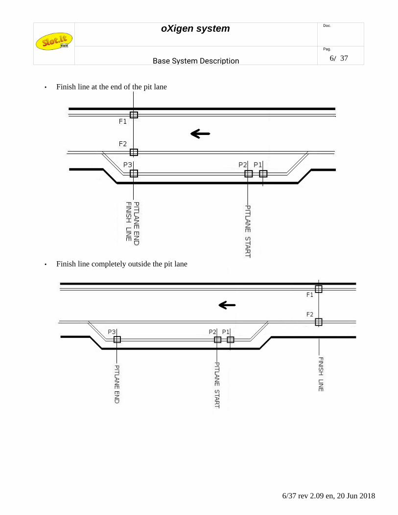
• Finish line at the end of the pit lane
• Finish line completely outside the pit lane
6/37 rev 2.09 en, 20 Jun 2018

oXigen system Doc.
Base System Description
Pag.
7/ 37
When in pit-lane, the car adjusts its maximum speed to 'pit lane speed' as set by the appropriate RMS knob.As of car firmware release 2.01, the car coasts to the selected pit lane speed . This means that the speedreduction is not immediate as the car does not apply any direct braking, hence the effect may not benoticeable for short pit lanes. Later firmware versions instead brake shortly as soon as the pit lane is detected,so that the car sets its speed to 'pit lane' speed immediately.
As you know by now, magnets are used to detect the finish line and the pit lane area. What happens if a carstopped right above a magnet? As this may cause uncertainties in the lap and pit lane detection, starting fromfirmware 2.07, should the car chip detect that the model has come to a halt right above a magnet, it wouldautomatically move forward to clear the 'magnet area' (note: only if the corresponding controller is on). Tryputting a car a few cm before the FL magnet, then slowly move the car forward with your fingertip: at acertain point it will, by itself, jump a few cm forward: this happens when a FL is detected for a time longerthan a defined threshold. You can use this feature to discover where the FL magnet is. Knowing where themagnets is may be important when reprogramming a car ID under certain conditions. Please refer to the 'IDProgramming' section.
7/37 rev 2.09 en, 20 Jun 2018
oXigen system Doc.
Base System Description
Pag.
8/ 37
Car chip
DC or AC+DC?The car is moved forward by the power it gets from the track. Such current and voltage can either be'continuous', such as the one coming from a standard battery, or 'alternate', like the power mains.
oXigen systems are preferably powered by DC power, and so are, in practice, Carrera and Ninco systems.
Scalextric SSD is unique in using AC power.
All oXigen chips are compatible with both:
1 - if the power on the rails is DC (analog track), or comes from Carrera or Ninco digital power bases, chipscan be either in DC or AC+DC modes. In this latter case, the car will be able to run in both directions, but itwill be slightly slower than if it was powered from the DC pad (0.5V loss approximately)
2 – if the rails are powered from an Hornby power base or a derivative, the AC setup must be used.
Unless you plan to use the chips on Scalextric SSD, leave them in DC mode, such as they are sold. Keep inmind that, anyway, the AC power mode is compatible with DC mode, but at the expense of some smallpower loss. To recap: for maximum power, and if system is DC, use DC mode (box stock). For universalcompatibility, use AC pads:
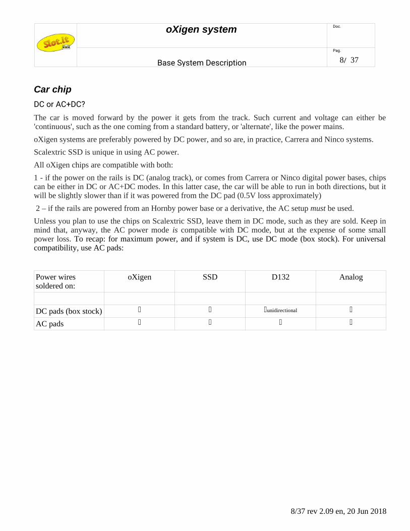
Power wires soldered on:
oXigen SSD D132 Analog
DC pads (box stock) unidirectional
AC pads
8/37 rev 2.09 en, 20 Jun 2018
oXigen system Doc.
Base System Description
Pag.
9/ 37
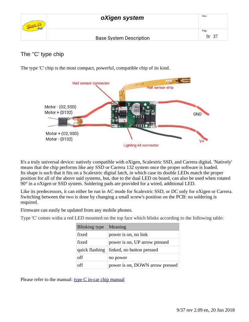
The ''C' type chip
The type 'C' chip is the most compact, powerful, compatible chip of its kind.
It's a truly universal device: natively compatible with oXigen, Scalextric SSD, and Carrera digital. 'Natively' means that the chip performs like any SSD or Carrera 132 system once the proper software is loaded. Its shape is such that it fits on a Scalextric digital latch, in which case its double LEDs match the proper position for all of the above said systems, but, due to the dual LED on board, can also be used when rotated 90° in a oXigen or SSD system. Soldering pads are provided for a wired, additional LED.
Like its predecessors, it can either be run in AC mode for Scalextric SSD, or DC only for oXigen or Carrera. Switching between the two is done by changing a small screw's position on the PCB: no soldering is required.
Firmware can easily be updated from any mobile phones.
Type 'C' comes witha a red LED mounted on the top face which blinks according to the following table:
Blinking type Meaning
fixed power is on, no link
fixed power is on, UP arrow pressed
quick flashing linked, no button pressed
off no power
off power is on, DOWN arrow pressed
Please refer to the manual: type C in-car chip manual
9/37 rev 2.09 en, 20 Jun 2018
oXigen system Doc.
Base System Description
Pag.
10/ 37
The 'B2' type chip (preliminary information)
The B2 type chip is a hybrid between B1, whose shape is retained, and C. It's designed for oXigen only, and uses the same connectors and pads that can be found on type B1 chip. Firmware updates are performed with the same procedure used for type C.
10/37 rev 2.09 en, 20 Jun 2018
oXigen system Doc.
Base System Description
Pag.
11/ 37
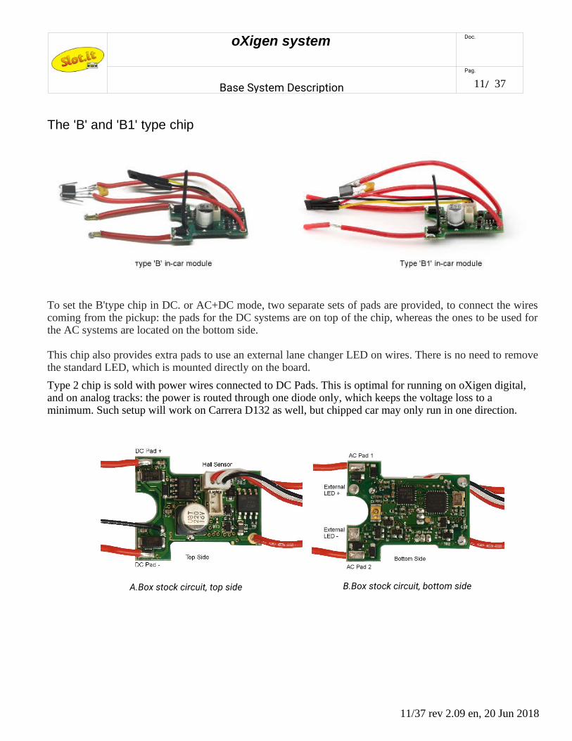
The 'B' and 'B1' type chip
To set the B'type chip in DC. or AC+DC mode, two separate sets of pads are provided, to connect the wirescoming from the pickup: the pads for the DC systems are on top of the chip, whereas the ones to be used forthe AC systems are located on the bottom side.
This chip also provides extra pads to use an external lane changer LED on wires. There is no need to removethe standard LED, which is mounted directly on the board.
Type 2 chip is sold with power wires connected to DC Pads. This is optimal for running on oXigen digital, and on analog tracks: the power is routed through one diode only, which keeps the voltage loss to a minimum. Such setup will work on Carrera D132 as well, but chipped car may only run in one direction.
11/37 rev 2.09 en, 20 Jun 2018
A.Box stock circuit, top side B.Box stock circuit, bottom side
oXigen system Doc.
Base System Description
Pag.
12/ 37
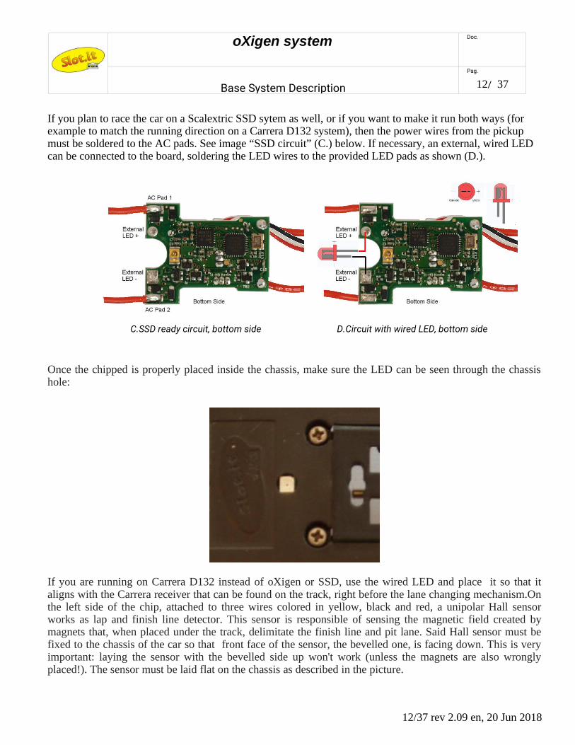
If you plan to race the car on a Scalextric SSD sytem as well, or if you want to make it run both ways (for example to match the running direction on a Carrera D132 system), then the power wires from the pickup must be soldered to the AC pads. See image “SSD circuit” (C.) below. If necessary, an external, wired LED can be connected to the board, soldering the LED wires to the provided LED pads as shown (D.).
Once the chipped is properly placed inside the chassis, make sure the LED can be seen through the chassishole:
If you are running on Carrera D132 instead of oXigen or SSD, use the wired LED and place it so that italigns with the Carrera receiver that can be found on the track, right before the lane changing mechanism.Onthe left side of the chip, attached to three wires colored in yellow, black and red, a unipolar Hall sensorworks as lap and finish line detector. This sensor is responsible of sensing the magnetic field created bymagnets that, when placed under the track, delimitate the finish line and pit lane. Said Hall sensor must befixed to the chassis of the car so that front face of the sensor, the bevelled one, is facing down. This is veryimportant: laying the sensor with the bevelled side up won't work (unless the magnets are also wronglyplaced!). The sensor must be laid flat on the chassis as described in the picture.
12/37 rev 2.09 en, 20 Jun 2018
C.SSD ready circuit, bottom side D.Circuit with wired LED, bottom side

oXigen system Doc.
Base System Description
Pag.
13/ 37
The antenna, which is the 2.5cm long piece of wire coming out from the top of the chip, should be kept
vertical, within the realms of possible. It is not recommended to lay the antenna flat down on the chip orclose to the motor. It will work, but it's not good practice.
Type 'B1' also comes witha a red LED mounted on the top face. It blinks according to the following table:
Blinking type Meaning
fixed power is on, no link
fixed power is on, UP arrow pressed
quick flashing linked, no button pressed
off no power
off power is on, DOWN arrow pressed
13/37 rev 2.09 en, 20 Jun 2018
oXigen system Doc.
Base System Description
Pag.
14/ 37
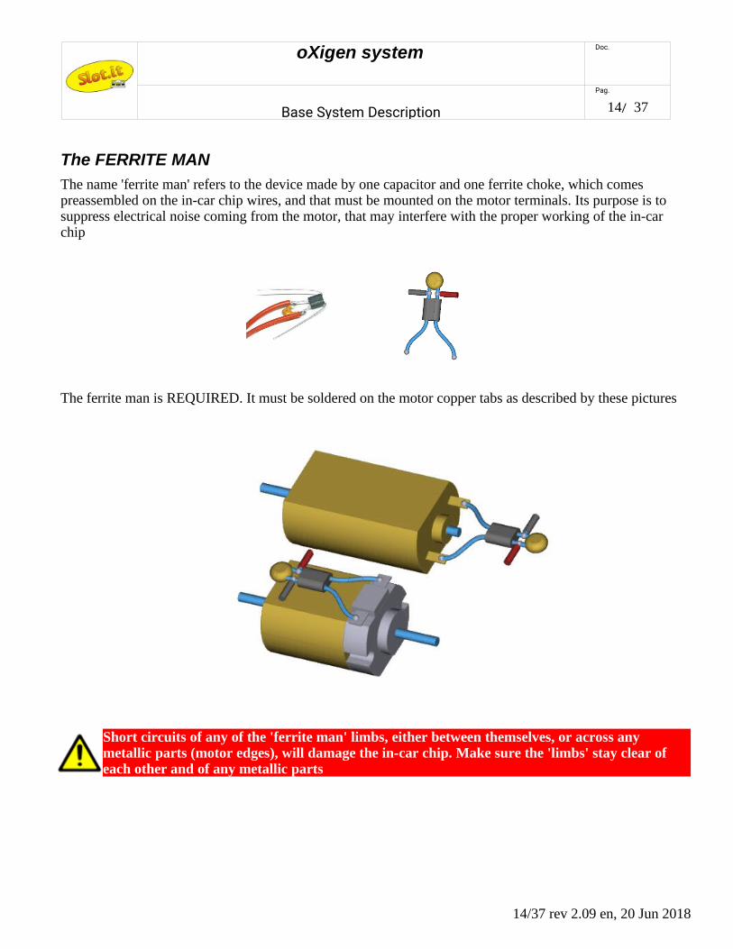
The FERRITE MAN
The name 'ferrite man' refers to the device made by one capacitor and one ferrite choke, which comes preassembled on the in-car chip wires, and that must be mounted on the motor terminals. Its purpose is to suppress electrical noise coming from the motor, that may interfere with the proper working of the in-car chip
The ferrite man is REQUIRED. It must be soldered on the motor copper tabs as described by these pictures
Short circuits of any of the 'ferrite man' limbs, either between themselves, or across any metallic parts (motor edges), will damage the in-car chip. Make sure the 'limbs' stay clear of each other and of any metallic parts
14/37 rev 2.09 en, 20 Jun 2018

oXigen system Doc.
Base System Description
Pag.
15/ 37
Car chip – type A (obsolete)
The O2 'type A' chip is now obsolete, having been replaced by type B. Car chip A can only run on DC, or ontracks powered by Ninco. It doesn't have any extra pads for AC systems nor any extra pads for wired LED.Type A chip is designed to fit the car as shown in the picture.The sensor has to be angled upwards at an angleof 45° at least (angle α in picture). This is very important: laying the sensor with the bevelled side up won'twork, and placing it flat on the chassis will cause detection of false laps. So: face down, angle up! Apart fromthe differences above, everything said for the type B chip applies.
Should you experience flase lap detection when changing lane, the reason is the high sensitivity of the Hallsensor in type A chips, which can detect the magnetic field of the activation coil during lane changing. Bendthe sensor more, or add some spacers underneath until the problem goes away.
If you are using a 'Type 2' chip, forget the above and leave the sensor flat on the chassis (rouned edge facingdownwards)
Besides, the Hall sensor is a current sensor, so keep it away from the power wires leading from track to chip,and from chip to motor.
15/37 rev 2.09 en, 20 Jun 2018
oXigen system Doc.
Base System Description
Pag.
16/ 37
oXigen in-car chip 'modes'
oXigen chipped cars can run on most commercially available digital systems: Scalextric SSD, Carrera D132, as well as of course oXigen native. In most cases, the communication between the car and the lane changers and/or lap counter is done through an infrared-emitting LED. Unfortunately, while oXigen and SSD share thebasics of such infrared protocol, SSD and Carrera systems are completely different. For this reason, each car must be programmed so that its working 'mode' is appropriate for the intended use.
Currently there are 5 such modes, one being still unused.
oXigen in-car chip working modes
Mode name System Note Display
'y' oXigen IR TX always on New oXigen default (from 07/14)
'o' oXigen IR TX on only when lane change activeOld oXigen default
'h' SSD Hornby SSD clone
- reserved -
'd' Carrera D132 Carrera Digital compatible
Modes can be selected either at controller-car pairing time with the appropriate procedure described herein (“controller and car link”), or with the Bootloader software.
oXigen 'hybrid' mode is necessary when runningoXigen chipped cars with SSD lane changers. It is anyway advisable to use it every time oXigen cars are used with lane changers based on Ninco track pieces. On Carrera based lane changers, it doesn't matter which oXigen mode is selected.
Please refer to the relevant sections to understand how to run oXigen chipped cars on SSD or Carrera systems.
16/37 rev 2.09 en, 20 Jun 2018
oXigen system Doc.
Base System Description
Pag.
17/ 37
Controller and car link – setup and programming
SCP-3
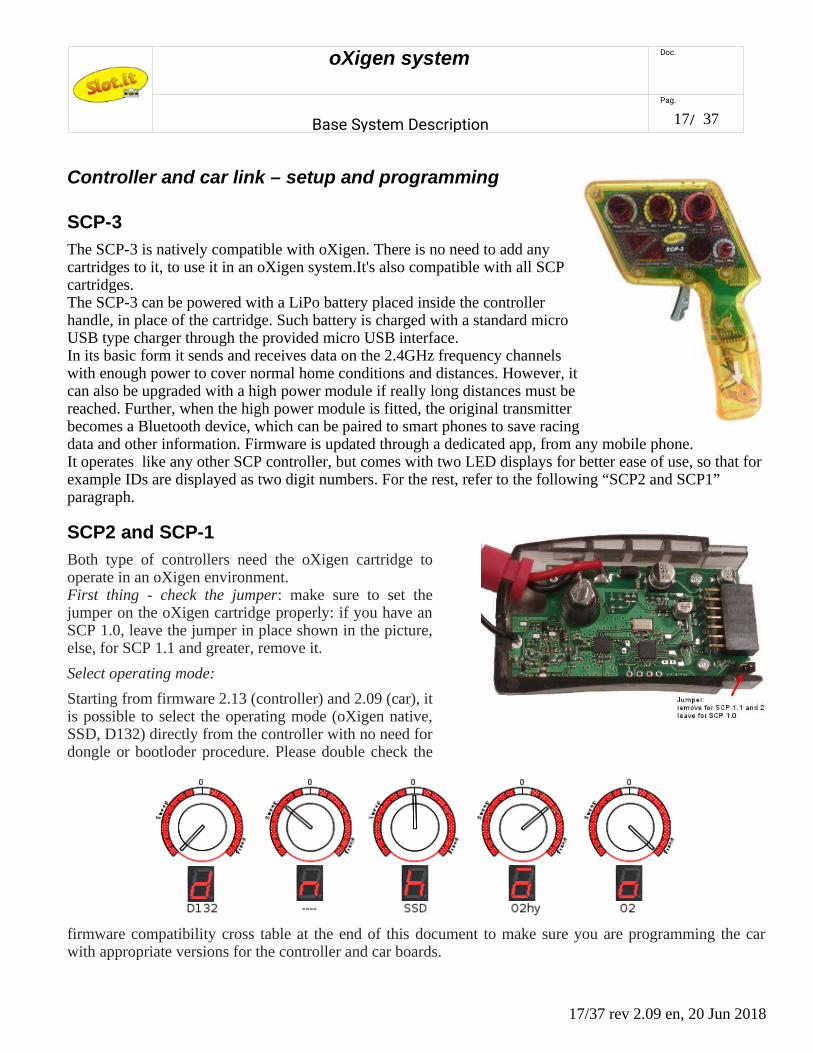
The SCP-3 is natively compatible with oXigen. There is no need to add anycartridges to it, to use it in an oXigen system.It's also compatible with all SCPcartridges.The SCP-3 can be powered with a LiPo battery placed inside the controllerhandle, in place of the cartridge. Such battery is charged with a standard microUSB type charger through the provided micro USB interface.In its basic form it sends and receives data on the 2.4GHz frequency channelswith enough power to cover normal home conditions and distances. However, itcan also be upgraded with a high power module if really long distances must bereached. Further, when the high power module is fitted, the original transmitterbecomes a Bluetooth device, which can be paired to smart phones to save racingdata and other information. Firmware is updated through a dedicated app, from any mobile phone.It operates like any other SCP controller, but comes with two LED displays for better ease of use, so that for example IDs are displayed as two digit numbers. For the rest, refer to the following “SCP2 and SCP1” paragraph.
SCP2 and SCP-1
Both type of controllers need the oXigen cartridge tooperate in an oXigen environment.First thing - check the jumper: make sure to set thejumper on the oXigen cartridge properly: if you have anSCP 1.0, leave the jumper in place shown in the picture,else, for SCP 1.1 and greater, remove it.
Select operating mode:
Starting from firmware 2.13 (controller) and 2.09 (car), itis possible to select the operating mode (oXigen native,SSD, D132) directly from the controller with no need fordongle or bootloder procedure. Please double check the
firmware compatibility cross table at the end of this document to make sure you are programming the carwith appropriate versions for the controller and car boards.
17/37 rev 2.09 en, 20 Jun 2018

oXigen system Doc.
Base System Description
Pag.
18/ 37
Check if the car is paired already - if not, assign an ID and pair it:
You may check now if the chipped car is already linked to the controller: power the track (make sure poweris on the rail), verify that controller is on, and put the chipped car on the track: if the cartridge red LEDblinks very fast, it means the car is already linked to the controller and you can start playing.
1. To check the current ID of the controller, press the round button: the display on the cartridge shows the current track, and the current channel of the car (cycling in this order :'t' ('track'), number of track, c ('channel'), number of channel, system type ('d' for Carrera D132, 'h' for Hornby SSD, 'o' for oXigen, and yes it's 'doh'). The dot on the low right side of the number, if lit, is the decimal light - that is: ' 9 ' means nine; ' 9. ' (nine with dot) means nineteeen. Number twenty is displayed as '||.'
2. To program a new channel, do as follows:
1. remove car from track
2. channel is programmed through the controller knobs. Proceed as follows:
1. The yellow (MIN) knob selects the track number: 0 -10= track 1, 10-20 track 2 and so on. Leave it at zero. For the time being, it has no effect, anyway.
2. The green (Antispin) knob selects the tens: set it between 0-10 for cars 1-9, 10-20 for cars 11 to 19, 20 and above for car 20
3. The blue (Curve) knob sets the units: 0 to 9 (minimum is 1)
4. The red (Brake) selects the system: turn fully counterclocwise (left) for Carrera D132, set to '0' (middle position) for Hornby SSD, set to 'two o' clock' for oXigen hybrid, turn fully clockwise (right) for pure oXigen. Note that this is necessary only if you want to change system to a different type. If you just need to change ID, this knob is not used.
3. now check the values that you are about to program by pressing the 'down arrow' together with the circular button: the display will show the settings for the track n. (currently, this can only be '1'), and the car ID. You can adjust them on the fly and as long as you keep pressing the down arrow and the round button, any changes are shown in real time. For example
't1 c8' means track 1, car ID n.8 and looks like this (leds turn on in sequence):
18/37 rev 2.09 en, 20 Jun 2018
4
3
0
2
1
0 10 0 10
Power Trim Min Speed Curve/Max
5 67
8
9
10
10
20

oXigen system Doc.
Base System Description
Pag.
19/ 37
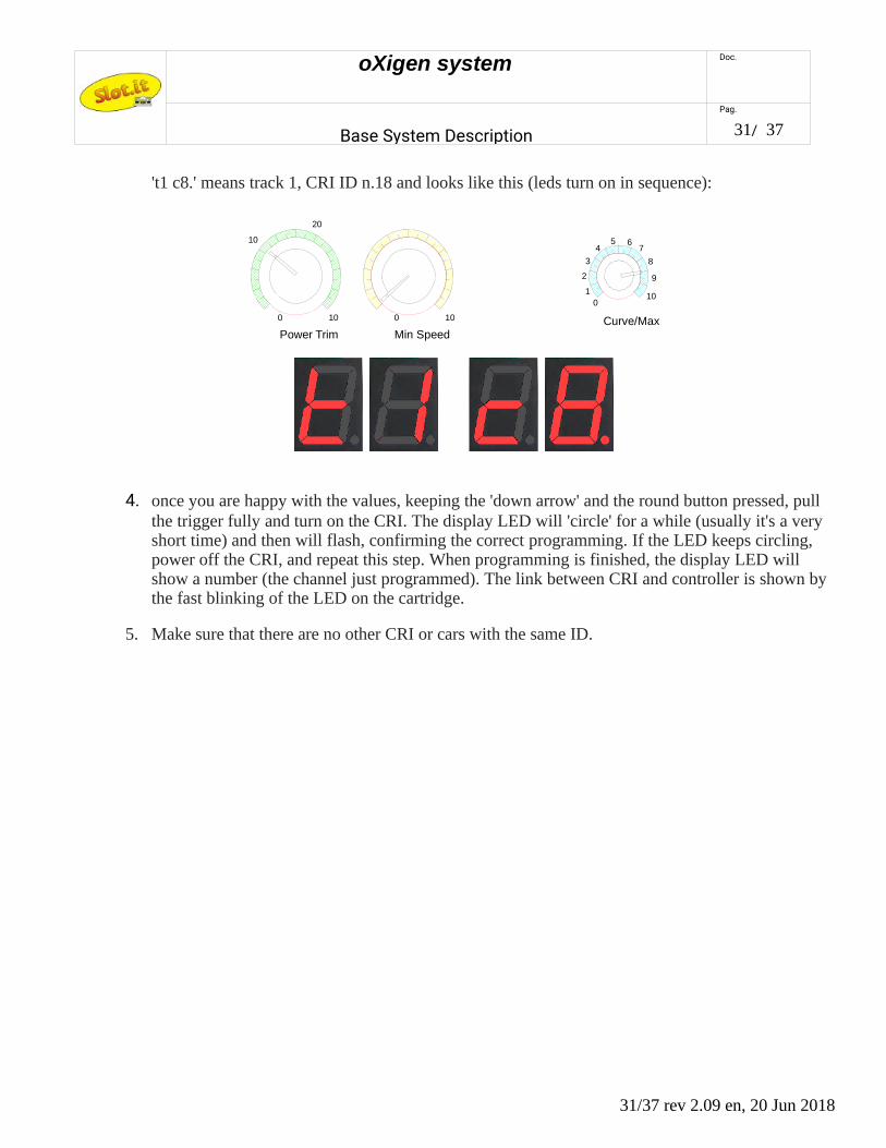
't1 c8.' means track 1, car ID n.18 and looks like this (leds turn on in sequence):
Note: SCP3 displays the ID as full two digit numbers :
4. if you want to check the system type as well (O2, D132, SSD), press both arrow and the circular buttons together: the display will show the settings for the track n. (currently, this can only be '1'), the car ID and the system type. For example, 't1 c6h' means track 1, car ID n.h, SSD mode and looks like this (leds turn on in sequence): in the following example note that the blue knob now points to '6'
19/37 rev 2.09 en, 20 Jun 2018
4
3
0
2
1
0 10 0 10
Power Trim Min Speed Curve/Max
5 67
8
9
10
10
20
4
3
0
2
1
0 10 0 10
Power Trim Min Speed Brake Curve/Max
5 67
8
9
10
10
20 0
oXigen system Doc.
Base System Description
Pag.
20/ 37
Important note: in this case, if you've reprogrammed the system as well as the ID (i.e. you've pressed both arrow and the circular buttons, and pulled the trigger), and your controller was in 'linear' mode (rear switch of the SCP on 'LIN'), then at this point your controller is in 'ghost' modeand your car may take off by otself. Exit the 'ghost' mode by pressing the trigger once, fully, before putting your car back on track.
5. once you are happy with the values, keeping the 'down arrow' and the round button pressed, pull the trigger fully and place the car to link with, on the (powered) track. The display LED will 'circle' for a while (usually it's a very short time) and then will flash, confirming the correct programming. If the LED keeps circling, remove the car from the track, and repeat this step. When programming is finished, the display LED will show a number (the channel just programmed). Reset car (remove from track and put back on track). The link between car and controller is shown by the fast blinking of the LED on the cartridge.
6. all of the above applies if you want to change to a different system, too, with the exception that you must press all the buttons (arrow up, arrow down and circular) and then pull the trigger.
Relinking controller and car
If you need to link the car to a controller other than the one that the car is currently linked to, you must in general make sure that the current 'owning' controller is switched off. This is a safety measure to prevent accidental reprogramming of someone else's car. However, starting from car firmware version 2.07 it is possible to reprogram the ID of a car to a different ID even if the car chip to be programmed is linked to a controller which is currently live. Now, if you need to perform such operation, that can be very handy sometimes (e.g. using one of your friends' cars while your friend is racing without asking him to switch his controller off), do as follows: if you know where a magnet is, put the controller, the one that you want to pairwith the car, in programming mode (select ID and press the trigger), then put the car on track right above the magnet, so that the chips wakes up with a magnet under the Hall sensor: under these conditions it will ignore any transmission from the previous controller and behave like a 'virgin' chip, accepting to be paired to any controller requesting to do so. Before you ask - with the new software the car will not stop inadvertently on amagnet - it will move forward automaticall to clear the area. This is also an easy way to find out where the magnets are.
Note that if the controller is switched off, and the car is taken off track, inside the pit lane, the pit lane status is lost, hence the 'end of pit lane' magnet will be detected not as a pit lane magnet, but as a finish line magnet,hence, one lap will be added to the lap counting. To avoid this, if both car and controller are switched off during pit lane, reposition the car after the pit lane exit magnet.
It is better to keep controllers at a distance of at least 30cm from each other.
20/37 rev 2.09 en, 20 Jun 2018

oXigen system Doc.
Base System Description
Pag.
21/ 37
Other functions
Lights: switching the lights on/off: the car chip is compatible with the lights kit SP16. To turn lights on/off, release the trigger and press the circular 'brake' button.
Battery level: if a 'b' appears in the cartridge display, it's time to change battery.
Reset: the red dot in the cartridge display turns on and stays on for 1 sec. when the car chip resets, e.g. when the car is placed on rails after a deslot (controller/car firmware 2.10/2.07 onwards)
Dropped link: the bottom red line in the cartridge display turns on and stays on for 1 sec. when the car chip does not receive properly a communication frame. What this means in practical terms: if at a certain point thecar does not receive timely throttle information from the controller, it has to slow down to avoid running away with no control and crashing. When this happens, it tries to cope with this situation as follows: if the loss happens during braking, then the car keeps braking as before. If, on the other hand, the link fails with open throttle, a gentle braking is applied for the first lost frame, only to switch to full brake if communicationdoes not restart (controller/car firmware 2.10/2.07 onwards)
If you experience stuttering, look at the display: a red dot means you have an electrical problem (reset due to power loss), a red line shows a bad radio link, which may be caused by interference from the motor: make sure the ferrite and capacitor are properly soldered and try to route power wires away from the antenna.
Make sure you are using controller and car software that are mutually compatible.
21/37 rev 2.09 en, 20 Jun 2018
oXigen system Doc.
Base System Description
Pag.
22/ 37
Ghost cars: any car can be used as a ghost car by using the 'ghost' function of the SCP1. Alternatively, the RMS can take control of any car linked to a controller, imposing a minimum speed on a specific car. More than one car can be linked to one controller, hence you can use as many cars as you wish, but they'll all behave as one (e.g. same speed).
The major difference from the SCP-controlled ghost cars, and the cars that are driven from the RMS software, is that with the SCP 'ghost' feature, cars change lane randomly, whereas if it's the RMS driving, thisis not the case.
Herding:
If the 'selective lane change' is available on your track, all cars can be forced to pit lane by the RMS.
Lane change
Refer to the Lane Change Driver manual file for detailed instructions.
Dongle
Refer to the Race Management System 'Crono' file for detailed instructions.
22/37 rev 2.09 en, 20 Jun 2018

oXigen system Doc.
Base System Description
Pag.
23/ 37
Using Arc Air/Pro Controller as oXigen controller
Any Scalextric Arc Air/Pro controller (ref. C8438) can be turned into an oXigen controller uploading the appropriate firmware into the unit. The operation can be done with a mobile phone equipped with either iOS or Android, and Nordic Semiconductor's 'nRF Toolbox' app.:
Firmware UpdatePrepare for the update:
1) Download the "nRF Toolbox for BLE" app by Nordic Semiconductor ASA from the Google Play store, and install it.
2) Download the O2ArcHCYYMMDD.zip file (YYMMDD=date of issue) and save it to a known location on your mobile device. Such file is included in the standard 'latest release' zip file available from the Slot.it site, oXigen downloads section. It will be probably placed in your 'Download' folder on your phone or SD card.
Set Controller to DFU mode:
1) With the controller OFF, press and HOLD the Brake (X) button and switch the ARC controller on. The controller should vibrate.
2) When the vibration stops, RELEASE the Brake button
23/37 rev 2.09 en, 20 Jun 2018
oXigen system Doc.
Base System Description
Pag.
24/ 37
3) Pull and HOLD the trigger (the controller will begin vibrating), then press and HOLD the brake (X) button again. The vibration will pause momentarily, then start again, and finally stop after approximately one second.
4) When the vribration stops completely, RELEASE the trigger and button. The controller should now be in Device Firmware Upload (DFU) mode, and remain in that mode until programmed or reset by turning it off and back on.
Upload the firmware
1) Start the nRF toolbox app and select DFU
2) Tap on SELECT DEVICE and choose "DfuArcHC" which should appear in the list of available devices, below your list of paired/bonded devices. If it is not present, repeat the steps above to set the controller to DFU mode.
3) Tap on SELECT FILE, then ensure that "Distribution packet (zip)" is selected, then tap OK.
4) Using the file browser, locate and select the O2onArcHCYYMMDD.zip file. The app will return to theDFU screen when the file has been selected.
5) Tap on UPLOAD
The controller resets automatically after being upgraded, but may need to be turned off and then back on to control the slot car.
Controller's eeprom is not changed, so no pairing should be needed if the controller was already paired.
Pairing to Car
1) Make sure any previously paired controller is turned off.
2) Put the car on the powered track. If it's an automatic car, make sure it's Hall sensor is positioned over a magnet.
3) Press and HOLD (in this order) the Lane Change (Y) and Brake (X) buttons.
4) When the LED turns ON for two seconds and then turns off, RELEASE the buttons.
5) Press the Brake button as many times as the ID you want to give the car. The LED lights each time the button is pressed.
6) Press and HOLD (in this order) the Lane Change (Y) and Brake (X) buttons and pull the trigger.
7) When the LED intensity increases then goes off and the controller vibrates, pairing was successfull and you can RELEASE the buttons and trigger.
8) Turn the controller off and back on to control the car.
24/37 rev 2.09 en, 20 Jun 2018
oXigen system Doc.
Base System Description
Pag.
25/ 37
Running with Hornby SSD Digital
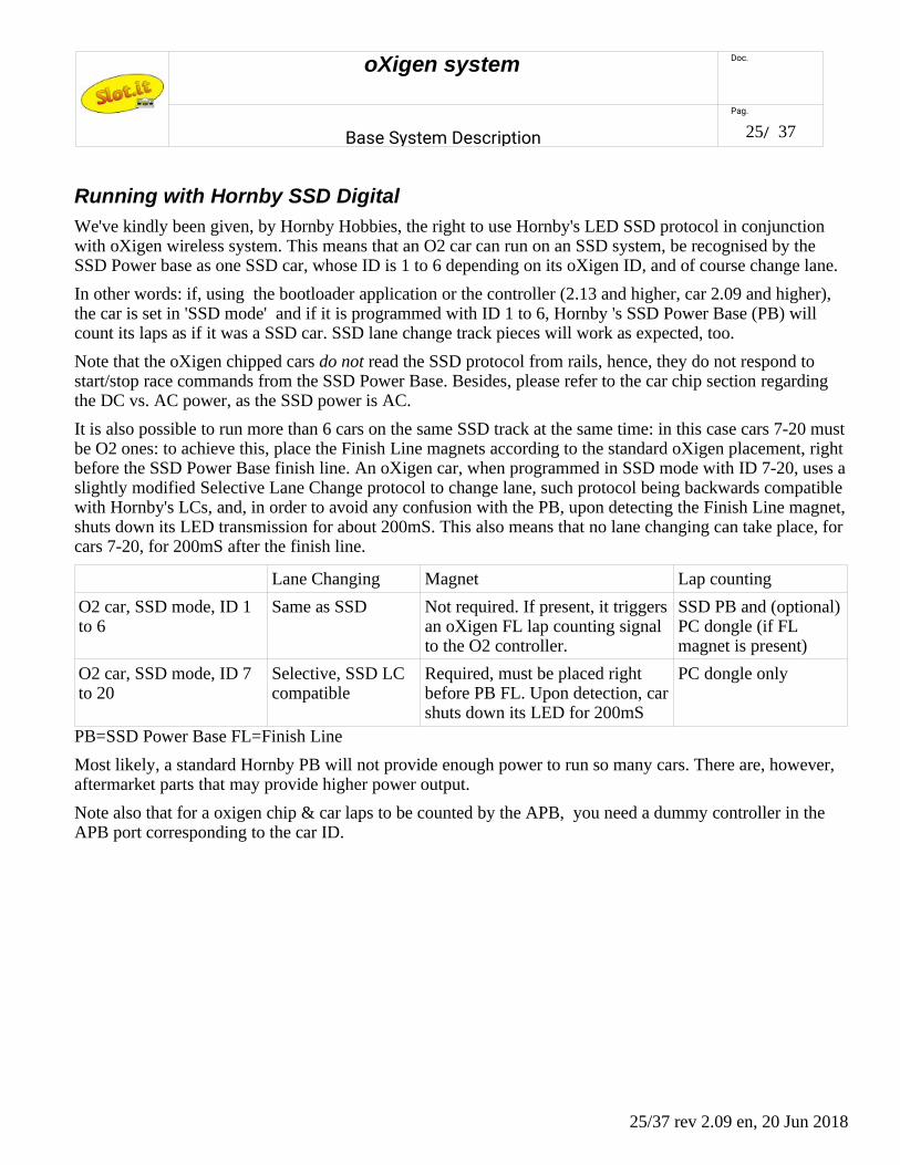
We've kindly been given, by Hornby Hobbies, the right to use Hornby's LED SSD protocol in conjunction with oXigen wireless system. This means that an O2 car can run on an SSD system, be recognised by the SSD Power base as one SSD car, whose ID is 1 to 6 depending on its oXigen ID, and of course change lane.
In other words: if, using the bootloader application or the controller (2.13 and higher, car 2.09 and higher), the car is set in 'SSD mode' and if it is programmed with ID 1 to 6, Hornby 's SSD Power Base (PB) will count its laps as if it was a SSD car. SSD lane change track pieces will work as expected, too.
Note that the oXigen chipped cars do not read the SSD protocol from rails, hence, they do not respond to start/stop race commands from the SSD Power Base. Besides, please refer to the car chip section regarding the DC vs. AC power, as the SSD power is AC.
It is also possible to run more than 6 cars on the same SSD track at the same time: in this case cars 7-20 mustbe O2 ones: to achieve this, place the Finish Line magnets according to the standard oXigen placement, right before the SSD Power Base finish line. An oXigen car, when programmed in SSD mode with ID 7-20, uses aslightly modified Selective Lane Change protocol to change lane, such protocol being backwards compatible with Hornby's LCs, and, in order to avoid any confusion with the PB, upon detecting the Finish Line magnet,shuts down its LED transmission for about 200mS. This also means that no lane changing can take place, for cars 7-20, for 200mS after the finish line.
Lane Changing Magnet Lap counting
O2 car, SSD mode, ID 1 to 6
Same as SSD Not required. If present, it triggersan oXigen FL lap counting signal to the O2 controller.
SSD PB and (optional)PC dongle (if FL magnet is present)
O2 car, SSD mode, ID 7 to 20
Selective, SSD LC compatible
Required, must be placed right before PB FL. Upon detection, carshuts down its LED for 200mS
PC dongle only
PB=SSD Power Base FL=Finish Line
Most likely, a standard Hornby PB will not provide enough power to run so many cars. There are, however, aftermarket parts that may provide higher power output.
Note also that for a oxigen chip & car laps to be counted by the APB, you need a dummy controller in the APB port corresponding to the car ID.
25/37 rev 2.09 en, 20 Jun 2018

oXigen system Doc.
Base System Description
Pag.
26/ 37
Running with Carrera Digital D132
It is possible to run an oXigen chipped car on Carrera Digital D132. This is done independently of Carreraprotocols and technology. Actually, it is the D132 PB that does the job for us. A fully working Carrera D132system (PB + LCs + controller) is required.
In D132 systems the PB transmits the status of the 'change lane' buttons on the hand controllers, to all thelane change units. Car chips, instead, know nothing about the lane change button: they go around the tracktransmitting their fixed ID continuosly through the IR LED. The LC thus knows from the PB if a certain carmust change lane, and once such car is recognised, the LC mechanism is activated.
An oXigen car in D132 mode sends its ID only when the LC button is pressed: in all other cases (except forlap counting), it goes around undetected. If, at the same time, the PB senses from its own controller that suchcar wants to change lane, and the oXigen LC button is pressed, any LC can pick up the infrared ID from thecar, which can thus change lane at will.
To count laps, though, you must place a oXigen FL magnet right before the Carrera D132 FL sensor to trigger a 200mS transmission of the car's ID, which will be picked up by the FL sensor. Thus, a LC must not be placed right after the FL, or the O2 cars will change lane.
To summarise, how to do? First, with the Bootloader software (0.12 and higher), or controller (2.13 and higher, car 2.09 and higher) put your O2 car in D132 mode. Then, program it with ID ranging between 1 and 6. Last, plug your Carrera controller in the PB slot corresponding to said ID, lock the LC button on the 'ON' position (for example, with a rubber band), make sure magnets are placed under the FL, and you're ready.
Note that the oXigen chipped cars do not read the Carrera digital protocol from rails, hence, they do not respond to start/stop race commands from the Power Base.
It is also possible to run more than 6 cars on the same Carrera track at the same time. Again, you need the magnets under the FL. In this case cars 7-20 must be O2 ones and Carrera ID 4 is reserved for O2 extension.You need a Carrera controller hooked to controller plug n.4 with its LC button locked on. Then, simply, put your cars in D132 mode, set them to ID 7 to 20, and run them. In this case an oXigen dongle is requiredfor lap counting.
Lane Changing Magnet Lap counting
O2 car, D132 mode,ID 1 to 6
Needs Carrera controller (or shorted jack) with LC button pressed in the same PB slot as the car's ID
Required, must be placed right before D132 FL. It triggers an oXigen FL signal to the O2 controller as well as a D132 lap.
D132 PB and (optional) PC dongle
O2 car, D132 mode,ID 7 to 20
Needs Carrera controller (or shorted jack) with LC button pressed in PB slot n.4
Required, must be placed right before D132 FL. It triggers an oXigen FL signal to the O2 controller.
PC dongle only
PB=D132 Power Base FL=Finish Line
Note that the IR LED must be displced to match the position of the receiving LED on Carrera track, so a LED on wires is advisable, together with a O201b chip.
Most likely, a standard Carrera PB will not provide enough power to run more than 6 cars. There may be, however, aftermarket parts providing higher power output.
26/37 rev 2.09 en, 20 Jun 2018

oXigen system Doc.
Base System Description
Pag.
27/ 37
27/37 rev 2.09 en, 20 Jun 2018

oXigen system Doc.
Base System Description
Pag.
28/ 37
Cartridge Radio Interface (CRI)
The O2 Cartridge Radio Interface (CRI), when used together with an oXigen SCP cartridge, creates a radio wireless communication link between the hand controller (SCP only) and any available SCP cartridge - analog or digital, turning in fact a SCP controller into a wireless system for any slot car racing system in the world – analog (common ground or common positive) or digital (Hornby, Carrera, Ninco, SCX).
In detail, the CRI is a pocket size receiver accepting any SCP cartridge: think of it as the top of the SCP controller, but with no knobs or trigger. It connects by 2.4GHz radio link to the oXigen cartridge which is plugged into the SCP controller, and transmits in real time the power, brake and any other commands (lane change, lights, etc.) coming from the controller to the cartridge, thus creating a wireless, remote control SCP system for all the SCP-1 supported systems: .
How does it all work? As far as the SCP + O2 cartridge know, the CRI is just an O2 car chip. At the CRI endinstead, the data received from the SCP are passed on to the final cartridge. It's very simple.
In practice the CRI has to be paired to the SCP following the same procedure described above for “controllerand car link – setup and programming”. Note that the position of the brake knob of the SCP (which is usedto select between oXigen, Hornby SSD or Carrera digital) is irrelevant.
28/37 rev 2.09 en, 20 Jun 2018

oXigen system Doc.
Base System Description
Pag.
29/ 37
Controller and CRI link – setup and programming
You need one SCP controller handle, one oXigen cartridge, the correct analog or digital cartridge for yoursystem and one CRI. Plug the oXigen cartridge into the SCP. Plug the analog or digital cartridge into the CRI, as if the CRI was a controller. Teh system will look like the one in the picture: a complete SCP with oXigen cartridge, and one analog or digital cartridge assembled with the Common Radio Interface box.
Prepare and check your controller as if you were about to link to a car. Everything applies, except the position of the brake knob, which is irrelevant. Once ready, plug your cartridge/CRI combination into your track power supply, and link it to the controller following the usual procedure. If you already know how to link one car, you can skip the rest of this chapter. Else, read below.
First of all: make sure to set the jumper on the oXigen cartridge properly: if you have an SCP 1.0, leave thejumper in place shown in the picture, else, for SCP 1.1 and greater, remove it.
29/37 rev 2.09 en, 20 Jun 2018

oXigen system Doc.
Base System Description
Pag.
30/ 37
You can check now if the CRI is already linked to the controller: power on the track and controller: if boththe cartridge and the CRI red LEDs blink fast, the CRI is already linked to the controller and you can startracing.
1. To check the current ID of the controller, press the round button: the display on the cartridge shows the current track, and the current channel of the CRI (cycling in this order :'t' ('track'), number of track, c ('channel'), number of channel, system type ('d' for Carrera D132, 'h' for Hornby SSD, 'o' for oXigen, and yes it's 'doh', but this information can be ignored with the CRI). The dot on the low right side of the number, if lit, is the decimal light - that is: ' 9 ' means nine; ' 9. ' (nine with dot) means nineteeen. Number twenty is displayed as '||.'
2. To program a new channel, do as follows:
1. switch off the CRI
2. channel is programmed through the controller knobs. Proceed as follows:
1. The yellow (MIN) knob selects the track number: 0 -10= track 1, 10-20 track 2 and so on. Leave it at zero.
2. The green (Antispin) knob selects the tens: set it between 0-10 for CRI 1-9, 10-20 for CRI 11 to 19, 20 and above for CRI 20
3. The blue (Curve) knob sets the units: 0 to 9 (minimum is 1)
4. The red (Brake) position is irrelevant with the CRI.
3. now check the values that you are about to program by pressing the 'down arrow' together with the circular button: the display will show the settings for the track n. (currently, this can only be '1'), and the CRI ID. You can adjust them on the fly and as long as you keep pressing the down arrow and the round button, any changes are shown in real time. For example
't1 c8' means track 1, CRI ID n.8 and looks like this (leds turn on in sequence):
30/37 rev 2.09 en, 20 Jun 2018
4
3
0
2
1
0 10 0 10
Power Trim Min Speed Curve/Max
5 67
8
9
10
10
20
oXigen system Doc.
Base System Description
Pag.
31/ 37
't1 c8.' means track 1, CRI ID n.18 and looks like this (leds turn on in sequence):
4. once you are happy with the values, keeping the 'down arrow' and the round button pressed, pull the trigger fully and turn on the CRI. The display LED will 'circle' for a while (usually it's a very short time) and then will flash, confirming the correct programming. If the LED keeps circling, power off the CRI, and repeat this step. When programming is finished, the display LED will show a number (the channel just programmed). The link between CRI and controller is shown by the fast blinking of the LED on the cartridge.
5. Make sure that there are no other CRI or cars with the same ID.
31/37 rev 2.09 en, 20 Jun 2018
4
3
0
2
1
0 10 0 10
Power Trim Min Speed Curve/Max
5 67
8
9
10
10
20

oXigen system Doc.
Base System Description
Pag.
32/ 37
Controller, oXigen cartridge and ARC AIR / PRO – setup and programming
The 2.4 GHz link between Scalextric ARC AIR/PRO Power Base and Controllers was developed by GalileoEngineering, also known as Slot.it, for, and in strict cooperation with, Hornby Hobbies plc. All that waslearnt from developing Slot.it's own digital wireless system during the course of many years has beentransferred into Scalextric ARC system, creating a fantastic wireless system with great reliability,smoothness of operation, and operating range, for the beginner and the experienced racer alike.
As it could be expected, any SCP controller with oXigen cartridge is the perfectcontroller racing upgrade to Scalextric ARC AIR/PRO systems. All you have to do isto load the appropriate firmware, which can be grabbed from Slot.it's oXigendownload pages, and program the cartridge using the usual oXigen bootloaderapplication. Once this is done, your SCP will be ready to operate as an ARCcontroller. All the SCP controls remain operational, with the exception of variablebraking, which will only become available later on.
Operating instructions
1. Grab ARC AIR/PRO compatible firmware from Slot.it web site, oXigen download section
2. Transfer firmware into SCP's memory using oXigen bootloader application
3. Pair the SCP controller to Scalextric ARC Power Base as if it was a ARC AIR/PRO controller: pressthe channel button on the Power Base, then press the ROUND and ARROW DOWN buttons togetherand pull the trigger.
4. When the controller is paired, the link LED on the cartridge blinks like it does oXigen mode.
5. press the BRAKE button to show the ARC track ID (1-4) and current channel ID (1-2 for AIR, 1-6for PRO)
The SCP3 (wireless only, battery powered SCP) automatically detects whether it's being used in an oXigenor ARC environment and adapts accordingly, without any reprogramming.
32/37 rev 2.09 en, 20 Jun 2018

oXigen system Doc.
Base System Description
Pag.
33/ 37
Software compatibility and development table
The oXigen system is constantly being upgraded, improved, maintained.This table describes what are the latest versions, and possible incompatibilities.
Last known good version - oXigen
Dongle Controller Car CRI
2.14 2.26 2.13(type A, B), 2.14 (B1) 2.03
Last known good version - Scalextric ARC
Power Base (Hornby) Controller
0.11 5.00
33/37 rev 2.09 en, 20 Jun 2018

oXigen system Doc.
Base System Description
Pag.
34/ 37
Galileo Engineering – Slot.it signed driver installation guideThis guide describes how to install the self-signed drivers released by Galileo Engineering srl – Slot.it
To start with, the latest Windows OS (Windows 7 onwards) requires digitally signed drivers. These filesinclude an electronic fingerprint indicating the details of the issuing company and a few more parameters.Signing a driver is an important security measure, because a malicious infection may not modify a signeddriver without compromising its signature. Thus, drivers are signed using code signing certificates. Unsigneddrivers can still be installed under Windows OS anyway, disabling signature verification, but it's not arecommended practice. The procedure is well explained on many websites but is not user friendly and,frankly, is not a very professional practice.
Galileo Engineering currently provides digitally signed drivers for two USB devices: oXigen Dongle andLive Timing Box (LTB). Compressed folders with all necessary files can be downloaded directly from thedownload section og the Slot.it web site (http://www.slot.it). The following examples refer to oXigen dongledriver installation but apply to the Live Timing device as well.
Installation is a two steps process:
1 – Signed certificate installation
2 – Driver Installation
1 – Signed certificate installation
This should be required once only, that is, the first time a Slot.it USB device is installed on the PC. Theprocedure intalls a Galileo Engineering digital certificate which is used by Windows to make sure that theSlot.it signed drivers can be trusted. A trusted driver will not be removed every time Windows gets updated,which is what happens to unsigned drivers instead.
Download the compressed driver files folder from the Slot.it website and uncompress the folder, whichincludes three files:
1 : a text file consisting of the driver information (.inf)
2 : a catalog file used as digital signature for the driver file (.cat)
3 : company signed certificate (.cer)
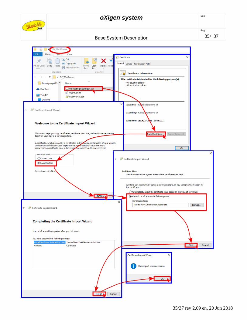
The first step is installing the Galileo Engineering certificate:
• doubleclick on certificate file (GalileoEngineeringsrl.cer in the example)• click on Install Certificate• select Local Machine → Next• select Place all certificates in the following store and browse Trusted Root Certification
Authorities → Next• click on Finish • confirm with OK
From now on, all drivers that are signed with the certificate will be trusted.
34/37 rev 2.09 en, 20 Jun 2018
oXigen system Doc.
Base System Description
Pag.
35/ 37
35/37 rev 2.09 en, 20 Jun 2018
oXigen system Doc.
Base System Description
Pag.
36/ 37
2 – Driver Installation
To complete the driver installation, proceed as follows:
• plug the device (oXigen dongle in the example) in the PC• open Control Panel → Hardware and Sound → Device Manager• look under Ports (COM & LPT): the device shows up as Serial USB Device (COM xx) unless an
unsigned driver was previously installed, in which case 'oXigen dongle' will be reported instead. Inthis latter case, right click, select 'uninstall', click, unplug the dongle and go back to the beginning.
• right click on Serial USB Device → Update Driver Software• select Browse my computer for driver software• select the driver location browsing to the driver folder → Next• flag Always trust software from “Galileo Engineering srl” → Install on the Windows Security
prompt • click Close to confirm the driver software installation• run again to Control Panel → Hardware and Sound → Device Manager• under Ports (COM & LPT) , the device appears as oXigen Dongle (COM xx) • click right on oXigen Dongle → Properties → Driver • drivers details: Drivers Provider : Slot.it , Digital Signer : Galileo Engineering srl • click OK to esc
36/37 rev 2.09 en, 20 Jun 2018

oXigen system Doc.
Base System Description
Pag.
37/ 37
37/37 rev 2.09 en, 20 Jun 2018