oxygen plasma treatment for reducing hydrophobicity of a ... · pdf fileprotocol to produce...
TRANSCRIPT

Griffith Research Online
https://research-repository.griffith.edu.au
Oxygen plasma treatment forreducing hydrophobicity of a sealedpolydimethylsiloxane microchannel
AuthorTan, Say Hwa, Nguyen, N., Chua, Yong Chin, Kang, Tae Goo
Published2010
Journal TitleBiomicrofluidics
DOI https://doi.org/10.1063/1.3466882
Copyright StatementCopyright 2010 American Institute of Physics. This article may be downloaded for personal use only.Any other use requires prior permission of the author and the American Institute of Physics. Thefollowing article appeared in Biomicrofluidics, Vol. 4, pp. 032204-1-032204-8, 2010 and may be found athttp://dx.doi.org/10.1063/1.3466882.
Downloaded fromhttp://hdl.handle.net/10072/62250

APS/123-QED
Oxygen plasma treatment for reducing hydrophobicity of a sealed
polydimethylsiloxane (PDMS) microchannel
Say Hwa Tan, Nam-Trung Nguyen,∗ and Yong Chin Chua
School of Mechanical and Aerospace Engineering,
Nanyang Technological University, 50 Nanyang Avenue, Singapore, 639798
Tae Goo Kang
Institute of Microelectronics, Science Park II, Singapore 117685
(Dated: May 6, 2010)
Abstract
Rapid prototyping of polydimethylsiloxane (PDMS) is often used to build microfluidic devices.
However, the inherent hydrophobic nature of the material limits the use of PDMS in many ap-
plications. While different methods have been developed to transform the hydrophobic PDMS
surface to a hydrophilic surface, the actual implementation proved to be time consuming due to
differences in equipments and the need for characterization. This paper reports a simple and easy
protocol combining a second extended oxygen plasma treatments and proper storage to produce
usable hydrophilic PDMS devices. The results show that at an plasma power of 70 W, an ex-
tended treatment of over 5 minutes would allow the PDMS surface to remain hydrophilic for more
than 6 hours. Storing the treated PDMS devices in DI water, would allow them to maintain their
hydrophilicity for weeks. Atomic force microscopy (AFM) analysis shows that a longer oxygen
plasma time produces a smoother surface.
PACS numbers:
∗Electronic address: [email protected]
1

I. INTRODUCTION
Polydimethylsiloxane (PDMS) is one of the most widely used silicone-based polymers
in microfluidics [1]. The ease of fabrication, low cost, bio-compatibility, elastomeric prop-
erty and optical transparency are attractive reasons for its wide usage in rapid prototyping
[2]. However despite these advantages, the intrinsic hydrophobicity of PDMS restricts its
use in certain applications. Analysis of biological samples and chemical synthesis require
hydrophilic surfaces [4] in order to work expeditiously. Electrophoretic separation [5] also
requires adequate surface wettability. Stable droplets [6] and bubbles [7] formation require
the continuous phase fluid to preferentially wet the channel walls. From the above mentioned
applications, surface properties of PDMS are to be considered in the design and fabrication
of microfluidic devices.
In the past, the surface properties of PDMS has been modified using different methods
such as coating of the inner walls [8], attachment of active groups [9], plasma oxidation
[10], thermal aging [11] and chemical coating [12]. However, most methods require hours
to process and to characterize before one can effectively use the devices. In addition, the
varieties in technologies and equipments of different laboratories cause further delay in the
implementation of the technology. Recognizing this predicament, this paper reports a simple
protocol to produce PDMS with hydrophilic channel walls without the use of additional
chemicals or equipment. The characterisation of this method also ensures that the device
can be stored for days before use while maintaining the hydrophilicity of the channel walls
within a time span reasonable for experimentation.
Oxygen plasma treatment has been used extensively by many in the fabrication of PDMS
microfluidic devices. The treatment of oxygen plasma on PDMS introduces polar functional
groups [13] which is mainly the silanol group (SiOH). This group changes the surface prop-
erties of PDMS from being hydrophobic to hydrophilic. On the one hand, normal plasma
treated surfaces undergo hydrophobic recovery within minutes [14] after bonding and ther-
mal treatment. On the other hand, extended plasma treatment induces undesirable surface
cracks [13] which affects the bonding integrity of the device. Hydrophobic recovery of PDMS
has been well studied by sessile water contact angle measurement [15], scanning electron
microscopy (SEM) [16] and X-ray photoelectron spectroscopy [17]. The main reasons for
hydrophobic recovery are the reorientation of the polar groups from the surface to the bulk
2

[17], diffusion of pre-existing low-molecular-weight (LMW) species from the bulk to the sur-
face [16] and condensation of the hydroxyl groups [18]. The recovery rate is also affected by
storage condition such as temperature [11], humidity [19], aqueous fluid [20] and surfactants
[21] used to store the PDMS device. To our knowledge, limited or very few studies report on
surface modification using a bonded and sealed PDMS device. Most studies are conducted
using thin PDMS membranes which are not bonded together to form a typical concealed
microfluidic device. The main purpose of the technique reported in this paper is to perform
surface modification of a fully bonded and functional microfluidic device.
II. MATERIALS AND METHODS
The test devices used in this work is fabricated using standard soft lithography [22]. To
summarise, we casted the PDMS substrate (Sylgard 184, Dow Corning) on a master mold
made of the thick-film resist SU-8. The thickness of the SU-8 layer is 100 µm. The PDMS
substrate with the microchannel was first peeled off from the master mold. A manual
puncher (Harris Uni-Core, World Precision Instruments, Inc., Florida, USA) of 0.75 mm
diameter was then used to create the fluidic access into the device. Oxygen plasma created
by a plasma reactor (790 Series, Plasma-Therm, Inc., Florida, USA) was then used to bond
the former PDMS substrate to a slab of blank PDMS. The bonded PDMS devices were then
placed in an oven at 150 ◦C for two hours to ensure good bonding between both surfaces.
Figure 1 shows the schematic sketch of the microchannel used in the test. The straight
channel has a width of 150 µm and a height of 100 µm. Contact angle measurement are
carried out for a stationary water plug in the channel as depicted in Fig. 1(a).
The fully bonded and leak free devices subsequently underwent a second oxygen plasma
treatment. A total of six different treatment times were used to study the effectiveness of
the protocol proposed. While the plasma power was kept constant at 70 W, the treatment
times were varied as 100, 200, 300, 400 and 500 seconds. Immediately after the plasma
treatment, the devices were immersed in a container filled with DI water. Air bubbles are
removed by injecting DI water through the access holes and storing in a vacuum chamber
for 7 days. This duration provides a realistic time scale in commercial context, where the
storage and delivery of the devices may take longer than in the laboratory environment.
The vacuum ensures that all air bubbles trapped in the devices were removed and devices
3

8 mm
Flat slab of PDMS (0.5 cm thick) Channel Access hole PDMS
(1 cm thick)
FIG. 1: Schematic sketch of the test device used in the experiment (not to scale, the channel
has a length of 8 mm): (a) Water plug in a hydrophobic channel (θ > 90◦), (b) Water plug in a
hydrophilic channel (θ < 90◦), (c) cross section
are stored at a constant low temperature.
For the characterization experiments, the devices were removed from the vacuum chamber
and DI water within the microchannels was removed manually using syringes. In order to
ensure a minimal amount of DI water remaining in the channel, manual pumping of the
syringes were repeated at least 20 times. Thereafter, DI water is pumped into the device
at a very slow rate of 1 µl/hr using a precision syringe pump (KDS 250, KD Scientific).
The flow is then stopped when the fluid just entered the inlet port. A stabilisation time
of 5 mins is then used to obtain a near static image of the clear meniscus of the water/air
interface. An epi-fluorescent inverted microscope (Nikon, Eclipse TE2000-S) was used to
observe the meniscus of the the liquid inside the channel. A sensitive interline transfer
CCD camera (HiSense MKII, Dantec Dynamics, Denmark) was employed for recording the
meniscus image. Images of the interfaces were then taken at period of 0, 2, and 4 and 6
hours from the time the devices are exposed to the ambient air. In addition, to ensure fair
experimental conditions, all the fluids are pumped out manually after each recording4.
4

Water Water Air
DetectedInterface
(a) (b)
FIG. 2: Evaluation of contact angle using the customised MATLAB program (the image is taken
using a bonded pristine PDMS device): (a) Original image, (b)Processed image
Figure 2 shows an example of the meniscus image taken at the interface for a bonded
pristine PDMS microfluidic device. A total of 20 pictures using 10 similar devices for each
plasma parameter are then evaluated and averaged using a customized MATLAB program.
The program first imports the bitmap image and convert it into a binary form. Subsequently,
the water/air interface was detected by the contrast of the interface. The radius of curvature
R was detected by curve fitting. With the known channel width W of 150 µm, the contact
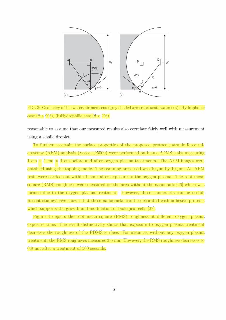
angle is determined in degree for hydrophobic case as (Fig. 3(a)):
θ =180◦
πarccos
(−W
2R
)(1)
For the hydrophilic case, the contact angle is (Fig. 3(b)):
θ =180◦
πarccos
(W
2R
)(2)
The measured results for the case of a bonded pristine PDMS microfluidic device (without
the second plasma treatment) agrees well with the reported result measured using conven-
tional contact angle measurement with a sessile water droplet. For our case, the contact
angle measured was about 120◦ while the reported case was about 112◦ [3]. Therefore, it is
5
W/2
q
p-q
p-q
R W/2
q
p-qq
R
W W
(a) (b)
O
A
B OB
A
FIG. 3: Geometry of the water/air meniscus (grey shaded area represents water) (a): Hydrophobic
case (θ > 90◦), (b)Hydrophilic case (θ < 90◦).
reasonable to assume that our measured results also correlate fairly well with measurement
using a sessile droplet.
To further ascertain the surface properties of the proposed protocol, atomic force mi-
croscopy (AFM) analysis (Veeco, D5000) were performed on blank PDMS slabs measuring
1 cm × 1 cm × 1 cm before and after oxygen plasma treatments. The AFM images were
obtained using the tapping mode. The scanning area used was 10 µm by 10 µm. All AFM
tests were carried out within 1 hour after exposure to the oxygen plasma. The root mean
square (RMS) roughness were measured on the area without the nanocracks[26] which was
formed due to the oxygen plasma treatment. However, these nanocracks can be useful.
Recent studies have shown that these nanocracks can be decorated with adhesive proteins
which supports the growth and modulation of biological cells [27].
Figure 4 depicts the root mean square (RMS) roughness at different oxygen plasma
exposure time. The result distinctively shows that exposure to oxygen plasma treatment
decreases the roughness of the PDMS surface. For instance, without any oxygen plasma
treatment, the RMS roughness measures 3.6 nm. However, the RMS roughness decreases to
0.9 nm after a treatment of 500 seconds.
6

100 nm
100 nm
100 nm
100 nm
Plasma time (s)
0 100 200 300 400 500
RM
S R
oughness (
nm
)
0.5
1.0
1.5
2.0
2.5
3.0
3.5
4.0(a)
(b)
(c) (d)
(e) (f)
100 nm 100 nm
FIG. 4: Root mean square roughness as a function of treatment time with oxygen plasma. Re-
spective AFM images are taken of specimen with oxygen plasma exposure of (a): 0 s, (b): 100 s,
(c): 200 s, (d): 300 s, (e): 400 s and (f) 500 s.
III. RESULTS AND DISCUSSION
Figure 5 shows the contact angle as a function of exposure time to air. Generally, a
longer plasma treatment results in a smaller contact angle. A PDMS microchannel without
additional plasma treatment (circles in Fig. 5) have an almost constant contact angle of
120◦. The contact angle of a fresh surface treated for 100 seconds is 46◦ and increases to
about 115◦ after 6 hours exposure to air. A treatment time of 200 seconds decreases the
contact angle of the fresh surface further to 21◦. The contact angle again approaches 115◦
after 6 hours exposure to air. PDMS channels with treatment time longer than 300 seconds
have a fresh contact angle of 17◦ and can maintain a contact angle between 50◦ and 60◦
after 6 hours exposure to air. The representative images of the meniscus of the water plug
in microchannels with different treatment time are depicted in Fig. 6.
From the obtained results, the concept of producing hydrophilic microchannels in PDMS
which can be stored and used when needed for experiments appears very promising. De-
vices treated with the second oxygen plasma of 100 and 200 seconds can only retain the
7

0
20
40
60
80
100
120
140
0 1 2 3 4 5 6
Measure
d c
onta
ct angle
(degre
e)
Time of air exposure (hours)
: 0 sec
: 100 sec
: 200 sec
: 300 sec
: 400 sec
: 500 sec
FIG. 5: Contact angle as a function of exposure time in air
hydrophilicity (contact angle of less than 90◦) for about 3 hours after exposure to air. How-
ever, with a treatment time from 300 to 500 seconds the devices remain hydrophilic and
never fully regain their hydrophobicity during the time period of our investigation. This
difference also suggests that a longer plasma time of 300 seconds or more may provide an
efficacious remedy to the production of bonded and sealed hydrophilic PDMS microfluidic
devices.
A possible explanation for the above difference is that as the PDMS devices are bonded,
the ionized gas is only able to enter into the inner channel walls via the fluidic access holes.
As result, a limited amount of ionized gas diffused into the inner channel walls and does
not results in the formation of brittle silica layers which facilitate the migration of low
molar mass molecules from the bulk of the structure to the inner walls [23]. According
to one-dimensional diffusion approximation of t = x2/2D, where t is the diffusion time,
x is the characteristic length and D is the diffusion coefficient of oxygen plasma ions, the
exposure time is well sufficient to cover the entire channel length. For instance, with a
diffusion coefficient on the order of 10−3 [28], the plasma takes only about 0.032 seconds to
8
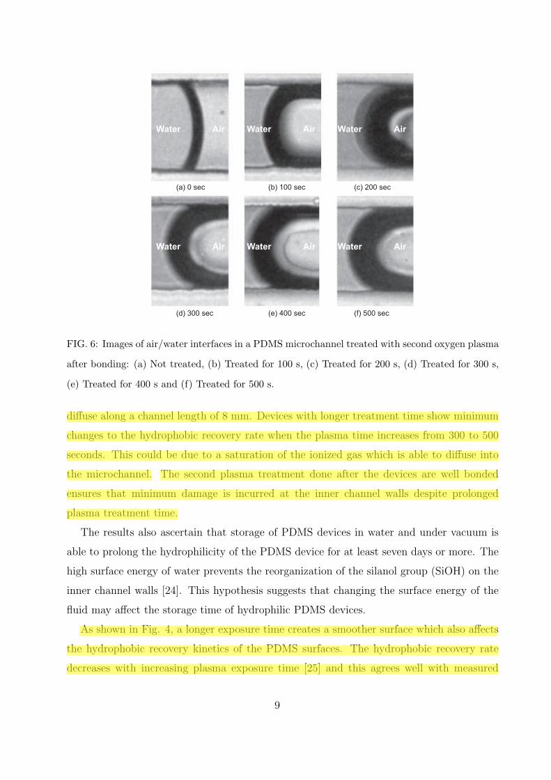
(a) 0 sec (b) 100 sec (c) 200 sec
(d) 300 sec (e) 400 sec (f) 500 sec
Water Air Water Air Water Air
Water Air Water Air Water Air
FIG. 6: Images of air/water interfaces in a PDMS microchannel treated with second oxygen plasma
after bonding: (a) Not treated, (b) Treated for 100 s, (c) Treated for 200 s, (d) Treated for 300 s,
(e) Treated for 400 s and (f) Treated for 500 s.
diffuse along a channel length of 8 mm. Devices with longer treatment time show minimum
changes to the hydrophobic recovery rate when the plasma time increases from 300 to 500
seconds. This could be due to a saturation of the ionized gas which is able to diffuse into
the microchannel. The second plasma treatment done after the devices are well bonded
ensures that minimum damage is incurred at the inner channel walls despite prolonged
plasma treatment time.
The results also ascertain that storage of PDMS devices in water and under vacuum is
able to prolong the hydrophilicity of the PDMS device for at least seven days or more. The
high surface energy of water prevents the reorganization of the silanol group (SiOH) on the
inner channel walls [24]. This hypothesis suggests that changing the surface energy of the
fluid may affect the storage time of hydrophilic PDMS devices.
As shown in Fig. 4, a longer exposure time creates a smoother surface which also affects
the hydrophobic recovery kinetics of the PDMS surfaces. The hydrophobic recovery rate
decreases with increasing plasma exposure time [25] and this agrees well with measured
9

contact angles reported above. However, as the confinement of the channel influences the
result of the plasma treatment, the in-channel surface analysis cannot effectively be compared
with the case of a planar surface. For example, the measured minimum contact angle reached
in our study was 17◦ which is well above the complete wetting condition of less than 10◦
obtained for a planar surface. This difference could well be due to the nature of exposure.
In our case, limited oxygen ions can only enter the channel through the inlets access, while
a planar surface has a direct exposure to the oxygen ions.
IV. CONCLUSIONS
In summary, the concept of producing hydrophilic PDMS devices through the use of a
second extended oxygen plasma treatment after bonding and the storage in DI water under
vacuum condition proves to be feasible. The method reported in this paper can maintain the
hydrophilicity of the devices for several weeks. At 70 W plasma power and treatment time
longer than 300 seconds, the PDMS surface can remain hydrophilic for more than 6 hours
after the exposure to ambient air. The reasonably low contact angle between 50◦ and 60◦
is sufficient for most microfluidic appllications. The time span of 6 hours is also enough for
most experiments in microfluidics. Surface analysis reveals that a longer plasma treatment
time produces a much smoother surface.
Acknowledgements
The authors gratefully acknowledge the support from the Agency of Science, Technology
and Research (A*STAR), Singapore (grant number SERC 052 101 0108 ”Droplet-based
micro/nanofluidics”).
References
[1] J. C. McDonald, D. C. Duffy, J. R. Anderson, D. T. Chiu, H. Wu, O. J. A. Schueller and G.
M. Whitesides, Electrophoresis 21 27-40 (2000)
10

[2] J. C. McDonald and G. M. Whitesides, Accounts of Chemical Research 35 491-499 (2002)
[3] J. Zhou, A. V. Ellis and N. H. Voelcker, Electrophoresis 31 2-16 (2010)
[4] M. Kakuta, F. G. Bessoth and A. Manz, Chemical Records 1 395-405 (2001)
[5] D. C. Duffy, J. C. McDonald, O. J. A. Schueller and G. M. Whitesides, Analytical Chemistry
70 4974-4984 (1998)
[6] G. F. Christopher and S. L. Anna, Journal of Physics D: Applied Physics 40 (2007)
[7] P. Garstecki, A. M. Gan-Calvo and G. M. Whitesides, Bulletin of the Polish Academy of
Sciences: Technical Sciences, 53 361-372 (2005)
[8] Y. H. Dou, N. Bao, J. J. Xu and H. Y. Chen, Electrophoresis 23 3558-3566 (2002)
[9] N. A. Alcantar, E. S. Aydil and J. N. Israelachvili, Journal of Biomedical Materials Research
51 343-351 (2000)
[10] B. T. Ginn and O. Steinbock, Langmuir 19 8117-8118 (2003)
[11] D. T. Eddington, J. P. Puccinelli and D. J. Beebe, Sensors and Actuators, B: Chemical 114
170-172 (2006)
[12] D. Xiao, H. Zhang and M. Wirth, Langmuir 18 9971-9976 (2002)
[13] H. Hillborg, J. F. Ankner, U. W. Gedde, G. D. Smith, H. K. Yasuda and K. Wikstrm, Polymer
41 6851-6863 (2000)
[14] S. Bhattacharya, A. Datta, J. M. Berg and S. Gangopadhyay, Journal of Microelectromechan-
ical Systems 14 590-597 (2005)
[15] R. A. Lawton, C. R. Price, A. F. Runge, W. J. Doherty Iii and S. S. Saavedra, Colloids and
Surfaces A: Physicochemical and Engineering Aspects 253 213-215 (2005)
[16] D. Bodas and C. Khan-Malek, Sensors and Actuators, B: Chemical 123 368-373 (2007)
[17] M. Morra, E. Occhiello, R. Marola, F. Garbassi, P. Humphrey and D. Johnson, Journal of
Colloid And Interface Science 137 11-24 (1990)
[18] A. Toth, I. Bertoti, M. Blazso, G. Banhegyi, A. Bognar and P. Szaplonczay, Journal of Applied
Polymer Science 52 1293-1307 (1994)
[19] J. Kim, M. K. Chaudhury, M. J. Owen and T. Orbeck, Journal of Colloid And Interface
Science 244 200-207 (2001)
[20] I. J. Chen and E. Lindner, Langmuir 23 3118-3122 (2007)
[21] M. Hashimoto, S. S. Shevkoplyas, B. Zaso?ska, T. Szymborski, P. Garstecki and G. M. White-
sides, Small 4 1795-1805 (2008)
11

[22] J. Friend and L. Yeo, Biomicrofluidics, 4 026502-026505 (2010)
[23] M. J. Owen and P. J. Smith, Journal of Adhesion Science and Technology 8 1063-1075 (1994)
[24] L. Lavielle and J. Schultz, Journal of Colloid And Interface Science, 106 438-445 (1985)
[25] H. Hillborg, J.F. Ankner, U.W. Gedde, G.D. Smith, H.K. Yasuda and K. Wikstroma, Polymer,
41 6851-6863 (2000)
[26] A. Y. N. Hui, G. Wang, B.C. Lin and W.T. Chan, Lab on a chip, 5 1173-1177 (2005)
[27] X. Y. Zhu, K. L. Mills, P. R. Peters, J. H. Bahng, E. H. Liu, J. S. Shim, K. Naruse, M. E.
Csete, M. D. Thouless and S. Takayama, Nature Material, 4 400-406 (2005)
[28] A. B. Murphy and C. J. Arundell, Plasma Chemistry and Plasma Processing, 14 451-490
(1994)
12