p ap er submission to journal of computer assiste dt omo ...cis/cista/746/papers/west97.pdf · ap...
TRANSCRIPT

Paper submission to Journal of Computer Assisted Tomography 1
Comparison and Evaluation of Retrospective
Intermodality Brain Image Registration
Techniques
Jay West, J. Michael Fitzpatrick, Matthew Y. Wang, Benoit M. Dawant,
Calvin R. Maurer, Jr., Robert M. Kessler, Robert J. Maciunas,
Christian Barillot, Didier Lemoine, Andr�e Collignon, Frederik Maes,
Paul Suetens, Dirk Vandermeulen, Petra A. van den Elsen, Sandy Napel,
Thilaka S. Sumanaweera, Beth Harkness, Paul F. Hemler,
Derek L. G. Hill, David J. Hawkes, Colin Studholme,
J. B. Antoine Maintz, Max A. Viergever, Gregoire Malandain,
Xavier Pennec, Marilyn E. Noz, Gerald Q. Maguire, Jr., Michael Pollack,
Charles A. Pelizzari, Richard A. Robb, Dennis Hanson, Roger P. Woods
December 9, 1996
Short title: Comparison of Brain Image Registration Techniques.
J. West, J. M. Fitzpatrick, and M. Y. Wang are with the Dept. of Computer Science; B. M. Dawant iswith the Dept. of Electrical Engineering; C. R. Maurer, Jr. is with the Dept. of Biomedical Engineering;R. M. Kessler is with the Dept. of Radiology; R. J. Maciunas is with the Dept. of Neurological Surgery,Vanderbilt University, Nashville, TN.
C. Barillot and D. Lemoine are with Universit�e de Rennes, Rennes, France; A. Collignon, F. Maes,P. Suetens, and D. Vandermeulen are with Katholieke Universiteit, Leuven, Belgium; P. A. van den Elsen,S. Napel, and T. S. Sumanaweera are with Stanford University Medical Center, Stanford, CA; B. Hark-ness and P. F. Hemler are with Bowman Gray School of Medicine, Winston-Salem, NC; D. L. G. Hill,D. J. Hawkes, and C. Studholme are with UMDS, Guy's & St. Thomas' Hospitals, London, U.K.;J. B. A. Maintz and M. A. Viergever are with University Hospital Utrecht, Utrecht, The Netherlands;G. Malandain and X. Pennec are with INRIA, Sophia Antipolis, France; M. E. Noz, G. Q. Maguire, Jr.,and M. Pollack are with New York University Medical Center, New York, NY; C. A. Pelizzari is withUniversity of Chicago Hospital, Chicago, IL; R. A. Robb and D. Hanson are with Mayo Clinic, Rochester,MN; and R. P. Woods is with UCLA School of Medicine, Los Angeles, CA.
Send all correspondence to: J. M. Fitzpatrick, Department of Computer Science, Vanderbilt University,Box 1679 Station B, Nashville, TN 37235, U.S.A. Phone: 615-322-2365. FAX: 615-343-5459. Email:[email protected].
Comparison of Brain Image Registration Techniques 2
Abstract
Objective: The primary objective of this study is to perform a blinded evaluationof a group of retrospective image registration techniques using as a gold standard aprospective, marker-based registration method. In order to ensure blindedness, all ret-rospective registrations were performed by participants who had no knowledge of thegold-standard results until after their results had been submitted. A secondary goal ofthe project is to evaluate the importance of correcting geometrical distortion in MR im-ages by comparing the retrospective registration error in the recti�ed images, i.e., thosewhich have had the distortion correction applied, with that of the same images beforerecti�cation.
Materials and Methods: Image volumes of three modalities|CT, MR, andPET|were obtained from patients undergoing neurosurgery at Vanderbilt UniversityMedical Center on whom bone-implanted �ducial markers were mounted. These vol-umes had all traces of the markers removed and were provided via the Internet to projectcollaborators outside Vanderbilt, who then performed retrospective registrations on thevolumes, calculating transformations from CT to MR and/or from PET to MR. Theseinvestigators communicated their transformations again via the Internet to Vanderbilt,where the accuracy of each registration was evaluated. In this evaluation, the accu-racy is measured at multiple \volumes of interest" (VOIs), i.e., areas in the brain thatwould commonly be areas of neurological interest. A VOI is de�ned in the MR imageand its centroid c is determined. Then, the prospective registration is used to obtainthe corresponding point c0 in CT or PET. To this point, the retrospective registrationis then applied, producing c00 in MR. Statistics are gathered on the target registration
error (TRE), which is the distance between the original point c and its correspondingpoint c00.
Results: This paper presents statistics on the TRE calculated for each registrationtechnique in this study and provides a brief description of each technique and an estimateof both preparation and execution time needed to perform the registration.
Conclusion: Our results indicate that retrospective techniques have the potentialto produce satisfactory results much of the time but that visual inspection is necessaryto guard against large errors.
Index Terms: Medical imaging, image registration, �ducial markers, accuracy val-idation, MR distortion, CT, MR, PET.

Comparison of Brain Image Registration Techniques 3
I. Introduction
All retrospective image registration methods have attached to them some intrinsicestimate of registration error. However, this estimate of accuracy may not always givea true representation of the distance between actual and estimated positions of targetswithin the cranial cavity, i.e., the target registration error (TRE). By using a methodbased on �ducial markers [1], [2], [3] as a \gold standard," and by rendering the �ducialmarkers invisible, we are able to perform a detailed, blinded evaluation of retrospectivetechniques based on their TRE at several landmark locations within the brain.
Two registration tasks were evaluated in this study, CT to MR and PET to MR,and these tasks were broken into subtasks according to the type of MR and to whetheror not the MR image was corrected for geometrical distortion. The image data sets ofnine patients were used, seven of which contained both CT and MR scans, and sevenwith both PET and MR. Spin-echo MR scans of three types were included|T1-weighted(T1), proton-density-weighted (PD), and T2-weighted (T2). Before imaging, each patienthad four markers implanted and a COMPASS stereotactic frame attached. For some ofthe patients, scans were also used that had been corrected for geometrical distortion [4],[5]. The �rst step toward evaluation is the calculation of the \answers": registrationsderived with the aid of the �ducial markers. Next, it is necessary to process the imagesby removing all traces of the markers and the frame in order to ensure that all subsequentregistrations are truly retrospective in nature. We call this process \air brushing."
These air-brushed image volumes were then made available from a central site via theInternet �le transfer protocol (FTP) so that each of twelve other sites could apply its ownretrospective technique or techniques. The resulting transformations were reported to thecentral site by electronic mail. A measurement of error was made by calculating the errorrelative to the gold standard over a set of speci�ed regions known as volumes of interest
(VOIs).
II. Materials and Methods
A. Image Acquisition
All images were stored in 16 bit, two's complement format:� The CT volumes have a resolution in the x and y directions of 512 pixels, and between28 and 34 slices in the z direction. The voxel size is 0.65 mm in x and y, and 4.0 mmin z.
� The MR volumes have a resolution of 256 pixels in the x and y directions, and 20 to26 slices. The voxel size was between 1.25 and 1.28 mm in the x and y directions, and4.0 mm in z.
� The PET volumes have a resolution of 128 pixels in the x and y directions, and 15slices. The voxel size is 2.59 mm in x and y, and 8.0 mm in z.The CT images were acquired using a Siemens DR-H scanner, the MR images using
a Siemens SP 1.5 T scanner, and the PET images with a Siemens/CTI ECAT 933/08{16scanner. For MR, T1, PD, and T2 images were acquired. The T1 image volumes wereacquired with an echo time (TE) of 15 ms and a repetition time (TR) of 650 ms (20 slices)or 800 ms (26 slices), the PD with TE of 20 ms and TR of 2550 ms (20 slices) or 3000 ms

Comparison of Brain Image Registration Techniques 4
(26 slices), and the T2 with TE of 90 ms and the same TR as PD. Readout gradientstrength for T1 was 2.45 mT/m and for PD/T2 was 1.47 mT/m, with four acquisitions inT1 and two in PD/T2. All MR images used half-Fourier reconstruction and a slice selectiongradient of 6.8 mT/m. Three additional MR images were acquired for each patient withthe identical imaging parameters, except that the readout gradient was reversed. For PET,each patient was injected with 10 mCi of 18F- uorodeoxyglucose. Scanning was started40{50 minutes after injection and continued for 25 minutes. Image reconstruction wasperformed using a Hamming reconstruction �lter, resulting in images with a full width athalf-maximum resolution of 9 mm.
Internal Review Board authorization was obtained for the use of the patient data setsin this study. All patients whose images were to be used signed a release form indicatingtheir consent.
B. Geometrical Distortion Correction
We correct MR images for static �eld inhomogeneity by using the image recti�ca-tion technique of Chang and Fitzpatrick [4], [5]. A new image, without inhomogeneitydistortion, is generated from the pair of distorted images acquired with reversed readoutgradients. The MR images are corrected for scale distortion by using the COMPASSstereotactic frame as an object of known shape and size. The scale factors are handled bychanging the voxel dimensions in the image header.
C. Fiducial Markers and Fiducial Localization
Markers are �lled with an aqueous solution designed to be bright in CT and MR.They are constructed from hollow plastic cylinders with an inside diameter of 7 mm andan inside height of 5 mm and attached to plastic marker bases that are screwed into theouter table of the skull of the patient [5], [6]. Markers of an identical construction are usedfor PET scans but are �lled with an aqueous solution of a positron emitter to allow themto be seen clearly in the PET image.
We calculate an intensity-based centroid for each marker using the localization tech-nique described in Wang et al. [6]: we call the determination of this position �ducial local-
ization. This iterative, knowledge-based technique automatically �nds the lowest thresholdsuch that an object formed from voxels whose intensities are higher than the thresholdand that are three-dimensionally connected to a selected voxel is neither too large nor toosmall to be a marker. The large point spread function increases the e�ective size of themarker substantially in PET. The published localization algorithm therefore was modi�edfor this project to take advantage of the e�ective size in determining the centroid in thedirection perpendicular to a slice.
D. Fiducial-based Registration
When we use markers to register images, we call them �ducial markers and call theirpositions �ducial points or �ducials. We register CT to MR, and PET to MR, by calculat-ing the rotation and translation parameters of the rigid-body transformation that mini-mizes the mean square distance between corresponding �ducials in the two images [1],[2]. We have implemented the closed-form solution developed by Arun, Huang, and
Comparison of Brain Image Registration Techniques 5
Blostein [7]. We de�ne the �ducial registration error (FRE) as the root-mean-square (rms)distance between corresponding �ducials after registration and transformation. Marker-based registration was carried out for each patient data set and each MR modality. Thederived transformations were tabulated and used as a gold standard for evaluation of theretrospective registration methods.
E. Removal of Fiducial Markers and Stereotactic Frame
The next step is the removal of all traces of the �ducial markers and the stereotacticframe from each image. We call this process \air brushing." This was achieved by manualoutlining of regions containing these structures, followed by an approximate reconstructionof the image background in each missing region R. In MR, where the background consistsof unstructured noise, pixels at random positions between the edge of R and the lateralimage boundary were sampled and placed in R. In CT, as the outer regions of the imageare comprisedmainly of reconstruction artifacts which take the form of quasi-radial stripes,the approach taken was to interpolate these stripes within the removed region. This wasdone at a given point P in region R by the following method (Fig. 2):
1. Calculate the radial distances e and i of the point P , respectively, from the externaland internal boundaries of the region.
2. Identify points E and I at radial distances e and i, respectively, external and internalto the region. If E lies outside the image, set E to be on the border of the image. Asimilar precaution is taken to insure that I does not lie within the head.
3. Let the intensity at E be Ie and at I be Ii. Assign P 's intensity Ip as Ip = Ie withprobability �, or Ip = Ii with probability 1 � �, where � = i=(i+ e).
A similar technique was used for the PET images; in this case, however, pixels in regionR were set to an intensity value linearly interpolated between the intensity of the internaland external boundaries of R.
This process is illustrated in Figure 3. The top row (Fig. 3a{c) shows slices of originalvolumes from each of the three modalities. The window and level have been set so thatthe background artifacts may be seen. The middle row (Fig. 3d{f) shows the same slicesafter the region R has been outlined and zeroed. This procedure is applied to each slicein the volume. The bottom row (Fig. 3g{i) shows the slices after reconstruction of thebackground in the region R. For the MR case, it can be seen that the replaced areais indistinguishable from the rest of the background. In CT and PET, there are slightdiscontinuities in the direction of the stripes, but the intensity changes smoothly.
For each air-brushed image volume, an ASCII header for each volume was prepared,giving information about the corresponding image, e.g. pixel size, resolution, data formatand acquisition information. The headers conform to the Inter�le standard [8], [9].
F. Communications
After creation of the images and headers was completed, a login name, password, andInternet address were provided to all project participants by e-mail, so that they were ableto transfer the images and headers to their own sites by means of FTP.

Comparison of Brain Image Registration Techniques 6
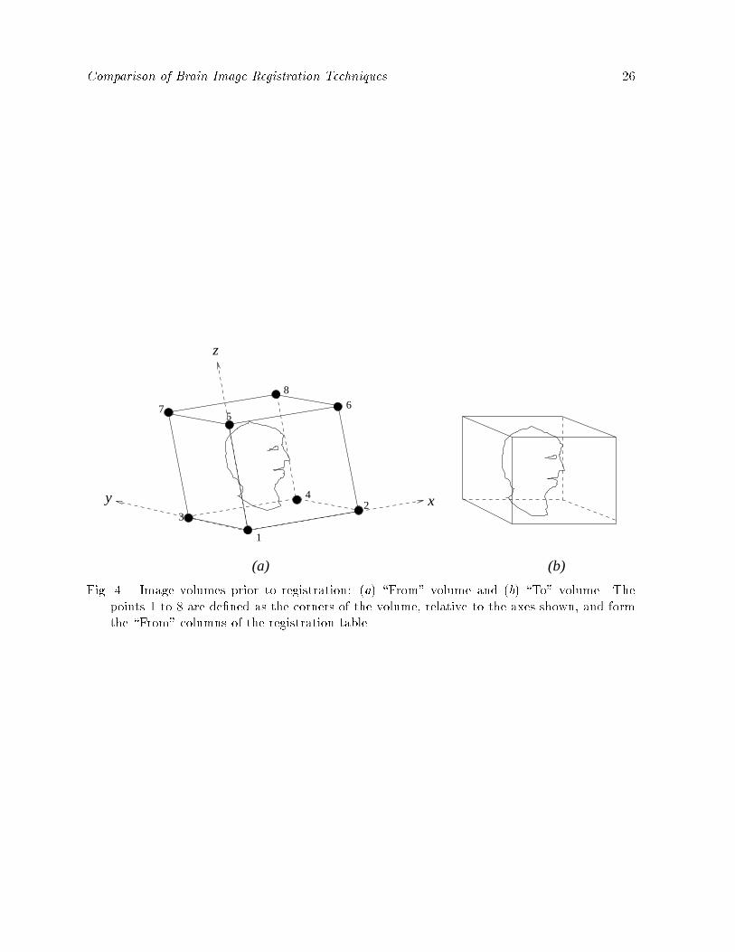
In order to communicate the retrospective registrations to Vanderbilt once they hadbeen completed, the following scheme was adopted. In the \From" volume (e.g., CT inthe case of CT-to-MR registration), the positions of eight points are calculated; taking theorigin to be the center of the �rst voxel in the volume (i.e., the top left pixel of slice zero),the x, y, and z coordinates of the centers of the eight corner voxels in the volume werederived (Fig. 4). These positions were provided via FTP by Vanderbilt for every CT andPET volume in the form of a partially completed \transformation table" for each pair ofvolumes.
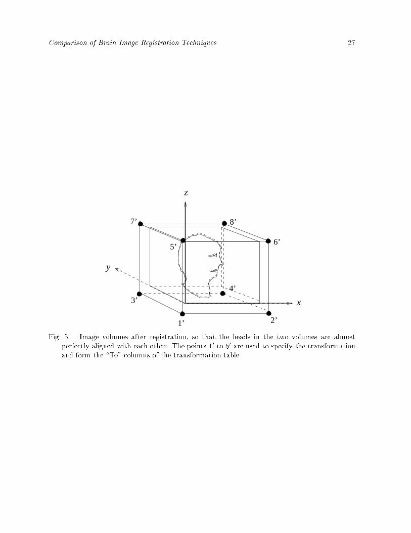
After the retrospective registration transformation was determined, the transformedpositions of these eight points relative to the origin of the \To" modality (Fig. 5) werecomputed by each site and entered into the transformation table (as depicted in Figs. 4and 5, the �eld of view of the two volumes is typically di�erent, so it is important tospecify the volume that provides the origin relative to which the transformed positions arecalculated.)
All coordinates were speci�ed to at least four decimal places in units of millimeters.Such high precision insures that any round-o� error inherent in converting between aregistration transformation and the eight-point sets is negligible. In order to convert thetransformation table to a rigid-body transformation, the two point sets are registered usingthe point-based registration algorithm described in Section II{D. Only three points arenecessary to uniquely specify such a transformation, but the full set of eight was used forreasons of symmetry, error reduction, and error prevention.
Clearly, this method of data transmission allows only rigid-body transformations tobe accurately communicated, since any nonrigid transformation would be approximatedby a rigid one. The use of this protocol thus limits the scope of this project to an evalu-ation restricted to rigid-body transformations. However, by measuring the FRE (that isproduced by the point-based registration algorithm), it is possible to determine whetheror not the retrospective registration uses nonrigid deformations, since the FRE would beon the order of millimeters, as opposed to hundredths of a millimeter, for a well-speci�edrigid-body transformation. This feature is facilitated by the use of a larger point set thannecessary, and guards against the possibility of a nonrigid transformation being mistakenlysupplied and evaluated as if it were rigid.
Each transformation was transmitted to Vanderbilt by e-mailing an ASCII �le con-taining a completed transformation table.
G. The Retrospective Techniques
The retrospective registrations were performed in parallel at several sites outside Van-derbilt. Some methods were used that were applicable only to CT-to-MR or PET-to-MRregistration, and some were suitable for both cases.
1. Barillot and Lemoine [10] used a two-stage technique both for CT-to-MR and PET-to-MR registration. The �rst step is to perform an approximate registration of objectswhich are similar in each image. The second stage is the application of a multireso-lution Powell [11] algorithm which minimizes the Euclidean distance between the twosurfaces given by a 5� 5� 5 chamfer mask. The total time taken for each registration

Comparison of Brain Image Registration Techniques 7
was approximately 15 minutes using a Sun SPARCstation 20.2. Collignon, Maes, Suetens, and Vandermeulen [12] used a fully automatic technique forCT-to-MR and PET-to-MR registration. The technique employs a Powell algorithmto search the space of registration parameters, judging the images to be in perfectregistration when the mutual information of the intensities of corresponding voxels ismaximized. Each registration took 10 to 30 minutes in the CT-to-MR case, and 2 to4 minutes in the PET-to-MR case, using an IBM RS6000/3AT.
3. Van den Elsen, Napel, and Sumanaweera [13] used a fully automated multiresolutiongray-value correlation technique for registering CT volumes to MR. The total timetaken for each registration was approximately 1 to 2 hours using an SGI Indigo 2.
4. Harkness applied a surface-matching technique developed by Pelizzari et al. [14] toCT-to-MR and PET-to-MR registration. The typical time required for each registra-tion was approximately 20 minutes, most of which was human interaction time.
5. Hemler, Napel, and Sumanaweera [15] employed a surface-based method for register-ing from CT to MR. In this system, the corresponding surface to be registered is �rstidenti�ed in each image set. This process results in a triangular mesh representing thesurface in one image set. and a set of 2-D polygon points are used to represent thesurface in the other image set. A least-squares minimization technique is then usedto determine the rigid-body transformation which minimizes a cost function relatedto the sum-square perpendicular distance between the two surfaces. (No estimate ofregistration time was provided by these investigators.)
6. Hill, Hawkes, and Studholme [16], [17], [18] registered CT to MR and PET to MRusing a fully automated multi-resolution voxel similarity measure algorithm based onthe mutual information of the joint probability distribution (proposed by Collignon [12]and Wells [19].) The time taken for each registration was approximately 20 minuteson a Sun SPARCstation 20/61.
7. Maintz, van den Elsen, and Viergever [20], [21], [22] registered CT to MR and PET toMR by matching \edgeness" volumes. The method is fully automated. The algorithmused to match the edgeness volumes is described in [20], [21], [22]. All computationswere done on HP 700-series workstations. For each registration, the feature extractiontypically takes a few minutes. The matching itself can take from 1 to 12 hours forCT-to-MR registration and about 40 minutes for PET-to-MR registration, but thesetimes may be decreased by using larger step sizes and omitting fail-safe measures.
8. Malandain and Pennec [23], [24], [25] registered CT to MR and PET to MR. Themethod was originally designed for PET-to-MR registration and is used for CT-to-MR registration without modi�cation. The �rst step is the segmentation of the brainin both images by means of morphological and topological operators. This is doneautomatically, with human inspection and possible changes in the parameters if asatisfactory result is not achieved. The second step is the construction of a potentialenergy �eld of one volume, and the computation of the global force and torque acting onthe other volume due to this �eld; these values are used to bring the two volumes intoalignment. Each registration took approximately 3 minutes for CT-to-MR registrationand 40 seconds for PET-to-MR registration using a DEC Alpha 3000.

Comparison of Brain Image Registration Techniques 8
9. Noz, Maguire, and Pollack [26] used a two-step method for registration, both for CTto MR and PET to MR. First, an oblique projection, which involves rotating the 3-Ddata set in the coronal and sagittal planes by angles determined by visual inspection, isperformed in order to bring the image slice planes into coincidence. Eight to 12 land-marks pairs are then chosen on a corresponding slice from each image volume, anda �rst- or second-order polynomial (warping) transformation is applied whose coe�-cients minimize the rms distance between the point sets. The time typically requiredfor each registration was between 15 and 30 minutes using a Sun SPARCstation 10/51,most of which was spent �nding corresponding landmarks.
10. Pelizzari [14] used a two-step method for CT-to-MR and PET-to-MR registration.The �rst stage was the segmentation of contours using a combination of manual andthreshold-based boundary following. The contours in the \From" modality were repre-sented as a set of points and in the \To" modality as a stack of disks. The second stagewas the minimization, by means of a Powell algorithm, of the mean square distanceof the points from the surface, measured by �nding the intersection of the surfacemodel with a ray drawn from each point to the centroid of the surface model. Thetypical time taken for each registration was 20 minutes; almost all of this spent inthe segmentation step. The CPU time required for registration was approximately 5seconds on an SGI Indigo 2.
11. Robb and Hanson [27], [28] used a multiresolution, multithreshold, surface match-ing algorithm based on parametric chamfer matching for CT-to-MR and PET-to-MRregistration. Four variations were performed using two di�erent surfaces and twonumbers of points per surface (RO1/RO2 were performed by matching skin to skin,RO3/RO4 by matching brain|or inner surface of skull in CT|to brain; RO1/RO3were performed using 100 points, RO2/RO4 were performed using 1,000 points). Sur-face segmentation was accomplished using an automatic 3-D mathematicalmorpholog-ical algorithm. The total time for each registration on an SGI Challenge workstationranged from 3 to 20 minutes, with morphologic-based segmentation taking 2 to 3 min-utes, manual editing in selected cases taking 10 to 15 minutes, and actual registrationtaking 30 seconds (100 points) to 2 minutes (1,000 points).
12. Woods [29] registered PET to MR using a multi-sampling density method based onthe correlation of intensity values between PET and MR. Two methods were used. Inthe �rst method (WO1), nonbrain regions (i.e., skin, skull, meninges) are manuallyremoved. After this manual editing, automated registration is performed by dividingthe MR image into 256 partitions based on intensity. A Newton-Raphson method isused to �nd the transformation parameters that minimize a weighted average of thestandard deviations of PET voxel intensities corresponding to each MR partition. Thesecond method (WO2) is identical to the �rst except that the MR images are editedmore extensively to remove areas of focal brain pathology. The total time for eachregistration was typically between 20 and 30 minutes using a Sun SPARCstation IPX,with manual editing taking 15 to 20 minutes and cost function minimization takingless than 5 minutes.

Comparison of Brain Image Registration Techniques 9
H. Data Analysis
Each submission of retrospective transformations was accompanied by a statementindicating the cases in which the registration procedure was felt to have failed, i.e., wasnot good enough to be clinically useful. In all cases, the statements indicated that theregistration was successful on every data set provided.
At Vanderbilt, after the transformation tables have been received from each site andthe corresponding rigid-body transformations have been determined, the next step in theevaluation is to perform a comparison between these registrations and the �ducial-basedones. In collaboration with a neurological and a neurosurgical expert, a set of VOIsrepresenting areas of neurological and/or surgical interest was manually segmented withinone of the MR image volumes for each patient. The VOIs were stored as sets of x, y, andz voxel coordinates.
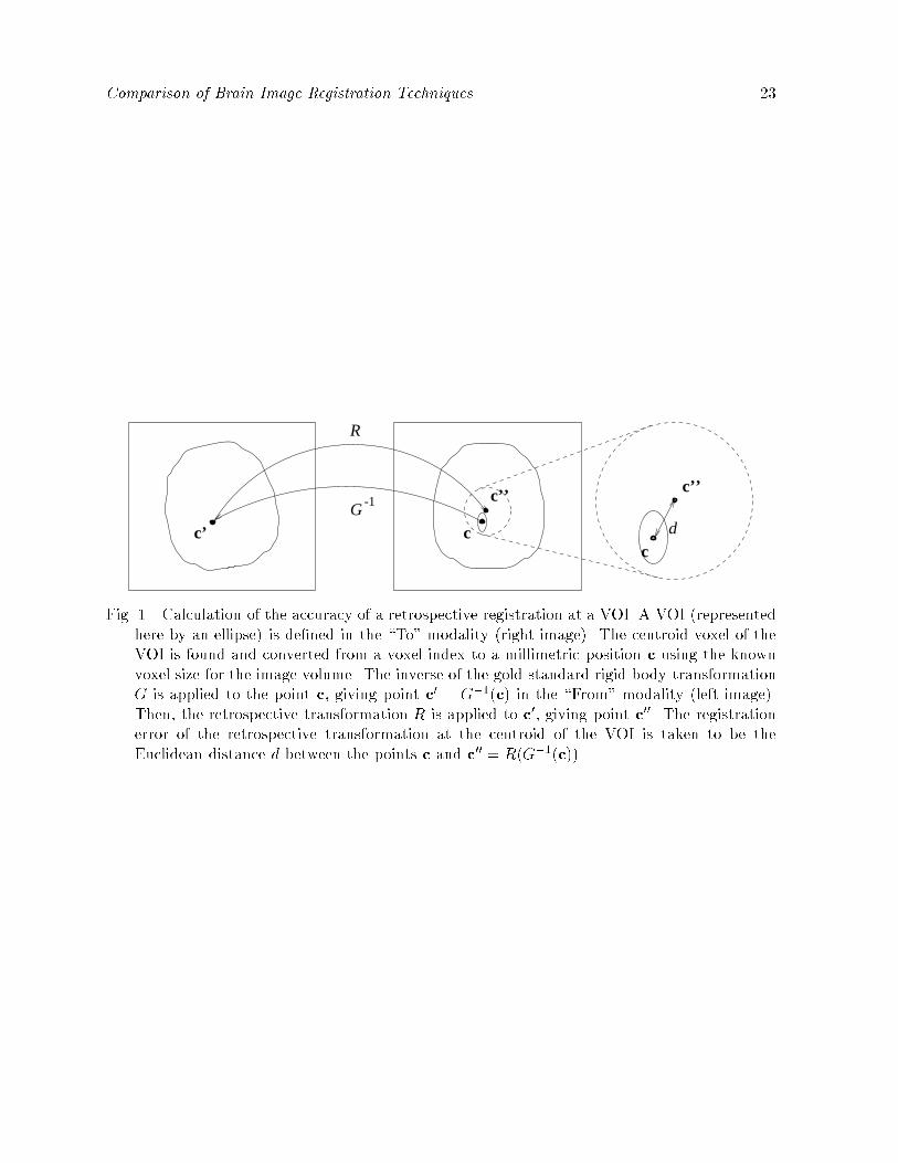
An estimate of the accuracy of the retrospective registration at the position of eachVOI is computed as follows (Fig. 1). The centroid pixel of the VOI is found, and itsposition is converted from a voxel index to a millimetric position c in the \To" modalityusing the known voxel size for the image volume. Let Rg and tg be the rotation matrix andtranslation vector, respectively, of the gold-standard rigid-body transformation G, and Rr
and tr be the rotation and translation components of the retrospective transformation R.The point c0 in the \From" modality is de�ned so that c is the mapping of c0 under thegold-standard transformation. Thus,
c = G(c0) = Rgc0 + tg: (1)
By inverting equation (1), we obtain
c0 = G�1(c) = R
�1g c�R
�1g tg: (2)
The point c00 in the \To" modality is de�ned as the mapping of c0 under the retrospectivetransformation. Thus,
c00 = R(c0) = Rrc
0 + tr: (3)
The di�erence between the registered target position of the retrospective method and thatof the gold standard is d = c
00� c. We de�ne the TRE of the retrospective registration atthe anatomical location of the VOI to be the Euclidean distance d between c and c
00, i.e.,TRE = d = jjdjj.
In Appendix A, we examine the spatial dependence of TRE. If the retrospective trans-formation di�ers from the gold standard by only a translation, then it is easy to see thatTRE = jjtr� tgjj everywhere. For the more common case, in which the di�erence includesa rotational component, the spatial dependence of TRE is only slightly more complicated.We show that TRE exhibits a simple cylindrical symmetry about an axis s running throughthe \To" space as follows:
TRE =par2 + b2; (4)
where a > 0 and b are parameters that are independent of position, and r is the perpen-dicular distance of c from s.

Comparison of Brain Image Registration Techniques 10
Using the formulas in Appendix A, we could calculate a, b, and s for a given retrospec-tive transformation and gold-standard transformation. Large values for a and b and/or alarge distance between s and the center of the image volume would then imply large val-ues for TRE. It is di�cult, however, to translate these values into a clinically meaningfulquantity. Instead, we have chosen to measure TRE directly at a discrete set of centroidsof anatomically meaningful VOIs. While we do not use it in our measurements of TRE,equation (4) still provides an important underpinning for our method of evaluation. Thesmoothness of the simple r2 variation in this equation assures us that our discrete samplingwill not cause us to miss large values of TRE.
The particular anatomical positions corresponding to the VOIs used in this evaluationare as follows: 1) maximum aperture of fourth ventricle, 2) junction of fourth ventriclewith aqueduct, 3) right globe, 4) left globe, 5) optic chiasm, 6) apex of left Sylvian �ssure,7) apex of right Sylvian �ssure, 8) junction of central sulcus with midline, 9) left occipitalhorn, and 10) right occipital horn.
III. Results
For a given technique, the TREs are very similar in all of the VOIs indicating thatthe r2 dependence of equation (4) is masked by variations in a, b, and the position andorientation of the rotational axis s. The similarities are such that we are reporting statisticsonly for the pooled VOIs. A complete listing of the results is available via FTP (see theproject web homepage1).
Tables 1 through 4 present the median and maximum TREs for the CT-to-MR andPET-to-MR registrations. We have chosen to present medians instead of means to reducethe in uence of outliers. The median and maximum TREs listed for each technique andregistration modality pair are the median and maximum of all individual TREs for allapplicable patients and VOIs for that technique and modality pair. Each row represents aregistration modality pair, and each column represents a registration technique. The sitesare represented by abbreviation of the participants' names as follows: 1) Barillot et al.(BA), 2) Collignon et al. (CO), 3) van den Elsen et al. (EL), 4) Harkness (HA), 5) Hemleret al. (HE), 6) Hill et al. (HI), 7) Maintz et al. (MAI), 8) Malandain et al. (MAL), 9) Nozet al. (NO), 10) Pelizzari (PE), 11{14) Robb et al. methods 1{4 (RO1, RO2, RO3, RO4),and 15{16) Woods methods 1 and 2 (WO1, WO2).
We investigated the e�ects of geometrical distortion correction in MR on registrationaccuracy by comparing the CT-to-MR and PET-to-MR registration errors with and with-out correcting for distortion. First, we pooled the results of all registration techniques andused the median TRE values listed in Tables 1 and 3. In all cases the di�erences are notsigni�cant (two-tailed paired t-test, P < 0:05). Second, we examined each technique indi-vidually and used as data for comparison the median TRE values obtained for each patientwith that technique. These di�erences are signi�cant (two-tailed paired t-test, P < 0:05)in only one case: CT-to-T2 registration by Collignon. The di�erences are \marginally" sig-ni�cant (P < 0:10) in four other cases: CT-to-T2 registration by Harkness, and CT-to-T1registration by Collignon, by van den Elsen, and by Hill.
1http://cswww.vuse.vanderbilt.edu/�image/registration/
Comparison of Brain Image Registration Techniques 11
IV. Discussion
The principal goal of this project was to determine the accuracy of retrospective im-age registration techniques. It should be noted that because this study assesses onlyimage-to-image registration, and not image-to-physical space registration, its direct clini-cal application lies in intermodality image correlation. Clinical applications might include,for example, the assignment of anatomic speci�city to functional activation studies withfunctional MR imaging (fMRI) and PET or the longitudinal cross-correlation over time ofimaging studies to follow tumor growth and response to therapy. In using our results toguide such applications it is important to consider the validity of our approach and theaccuracy of our gold standard.
A. Submission Errors
After all transformation tables had been submitted, the gold-standard tables and theoriginal image volumes with visible �ducials were made available so that the correctnessof the evaluation could be veri�ed by all participants. In addition, each site was providedwith error statistics for its technique(s). At this point, the blinded study was over. Afterthis point, four errors were discovered:
� Hill et al. reported that a systematic error was made while converting their transfor-mation format to the Vanderbilt format and submitted revised tables. Speci�cally, Hillstated that the angle of rotation about the x axis was accidentally negated. Vander-bilt independently veri�ed this error, and the error was corrected (noted by the doubledagger in Tables 1 through 4). Because the correction is independently veri�able, theblindedness of the study is not compromised by the inclusion of the corrected data.
� Barillot et al. reported that for one patient the wrong set of tables was submittedfor the recti�ed CT-to-MR registrations. In this case, resubmission would not beappropriate. Instead, the three erroneous transformations were dropped from thestudy (noted by the asterisks in Tables 1 through 2).
� Collignon et al. reported that a manual entry error was made while creating onetransformation table for one patient. Again, resubmission was not appropriate, andthe single erroneous transformation was dropped from the study (noted by the asterisksin Tables 3 through 4).
� Robb et al. reported that for one patient the wrong set of tables was submittedfor the recti�ed CT-to-PD skull-to-brain and PET-to-PD brain-to-brain registrations.In this case, resubmission would not be appropriate. Instead, the four erroneoustransformations were dropped from the study (noted by the asterisks in Tables 1through 4).
We include in Appendix B all results that were obtained before correcting (Hill) or drop-ping (Barillot, Collignon, and Robb) erroneous transformations.
Finally, we note that Maintz et al. withdrew from the study after submitting a partialset of results (CT-to-T1 and CT-to-PD unrecti�ed and recti�ed). After publication ofthe results for the remaining sites [30], this site was permitted to rejoin the study andto complete the submission. Because the gold-standard transformations and the �ducial-containing images were withheld from this site until after the complete submission, the

Comparison of Brain Image Registration Techniques 12
blindedness of the study is not compromised.
B. Gold-Standard Accuracy
The TREs in this study are exact measures of error only if the gold standard providesperfect registration. If the transformation errors of the standard and a retrospectivetechnique are independent, the following simple relationship holds for the rms of theobserved TRE, the true TRE (TREt), and the gold-standard TRE (TREg):
rms[TRE] =qrms2[TREt] + rms2[TREg]: (5)
While we cannot measure rms[TREg] directly, we can estimate it using numericalsimulations [1], [2], [3]. The simulations show that for four �ducial markers rms[TREg] �0:94 rms[FRE]. The rms FRE for marker-based CT-to-MR registration using the threetypes of MR images corrected for geometrical distortion is 0.41 mm. The rms FRE forPET-to-MR registration is 1.75 mm. Thus estimated rms[TREg] is approximately 0.39 mmfor CT-to-MR and 1.65 mm for PET-to-MR. The larger TREs for registrations involvingPET are to be expected because of the larger voxels in this modality.
These simulations do not account for geometrical distortion and therefore apply onlyto the registrations obtained using MR images corrected for geometrical distortion. Thegold-standard TREs can be expected to be somewhat larger for the uncorrected MRimages.
We corrected the MR images for scale distortion by using the stereotactic frame as anobject of known shape and size. The frame N-bar cross-sections lie in the image periphery,where gradient nonlinearity is highest [31], but improvements in the FRE obtained usingour linear scale corrections suggest that the scale factors used in this study improve thegeometrical �delity in the central portion of the images as well. Except for one patient,the scale factors were greater than 1.004 (i.e., 0.4%).
C. Sensitivity Analysis
A preliminary version of this work was presented at Medical Imaging 1996 [30]. Thecurrent version includes results from an additional site (Maintz et al.). The remainingresults di�er slightly from the preliminary ones. The di�erences are due to a di�erence inthe set of VOIs used in the current version. The earlier VOIs were lost in a disk failure.The current VOIs were once again manually outlined for each patient. The statistics inTables 1 through 4 are based on these new VOIs. The mean of the absolute percentagedi�erence in medians between the earlier VOIs and the current ones is 2.9% for CT-MR; forPET-MR, it is 3.5%. These di�erences are small, but they suggest a sensitivity analysis todetermine what aspect of changes in VOIs contributes most to changes in these statistics.
As mentioned in Section II{H, the spatial variation of TRE is smooth, and as men-tioned in Section III, the variation among VOIs is small. To measure the sensitivity toVOI position we perturbed the centroid of each VOI randomly. Our experience in outlin-ing the VOIs suggests that the centroid can vary by as much as one voxel. To simulatesuch variation, we perturbed the current VOIs: in each of 50 runs, the x, y, and z com-ponents of the position of each centroid were altered independently with the displacement

Comparison of Brain Image Registration Techniques 13
of each component chosen from a population with zero mean and a standard deviationequal to one voxel's width in the respective direction (i.e., x, y, or z). The mean of theabsolute percentage di�erence in medians as a result of these perturbations is only 1.5%and 1.3% for CT-MR and PET-MR, respectively, indicating that perturbations of centroidpositions resulting from imprecise drawing of VOIs will not have an appreciable e�ect onthe evaluation.
There is a second less obvious source of variability from the drawing of VOIs. Becauseof some variation in the coverage of the head, some VOIs are absent in some patient imagesand present in others. Furthermore, when drawing VOIs, there is in some cases (near thetop and bottom slices) considerable subjectivity in deciding whether a VOI is present orabsent. Thus, it is likely that a few VOIs have been either dropped or added in the currentwork. The small variation among VOIs observed at the beginning of this section suggeststhat dropping or adding a given VOI will have little consequence. While that may be truewhen the VOI is dropped or added for all patients, the dropping or adding of a VOI fora given patient has the additional e�ect of increasing or decreasing the in uence of thatpatient on the median over all patients and all VOIs. Thus, if the results are relativelymore sensitive to the presence of a given patient, then dropping or adding a VOI or VOIsfor that patient may have a relatively larger e�ect on the median. To investigate thesensitivity to patient selection, we recomputed the medians by dropping patients one byone. We computed the mean absolute percentage change in median over all such patients.The results are 8.9% for CT-MR and 8.1% for PET-MR. These considerably larger changesshow that patient selection may be more important than VOI selection and suggest thatthe observed di�erences between the earlier version and the present one are caused by thedropping or adding of VOIs in a few patients.
It seems clear from this analysis that the selection of patients and patient images canhave an appreciable e�ect on the mean accuracies achieved in a study of this kind. Thusone should be careful when comparing accuracies based on registration results achievedon di�erent data sets.
D. Observations
There is little variation within a given technique of the median and maximum reg-istration error among the three MR types|T1, PD and T2|used in this study. Also,it is clear that the accuracy of registrations involving CT is better than the accuracy ofregistrations involving PET, probably because of the larger slice thickness in PET.
As discussed at the end of Section III, there is a signi�cant improvement in registrationaccuracy after correction of geometrical distortion in MR for only one technique, and a\marginally" signi�cant improvement for four other techniques. We note that a previousstudy found that the mean point-based TRE using three �ducials improved from 1.2 mmto 0.8 mm and the mean surface-based TRE improved from 2.2 mm to 1.2 mm [5]. It ispossible that improvement in accuracy produced by distortion correction is too small tobe seen for many of the registrations in this study.
If a retrospective technique's accuracy is approximately the same as the gold standard,then it follows from equation (5) that the rms of the observed TRE will be approximatelyp2 rms[TREg], which is approximately 0.55 mm for CT-to-MR and 2.33 mm for PET-

Comparison of Brain Image Registration Techniques 14
to-MR. We note that the smallest median values are 0.7 mm for CT-to-MR (Table 1)and 2.0 mm for PET-to-MR (Table 3). The smallest rms values (not tabulated) are1.0 mm for CT-to-MR (Collignon et al., PD recti�ed; Hill et al., T1 recti�ed and PDrecti�ed) and 2.3 mm for PET-to-MR (Woods method 1, T1 recti�ed), suggesting thatthe accuracy of some of the retrospective techniques approaches the accuracy of the bone-implanted �ducial marker method, at least for PET-to-MR registration. Thus, it appearsthat retrospective image registration has the potential of providing satisfactory resultsmuch of the time.
The TRE maxima are often large, however (see Tables 2 and 4), suggesting thatvisual inspection should play an important role in the clinical application of registrationtechniques. If visual inspection reveals a poor registration, then the registration might berepeated (e.g., by using a di�erent initial transformation or by using di�erent registrationparameters), or it might not be used at all. In this study, the option for discardingregistrations was available but was not exercised by any group. Discarding may haveimproved the statistics. For example, one group (Malandain et al.) reported that theiralgorithm was run for all pairs of images with the same parameter settings and withoutvisual inspection. Visual inspection by this group or by any group might have revealedpoor registrations, which could have been declared to be failures and thereby excludedfrom the tables.
Though some registration techniques produced smaller errors than others in this study,it is not possible to draw statistically meaningful conclusions regarding the superiority ofa technique for a given task (or subtask). That was not a goal of this project and, becauseof the large number of techniques (16) and the relatively small number of independentobservations (maximum of seven patients) used in their evaluation, it is not statisticallyfeasible.
We note �nally that Noz et al. performed registration using nonrigid transformations.Our evaluation method approximated their transformations with rigid-body transforma-tions. Thus the results reported in this study may not be a fair evaluation of the accuracyof their technique.
V. Conclusion
Twelve groups of investigators applied 16 techniques to selected registration tasksinvolving the registration of CT and/or PET to MR. Our results indicate that retrospectivetechniques have the potential to produce satisfactory results much of the time but thatvisual inspection is necessary to guard against large errors.
VI. Appendices
A. Spatial Variation of TRE
In this appendix, we derive the spatial variation of TRE, equation (4), for the case inwhich the di�erence between the retrospective and gold-standard transformations includesa rotational component.
We begin by substituting the expression for c0 derived in equation (2) into equation (3)

Comparison of Brain Image Registration Techniques 15
to getc00 = R(G�1(c)) = RrR
�1g c�RrR
�1g tg + tr: (6)
Thus,d = c
00 � c = RrR�1g c� c+ tr �RrR
�1g tg (7)
ord = Rc� c+ t; (8)
where R � RrR�1g and t � tr�RrR
�1g tg. We note that since Rg is an orthogonal matrix,
R�1g = R
tg, where the superscript t denotes transposition.
R can be completely described in terms of an axis of rotation v and an angle of rotation� about v. If we resolve the vectors c and t into their components parallel to (ck, tk) andperpendicular to (c?, t?) v, we have
d = Rc? � c? + t? + tk; (9)
where we have used Rck = ck. If we now �nd the particular value of c?, which we will
call c(0)? , for which
c(0)? = Rc
(0)? + t?; (10)
and de�ne r � c? � c(0)? , we have
d = Rr� r+ tk: (11)
The meaning of this equation is that each d is the result of a rotation about an axis sparallel to v and passing through c
(0)? followed by a translation parallel to s. Taking the
dot product of d with itself gives
d2 = d � d = 2(r � r� r �Rr) + tk � tk; (12)
where we have used r � tk = Rr � tk = 0. Noting that TRE � d, we have
TRE =par2 + b2; (4)
where a = 2(1 � cos �), r = jjrjj, b = jjtkjj, � is the angle of rotation about s, and r is theperpendicular distance of c from s.
B. Submission Error Results
We list here all results that were obtained before correcting (Hill) or dropping (Barillot,Collignon, and Robb) erroneous transformations (see Section IV{A).
� Hill. Table 1 (column HI, row 1 to row 6): 1.6, 2.0, 1.7, 1.2, 1.2, 1.7; Table 2: 3.4, 4.5,4.7, 3.0, 3.4, 4.2; Table 3: 2.9, 3.5, 2.2, 3.2, 3.4, 2.4; Table 4: 8.8, 9.8, 8.3, 9.5, 7.4, 8.6.
� Barillot. Table 1 (column BA, row 4 to row 6): 1.8, 2.0, 2.4; Table 2: 22.0, 39.4, 25.8.� Collignon. Table 3 (column CO, row 4): 3.0; Table 4: 107.0.� Robb. Table 1 (column RO3 to column RO4, row 5): 5.7, 5.8; Table 2: 173.0, 172.9;Table 3: 4.5, 4.3; Table 4: 176.2, 61.6.

Comparison of Brain Image Registration Techniques 16
VII. Acknowledgment
A preliminary version of this work was presented at the conference Medical Imaging
1996 (Newport Beach, CA).Funding for this project was provided by the National Institutes of Health, Project
Number 1 R01 NS33926-02.The Vanderbilt collaborators on this project would like to thank Yu Shyr, PhD for
the time and e�ort he spent advising us about the statistical methods used in this study;John Votaw, PhD (Emory University, Atlanta, GA) for answering many questions aboutPET imaging; and Srikanth Gadamsetty for helping to collect and process patient images.They would also like to thank Nicholas Ayache, PhD (INRIA, Sophia Antipolis, France)and Frederic Fahey, DSc (Bowman Gray School of Medicine, Winston-Salem, NC) fortheir support and encouragement. The investigators from the Mayo Clinic (Rochester,MN) would like to thank Vanessa Murrie for her help in performing registrations. Theinvestigators from New York University Medical Center (New York, NY) would like tothank Elissa Kramer, MD for her help and advice.

Comparison of Brain Image Registration Techniques 17
References
[1] V. R. Mandava, J. M. Fitzpatrick, C. R. Maurer, Jr., R. J. Maciunas, and G. S. Allen, \Registrationof multimodal volume head images via attached markers", Medical Imaging VI: Image Processing,vol. Proc. SPIE 1652, pp. 271{282, 1992.
[2] C. R. Maurer, Jr., J. M. Fitzpatrick, R. L. Galloway, Jr., M. Y. Wang, R. J. Maciunas, and G. S.Allen, \The accuracy of image-guided neurosurgery using implantable �ducial markers", in ComputerAssisted Radiology 1995, H. U. Lemke, K. Inamura, C. C. Ja�e, and M. W. Vannier, Eds., pp. 1197{1202. Springer-Verlag, Berlin, 1995.
[3] C. R. Maurer, Jr., J. M. Fitzpatrick, M. Y. Wang, R. L. Galloway, Jr., R. J. Maciunas, and G. S.Allen, \Registration of head volume images using implantable �ducial markers", Tech. Rep. CS96-03,Department of Computer Science, Vanderbilt University, Sept. 1996.
[4] H. Chang and J. M. Fitzpatrick, \A technique for accurate magnetic resonance imaging in thepresence of �eld inhomogeneities", IEEE Trans. Med. Imaging, vol. 11, pp. 319{329, 1992.
[5] C. R. Maurer, Jr., G. B. Aboutanos, B. M. Dawant, S. Gadamsetty, R. A. Margolin, R. J. Maciunas,and J. M. Fitzpatrick, \E�ect of geometrical distortion correction in MR on image registrationaccuracy", J. Comput. Assist. Tomogr., vol. 20, pp. 666{679, 1996.
[6] M. Y. Wang, C. R. Maurer, Jr., J. M. Fitzpatrick, and R. J. Maciunas, \An automatic techniquefor �nding and localizing externally attached markers in CT and MR volume images of the head",IEEE Trans. Biomed. Eng., vol. 43, pp. 627{637, 1996.
[7] K. S. Arun, T. S. Huang, and S. D. Blostein, \Least-squares �tting of two 3-D point sets", IEEETrans. Pattern Anal. Mach. Intell., vol. 9, pp. 698{700, 1987.
[8] B. S. Baxter, L. E. Hitchner, and G. Q. Maguire, Jr., \A standard format for digital image exchange",American Association of Physicists in Medicine, 1982.
[9] T. D. Cradduck, D. L. Bailey, B. F. Hutton, F. de Conninck, E. Busemann-Sokole, H. Bergmann,and U. Noelpp, \A standard protocol for the exchange of nuclear medicine image �les", Nucl. Med.Comm., vol. 10, pp. 703{713, 1989.
[10] D. Lemoine, D. Liegeard, E. Lussot, and C. Barillot, \Multimodal registration system for the fusion ofMRI, CT, MEG, and 3D or stereotactic angiographic data", Medical Imaging 1994: Image Capture,Formatting, and Display, vol. Proc. SPIE 2164, pp. 46{56, 1994.
[11] M. J. D. Powell, \An e�cient method for �nding the minimum of a function of several variableswithout calculating derivatives", Comput. J., vol. 7, pp. 155{163, 1964.
[12] A. Collignon, F. Maes, D. Delaere, D. Vandermeulen, P. Suetens, and G. Marchal, \Automatedmulti-modality image registration based on information theory", in Information Processing in Med-ical Imaging 1995, Y. Bizais, C. Barillot, and R. Di Paola, Eds., pp. 263{274. Kluwer Academic,Dordrecht, The Netherlands, 1995.
[13] P. A. van den Elsen, E.-J. D. Pol, T. S. Sumanaweera, P. F. Hemler, S. Napel, and J. R. Adler, \Greyvalue correlation techniques used for automatic matching of CT and MR brain and spine images",Visualization in Biomedical Computing 1994, vol. Proc. SPIE 2359, pp. 227{237, 1994.
[14] C. A. Pelizzari, G. T. Y. Chen, D. R. Spelbring, R. R. Weichselbaum, and C.-T. Chen, \Accuratethree-dimensional registration of CT, PET, and/or MR images of the brain", J. Comput. Assist.Tomogr., vol. 13, pp. 20{26, 1989.
[15] P. F. Hemler, T. S. Sumanaweera, P. A. van den Elsen, S. Napel, and J. R. Adler, \A versatile systemfor multimodality image fusion", J. Image Guid. Surg., vol. 1, pp. 35{45, 1995.
[16] D. L. G. Hill, D. J. Hawkes, N. Harrison, and C. F. Ru�, \A strategy for automated multimodalityregistration incorporating anatomical knowledge and imager characteristics", in Information Process-ing in Medical Imaging 1993, H. H. Barrett and A. F. Gmitro, Eds., pp. 182{196. Springer-Verlag,Berlin, 1993.
[17] D. L. G. Hill and D. J. Hawkes, \Voxel similarity measures for automated image registration",Visualization in Biomedical Computing 1994, vol. Proc. SPIE 2359, pp. 205{216, 1994.
Comparison of Brain Image Registration Techniques 18
[18] C. Studholme, D. L. G. Hill, and D. J. Hawkes, \Automated 3D registration of MR and CT imagesof the head", Med. Image Anal., vol. 1, 1996 (In press).
[19] W. M. Wells, III, P. Viola, and R. Kikinis, \Multi-modal volume registration by maximization ofmutual information", in Medical Robotics and Computer Assisted Surgery 1995, pp. 55{62. Wiley-Liss, New York, 1995.
[20] J. B. A. Maintz, P. A. van den Elsen, and M. A. Viergever, \Comparison of feature-based matchingof CT and MR brain images", in Computer Vision, Virtual Reality, and Robotics in Medicine 1995,N. Ayache, Ed., pp. 219{228. Springer-Verlag, Berlin, 1995.
[21] J. B. A. Maintz, P. A. van den Elsen, and M. A. Viergever, \Evaluation of ridge seeking operatorsfor multimodality medical image matching", IEEE Trans. Pattern Anal. Mach. Intell., vol. 18, pp.353{365, 1996.
[22] J. B. A. Maintz, P. A. van den Elsen, and M. A. Viergever, \Comparison of edge-based and ridge-based registration of CT and MR brain images", Med. Image Anal., 1996 (In press).
[23] G. Malandain, S. Fern�andez-Vidal, and J. M. Rocchisani, \Improving registration of 3-D medicalimages using a mechanical based method", in 3rd European Conference on Computer Vision (ECCV'94), 1994, pp. 131{136.
[24] G. Malandain, S. Fern�andez-Vidal, and J. M. Rocchisani, \Rigid registration of 3-D objects bymotion analysis", in Proc. 12th Int. Conf. Pattern Recognition, 1994, pp. 579{581.
[25] G. Malandain, S. Fern�andez-Vidal, and J. M. Rocchisani, \Physically based rigid registration of3-D free-form objects: Application to medical imaging", Tech. Rep. 2453, INRIA, Sophia AntipolisCedex, France, January 1995.
[26] G. Q. Maguire, Jr., M. E. Noz, H. Rusinek, J. Jaeger, E. L. Kramer, J. J. Sanger, and G. Smith,\Graphics applied to medical image registration", IEEE Comput. Graph. Appl., vol. 11, pp. 20{29,March 1991.
[27] H. Jiang, K. S. Holton, and R. A. Robb, \Image registration of multimodality 3-D medical imagesby chamfer matching", Biomedical Image Processing and Three-Dimensional Microscopy 1992, vol.Proc. SPIE 1660, pp. 356{366, 1992.
[28] H. Jiang, R. A. Robb, and K. S. Holton, \A new approach to 3-D registration of multimodalitymedical images by surface matching", Visualization in Biomedical Computing 1992, vol. Proc. SPIE1808, pp. 196{213, 1992.
[29] R. P. Woods, J. C. Mazziotta, and S. R. Cherry, \MRI-PET registration with automated algorithm",J. Comput. Assist. Tomogr., vol. 17, pp. 536{546, 1993.
[30] J. West, J. M. Fitzpatrick, M. Y. Wang, B. M. Dawant, C. R. Maurer, Jr., R. M. Kessler, R. J.Maciunas, C. Barillot, D. Lemoine, A. Collignon, F. Maes, P. Suetens, D. Vandermeulen, P. A.van den Elsen, P. F. Hemler, S. Napel, T. S. Sumanaweera, B. Harkness, D. L. G. Hill, C. Studholme,G. Malandain, X. Pennec, M. E. Noz, G. Q. Maguire, Jr., M. Pollack, C. A. Pelizzari, R. A. Robb,D. Hanson, and R. P. Woods, \Comparison and evaluation of retrospective intermodality imageregistration techniques", Medical Imaging 1996: Image Processing, vol. Proc. SPIE 2710, pp. 332{347, 1996.
[31] L. R. Schad, S. Lott, F. Schmitt, V. Sturm, and W. J. Lorenz, \Correction of spatial distortionin MR imaging: A prerequisite for accurate stereotaxy", J. Comput. Assist. Tomogr., vol. 11, pp.499{505, 1987.

Comparison of Brain Image Registration Techniques 19
TABLE1
M
edian
Errorsfor
CT-to-M
R
Registration
MR
Technique
N
Modality
BA
CO
EL
HA
HE
HIz
MAI
MAL
NOy
PE
RO1
RO2
RO3
RO4
T1
1.6
1.5
1.6
3.4
1.4
1.2
5.1
4.3
3.3
2.7
4.2
5.2
5.7
5.4
7
PD
1.9
1.5
2.0
3.1
2.4
1.9
4.1
4.0
7.8
1.9
4.5
5.5
4.9
4.8
7
T2
2.5
1.5
1.6
4.2
4.7
1.5
3.9
5.0
3.9
2.5
4.5
4.5
5.4
4.7
7
T1rect.
1.4�
0.7
0.9
3.3
1.0
0.7
4.9
5.4
3.4
2.2
5.9
5.9
6.3
5.9
6
PDrect.
1.7�
0.8
1.1
3.0
1.7
0.7
3.0
4.0
4.6
2.1
5.9
5.7
5.5�
5.5�
7
T2rect.
2.1�
0.8
1.6
3.5
1.6
0.8
4.3
5.3
4.2
2.9
5.5
5.3
5.3
5.3
7
Thelabel\rect."indicatesthattheMRimagewascorrectedforgeometricaldistortionbeforeregistration.Seetextfortechnique
abbreviations.�Onepatientomitted.yNon-rigidtransformations.zResultsresubmittedaftergoldstandardreleased.Allerrorsare
inunitsofmm.

Comparison of Brain Image Registration Techniques 20
TABLE2
M
aximum
Errorsfor
CT-to-M
R
Registration
MR
Technique
N
Modality
BA
CO
EL
HA
HE
HIz
MAI
MAL
NOy
PE
RO1
RO2
RO3
RO4
T1
6.4
6.7
6.0
51.8
11.0
2.8
12.8
61.4
10.4
7.3
26.0
21.8
17.8
18.8
7
PD
6.9
3.6
6.6
49.6
10.4
4.1
19.0
59.0
13.9
4.3
25.9
22.2
24.0
20.1
7
T2
9.1
3.4
4.1
50.6
13.6
4.2
6.3
59.5
9.7
7.2
26.7
22.0
19.4
19.8
7
T1rect.
5.8�
3.8
2.6
48.2
2.1
2.3
14.2
60.9
9.6
5.9
27.8
22.2
18.1
18.2
6
PDrect.
5.9�
2.5
5.3
45.9
3.7
2.3
9.9
62.7
11.5
4.6
27.5
22.1
24.9�
20.2�
7
T2rect.
7.4�
4.3
5.2
49.1
14.3
3.0
6.5
63.2
10.2
9.0
27.1
22.5
19.9
21.6
7
SeenotesinTable1.

Comparison of Brain Image Registration Techniques 21
TABLE3
M
edian
Errorsfor
PET-to-M
R
Registration
MR
Technique
N
Modality
BA
CO
HA
HIz
MAI
MAL
NOy
PE
RO3
RO4
WO1
WO2
T1
4.6
3.6
2.8
3.2
3.5
4.2
3.6
2.9
4.0
3.4
2.3
3.1
7
PD
5.2
2.9
4.2
3.1
4.7
4.0
4.1
3.3
4.3
3.3
2.9
3.1
7
T2
4.7
2.8
2.7
2.4
5.3
4.9
4.6
3.3
4.0
3.6
3.6
3.4
7
T1rect.
3.2
2.8�
3.6
2.5
3.9
3.6
3.9
2.8
3.8
3.6
2.0
2.0
4
PDrect.
4.5
3.0
3.2
3.0
4.7
3.6
4.4
2.8
3.6�
4.1�
2.5
2.3
5
T2rect.
3.9
2.0
3.3
2.2
4.0
3.6
5.2
2.9
3.8
3.4
2.5
2.4
5
SeenotesinTable1.

Comparison of Brain Image Registration Techniques 22
TABLE4
M
aximum
Errorsfor
PET-to-M
R
Registration
MR
Technique
N
Modality
BA
CO
HA
HIz
MAI
MAL
NOy
PE
RO3
RO4
WO1
WO2
T1
11.5
12.7
12.1
9.3
10.6
8.5
11.4
10.0
9.4
5.9
5.8
6.0
7
PD
11.2
9.2
10.3
8.1
9.8
9.3
8.9
11.3
8.8
7.1
6.9
6.3
7
T2
12.3
7.5
17.4
8.3
15.0
12.3
7.3
13.4
9.0
7.3
8.4
7.3
7
T1rect.
6.0
3.7�
17.7
6.0
7.7
8.4
14.2
7.9
7.3
8.9
4.2
5.0
4
PDrect.
11.0
7.3
10.1
7.5
9.2
9.4
7.4
11.0
6.6�
6.6�
5.5
5.4
5
T2rect.
9.8
7.1
10.2
9.3
10.9
12.4
11.2
15.2
5.8
7.1
6.0
6.1
5
SeenotesinTable1.
Comparison of Brain Image Registration Techniques 23
-1G
R
c’ c
c’’
c
c’’
d
Fig. 1. Calculation of the accuracy of a retrospective registration at a VOI. A VOI (representedhere by an ellipse) is de�ned in the \To" modality (right image). The centroid voxel of theVOI is found and converted from a voxel index to a millimetric position c using the knownvoxel size for the image volume. The inverse of the gold-standard rigid-body transformationG is applied to the point c, giving point c0 = G�1(c) in the \From" modality (left image).Then, the retrospective transformation R is applied to c0, giving point c00. The registrationerror of the retrospective transformation at the centroid of the VOI is taken to be theEuclidean distance d between the points c and c00 = R(G�1(c)).

Comparison of Brain Image Registration Techniques 24
P
P
E
I
R
i
i
ee
Fig. 2. Calculation of points for interpolation of background patterns in CT and PET images.See text for an explanation.

Comparison of Brain Image Registration Techniques 25
(a) (b) (c)
(d) (e) (f)
(g) (h) (i)
Fig. 3. Removal of �ducial markers and stereotactic frame. The top row (a{c) shows sampleoriginal image slices from CT (a), MR (b), and PET (c). The stereotactic frame (brightcircular spots towards the edge of the image) and �ducial markers (three bright spots nearthe head) are clearly visible in all three modalities. The window and level have been setto show the background artifacts. The middle row (d{f) shows the same image slices afterthe region R has been outlined and zeroed. All trace of the stereotactic frame and �ducialmarkers has been removed. The bottom row (g{i) shows the image slices after reconstructionof the background in the region R. For MR, the replaced area is indistinguishable from therest of the background. For CT and PET, there are slight discontinuities in the direction ofthe stripes, but the intensity changes relatively smoothly.
Comparison of Brain Image Registration Techniques 26
(a)
1
32
4
56
xy
7
8
(b)
z
Fig. 4. Image volumes prior to registration: (a) \From" volume and (b) \To" volume. Thepoints 1 to 8 are de�ned as the corners of the volume, relative to the axes shown, and formthe \From" columns of the registration table.
Comparison of Brain Image Registration Techniques 27
z
x
1’ 2’
3’
4’
6’
7’ 8’
y
5’
Fig. 5. Image volumes after registration, so that the heads in the two volumes are almostperfectly aligned with each other. The points 10 to 80 are used to specify the transformationand form the \To" columns of the transformation table.