p. kofinas and r. e. cohen - apps.dtic.mil · (e) and hydrogenated pi is essentially perfectly...
TRANSCRIPT
AD-A273 683
OFFICE OF NAVAL RESEARCHContuct N00014-91-J- 1045R&T Code 4132047--02-1
Technical Report No. 11
P. Kofinas and R. E. Cohen
Deparntent of Chemical EngineeringMassachuset Insdmrte of Technology
Cambridge, MA 02139403 7 DTICT. -FIJECTE
SDEC1 3 19931".o:;hology of Highly Textured
Polyethylene/ Polyethylene-propyleneSemicrystalline Diblock Copolymer .
Reproduction in whole or in part is permitted for any purpose of the U.S. government.
This document has been approved for public release and sale; its disutibution is unlimited.
o 93-31322
93 12 10 016

BestAvailable
Copy
- SICURIT Y CLASSIFICATION OF THIS PAGE
REPORT DOCUMENTATION PAGEIs. WREPORT SECURITY CLASSIFICATION lb. RESTRICTIVE MARKINGS
a2a. SECURITY CLASSIFICATION AUTHORITY 3. DISTRIBUTION I AVAILABILITY OF REPORT
[ft. DECLASSIFICATION iDOWNGRAOING SCHEDULE
44. PERFORMING ORGANIZATION REPORT NUMBER(S) S. MONITORING ORGANIZATION REPORT NUMBER(S)
11 ONE
66. NAME OF PERFORMING ORGANIZATION 6b. OFFICE SYMBOL 7a. NAME OF MONITORING ORGANIZATION
6C. ADDRESS (City. State, and ZIP Code) (fa a ) 7b. ADDRESS (City, tt, n I Code)
Dept Chem Eng 800 N Quincy StCambridge MA 02139 Arlington VA 22217-5800
Ba. NAME OF FUNDINGI/SPONSORING 8 b. OFFICE SYMBOL 9. PROCUREMENT INSTRUME NT IDENTIFICATION NUMBERORGANIZATION O (f applicable)
ONE
8c. ADDRESS (City. State, and ZIP Code) 10. SOURCE OF FUNDING NUMBERS
800 N Quincy St PROGRAM PROJECT ] TASK ~ WORK UNITArlington VA ELEMENT NO. NO. NO ACCESSION NO
11 TITLE (include Secunriy Classification)
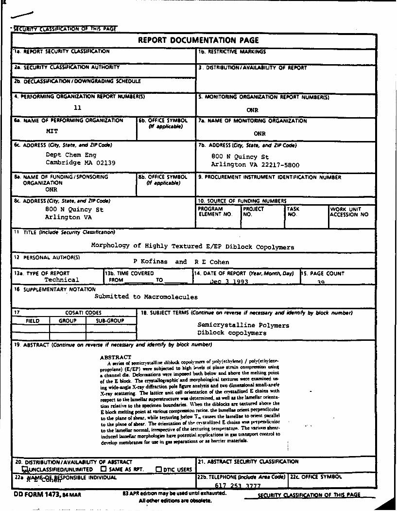
Morphology of Highly Textured E/EP Diblock Copolymers
12 PERSONAL AUTHOR(S) P Ko Ifinas and R E Cohen
13a. TYPE OF REPORT I13b. TIME COVERED 14. DATE OF REPORT (Year. MnthDay) ji5. PAGE COUNTTechnical FROM TO DJec A Q199
16 SUPPLEMENTARY NOTATIONSubmitted to Macromolecules
17 COSATI CODES 18B. SUBJECT TERMS (Continue on reverse if necessary and identify by block number)
FIEL GRUP SB-GOUPSemicrystalline Polymers
Diblock Copolymers
19. ABSTRACT (Continue on reverse if necessary and identify by block number)
ABSTRACTA series of seanicrystalline diblock copolymers of poly(ethylene) / poly(ethvln--
propylene) (E/EP) were subjected to high levels of plane strain compression using& channel die. Deformations Were imposed both below and above the melting pointor the E block. The crystallographic and morphological textures were examined Us-ing wide-angle X-ray diffraction pole figure analysis and two dimensional small-aieleX-~ray scattering. The lattice unit cell orientation of the crystallized E chains withrespect to the larnellar superstructure was determined, as well as the lamellar orienta-"tIo relative to the specimen boundaries. When the diblocks are textured above theE block melting point at various compressioa ratios. the lamellae orient perpendicularto thle plane of shear, while texturing ]below T.. causes the lamellae to orient Parallelto the plane of shear. The orientation of the cr stallizeil E dchains was; Is-rientlicularto the lamellar normal, irrespectiv*e of the texturing temperature. Thle varitous shea-induced lamnellar morphologies have Potential applications in gas transport control todevelop membranes for use in gas separations or as harrier miaterials.
20. DISTRIBUITION JAVAILABIUITY OF ABSTRACT 121. ABSTRACT SECURITY CLASSIFICATION~)NCLASSIFIEDIUNLIMITEID C3 SAME As APT. 0 DTIC USERS ________________________
22& ~A ¶EUhiPONSIBLE INDIVIDUAL 2Z2b. TELEPHONE rInclude Area Code) j22c OFFICE SYMBOL11 617 291 3777 II
DO FORM 1473.s4 mAR 83APR editionmay beused untl exhausted. StRrTY CLSIFICAIN OF 1HIS PAGANl other editions are obsoekte.

Morphology of Highly TexturedPoly(Ethylene) / Poly(Ethylene-Propylene)(E/EP) Semicrystalline Diblock Copolymers
Peter Kofinast and Robert E. Cohen*
t Department of Materials Science and Engineering
"Department of Chemical Engineering
Massachusetts Institute of Technology, 77 Massachusetts Avenue,
Cambridge, Massachusetts 02139
ABSTRACT
A series of semicrystalline diblock copolymers of poly(ethylene) / poly(ethylene-
propylene) (E/EP) were subjected to high levels of plane strain compression using
a channel die. Deformations were imposed both below and above the melting point
of the E block. The crystallographic and morphological textures were examined us-
ing wide-angle X-ray diffraction pole figure analysis and two dimensional small-angle
X-ray scattering. The lattice unit cell orientation of the crystallized E chains with
respect to the lamellar superstructure was determined, as well as the lamellar orienta-
tion relative to the specimen boundaries. When the diblocks are textured above the
E block melting point at various compression ratios, the lamellae orient perpendicular
to the plane of shear, while texturing below T, causes the lamellae to orient parallel
to the plane of shear. The orientation of the crystallized E chains was perpendicular
to the lamellar normal, irrespective of the texturing temperature. Accesion For
NTIS CRA&IDTIC TABUnannounced LIJustification-.........................
=TC QUjALITy rJ7-t,,7 By_.............
1vailabt CoieaI IAvail-andjIorI
|Dist | Special

1. IntroductionIn previous investigations in this laboratory Ill 12], the lattice unit cell orien-
tation with respect to the lamellar microstructure was determined for semicrystalline
diblock copolymers containing an ethylene crystallizable block. The orientation of
the crystallized ethylene chains was found to be perpendicular to the lamellar nor-
mals. This unusual chain alignment was attributed to the influence of interface -
dominated nucleation and topological constraints on growth when the ethylene block
chains crystallize within the amorphous lamellar microdomains present in the het-
erogeneous melt phase of the block copolymers. Bates and co-workers [4] [5] [6] have
studied the lamellar orientation of nearly symmetric amorphous poly(ethylethylene) /
poly (ethylene-propylene) (EE/EP) diblock copolymer samples, which were textured
using large strain dynamic shear. Near the order-disorder transition (ODT) tem-
perature, and at low shear frequencies, the lamellae arrange parallel to the plane
of shear, while higher frequency processing leads to lamellae perpendicular to the
plane of shear. At temperatures further below the ODT the parallel lamellar orienta-
tion is obtained at all shearing frequencies. These interesting and unexpected results
prompted us to enquire into the possibility that semicrystalline block copolymer sys-
tems might also exhibit the perpendicular lamellar morphology under shear.
We have determined the lamellar orientation and chain organization upon
crystallization for various processing histories in a series of diblock copolymers having
crystalline quasi-poly(ethylene) (E) blocks and amorphous poly(ethylene-propylene)
(EP) blocks. Mechanical properties of E/EP diblocks and triblocks have been re-
ported [7] [8], and some work has been done to characterize the morphology [8] [9].
We have previously examined in considerable detail the gas transport properties of the
E/EP polymers used in the present study [10]. Using the results presented below we
demonstrate that changes in the temperature of plane strain compression processing
can be used to force the lamellae to orient either perpendicular or parallel to the plane
of shear; the orientation of the crystallized E chains, however, always remains parallel
to the plane of the lamellar superstructure irrespective of the processing temperature.
2
--
2. ExperimentalThe E/EP block copolymers were synthesized by hydrogenation of
1,4-poly(butadiene) / 1,4-poly(isoprene) block copolymers. The butadiene block con-
sists of 10% 1,2, 35% trans 1,4 and 55% cis 1,4 PB, while the isoprene block contains
93% cis 1,4 and 7% 3,4 PI. The catalytic hydrogenation procedure is described in
detail elsewhere 1111 [12]. Hydrogenated PB thus resembles low-density polyethylene
(E) and hydrogenated PI is essentially perfectly alternating ethylene propylene rub-
ber (EP). The molecular weights of the E/EP diblocks are listed in Table 1. These
values were determined from GPC measurements on the polydiene precursors (first
block and diblock), from knowledge of reactor stoichiometry and conversion, and from
a previous demonstration [11] that little or no degradation occurs during the hydro-
genation reactions. The melting points of the crystallizable E blocks of the series of
E/EP diblocks, were all between 99 and 103 OC, as determined by DSC.
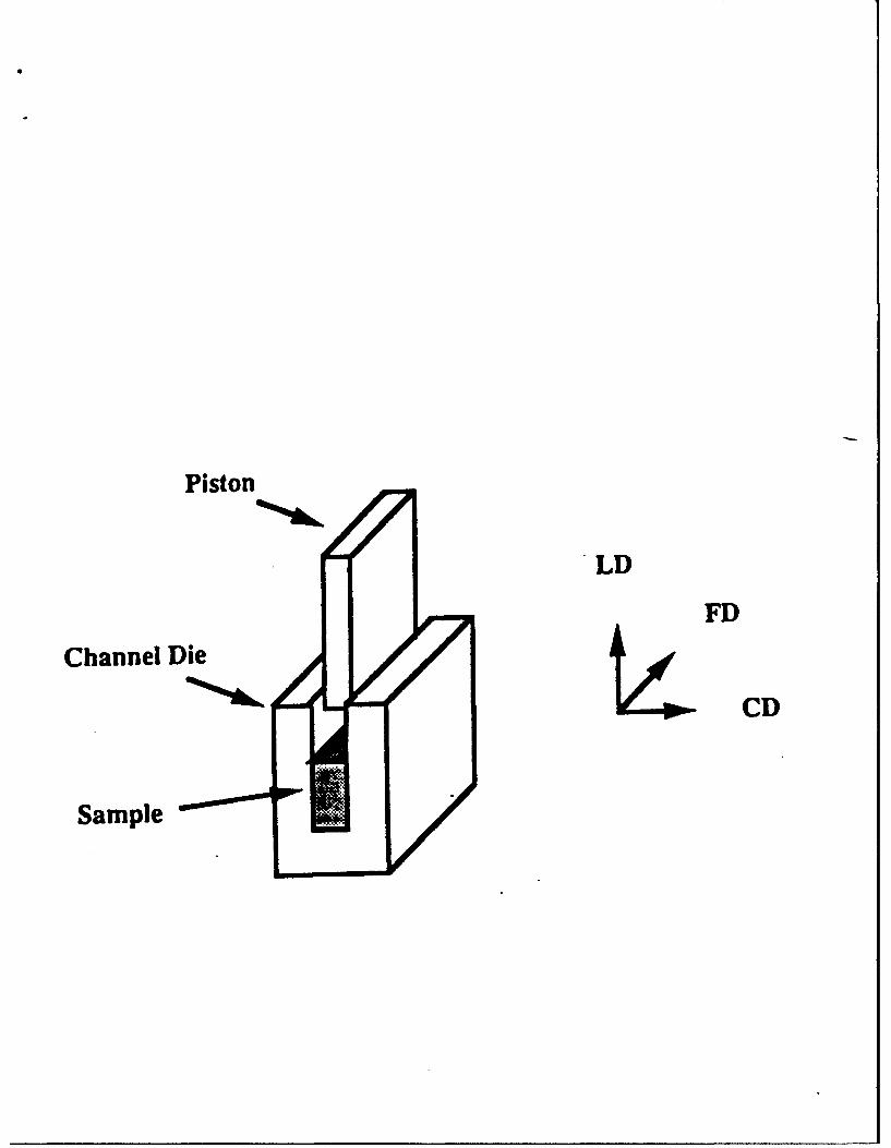
A channel die, the description of which is given in detail elsewhere [13] [14] [15]
[16], was used to subject the polymers to plane strain compression up to compression
ratios of 11. Figure 1 shows a sketch of the channel die and defines the three principal
directions of deformation, i.e., the lateral constraint direction (CD), the free (or flow)
direction (FD), and the loading direction (LD). The channel die was maintained at a
selected constant temperature during the compression flow, and the load was applied
continuously until the desired compression ratios were achieved. The compressed
specimens were quenched under load to room temperature, followed by load release.
The final compression ratio was determined from the reduction of the thickness of
the samples.
The change in lamellar orientation due to deformation was studied by means
of small-angle X-ray scattering (SAXS). The SAXS measurements were performed
on a computer-controlled system consisting of a Nicolet two-dimensional position-
sensitive detector associated with a Rigaku rotating-anode generator operating at 40
kV and 30 mA and providing Cu Ka radiation. The primary beam was collimated
by two Ni mirrors. In this way the X-ray beam could be effectively focused onto
a beam stop with a very fine size without losing much intensity. The specimen to
3

detector distance was 2.7 m, and the scattered beam path between the specimen and
the detector was enclosed by an Al tube filled with helium gas in order to minimize
the background scattering.
A separate Rigaku wide-angle X-ray diffractometer with a rotating anode
source was employed. The Cu Ka radiation generated at 50 kV and 60 mA was filtered
by electronic filtering and a thin-film Ni filter. A Rigaku pole figure attachment was
controlled on-line, and X-ray diffraction data were collected by means of a Micro VAX
computer running under DMAXB Rigaku-USA software. The slit system that was
used allowed for collection of the diffracted beam with a divergence angle of less than
0.30. Complete pole figures [15] were obtained for the projection of Euler angles of
sample orientation: P from 00 to 3600 with steps of 50, and a in the range 00 to 900 also
in 50 steps. X-ray data from the transmission and reflection modes were connected
at the angle a = 500. The specimen orientation was such that the flow direction FD
corresponds to the Euler angles of a = 0*# = 900 or a = 0*0 = 2700 (rotational
symmetry), the constraint direction CD was at a = 0°/8 = 00 or a = 0°# = 1800, and
the loading direction LD was at a = 900 (center of the stereographic projection).
4

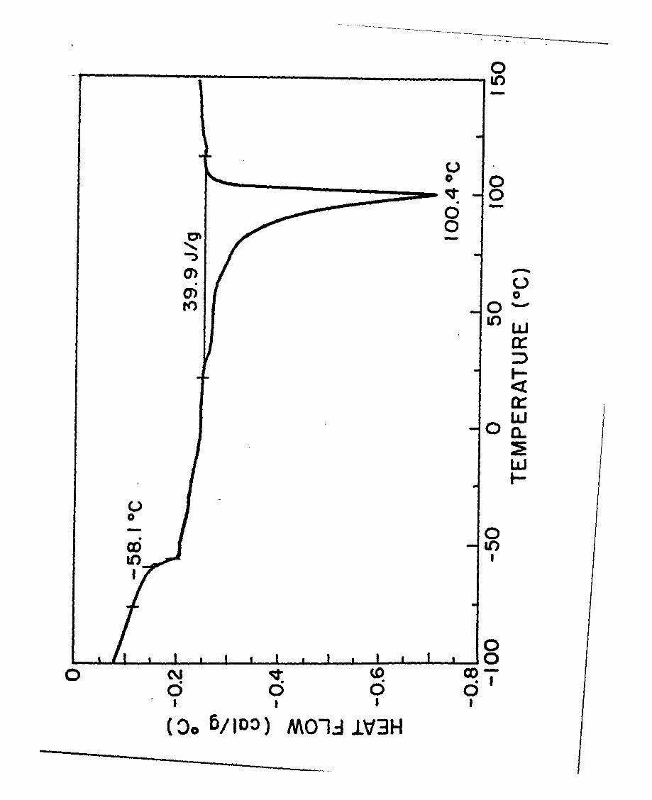
3. ResultsFigure 2 shows the DSC curve for the E/EP 30/70 polymer. The peak
centered at 99 0C defines the nominal melting point of polyethylene in this sample.
The large breadth of the melting curve indicates the presence of a wide distribution
of crystal sizes and perfection. Crystallization occurs almost instantaneously as the
polymers are cooled below their melting point; varying the thermal history has little
observable effect on the degree of crystallinity. Using polarized light microscopy we
observed that all diblocks exhibit spherulitic morphology when crystallized from the
melt, even in the sample containing as little as 30% polyethylene. These observations
suggest that a lamellar morphology predominates over the entire composition range
examined here. A representative micrograph of the spherulitic morphology of the
E/EP polymers is shown in Figure 3.
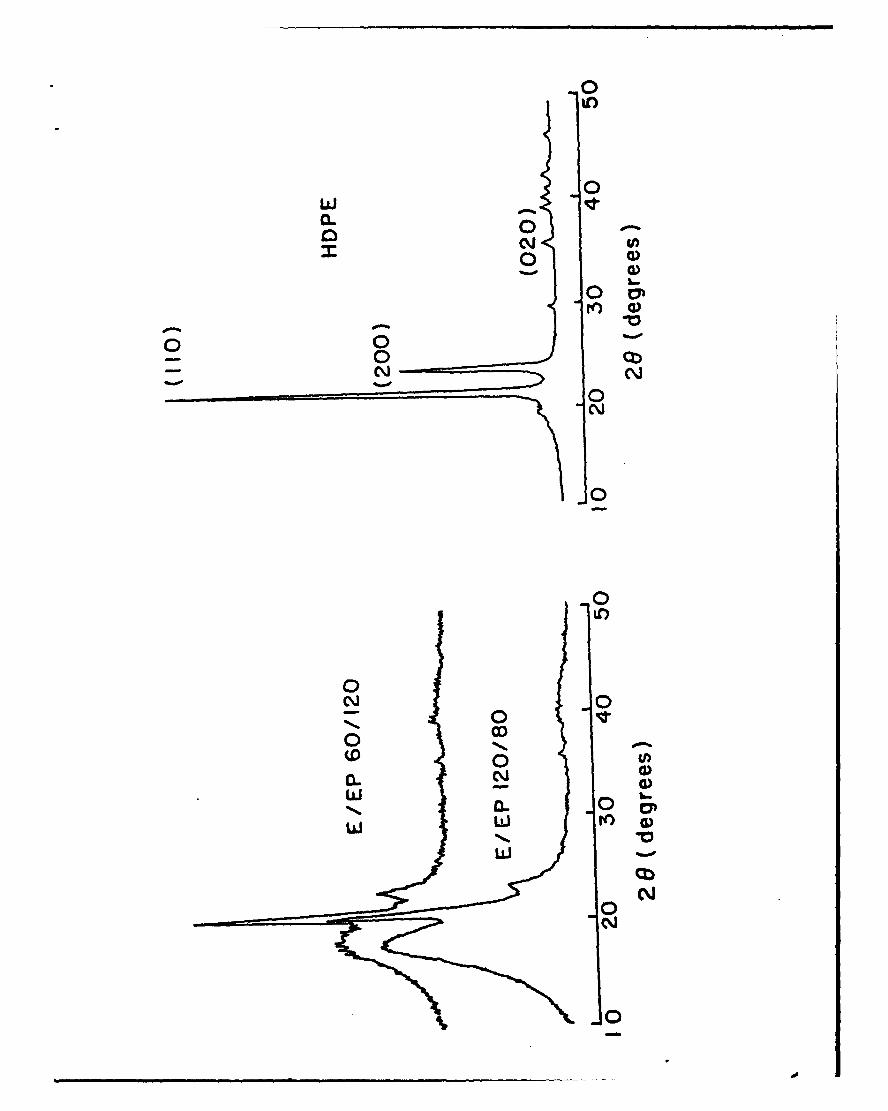
The crystalline structure of undeformed spherulitic E/EP polymers is re-
vealed in Figure 4 in the form of 20 scans from the wide angle diffractometer. The
diffraction peaks observed in the E/EP diblock copolymers correspond to the (110),
(200) and (020) diffraction planes of the orthorhombic unit cell of polyethylene [17]. In
addition to the diffraction planes, a broad amorphous halo centered around 20 = 200
is observed. The intensity of the amorphous halo increases as the amorphous block
content in the diblock increases.
From the positions of the peaks in the 20 scans of the E/EP samples (Figure 4)
it is possible to calculate the a- and b- axis dimensions of the orthorhombic unit cell
using the relationship [17]
1 h k2 12d 2 b ~ 2(1)
where d", is the spacing between crystallographic planes with miller indices h, k and
1, and a, b, c are the dimensions of the unit cell. The values obtained are presented
in Table 1. It is clear that the unit cell of E/EP is slightly larger than that of the
HDPE homopolymer, and that there is no significant trend with amorphous content
or copolymer molecular weight.
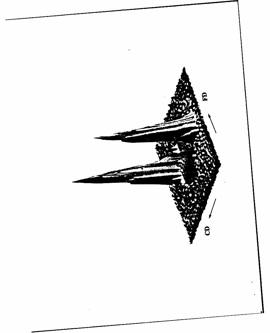
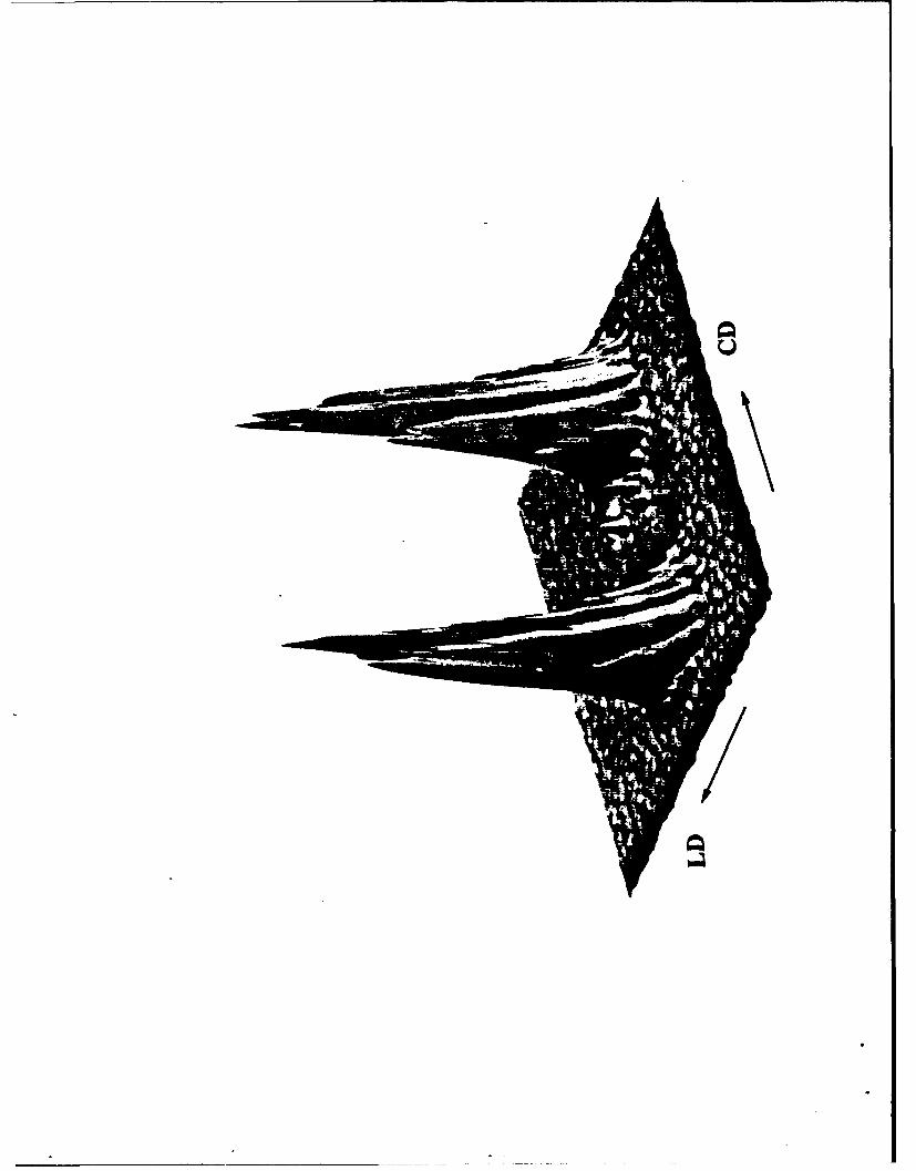
The 2-D SAXS patterns of a representative E/EP specimen subjected to
5
plane strain compression at 150 IC and then quenched to room temperature, are
shown in Figure 5. The channel die experiments were conducted at compression
ratios of A = 4 to A = 12 with no observed change in the SAXS pattern. There is
no significant scattering when the x-ray beam is parallel to the constraint direction;
Spread-out spots on the 2D detector are observed when the sample is irradiated in
the flow direction,in contrast to the sharp dots obtained when the x-ray beam is
along the loading direction. The shape of the FD SAXS pattern is characteristic of
the superposition pattern of lamellar stacks having different amounts of slirar [18].
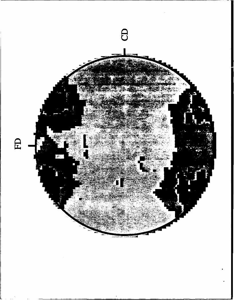
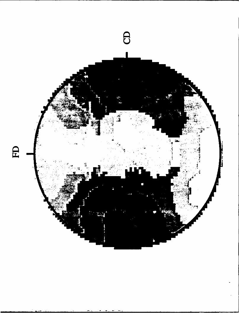
Figure 6 shows pole figures of the spatial density of normals to the (200), (020), and
(110) planes for the same E/EP 50/50 specimen, which was compressed at 150 °C,
i.e. well above the melting point of the E block. The pole figures represent views
from the loading direction, and are shown in the form of shade plots with darker
regions representing higher intensities of plane normals. The (200) and (020) poles
are concentrated along the constraint and the flow direction respectively, indicating
that the chains are oriented in the loading direction.
All diblocks of total molecular weight 1000,000 g/mole exhibited the same
lamellar and chain orientation when textured at 150 0C except for the E/EP 70/30
specimen. The intensity of the scattering in the 2-D SAXS pattern for this diblock was
much lower than the other 100 K specimens, indicating substantially weaker lamellar
orientation, and the pole figure analysis revealed no information on the chain orienta-
tion, since no clustering of poles in any particular direction was observed. The E/EP
diblocks having a large total molecular weight, namely the E/EP 60/120, 120/80,
and 100/100 samples showed no SAXS pattern, when deformed under the same con-
ditions described above; this result arises because the lamellar long periods expected
for these materials are beyond the range of detection in our SAXS equipment.
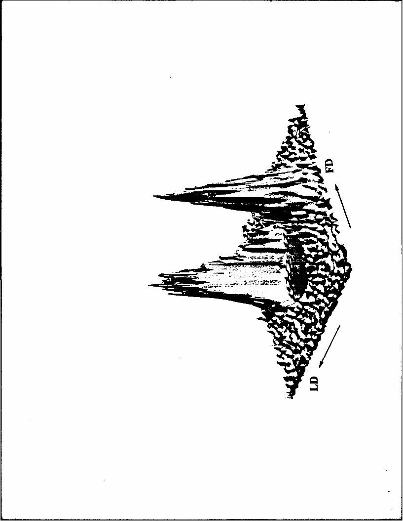
The E/EP 50/50 sample when textured at 80 0C (Figure 7). shows a set of
"SAXS patterns which are completely different form the results (Figure 5) obtained
from the 150 0C channel die compression. The view from the loading direction reveals
no scattering, arcs are observed along the loading direction upon irradiation parallel
to the constraint direction, (Figure 7a) and broad spots are obtained when the x-ray
6
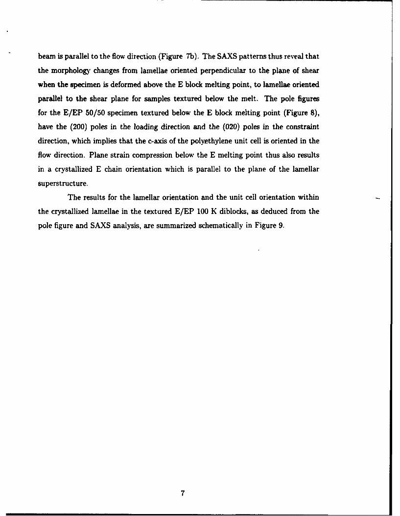
beam is parallel to the flow direction (Figure 7b). The SAXS patterns thus reveal that
the morphology changes from lamellae oriented perpendicular to the plane of shear
when the specimen is deformed above the E block melting point, to lamellae oriented
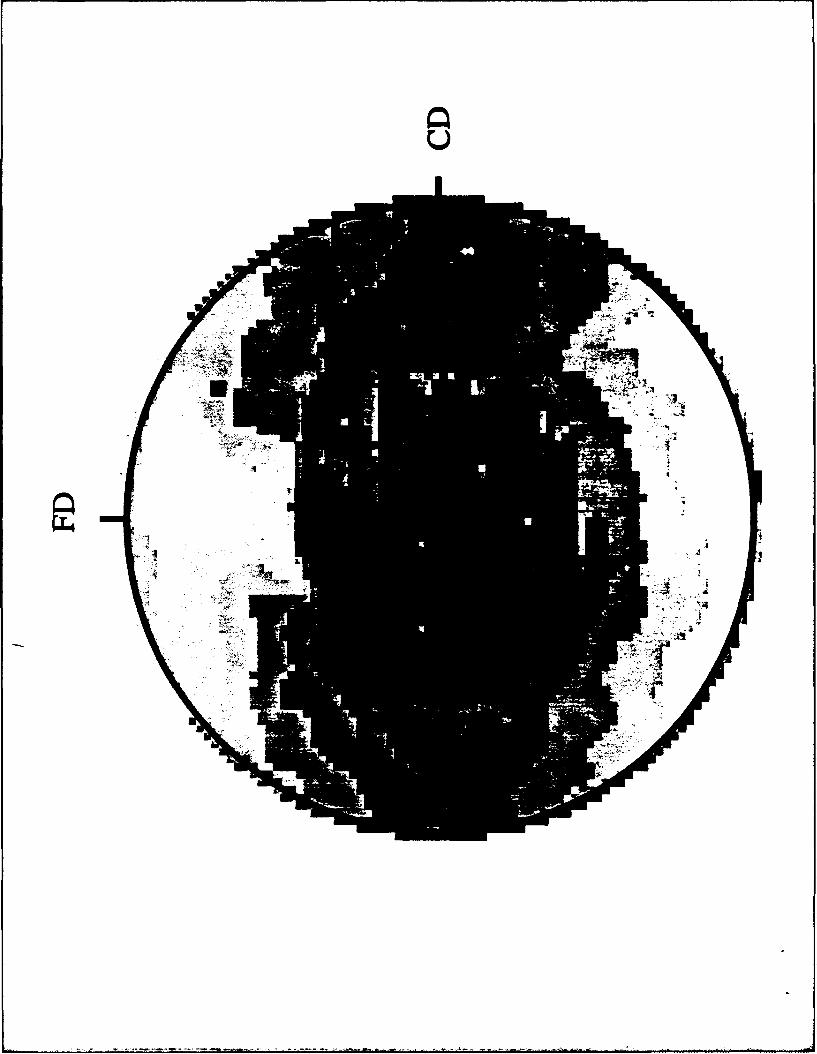
parallel to the shear plane for samples textured below the melt. The pole figures
for the E/EP 50/50 specimen textured below the E block melting point (Figure 8),
have the (200) poles in the loading direction and the (020) poles in the constraint
direction, which implies that the c-axis of the polyethylene unit cell is oriented in the
flow direction. Plane strain compression below the E melting point thus also results
in a crystallized E chain orientation which is parallel to the plane of the lamellar
superstructure.
The results for the lamellar orientation and the unit cell orientation within
the crystallized lamellae in the textured E/EP 100 K diblocks, as deduced from the
pole figure and SAXS analysis, are summarized schematically in Figure 9.
7
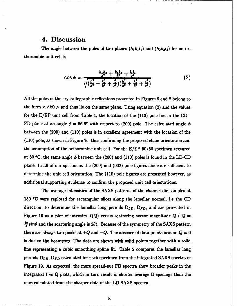
4. DiscussionThe angle between the poles of two planes (h1k,11) and (h2 k212 ) for an or-
thorombic unit cell is
h h k k 171Cos __= _______(2)
All the poles of the crystallographic reflections presented in Figures 6 and 8 belong to
the form < hkO > and thus lie on the same plane. Using equation (2) and the values
for the E/EP unit cell from Table 1, the location of the (110) pole lies in the CD -
FD plane at an angle 0 = 56.6* with respect to (200) pole. The calculated angle 0
between the (200) and (110) poles is in excellent agreement with the location of the
(110) pole, as shown in Figure 7c, thus confirming the proposed chain orientation and
the assumption of the orthorombic unit cell. For the E/EP 50/50 specimen textured
at 80 0C, the same angle 0 between the (200) and (110) poles is found in the LD-CD
plane. In all of our specimens the (200) and (002) pole figures alone are sufficient to
determine the unit cell orientation. The (110) pole figures are presented however, as
additional supporting evidence to confirm the proposed unit cell orientations.
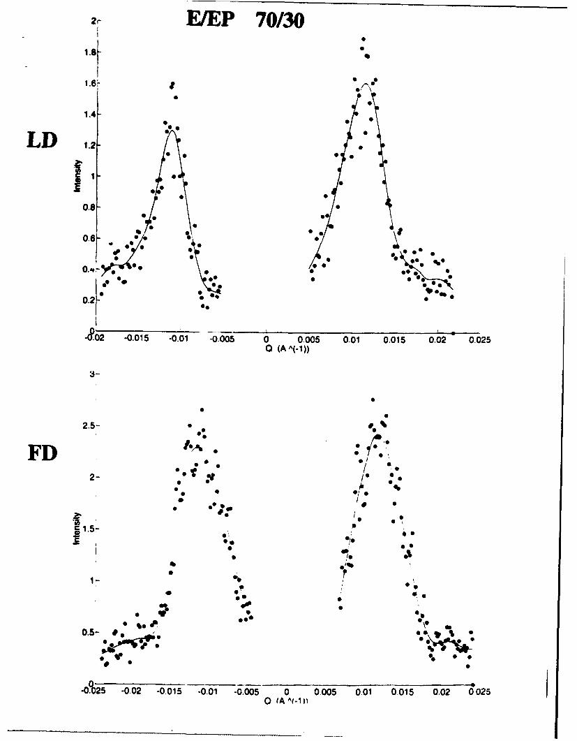
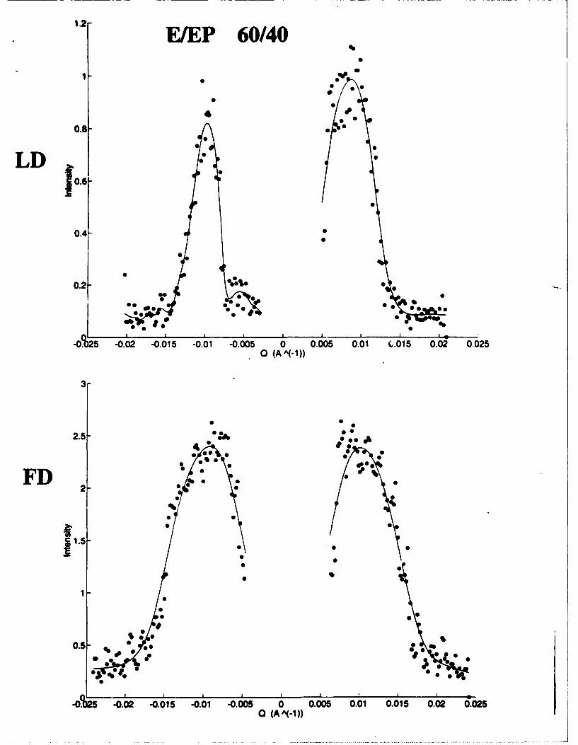
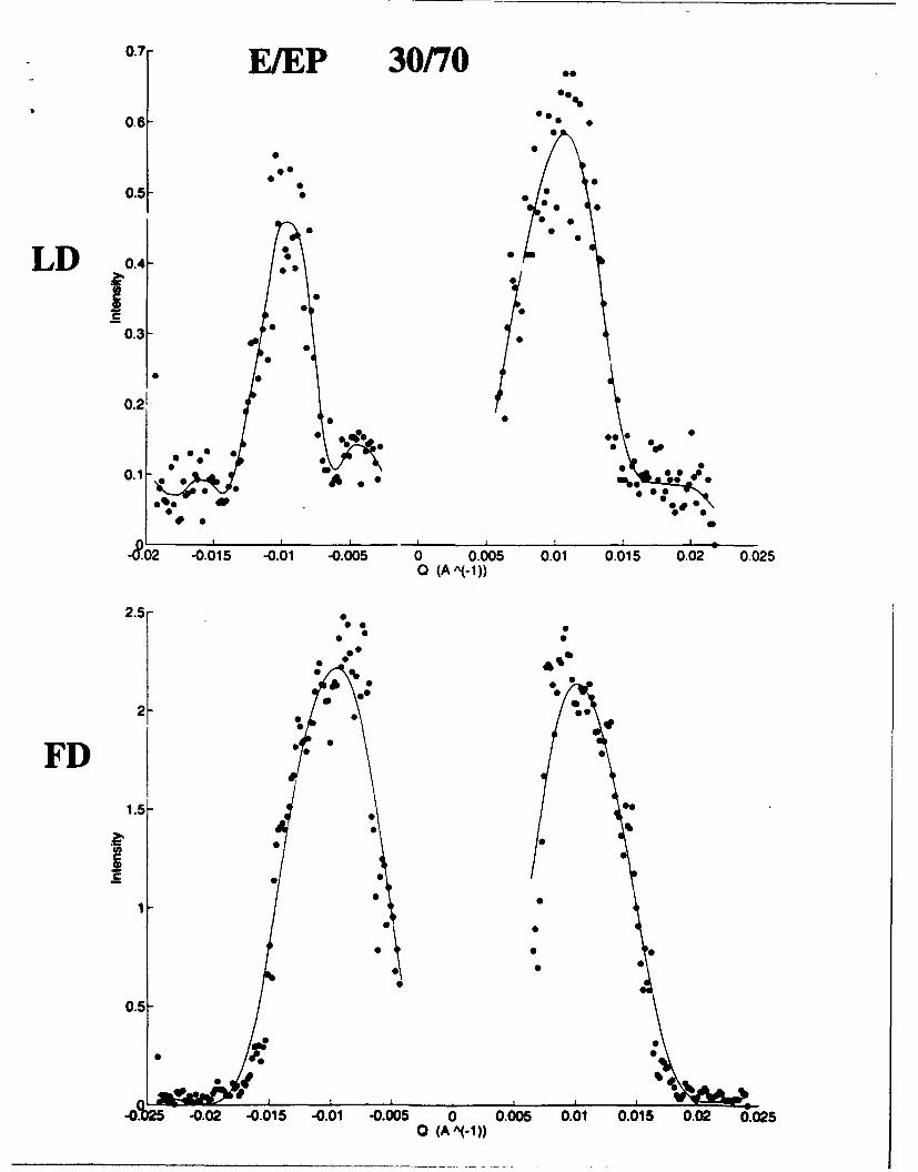
The average intensities of the SAXS patterns of the channel die samples at
150 *C were reploted for rectangular slices along the lemellar normal, i.e the CD
direction, to determine the lamellar long periods DLD, DFD, and are presented in
Figure 10 as a plot of intensity I(Q) versus scattering vector magnitude Q ( Q =
fsinO and the scattering angle is 20). Because of the symmetry of the SAXS pattern
there are always two peaks at +Q and -Q. The absence of data pointq around Q = 0
is due to the beamstop. The data are shown with solid points together with a solid
line representing a cubic smoothing spline fit. Table 2 compares the lamellar long
periods DLD, DPD calculated for each specimen from the integrated SAXS spectra of
Figure 10. As expected, the more spread-out FD spectra show broader peaks in the
integrated I vs Q plots, which in turn result in shorter average D-spacings than the
ones calculated from the sharper dots of the LD SAXS spectra.
8
The behavior of the E/EP diblocks when textured in the melt. can be ratio-
nalized from an examination of the position of the diblocks with respect to Leibler's
phase diagram [19] and using the results of previous studies on wholly amorphous di-
block copolymers [6]. Diblock copolymers contain two long sequences with NA and NS
units of chemically distinct segments. At sufficiently high temperatures (or low total
degree of polymerization NT = NA+NB) the melt is disordered or homogeneous, while
at low temperatures (or high NT) various ordered structures [19](lamellar, OBDD,
hexagonal,cubic) are observed. Equilibrium phase behavior was expressed by Leibler
in terms of the polymer composition f and the reduced parameter XNT, where X rep-
resents the Flory-Huggins segment-segment interaction parameter. XNT for each of
our diblocks was calculated using X values reported by Bates et al [20]; the results are
plotted in the format of Leibler's phase diagram at 100 and 150 0C in Figure 11. The
highest molecular weight diblocks for this study are clearly above the order-disorder
boundary for both of the selected temperatures, thus indicating that at equilibrium
they form heterogeneous melts; the 100 K diblocks, however, are very close to the
order-disorder transition (ODT).
The results shown in Figure 11 show that all of our 1OOK diblocks are being
processed in the 150 0C channel die experiments exactly in the regime near the ODT
in which fluctuations [6] dominate the lamellar structure of the melt. In this regime of
the morphological phase diagram, the diblock copolymers have already been shown to
respond to shear deformation by organizing their lamellar structure perpendicular to
tlhe plane of shear [4]. This peculiar orientation was attributed [6] to the disordering
('melting') of the lamellae with immediate regrowth. The thermodynamic barrier
to disordering was overcome only near the ODT, thus production of perpendicular
lamellae only occurs near the ODT [6]. We find the same behavior here for the case of
plane strain compression of our 100 K specimens at 150 0C. We therefore conclude that
our E/EP diblocks form ordered heterogeneous melts under the shear field imposed
from the channel die, when deformed at 150 0C above the E block melting point.
As the sample is cooled under load the perpendicular lamellar phase is subsequently
'frozen -in' at the onset of crystallization. The crystallization therefore is required to
9
occur in the presence of this pre-existing lamellar morphology, a situiation which has
already been shown [1] [2] clearly to lead to the type of unit cell orientation (chains
perpendicular to the lamellar normals ) shown in Figure 9.
The deformation mechanisms involved in producing the channel die samples
below the E block melting point, which result in a 'parallel lamellar' morphology
, are mostly crystallographic in nature [15], similar to those found in the sub TM
plastic deformation of many polycrystalline materials. The crystallized E chains are
once again always perpendicular to the normals of the lamellar superstructure, but
in this case the crystallographic texture is deformation-induced unlike the interface
dominated crystallization of confined chains mentioned above.
Although the long period spacings of the higher molecular weight samples
precluded direct observation of lamellar orientation for these materials, we still may
conclude that the channel die processing did not produce any oriented lamellar mor-
phology upon plane strain compression at 150 °C of the E/EP 60/120 100/100 and
120/80 diblocks. This statement is based on the absence of any orientation in the pole
figures of these samples. Thus, for the case of semicrystalline block copolymers , the
determination of of the unit cell texture via the WAXS pole figure analysis provides
an added probe for determining what has happened to the material processed in the
melt.
10
5. SummaryWe have shown by SAXS that two distinct lamellar orientations can be pro-
duced when a series of semicrystalline E/EP diblock copolymers of varying E bloc'
content and 100,000 g/mole total molecular weight are subjected to high levels of
plane strain compression. When the diblocks are deformed above the E block melting
point at various compression ratios, the lamellae orient perpendicular to the plane
of shear, while texturing below the melt causes the lamellae to orient parallel to the
plane of shear. The morphology produced above the melting point was attributed to
proximity of the order-disorder transition to the processing temperature. Although
several examples of the unexpected perpendicular orientation have been reported for
amorphous diblock copolymers, to the best of our knowledge this is the first exper-
imental documentation of perpendicular orientation in sheared semicrystalline block
copolymer lamellar phases. The semicrystalline diblocks exhibit the perpendicular
lamellar orientation for a much broader composition range than any amorphous di-
block system reported to date. Furthermore, the semicrystalline systems offer the
advantage that the crystallographic texture, which is eventually locked into the ma-
terials when cooled below Tmn, provides an independent set of clues regarding the
orientation of the lamellae at the point when crystallization takes place. Conversely,
the deformation mechanisms at T < T, which lead to the series lamellar morphol-
ogy, are crystallographic in nature. WAXS pole figure analysis has revealed that the
orientation of the crystallized E chains is perpendicular to the lamellar normal, irre-
spective nf the deformation temperature. When the processing is carried out above
T,, the heterogeneous melt orients perpendicular to the shear planes and then upon
cooling the E block chains crystallize within the amorphous lamellar microdomains,
a process which has been shown to generate a crystallographic texture with chains
perpendicular to the lamellar normals [1] [2].
The unusual shear-induced perpendicular lamellar morphology may have
some potential advantages; for example, it provides a 'parallel' material from the
perspective of transport through a film. We have made use of this structure in an
earlier study [10] of gas transport in these same semicrystalline block copolymers.
11
rhc structure in which the alternating amorphous and semicrystalline lamellae are
oriented normal to the film surfaces enables the membrane designer to enjoy the
structural and thermal stability offered by the semicrystalline regions without having
them interfere with the gas flux through the amorphous lamellae.
In our work to date we have examined only diblock copolymer structures.
Ongoing research includes studies of tri- and tetra- block copolymers of E/EP covering
a wide range of composition and molecular weight.
Acknowledgement. This research has been supported by the Office of
Naval Research and the Goodyear Tire and Rubber Company.
12
References
[1] Douzinas, K. C.; Cohen, R. E. Macromolecules 1992, 25, 5030.
[2] Cohen, R. E.; Bellare, A.; Drzewinski, M. A. Macromolecules, submitted.
[3] Douzinas, K. C.; Cohen, R. E.; Halasa, A. F. Macromolecules 1991, 24,
4457.
[4] Almdal, K.; Koppi, K. A.; Bates, F. S. Macromolecules 1992, 25, 1743.
[5] Koppi, K. A.; Tirrell, M.; Bates, F. S. Phys. Rev. Lett. 1993, 70(10), 1449.
[6] Koppi, K. A.; Tirrell, M.; Bates, F. S.:, Almdal, K.; Colby, R.H. Journal
De Physique II 1993, 2(11), 1941.
[7] Mohajer, Y.; Wilkes, G. L., Wang, I. E.; McGrath, I. E. Polymer 1982,
23, 1523.
[8) Seguela, R.; Prud'homme, J., Polymer, 1989, 30 1446.
[9] Rangarajan, P. Register, R. A.; Fetters, L. I. Blends of Amorphous and
Crystalline Polymers Sympossum, ACS National Meeting, August 1992,
Washington, DC, Division of Polymer Chemistry, Polymer Preprints,
1992, 33(2), Macromolecules, in press.
[10] Kofinas, P.; Cohen, R. E.; Halasa, A.F. Polymer, in press.
[11] Halasa, A. F. U.S. Patent 3 872 072.
[12] Cohen, R. E.; Cheng, P.-L.; Douzinas, K.; Kofinas, P.; Berney, C. V.
Macromolecules 1990, 23, 324.
[13] Lin, L; Argon, A. S. Macromolecules 1992, 25, 4011.
[14] Song, H. H; Argon, A. S.; Cohen, R. E. Macromolecules 1990, 23, 870.
[15] Galeski, A.; Argon, A. S.; Cohen, R. E. Macromolecules 1992, 25, 5705.
13
[161 Gray. R. W.; Young. R. J., J. Mater. Sci 1974, 9, 521.
[17] Spruiell, J. E.; Clark, E. S. Methods of Experimental Physics; Academic
Press: New York, 1980; Vol. 16B, Chapter 6.
[181 Song, H. H.; Argon, A. S.; Cohen, R. E. Macromolecules 1990, 23, 870.
[19] Leibler, L. Macromolecules 1980, 13, 1602.
[20] Bates, F. S.; Schultz, M. F.; Rosedale, J. H. Macromolecules 1992, 25,
5547.
14

sample M X 10- g/mole Unit Cell A*E EP a b
E/EP 30/70 30 70 7.56 4.98E/EP 50/50 50 50 7.53 4.98E/EP 60/40 60 40 7.52 4.96E/EP 70/30 70 30 7.54 4.98HDPE 7.43 4.95
E/EP 60/120 60 120E/EP 100/100 100 100E/EP 120/80 120 80
Table 1: Characterization of E/EP Specimens
15

sample DLD(A*) DFD(AO)E/EP 30/70 618 598E/EP 50/50 601 557E/EP 60/40 665 604E/EP 70/30 556 551
Table 2: Lamellar Long Periods for Channel Die samples at T=150 °C.
16

Figure 1: Channel die apparatus
Figure 2: DSC scan for E/EP 30/70
Figure 3: Optical micrograph E/EP 60/40 crystallized from the melt
Figure 4: WAXS 2-0 scans, E/EP diblocks
Figure 5: SAXS of E/EP 50/50 oriented above the E block melting point via planestrain compression:(a) x-ray beam in the loading direction(b) x-ray beam in the flow direction
17

Figure 6: Pole figures of E/EP 50/50 oriented above the E block melting point viaplane strain compression:(a) (200), (b) (020), (c) (110) planes
Figure 7: SAXS of E/EP 50/50 oriented below the E block melting point via planestrain compression(a) x-ray beam in the constraint direction(b) x-ray beam in the flow direction
Figure 8: Pole figures of the E/EP 50/50 diblock oriented below the E block meltingpoint via plane strain compression:(a) (200), (b) (020), (c) (110) planes
Figure 9: Sketch of lamellar an i unit cell orientation in E/EP specimens processedabove (a) and below (b) the E block melting point
Figure 10: Averaged SAXS spectra for the uniaxially compressed E/EP diblocksabove the E block melting pointLD: x-ray beam in the loading directionFD: x-ray beam in the flow direction
Figure 11: Position of our copolymers relative to the order-disorder transition curve
of Leibler's phase diagram (a) T = 150 °C, (b) T=100 °C
18
Piston
*LD
FD
Channel Die
Z CD
Sample
aoa
0)w
(Oo BIDO)MO-l.LV0

10 gjmI,
0
-0w
0 0
0 0
_ *0
o 0o
- 00- ('4LO
00-0
00
0S%W 0
- 00
a,0og
wl

.16

Uz
u
~lit
Ar•

17U
Id

Al
I Tt,lk
U
'4 4

H I
AHp
m!,)

.0
H.
VmmH
2 -E/EP 70/30
1.4
0.8 -
0.00 0
0 0 0
0.2 0 6
0.72 -0.015 -.010 -0.005 0 0.005 0.01 0.015 0.02 0.0250 (AA(-l))
2-2.5- .
FD t.,. ."~,
0 (AA- 0
* •/... .0/ ,
• 1
1- oS• 0
*/o
0- 6
*o2 00 oi 00 oos a oos 00 0.1 0.2•2
1.2
EIEP 60/40
..8LD •
0.60
0.2-•
0.0I
FD ._ •
0.
0
0 0
0.5,- , - ..0.
j'o~
% 0 0
0.2 0, 0 09* 0 0
% * 0 0 e 000
-o%25 -0.02 -0.015 -0.01 -0.005 0 0.005 0.01 0.015 0.02 0.0250 (A ̂ (-1))

1.6
E/EP 501501.4 *0
0%
1.2 0
100
LD
0.6 -
0.4-
0.2
,01 •" 0 0°
-802 -0.015 -0.01 -o.005 0 0.005 0.01 0.015 0.02 0.0250 (A ^(-1))
2 .5 -
20
0.5 0
,.a 00 0.00
~~00 0
FD •:;
0. 0 .
.25 -0.82 -0015 -0.01 -0.005 0 0.005 0.01 0.015 0.02 0.025
0 (A A(-1))
0.7 E/EP 30/7000%
0.6-@*
0.50
0
0
0.5 0 0
000
0.2
00
0 0000
LD 0.4 :Ii °0.3
0
* 0
0.20& 0
*0 0 0*
00
F00 0 0 e
to0 * %
0 0~ 0
0
o (AA(.1
2.5-
00
* *
00
-.5 -0.02 -0.015 -0.01 -0.005 0 0.005 0.01 0.015 0.02 0.0251 (A A(-1))

T=1 00 C
*50-
40-
Z30-x
20-
10-
0l L0 0.2 0.4 fH)0.6 0.8
T=1 500C
50-
40-
x
20-
10-0
0 0.2 0.4 fH)0.6 0.8