;p-p - nasa
TRANSCRIPT

;P-P (k7/)
NaScR.l 4 2 y7 ) CALIBRATION OF PROPULSIONMSIULATION NOZZLES FOR SPACE SHUTTLE S3
Space Co ) 34 p nC $ 5 CSCL 22B 63 170ncas' ~~ ~__
I

TM 54/20-320LMSC-HREC D225144
LOCKHEED MISSILES & SPACE COMPANY
HUNTSVILLE RESEARCH & ENGINEERING CENTER
HUNTSVILLE RESEARCH PARK
4800 BRADFORD DRIVE, HUNTSVILLE, ALABAMA
CALIBRATION OF PROPULSIONSIMULATION NOZZLES FOR
SPACE SHUTTLE BOOSTER ANDORBITER MODELS FOR THE
ABORT/SEPARATION STAGINGEXPERIMENTAL PROGRAM
July 1971
Contract NAS8-20082
by
L. Ray Baker, Jr.
APPROVED:R V: _ _John W. Benefield, OSupervisor
Fluid Mechanics Section
George D. Reny, Ma agerAeromechanics Dept.

LMSC-HREC D225144
FOREWORD
This document presents the results of work performed by
Lockheed's Huntsville Research & Engineering Center while
under subcontract to Northrop Nortronics (NSL PO 5-09287) for
the Aero-Astrodynamics Laboratory of Marshall Space Flight
Center, Contract NAS8-20082. This task was performed in re-
sponse to the requirement of Appendix B, Schedule Order 178, at
the request of Mr. V. Keith Henson, S&E-AERO-AAV.
ii
LOCKHEED- HUNTSVILLE RESEARCH & ENGINEERING CENTER
LMSC-HREC D225144
CONTENTS
Section Page
FOREWORD ii
1 INTRODUCTION AND SUMMARY 1
2 CALIBRATION TEST DESCRIPTIONS 4
2.1 Model Nozzles 4
2.2 Test Program 5
2.3 Analytical Study 6
3 EXPERIMENTAL AND ANALYTICAL RESULTS 8
3.1 Booster Nozzle 8
3.2 Orbiter Nozzle 9
3.3 Nozzle Setting Curve 9
4 C ONC LUSIONS 12
REFERENCES 13
iii
LOCKHEED- HUNTSVILLE RESEARCH & ENGINEERING CENTER

LMSC-HREC D225144
Section 1
INTRODUCTION AND SUMMARY
One of the primary areas of concern in current studies of the Space
Shuttle configurations is the phenomenon surrounding the abort/separation
maneuver. During this maneuver, the booster and orbiter vehicles are sub-
jected to a combination of aerodynamic and plume gas dynamic effects, the
magnitude of which are a function of vehicle orientation, trajectory conditions
and vehicle main propulsion system power levels. The complexity of such a
problem makes it virtually impossible to assess, analytically, the combined
effects on the individual vehicles. Therefore, an experimental program was
conceived to determine the power-on aerodynamic flight characteristics
of the booster and orbiter vehicles during the abort separation maneuver.
An essential contribution to such a test program is the gasdynamic sim-
ulation of the size and shape of the plumes emitting from the full-scale orbiter
and booster main propulsion systems. The two major effects of the plume
which must be simulated are: the interaction of the plume with the external
flow field, and the direct impingement of the plumes on surfaces which are
enveloped by the plume. The model rocket exhaust plume will produce the
correct effects on the external flow if the model plume is the correct size and
shape and is in the correct location relative to the model configuration. Correct
scaling of the direct impingement of the plumes on surfaces will be obtained,
if in addition to the above, the model exhaust plume matches the momentum
flux per unit area of the full-scale exhaust plume.
To accomplish the objective of correct plume simulation, the similarity
parameters developed by Herron (Ref. 1) and the requirement to match momen-
tum flux per unit area between the model and the full-scale systems, were
applied to the orbiter and booster propulsion systems by Sims (Ref. 2). Wind
tunnel facility requirements dictated the use of air or dry nitrogen ( y = 1.4)
LOCKHEED- HUNTSVILLE RESEARCH & ENGINEERING CENTER
LMSC-HREC D225144
as the working gas (for the model nozzles) and the use of a model sting support
passing through the model base. The necessity of using a gas with a Y different
from the full-scale system resulted in a mismatch in the momentum flux when
the plume size and shape were correctly simulated. Supporting the model with
a base sting system necessitated a large departure from a true scale model
base for both orbiter and booster. A single annular (plug) variable area ratio
conical nozzle placed concentrically around the support sting was selected as
a practical means to achieve plume simulation within the contraints of the test.
The similarity parameters used in the analysis were evaluated at the plume
boundary. Therefore, the use of conical nozzles instead of scaled space
shuttle contoured nozzles should not affect the validity of similarity parameters.
In addition, it was assumed that the similarity parameters apply to plumes
with boundary conditions other than quiescent air (a Newtonian pressure dis-
tribution on the plume boundary,for example. The detailed results of the simu-
lation analysis are presented in Ref. 2.
Two plug nozzle systems have been designed and fabricated to simulate
the multiple nozzle rocket exhaust plume emitting from the booster and orbiter
main propulsion systems during the abort/separation maneuver. The variable
area ratio capability was incorporated into both nozzle systems to permit the
gasdynamic simulation of the full-scale rocket exhaust plume at the various
trajectory conditions of interest.
Calibration testing of the booster and orbiter plug nozzles was accom-
plished in Tunnel C of the Arnold Engineering Development Center's Von
Karman Gas Dynamics Facility (Ref. 3). The nozzles were tested individually
at a series of area ratio settings. Nozzle operating conditions (chamber pres-
sure, Po, and chamber temperature, To ) were maintained in ranges com-
patible with the abort staging test conditions. A quiescent low back pressure,
Pb' condition was maintained in the test cell. Data recorded at each area
ratio setting included: optical data to determine plume shapes; static pressure
measurements on the sting surface at the nozzle exit; nozzle mass flow mea-
surements; and pitot pressure surveys in the plume at several axial locations
downstream of the nozzle exit plane.
2
LOCKHEED- HUNTSVILLE RESEARCH & ENGINEERING CENTER
LMSC-HREC D225144
In a parallel effort, analytical solutions of the nozzle flow field and
associated plume were generated for various area ratio settings of the booster
and orbiter models. A method-of-characteristics solution employing real gas
thermodynamic data for air was utilized in the calculations. Analytical re-
sults for each area ratio setting included: plume shape; static pressure distri-
bution along sting surface; and plots of constant Mach number and constant
pitot pressure contours in the plume flow field. These results formed a base-
line for evaluating the experimentally measured performance of the plug nozzles.
This document presents the results of a detailed evaluation of the nozzle
calibration study. A description of the test hardware is presented, and the
calibration procedures are discussed. Analytical and experimental results
are presented and compared.
3
LOCKHEED- HUNTSVILLE RESEARCH & ENGINEERING CENTER

LMSC-HREC D225144
Section 2
CALIBRATION TEST DESCRIPTIONS
The technical aspects of the calibration tests of the nozzles to be used
in the Space Shuttle abort/separation test are discussed in this section. The
model nozzles are described and the calibration test program outlined. A
discussion of the analytical study conducted in support of the test program
concludes this section.
2.1 MODEL NOZZLES
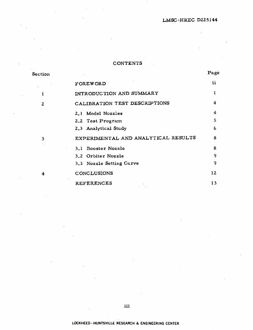
Two "plug" nozzle systems were designed and fabricated to simulate
the multiple nozzle main propulsion systems of the booster and orbiter vehicles.
Each nozzle is designed so that the model vehicle support sting forms the
"plug" portion of the nozzle (Fig. 1). A contoured region on each sting forms
the inner nozzle wall as shown in Figs. 2 and 3. The outer wall of the nozzles
is formed by a sleeve contoured internally. The contoured regions on the
sting and sleeve form a contoured converging/diverging axisymmetric "plug"
nozzle. The sleeve is moved fore and aft axially to change the effective throat
area and thereby change the nozzle area ratio.
A desired nozzle area ratio is obtained by adjusting the outer sleeve
to give the correct axial dimension, Ep, between the nozzle lip and the sur-
face of a reference block. The reference block location is fixed on the sting
surface by a reference pin (Figs. 4 and 5).
The working gas for the. nozzles is room temperature air. The air is
introduced into the nozzle chambers through supply lines that are integral
to the model support sting. Total pressure of the air, Poj, was varied over
a range of 400 to 1300 psia during the test.
4
LOCKHEED- HUNTSVILLE RESEARCH & ENGINEERING CENTER

LMSC-HREC D225144
Actual nozzle dimensions were established by a post-test inspection
conducted by personnel of the MSFC Manufacturing Engineering Labora-
tory. These dimensions are presented in Fig. 4 for the booster nozzle and
Fig. 5 for the orbiter nozzle. In addition, nominal dimensions for each of the
nozzles are included on each of the figures for comparison purposes. The
location of the static pressure port and the reference pin for setting nozzle
area ratio is also specified on each figure.
2.2 TEST PROGRAM
Calibration testing of the booster and orbiter "plug" nozzles was ac-
complished in Tunnel C of the Arnold Engineering Development Center's
Von Karman Gas Dynamic Facility. The objectives of the nozzle calibration
test were:
* Establish, experimentally, nozzle performance characteristics -for the range of area ratio settings to be used with the boosterand orbiter nozzles, respectively.
* Establish a curve (based on experimental results) of nozzle exitconditions as a function of nozzle area ratio setting.
Each nozzle was tested at a series of area ratio settings. The test
procedure consisted of flowing high pressure ambient temperature air
through the nozzle. Data recording was then initiated after continuous,
steady flow was established in the nozzle. Nozzle operating conditions (chamber
pressure, PO., and chamber temperature, To.) were maintained in ranges
compatible with the abort staging test conditions. Tunnel C was operated as
an evacuated test cell. A quiescent, low pressure, Pb, condition was main-
tained in the tunnel during the test program. A summary of test conditions
for the booster and orbiter nozzles is presented in Table 1.
The data recorded at each area ratio setting included:
* Holographic interferograms for determining initial plume boundaryangle and plume shape
5
LOCKHEED- HUNTSVILLE RESEARCH & ENGINEERING CENTER

LMSC-HREC D225144
* Static pressure measurements on the sting surface at thenozzle exit
* Mass flow rate in nozzle supply line using venturi measuringsystem
* Pitot pressure surveys in the plume at specified axial loca-tions downstream of the nozzle exit plane
* Nozzle total conditions, Poj and To
* Test cell ambient pressure, Pb.
2.3 ANALYTICAL STUDY
An analytical study of the booster and orbiter "plug" nozzle configurations
was conducted parallel with preparations for calibration test program. The
objectives of this study were to: (1) establish a baseline for evaluating the
experimental results; (2) provide preliminary information on nozzle performance
characteristics such as thrust and mass flow rate that might affect hardware
design; and (3) provide a rapid means for determining nozzle performance
characteristics (if reasonable agreement is obtained between analytical and
experimental results).
The initial analytical study was conducted using nominal dimensions
(see Figs. 4 and 5) for the booster and orbiter nozzles. Prior to calculating
nozzle performance, it was necessary to determine the variations of nozzle
area ratio with nozzle setting. This was accomplished by calculating the
minimum geometric throat area for each nozzle setting using an automated
technique. The variation of area ratio with nozzle setting are presented in
Fig. 6 for the booster nozzle and Fig. 7 for the orbiter nozzle. This informa-
tion was used to determine nozzle settings for both the calibration tests and
the analytical study.
Nozzle performance characteristics and internal and plume flow field
properties were calculated using Lockheed's variable mixture ratio method-
of-characteristics (VOFMOC) program, Ref. 4. The program was modified
6
LOCKHEED- HUNTSVILLE RESEARCH & ENGINEERING CENTER

LMSC-HREC D225144
to internally shift the nozzle walls to the correct relative position for a specified
nozzle setting (i.e., area ratio). Real gas thermodynamic properties of air
were utilized in the flowfield calculations. The gas properties were calculated
from equations derived from the Beattie-Bridgeman equation of state assuming
variable specific heats, Ref. 5. Flowfield calculations were initiated from
the previously calculated location of the geometric throat using a constant Mach
number start line. Results of these calculations are presented in Figs. 8
through 11.
Following the calibration test program, the analytical calculations were
repeated using actual measured dimensions of the booster and orbiter nozzles.
This information is also presented in Figs. 8 through 11.
A detailed discussion of the results of the analytical and experimental
studies is presented in the following section.
7
LOCKHEED- HUNTSVILLE RESEARCH & ENGINEERING CENTER
LMSC-HREC D225144
Section 3
EXPERIMENTAL AND ANALYTICAL RESULTS
The nozzle performance characteristics of the booster and orbiter nozzles
were evaluated on the basis of comparison of analytical and measured values
of mass flow rate, nozzle pressure ratio, nozzle chamber pressure, and plume
shape information. The experimental and analytical results were correlated
on the basis of nozzle setting, E . Nozzle setting is defined as the measuredp
gap between the nozzle exit lip and the surface of a reference block that is
mounted on the sting during the setting operation. Actual setting of a specific
nozzle gap dimension was accomplished with the use of standard gage blocks
("Jo" blocks) to within +0.0005 in. Figures 6 and 7 show that nozzle area
ratio is extremely sensitive to the setting gap, especially for the orbiter.
Also it is evident from these figures that nozzle dimensions significantly af-
fect the distribution of area ratio with nozzle setting. The degree of success
in obtaining agreement between experimental and analytical results was hinged
directly on actual knowledge of the nozzle dimensions.
3.1 BOOSTER NOZZLE
Performance characteristics of the booster nozzle are presented in
Figs. 8 and 10. The experimental and analytical mass flow rate values shown
in Fig. 8 have been adjusted to a common chamber pressure, Poj, base of
1000 psia for the purpose of comparison. Nozzle pressure ratio data were
determined from the ratio of the static pressure, pj, on the sting surface at
the nozzle exit plane to the nozzle chamber pressure.
In general, both the mass flow and pressure ratio data suggest that the
booster nozzle operates at a lower area ratio experimentally for a specific
nozzle setting than it does analytically. The analytical results obtained with
the measured nozzle dimensions did, however, shift closer to the experimental
8
LOCKHEED- HUNTSVILLE RESEARCH & ENGINEERING CENTER
LMSC-HREC D225144
results. These calculations were run with the same gasdynamic chamber
conditions (Po0 . To ) that were measured experimentally. A comprehensive
review of both sets of data revealed no gasdynamic explanation for the differences
in the test and analytical results.
Because of the difficulty in measuring the nozzle contours, it is suspected
that the actual nozzle dimensions are still not known. In addition, the inspec-
tion results showed that the reference block dimensions and the distance
between reference pin location and nozzle lip at the "reference" condition
vary from the normn enough to contribute to a lack in certainty of the knowledge
of the variation of nozzle area ratio with actual gap setting.
3.2 ORBITER NOZZLE
Performance characteristics of the orbiter nozzle are presented in Figs. 9
and 11. These data were prepared in the same manner as they were for the
booster nozzle data.
Comparison of the analytical and experimental results for the orbiter
nozzle revealed a different trend than was encountered with the booster nozzle.
The initial analytical results (based on nominal nozzle dimensions) fell well
below the experimental results for both mass flow rate and nozzle pressure
ratio. Nozzle performance calculations made using measured nozzle dimen-
sions and calibration test gasdynamic operating conditions were above the
experimental data curves but followed, in general, the contour of the experi-
mental data curve. These results indicate again the dependency of the analyti-
cal calculation of nozzle performance on quality of the knowledge of the nozzle
dimensions. As with the booster, no gasdynamic explanation of the differences
in the experimental analytical results could be determined.
3.3 NOZZLE SETTING CURVE
The disagreement between the experimental and analytical results negated
use of the analytical results to obtain nozzle setting for the abort staging test.
9
LOCKHEED- HUNTSVILLE RESEARCH & ENGINEERING CENTER
LMSC-HREC D225144
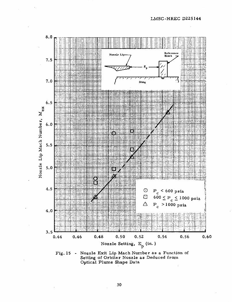
Therefore, experimental data were used exclusively to determine the required
setting curves of nozzle lip Mach number as a function of the nozzle setting.
The basic equations used to determine the desired data can be found in most
gasdynamic texts.
Initially, the Mach number of the limiting Prandtl-Meyer fan is calcu-
lated from the following relation:
72-1
M 2 P
1/2- 1.0] 2
Y2-l(1)
P to.
where: -' is ratio of the ambient back pressure, Pb, to the chamber pres-Pb
sure, P . Using this Mach number and the nozzle half angle, 8 Ns the re-J
sulting turning angle of the flow, V2
is calculated from the following equation:
V2 = ( 2 -l )arctan [1/2
arctan f72+1 (M2 - ) - arctan((M2 - 1)1/2)((
To complete the calculations, the initial plume expansion angle, 6.j, was
determined from the experimental optical data. Examples of these data,
holographic interferograms, are shown in Figs. 12 and 13 for the booster and
orbiter, respectively. Values of 6. were obtained by measuring the initialJ
plume angle directly from the photographs. This information was then used
to obtain one expression for the flow turning angle at the nozzle lip
v1 = Vz -6jV1 2 j
A second expression for V1 was then written as,
10
LOCKHEED- HUNTSVILLE RESEARCH & ENGINEERING CENTER
(3)
(2)
LMSC-HREC D225144
V ( I + 1/21 Vrl
arctan 1 1Y (M2 - ][1 '1 +---
- arctan [(M _ - 1)1 (4)
Combining Eqs. (3) and (4), a function was formed from which the Mach number
at the nozzle lip could be calculated using iterative techniques.
F(M1 ) = (Y 1 -l1 arctan{| [Y (M1 ) -······ Y 1+1 IM
- arctan _(M -]1( -(V 2 - 6)
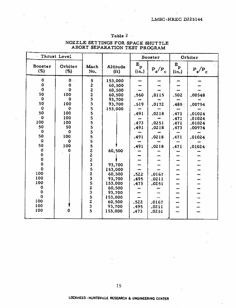
The results of these calculations are presented in Figs. 14 and 15 for the booster
and orbiter, respectively. The curve for the booster was faired through data
that were generally representative of the norm of the nozzle operating condi-
tions. The orbiter data were faired through the points associated with high cham-
ber pressures. This was done to account for the flexing of the nozzle struc-
ture which was noted at these pressures and because the high pressure was
representative of most of the abort staging test conditions. These curves
were utilized with plume scaling information of Ref. 2 to obtain the nozzle
settings shown in Table 2.
11
LOCKHEED - HUNTSVILLE RESEARCH & ENGINEERING CENTER
I
(5)

LMSC-HREC D225144
Section 4
CONCLUSIONS
The following conclusions were reached during the course of the nozzle
calibration study:
* The use of the concept of variable area ratio nozzles for thisapplication is sound and provides a means to satisfy plumegasdynamic simulations over a wide range of conditions.
* The ability to predict analytically the performance of nozzlesof this design and size is associated directly with accurateknowledge of the nozzle dimensions.
* Although, neither the booster nor the orbiter nozzles operatedprecisely as anticipated, the variable area ratio capability per-mitted the simulation criterion to be satisfied.
12
LOCKHEED- HUNTSVILLE RESEARCH & ENGINEERING CENTER

LMSC-HREC D225144
REFERENCES
1. Herron, R. D., "Investigation of Jet Boundary Simulation Parametersfor Underexpanded Jets in a Quiescent Atmosphere, " AEDC TR-68-108,Arnold Air Force Station, Tenn., September 1968.
2. Sims, Joseph L., "Plume Simulation for Space Shuttle Abort StagingAerodynamic Testing, " NASA-MSFC S&E-AERO-AF-70-6, 16 December1970.
3. Test Facilities Handbook, 8th ed., Arnold Engineering DevelopmentCenter, Arnold Air Force Station, Tenn., December 1969.
4. Smith, S.D. and A.W. Ratliff, "User's Manual -Description of theVariable O/F Ratio Method-of-Characteristics Program for Nozzleand Plume Analysis," LMSC-HREC D162220-I, Lockheed Missiles &Space Company, Huntsville, Ala., July 1971.
5. Randall, R. E., "Thermodynamic Properties of Gases: Equations Derivedfrom the Beattie-Bridgeman Equation of State Assuming Variable SpecificHeats," AEDC TR-57-10, Arnold Air Force Station, Tenn., August 1957.
13
LOCKHEED- HUNTSVILLE RESEARCH & ENGINEERING CENTER

LMSC-HREC D225144
Table 1
TEST CONDITIONS FOR SPACE SHUTTLE NOZZLEPLUME CALIBRATION TEST
Inter-Run/Group Configuration Nom. P T E PO fero- Sta.
b o p gram Sta.M (psia) (oF) (in. ) (psia) (in. )
___ __ __ __ __ __ _ __ __ __ __ __ __ __ __ --
- _ __ __ __ _
123456789
1011121313131415161718192021222324252627
2829292930
31
i
Booster
Booster
Orbiter
OrbiterOrbiter
0
0
00
0.36
0.400.400.33
0.340.310.33
0.26
0.260.33
0.330.28
0.28
0.26
0.260.26
100
100
100100100
0.389
0.411
0.426
0.542
0.5420.592
0.452
0.504
0.478
0.512
0.5120.545
0.495
I
505640
500460550550430572
660250450
405330430
1200390485485485485430415
8001200415
I800
12401200800415415800
1200
XX
XXX
X
XXXXX
XXXXXX
XX
XXX
XXXXXXXXX
1.531.533.062.24
1.532.28
1.522.283.03
1.502.280.71
0.71
1.520.710.711.52
0.470.94
0.470.94
0.47
14
LOCKHEED- HUNTSVILLE RESEARCH & ENGINEERING CENTER
L I I I
LMSC-HREC D225144
Table 2
NOZZLE SETTINGS FOR SPACE SHUTTLEABORT SEPARATION TEST PROGRAM
Thrust Level Booster Orbiter
E EBooster Orbiter Mach Altitude p P /Pp(%) (%) No. (ft) (in.) (in.)
0 0 5 153,000 .0 0 2 60,500 - .0 0 2 60,500 . .
50 100 2 60,500 .560 .0115 .502 .005480 0 3 93,700 - - - -
50 100 3 93,700 .519 .0172 .485 .007540 0 5 153,000 - - -
50 100 5 .491 .0218 .471 .010240 100 5 - - .471 .01024
100 100 5 .473 .0251 .471 .0102450 50 5 .491 .0218 .473 .00974
0 0 5 .50 100 5 .491 .0218 .471 .01024
0 0 5 _ . .50 100 5 .491 .0218 .471 .010240 0 2 60,500 - - - -
0 20 20 3 93,700 -
0 5 153,000 - - -
100 2 60,500 .522 .0167 - -
100 3 93,700 .495 .0211 - -
100 5 153,000 .473 .0251 - -
0 2 60,500 - - -
0 3 93,700 .0 5 153,000 - - - -
100 2 60,500 .522 .0167 - -100 l 3 93,700 .495 .0211 - -100 0 5 153,000 .473 .0251 - -
15
LOCKHEED- HUNTSVILLE RESEARCH & ENGINEERING CENTER

I > I I I I I I I I I I I I I I I I
x m o x c z —I
<
33 m en m > 33
o X z o
33
z o o m z H m 33
o»
Booster Assembly
*m
•
<•
Orbi te r Assembly
7 INCHES
Fig . 1 - Nozzle and Sting Assembl ies for the Booster and Orbier Models
g 8
i
K S3 H o D ro i—'

LM
SC
-HR
EC
D
225144
a a o
f o
U N
N
<D
CO
O
O
« 00 • H
17
LOC
KH
EE
D • H
UN
TS
VIL
LE
R
ES
EA
RC
H &
EN
GIN
EE
RIN
G C
EN
TER
LM
SC
-HR
EC
D
225144
C
a 0 o
U N
N
o u
o I
m 60
• 1-1
18
LOC
KH
EE
D - H
UN
TS
VIL
LE
R
ES
EA
RC
H &
EN
GIN
EE
RIN
G C
EN
TER
LM
SC
-HR
EC
D
22
51
44
E-, i-
99Cd
Cd
Wo
Un
ro
o00
m4tn
00
00
-- v
v00
4nt1 '0
.0
Y
U
L=
L=.J
o0u000'
oo,
,.-,o
rRo'- 0
oo o
i
L.J
t 0
t-I
nL1 P
1IC6-
r-Io
L)
FrR If
0r- r-
00L
.J
9010.
02 o0 Qo0
'0L 0.
a.003
+4
,sa
Q 0S
N
i h
0.02
u o_ 0
.a
g
,)0
.4.40
.)
0
, O
m
e,4 0
Jd Q
$440
..n
0) O
Mo
C
a
0+4~
$4u
-N
o
z'r
19
IIIIIII
uW .0
Po r

LM
SC-H
RE
C D
225144
0a,~
~~
~~
~~
~~
~~
~~
~~
~~
~~
~~
~~
,
O4
ha ~~~~aC
d
o ~~~,~
50
~~
~1
~X;,,
, ,o
:~~
~~
~~
~~
r cO am
,~~
~~
~~
~~
~
,~ ,~
boo [4
d
?n
m11_
Tw
~o+
N0
I X
.d
°~ 0
"" E
~~~~~~~~~~~~~~~~~-n
Ln
I~~~~~~~~~~~~~~~~~~~~~~~~~~~~~~~~~
,°° i°
|°t~
~~
~~
~~
~~
~~
~~
~~
~~
~~
~~
~~
-11Z
lM
e|=
["
'r-
["
0
.X~
c
:z:
if o
4-1 .
,Eo
m
'14 cn
4iF4
0 0~b
-4 (d ru
l
0 u
Z~~~~
r -
1
a, 0
0
O
CA
l
N
e~~~~~~~~~d (U
L
U
dycd"c
7D
n,m
t~~
~~
~~
~
d~~
20

LM
SC
-HR
EC
D
225144
O0 r,
N0II
W1 In21:
N$
o N
.3
0
E
a
tn o
o oo
a C
)
"i -
z
o u(
In~
~
0 4)~~S.'C'0
E
o SDU
4
NNZ
acn
0 0
0 _ 00
0 0
N
N
--
o 9'
o N
0
w
1o N
4
olle
N
tea.v
21
LM
SC
-HR
EC
D
225144
EEEER~qRM--
T
.. ... ...
... t_ _
I ..i... !... .!...1. 1.L
..: ... .2: !: ..: i. :..i:
:~.
I_ .
l +
t__
__._
_
L .'.. --·i:-i--1 -i -:t -
I
CI~
~~
~I
14+H
DC
r
tI . I1
-i-4 -F.
TF-F i
j..
i'
I I
I I
I :1
i9 a
a
I-' : 1: 1 1:. 1: i-1: I
I I> --
1.--+ .-
i -1
1L .
:: : :'':
LL §4+27K
_ I.
r7_.
, 4 ..
FI-. ,
:j7idr 7O
]4.-
iI: e
.-o
Y"
1 :::
-04-
Q-E
0404044
'duU%
2e: .
...--U
--l-l .
:--°
-- c:
-.: .
-1 -i-1
- :1
- ..
.'
., ..
i ::Iz
:X
Lo
t mtT tltt-
-L
| tt-A
x i
<
4 s
1 7 -L7
7 -7-
ap.~
~~
~~
~~
~*.
F7
D~
~~
~~
~~
~~
~~
~~
~~
_
_:1 --I I -l --.
fL-i--1H i
-lf-l-t S-
z~
~~
~~
T
LL
-L
~
tW
¢$12X
t-: f X
< I i: ::i-i;ii
| | :| rF P
i l
ST
l 1
i X o@ n tX l| ? 00-1t H A
: 1 : : : t -- X -
-: j
:W
..L 4 e
<
1 -1
] 101 !:i: .: +
iI ::
:r z
: --i-
ta
w·r
-··: :l:i l:: · l i : i iili lsli
I 1 11 ;rl
Ij-la 11 t~ -~-l -- ~---N
l-
o!lle
Hei
0.4
iZ
N00 ov ooDoc
C3rro.n
0
C
40
iE
o -
o 0
o.00
0
I a)
U
1.0
0
I
C4
N
NN0~
I Z04
n 4
o
o _
e
J N
n
S
.- U
I-I N
o 3 N
0
n 0O
I 0
,at
Io
0
o
rr-.00b
40
iz
40CL
40
.zID04
jco100
oO
O
O
o
o o
o O
o
oo
0 0
0 00
0 C
a
0 0
O
c 0
0 0 O
O
O
O
o'
P
r- o
un 40
-o N
_
,.,.. i
.l .l.l.l..l.
l .-l- l
,- :E 1 t
-e 1S
-- 4-4-T---1
_ i ;
1 :T
iiii ................... _ i' _
! ;i ..
,.... ..............r'irt
i ';
' ;S
1||2
'' ...
': 'j''.,1
1'!: -. _.. _
.. 0
1 .
: |-r :,<'
F _11.''_
LA
_
1~
~~
~i
i. 1.
::1 1 S1. S:
1' 1 '' 1 1
: 1 S 2<
i~:i _
Lft l):
: .1
'1'::1
-77-.1::.z�VIT0",-1 � Z.-1,
la-l
,,:, ,i
,.i .... .L
.,,i t i .,.:
'.
aII
1--.
iL
:TiL:l
F7=7.7.. +
.,
[.4-1-

LM
SC
-HR
EC
D
225144
co4)
Uoo
0U)j,
O a
1-'
Cd M
'
¢>
44,-
h
.4-
r11 ;lr
l;g
-dj
jig rC]
vl ~d j : 1
ri'~VkI·c
jolir !I~~~d
kO
.--- -
tIL -iiii ,
'1- !
L
'-' 1"'
h r
|
h i
IUt
7 144J'W
i I1
I4;
11
B3111E
K
_I
;I, 4
.-. -,
'*U
, ,,:
·:11 I-i Ji-
iiS: 1H S
X X
U
.
H
.C
l m
i
Wf
utii W
W
ffi i
0i i
t
fine i :
~~~it W
hwwg
|:j0
E ;t!iit 24tX! m mi
*i
*;
v: ;
1 lot~
~~
mq
W
E Wg ON "i
!
'I4'- T ~~' '
'~ iii,
-it· , ! i ..-
' m
.:-'t '
~ -X
I~ ...... ~ .....
I H I
ti
I+ it
a,
4
Fr;
c,~~
~~
~~
~~
~~
~~
~~
~~
~~
~~
~~
~~
~~
~~
~~
~~
~~
1~
fit" 1 1
Y
[;
I !fit
it .
T14~
~~
~~
~~
0sooL
A
o0r,4
oN0.-=
4
0C;
oo0
C;
0n 0(d".l
4
o n4
LA
,o
'O
'.
0
C
00 or-
O
4)
too
0 o
0o
00ciC)
oo00
23
0
I, I,-IH_
lif4 :
rn
ttt
44 U-
fiff1lS
_r "UMM-g;,- f:l; f;f;J I ~J i-j t~ fi f].:tt
11 'i+
ii
f' tl
t,II
-4 4 dE It~+
;
(oas/u
rqT
) tu
'aeI
tolta
sseV

I::,.':: ^t
:-:: i'
:: .,.. :::.t.:t;
, f;
t :1
:: jtp
-
; .t
'i: l': i
!!;4 i -!
j i;t!
I~i ! !i
I-, kt i
t t
,,..,..i,
; i' ::' i
JI :::F j!!
H
:I .i ti
i tt, ti
.'; .I ·:
' i , t
t:
; ,;: !!! '!i
! 'i! "il .i
7T 7
s * .8 ! | [!'' ;! i- FT
!- I
i · · i
i i: t3t' -
i } !+
:
.!
ii I;r
! .
,l i
it;!1
_ ·i
ii 415F
tW
!! ;!$'
tj ·,!
.;- ;lt·
' W
Xi
ii ·i:.,'ilt
t tt
t!;lil !'
l tItttv
I
-' '
... ,
" i
1T
h~~~~~~~~~~~M"
_'8+-I IIU
M
: E
;g
X
illE-iR121X~ii
t
: '
, i'~
, I.:
T.
i .? T
-
I'~!t ¢'t~" ! !
J 1"
.~ ¢" r.
'$ '~~~~ ~t~
';,! iii islt.. i:j
jllli-iii ; i
! I
.!1
X
t t~~~~
gt
t-Hj f-g
H4+
,' i HI i f I H
+ 4+
~ H fH
f i I+"
f W
a. H
i i
t]tt T
q T
}
P-TT-FIT t1,74:4
! 41- 44
| i14T
IM;
d l t t! Tl | ttT
R T
itzT
5'-+
-T2T
iO
"
IEX
H.
F.~~~~~, FJi
.: t l
It ' Jj .I ~!; i
· i
t [
e#
.
77~
~~
~~
~~
~~
~~
~~
i! :
;t J',:!
I~~~~I_X~~~~~~~~~~~~~~~~~~~~~d
FL
'Ta aM
I r-4-1-
Pieliit l-1: T
f II tT
-11 iI, ,i-
_ t':
:'~: .
1,, ..
7r-.
4 ._i.
i,; iiit -i h-',:;Tm¢
M'T41r-1i
T-L�T-1-1
14-ftIIi-1Ii1. �,4
.- i z; i;
i
J _· .:JXa
H
iin i
il
i _ i
, I
,! !
i:i v
ii
i ;
ii
''t 1-In
I1
_;mI
r I.; Ii �
omI6HIil�I1�i
-1..i!I4-1'I.i�iI-.if1 1I i ],i:=q1
.ItI
iIi i
t -
:i 4-�-J
Rlill i-flfl!·,
1iS
pq;i t
tf-
--;j I I.
-] � 14
44�
----i4H.w; 1
i;i-IT
tttt-tU11i,744
ttii,tI',4lI 6
t;H l
I! ll -
'l ,
..,i
* i
iIaL
.~i
tl-
II.1
I .
LM
SC
-HR
EC
D
22
5144
' '1: {: I
:I:-
.. ..
Is**
,,j',,i~fj -T
,
i I
I ! ?'w
;,, .1, I-, I : I' 1
li II: '
i I
l' :f!
I,, ]~ I .....l 1,.
L t
1 .... : ,,t ~
... 1: I, ....
l; ": .; :-: ' : .1:
._---, .T H
.i;.- .- .I., ;
..
i :11
u0
* 1
W«
i
Po01
~ ' '~! ! 'l::."xT.,
~¥i::
.~ :!. .:: :I:::,i::::
!:::ii .::: ,
1:
I.:i: 3ov
i. .
...- _
--8,-!1~til 6,
-, .i :
i::.,::-1
U
l~iiiit
I4-4
a) '
0
M
O
Q)
U
k 0
E11QI
-0u a.
mt,O~
iIi.'i:i .?,.
0 (I
.1 Q
O
vO
oocd4
"U0
~~0 ax
-14
4n3
o o
c~O
~
CN
sO _
Z
0 0
4
oo
.,~
C 0
a
a,
.Q
c,
0
CIC
0 ¢,0
! Q
O
<
N
OQ *-7 (1 -
0O
u
a, 9
o
¢t
k0
0
*H
·rO
-
o 4.^
QO
fi
I
i 17 ii Mbf--riI-ii
.:
it I
I::l i.-!
1 ......'I'l.
' 'i': ;.
I .
: l''I
L_ .1-TIF F"
.,h
T';R
I,,I-.30U)4
¢ '
k4))
!I
¢,I
0.0¢
,,
-·~
NN
Qo
I.
¢
-1
t0 m
7l 4 -'I .
ItI've - [-I, 1.
-nifll � iJI:j! -ii
�, -L-
'I l
li'.; I
tt$lz'51, ! i -
; i
t! i1
j .
[ T
,
.r
J- i
T,,,l', !
'l'ltl, i :5ify,!
! tl :i
.i1 FCU
2
4..U)
(duIdC:
-I:
i:i: :ii !
i i .I ;
i
0 , .
.t4,
j. * j. i
?l i-: I '
O
i::-!i ':
::-ti!
~~~~ E
~~
~~
Fo
co
·C !_
i t
i ii
i i ti
-
u: E
tei, l'i
~:-
i;O;,~ .- ~ =q--:'.~../. ! i
w: -! ,.:
.";i j: !:':'
j tl-t~
!r,: j.J i '','i:;:;l
i: :i ;
'
o'.01q
o.,,
cSo
0C;
0co00
ID60
vr-4
(o3s/lu
ql)
tu 'ao:v
,~ol'
ss/eyI
24
'',i W
T
i2. 1 ;, j , O j
L-1.1 t1
3.
litiilLtt.':il'i-
t'] I
... i. ...
T IWX WEi;
.P-Ni~j~
AiIt 1
:i'.ii !i'ii-
.!~i~iiii~ iili
tti-' 1
I :
, iT
, fl t;
:v F
1i ,.
t, t
i 10i
r it
4 im
", "'!.
I � 111 IIii�
li�k.
I"
It 't�I
-l
1"i'll, , Iflid, JiFiRl't I,!iidh
dil,, i
:1 i 'lat jlj..
;,l I

-'i
~
i +
t l.
...
,
i~~l: 1:"
" '
ti~~+)
:, ::,.. ....
.':'
',' r
ii F
t t
t- ·"
Hi
;~:
:,'1.r ::I:...
['i:it.,::I
...
..
....
~ ......
e
'
...
'
I ;iii
hNi':
::: .:
I .:
i" '.
~.;T '"
l;:t':i' .t'.h
i't, ! '~
-"~
,-'_
; |
i _..
ro T
·· T
·
E,·_
77
7r!
i
mImii
,iiT
I
.i
-t i0, I
iv
-i::
i ;,!.:i
''1 iI
ii:.l
I,i_i 1
tj ,I
i i ; i
i i~
A, I,. r
1T
I III iit II7w
i.it
tt
1tr_
PTt T
LM
SC
-HR
EC
D
225144o
'.g
o
utijI ,'' '; '''
' jili-)Li
I i i
Ci
I
'T-e
...;ii..~
::: 1;-
_:._
' ';
.,, ,oI : _
i
i..l 3t1:,
i- N
l!jtO
esS -'
-
lMi t
00U)
0O
o.,4
4-) u0
mO
6:0N d0 E
C
O
2
Ci
d eN
0
O
z-
Z
Co 0 0
in
i;
Ui
*0,
N
o
O
sD
, z
t U
o~a r=
d
N
hii
N
..
°Z
cd
L iM
~~~~~~~~~~~~~i.~ ~ ~ ~
i~~~~~l~~ ,l,.,
d oo
I0
?,!t
I -.I i 1 , T, I-, T
rI i T I '-.
I
ItI!ii'i i
l, i ii'
'-t, .,:I;ij
I:i: .
rNI.
ti:iiiillt,.. It,
; i
rr i
.IO
ij 0
-i _
11 -W
-
:~d
,.-~
,
2; .o
O
>-1
¢Q
j0
I .
! !:
FX!H',il+ _
f! ,,I
�ff-�
I(F
;[t1, h~,.,H0
ET I,3-,
!iHi
tij! F
ili.1.i q
t tn i-~ 'i. i1 i I 4
E -L
L
,7'.-, `-fiT
VT
- .4 -. t I
I i i fil-H � l 1 4 H
4 i 1-7
o 000 1ia -
o0m-bO.,iraq
00 C;
oO00 a6
Li dv
o 0
q.e
:)c/
.xaquxe-qo
31
4'8
4S
0cn ar(S'o.01 I
aonssaoS aoIZ
ZO
N
25
,RMi,, R1
Eil
!!
',, m:
Vl
I
a k jXIiii
.:, *H E
io
!i+ i
o -
~!
.I
Eli-! :~''.
f :
!
_- I
i k
.
.i i:i -jii
'i} i i HttUL iii!4!r It Reference.... 1 Nozzle Lip Block I'
:,!I t~... i :,
Iri;, H' "~ 111 I i, ~iitiH Il~t~flStingitllii: A, ,,!t, j i ill !i!ii',, ,,,? ,~;~:,,,, ~iiiallll!it~i:i~ li~lll[,iil /ii;! '"" "" ' ~ ' g
:::'tiit: iiIi "O'l ttini !i
i ~~~~~Analytical results::i~.i~i.j = ' +,, based on measured: - I nozzle dimensions - ~,i! ,
+-H- - -h H
I~~ TrI~j e Fig. 5 F
~~~~~~~~4~~~~~~~
",?~~~~~~~~ ~~~'?:P iim -
4-l
, $: tI :I ..
I 1 it;'Ii[ 'J'l ' .. . . . . . . .all ] ' : :4 ; I / Ii!4,~~~~~~~~~~~~~~~~~~ , I -t]?
....ri lnt' -t,.~H ~tl h, i ii :it !:.:~iT:!:i':*i
t II' :::M [T~
!li-~~~~... ' :1' ;Ii~li~iiij
..._Analytical results
in,
IT ~ ~ ~ ~ I~based o- nominal 4 . ..
:ttnozzle dimensions . : ifirom print LD-518400 ii '
~ : :.· ' ' ' ' ] [ I t ~iitii
ttl :I~~14P11t~
'~f J J' ~ ' J t ' Jerime J
i~~i tttLLL~~~~~ci 4
it~~~~~~~~~~~~~~~~~~~~~~~~~~~~~~~~~~~~~~~~~~~~~~~~~~~i
li I 4 ........ -t ff ~ , Hill ' i Nj ' :1 , ..x-je r4imena,
LMSC-HREC D225144
0.010
0.009
0.008
0.007
0.006
0.005
0.004
0.003
Q
4)
t
.14
p
N
I--U(d
N
o
z7.H
Cd
P44);40EC
0.002
0.001
0.00.46 0.48 0.50 0.52 0.540.44 0.56 0.58
Nozzle Setting, Ep (in. )
Fig. 11 - Comparison of Experimental and Analytical NozzlePressure Ratio as a Function of Setting of OrbiterNozzle
26

LM
SC
-HR
EC
D
225144
0NNk;0 ,-40k
27~
~ ~~~o0'-4--40d
-4"-
27~
~~
~~
~~
LOC
KH
EE
D- H
UN
TSV
ILLE
RESEAR
CH
&
EN
GIN
EE
RIN
G C
ENTER

LM
SC
-HR
EC
D2251
44
e6
co-
ReP
rodE\ab~
ee C
O
__ ____
_ N
_ -_
-_
4.)
esti
e.i
a-:-
________________ .1~~~~~~~~~~~~~~~~~~~~~-4
___________
_=! .....
,
;~~
~~
~~
~'i'
'a
0$4
-',-- _________
______________;________....... .;;
0====
: .,,'I"_-
0
-:~,
les :A
r ,
., -
, .......
~ ..
~_, --
,~ =
=
%,.~~_
....
,, , r _ _ A,,............ .......... _
8 :
-
-S
_~
~~
~~
~~
~~
~~
~~
~~
~~
~~
~~
~~
~~
~~
~-
S~
~~
~~
~~
~~
......
==
~~
~~
~~
~~
~~
~~
~~
~~
~~
~~
~p
_~
,,~,~
. W
- .. '
ta~
e~
wL
4X ,e,._ ._ _
--
28
LOC
KH
EE
D- H
UN
TSV
ILLE
RESEAR
CH
&
EN
GIN
EE
RIN
G C
ENTER

LM
SC
-HR
EC
D
22514
4
.szil> l !i i iliiil W
i~ l $ T.-li -jiiii:i fI~i. !44 ;8ii~
i
,i iX
1 S FiiW
Ti
1 S
d
f
:iqt~
~~
~~
~~
~~
:
t :'!ii q
: f
f ·
Wq
S :
i IH
t H
iirlti
Ali ,
... -'-f'tzl+
,if ,
fr ¢!;; i;
',:!iF- ti !I;:
;4l
1,
i 4
i: .l.....
pd M
1ig
|i' t
0ksit;Lf 2~rtti-?..-t
L~'ini:~ '"':c
~:= +t,
l
if: 4
!*j
!!;i ijX
.4
~
. i'tifF
FiiW
kff:i~
law
fi tr
1gl~
~J
~ i,
4.
41;: it'F
,1g
;: i
j~il t~t~i
lth'
,.l M
l i
''
ii!~~
~~
~i
aid ff
Srs
, .
"" ~
.. -
:;:"'!r ;.i rw
i: :,'tgF tt!¢[l
':;- 'i -': '"? F
!i ': i!'1i'/tlLi:l, riit
1;!§l i~
~
.M
g L
i '
t
i j3
Qq V
X
-- t
J [l.
L L
g y
W~'i
1 .;
¢:6
~ll~
~~
~~
~~
~~
~~
~~
~~
~l
i~,M
~ V-1
0-M
ig:"ht
rTl i
~' ?'
'F·i
zi;
u' t :
I
·
v-i4
'l;~i
.i: ~
- ll
M :~
..;
, !A
;,C
IL~
~~
~~
~~
~~
~~
~i~
t ,~lt!~,-~ :
-
-1...'
C
t ~
l*f-t1
11
~i~
~~
~C
C
IS~i h
't ..
+:.4
4~
:iP'ty
vI~
~~
~~
~~
~ t.o'i
.i .
::=. _4.:
:
vI00'0
o '-
fla-;trtp
4,.fijQ
V
+ ,=
.....
1 ,fl
, tl .
4:- *'
..
-*;
_ ]
...:' ~ ~'
~.~-~i:,ti-~ .~!~!: ~t::;i~:FXf~_~,.t,=~t~.;~'~.1..-
oo'coO
Q
LA
LA
o fCc
o
0
o bOM
z
N
N0z
0
oo
o'L IA
i L
0
! l,
Lo u
o
en o
rI
o n
xaI
'yzaqLun
lq Ryr
dl.l" a
lzzo
N
29
LMSC-HREC D225144
i~ !:...... if Erl2M ~ Elll!~llillli~~ll!l4 n.S S i li1
:~. i~i;!' i,~ 'I I i I/0 1i 14 0~INozzle Lipi R -, i Jii : I~~~~~~~~~~~~~~~~~~~~~~~~~~~~~~~~~~~~ll
, i Bliocj..'u-u j i!~,i! t. t, t, 7 aii, J II...
ii~~~~~~~~~~tnit
'r+ i . ./ .. ' I . i.,
:Wi ~'"'" r i ~: 4i 'd
'~~~~~~~~~~~~~~~:4 ' 17 '1 . i RI t,.: 11 =. L'
tj tg --- t~W;h~'li4WX,~
I~~~~~~~~~~~~~~~~~~~; L ~: ;
u' i ~u : R : !-4 tlt i:, i It"
.··~~~~~~~~~~~~~~~~~~~~~~~~~~:: +i..-':
2tbl'01~~~~~~~~~~~~~ , itF . ; tI- !ff~
Fiji~~~~~~~~~~~~~~~~~~~~~~~~~~~~~I~I HIT ._;44
t' s .... ..
i~~i~~s,: :!|it~~~~~l-acet,;4t~~~~~~tig tfi:t :';J ,H!~,t~f :t;,49 ::';: r:ttta4l t1 *
Lh ,!.:!..!.
t 'tell M1t~ii'
T-t :t -~ -:
, JZ"'... , ,
;rl~~~~~~~~~~~~ ~r 8-!~ fi ti ~t: ! - ~ S:.L~:,~ : ~!~f~
-,-.-,i: ~:-~TT+ z~: :Th;, '::_ ;; .it.:.: x~;x~::;:::zEi=~~~~~~~~~~Hi~ ": .. :
iiii~~~~~~~~~~~~~~i. i,!
:t il~~~~~~~i Ifrf~~~~~~~~t !'' [i 'H:.
''- I ' E ;14~l q/:.11 TT.- ,TT'tl; ; -4 t i Mr_ !t I -H j H i i' - ! :tl: i t ' ? ti : Fitf-t -Iti :itt :i
1;irt,.el XSi iV 'i iri;
0.48 0.50 0.52
0 P < 600 psia
o 6 00 < P < 1000 psiaC -
in Pc > 1000 psia
0.54 0.56
Nozzle Setting, Ep (in. )
Nozzle Exit Lip Mach Number as a Function ofSetting of Orbiter Nozzle as Deduced fromOptical Plume Shape Data
0.44 0.46
Fig. 15 -
30
8.0
7.5
7.0
6.5Xo
4
O
a
1,
NNoz
6.0
5.5
5.0
4.5
4.0
3.5
H
I
0.60
F-r -1'--i4+E: E 7t P 14mHI V II - *44 .. :,-,..44"L"H $.-;~i.
i lili ' ?' . 't:~:i i~ ~ ~ ~~~~~~~t,.'u t~:.iiiij i~:-:-:: ' .. "'m - ~ ' '~ : '"-~~~~i:[~ .u~~-. ~', :.~,~
'' ~ : '~~ 'Z'~ *t:T 'F'.r[. ,.', ? T-:?
"IIiiI
I.?
4
i
iJ.I
Ii
L
i lii qt- tj L4; Ji [l-;jtl3gi TtF4 Tell tt 4:J Ir Atr 1,:1
II
;: I !;.ilt !i II' , in li-1-:Hii~'JJ fflltk !ti- i hH-'fi:1 11:II -i~!f';!, Lff'ffrt P-t~;f~~t~.ffilH'~HHI~~~il i i i ''' f~ ~!?{?i~jt