p-series user manual positive displacement piston flow
TRANSCRIPT

P-Series User Manual
P001
P002
P213
P214
P215
Positive Displacement Piston Flow Meters
P-Series User Manual Rev2021A i
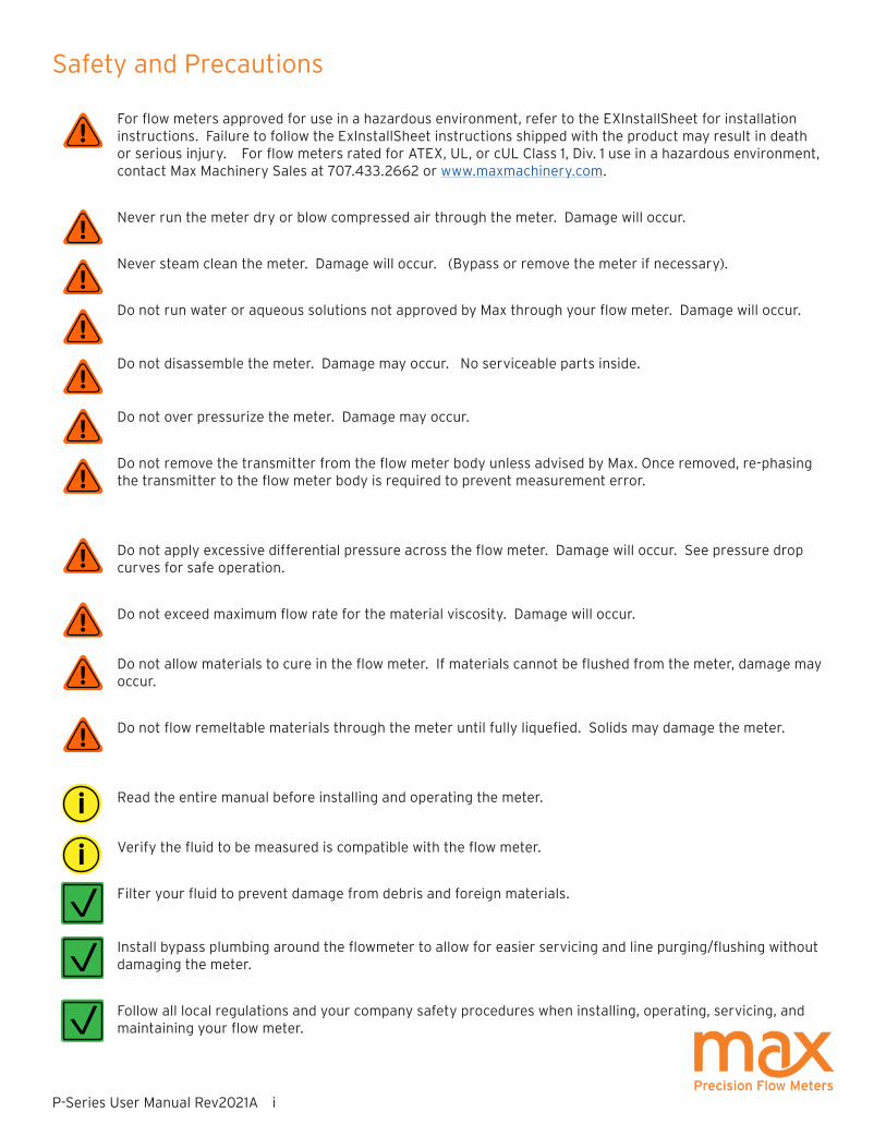
For flow meters approved for use in a hazardous environment, refer to the EXInstallSheet for installation instructions. Failure to follow the ExInstallSheet instructions shipped with the product may result in death or serious injury. For flow meters rated for ATEX, UL, or cUL Class 1, Div. 1 use in a hazardous environment, contact Max Machinery Sales at 707.433.2662 or www.maxmachinery.com.
Never run the meter dry or blow compressed air through the meter. Damage will occur.
Never steam clean the meter. Damage will occur. (Bypass or remove the meter if necessary).
Do not run water or aqueous solutions not approved by Max through your flow meter. Damage will occur.
Do not disassemble the meter. Damage may occur. No serviceable parts inside.
Do not over pressurize the meter. Damage may occur.
Do not remove the transmitter from the flow meter body unless advised by Max. Once removed, re-phasing the transmitter to the flow meter body is required to prevent measurement error.
Do not apply excessive differential pressure across the flow meter. Damage will occur. See pressure drop curves for safe operation.
Do not exceed maximum flow rate for the material viscosity. Damage will occur.
Do not allow materials to cure in the flow meter. If materials cannot be flushed from the meter, damage may occur.
Do not flow remeltable materials through the meter until fully liquefied. Solids may damage the meter.
Read the entire manual before installing and operating the meter.
Verify the fluid to be measured is compatible with the flow meter.
Filter your fluid to prevent damage from debris and foreign materials.
Install bypass plumbing around the flowmeter to allow for easier servicing and line purging/flushing without damaging the meter.
Follow all local regulations and your company safety procedures when installing, operating, servicing, and maintaining your flow meter.
Safety and Precautions
!
!
!
!
!
!
!
!
!
!
!
i
i

P-Series User Manual Rev2021A ii
Max Machinery, Inc. (MMI) reserves the right to change product specifications without notice to improve performance, reliability, or manufacturability. MMI shall not be held liable for operational, technical, or editorial errors/omissions. Visit our web site for the latest version of this user manual.
Max Machinery, Inc., 33A Healdsburg Avenue, Healdsburg, CA 95448 USA
707.433.2662 | www.maxmachinery.com
Table of Contents
Safety and Precautions ........................................................................ i
Table of Contents .................................................................................. ii
How It Works ........................................................................................... 1
Installation Mechanical ........................................................................ 2
Mechanical Operation ..........................................................................4
Installation Electrical ............................................................................5
Electrical Quick Start ...........................................................................6
Field Compensation of Transmitter .................................................10
LED Functions .......................................................................................12
Specifications ........................................................................................13
Dimensions ............................................................................................19
Charts ....................................................................................................29
Part Matrix ............................................................................................ 31
Available Accessories .........................................................................34
Troubleshooting and Service Request ...........................................35
Additional Information Available .....................................................35

P-Series User Manual Rev2021A 1
How It WorksMax P-Series Precision Flow Meters are positive displacement piston meters that are able to operate over a wide range of flow rates and fluid viscosities. High accuracy measurement is achieved through precision machined radial pistons that move proportional to the flow. High resolution outputs are produced by measuring the direction and speed of the pistons and converting the signals to analog or frequency outputs. Flows can be monitored from 0.005 cc/min up to 35 liters/min with fluid temperatures from -40°C to 225°C and pressure ratings of 250 psi (17 bar), 3000 psi (210 bar), and 7250 psi (500 bar) depending upon the model. The industrial meter electronics are protected against water, dust, and most corrosive liquids. The 5-pin Turck connector provided is IP68. Additionally, IP66 rated explosion proof enclosures, combined with a choice of one-part and two-part, high temperature designs with remote electronics cover a wide range of application environments – from the laboratory to harsh industrial processes. Optional seal materials allow for different fluid compatibility.
Max Machinery, Inc. designs, manufactures, calibrates, and refurbishes high accuracy, high resolution, precision liquid flow meters under an ISO 9001:2015 certified quality management system. All Max Precision Flow Meters are tested and calibrated in our lab and provide measurements traceable to NIST. If your calibration certificate is lost or missing, contact MMI with your meter serial number for a copy.

P-Series User Manual Rev2021A 2
Your Max Flow Meter has been configured at the factory to be used out of the box based on your submitted application data. Plumb it, wire it, and use it. The following section will provide instructions on how to properly plumb your Max Flow Meter in the liquid lines of your application.
Use the “IN” port or follow the flow direction arrow markings for the primary flow direction. Install the meter on the discharge side of the pump whenever possible. Excessive vibration at the meter should be avoided.
Orientation: Preferred mounting orientation of the meter depends on meter type. The orientation optimizes air purging and/or minimizes heat transfer to the electronics. P-Series meters with in line ports prefereably mount with the transmitter facing down or alternately on the side. P001 and P002 with offset ports mount with the transmitter facing up. These mounting orientations prevent air in the system that can cause response delays and errors in measurement.
NPT fittings: Always use pipe sealant or pipe tape to install fittings, and leave the first thread of pipe exposed. Ensure the tape or sealant does not accidentally enter the meter.
SAE / BSPP fittings: Always use process fluid compatible lubricant on the o-ring to attach the fitting to the meter.
Compression Fittings: P001 compression fittings are based on Swagelok style ferrules (see fig. 1). Do not use other manufacturer’s parts because the sealing angle may not be the same. Fitting kits contain detailed instructions and are shipped with every meter (contact Max Machinery for spare ferrule kits). Always torque to values on fitting kit instructions. Select tubing grades that meet or exceed your system pressure requirements. If using flexible tubing, install a tubing insert to allow compression ferrules to seal (suggested inserts: Swagelok SS-405-2, SS-405-03 or SS-405-170). To reuse a tube fitting, mark the nut and meter before removal. When re-installing, tighten to align the marks then tighten a quarter turn farther.
Installation - Mechanical
P001
FLOW
FLOWP213
Ferrule
Meter body
Lock ringNut Fluid line
Figure 2. Compression Fitting
FLOWP213

P-Series User Manual Rev2021A 3
Bypass Valves: Install valves to allow system start-up, filter replacement, or flow meter removal without completely shutting the system down and draining the lines. See diagram.
Failure to use a bypass at start up may lead to flow meter damage due to debris, overspeeding the meter with air in the lines, and pressure shock due to initial line surges.
Filtration: A 5 micron filter is recommended on the inlet for the P001 flow meter. A 10 micron filter is recommended on the inlet for all other P-Series flow meters. If measuring bi-directional flow, a filter should be installed on both sides of the flow meter. Materials with fibrous or non-abrasive particulate matter may need to be run without filters.
Clean Plumbing: Before installing the flow meter, the system lines shall be cleaned and free of all debris or manufacturing particulates. Purging lines with compressed air or steam are typical cleaning methods. Do not use compressed air or steam on the Max flow meter, damage will occur.
High Temperatures: Orient your meter so the transmitter is to the side or below to minimize heat transfer by convection from the flow meter to the transmitter. The transmitter is the most heat sensitive element in the system. Consult the chart on page 8 for specific limits on fluid and ambient maximum temperatures. When operating in the upper temperature ranges, always insulate the meter but leave the transmitter housing exposed so it radiates heat. An optional heater block can be used on the flow meter to keep it at the fluid operating temperature. For substances solid at room temperature, a heater block may be required to keep material molten to flow through the meter.
Installation - Mechanical
FLOW
INSULATION HERE
RADIATE HEAT HERE

P-Series User Manual Rev2021A 4
Mechanical - Operation
Determine that the following parameters of your flow metering system are within the specifications for the specific meter being used:
Maximum System Pressure (Specifications) Differential Pressure across meter (Pressure Drop Curves) Maximum Flow Rate (Pressure Drop Curves) Metered Fluid Temperature (Sales specification, transmitter specifications page 8)
If the metered fluid is greater than 28°C (80°F) over ambient, see the “High Temperature Start Up” section below.
With valves (#1) and (#2) closed, slowly open valve (#3) (bypass) to clear the lines of foreign particles and air.Slowly open the inlet valve (#1). Slowly open the outlet valve (#2). Completely close the bypass valve.
No routine maintenance, cleaning, or lubrication of the flow meter is required. A routine filter cleaning schedule should be established. The system should be shut down if abnormal noises occur or if unusual differential pressures across the meter are encountered.
High Temperature Start Up: For fluids above 82°C (150°F) based on 21°C (70°F) ambient, a special procedure is required to prevent thermal shock and permanent damage to the flow meter. The warm up time is determined by the equation below:
TIME (minutes) = connector size (inches) x (operating temperature (°F)-125) 10
— OR — TIME (minutes) = connector size (inches) x (operating temperature (°C)-52) 10
Valves (#1) and (#2) must be closed. Open the bypass valve (#3) in gradual steps until the bypass piping is stabilized at operating temperature. Open valve (#1) slightly and allow the temperature to stabilize around the flow meter. Valve (#1) can then be opened completely.
Open valve (#2) slightly. The flow meter may make unusual noises or bind at this point. Leave the valve at this setting until normal meter operation occurs, at which point valve (#2) can be gradually opened all the way. Slowly close the bypass valve (#3).

P-Series User Manual Rev2021A 5
Max P-Series Precision Flow Meters transmitters come from the factory pre-assembled to the mechanical metering component and configured to be used out of the box based on your submitted application data. Plumb it, wire it, and use it. The following section describes how to properly wire your Max Flow Meter into your application electronics.
There are various combinations of transmitter components and outputs. These options include:
- Industrial or Hazardous Location Transmitter Housing
- Frequency or Analog Output Signal
- Uni-directional or Bi-directional Output Signal
- Standard, High Temperature, and Ultra High Temperature Housings
To determine what transmitter type you have, refer to the Max Part Number matrices on pages 31-33 and decode your flow meter part number.
Installation - Electrical
WARNING: Refer to the EXInstall Sheet for proper installation in hazardous locations.!
WARNING: Electrical shock hazard. Serious or fatal injury may occur. Installation/Removal should only be completed by trained and authorized personnel.
!
!CAUTION: Verify transmitter output type (Analog or Frequency) before wiring. Inappropriate wiring could result in damaging the circuit.
CAUTION: Before opening/accessing the electronics lid, make sure the top of the meter and surrounding components are dry and no moisture or fluids can contact the electrical components. Non-warranty damage may occur.
!

P-Series User Manual Rev2021A 6
Quick Start - No adjustments to factory settingsYour Max Flow Meter is connected to your process automation electronics via a 5-pin M12 Turck connector if an industrial transmitter or via a 5-pin connector within a hazardous location housing with a 1/2 inch conduit connection. Please refer to the EXInstall Sheet for proper installation of the wiring to the hazardous location housing.
Wire the 5-pin Turck cable to your process automation equipment in accordance with the diagrams below depending upon which transmitter type you purchased. Then connect the Turck cable to the Turck fitting on the Max Flow Meter.
Set your ouput reading on your process automation electronics to match the calibration sheet supplied with your flow meter.
You are ready to measure your liquid flow application.
Start-up Instructions - Adjustments to Factory Settings RequiredIf you need to make adjustments to your Max Flow Meter prior to use, you will need to purchase and use the Max Machinery Interface Software Kit (SFT-KIT-001). This will allow you to change the flow meter output signal frequency or analog range to meet your application equipment needs.
To access the port on the circuit board, unscrew the transmitter lid by hand. The transmitter lid has four thread paths. When reinstalling the lid, the cable may be misaligned. To realign the cable, remove the lid and rotate up to 180° and retighten using an alternate starting point. Tighten to compress the O-ring seal.
Max Flow Meters do not come with a visual interface, they must be connected to an electronic display, PLC/DAC/counter card or other process automation electronics to collect the data and display a visual reading.
You must determine if your process automation electronics have the capability to accept the high frequency output of the Max Flow Meter. If your system cannot accept the data at the pre-set frequency, then use the Max Machinery Interface Software Kit to adjust the frequency output to a lower setting that matches your system.
Refer to the Max Machinery Interface Software Kit Manual for instructions on how to change the flow meter output signal frequency or analog range to meet your application’s equipment needs.
Installation - Electrical

P-Series User Manual Rev2021A 7
Applies only to transmitters with 5-pin, M12 style connectors. For hazardous location transmitters with 1/2 inch conduit connections, please refer to the EXInstall sheet.
A current sinking device uses the transmitter’s transistor output to act as a switch. Positive DC voltage must be applied to the transmitter's output pin (#2). When the pulse output is triggered, this voltage is grounded to zero volts by the transmitter. Warning: Use a 5k ohm resistor to limit current if your system does not have other means to limit current into the transmitter.
PLC
Digital
Input
V+
V+
Out0V
Transmitter
Turck Pin #2 on
Industrial housings
Terminal 3 on ATEX
rated housings
Current Sinking Wiring (PN ending S/-)
Electrical Installation Instructions - 5-pin Turck Connectors
Turck® Connector
PCA Label
Pin #Mating CableWire Color
Power * V+ 1 Brown
Common Com 4 Black
Signal Output (+) Sig 5 Grey
Signal Output (—)** Ret 2 White
Case Ground Case 3 Blue
21
4
5
3
Analog Current or Voltage Output Transmitters (PN ending A/-, B/-, C/-, or D/-)
* Analog transmitters with part numbers ending in A/- or C/- are 24Vdc power. Part numbers ending in B/- or D/- are 12Vdc power.
** To minimize signal noise, analog output transmitters are fully isolated. If your PLC does not ground the negative signal input, there is a risk of a ground shift that could drive the signal out of the range of detection. To prevent this from occuring, install a 10k pull down resistor between Common and Signal Output (-).
Turck® Connector
PCA Label
Pin #Mating Cable Wire Color
Power (+5 to 26 Vdc) V+ 1 Brown
Common Com 4 Black
Pulse Output Ph A 2 White
Output Phase B (Quad only) Ph B 5 Grey
Case Ground Case 3 Blue
21
4
5
3
Frequency Output Transmitters (PN ending N/-)

P-Series User Manual Rev2021A 8
Electrical - Operating Information
Max Flow Meters require a fully isolated power supply to operate. Refer to the Max Machinery Interface Software Kit Manual for instructions on how to change the flow meter output signal frequency or analog range to meet your application’s equipment needs.
Transmitters should not be removed from the flow meter for any field servcing or adjustments. PCA replacement kits do not require the removal of the transmitter housing. The flow meter and transmitter must be shipped back to the factory for calibration or service as the complete serialized unit.
Removal note: If an industrial transmitter needs to be removed from the flow meter for installation, be sure to retighten the transmitter snugly in order to ensure proper sensor alignment. To remove, disconnect the Turck cable and unscrew the industrial transmitter. Use a wrench if necessary. To reattach the industrial transmitter, hand tighten only (~3 ft-lb). For hazardous location transmitters, refer to the EXInstall Sheet for proper installation.
Moisture Seal Protection: On all models, the housing is designed as a liquid and vapor-tight enclosure. There are O—ring seals at the lid and also the base of the housing in some models; these need to be fully seated. A properly sealed transmitter will prevent the formation of damaging moisture inside the housing. Industrial transmitters have Turck connectors sealed to the lid at the factory and are ready for use. There are no adjustments or servicing that require the connector to be removed from the transmitter lid. Hazardous location transmitters have an NPT connection. Refer to the EXInstall Sheet for proper installation.
Environmental: The Industrial transmitters are rated to operate in the following fluid temperature ranges at ambient temperature ranges of -40°C to 80°C Standard and 110°C High and Ultra High Temperature Housings. With ambient temperature increases, the maximum fluid temperature at the flow meter is de-rated as shown in the charts below. Hazardous location transmitters have different ambient and fluid temperature ratings, refer to the EXInstall Sheet for proper installation.
Industrial Transmitter Temperature Ratings
-25
0
50
20
40
60
80
100
120
100 150 200 250 300
Process Temperature °C
Am
bie
nt
Tem
per
atu
re °
C
225
110
Ultra High temperature
2 part pickup
Standard High temperature
2 part pickup
Model P001 and P002 (only)

P-Series User Manual Rev2021A 9
LED Rotation/Output IndicatorsAll Max transmitters incorporate an alternating red/green or blue/green LED to indicate magnet rotation in the meter. The color changes each 1/2 revolution of the meter. Additionally, when no flow signal is present, a rapidly flashing red light indicates the following errors:
Frequency (PN ending N/- or S/-): Flashes 8x per second indicate magnet is not detected
Analog (PN ending A/-, B/-, C/-, D/-): Flashes 2x per second indicate excessive temperature Flashes 8x per second indicate magnet is not detected Flashes 16x per second indicate a wiring fault in the output circuit
Note: There are no selections or adjustments on the circuit board. Setting changes are made through the Interface Software Kit (SFT-KIT-001), sold separately. If the PCA is not functioning, PCA replacement kits are available by contacting Max Machinery.
High Temperature Instructions
Troubleshooting
Orient your meter so the transmitter is to the side or below to minimize heat transfer by convection from the flow meter to the transmitter. The transmitter is the most heat sensitive element in the system. Consult your user manual for specific limits on fluid and ambient maximum temperatures. When operating in the upper temperature ranges, always insulate the meter but leave the transmitter housing exposed so it radiates heat. An optional heater block can be used on the flow meter to keep it at the fluid operating temperature. For substances solid at room temperature, a heater block may be required to keep material molten to flow through the meter.
FLOW
FLOW
INSULATION HERE
RADIATE HEAT HERE

P-Series User Manual Rev2021A 10
Field Compensation of TransmitterThe transmitter LED on the circuit board indicates a functioning system when it is producing a pulse output or detecting
magnet travel in the meter.
An alternating blue/green LED indicates that the circuit is detecting a magnet and provides an output signal.
A steady or flashing red LED indicates a problem with the transmitter PCA. Contact Max Machinery to have your flow
meter refurbished.
The Compensation Algorithm adjusts for variations in Hall sensor and flow meter characteristics to provide a stable, undamped output frequency that accurately represents the instantaneous flow rate. This feature is factory set when the meter is assembled. If the transmitter PCA is replaced or reset, the compensation can be performed via the gold PCA button or through the software kit.
The only method of altering additional factory set parameters of the meter is through the Interface Software Kit, part number SFT-KIT-001. Pulse Output Scaling, Analog Output Limits and Scaling, Signal Filtering Options and Compensation settings are the adjustable variables.
CAUTION: Before opening/accessing the electronics lid, make sure the top of the P234 meter and surrounding components are dry and no moisture or fluids can contact the electrical components. Non-warranty damage may occur.
!
WARNING: Electrical shock hazard. Serious or fatal injury may occur. Access should only be completed by trained and authorized personnel.!
Instructions to access the gold PCA button and software serial port:
- Unscrew the electronics lid with a quarter turn.
- Carefully move aside the lid with o-ring seal. The M12 connector on the lid remains attached with wires.
- Optional: follow instructions for SFT-KIT-001 to connect to software serial port.
- Follow field compensation instructions on page 11.
- When reinstalling the lid, the cable may be misaligned. To realign the cable, remove the lid and rotate up to 180° and retighten using an alternate starting point. Tighten to compress the O-ring seal.
Software Serial Port
Gold PCA Button
LED

P-Series User Manual Rev2021A 11
Field Compensation of Transmitter Continued
When a transmitter PCA is replaced or reset in the field, the compensation routine should be performed to optimize the performance of the system. This routine requires a steady flow rate for the flow meter model as shown in Table A below. The flow meter being compensated must not be used for system flow rate feedback control during this process. The transmitter output is disabled during the compensation routine.
If you are unable to run a stable flow in the field, send your meter in to Max Machinery for calibration.
The compensation routine is as follows:
1. Place your system in ‘manual’ mode or run in ‘open loop’ mode with no flow meter feedback control. Max transmitter output shuts off during field compensation routine. Loss of signal to ‘closed loop control’ modes can affect the flow stabilization of the system and the compensation of the Max meter.
2. Stabilize the flow rate for your flow meter model as shown in Table A below.
3. Activate the compensation routine:
A - When using the software via the serial port connection, select ‘field compensation’ in the software.
OR
B - If NOT using software, push the Gold PCA Button using a non-conductive tool.
4. The blue/green LED will change to solid blue for 5 revolutions of the meter. See table LED Functions on next page for duration of compensation process. Duration is dependent upon flow rate and requires at least 10 seconds at maximum flow and 90 seconds at minimum flow.
5. A green LED light indicates a successful update of the compensation, a red LED light indicates the new compensation failed. Additional information is available through the interface software.
6. Return your system to ‘operating’ mode or restore settings to allow for feedback control.
Max Flow Meter Minimum Flow Rate (cc/min) Maximum Flow Rate (cc/min)
P001 1.2 200
P213 3.4 1210
P002 3.5 1250
P214 40 10,000
P215 180 35,000
Field Compensation Flow Rate Table A

P-Series User Manual Rev2021A 12
LED Functions
Normal OperationSTATUS LED ACTIONFunctioning - System Not Flowing Blue or Green Steady Meter is functioning, but no flow is detected in
the system.
Functioning - System Flowing Blue / Green alternating colors
Meter is functioning, flow is occuring in the system. Note: At high flow rates the alternating Blue/Green flashes may appear as a single steady color.
Meter Malfunction Red Steady Refurbish Meter.
No Power / Meter Failure No Light - Verify power supply to meter.
- Verify wiring follows diagrams on page 4.
- If power and wiring are verified, refurbish meter.
Compensation via Interface Software Kit or Gold PCA ButtonSTATUS LED ACTIONCompensate button pushed/clicked Blue Steady - Steady light for 4-5 revolutions of meter.
Compensation Succeeded Green Steady - Steady light for 5 seconds.
- Software will show “Success” on screen.
Compensation Failed Red Steady - Steady light for 5 seconds.
- Software will show “Flow too low/ too high/ unstable” on screen.
Note: Revolutions of meter are dependent on expected fluid flow rate. Per Table A, the maximum compensation flow rate will take approximately 10 seconds and the minimum compensation flow rate will take approximately 90 seconds to complete 5 revolutions at the stated flow rates.
If compensation fails, restart the compensation process. When using the Interface Software Kit, follow instructions provided to correct errors prior to attempting compensation again. If problems persist, contact Max Machinery at 707-433-2662 or at www.maxmachinery.com.

P-Series User Manual Rev2021A 13
Specifications
P001LA SPECIFICATIONS Flow Range 0.005 to 200 cc/min Accuracy (3 cP) ± 0.2% of reading over a 200:1 rangeMaximum Operating Pressure 250 psi (17 bar) Weight 0.4 kg Recommended Filtration 5 micronPort Size(s) 1/4 inch or 6 mm tube fittingFluids Most non-aqueous, hydrocarbon based fluids
MATERIALS OF CONSTRUCTIONExternal Aluminum, Hard Anodized, type 6061
Wetted Hard Anodized Aluminum, type 6061; Stainless steel, type 316, 440C, 17-4; Silicon Nitride; Nickel Based CarbideO-Rings Standard: Viton® Optional: Perfluoroelastmer
FREQUENCY TRANSMITTER
Output Signal Standard: 5 Vdc, single phase Optional: Quadrature 5 Vdc, two phase Current sinking, 20 mA max., single phaseK-Factor Single Phase: 12,000 pulses/cc
Two Phase: 24,000 pulses/cc, 4x decoded (6,000 pulses/cc/phase, 1x decoded) Power Supply Requirements 5-26 Vdc @ 30ma Ambient Operational Range -40°C to 80°C
Metered Liquid Temp Range -40°C to 90°C
(based on 20° ambient)
ANALOG TRANSMITTEROutput Signal Any range of ± 10V or ± 20mA linearized and damped with anti-dither protection
Power Supply Requirements 12Vdc @ 90 mA, 24Vdc @ 45 mA
Ambient Operational Range -40°C to 80°CMetered Liquid Temp Range -40°C to 90°C
(based on 20° ambient)

P-Series User Manual Rev2021A 14
Specifications
P001 SPECIFICATIONS Flow Range 0.005 to 200 cc/min Accuracy (3 cP) ± 0.2% of reading over a 200:1 rangeMaximum Operating Pressure 7250 psi (500 bar) Weight 1.1 kg Recommended Filtration 5 micronPort Size(s) 1/4 inch or 6 mm tube fittingFluids Most non-aqueous, hydrocarbon based fluids
MATERIALS OF CONSTRUCTIONExternal Stainless steel, type 316
Wetted Stainless steel, type 316, 440C; Silicon Nitride; Nickel Based CarbideO-Rings Standard: Viton® Optional: Perfluoroelastmer
FREQUENCY TRANSMITTER
Output Signal Standard: 5 Vdc, single phase Optional: Quadrature 5 Vdc, two phase Current sinking, 20 mA max., single phaseK-Factor Single Phase: 12,000 pulses/cc
Two Phase: 24,000 pulses/cc, 4x decoded (6,000 pulses/cc/phase, 1x decoded) Power Supply Requirements 5-26 Vdc @ 30ma
Ambient Operational Range -40°C to 80°C, Single piece - Two piece to 110°C
Metered Liquid Temp Range -40°C to 90°C, Standard model(based on 20° ambient) -40°C to 155°C, Two piece, high temperature model -40°C to 225°C, Two piece, ultra high temperature model
Compliance CE Certified, Ex-proof version available with ATEX/IECEx II 2 G Ex db IIB Tx Gb as well as UL, cUL certification for Class 1, Division 1, Groups C and D, Tx
ANALOG TRANSMITTEROutput Signal Any range of ± 10V or ± 20mA linearized and damped with anti-dither protection
Power Supply Requirements 12Vdc @ 90 mA, 24Vdc @ 45 mA
Ambient Operational Range -40°C to 80°C, Single piece - Two piece to 110°C
Metered Liquid Temp Range -40°C to 90°C, Standard model(based on 20° ambient) -40°C to 155°C, Two piece, high temperature model -40°C to 225°C, Two piece, ultra high temperature model
Compliance CE Certified, Ex-proof version available with ATEX/IECEx II 2 G Ex db IIB Tx Gb as well as UL, cUL certification for Class 1, Division 1,
Groups C and D, Tx
P-Series User Manual Rev2021A 15
Specifications
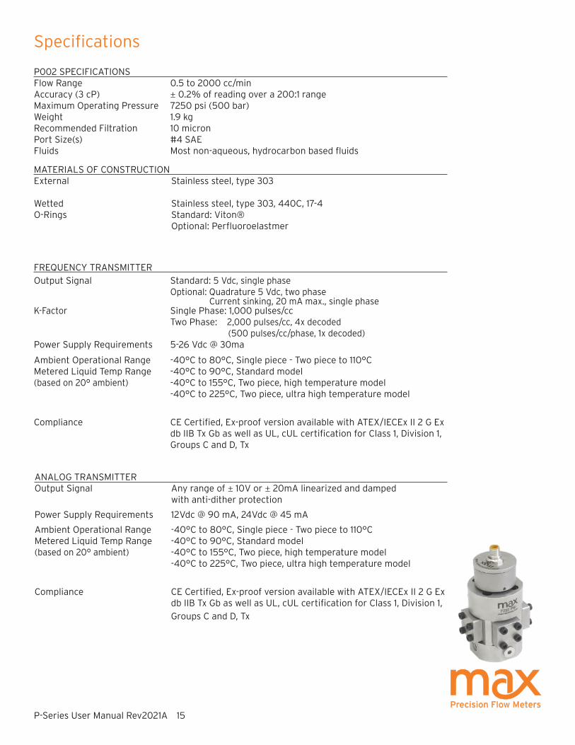
P002 SPECIFICATIONS Flow Range 0.5 to 2000 cc/min Accuracy (3 cP) ± 0.2% of reading over a 200:1 rangeMaximum Operating Pressure 7250 psi (500 bar) Weight 1.9 kg Recommended Filtration 10 micronPort Size(s) #4 SAEFluids Most non-aqueous, hydrocarbon based fluids
MATERIALS OF CONSTRUCTIONExternal Stainless steel, type 303
Wetted Stainless steel, type 303, 440C, 17-4O-Rings Standard: Viton® Optional: Perfluoroelastmer
FREQUENCY TRANSMITTER
Output Signal Standard: 5 Vdc, single phase Optional: Quadrature 5 Vdc, two phase Current sinking, 20 mA max., single phaseK-Factor Single Phase: 1,000 pulses/cc
Two Phase: 2,000 pulses/cc, 4x decoded (500 pulses/cc/phase, 1x decoded) Power Supply Requirements 5-26 Vdc @ 30ma
Ambient Operational Range -40°C to 80°C, Single piece - Two piece to 110°C
Metered Liquid Temp Range -40°C to 90°C, Standard model(based on 20° ambient) -40°C to 155°C, Two piece, high temperature model -40°C to 225°C, Two piece, ultra high temperature model
Compliance CE Certified, Ex-proof version available with ATEX/IECEx II 2 G Ex db IIB Tx Gb as well as UL, cUL certification for Class 1, Division 1, Groups C and D, Tx
ANALOG TRANSMITTEROutput Signal Any range of ± 10V or ± 20mA linearized and damped with anti-dither protection
Power Supply Requirements 12Vdc @ 90 mA, 24Vdc @ 45 mA
Ambient Operational Range -40°C to 80°C, Single piece - Two piece to 110°C
Metered Liquid Temp Range -40°C to 90°C, Standard model(based on 20° ambient) -40°C to 155°C, Two piece, high temperature model -40°C to 225°C, Two piece, ultra high temperature model
Compliance CE Certified, Ex-proof version available with ATEX/IECEx II 2 G Ex db IIB Tx Gb as well as UL, cUL certification for Class 1, Division 1,
Groups C and D, Tx

P-Series User Manual Rev2021A 16
Specifications
P213 SPECIFICATIONS Flow Range 0.5 to 1800 cc/min Accuracy (3 cP) ± 0.2% of reading over a 200:1 rangeMaximum Operating Pressure 3000 psi (210 bar) Weight 1.0 kg Recommended Filtration 10 micronPort Size(s) 1/8 inch NPT, #4 SAE, or manifold mountFluids Most non-aqueous, hydrocarbon based fluids
MATERIALS OF CONSTRUCTIONExternal Stainless steel, type 303
Wetted Stainless steel, type 303, 440C, 17-4O-Rings Standard: Viton® Optional: Teflon®, Perfluoroelastmer, Neoprene
FREQUENCY TRANSMITTER
Output Signal Standard: 5 Vdc, single phase Optional: Quadrature 5 Vdc, two phase Current sinking, 20 mA max., single phaseK-Factor Single Phase: 1,000 pulses/cc
Two Phase: 2,000 pulses/cc, 4x decoded (500 pulses/cc/phase, 1x decoded) Power Supply Requirements 5-26 Vdc @ 30ma
Ambient Operational Range -40°C to 80°C, Single piece - Two piece to 110°C
Metered Liquid Temp Range -40°C to 90°C, Standard model(based on 20° ambient) -40°C to 225°C, Two piece, ultra high temperature model
Compliance CE Certified, Ex-proof version available with ATEX/IECEx II 2 G Ex db IIB Tx Gb as well as UL, cUL certification for Class 1, Division 1, Groups C and D, Tx
ANALOG TRANSMITTEROutput Signal Any range of ± 10V or ± 20mA linearized and damped with anti-dither protection
Power Supply Requirements 12Vdc @ 90 mA, 24Vdc @ 45 mA
Ambient Operational Range -40°C to 80°C, Single piece - Two piece to 110°C
Metered Liquid Temp Range -40°C to 90°C, Standard model(based on 20° ambient) -40°C to 225°C, Two piece, ultra high temperature model
Compliance CE Certified, Ex-proof version available with ATEX/IECEx II 2 G Ex db IIB Tx Gb as well as UL, cUL certification for Class 1, Division 1,
Groups C and D, Tx

P-Series User Manual Rev2021A 17
Specifications
P214 SPECIFICATIONS Flow Range 5 to 10,000 cc/min Accuracy (3 cP) ± 0.2% of reading over a 200:1 rangeMaximum Operating Pressure 3000 psi (210 bar) Weight 3.8 kg Recommended Filtration 10 micronPort Size(s) 3/8 inch NPT, #6 SAE, or manifold mountFluids Most non-aqueous, hydrocarbon based fluids
MATERIALS OF CONSTRUCTIONExternal Stainless steel, type 303
Wetted Stainless steel, type 303, 440C; Cobalt based carbideO-Rings Standard: Viton® Optional: Teflon®, Perfluoroelastmer, Neoprene
FREQUENCY TRANSMITTER
Output Signal Standard: 5 Vdc, single phase Optional: Quadrature 5 Vdc, two phase Current sinking, 20 mA max., single phaseK-Factor Single Phase: 90 pulses/cc
Two Phase: 180 pulses/cc, 4x decoded (45 pulses/cc/phase, 1x decoded) Power Supply Requirements 5-26 Vdc @ 30ma
Ambient Operational Range -40°C to 80°C, Single piece - Two piece to 110°C
Metered Liquid Temp Range -40°C to 90°C, Standard model(based on 20° ambient) -40°C to 225°C, Two piece, ultra high temperature model
Compliance CE Certified, Ex-proof version available with ATEX/IECEx II 2 G Ex db IIB Tx Gb as well as UL, cUL certification for Class 1, Division 1, Groups C and D, Tx
ANALOG TRANSMITTEROutput Signal Any range of ± 10V or ± 20mA linearized and damped with anti-dither protection
Power Supply Requirements 12Vdc @ 90 mA, 24Vdc @ 45 mA
Ambient Operational Range -40°C to 80°C, Single piece - Two piece to 110°C
Metered Liquid Temp Range -40°C to 90°C, Standard model(based on 20° ambient) -40°C to 225°C, Two piece, ultra high temperature model
Compliance CE Certified, Ex-proof version available with ATEX/IECEx II 2 G Ex db IIB Tx Gb as well as UL, cUL certification for Class 1, Division 1,
Groups C and D, Tx

P-Series User Manual Rev2021A 18
Specifications
P215 SPECIFICATIONS Flow Range 25 cc/min to 35 liters/min Accuracy (3 cP) ± 0.2% of reading over a 200:1 rangeMaximum Operating Pressure 3000 psi (210 bar) Weight 10.4 kg Recommended Filtration 10 micronPort Size(s) 1/2 inch NPT or #8 SAEFluids Most non-aqueous, hydrocarbon based fluids
MATERIALS OF CONSTRUCTIONExternal Stainless steel, type 303
Wetted Stainless steel, type 303, 440C, 17-4O-Rings Standard: Viton® Optional: Teflon®, Perfluoroelastmer, Neoprene
FREQUENCY TRANSMITTER
Output Signal Standard: 5 Vdc, single phase Optional: Quadrature 5 Vdc, two phase Current sinking, 20 mA max., single phaseK-Factor Single Phase: 20,000 pulses/L
Two Phase: 40,000 pulses/L, 4x decoded (10,000 pulses/L/phase, 1x decoded) Power Supply Requirements 5-26 Vdc @ 30ma
Ambient Operational Range -40°C to 80°C, Single piece - Two piece to 110°C
Metered Liquid Temp Range -40°C to 90°C, Standard model(based on 20° ambient) -40°C to 225°C, Two piece, ultra high temperature model
Compliance CE Certified, Ex-proof version available with ATEX/IECEx II 2 G Ex db IIB Tx Gb as well as UL, cUL certification for Class 1, Division 1, Groups C and D, Tx
ANALOG TRANSMITTEROutput Signal Any range of ± 10V or ± 20mA linearized and damped with anti-dither protection
Power Supply Requirements 12Vdc @ 90 mA, 24Vdc @ 45 mA
Ambient Operational Range -40°C to 80°C, Single piece - Two piece to 110°C
Metered Liquid Temp Range -40°C to 90°C, Standard model(based on 20° ambient) -40°C to 225°C, Two piece, ultra high temperature model
Compliance CE Certified, Ex-proof version available with ATEX/IECEx II 2 G Ex db IIB Tx Gb as well as UL, cUL certification for Class 1, Division 1,
Groups C and D, Tx


P-Series User Manual Rev2021A 21
Dimensions
P002 SPECIFICATIONS
BOTTOM VIEW
MODEL P002 WITH SAE PORT AND INDUSTRIAL HOUSING
MODEL P002 WITH SAE PORT AND EX-PROOF HOUSING
EX-PROOF HOUSING
TOP VIEW

P-Series User Manual Rev2021A 22
Dimensions
P213 SPECIFICATIONS
EX-PROOF HOUSING
TOP VIEW
MODEL P213 WITH NPT PORT
AND INDUSTRIAL HOUSING
BOTTOM VIEW
MODEL P213 WITH NPT PORT AND EX-PROOF HOUSING

P-Series User Manual Rev2021A 23
Dimensions
P213 SPECIFICATIONS
EX-PROOF HOUSING
TOP VIEW
BOTTOM VIEW
MODEL P213 WITH SAE PORT AND EX-PROOF HOUSING
MODEL P213 WITH SAE PORT
AND INDUSTRIAL HOUSING

P-Series User Manual Rev2021A 24
Dimensions
P213 SPECIFICATIONS
BOTTOM VIEW MODEL P213 WITH MANIFOLD PORT AND EX-PROOF HOUSING
MODEL P213 WITH MANIFOLD PORT AND INDUSTRIAL HOUSING
EX-PROOF HOUSING
TOP VIEW
P-Series User Manual Rev2021A 25
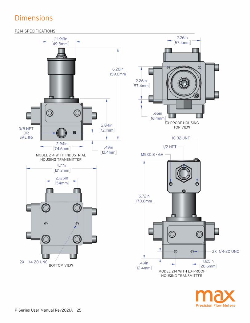
Dimensions
P214 SPECIFICATIONS
MODEL 214 WITH INDUSTRIAL HOUSING TRANSMITTER
BOTTOM VIEW
EX-PROOF HOUSING
TOP VIEW
MODEL 214 WITH EX-PROOF HOUSING TRANSMITTER

P-Series User Manual Rev2021A 26
Dimensions
P214 SPECIFICATIONS
EX-PROOF HOUSING
TOP VIEW
MODEL 214 WITH EX-PROOF HOUSING TRANSMITTER
BOTTOM VIEW
MODEL 214 WITH INDUSTRIAL HOUSING TRANSMITTER
P-Series User Manual Rev2021A 27
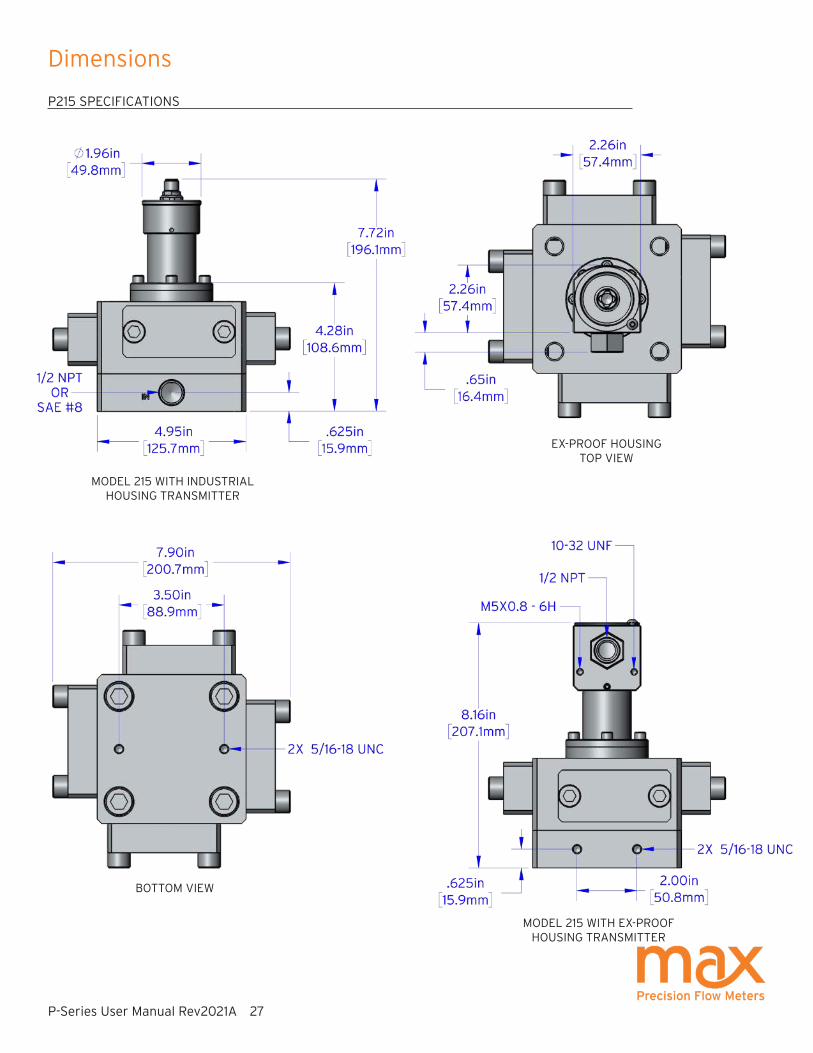
Dimensions
P215 SPECIFICATIONS
BOTTOM VIEW
MODEL 215 WITH INDUSTRIAL HOUSING TRANSMITTER
EX-PROOF HOUSING
TOP VIEW
MODEL 215 WITH EX-PROOF HOUSING TRANSMITTER

P-Series User Manual Rev2021A 28
Dimensions
REMOTE PCA ENCLOSURE SPECIFICATIONS
REMOTE PCA ENCLOSURE FOR HIGH TEMPERATURE TRANSMITTERS
(Not Shown: Industrial 2 meter interconnect cable included, Ex-Proof user supplied interconnect cable required)

P-Series User Manual Rev2021A 29
Charts
P001LA Pressure Drop Graph
P001 Pressure Drop Graph
P002 Pressure Drop Graph

P-Series User Manual Rev2021A 30
Charts
P213 Pressure Drop Graph
P214 Pressure Drop Graph
P215 Pressure Drop Graph

P-Series User Manual Rev2021A 31
an ISO 9001:2015 certified company
Max Machinery, Inc.
33A Healdsburg Avenue
Healdsburg, CA 95448
maxmachinery.com
T + 1 707.433.2662 ©2008-2021
Positive Displacement Flow MetersPiston Type, P-Series 250 psi (17 bar) rated
Product includes single directional calibration, bi-directional calibrations for Analog and Quadrature devices are optional.
Flow Meter Selections Transmitter Selections
Model # LA / / 1 - Non-Standard Options
Bi-Directional Cal: BID
1 Transmitter Type
Max Flow Range Output Type0.2 Liters/Min P001 A A 4-20mA Output - Powered by 24 Vdc
A B 4-20mA Output - Powered by 12 Vdc
A C 0-10 Volt Output - Powered by 24 Vdc
A D 0-10 Volt Output - Powered by 12 Vdc
P N 5V Pulse/Freq. - Powered by 5-26 Vdc
Q N 5V Quadrature - Powered by 5-26 Vdc
P S Current Sinking, Single Phase
Pressure Temperature Rating
250 psi (17 bar) LA 1 90°C Industrial
Fluid Connection Electrical Connection
1/4” and 6mm Tube 3 1 Industrial, Turck® Connector
Seal Selection Signal Type
Viton® - FKM 1 P Pulse
Perfl uoroelastomer - FFKM 5 A Analog
Q Quadrature
Options
None NA

P-Series User Manual Rev2021A 32
an ISO 9001:2015 certified company
Max Machinery, Inc.
33A Healdsburg Avenue
Healdsburg, CA 95448
maxmachinery.com
T + 1 707.433.2662 ©2008-2021
Positive Displacement Flow MetersPiston Type, P-Series 3000 psi (210 bar) rated
* See temp chart in product manual.** Receiver portion of 2 part transmitters are not rated Ex-Proof, consult factory.
† Not available for hazardous location use. (Exceeds 130°C temp. Limit.)Product includes single directional calibration, bi-directional calibrations for Analog and Quadrature devices are optional.
Flow Meter Selections Transmitter Selections
Model # MS / / 0 - Non-Standard Options
Bi-Directional Cal: BID
0 Transmitter Type
Max Flow Range Output Type1.8 Liters/Min P213 A A 4-20mA Output - Powered by 24 Vdc
10 Liters/Min P214 A B 4-20mA Output - Powered by 12 Vdc
35 Liters/Min P215 A C 0-10 Volt Output - Powered by 24 Vdc
A D 0-10 Volt Output - Powered by 12 Vdc
P N 5V Pulse/Freq. - Powered by 5-26 Vdc
Q N 5V Quadrature - Powered by 5-26 Vdc
P S Current Sinking, Single Phase
Pressure Temperature Rating
3000 psi (210 bar) MS 1 90°C Industrial / 75°C Haz-Loc
2 130°C Haz-Loc, 2 Part **
Fluid Connection 3 225°C Industrial, 2 Part †
NPT 1 Electrical Connection
SAE 2 1 Industrial, Turck® Connector
Manifold(Not available on model P215)
4 2 Hazardous Location, 1/2 Inch Conduit*
Seal Selection
Viton® - FKM 1 Signal Type
Tefl on® - PTFE 3 P Pulse
Perfl uoroelastomer - FFKM 5 A Analog
Neoprene 7 Q Quadrature
Options
None NA
Heat Trace Option HT

P-Series User Manual Rev2021A 33
an ISO 9001:2015 certified company
Max Machinery, Inc.
33A Healdsburg Avenue
Healdsburg, CA 95448
maxmachinery.com
T + 1 707.433.2662 ©2008-2021
Positive Displacement Flow MetersPiston Type, P-Series 7250 psi (500 bar) rated
* See temp chart in product manual.** Receiver portion of 2 part transmitters are not rated Ex-Proof, consult factory.*** Tefl on not used above 90°C for this high pressure rated product.† Not available for hazardous location use. (Exceeds 130°C temp. Limit.)Product includes single directional calibration, bi-directional calibrations for Analog and Quadrature devices are optional.
Flow Meter Selections Transmitter Selections
Model # HS / / 1 - Non-Standard Options
Bi-Directional Cal: BID
1 Transmitter Type
Max Flow Range Output Type0.2 Liters/Min P001 3 A A 4-20mA Output - Powered by 24 Vdc
2 Liters/Min P002 2 A B 4-20mA Output - Powered by 12 Vdc
A C 0-10 Volt Output - Powered by 24 Vdc
A D 0-10 Volt Output - Powered by 12 Vdc
P N 5V Pulse/Freq. - Powered by 5-26 Vdc
Q N 5V Quadrature - Powered by 5-26 Vdc
P S Current Sinking, Single Phase
Pressure Temperature Rating
7250 psi (500 bar) HS 1 90°C Industrial, 75°C Haz-Loc
2 155°C Ind./ 130°C Haz-Loc, 2 Part**
3 225°C -Industrial, 2 Part †
Fluid Connection Electrical Connection
SAE 2 1 Industrial, Turck® Connector
1/4” and 6mm Tube 3 2 Hazardous Location, 1/2 Inch Conduit*
Seal Selection Signal Type
Viton® - FKM 1 P Pulse
Perfl uoroelastomer - FFKM 5 A Analog
Q Quadrature
Options
None NA

F381 Series Filters and Filter Element KitsModel Description
F381 - Varies Inline filter with 5, 10, 30 micron element options. O-rings options available to match your flow meter and system requirements.
381- Varies Filter element replacement kit with 5, 10, 30 micron element and o-ring options to match your filter.
P-Series User Manual Rev2021A 34
Available AccessoriesAccessories to support your system and simplify your installation and maintenance are available direct from Max. Request yours when you order your flow meter. See the website for information and options.
Part # Description
181-294-060 7 meter cable - 5-pin Turck® to wire
181-294-061 15 meter cable - 5-pin Turck® to wire
Additional cable lengths available on the Max website.
Cables
Model 122 Combination Rate Indicator/Totalizers110/220 Vac powered (frequency input)Model Description
122-200-000 Panel mount indicator with dual-line, 6-digit display (0.6” and 0.46”). Produces an isolated 4-20mA analog output. Provides 24 Vdc transmitter power. Can be programmed to show rate, total and/or grand total. Initial programming included as default or customer specified values.
Part # Description
SFT-KIT-001 USB drive transmitter programming software and serial cable. The following adjustments may be made to the signal output: Pulse Output Scaling, Analog Output Limits and Scaling, Signal Filtering Options and Compensation settings.
Interface Software Kit
PCA Replacement KitsModel Description
Varies PCA Replacement Kits are sold for the specific serial number located on your Max Precision Flow Meter. Contact Max technical support for ordering details and to get your quote.

P-Series User Manual Rev2021A 35
Troubleshooting and Service Request
Problem Corrective ActionNo Flow through meter or high pressure drop across meterSolidified material blocking rotation
Debris damage or internally clogged
Meter broken
Heat meter to melt material. Do not exceed maximum meter operating temperature.
Refurbish meter.
Refurbish meter.
Fluid passes through meter, but no flow is indicatedTransmitter cable or conduit cable incorrectly wired
Meter not turning
Verify DC power is present at the PCA. Use a multi-meter to measure the transmitter output independent of the display or PLC.
Refurbish meter.
Indicated flow does not agree with expected readingsAir in the line
Indicator not calibrated properly
Excessive reverse flow in system
Air bubbles displace the meter just like a liquid. If you see over-reporting, purge all air from lines.
Verify K-Factor for the meter in use and compare this value to the setting used in the display.
Max transmitters’ anti-dither function buffers up to 1 revolution of reverse flow. An incorrect flow total can be reported if the system reverse flow is greater than 1 meter revolution.
Additional Information Available
MMI products are covered under our standard manufacturer’s warranty. Details may be found at https://www.maxmachinery.com/warranty/.
MMI provides refurbishment and calibration services. For more details or to submit your Service Request, go to https://www.maxmachinery.com/services/.
Max Machinery, Inc., 33A Healdsburg Avenue, Healdsburg, CA 95448 USA
707.433.2662 | www.maxmachinery.com
Additional information about our products, including STEP files and Sample Calibration sheets, may be found on our website at https://www.maxmachinery.com/downloads/.