p07 (04) - finite element analysis of capping mechanisms during pharmaceutical powder compaction
DESCRIPTION
civil engineeringTRANSCRIPT
FINITE ELEMENT ANALYSIS OF CAPPING MECHANISMS DURING PHARMACEUTICAL POWDER COMPACTION
Chuan-Yu. Wu1, Bruno C. Hancock2, James A. Elliott1, Serena.M. Best1,A. Craig Bentham3, William Bonfield1
1Pfizer Institute for Pharmaceutical Materials Science, Department of Materials Science and Metallurgy, University of Cambridge, Pembroke Street, Cambridge, CB2 3QZ, U.K.
2Pfizer Global Research and Development, Groton, CT 06340, USA 3Pfizer Global Research and Development, Sandwich, Kent, CT13 9NJ, U.K.
ABSTRACT
In this paper, the compaction of lactose powder, a typical pharmaceutical excipient, is modelled using finite element methods (FEM) in which the powder is represented by an elastic-plastic continuum medium following Drucker-Prager Cap yield criteria. In a recent numerical and experimental study by the present authors [1], it was found that cone-shaped capping failure occurs during compaction of flat-faced round tablets, and that cone capping is associated with intensive shear band formation during the decompression stage. It is hence instructive to explore possible approaches that might alleviate the propensity for capping. Two approaches to alleviate capping were therefore investigated through finite element analysis: (i) altering the surfaces of the punches, i.e. to make convex tablets using the same material properties, and (ii) altering the material properties, i.e. changing the elasticity of the materials. It was found that capping still takes place even if the surface curvatures of the punches are altered. These predictions have been confirmed by physical experiments using a compaction simulator. The experiments have also demonstrated convincingly that the capping occurs during decompression. The second approach has been investigated in such a way that only the Young’s modulus of the powder is changed to values twice and one-half that of lactose. Numerical results reveal that intensive shear bands are still developed during decompression even when the material properties are changed in this way. This implies that similar capping patterns are still possible for those materials. It is anticipated that the reason that some pharmaceutical excipients, such as microcrystalline cellulose (Avicel PH-102), do not cap is because of the high bonding strength of such materials (which can be generally characterised by tensile strength) [2].
INTRODUCTION
Tablets are a very common and popular dosage form for administering drugs via an oral route due to their advantages over other dosage forms for drug delivery, such as chemical and physical stability, acceptable shelf time, accurate dosage of the drug and ease of controlling drug release. In addition, tablets are convenient for handling by patients as they are portable, easy to administer, and any unpleasant taste of
Part 1 62
the drugs can be masked using sweeteners or coatings in tablets. From the manufacturing point of view, tablets are attractive since they can be mass-produced with high production rates.
Similarly to the manufacturing processing for powder compacts in powder metallurgy and the ceramic industryl, the process of making pharmaceutical tablets can also be divided into three distinct stages: (i) die filling, (ii) compaction, and (iii) ejection. During die filling, the blend of powders is delivered into a feed shoe, which then runs over the die opening and deposits the powder into the die cavity under the influence of gravity [3-9]. During compaction, the powder is compressed inside a die by two punches, where powder particles experience intensive deformation and the powder undergoes large densification (for typical pharmaceutical blends, the relative density will change from around 0.3 to between 0.7–0.9 during compaction). Finally, the tablet is ejected from the die. The powder behaviour during all the above three stages determines the properties of the final compacts [10]. Therefore, understanding the mechanical behaviour of powders during each stage is very important and has attracted significant attention over the past several decades. In this study, we will focus specifically on the compaction process. During compaction, varying the motion of two punches could result in complex tooling kinematics. We will concentrate on a typical process where the powder is compressed by the upper punch only, while keeping the lower punch stationary. This is generally called single-ended compaction (SEC).
According to the movement of the upper punch, the compaction process can be divided into two phases: compression and decompression. During compression, as the upper punch moves towards the bottom punch, the powder bed experiences intensive densification and the powder particles come together to form aggregates with appreciable cohesive strength due to van der Waals forces, mechanical interlocking and formation of solid bridges [11]. Decompression takes place once the upper punch starts to move away from the lower punch. During this stage, the compaction pressure drops quickly as the distance between two punches increases, and some of the elastic strain induced during compression will recover. This is accompanied by an increase in the volume of the powder bed and a consequent decrease in the relative density.
It is generally anticipated that the elastic recovery rate during decompression is one of the main factors responsible for occurrence of defects, such as cracks and fracture of powder compacts, as faster elastic recovery is more likely to cause failure. Some researchers have also speculated that the failure of tablets during tabletting is due to the entrapment of air that prevents strong bonding between particles from being established during the compaction. Both theories appear reasonable, however very little conclusive evidence supporting either hypothesis has been reported so far. Based upon a combination of numerical and experimental investigation, a previous study by the present authors found that the failure, in particular the phenomenon of capping, is associated with an intensive shear band formed during the decompression stage [1]. A logical question that follows from this is therefore how to alleviate the capping.
Therefore the objective of this study is to explore possible approaches to alleviate the propensity for capping, based on the fundamental understanding of the mechanical behaviour of pharmaceutical powders during compaction. A combined investigation including experimental and numerical analyses has been carried out, although we will concentrate on the numerical analysis in this paper. For the numerical analysis, the material properties for lactose reported in ref. [1], which were extracted from uniaxial compaction experiments using a compaction simulator with an instrumented die, were used. We will focus upon two approaches: (i) altering the surfaces of the punches, i.e., to make convex tablets with a range of curvatures using the same materials, and (ii) altering the material properties, i.e. changing the elasticity of the materials. For the former, both experimental and numerical analysis will be performed. For the second approach, we vary the Young’s modulus and its influence on the powder behaviour during compaction will also be discussed based upon finite element analysis. We conclude by discussing whether or not the two proposed approaches can affect the propensity for capping.
Part 1 63

EXPERIMENTAL ASPECTS
Lactose, a typical pharmaceutical excipient, was chosen for the powder material in this study. The morphology of the lactose powder is shown in Fig.1. It is can be seen that the lactose particles are very irregular in shape. The average particle size for lactose is about 100 m. Lactose is widely used in the pharmaceutical products as a diluent, and has a true density of 1548 kg m–3. Compaction experiments were conducted on the powder using an instrumented hydraulic press (compaction simulator, ESH, Brierley Hill, West Midlands, UK). Two series of experiments have been performed. In the first series of tests, called the calibration tests, a cylindrical instrumented die of 8 mm in diameter with radial stress sensors was used and flat-faced punches were employed to compress the powders. The purpose of these tests is to determine the material properties of the bulk powder. Therefore the stress and displacement in the axial direction were recorded, as was the radial stress. From these measurements, the material properties of the powder can be extracted. Detailed information on how the material properties are calculated can be found in ref. [1]. In the second series of experiments, standard tooling was used to make convex shaped tablets. The die is also of 8mm in diameter, but punches with various concave curvatures were used. The purpose of these tests was to investigate whether capping happens during the compaction of tablets of this shape, and to explore the failure patterns in tablets during tabletting as a function of tablet shape.
Figure 1 SEM images of the lactose powders considered in this study.
In both series of tests, the powders were manually poured into a die cavity until a small heap of powder was established above the top surface of the die. The powder above the top surface of the die was scraped off using a blade so that the die was fully filled by loosely packed powder. A single-ended compaction profile with a “V” shaped compression pattern was chosen to compress the powders, in which only the upper punch was moving downwards but the lower punch was stationary during the compression. This means that the top punch withdrews immediately without any delay once the compression pressure reached the specified maximum value. The compression (loading) and decompression (unloading) speeds were set to 0.3 mm s–1. It should be noted that this speed is far less than the actual speed used in real processing, which can be several orders of magnitude faster. There are two reasons for choosing such a low speed: (i) to ensure sufficient number of data points were recorded during each run so that the material properties can be extracted, and (ii) to minimise the effect of entrapped air during compaction, since such a low speed will allow the entrapped air enough time to escape.
During the calibration tests, the initial filling density was calculated as the total mass fed into the cavity, measured immediately after ejection, divided by the volume of die cavity. The initial solid fractions (i.e.
Part 1 64

the ratio of packing density to the true density) were found to be around 0.266 0.013. In addition, the influence of lubrication was also investigated by using either a lubricated die or a clean die without lubrication in both series of tests. For the tests with lubricated die, a 1% concentration of magnesium stearate in ethanol was used and was applied onto the die wall to form a thin layer of lubricant. It has been found previously that lubrication could slightly increase the initial filling density [1]. For example, on the basis of the average of six runs for each test, the initial solid fractions (the ratio of packing density to the true density) filled into a lubricated die rise to 0.277 0.014. During the tests, the axial forces acting on the upper and lower punches were recorded with load cells of 50 kN capacity. The displacement of the upper punch was measured using a displacement transducer (LVDT). The radial stress was measured with a pressure sensor of 200 MPa capacity. A pre-loading stage was introduced in such a way that the registered force at top punch was less than 0.1kN (equivalent to an axial pressure of around 2 MPa). The relative packing density at the end of pre-loading was calculated based upon the volume of the gap space between upper and lower punches. It was found that the relative density after pre-loading was around 0.68 for the unlubricated die. It is clear that the lactose powder beds underwent significant densification even though only very low compaction pressure was exerted. The state of the powder beds at the end of pre-loading will be regarded as the starting condition for compaction modelling.
NUMERICAL ASPECTS
Finite element methods (FEM) are well-recognised approaches for modelling the compaction of powders in various industries, such as modelling compaction of metallic and ceramic powders in powder metallurgy and ceramic industries [12-17], and analysing pharmaceutical powder compaction [1, 18, 19]. In continuum FEM, powders are regarded as continuum materials and are generally assumed to be elastic-plastic materials with appropriate yield surfaces to represent the yield behaviour of the materials. Several phenomenological models for yield surfaces of powdered materials have been developed, including the Drucker-Prager-Cap (DPC) model [20], the Cam-Clay model [21] and the DiMaggio-Sandler model [22]. All of these models were originally developed for modelling the compression of soils in civil engineering and have been used to analyse the compaction for metallic, ceramic and pharmaceutical powders by various researchers [1,12-19]. The PM Modnet computer modelling group (organised by EPMA) conducted comparative studies with different research groups using these models independently. They have demonstrated that all these models produce reasonable results and can predict the packing density within 50 kg m–3 and the tooling force within 10% for an iron powder [14,15]. Among these models, the Drucker-Prager-Cap (DPC) model is the most widely used one for representing yield surface of various powders [12, 13, 16, 18, 19]. This is mainly due to the following reasons: (i) it can more reasonably represent both the shear failure and the plastic yielding of granular materials, and (ii) it can be readily characterised with experiments on real powders [12, 13, 16, 18, 19]. Therefore, it was also chosen in this study. A detailed description of DPC model can be found elsewhere [1, 23].
Ideally, full calibration of the DPC model requires data from triaxial compression testing experiments. However, the model can also be calibrated using experimental data from uniaxial compression tests using an instrumented die with radial stress sensors [1, 12,13,19]. The experiments used to calibrate DPC model were described in the previous section. The friction between the powder bed and the die wall plays an important role during the processing of powder compacts. Accurate determination of die wall friction is thus central in modelling the powder compaction. Two different techniques have been developed to measure the die wall friction: the shear plate method and instrumented die measurement [14]. It has been argued that the calibration test should be close to the actual processing conditions to best represent the interaction behaviour of powder bed during compaction [17]. Therefore, the uniaxial compaction testing with an instrumented die described in the previous section was performed to determine the die wall friction in this study. The die wall friction is determined according to Janssen-Walker theory [1, 18, 24]. Detailed information on the determination of die-wall friction is also presented in reference [1].
Part 1 65

(a) before compaction (b) at maximum compression (c) during decompression
Figure 2 FE meshes used for modelling the compaction of standard convex tablets.
The material properties and die-wall friction, calibrated from experiments with the instrumented die described above, were input into a commercial package, ABAQUS [23], in which the Drucker-Prager-Cap model was implemented. User subroutines were developed to determine the relative density distribution and the average density of the compact at various compression pressures. Since the forming of cylindrical tablets using a single-ended compression (SEC) profile is an axisymmetric case, it can be analysed with a 2-dimensional finite element model. Only half of the vertical section needs be discretised, and this is done with four node axisymmetric continuum elements. The die wall and upper punches were modelled as rigid bodies. The interaction between the powder, die wall and upper punch were modelled by master-slave contacts with finite sliding. The friction in the contact was set to the values determined from experiments. In this study, we first analyse the same cases as the calibration experiments with the instrumented die, in order to validate the simulations. The simulated powder bed for lactose powder is 8 mm in diameter and 5.027 mm initially in height, and was compressed to a height of 4.142 mm. Further simulations were carried out to examine the influence of tablet geometry. We consider the cases in which a 6 mm high powder bed is compressed into a minimum height of 3mm and then the top punch is withdrawn to a height of 4.5 mm. Four different curvatures of punch surfaces were chosen: (i) flat-faced, (ii) shallow convex, (iii) standard convex, and (iv) deep convex. Figure 2 shows the typical FE meshes for modelling the compaction of convex tablets: Fig.2a shows the meshes before compaction, Fig.2b shows the mesh at maximum compression and Fig. 2c shows the meshes during decompression. The nodes on the symmetrical axis (AB) are restricted to move in the horizontal direction and the nodes at boundary BC are only allowed to move along the specified curve describing the lower punch surface. The upper punch, as modelled as a rigid wall (DE), is only allowed to move vertically with a specified compression speed. The same compaction speed as employed in experiments was used for all cases considered in this study, i.e.both loading and unloading speeds were set to 0.3 mm s–1. Finally, for the compaction of flat-faced tablets, we have studied the effect of altering the Young’s modulus such that it is assumed to be twice or one half of the Young’s modulus for lactose, i.e., 2Elactose and 0.5Elactose , in order to explore the influence of material properties.
A
BC
DE
Part 1 66

RESULTS AND DISCUSSION
1. Pattern of cone capping.
From the uniaxial compression tests with an instrumented die, the material properties of lactose were determined and are given as follows [1]: Young’s modulus E = 3.57 GPa, Poisson’s ratio = 0.12, cohesion d = 0.91 kPa and frictional angle = 41.02o. The evolution of the cap surface in DPC model representing the hardening of yield surface is defined as a correlation of the hydrostatic yield stress pb with the volumetric plastic strain in
vol following the expression:
involepb
05.941012.8 (1)
The die-wall friction was determined according to Janssen-Walker theory. For unlubricated die, the die wall friction is 48.0 , while for lubricated die it is given by 20.0 . To validate the numerical analysis, we simulate the same compaction conditions as using in the physical experiments. The comparison of numerical analysis and experimental data on the force-displacement relation during the compaction is given in Fig.3, in which the solid line shows the experimental data and points show the numerical results. It is clear that the numerical results are in good agreement with the experimental data, although the numerical results appear to slightly diverge from the experimental data at the end of the unloading when the force is less than 2 kN. The pattern of the force-displacement curve obtained from numerical analysis is similar to those reported by Zahlan et al. [25].
Figure 3 Force-displacement relationship during compaction ( 48.0 ).
The numerical and experimental investigations reported in ref.[1] reveal that cone-capping is a common phenomenon in making flat-faced tablets with lactose. A photograph of some capped tablets is shown in Fig.4, which shows that the tablets have broken into two halves and the top half appear to be cone-shaped. The pattern of cracks can be clearly seen from the left-hand side of Fig. 5, which shows the X-ray tomographic images of the broken tablet. It is apparent that cracks develop from the top edge towards the bottom centre. On the right-hand side of Fig.5, the shear stress distribution obtained from FEM during decompression is superimposed. It should be noted that there is a diagonal shear band running from the top edge towards the mid-centre. Comparing the X-ray tomographic image with the shear stress distribution would seem to indicate that the shear band is responsible for the occurrence of cracks. In the
Figure 4 Photograph of capped lactose tablets.
Part 1 67

following two subsections, two approaches will be investigated attempting to explore the possibilities to alleviate the propensity for cone capping.
Figure 5 X-ray tomographic image showing the pattern of cracking (left), and shear stress distribution (right) predicted by FEM showing that there is a diagonal shear band from top edge towards the mid-
centre ( 48.0 ).
2. Influence of punch surface curvature.
The first approach attempted to alleviate the occurrence of capping was to use a punch with different curvature, i.e. to make a convex tablet instead of flat-faced tablet. FE simulations of the compaction of tablets of different surface curvatures but with same tablet size (8mm diameter for all tablets) were then carried out. Four different cases were considered: (i) flat-faced tablets (the radius of the surface curvature R = ), (ii) shallow convex tablets (R = 13.5 mm), (iii) standard convex tablets (R = 9.5 mm), and (iv) deep convex tablets (R = 7.3 mm). For each case, the original powder bed was assumed to 6 mm high (the height of the core for convex tablets), and the top punch was moved down by 3 mm at a speed of 0.3 mm s–1 before being withdrawn to 1.5 mm below the original position at the same speed of 0.3 mm s–1. The bottom punch was stationary during compaction, i.e., SEC was performed. In all cases considered hereafter, the die wall coefficient of friction was set to 0.2, implying that lubrication was used on the die wall during compaction. Typical FE meshes are shown in Fig.2. Figure 6 shows the variation of the compression force at the top punch in compression direction with the displacement of top punches. It can be seen that the pattern of force-displacement relations for various punch surfaces are quite similar, and this is consistent with the pattern reported in the literature [25]. However, the force-displacement curves shift downwards as the curvature of the punch surface increases (i.e. as the radius of the surface curvature decreases). In other words, the larger the surface curvature, the lower the compression force at maximum compression.
The effective stress distributions predicted by FEM at the point of maximum compression are shown in Fig.7 for compaction of tablets with various surface curvatures. It is clear that the maximum effective stresses are concentrated around the top edge of the tablets of various surface curvatures as a result of die wall friction, which induces the non-uniform distribution of effective stresses [1, 26, 27]. By contrast, the minimum stresses are evolved in the region around the bottom edge (Figs. 7a-7c) to the upper centre of the tablet (Fig.7c, 7d) as the curvature of the punch surface increases. The shear stress distributions during unloading are given in Fig.8. It can be seen that there are intensive shear bands developed during the compaction of tablets of various curvatures. Furthermore, the shear band for convex tablets (Figs. 8b-8c) appears to be more flattened than that for flat-faced tablets (Fig.8a). This is consistent with recent experimental observations by the present authors in physical tablet compaction trials that the capped surfaces for convex tablets are much flattened when compared to the flat-faced tablets [27]. Comparing Fig.8a with Fig.5 (right), it is also interesting to note that the shear band appears for both high
Part 1 68

(unlubricated) and low (lubricated) die wall frictions, which indicate that using lubrication at the interface between the die wall and powder alone cannot prevent the capping taking place, as pointed out in Ref.[1].
Figure 6 The force-displacement relations predicted by FEM during compaction of tablets with different surface curvatures ( 2.0 ).
a) Flat-faced tablets b) Shallow convex tablets
c) Standard convex tablets d) Deep convex tablets
Figure 7 The effective stress distribution predicted by FEM at maximum compression during compaction of tablets with different surface curvatures ( 2.0 ).
Part 1 69

a) Flat-faced tablets b) Shallow convex tablets
c) Standard convex tablets d) Deep convex tablets
Figure 8 The shear stress distribution predicted by FEM at maximum compression during compaction of tablets with different surface curvatures ( 2.0 ).
3. Influence of elasticity of the powder.
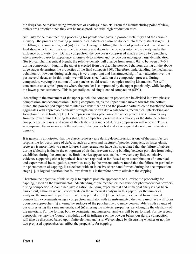
The second approach attempted to alleviate the occurrence of capping was to change the intrinsic material properties of the bulk blends. There are two ways to achieve this in practice: the first is to mix the lactose powder with another excipient, and the other is to replace lactose with a different excipient completely. Either approach will not only alter the intrinsic material properties, such as elasticity and plasticity, but also change the bonding mechanisms of the blends, which would be also beneficial for making a good tablet without defects. For example, as shown in Ref. [2], the tensile strength could be increased by mixing a powders of low bonding strength with ones of high bonding strength. In this study, we will change the Young’s modulus of the powder only and explore whether the change in Young’s modulus will affect the powder behaviour during compaction. We will ignore any changes in bonding mechanism, as these cannot easily be represented in the finite element simulation. Again we consider the compaction of a powder bed with initial height of 6mm into a height of 3mm at maximum compression. The diameter of the powder bed was 8mm and only flat-faced tablets were considered. Figure 9 shows the force-displacement relation during compaction of powders with different Young’s modulus. It is clear that, as might be expected, the maximum compression force decreases as the Young’s modulus decreases.
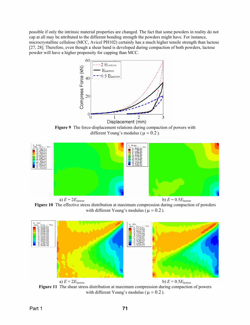
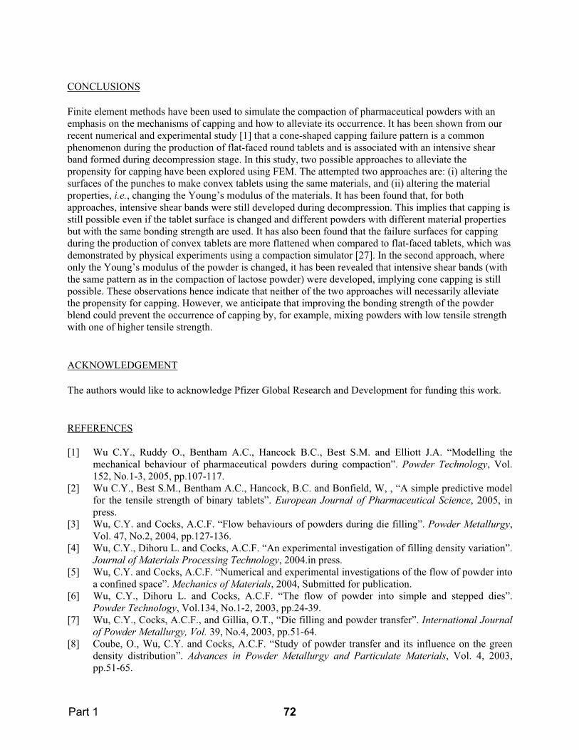
Figure 10 shows the effective stress distribution at maximum compression during the compaction of powders of different Young’s modulus. It is clear that, although the actual values of stress are different, the patterns are similar for compaction of powders with different Young’s modulus as the maximum stresses concentrate at the top edge of the tablets and minimum stress around the bottom edge (see also Fig. 7a), due to the influence of die wall friction. The shear stress distributions during decompression of powders with different Young’s modulus are given in Fig.11. It is evident that there are intensive shear bands as in the compaction of lactose powder (see Fig.8a), which implies that cone-capping will still be
Part 1 70
possible if only the intrinsic material properties are changed. The fact that some powders in reality do not cap at all may be attributed to the different bonding strength the powders might have. For instance, microcrystalline cellulose (MCC, Avicel PH102) certainly has a much higher tensile strength than lactose [27, 28]. Therefore, even though a shear band is developed during compaction of both powders, lactose powder will have a higher propensity for capping than MCC.
Figure 9 The force-displacement relations during compaction of powers with different Young’s modulus ( 2.0 ).
a) E = 2Elactose b) E = 0.5ElactoseFigure 10 The effective stress distribution at maximum compression during compaction of powders
with different Young’s modulus ( 2.0 ).
a) E = 2Elactose b) E = 0.5ElactoseFigure 11 The shear stress distribution at maximum compression during compaction of powers
with different Young’s modulus ( 2.0 ).
Part 1 71
CONCLUSIONS
Finite element methods have been used to simulate the compaction of pharmaceutical powders with an emphasis on the mechanisms of capping and how to alleviate its occurrence. It has been shown from our recent numerical and experimental study [1] that a cone-shaped capping failure pattern is a common phenomenon during the production of flat-faced round tablets and is associated with an intensive shear band formed during decompression stage. In this study, two possible approaches to alleviate the propensity for capping have been explored using FEM. The attempted two approaches are: (i) altering the surfaces of the punches to make convex tablets using the same materials, and (ii) altering the material properties, i.e., changing the Young’s modulus of the materials. It has been found that, for both approaches, intensive shear bands were still developed during decompression. This implies that capping is still possible even if the tablet surface is changed and different powders with different material properties but with the same bonding strength are used. It has also been found that the failure surfaces for capping during the production of convex tablets are more flattened when compared to flat-faced tablets, which was demonstrated by physical experiments using a compaction simulator [27]. In the second approach, where only the Young’s modulus of the powder is changed, it has been revealed that intensive shear bands (with the same pattern as in the compaction of lactose powder) were developed, implying cone capping is still possible. These observations hence indicate that neither of the two approaches will necessarily alleviate the propensity for capping. However, we anticipate that improving the bonding strength of the powder blend could prevent the occurrence of capping by, for example, mixing powders with low tensile strength with one of higher tensile strength.
ACKNOWLEDGEMENT
The authors would like to acknowledge Pfizer Global Research and Development for funding this work.
REFERENCES
[1] Wu C.Y., Ruddy O., Bentham A.C., Hancock B.C., Best S.M. and Elliott J.A. “Modelling the mechanical behaviour of pharmaceutical powders during compaction”. Powder Technology, Vol. 152, No.1-3, 2005, pp.107-117.
[2] Wu C.Y., Best S.M., Bentham A.C., Hancock, B.C. and Bonfield, W, , “A simple predictive model for the tensile strength of binary tablets”. European Journal of Pharmaceutical Science, 2005, in press.
[3] Wu, C.Y. and Cocks, A.C.F. “Flow behaviours of powders during die filling”. Powder Metallurgy,Vol. 47, No.2, 2004, pp.127-136.
[4] Wu, C.Y., Dihoru L. and Cocks, A.C.F. “An experimental investigation of filling density variation”. Journal of Materials Processing Technology, 2004.in press.
[5] Wu, C.Y. and Cocks, A.C.F. “Numerical and experimental investigations of the flow of powder into a confined space”. Mechanics of Materials, 2004, Submitted for publication.
[6] Wu, C.Y., Dihoru L. and Cocks, A.C.F. “The flow of powder into simple and stepped dies”. Powder Technology, Vol.134, No.1-2, 2003, pp.24-39.
[7] Wu, C.Y., Cocks, A.C.F., and Gillia, O.T., “Die filling and powder transfer”. International Journal of Powder Metallurgy, Vol. 39, No.4, 2003, pp.51-64.
[8] Coube, O., Wu, C.Y. and Cocks, A.C.F. “Study of powder transfer and its influence on the green density distribution”. Advances in Powder Metallurgy and Particulate Materials, Vol. 4, 2003, pp.51-65.
Part 1 72

[9] Wu, C.Y., Cocks, A.C.F. and Gillia, O.T., “Experimental and numerical investigations of die filling and powder transfer”. Advances in Powder Metallurgy and Particulate Materials, Vol. 4, 2002, pp.258-272.
[10] Coube, O., Cocks, A.C.F. and Wu, C.Y. “Experimental and numerical study of die filling, powder transfer and die compaction”, Powder Metallurgy, 2005, in press.
[11] Alderborn, G., and Nystrom, C., Pharmaceutical powder compaction technology, Marcel Dekker Inc., New York, 1996.
[12] Aydin, I., Briscoe, B. J., and Sanlitürk, K.Y., “The internal form of compacted ceramic components: a comparison of a finite element modelling with experiment”, Powder Technology, Vol. 89, 1996, pp.239-254.
[13] Aydin, I., Briscoe, B. J. and Ozkan, N., “Modelling of powder compaction: a review”, MRS Bulletin1997, pp.45-51.
[14] PM MODNET Research Group, “Numerical simulation of powder compaction for two multilevel ferrrous parts, including powder characterisation and experimental validation”, Powder Metallurgy,Vol.45, 2002, pp.335-343.
[15] PM MODNET Computer Modelling Group, “Comparison of computer models representing powder compaction process”, Powder Metallurgy, Vol.42, 1999, pp.301-311.
[16] Coube, O., and Riedel. H., “Numerical simulation of metal powder die compaction with special consideration of cracking”, Powder Metallurgy, Vol.43, 2000, pp.123-131.
[17] Zavaliangos, A., “Consitutive models for th esimulation of P/M process”. The 2002 Internation Conference on Process Modelling in Powder Metallugy & Particulate Materials, Princeton, NJ, MPIF, 2002.
[18] Sinka, I. C., Cunningham, J. C., Zavaliangos, A., “The effect of wall friction in the compaction of pharmaceutical tablets with curved faces: a validation study of the Drucker-Prager cap model”, Powder Technology Vol.133, 2003, pp. 33-43.
[19] Michrafy, A., Ringenbacher, D. and Techoreloff, P., “Modelling the compaction behaviour of powders: Application to pharmaceutical powders”, Powder Technology, Vol.127, 2002, pp.257-266.
[20] Drucker, D. C. and Prager, W., “Soil mechanics and plastic analysis or limit design”, Quarterly of Applied Mathematcs, Vol.10, 1952, pp.157-165.
[21] Schofield, A.N., and Wroth, C.P., Critical State Soild Mechanics, McGraw-Hill, London, 1968. [22] DiMaggio, F.L. and Sandler, I.S., “Material model for granular soils”, Journal of Engineering
Mechanics, ASCE, Vol.96, 1971, pp.935-950.[23] ABAQUS Theory Manual, Version. 6.4, HKS Inc, 2004. [24] Nedderman, R.M. Statics and Kinematics of Granular Materials, Cambridge University Press, New
York, 1992. [25] Zahlan, N. Knight, D.T., Backhouse, A. and Leiper, G.A., “Modelling powder compaction and
pressure cycling”, Powder Technology, Vol.114, 2001, pp.112-117.[26] Wu C.Y., Elliott J.A. Bentham A.C., Best S.M. Hancock B.C. and Bonfield W., “A numerical study
on the mechanical behaviour of pharmaceutical powders”. Proc. Int. conf. on Pharmaceutics, Biopharmaceutics and Pharmaceutical Technology, Nuremberg, Germany, 15-18 March 2004, pp.17-18.
[27] Wu C.Y., Mills, A., Hancock B.C., Bentham A.C., Best S.M., Elliott J.A. and William Bonfield, “Numerical and experimental investigation of capping mechanisms during tablet compaction”, Powder Technology, 2005, to appear.
[28] Tye, C.K, Sun, C. and Amindon, G.E., “Evaluation of the effects of tabletting speed on the relationships between compaction pressure, tablet tensile strength, and tablet solid fraction”, J. Pharm. Sci., Vol. 94, No.3, 2005, pp.465-472
Part 1 73