p0708ceicbvi v5.indd - learn digital
TRANSCRIPT
The Academy of Dental Therapeutics and Stomatology is an ADA CERP Recognized Provider
1-888-INEEDCE
Earn
4 CEUsThis course was
written for dentists, dental hygienists,
and assistants.
A Clinician’s Guide to Understanding Cone Beam Volumetric Imaging (CBVI)A Peer-Reviewed Publication Written by Dale A. Miles, DDS, MS, FRCD(C) and Robert A. Danforth, DDS
A Clinician’s Guide
This course has been made possible through an unrestricted educational grant from PLANMECA USA, Inc. The cost of this CE course is $59.00 for 4 CEUs. Cancellation/Refund Policy: Any participant who is not 100% satisfied with this course can request a full refund by contacting the Academy of Dental Therapeutics and Stomatology in writing.
2 www.ineedce.com
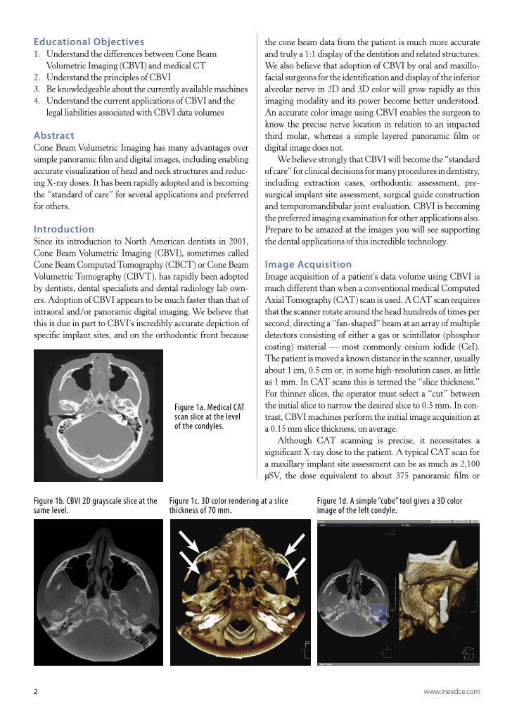
Educational Objectives1. Understand the differences between Cone Beam
Volumetric Imaging (CBVI) and medical CT2. Understand the principles of CBVI 3. Be knowledgeable about the currently available machines4. Understand the current applications of CBVI and the
legal liabilities associated with CBVI data volumes
AbstractCone Beam Volumetric Imaging has many advantages over simple panoramic film and digital images, including enabling accurate visualization of head and neck structures and reduc-ing X-ray doses. It has been rapidly adopted and is becoming the “standard of care” for several applications and preferred for others.
IntroductionSince its introduction to North American dentists in 2001, Cone Beam Volumetric Imaging (CBVI), sometimes called Cone Beam Computed Tomography (CBCT) or Cone Beam Volumetric Tomography (CBVT), has rapidly been adopted by dentists, dental specialists and dental radiology lab own-ers. Adoption of CBVI appears to be much faster than that of intraoral and/or panoramic digital imaging. We believe that this is due in part to CBVI’s incredibly accurate depiction of specific implant sites, and on the orthodontic front because
Figure 1a. Medical CAT scan slice at the level of the condyles.
Figure 1b. CBVI 2D grayscale slice at the same level.
Figure 1c. 3D color rendering at a slice thickness of 70 mm.
Figure 1d. A simple “cube” tool gives a 3D color image of the left condyle.
the cone beam data from the patient is much more accurate and truly a 1:1 display of the dentition and related structures. We also believe that adoption of CBVI by oral and maxillo-facial surgeons for the identification and display of the inferior alveolar nerve in 2D and 3D color will grow rapidly as this imaging modality and its power become better understood. An accurate color image using CBVI enables the surgeon to know the precise nerve location in relation to an impacted third molar, whereas a simple layered panoramic film or digital image does not.
We believe strongly that CBVI will become the “standard of care” for clinical decisions for many procedures in dentistry, including extraction cases, orthodontic assessment, pre- surgical implant site assessment, surgical guide construction and temporomandibular joint evaluation. CBVI is becoming the preferred imaging examination for other applications also. Prepare to be amazed at the images you will see supporting the dental applications of this incredible technology.
Image AcquisitionImage acquisition of a patient’s data volume using CBVI is much different than when a conventional medical Computed Axial Tomography (CAT) scan is used. A CAT scan requires that the scanner rotate around the head hundreds of times per second, directing a “fan-shaped” beam at an array of multiple detectors consisting of either a gas or scintillator (phosphor coating) material — most commonly cesium iodide (CeI). The patient is moved a known distance in the scanner, usually about 1 cm, 0.5 cm or, in some high-resolution cases, as little as 1 mm. In CAT scans this is termed the “slice thickness.” For thinner slices, the operator must select a “cut” between the initial slice to narrow the desired slice to 0.5 mm. In con-trast, CBVI machines perform the initial image acquisition at a 0.15 mm slice thickness, on average.
Although CAT scanning is precise, it necessitates a significant X-ray dose to the patient. A typical CAT scan for a maxillary implant site assessment can be as much as 2,100 µSV, the dose equivalent to about 375 panoramic film or

Figure 3a, 3b. Medical CT images of a proposed implant site.
www.ineedce.com 3
digital images.1 In contrast, the CBVI machines operate at much lower doses, ranging from about 40 to 500 µSv or as little as four to six panoramic equivalents.1
CBVI and the Hounsfield UnitIn 1972, Sir Godfrey Hounsfield invented a quantitative scale, a measure of the radiodensity of the body’s tissues that is still used to evaluate CAT scans today. Pixel data is displayed using this scale in terms of relative density. CBCT/CBVI data is treated a little differently.
“The pixel value is displayed according to the mean attenuation of the tissue that it corresponds to on a scale from –1024 to +3071 on the Hounsfield scale. Water has an attenuation of 0 Hounsfield units (HU), while air is –1000 HU, bone is typically +400 HU or greater, and metallic implants are usually +1000 HU.”5
CBVI, unlike CAT scanning, uses a “cone-shaped” beam aimed at a detector (an image intensifier (II), coupled to a CCD array or a flat-panel solid-state detector) that rotates around the patient either totally or partially. Image intensification is older technology. There are distortion patterns that must be “processed out” of the image for display, and the cesium io-dide (CsI) coating or in put phosphor will degrade slowly over time, making quality assurance an issue. Units employing II technology will require scintillator (in put phosphor) replace-ment over time.2 Flat-panel detectors are the newest image receptors for solid-state large-area arrays.3 These panels are currently expensive but have some advantages over the older II systems (Table 1).
Table 1. Advantages of flat-panel detectors over II systems.
• No image distortion • Smaller size of detector • Fewer components in imaging chain to add noise • Longer life span • Better dynamic range
Reconstruction images of the data acquired by CT are displayed in true Hounsfield units (HU), arbitrarily assign-ing gray shades from –1000 to +1000. This allows the data to display even the gray and white matter of the brain and to separate tissues of similar density by employing sophisticated computer algorithms. Though CBVI machines also display gray scale units, they are not “true” HU. The values assigned to the voxels (volume elements) are relative HU and cannot be used as precisely to estimate bone density. In fact, there is no good data to relate HU to the quality of bone for a desired implant site, although clinicians place great faith in the HU in an attempt to determine whether or not their implant fix-ture will be placed in “good bone.” Figure 1a shows a typical medical CAT scan slice at the level of the TMJ condyles; due to patient asymmetry, only the right condylar head is seen. Figure 1b shows a CBVI 2D grayscale slice at the same level. Figure 1c shows the 3D color rendering at a slice thickness
of 70 mm displaying more “anatomic” detail. Figure 1d shows a simple “cube” tool within the third-party software (OnDemand3D, CyberMed International). This gives a 3D color image of the left condyle simply and quickly.
Pixel vs. Voxel InformationA pixel (“picture element”) is a small rectangle, anywhere from 20 to 60 microns. The unit area is the same whether an intraoral sensor, a TFT screen or the II/solid-state combination device is used. CCDs and CMOS arrays for intraoral sensors are megapixel arrays; that is, they have 1 million pixels or more. In flat-panel detectors, for example the Planmeca ProMax 3D, there may be as many as 120 million pixels. However, the “pixel” in a CBVI machine is really a “voxel,” or volume element, sometimes described as an “iso-tropic pixel.” This unit area is a volume or cube with the same length on each side. In conventional medical CT the pixel is “non-isotropic”; it has two equal sides but the third, or “z”-plane, has a selectable width anywhere from 1.0 mm to 1.0 cm or more. The slice thickness of CBVI units is as little as 0.12 mm. An isotropic voxel has the same length, or dimension, on each side (Figure 2). The dimension of each side of the volume element for the CBVI would be only about 0.15 mm, or seven times thinner than the medical voxel on each side.
Figure 2. Pixel, medical CAT scan voxel, CBVI isotropic voxel.
CAT “voxel”Isotropicvoxel of
CBVTPixel
Cross-sectional images of a proposed implant site with these differing slice widths demonstrate the results. Medi-cal CT images of a proposed implant site show low image resolution, and the clinician must use a ruler to “count” the millimeters of height and width (Figures 3a, b). In contrast,

4 www.ineedce.com
size in megabytes for this data volume also varies. With CBVI the patient’s image data can range from 65MB to 250MB, also depending on detector size and the region-of-interest imaged. We look at as many as 512 slices or pictures in three orthogonal planes, or 1,500 slices, to detect occult pathology and report findings, both dental and non-dental! The data set is large and the time required to carefully examine and report is significant. Most dentists and dental specialists will not have the time to examine each volume data set.
Hard Tissues vs. Soft TissuesExcept for the skin surface, CBVI images are not very good for soft tissue display of tissues with similar densities. If the data could be displayed like true medical CT, then the dentist could not interpret this data with sufficient expertise. As it is, the amount of information “read” by oral and maxillo-facial radiologists requires an organized, systematic, diligent examination process to properly evaluate the data for occult findings. Our service “reads” the following for findings on every single case referred: paranasal sinuses, airway, nasal cavity, temporomandibular joint structures, ossseous struc-tures, dental structures, and other findings.
“Other findings” include pharyngeal and nasopharyn-geal masses; carotid calcifications, both atherosclerotic and Mönckeberg’s; and cranial calcifications. The findings are
the CBVI images show significant improvement in image resolution (Figures 3c, d). The clinician simply uses a rapid measurement tool to precisely label both the height and width of the site, accurate to within 0.10 mm and the inferior alveolar nerve is marked automatically in red for clear visualization.
Absorbed X-ray DoseCBVI doses range from 40 to 500 µSv depending upon the machine and volume size.3 Image acquisition using CBVI is very different compared to traditional CT scans because the kV and mA are much lower than with medical units. Table 2 shows the various exposure factors and image acquisition and data reconstruction times for the CBVI machines currently sold in North America.
Image DataAlthough the size of patient data volume is dependent upon the body part of interest in medical CT, the number of images per study (slices) ranges from 400 to 5,000.4 The actual file
Figure 3c, 3d. CBVI images of a proposed implant site.
Figure 4a. Conventional medical CT slice at the level of the superior surface of the condylar heads. The tips of the coronoid processes are just visible (arrows).
Figure 4b. 3D color reconstruction of the skull slightly superior to the slice level seen in Figure 4a.
EAC
S
Table 2. Applications for which CBVI is preferred.
• Impactions (Figure 5)• Inferior alveolar nerve location (Figure 5, 6)• Airway studies for sleep apnea (Figure 7)• Endodontic evaluation• Space analysis (because of the 1:1 image data of CBVI)• Paranasal sinus evaluation; maxillary sinus location (Figure 8)• Odontogenic lesion visualization• TMJ structure visualization (Figure 9)• Trauma evaluation (Figure 10)• TADs (temporary anchorage devices)• 3D virtual models• Other CAD/CAM devices• Bone structure (dehiscence, fenestration, periodontal defects)

www.ineedce.com 5
Figure 5b. Molar impactions and inferior alveolar nerve location.
Figure 5a. Cuspid impaction, palate.
Figure 6. Inferior alveolar nerve location. OKC in “cube modes” and endoscopy. All done in third party software (CyberMed International).
Thin section — grayscale image. 20 mm section in 3D color rendering
summarized, recommendations made where appropriate and images from the data set embedded in the report for the refer-ring clinician. Figure 4 compares CBVI images and medical CT images at the same slice level. Note the three-dimensional visualization of the coronoid process (arrow). The condylar heads lie just beneath the middle cranial fossa. The floor of
the sphenoid sinus (S) and the ethmoid air cells (EAC) are seen also.
It should be noted that many of the images seen in the center section of this article, for both large and small volume machines, have been performed using “third party” software called “OnDemand 3D” (CyberMed International, Seoul,

6 www.ineedce.com
Figure 7. Airway studies.
Large volume Airways Small volume
www.ineedce.com 7
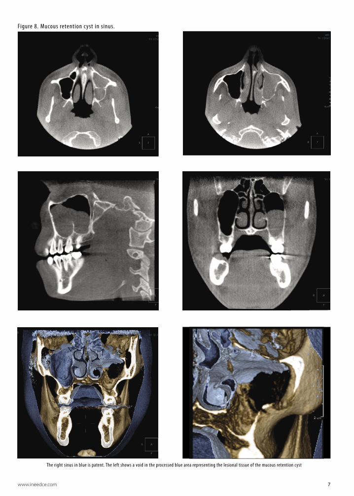
Figure 8. Mucous retention c yst in sinus.
The right sinus in blue is patent. The left shows a void in the processed blue area representing the lesional tissue of the mucous retention cyst

8 www.ineedce.com
Figure 9a, b, c. Normal condyle in large volume machine.
Axial slice at mid condyle and 3D color image of condylar head done in OnDemand3D software
i-CAT “panoramic” created in i-CAT Vision software
Coronal slice of case above but in OnDemand3D software
Korea). This is the software we use in our “reading service” and versions of this product are currently only available with the Hitachi, Iluma and Planmeca machines. Hitachi and Iluma use a version called “Accurex”, a single client platform. Planmeca has a version trademarked “N-Liten”, specifically designed for their ProMax3D CBVT machine. The software is also available directly from CyberMed. All large volume images seen are from Imaging Sciences i-CAT machines using exported DICOM data volumes. However, the 3D color large volume images displayed cannot be reconstructed using i-CAT’s current proprietary software sold with their machine.
Applications of CBVIThe list of current dental applications is long. In addition to the primary applications cited above for which we believe CBVI will become the “standard of care”, various authors have identi-fied other applications for which CBVI is preferred (Table 2).
Limitations of Cone Beam Imaging
Reduced Capability to Display Soft TissueSome might argue that the reduced capability to display soft tissue with CBVI is not a disadvantage because of the enor-

www.ineedce.com 9
Figure 9d.
J. Morita, small volume TMJ views
J. Morita, left and right TMJ condylar views
Planmeca ProMax 3D CBVT color TMJ views in N-Liten software. Left – at 10 mm slice thickness. Right – at 22.5 mm thickness to see condylar interior and condyle/fossa relationship
mous number of anatomic structures that a radiologist must master in order to expertly interpret the structures contained within the cranial vault. There are enough important bony and soft-tissue anatomic structures for dentists or dental specialists to contend with in the head and neck. In fact, most of the CBVI volumes we read are at the request of dentists and specialists who do not feel comfortable reviewing the skull contents and
wish to minimize or eliminate their liability by recruiting the expertise of an oral and maxillofacial radiologist. While gray and white matter is not visible, soft tissues such as muscles and glands, and mucosal change in the paranasal sinuses, are visual-ized quite well. Odontogenic lesions encroaching on the nasal cavity and paranasal sinuses can readily be more prominently visualized than with traditional plain film or digital images.
10 www.ineedce.com
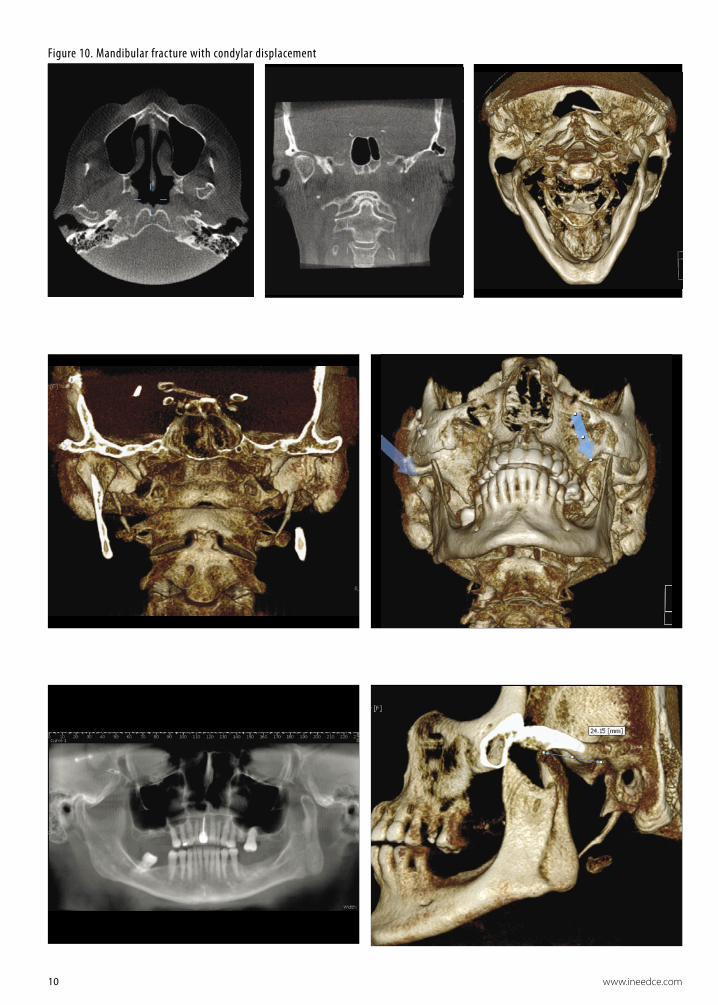
Figure 10. Mandibular fracture with condylar displacement

www.ineedce.com 11
Not all software is capable of 3D color display in great anatomic detail. Some simply use “surface rendering”, assigning a single color to make the image striking (Figure 11). Others, such as CyberMed International’s OnDemand3D, offer a higher-level software treatment by assigning color, transparency and opacity, which are customizable to make a more life-like 3D color rendering5 (Figure 12).
Machine Considerations and LimitationsThere are a number of machine considerations and limita-tions, including artifacts and calibration.
Artifacts
Scatter Radiation and Noise in CBVICBVI suffers artifacts similar to conventional medical CAT scans (Table 3). The amount of scatter from cone beam ma-
chines is much higher than the scatter from the “fan-shaped” beam used in medical CT imaging.6,7 Figure 13 contains the images of an orthodontic patient. These show scatter, fol-lowed by less scatter, following use of a software algorithm to “clean up” the scatter. Most companies use an “antiscatter” or “scatter-correction” algorithm. While CBVI reduces the absorbed X-ray dose, the higher levels of scattered radiation require pre-display image processing algorithms, such as the Feldkamp algorithm,8 to optimize image quality. Many newer scatter-reduction algorithms are under development for both small- and large-volume machines.9
“Cupping Artifact”X-rays from CBVI passing through the mid-portion of a cy-lindrical object such as an implant are “hardened” more than those passing through the edges of the object, because they pass though more material in the mid-portion. As the center
Figure 11. 3D color “surface rendered” mandible with calcified, elongated stylohyoid ligament on patient’s left side.
Figure 12. A typical 3D color rendering showing a more “anatomic” image of the styloid process and related structures.
Table 3.
Objects causing “scatter”
Objects not causing “scatter”
• Amalgam restorations• Braces• Prosthetic crowns• Endodontic silver points • Metallic “ball” markers• Lead foil used for implant marking• Barium sulphate (formerly used in to-
mography for implant site assessment)
• Most implant fixtures
• Gutta percha used in root canal therapy
• Gutta percha used as implant marker material
Figure 13a. Figure 13b.
Figure 13c.
Figure 13d.

12 www.ineedce.com
part of the beam is hardened, the rate of X-ray attenuation decreases and the beam reaching the detector is thus more intense. As a result, the attenuation profile differs from the ideal profile that would be obtained without beam hardening, and the profile of the CT numbers across the implant will display a characteristic cupped shape.
“Streaking”In CBVI cross-sections, primarily the axial slices, streaks can appear between two dense objects in an image. Since the portion of the beam that passes through one of the objects at certain X-ray tube positions will be hardened less than when it passes through both objects at other tube positions, streak artifacts are generated. This type of artifact occurs primarily in bony regions and where metallic restorations are located.
Calibration Requirements Some CBVI machines require daily or even twice-daily calibration. Manuals for machines such as the Imaging Sci-ences i-CAT suggest a morning and afternoon calibration. This could reduce the productivity of a busy imaging labo-ratory. More importantly, if calibration is not performed as part of a quality assurance program, scans could have to be repeated due to image artifacts. Machines such as the Planmeca ProMax3D and the Morita Accuitomo do not require calibration.
Image Intensification vs. Solid-StateFlat-panel detectors, largely amorphous silicon (a-Si:H) panels, have a higher “collection efficiency” for incident X-rays or photoelectrons than indirect designs such as IIs.
Indirect capture devices have an estimated 50% efficiency, whereas direct detectors such as flat-panel detectors claim almost 98% efficiency for the charge collected in the photoconductor layer.10 This efficiency may be one of the reasons that image quality is improved in direct systems. In addition, as stated previously, the in put phosphors in II systems degrade over time, ultimately resulting in reduced image quality and the need to replace the II itself.
Machine SizeFor anyone planning to purchase a CBVI machine, its size or “ergonomic footprint” may be a significant consideration. Some machines, such as the Hitachi CBMercuray, have more robust imaging capability, but with that capability comes a large unit size. The CBMercuray can perform “real-time” imaging, such as of swallowing or movement of the condyle, but the machine weighs one ton. It cannot be placed in offices on upper stories where the load tolerances of the floor (office ceiling below) are inadequate. With other machines, such as the Planmeca ProMax3D, CBVI is simply accomplished by a detector “swap,” making it the most ergonomic device available. In addition, this machine is the only cone beam device that is upgradeable from an existing panoramic platform. Between these two “extremes” are many other CBVI machines. The machine parameters for various CBVI machines are shown in Table 4.
Machine Parameters: Volume SizeMany clinicians think they need a “large-volume” CBVI ma-chine. In fact, most do not. You must consider the following questions when making your selection:1. How much data (how many images) do you need?
Table 4 – Machine Parameters
Scanner name
Manufac-turer
Detector type
Detector size
(cm.) maxi-mum
Voxel size mm3
Scan Time (s)
Exp. Time (s)*
Recon-struc-tion time (min-utes)
kV mA Focal spot
Weight Lbs.
Accuitomo J. Morita TFT 6 × 6 0.125 18 18 5.0 60 – 80 1 – 10 0.5 882
CBMercuray Hitachi II/CCD 10.2 – 19 0.2 – 0.38 10 10 6.0 60 – 120 10/15 Not
given 2,000
Galileos Sirona II/CCD 15 × 15 0.15 – 0.3 14 14* 4.5 85 5 – 7 Not given 352
Iluma Imtec TFT 19 × 24 0.09 – 0.4 10 – 40 10 – 40 4.0 at 0.4 voxel 120 3.8 0.3 770
I Cat Imaging Sciences TFT? 20 × 25 0.12 – 0.4 5 – 25 3 – 8* < 1 120 1-3 0.5 425
NewTom VG AFP TFT 15 × 16 0.16 – 0.32 20 5.4 3.0 110 15 0.3 550
ProMax3D Planmeca TFT/CMOS 8 × 8 0.16 16 – 18 6* < 3 84 12 0.5 248
Scanora 3D Soredex II/CCD 7.5 × 14.5 0.15 – 0.35 20 5 3 85 8 0.4 690
* The ProMax3D, Galileos, and it is thought, the i-CAT use a “pulsed exposure”, turning the radiation source off and on at intervals. This lowers the overall radiation absorbed dose substantially.

www.ineedce.com 13
2. How large an area do you wish to evaluate?3. Do you need simple 2D grayscale information for
your decision?4. Does the diagnostic task really require CBVI?5. Does every patient require this type of imaging?6. Are you comfortable “diagnosing” all of the data?7. What is your risk of missing an important occult finding? 8. What is the impact on your office workflow?
We will offer a brief discussion of the impact of these questions on your decision to purchase and/or prescribe CBVI.
Not all diagnostic tasks require a cone beam image data set. Simple evaluation of the TMJ surfaces prior to adult orthodontic treatment can probably be addressed by a well-positioned, well-exposed panoramic radiograph. Similarly, determining if third molars are present probably does not require use of CBVI. Not all orthodontists or oral surgeons want to wait 6–10 minutes for image acquisition and image reconstruction just to make an initial assessment. Nor do they have the time to “scroll” though hundreds of slice data to find a panoramic image on which to view the condyles or third molars.
By the same token, a clinician placing only a few implant fixtures per month does not want to assume the cost of the machine. In an office that currently uses images for caries detection and periodontal evaluation, the workflow would be seriously slowed if the dentist had only a cone beam machine for all his/her radiographic needs. It would not make sense or be productive. CBVI, in our opinion, will not replace intraoral or panoramic radiography. All of these techniques are complementary, not exclusionary. One X-ray device will not handle all imaging needs. It hasn’t happened in medicine. It will not happen in dentistry either.
If you do use CBVI for the appropriate tasks, be prepared to look at an enormous amount of image data. You cannot abrogate your responsibility for any occult pathology or reportable finding by having the patient sign a form saying you are not trained to look at all the head and neck data. You must be prepared to look at all the images to see if there are significant changes or findings, describe these findings and take the appropriate action. This may simply be a referral for treatment or for additional evalu-ation to another specialist if an area looks unusual. What you cannot afford to do is miss a finding and thus put you and your practice, as well as the laboratory or colleague who may have performed the image acquisition, at signifi-cant risk. The reader is re-directed to the questions above to determine his/her “comfort level” with adopting cone beam technology in the office.
Final ThoughtsThere is no doubt that this is the most exciting imaging technology to come to our profession in the past 20 years.
Many clinicians will embrace this technology because of the wide number of applications, better decision-making data and lower radiation dose. However, like any other technol-ogy adoption, you must first educate yourself about the technology and determine how it could improve your prac-tice and treatment of your patients. Only then can you attain the comfort level necessary to use the technology skillfully. We hope that this article helps you to achieve this goal.
References1 Ludlow JB, Davies-Ludlow LE, Brooks SL, Howerton WB. Dosimetry of 3 CBCT devices for oral and
maxillofacial radiology: CB Mercuray, NewTom 3G, and i-CAT. Dentomaxillofac Radiol. 2006;35:219–226. 2 Correction statement for dose units. Dentomaxillofac Radiol. 2006;35:392. 3 de Groot PM. Image intensifier design and specifications, Thales Electron Devices, Moirans, France, 1991.4 Wang J, Blackburn TJ. The AAPM/RSNA physics tutorial for residents: X-ray image intensifiers for
fluoroscopy. RadioGraphics 2000;20:1471–1477.5 Fishman EK, Ney DR, Heath DG, Corl FM, Horton KM, Johnson PT. Volume rendering versus maximum
intensity projection in CT angiography: what works best and why. RadioGraphics. 2006;26:905–922.6 Rinkel J, Esteve F, Dinten JM. Evaluation of a physical based approach of scattered radiation correction
in cone beam CT for non-destructive testing applications. ECNDT Poster #39, Proceedings of the ECNDT Conference 11(11), Berlin 2006.
7 Endo M, Tsunoo T, Nakamori N, Yoshida K. Effect of scattered radiation on image noise in cone beam CT. Med Physics. 2001;28:469–474.
8 Xiao S, Bresler Y, Munson DC. Fast Feldkamp algorithm for Cone-Beam Computer Tomography. Dept. of Electrical and Computer Engineering and Coordinated Science Library, University of Illinois at Urbana-Champaign, U.S. Army Research Office, contract 38310-PH DAAG55-98-1-0039.
9 Yang D, Ning R. FDK Half-scan with heuristic weighting scheme on a flat panel detector-based cone beam CT (FDKHSCW). Int J Biomedical Imaging. 2006;2006:1–8.
10 Yorkston J. Digital radiographic technology, advances in digital radiography: RSNA categorical course in diagnostic radiology physics 2003;23–36.
Author Profiles
Dale A. Miles, DDS, MS, FRCD(C)Dale A. Miles, DDS, MS, FRCD(C), is in full-time practice of oral and maxillofacial radiology in Fountain Hills, Ariz., and is an adjunct professor at the Arizona School of Dentistry and Oral Health in Mesa and the University of Texas Health Sciences Center in San Antonio. He is a diplomate of both the American Board of Oral and Maxillofacial Radiology and the American Board of Oral Medicine.
Robert A. Danforth, DDSRobert A. Danforth, DDS, is an oral radiology laboratory owner in California and an associate professor of radiology at the University of Nevada, Las Vegas, School of Dental Medicine. He is a diplomate of the American Board of Oral and Maxillofacial Pathology.
DisclaimerThe authors of this course have no commercial ties with the sponsors or the providers of the unrestricted educational grant for this course.
Reader FeedbackWe encourage your comments on this or any ADTS course. For your convenience, an online feedback form is available at www.ineedce.com.

14 www.ineedce.com
Questions
1. Cone Beam Volumetric Imaging (CBVI) was first introduced to North American dentists in _____.a. 1997b. 1999c. 2001d. 2003
2. A head and neck CAT scan _____.a. requires that the scanner rotate around the head
hundreds of times per secondb. directs a “fan-shaped” beam at an array of
multiple detectorsc. is the most recent method of imaging availabled. a and b
3. CBVI machines currently can perform the initial image acquisition at a slice thickness of as little as _____.a. 0.12 mmb. 0.15 mmc. 0.25 mmd. 0.5 mm
4. CBVI absorbed X-ray doses typically range from _____.a. 20 – 40 μSvb. 40 – 50 μSvc. 40 – 500 μSvd. 500 – 2,100 μSv
5. The quantitative scale used to evaluate CAT scans was invented by _____.a. Sir Hillary Edmundb. Sir Walter Raleighc. Sir Godfrey Houndsworthd. Sir Godfrey Hounsfield
6. CBVI uses a “cone-shaped” beam _____.a. at the detectorb. coupled to a CCD array or flat-panel solid-state
detectorc. that results in no distortiond. a and b
7. The newest image receptors for solid-state large-area arrays are _____.a. image intensifier systemsb. flat-panel detectorsc. cesium cylindersd. a and c
8. CBVI machines display gray scale units that _____.a. are true Hounsfield unitsb. are not true Hounsfield unitsc. can be used precisely to estimate bone densityd. a and c
9. CBVI has a volume element known as a _____.a. poxelb. voxelc. isotropic voxeld. paxel
10. CBVI X-ray doses ______________.a. range from 30 to 300 μSvb. depend upon the machine and volume size c. range from 40 to 500 μSv d. b and c
11. The number of images (slices) per study using medical CT _____.a. ranges from 400 to 5,000b. results in the actual file size in megabytes being
constantc. is less than with conventional film radiography d. can be reduced with altered voltages
12. Using CBVI, the number of slices in total examined in three orthogonal planes is approximately _____.a. the same as using medical CTb. up to 1,500 slicesc. less than using medical CTd. none of the above
13. CBVI images _____.a. are not very good for soft tissue display of
tissues with similar densitiesb. are good for display of the skin surfacec. suffer artifacts similar to those of conventional
medical CAT scansd. all of the above
14. Findings read on every single case using CBVI should at a mimimum include _____.a. paranasal sinuses, nasal cavity and airwaysb. TMJ structuresc. osseous and dental structuresd. all of the above
15. “Other” findings read on cases using CBVI may include _____.a. carotid calcificationsb. cranial calcificationsc. pharyngeal massesd. all of the above
16. Some “third party” software allows the radiologist to:a. render 3D color images of pathologyb. assign color, opacity and transparency to voxelsc. only use “surface rendering” for colord. a and b
17. Applications for which CBVI is preferred in dental settings, in addition to those where it is believed by the authors that it will become “standard of care,” include _____.a. inferior alveolar nerve locationb. trauma evaluationc. orbital evaluationd. a and b
18. All software used with CBVI is capable of 3D color display in great anatomic detail. a. Trueb. False
19. Scatter radiation _____.a. results in artifacts in both medical CAT scans
and CBVIb. results in artifacts in only CBVIc. does not result in artifactsd. only occurs with non-metallic substances
20. Scatter radiation _____.a. is caused by metallic objects such as amalgam
restorationsb. is corrected for using software algorithmsc. is of no consequenced. a and b
21. “Cupping artifacts” occur _____.a. only when a circular object is being imagedb. because X-rays from CBVI passing through the
midpoints of cylindrical objects are “hardened” more than those passing through the edges of the object
c. only because the cone beam machine is not properly calibrated
d. a and b
22. “Streaking” _____.a. can appear between two thin objects in an image b. can appear between two dense objects in an
imagec. occurs primarily in bony regionsd. b and c
23. Some cone beam machines must be calibrated twice-daily.a. Trueb. False
24. If calibration is required and not performed, _____.a. patients are at serious risk of the machine
collapsingb. scans may have artifacts as a resultc. scans may need to be repeatedd. all of the above
25. Machines that do not require calibra-tion include the _____.a. Planmeca ProMax3Db. Curarayc. Morita Accurae. a and c
26. Flat-panel detectors _______.a. have a higher “collection efficiency” than
indirect designs dob. claim almost 98% efficiency for the charge
collected in the photo-conductor layerc. are the oldest technology availabled. a and b
27. Image intensifiers _____.a. are older technology than flat-panel detectorsb. need to be replaced over time because the input
phosphors degrade over timec. a and bd. none of the above
28. If a CBVI machine weighs one ton, _____.a. it always has less robust imaging capability than
lighter machines do b. the load tolerances of the floor must be
consideredc. it cannot be used for dental imagingd. a and b
29. In considering CBVI, a factor that should be considered is _____.a. how often it would be usedb. whether it is better to refer patients out for
CBVI c. the impact on office workflowd. all of the above
30. If you use CBVI, _____.a. you must be prepared to interpret all the data on
the images b. you must be prepared to describe the findings
and take appropriate actionc. be sure to have the patient sign a form indicating
that you cannot interpret all head and neck datad. a and b
www.ineedce.com 15
PLEASE PHOTOCOPY ANSWER SHEET FOR ADDITIONAL PARTICIPANTS.
For IMMEDIATE results, go to www.ineedce.com and click on the button “Take Tests Online.” Answer sheets can be faxed with credit card payment to (440) 845-3447, (216) 398-7922, or (216) 255-6619.
Payment of $59.00 is enclosed. (Checks and credit cards are accepted.)
If paying by credit card, please complete the following: MC Visa AmEx Discover
Acct. Number: _______________________________
Exp. Date: _____________________
Mail completed answer sheet to
Academy of Dental Therapeutics and StomatologyP.O. Box 116, Chesterland, OH 44026
or fax to: (440) 845-3447
Educational Objectives1. Understand the differences between Cone Beam Volumetric Imaging (CBVI) and medical CT
2. Understand the principles of CBVI
3. Be knowledgeable about the currently available machines
4. Understand the current applications of CBVI and the legal liabilities associated with CBVI data volumes
Course EvaluationPlease evaluate this course by responding to the following statements, using a scale of Excellent = 5 to Poor = 0.
1. Were the individual course objectives met? Objective #1: Yes No Objective #3: Yes No
Objective #2: Yes No Objective #4: Yes No
2. To what extent were the course objectives accomplished overall? 5 4 3 2 1 0
3. Please rate your personal mastery of the course objectives. 5 4 3 2 1 0
4. How would you rate the objectives and educational methods? 5 4 3 2 1 0
5. How do you rate the author’s grasp of the topic? 5 4 3 2 1 0
6. Please rate the instructor’s effectiveness. 5 4 3 2 1 0
7. Was the overall administration of the course effective? 5 4 3 2 1 0
8. Do you feel that the references were adequate? Yes No
9. Would you participate in a similar program on a different topic? Yes No
10. If any of the continuing education questions were unclear or ambiguous, please list them.
___________________________________________________________________
11. Was there any subject matter you found confusing? Please describe.
___________________________________________________________________
___________________________________________________________________
12. What additional continuing dental education topics would you like to see?
___________________________________________________________________
___________________________________________________________________
ANSWER SHEET
A Clinician’s Guide to Understanding Cone Beam Volumetric Imaging (CBVI)
Name: Title: Specialty:
Address: E-mail:
City: State: ZIP:
Telephone: Home ( ) Office ( )
Requirements for successful completion of the course and to obtain dental continuing education credits: 1) Read the entire course.2) Complete all information above. 3) Complete answer sheets in either pen or pencil. 4) Mark only one answer for each question. 5) A score of 70% on this test will earn you 4 CEUs. 6) Complete the Course Evaluation below. 7) Make check payable to The Academy of Dental Therapeutics and Stomatology OR PennWell Corp.
AGD Code 731
AUTHOR DISCLAIMERThe authors of this course have no commercial ties with the sponsors or the providers of the unrestricted educational grant for this course.
SPONSOR/PROVIDERThe Academy of Dental Therapeutics and Stomatology, Inc. (ADTS) is the only sponsor/provider. This course was made possible through an unrestricted educational grant from PLANMECA USA, Inc. No manufacturer or third party has had any input into the development of course content. All content has been derived from references listed, and or the opinions of clinicians. Please direct all questions pertaining to the ADTS or the administration of this course to Machele Galloway, 1421 S. Sheridan Rd., Tulsa, OK 74112 or [email protected]
INSTRUCTIONSAll questions should have only one answer. Grading of this examination is done manually. Participants will receive confirmation of passing by receipt of a certificate. Certificates will be mailed within two weeks after taking an examination.
EDUCATIONAL DISCLAIMERThe opinions of efficacy or perceived value of any products or companies mentioned in this course and expressed herein are those of the author(s) of the courses and do not necessarily reflect those of the ADTS. Completing a single continuing education course does not provide enough information to give the participant the feeling that s/he is an expert in the field related to the course topic. It is a combination of many educational courses and clinical experience that allows the participant to develop skills and expertise.
COURSE CREDITS/COSTAll participants scoring at least 70% (answering 21 or more questions correctly) on the examination will receive a certificate verifying 4 CEUs. The formal continuing education program of this sponsor is accepted by the AGD for Fellowship/Mastership credit. Please contact ADTS for current term of acceptance. Participants are urged to contact their state dental boards for continuing education requirements.
COURSE EVALUATIONWe encourage participant feedback pertaining to all courses. Please be sure to complete the survey included with the course.
PARTICIPANT FEEDBACKPlease e-mail all questions to: [email protected].
RECORD KEEPINGThe ADTS maintains records of your successful completion of any exam. Please contact our offices for a copy of your continuing education credits report. This report, which will list all credits earned to date, will be generated and mailed to you within five business days of receipt.
CANCELLATION/REFUND POLICYAny participant who is not 100% satisfied with this course can request a full refund by contacting the Academy of Dental Therapeutics and Stomatology in writing.
© 2007 by the Academy of Dental Therapeutics and Stomatology
CONE0708DE