p14254: underwater thermoelectric power generationedge.rit.edu/edge/p14254/public/design/msd ddr...
TRANSCRIPT

P14254: Underwater Thermoelectric Power Generation
Team: Charles Alexander, Tom Christen, Kim Maier, Reggie Pierce, Matt Fister, Zach Mink Guide: Rick Lux

Agenda
• DDR Objectives • Review Project Goals • Electrical Design • Mechanical Design • Manufacturing, Assembly, Test Plans • Bill of Materials • Risk Assessment • MSD II Project Schedule
DDR Objectives
From this review, we hope to:
• Ensure conduit/wire connections are sensible
• Check that testing plans seem feasible

Project Goals
• Demonstrate proof of concept of thermoelectric system
• Use a temperature differential to charge a battery
• Achieve maximum thermoelectric efficiency over a range of temperatures
• Establish a UUV-based research partnership between Boeing and RIT

Electrical Design

Battery
• Purchased HP 6-Cell Li-Ion Laptop Battery
• 10.8V and 55 Whr
• Li-ion expert expresses concern in charging method
• Smart Battery Communication
– Pinout
– Road-Block
Battery
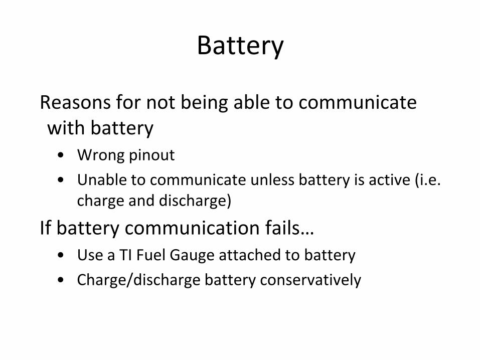
Reasons for not being able to communicate with battery
• Wrong pinout
• Unable to communicate unless battery is active (i.e. charge and discharge)
If battery communication fails… • Use a TI Fuel Gauge attached to battery
• Charge/discharge battery conservatively

Battery Safety
• Li-Ion are normally charged in a CC-CV modes
• Increased risk involved with constant power
– Overcharge
– Battery Damage
• Risk Mitigation
– Confirm Simulink model
– Software overvoltage protection in conjunction with HP protection circuit
– Conservative Charge/Discharge controlled by software
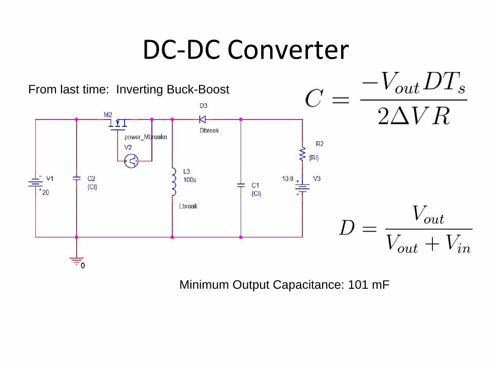
DC-DC Converter From last time: Inverting Buck-Boost
Minimum Output Capacitance: 101 mF
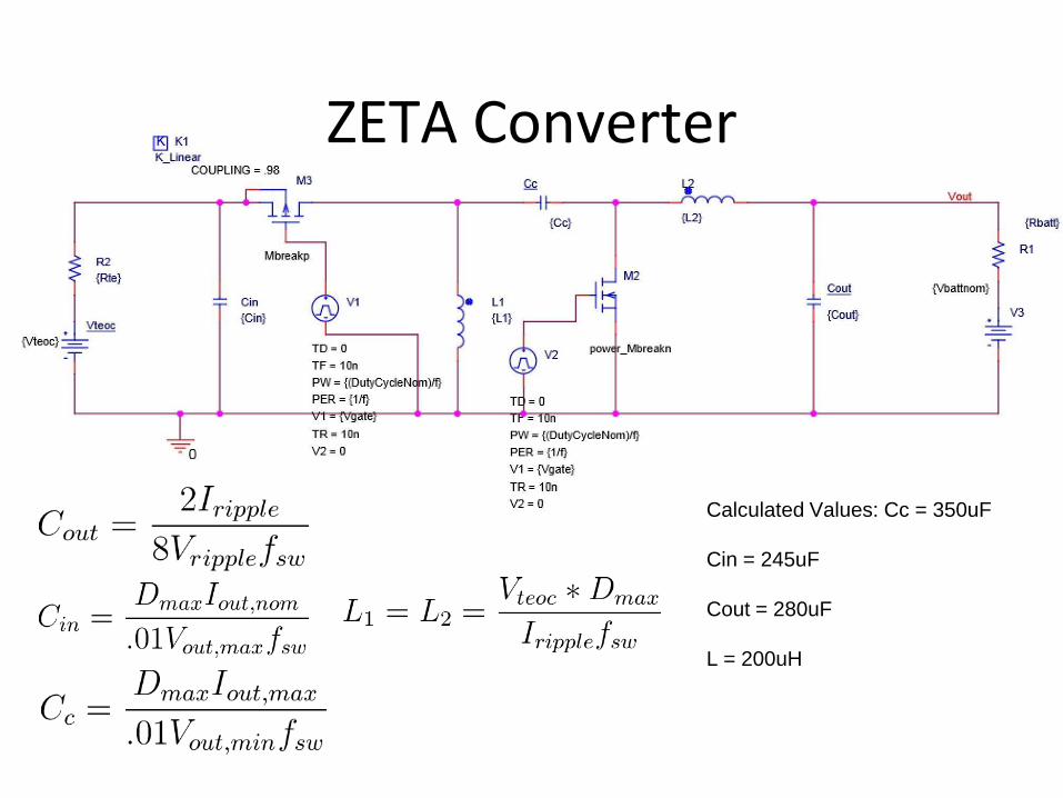
ZETA Converter
Calculated Values: Cc = 350uF
Cin = 245uF
Cout = 280uF
L = 200uH

SPICE Simulation
With predicted component values: ~10mV output ripple voltage
● Adjusting components until maximum ripple obtained: 120uF
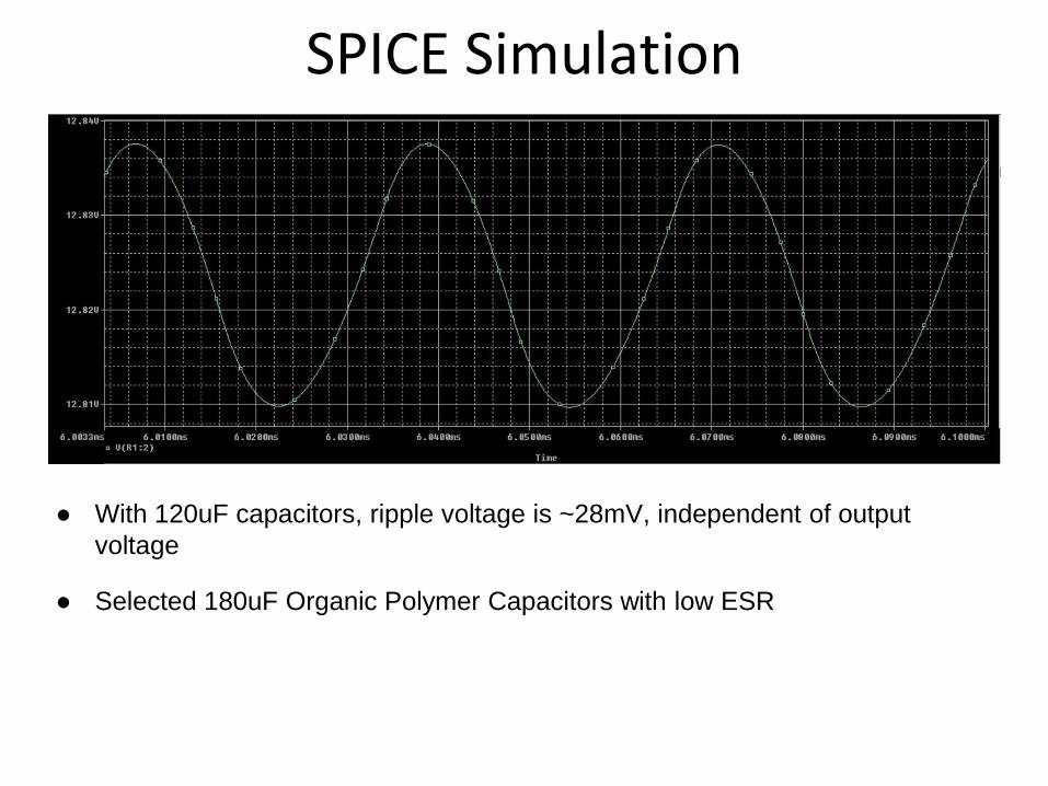
● With 120uF capacitors, ripple voltage is ~28mV, independent of output
voltage
● Selected 180uF Organic Polymer Capacitors with low ESR
SPICE Simulation

Current Sensing Typical Resolution of Hall Effect Resolution -
Equivalent to:
For the same resolution, i.e. , the resulting
power dissipation is:
For the same Hall Effect Sensor, rated power
consumption/dissipation is ~12mW
How does resolution affect data being read?
10 bit ADC, 5V reference:
For a 1A signal from the sensor - equivalent to a current
resolution or “uncertainty” of :
In terms of power, this can be thought of as an
uncertainty of:
Found a 24 bit ADC - Linear Technology
(Ultra low power consumption)
Following the same process, resulting
measured power uncertainty is reduced to
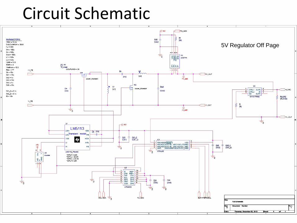
Circuit Schematic
5V Regulator Off Page

Hall Effect Sensor

Controller & ADC

To Program the Controller...
● Sparkfun “Tiny AVR Programmer”
● Can be used for Prototyping
● Free!

DC-DC Transistors

Discharge Protection
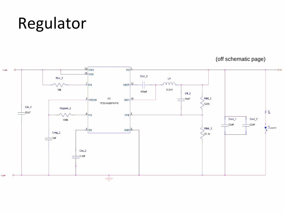
Regulator
(off schematic page)

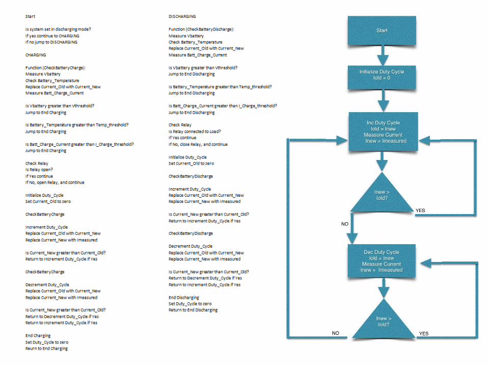
MPPT and Controls Flowchart

Electronics Test Plans
Connect system in normal operating configuration
Connect thermoelectric DAQ system to thermoelectric output for input voltage recording
Connect the DAQ to the I2C on the battery for output voltage recording
Connect the DAQ to the output of the Hall effect ammeter
Connect clamp meter around the positive lead of the thermoelectric
Synchronize all data acquisition systems
Check to ensure connectors are properly connect and working under safe conditions
Start recording data, and start heater, start charging by turning on regulator
Monitor data during charging periodically, and ensure still charging safely
Charge complete
Check state of charge, battery current, and battery voltage to ensure charging has stopped
Turn off heater, stop recording data, turn off regulator
Compile data, and calculate efficiency of power in and power out

Mechanical Design

CAD Modeling - Assembly
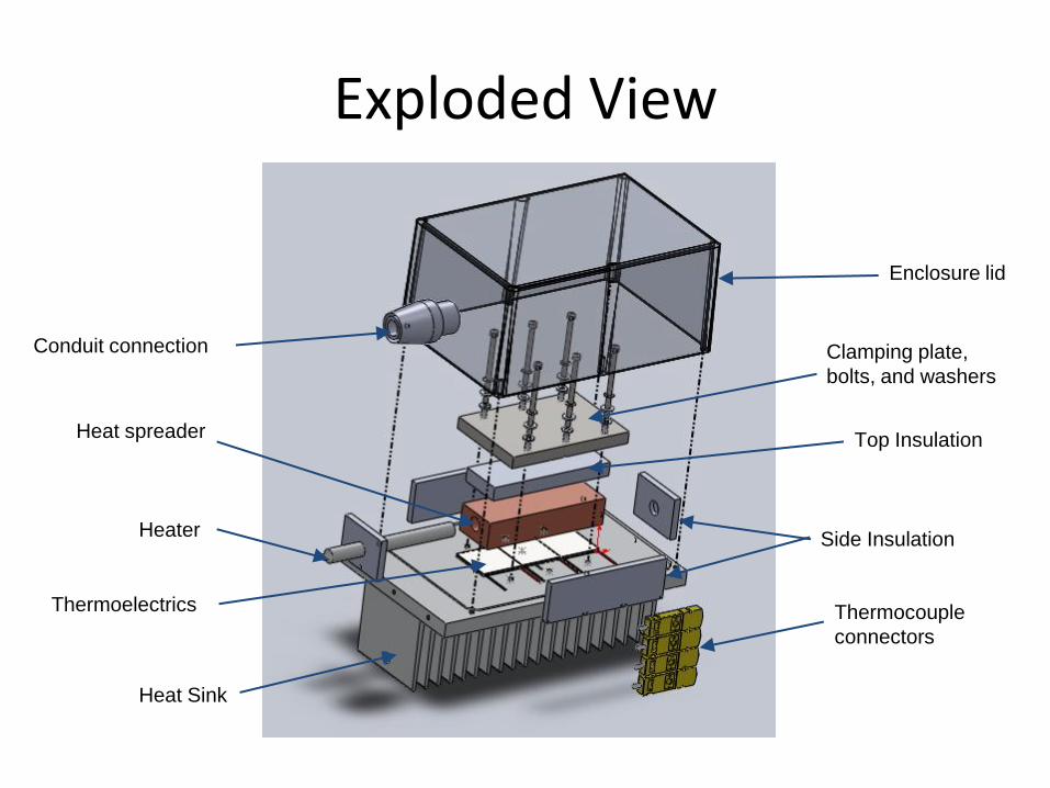
Exploded View
Clamping plate,
bolts, and washers
Top Insulation
Side Insulation
Thermocouple
connectors
Enclosure lid
Conduit connection
Heat spreader
Heater
Thermoelectrics
Heat Sink
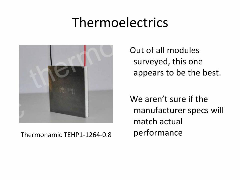
Thermoelectrics
Thermonamic TEHP1-1264-0.8
Out of all modules surveyed, this one appears to be the best.
We aren’t sure if the manufacturer specs will match actual performance
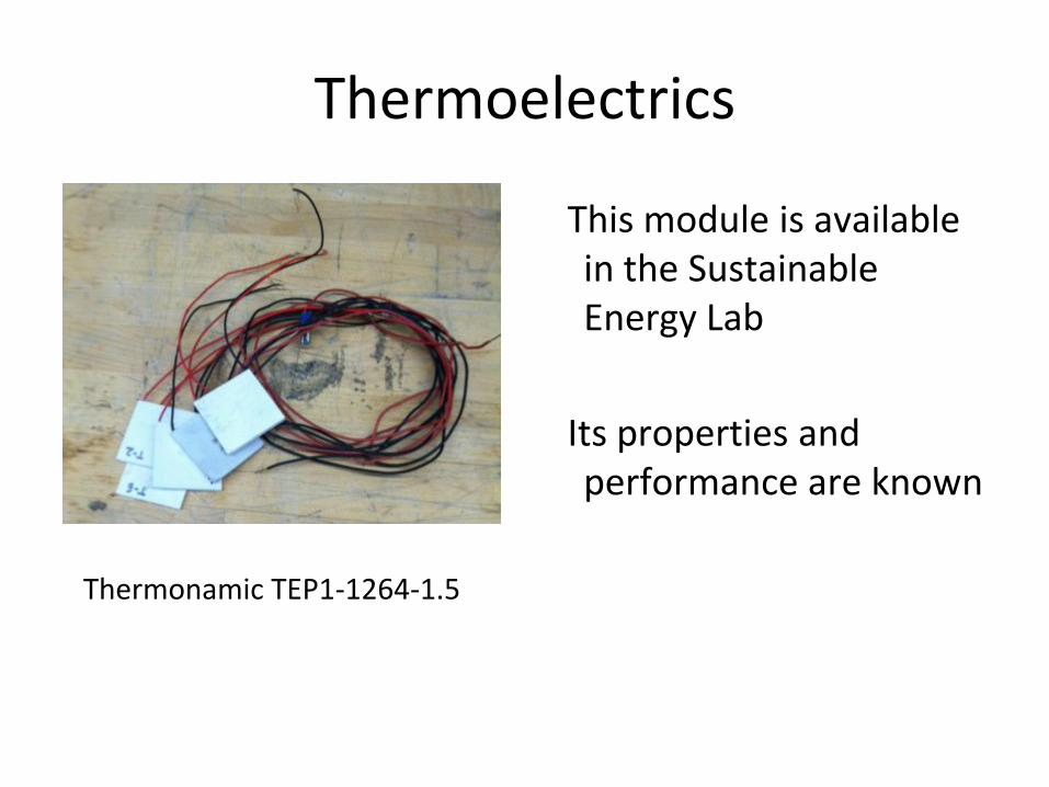
Thermoelectrics
Thermonamic TEP1-1264-1.5
This module is available in the Sustainable Energy Lab
Its properties and performance are known

Thermoelectrics
• Customer reqs were set assuming 4% efficiency. It is possible according to specs.
2x TEHP1-264-0.8 produce 18W with 450W in (4% efficiency)
Drawbacks: • MPPT must draw minimum current at all times.
• 2x TEP1-1246-1.5 would only produce 13W with 500W input.
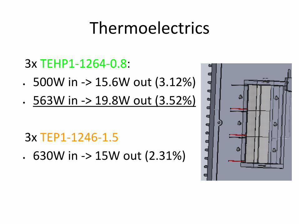
Thermoelectrics
3x TEHP1-1264-0.8:
• 500W in -> 15.6W out (3.12%)
• 563W in -> 19.8W out (3.52%)
3x TEP1-1246-1.5
• 630W in -> 15W out (2.31%)
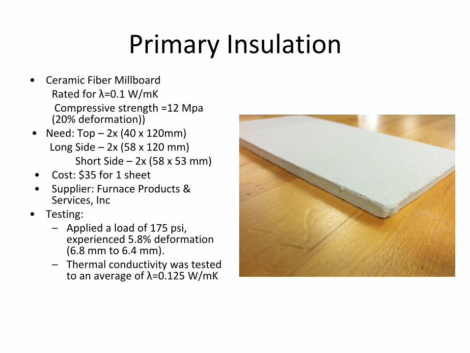
Primary Insulation • Ceramic Fiber Millboard
Rated for λ=0.1 W/mK Compressive strength =12 Mpa (20% deformation))
• Need: Top – 2x (40 x 120mm) Long Side – 2x (58 x 120 mm) Short Side – 2x (58 x 53 mm)
• Cost: $35 for 1 sheet • Supplier: Furnace Products &
Services, Inc • Testing:
– Applied a load of 175 psi, experienced 5.8% deformation (6.8 mm to 6.4 mm).
– Thermal conductivity was tested to an average of λ=0.125 W/mK
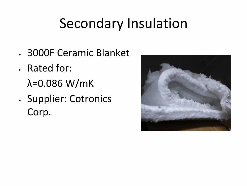
Secondary Insulation
• 3000F Ceramic Blanket
• Rated for:
λ=0.086 W/mK
• Supplier: Cotronics Corp.

Clamping Overview
TEMs, heating elements, and top primary insulation secured by bolting into baseplate

Clamping Analysis 110 psi of clamping pressure over TEMs:
• 90 psi preload, 20 psi thermal load
• 111 lbf preload per bolt, 25 lbf thermal load
• #8-32 NC 2A bolts yield an nf of 7.3
• EL = 0.13”
• Relative Thermal Expansion: 0.003”
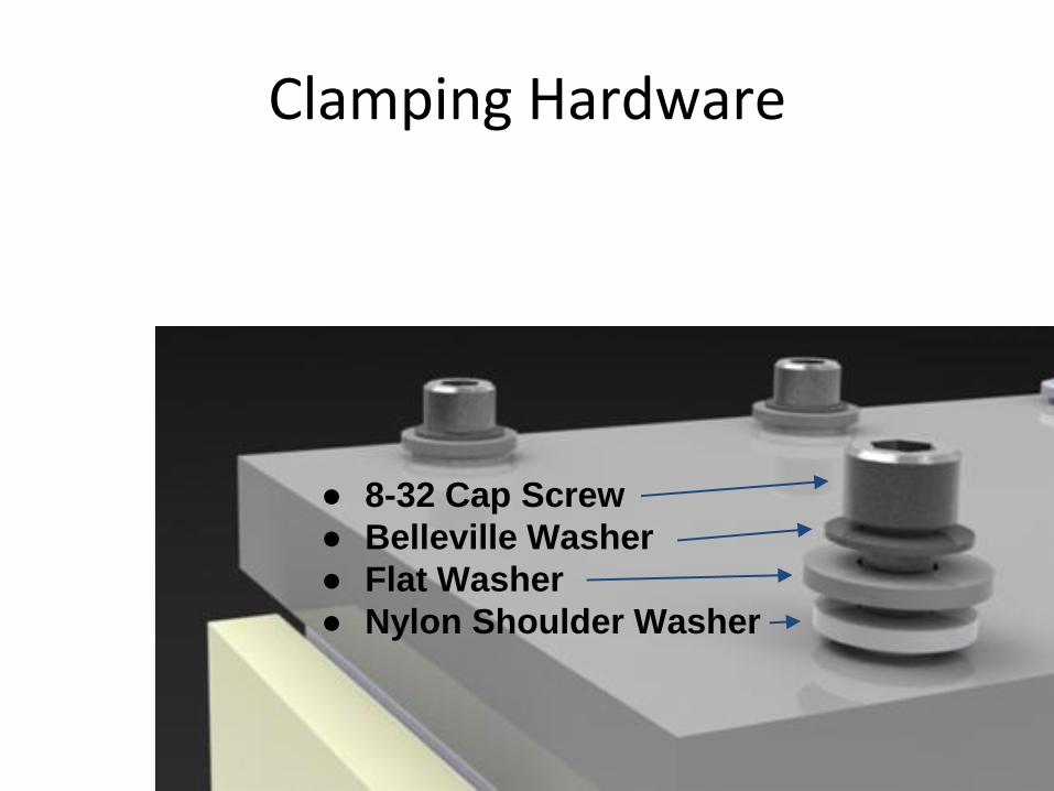
Clamping Hardware
● 8-32 Cap Screw
● Belleville Washer
● Flat Washer
● Nylon Shoulder Washer

Belleville Option • 3 Standard #8 Belleville Washers in parallel handle
both load and deflection.
• One heavy duty #8 Washer will handle load and deflection.

Bending Analysis
● 150 lbf loads applied to bolt holes
● Maximum deflection is 0.0002” -
This occurs in the pressure plate

Baseplate Bending
• Max deflection of 6.4 E-5” in baseplate
• This is less than the 0.001” specified by Custom Thermoelectric for acceptable mounting surfaces
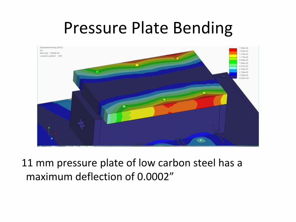
Pressure Plate Bending
11 mm pressure plate of low carbon steel has a maximum deflection of 0.0002”
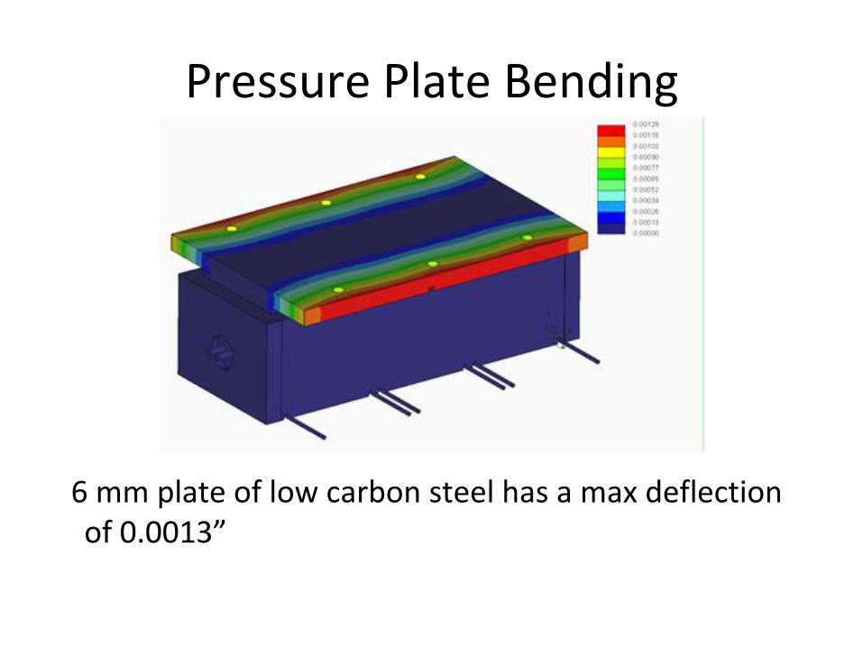
Pressure Plate Bending
6 mm plate of low carbon steel has a max deflection of 0.0013”

Clamping Assembly • Clean mounting surfaces using alcohol, lint free swab
• Add TEMs to baseplate, using etched lines to locate
• Add heat spreader and heater on top of TEMs with all sides flush
• Add clamping insulation to heat spreader
• Add Belleville and flat washers to bolts. Shoulder washers pressed into pressure plate.
● Insert bolts into pressure plate,
use bolt holes to locate pressure plate
● Finger tighten bolts one or two threads to ensure proper engagement
● Use torque wrench to tighten bolts to 4 in-lb in increments of 1 in-lb following figure
http://www.boltscience.com/pages/tsequence.htm

Enclosure
Deltron 480-0080
225x148x104 mm
~$46
• Comes with seal
• Sealing surface is simple
• Manufacturer provided CAD drawings
Therefore:
• we should be able to adapt it easily.
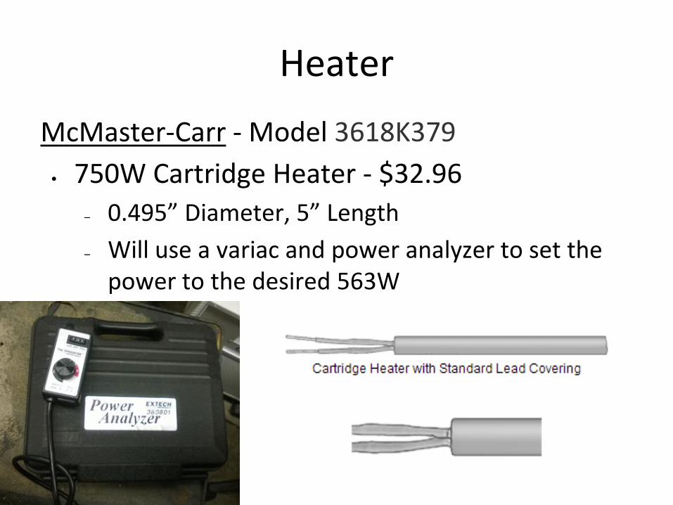
Heater
McMaster-Carr - Model 3618K379
• 750W Cartridge Heater - $32.96
– 0.495” Diameter, 5” Length
– Will use a variac and power analyzer to set the power to the desired 563W
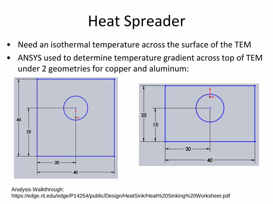
Heat Spreader
• Need an isothermal temperature across the surface of the TEM
• ANSYS used to determine temperature gradient across top of TEM under 2 geometries for copper and aluminum:
Analysis Walkthrough:
https://edge.rit.edu/edge/P14254/public/Design/HeatSink/Heat%20Sinking%20Worksheet.pdf
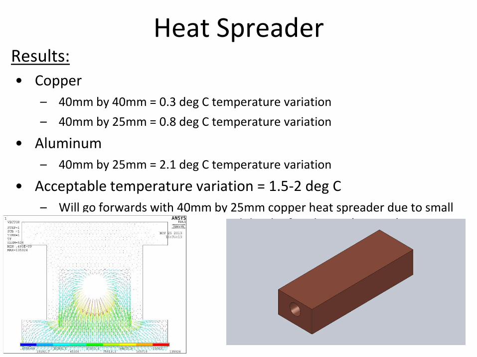
Heat Spreader Results:
• Copper
– 40mm by 40mm = 0.3 deg C temperature variation
– 40mm by 25mm = 0.8 deg C temperature variation
• Aluminum
– 40mm by 25mm = 2.1 deg C temperature variation
• Acceptable temperature variation = 1.5-2 deg C
– Will go forwards with 40mm by 25mm copper heat spreader due to small temperature variation and limited depth of enclosure (104mm)
Heat Sink
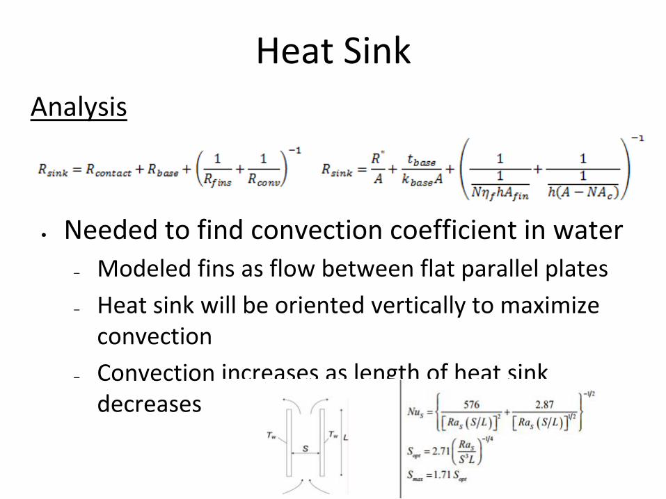
Analysis
• Needed to find convection coefficient in water
– Modeled fins as flow between flat parallel plates
– Heat sink will be oriented vertically to maximize convection
– Convection increases as length of heat sink decreases
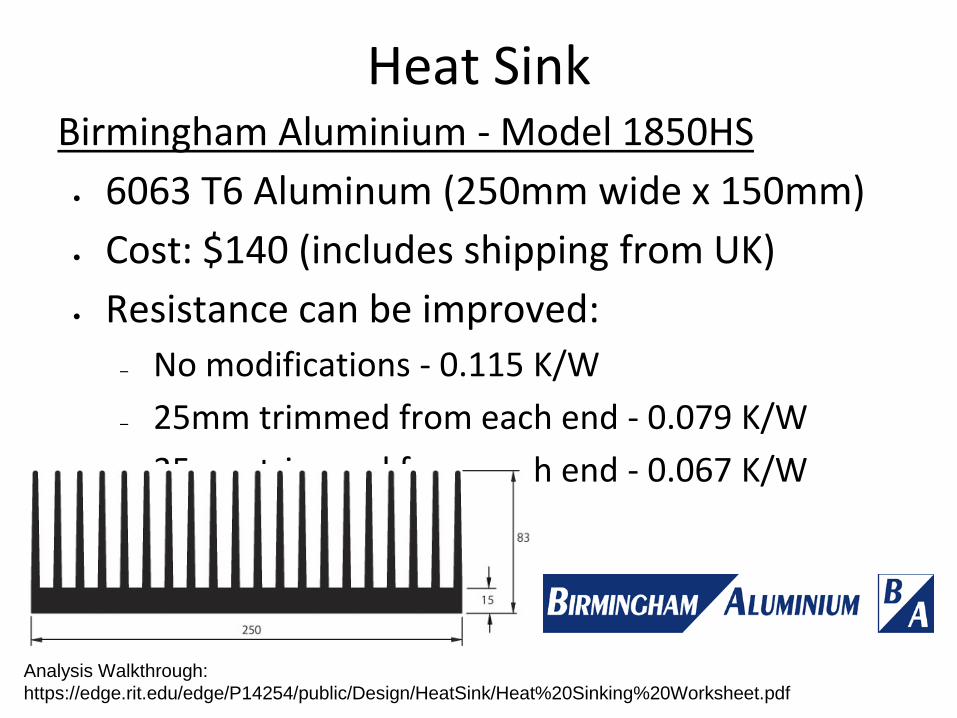
Heat Sink Birmingham Aluminium - Model 1850HS
• 6063 T6 Aluminum (250mm wide x 150mm)
• Cost: $140 (includes shipping from UK)
• Resistance can be improved:
– No modifications - 0.115 K/W
– 25mm trimmed from each end - 0.079 K/W
– 35mm trimmed from each end - 0.067 K/W
Analysis Walkthrough:
https://edge.rit.edu/edge/P14254/public/Design/HeatSink/Heat%20Sinking%20Worksheet.pdf

Heat Sink
Before Trimming
After Trimming

Cabling
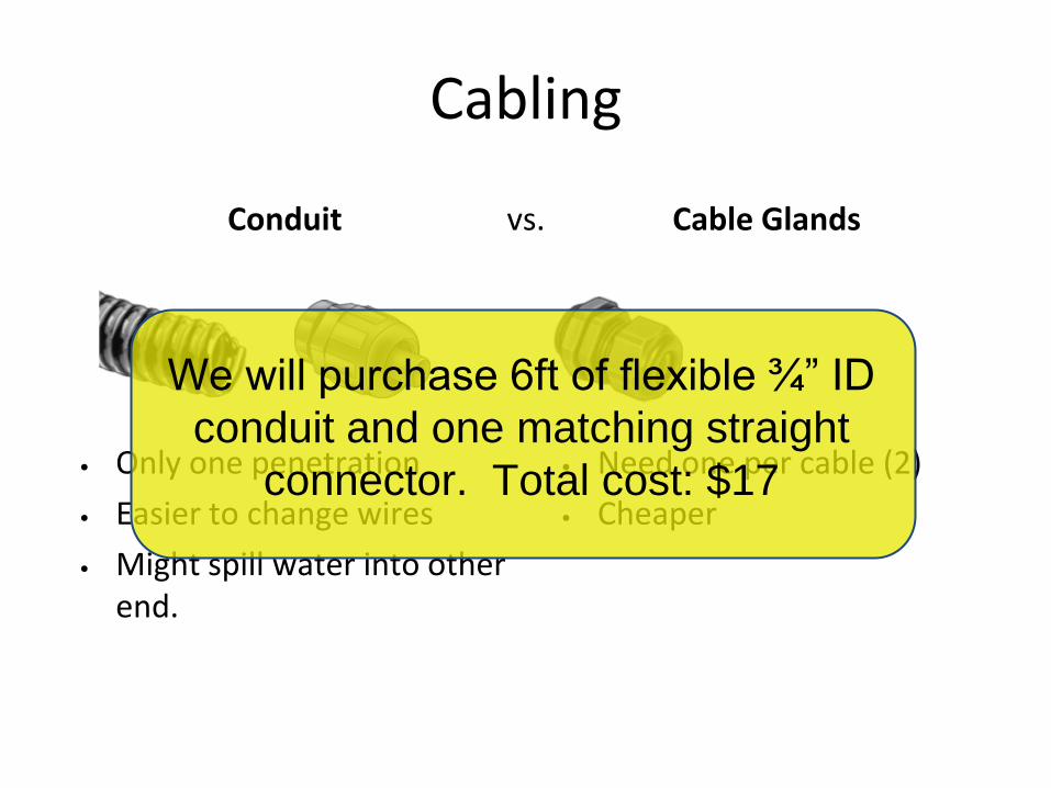
Conduit
• Only one penetration
• Easier to change wires
• Might spill water into other end.
Cable Glands
• Need one per cable (2)
• Cheaper
vs.

Cabling
Conduit
• Only one penetration
• Easier to change wires
• Might spill water into other end.
Cable Glands
• Need one per cable (2)
• Cheaper
vs.
Cabling
Conduit
• Only one penetration
• Easier to change wires
• Might spill water into other end.
Cable Glands
• Need one per cable (2)
• Cheaper
vs.
We will purchase 6ft of flexible ¾” ID
conduit and one matching straight
connector. Total cost: $17
Cabling
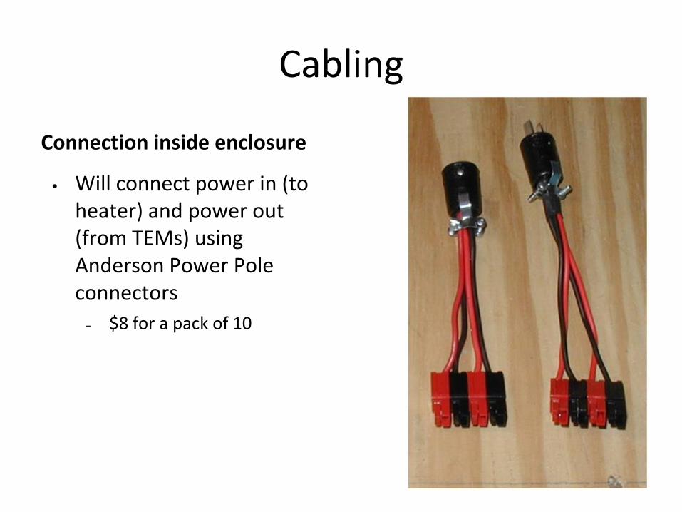
Connection inside enclosure
• Will connect power in (to heater) and power out (from TEMs) using Anderson Power Pole connectors
– $8 for a pack of 10
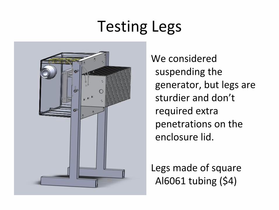
Testing Legs
The legs Reggie was talking about
We considered suspending the generator, but legs are sturdier and don’t required extra penetrations on the enclosure lid.
Legs made of square Al6061 tubing ($4)

Thermocouples
1. Hot Side
2. Cold Side
3. Clamping Plate
4. Ambient
Extension cable to carry signals.
$4.25/ft for 4 pair cable.

Test Tank
• Will ask FMS if we can borrow one
• If not, we can buy the 32 gallon trash can pictured left
– $18.99
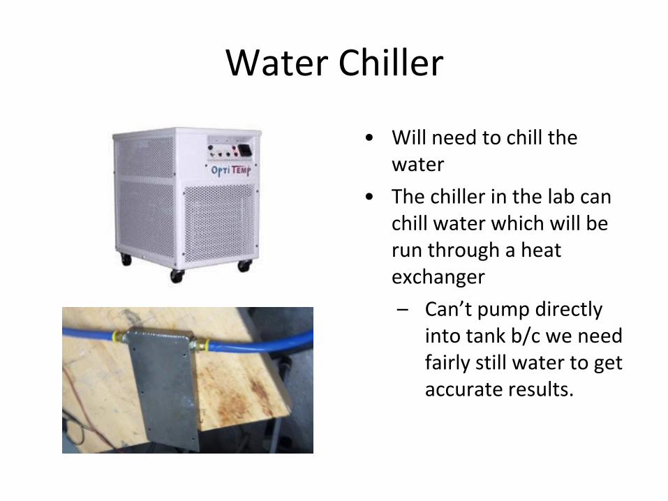
Water Chiller
• Will need to chill the water
• The chiller in the lab can chill water which will be run through a heat exchanger
– Can’t pump directly into tank b/c we need fairly still water to get accurate results.
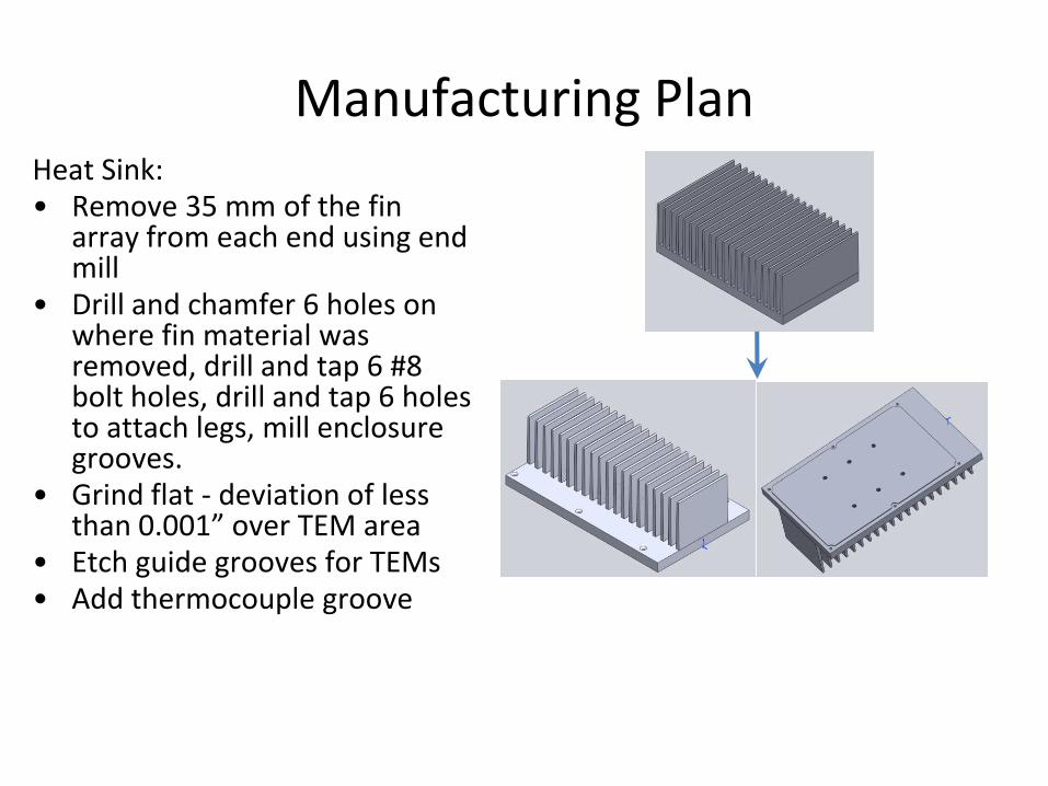
Manufacturing Plan Heat Sink: • Remove 35 mm of the fin
array from each end using end mill
• Drill and chamfer 6 holes on where fin material was removed, drill and tap 6 #8 bolt holes, drill and tap 6 holes to attach legs, mill enclosure grooves.
• Grind flat - deviation of less than 0.001” over TEM area
• Etch guide grooves for TEMs • Add thermocouple groove

Manufacturing Plan
Primary Insulation: • Cut ¼” sheet to specified
dimensions: Top – 2x (40 x 120mm) Long Side – 2x (58 x 120 mm) Short Side – 2x (58 x 53 mm) ● Cut hole in the short side
insulation for heater ● Cut grooves in long side
insulation for TEM wires
Manufacturing Plan
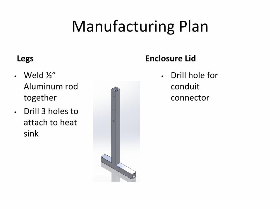
Legs
• Weld ½” Aluminum rod together
• Drill 3 holes to attach to heat sink
Enclosure Lid
• Drill hole for conduit connector

Mechanical Assembly Plan
1. Follow clamping subsystem assembly plan
2. Insert thermocouples and connect wiring
3. Install secondary insulation
4. Screw lid onto heatsink
5. Screw legs onto heatsink

Mechanical Test Plans
• Insulation
• Heat Sink
• TEMs
• Seals
• Clamping
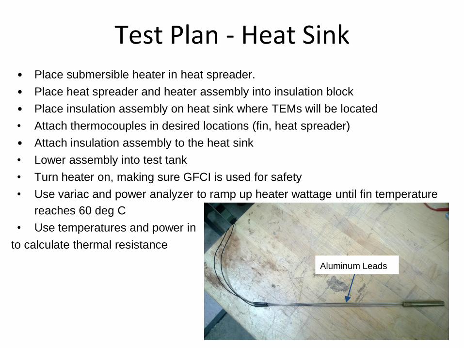
Test Plan - Heat Sink • Place submersible heater in heat spreader.
• Place heat spreader and heater assembly into insulation block
• Place insulation assembly on heat sink where TEMs will be located
• Attach thermocouples in desired locations (fin, heat spreader)
• Attach insulation assembly to the heat sink
• Lower assembly into test tank
• Turn heater on, making sure GFCI is used for safety
• Use variac and power analyzer to ramp up heater wattage until fin temperature
reaches 60 deg C
• Use temperatures and power in
to calculate thermal resistance
Aluminum Leads

Test Plan - Thermoelectrics
1. Apply thermal grease to cold side and install in thermoelectric test stand
2. Run test at 250C over 130C with open circuit condition
3. Check results against expected
4. Test at 180W over 60C with load at max power point.
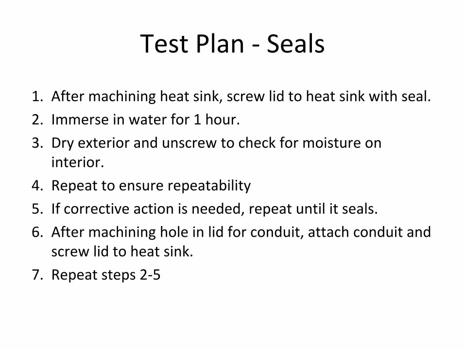
Test Plan - Seals
1. After machining heat sink, screw lid to heat sink with seal.
2. Immerse in water for 1 hour.
3. Dry exterior and unscrew to check for moisture on interior.
4. Repeat to ensure repeatability
5. If corrective action is needed, repeat until it seals.
6. After machining hole in lid for conduit, attach conduit and screw lid to heat sink.
7. Repeat steps 2-5

Test Plan - Clamping
• Clean mounting surfaces using alcohol, lint free swab
• Add pressure film to baseplate
• Add heat spreader and heater to pressure film
Following assembly plan:
• Add clamping insulation to heat spreader
• Add Belleville, flat, and shoulder washers to bolts
• Insert bolts into pressure plate, use bolt holes to locate pressure plate
• Tighten bolts with torque wrench
• Disassemble in reverse order
• Inspect pressure film to verify expected pressure
• Inspect threads and hardware for wear

Bill of Materials

Bill of Materials
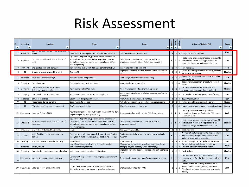
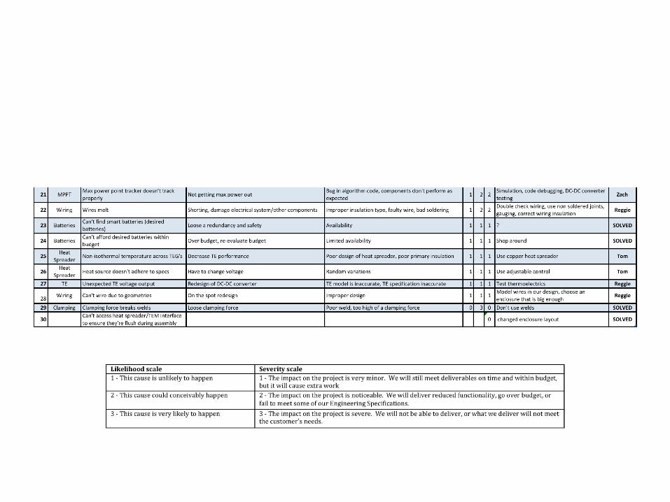
Risk Assessment

MSD II Project Plan


Questions?
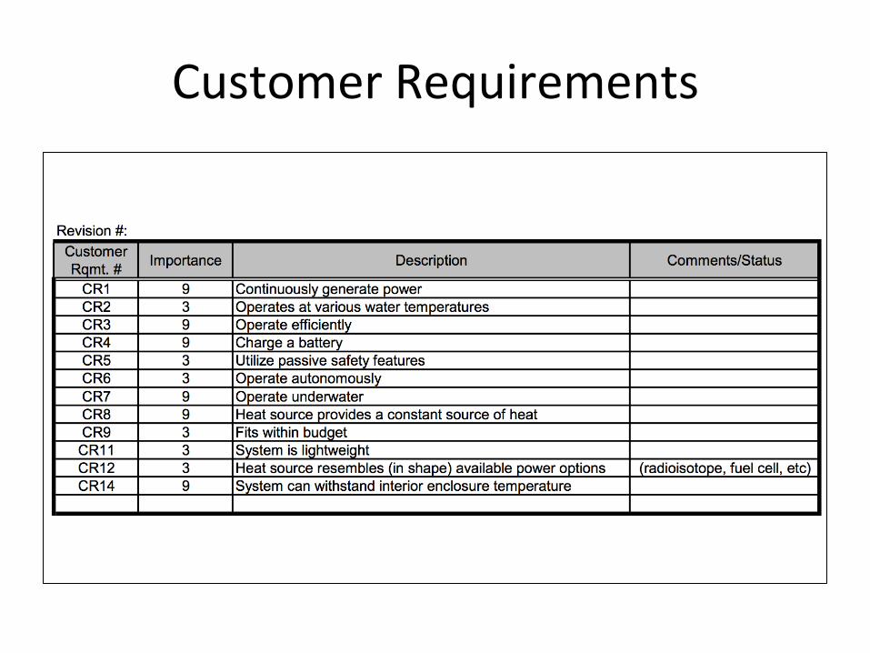
Customer Requirements
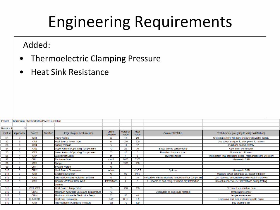
Engineering Requirements Added:
• Thermoelectric Clamping Pressure
• Heat Sink Resistance

Water sensor
https://www.sparkfun.com/products/12069
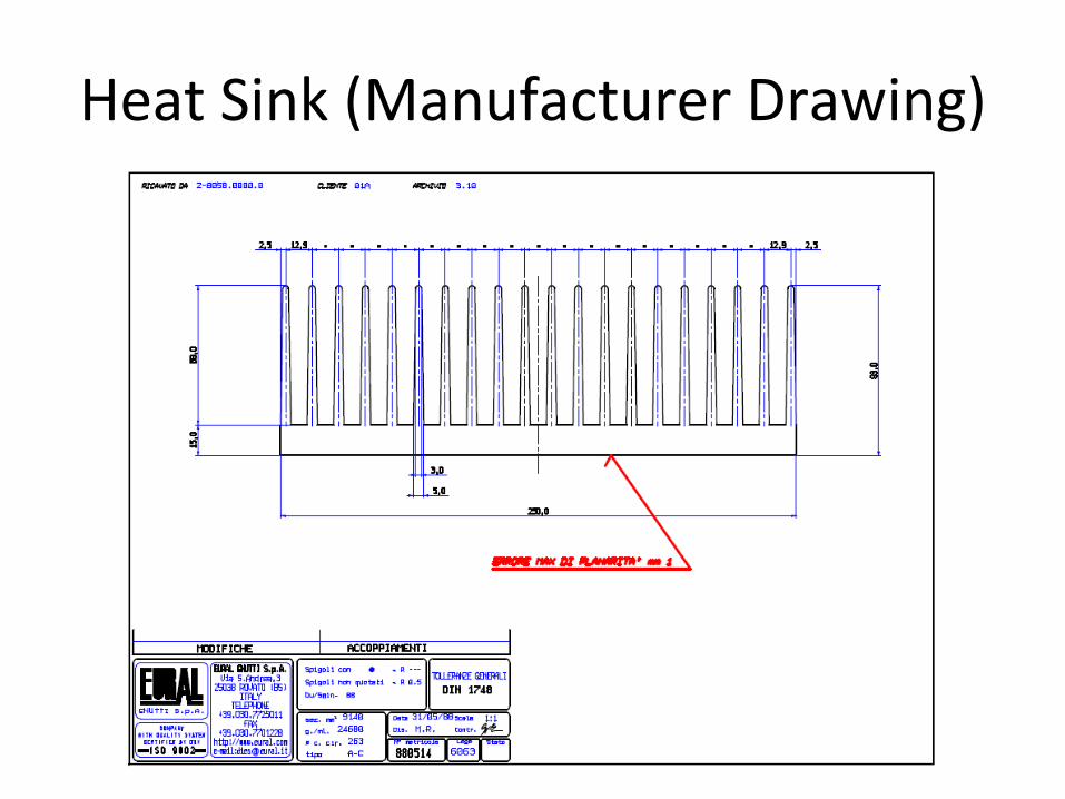
Heat Sink (Manufacturer Drawing)
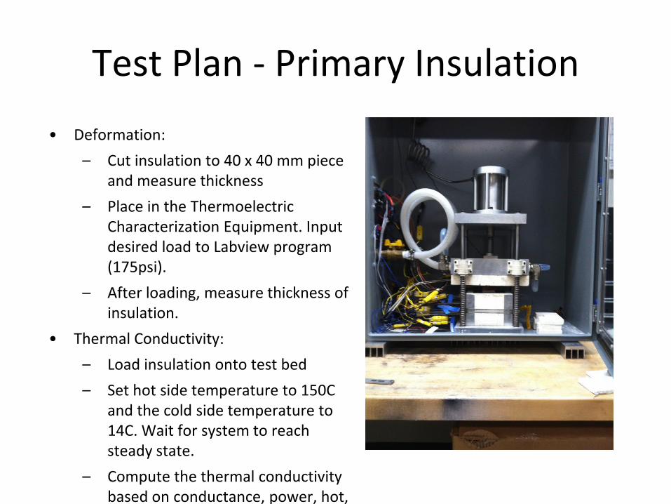
Test Plan - Primary Insulation
• Deformation:
– Cut insulation to 40 x 40 mm piece and measure thickness
– Place in the Thermoelectric Characterization Equipment. Input desired load to Labview program (175psi).
– After loading, measure thickness of insulation.
• Thermal Conductivity:
– Load insulation onto test bed
– Set hot side temperature to 150C and the cold side temperature to 14C. Wait for system to reach steady state.
– Compute the thermal conductivity based on conductance, power, hot, and cold side temperatures.

PC Board
Current Sensing: Resolution
• 10bit ADC ⇒ 4.5mV resolution
• 24bit ADC ⇒ 2.5uV resolution