p15242 autonomous people mover - edgeedge.rit.edu/content/p15242/public/documentation/golf cart...
TRANSCRIPT

USER’S
MANUAL P15242 Autonomous People Mover Rochester Institute of Technology December, 2015

1
Revision Sheet Release No. Date Revision Description Rev. 0 11/01/15 First draft of the user manual Rev. 1 12/10/15 Revised completely by Phase II team

2
User’s Manual
Authorization Memorandum
I have carefully assessed the User’s Manual for the Autonomous People Mover. This document has been completed in accordance with the requirements of the multidisciplinary team P16241 and Dr. Raymond Ptucha. MANAGEMENT CERTIFICATION - Please check the appropriate statement. ______ The document is accepted. ______ The document is accepted pending the changes noted. ______ The document is not accepted. We fully accept the changes as needed improvements and authorize initiation of work to proceed. Based on our authority and judgment, the continued operation of this system is authorized. _______________________________ _____________________ NAME DATE Dr. Raymond Ptucha _______________________________ _____________________ NAME DATE John Kaemmerlen _______________________________ _____________________ NAME DATE Joe Hudden _______________________________ _____________________ NAME DATE Michael Blachowicz

3
USER'S MANUAL
TABLE OF CONTENTS
Contents 1.0 GENERAL INFORMATION ........................................................................................................... 7
1.1 System Overview .......................................................................................................................... 7
1.2 Organization of the Manual .......................................................................................................... 7
1.3 Project References......................................................................................................................... 8
1.4 Acronyms and Abbreviations ........................................................................................................ 8
2.0 CONTROLS SUMMARY .............................................................................................................. 10
2.1 Subsystems Summary ................................................................................................................. 10
2.2 Braking ........................................................................................................................................ 10
2.2.1 High Level Overview .......................................................................................................... 10
2.2.2 Hardware ............................................................................................................................. 11
2.2.3 Software .............................................................................................................................. 13
2.2.4 Mounting ............................................................................................................................. 15
2.3 Throttle ........................................................................................................................................ 16
2.3.1 High Level Overview .......................................................................................................... 17
2.3.2 Hardware ............................................................................................................................. 17
2.3.3 Software .............................................................................................................................. 19
2.4 Steering ....................................................................................................................................... 21
2.4.1 High Level Overview .......................................................................................................... 21
2.4.2 Hardware ............................................................................................................................. 21
2.4.3 Software .............................................................................................................................. 23
2.5 Computer ..................................................................................................................................... 27
3.0 POWER SUMMARY ..................................................................................................................... 30
3.1 High Level Overview .................................................................................................................. 30
3.2 Hardware ..................................................................................................................................... 31
3.3 Mounting ..................................................................................................................................... 33
3.4 Power Analysis ........................................................................................................................... 33
4.0 SENSORS SUMMARY ................................................................................................................. 36
4.1 Subsystems Summary ................................................................................................................. 36
4.2 LIDAR ........................................................................................................................................ 36
4.2.1 High Level Overview .......................................................................................................... 36

4
4.2.2 Software .............................................................................................................................. 36
4.2.3 Wiring Diagram .................................................................................................................. 37
4.2.4 Mounting ............................................................................................................................. 38
4.3 Ultrasonic Sensors ...................................................................................................................... 38
4.3.1 High Level Overview .......................................................................................................... 38
4.3.2 Software .............................................................................................................................. 38
4.3.3 Wiring Diagram .................................................................................................................. 40
4.3.4 Mounting ............................................................................................................................. 40
4.4 Camera ........................................................................................................................................ 40
4.4.1 High Level Overview .......................................................................................................... 40
4.4.2 Software .............................................................................................................................. 41
4.4.3 Wiring Diagram .................................................................................................................. 41
4.4.4 Mounting ............................................................................................................................. 41
4.5 Encoders ...................................................................................................................................... 42
4.5.1 High Level Overview .......................................................................................................... 42
5.0 SOFTWARE SUMMARY ............................................................................................................. 44
5.1 Robot Operating System ............................................................................................................. 44
5.2 Navigation ................................................................................................................................... 45
5.2.1 High Level Overview .......................................................................................................... 45
5.2.2 Software .............................................................................................................................. 45
5.3 Controls ....................................................................................................................................... 46
5.3.1 High Level Overview .......................................................................................................... 46
5.3.2 Software .............................................................................................................................. 46
6.0 ELECTRICAL MODIFICATIONS SUMMARY .......................................................................... 50
6.1 PCB ............................................................................................................................................. 50
6.2 Arduino Shield ............................................................................................................................ 50
6.3 Enclosure ..................................................................................................................................... 50
6.3.1 High Level Overview .......................................................................................................... 50
6.3.2 Mounting ............................................................................................................................. 52
6.4 Dashboard ................................................................................................................................... 52
6.4.1 High Level Overview .......................................................................................................... 52
6.4.2 Wiring Diagram .................................................................................................................. 53
7.0 GETTING STARTED .................................................................................................................... 64
7.1 Starting the Golf Cart .................................................................................................................. 64

5
7.2 Calibrating ................................................................................................................................... 64
7.3 Using the GUI ............................................................................................................................. 64
8.0 REPORTING .................................................................................................................................. 66
8.1 Report Capabilities ...................................................................................................................... 66
8.2 Reports ........................................................................................................................................ 66

6
1.0 GENERAL INFORMATION

7
1.0 GENERAL INFORMATION Autonomous vehicles are currently being developed to improve roadway safety and optimize traffic flow. The Rochester Institute of Technology wishes to re-enter the field of autonomous driving by converting a low speed golf cart into an autonomous people mover. An autonomous people mover is a vehicle that transports people in a safe, fast, and comfortable way and requires no human interaction in normal operating circumstances. MSDII Team P15241 is currently working on a golf cart that will utilize remote control by the end of the 2015 spring semester. The scope of this project includes converting a remote controlled vehicle into a fully-autonomous vehicle capable of driving a course and avoiding basic obstacles. The safety of passengers and bystanders are the greatest concern, thus the vehicle will be programmed to drive conservatively. Both manual and remote control override will be available to intervene when needed.
1.1 System Overview The autonomous people mover has a few major subsystems. The first major subsystem is the control system. The controls subsystem uses both mechanical and electrical components in order to make the golf cart move. The subsystem has three main categories, braking, throttle, and steering. Power is the next major subsystem. There are two different batteries and voltage converters that are used in order to power all of the other systems on the golf cart. The third major subsystem is the sensors. The sensors are used to collect data to help determine the position of the golf cart. The main sensors that will be used for the golf cart are the LIDAR, ultrasonic, GPS, encoders, and the cameras. The next major subsystem is the software. All of the golf carts decision making, and data acquisition will be done using the Robot Operating System (ROS) and Arduinos. The last major subsystem is the electrical modifications. This includes the computer, PCB, Arduino shield, and the enclosure.
1.2 Organization of the Manual The user’s manual consists of eight sections: General Information, Controls Summary, Power Summary, Sensor Summary, Software Summary, Electrical Modification Summary, Getting Started, and Reporting. General Information section explains in general terms the system and the purpose for which it is intended. Controls summary section provides an overview of how each system works. The documentation needed to understand both the hardware and software components used. Power summary section provides an overview of how all of the electronics on the golf cart are getting powered. The documentation needed to understand what components are being used and how they are connected. Sensors summary section provides an overview of why each sensors was chosen and where they will be mounted. The documentation on how each sensor works. Software summary section provides an overview how the software works and the overall flow of the program. The documentation needed to understand all of the code that was written in ROS and Arduino.

8
Electrical modification summary section provides an overview for the electrical components inside the enclosure. The documentation needed to understand how all of the electrical components work and possible modifications for future phases. Getting started section explains how to get golf cart started and all of the calibration needed for the cart to work. The section presents how the GUI and other inputs of the golf cart are intended to be used. Reporting section describes what information was collected throughout the project.
1.3 Project References Golf Cart Documentation https://www.yamahagolfcar.com/download/2005/golf_car/2005_-_Golf_Cars_-_GMAX_Electric.pdf P15242 Edge Site http://edge.rit.edu/edge/P15242/public/Home GitLab Code Repository https://kgcoe-git.rit.edu/autonomous-golf-cart/golf-cart
1.4 Acronyms and Abbreviations PWM Pulse Width Modulation APM Autonomous People Mover ROS Robot Operating System

9
2.0 CONTROLS SUMMARY

10
2.0 CONTROLS SUMMARY Controls summary section provides an overview of how each system works. The documentation needed to understand both the hardware and software components used.
2.1 Subsystems Summary The system is comprised of three subsystems, braking, throttle and steering.
2.2 Braking To implement remote and autonomous braking an actuator was used to pull a steel cable that was connected to the brake pedal. Due to the size of the actuator it required a pulley to make a 90° turn before connecting to the brake pedal. The actuator and the pulley were mounted to the golf cart frame. This method allows for the passenger in the driver’s seat to still be able to hit the brake in an emergency situation. For feedback the internal potentiometer of the actuator was used as well as a magnetic field sensor. The braking system is controlled using a Sabertooth R/C Regenerative Dual Channel Motor Controller. This system requires a 12V input as well as a 1ms to 2ms-pulse width input signal provided by the designed control system. The potentiometer is used to control the position of the actuator and the magnetic sensor is used to sense if the passenger applies the brake so the golf cart can be stopped.
2.2.1 High Level Overview The high level overview gives a basic break down on how each signal is sent to all of the components of the braking system.

11
Braking System High Level Overview
2.2.2 Hardware The braking system was designed to allow the brakes to be used as originally designed without adding any additional risks of failure. This was done by running a steel cable through a hole drilled in the steel pedal, through the plastic divider “firewall”, around a pulley and to a high speed actuator mounted under the hood of the cart. The pulley has a sheet metal cover to prevent the cable from coming off when there is slack in the cable. The brake is also mounted with a small piece of foam which can activate a switch when the brake is pressed manually. The E150 linear actuator user manual can be found here and is pictured below.
E150 Linear Acuator
12
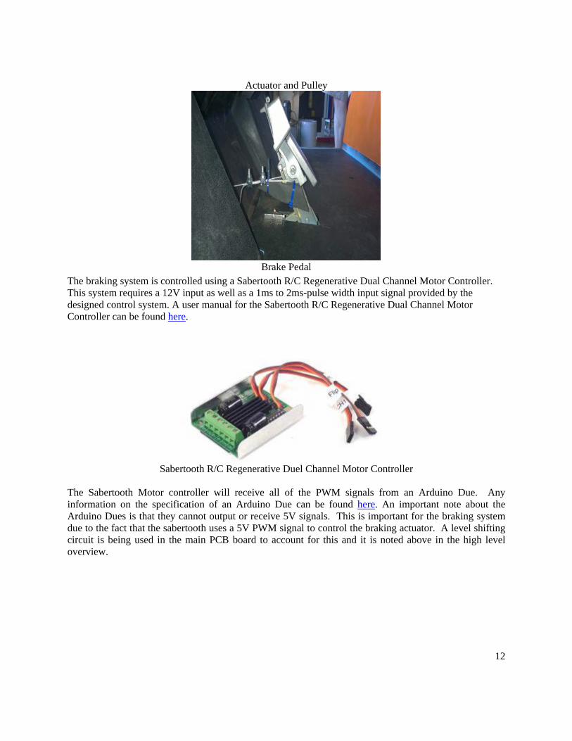
Actuator and Pulley
Brake Pedal
The braking system is controlled using a Sabertooth R/C Regenerative Dual Channel Motor Controller. This system requires a 12V input as well as a 1ms to 2ms-pulse width input signal provided by the designed control system. A user manual for the Sabertooth R/C Regenerative Dual Channel Motor Controller can be found here.
Sabertooth R/C Regenerative Duel Channel Motor Controller
The Sabertooth Motor controller will receive all of the PWM signals from an Arduino Due. Any information on the specification of an Arduino Due can be found here. An important note about the Arduino Dues is that they cannot output or receive 5V signals. This is important for the braking system due to the fact that the sabertooth uses a 5V PWM signal to control the braking actuator. A level shifting circuit is being used in the main PCB board to account for this and it is noted above in the high level overview.

13
Arduino Due
2.2.3 Software The software for the braking has been done two different ways. The first way to use the braking system is to bypass the PCB and just use the Sabertooth motor controller. The second is using the PCB and the level shifting circuits. The first program is shown below. This program bypasses the PCB and goes straight to the motor controller. Note that an Arduino Mega was used when testing this to get the required 5V output the motor controller needs. The servo.h library is used and can be found here. Below is from the sample code that was used to move the actuator.
The first line is used to include the servo.h library mentioned above. Doing this will allow one to work with all of the features that servo.h library provides. The Servo ST1 creates a servo object to control or in this case the actuator. The setup for this code is very simple, ST1 the servo object is then attached to pin 9 on the Arduino Mega. The Sabertooth accepts pulses from 1ms to 2ms so that time is set for pin 9 attached to pin 9 as well. The next step is the main code function, this can be seen below.

14
This is the void loop function in Arduino that means that this code will loop endlessly unless told otherwise. In this case there is nothing to break the loop. The ST1.write is used to set a value to send to the Sabertooth. A value of 0 is similar to 1ms PWM output. Sending a 1ms PWM will extends the braking actuator meaning the brake is set to the unused position. A value of 92 sends a 1.5ms PWM output signal which makes the actuator do nothing. When the actuator does nothing it means that it does not pull or extend. A value of 180 sends a 2ms PWM signal. This pulls the actuator along with the brake pedal. Below are examples of the expected output for each PWM signal.
PWM output to extent actuator

15
PWM output to do nothing
PWM output to pull the actuator
The second program works exactly the same as the first program with one exception. That being that to extend the brake a 1.2ms signal must be sent. This can be done by using a value of 20 degrees for the servo.h library instead of the 0 value given above.
2.2.4 Mounting Actuator mounting information can be found here.

16
Pulley Assembly Braking Actuator Front Alignment Mount
A flat bar welded to the main cross piece, positioned under the main pipe arm of the actuator A pipe clamp placed on it to provide non-load bearing alignment for the actuator
2.3 Throttle The throttle is currently not functioning properly through the PCB. If you bypass the PCB the throttle will work but not in manual mode.

17
2.3.1 High Level Overview The high level overview gives a basic break down on how each signal is sent to all of the components of the throttle system. The pedal and Arduinos uses a 0-3.3V signal to control the speed of the cart, where 3.3V is the top speed with the pedal. The Arduinos can go up to 5V it is unknown if the 5V will make the cart go faster than 12mph.
Throttle System High Level Overview
2.3.2 Hardware The golf cart motor is located in the back of the golf cart. This is the stock motor that comes with the Yamaha G22E golf cart. It is a JU2-H1890-10 Advanced D.C. Motors motor. It works at 48 Volts DC and it is has a class H rating. The motor has a rating of AU25000 3.5HP and a 2.6KWatt per 30 minutes.

18
Golf Cart Motor

19
For the throttle subsystem Arduino Dues are used in order to control the speed, for more information about the Due’s please refer to the documentation in the braking hardware section. The output used form the Dues are the DAC outputs. Both DAC outputs are used on the due, one is used as a reference voltage for the op amp circuit pictured below, and the other DAC is used to control the signal going to the ECU of the golf cart. A relay is currently in place to switch between remote mode and manual mode. The way the PCB is set up this will not work because when you tie the ground pin on the golf cart to the ground on the Arduino the solenoid will not stay on. The solenoid is needed to stay on or the throttle will not work. A fix to this could be using a relay for both pin 8 and pin 7 of the golf cart ECU to ensure the setup is working properly.
Op amp and relay circuit for throttle
2.3.3 Software The code for the PCB is yet to be determined due to the flaw in the way the PCB is made but to it should work nearly the same as the setup that doesn’t use the PCB. To switch on the AME relay the program that is used can be seen below. This uses the main Arduino board not the throttle board.
Code for AME relay
20
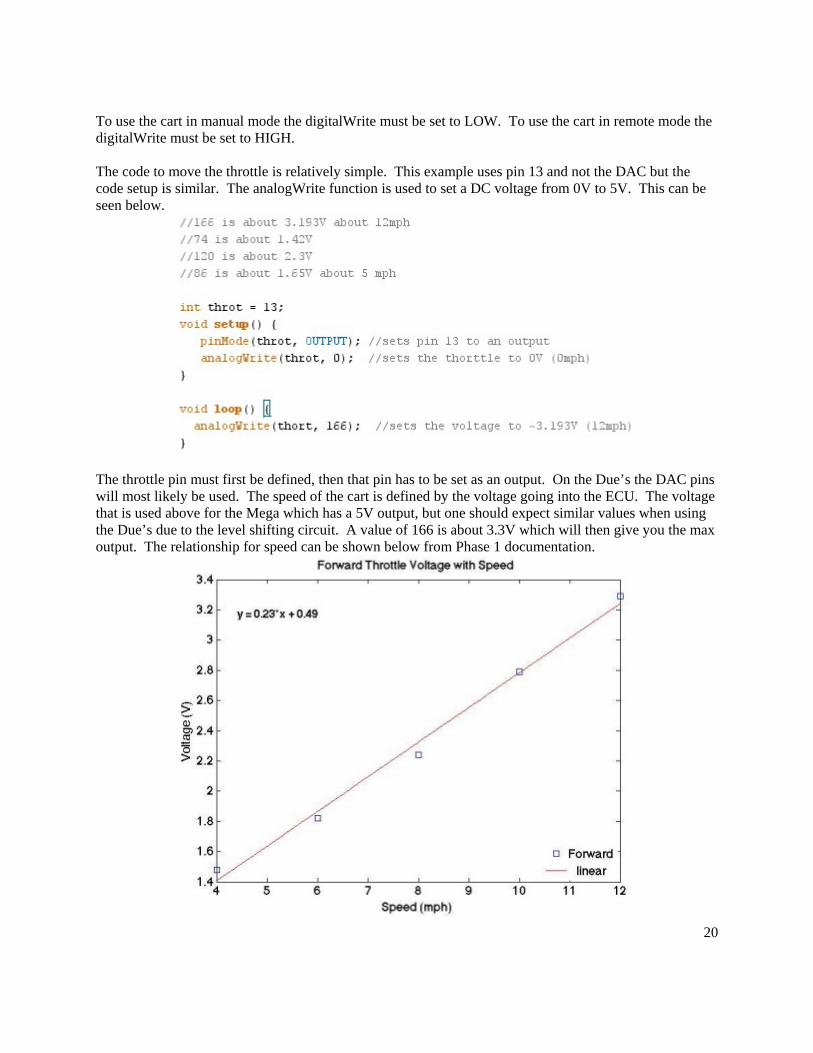
To use the cart in manual mode the digitalWrite must be set to LOW. To use the cart in remote mode the digitalWrite must be set to HIGH. The code to move the throttle is relatively simple. This example uses pin 13 and not the DAC but the code setup is similar. The analogWrite function is used to set a DC voltage from 0V to 5V. This can be seen below.
The throttle pin must first be defined, then that pin has to be set as an output. On the Due’s the DAC pins will most likely be used. The speed of the cart is defined by the voltage going into the ECU. The voltage that is used above for the Mega which has a 5V output, but one should expect similar values when using the Due’s due to the level shifting circuit. A value of 166 is about 3.3V which will then give you the max output. The relationship for speed can be shown below from Phase 1 documentation.

21
Voltage vs speed plot
2.4 Steering On a high level, explain the continuity of operations in the event of emergency, disaster, or accident. Explain what the effect of degraded performance will have on the user.
2.4.1 High Level Overview
2.4.2 Hardware The remote controller used on this project is the Spektrum DX6i. This remote controller is meant for RC planes. The user manual can be found here.

22
Spektrum DX6i
The receiver used for this project is the Spektrum AR610. The receiver gets 1ms to 2ms PWM signals from the controller. The receiver is pictured below with a description of what each output does. The output signals are 5V. Only one 5V input and one ground need to be plugged into power the receiver. All of the other wires just need to be the signal wire to the microcontroller.
THRO uses the left joystick and it controls the up/down motion AILE uses the right joystick and controls the left/right motion

23
ELEV uses the right joystick and it controls the up/down motion RUDD uses the left joystick and it controls the left/right motion GEAR uses the gear switch on the left side of controller and is an on/off switch AUX1 uses the flap/gyro switch near the left joystick and is an on/off switch
The hardware used for this electric power steering setup comes from Wickedbilt. Their UTV retrofit system utilizes 5V differential voltages to control motor torque and direction. Using the built in torque sensor and adding a chain driven potentiometer, steering shaft angle can be tracked at all times and torque can be managed via a PI feedback loop to achieve desired steering angles with appropriate amounts of smoothness.
2.4.3 Software The Phase I remote control code and the CE feedback loop code can both be found on GitLab. The work around for the PCB issue is below. The code for this uses the pulse in function with the Arduinos and can be seen below.

24
The pulseIn measurses a PWM signal and is then stored in the remo variable. The program can read in multiple values at once and is shown below.
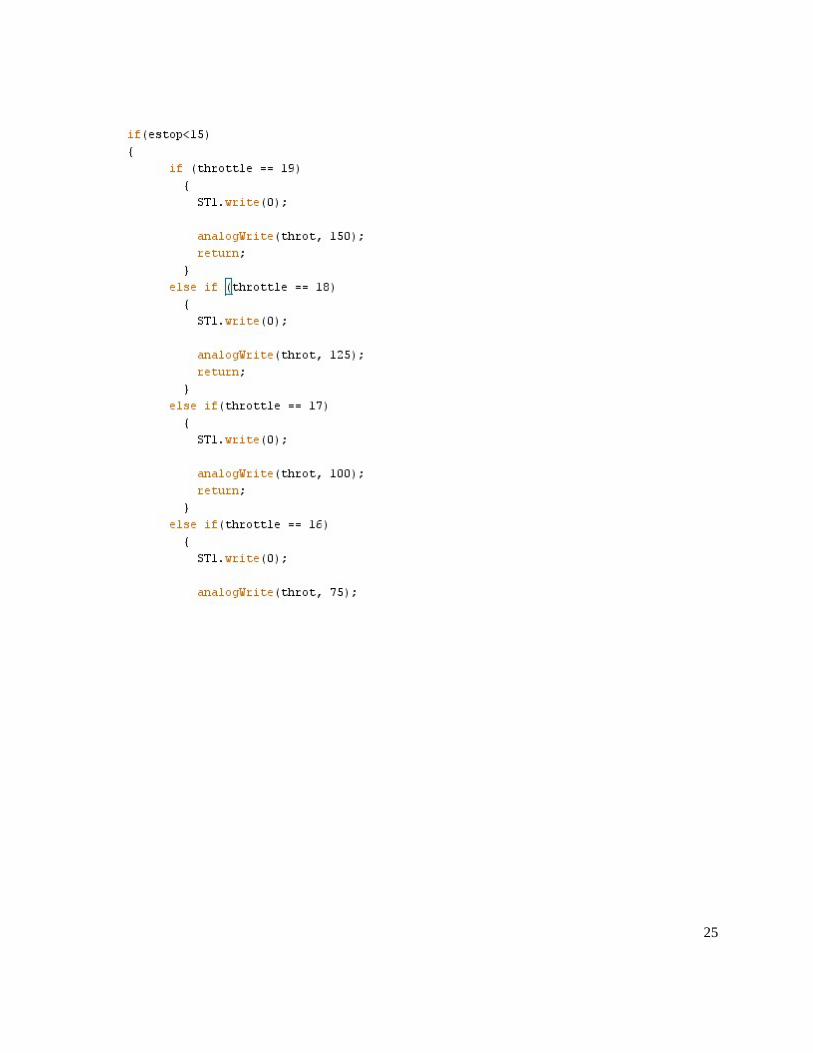
The signals are divided by 100 to reduce noise. An Estop was added to the throttle code and an example of all the code can be seen below. This just takes in the values of the Estop and decides if the estop signal is aqcuired the golf cart will then stop and the throttle will be cut. The majority of the code is a scaling factor for throttle making it vary in speed.
25

26
Smoother steering using PCB (Angel’s Code): In order to steer the cart, differential voltages must be applied to the steering system. Through the Steering Arduino board in the enclosure, DAC0 and DAC1 are used to write out the analog voltages. In particular, when DAC0 outputs a higher voltage than DAC1 the wheels will turn to the left and vice versa if DAC1 outputs a higher voltage instead. Note that a reference voltage must be set using DAC0 on the

27
Main Arduino for all the level shifters (a comment can be found in the CE feedback loop code regarding this matter). There are three testing programs developed to interact with the steering system. The first one, differential_steering.ino takes three inputs from the user, namely DAC0 voltage, DAC1 voltage, and desired wheel angle. The DAC voltages can be set from 0 to 5 volts while the angle range between -30 and 30 degrees. This program will enforce the specific differential voltages entered by the user and turn to the desired position. Once the desired position is reached, both DAC0 and DAC1 will be set to 0 to stop steering. PID_release.ino only takes the desired wheel angle as its input and use a PI control loop to steering to the correct position. The coefficients of the PI control needs to be further adjusted to be more effective. Similar to the previous program, PID_release.ino also sets DAC0 and DAC1 to 0 once the desired position is reached. Once done, a new input can be entered to continue the testing. Lastly, PID_hold.ino is a modification upon PID_release.ino. It differs from PID_release.ino by not resetting the differential voltages. Instead, it will hold the wheels at the desired steering location until the program is being reflashed to the board again. A MATLAB simulink model of the feedback loop can be found alongside these three testing programs as well. The model is not yet complete, more adjustments and additions may need to be added in the future, though this can serve as a foundation. With Robotics System Toolbox and Embedded Coder from MATLAB, the simulink model can either be exported directly as a ROS node or be exported externally to the Arduino board. Export process for these two cases can be easily found on MATLAB website.
2.5 Computer The golf cart contains a computer from the Computer Engineering department to function as a ROS host computer and provide processing power for computer vision. 2.5.1 Hardware
The computer has several components that are mounted on the cart, described below. Questions
about hardware can be directed to the Computer Engineering Lab Manager, Rick Tolleson ([email protected]).
● Motherboard - This is the main processing board on the computer, mounted in the upper
left of the enclosure. It is powered from the Computer PSU using a 4-pin CPU power cord and a 24-pin ATX power cord. It has connections to the SSD, LCD monitor, Arduinos, RIT internet, internal LAN, WiFi Adapter, and the power switch.
● LCD Monitor - This is the screen for the computer, mounted in the dashboard. More information is detailed in the Dashboard section. It connects to the motherboard with HDMI and USB
● Arduinos - The Arduinos connect to the motherboard through a USB hub on the back of the panel.
● SSD - The computer’s storage drive is a solid state drive mounted on the side of the enclosure. It is powered with a SATA power cable from the computer PSU and

28
communicated with a SATA data cable to the motherboard. ● RIT Internet - The motherboard has an onboard Ethernet connection next to the
headphone jacks that is configured to be connected to RIT’s internet exclusively. Inside Cube 2, there is one wall outlet with Ethernet jacks. It is configured to be plugged into the left jack on the wall.
● Internal LAN - An additional network card is present on the computer for communicating with the LIDAR and cameras on an internal LAN through a switch. This cannot be connected to the RIT internet, otherwise the bad will be let out. Don’t do it.
● Switch - This Ethernet switch connects the motherboard, LIDAR, and cameras together into one network so that they can communicate. The order in which Ethernet cables are connected to the switch is irrelevant. It is powered through a 12V supply
● Computer PSU - This PWR-M4-ATX power supply is a 250W 12V DC power supply for the computer, which converts the 12V input to several 12V, 5V, and 3.3V rails for the computer. It is powered on through the motherboard. For testing purposes, the power supply can be turned on by unplugging the 24-pin ATX power supply and jumping the green wire to ground. It provides a USB diagnostics tool for the motherboard, which connects to one of the USB headers on the board. Details about implementation can be found on MiniBox’s website.
● Power Button - The Computer Power button connects directly to the +PW- header pins on the motherboard. It provides the same wiring function as the power button on the front of a standard computer case.
● Wi-Fi - The WiFi adapter is connected to the motherboard via USB headers, and is mounted on the left of the enclosure.
2.5.2 Software
The computer runs Ubuntu 14.04 for an operating system. As the computer is a KGCOE lab computer, the system is supported by the system administrators. Contact the Computer Engineering systems administrator, Emilio Del Plato ([email protected]) for software support. If there is an issue with the system, the solution will usually be to reformat the computer and start fresh. This can be done by the system administrators. In this case, the computer will need to be reconfigured for the purposes of the cart. In the git repository, the Computer/Config file describes the various configuration and installation steps, as well as several pitfalls.

29
3.0 POWER SUMMARY

30
3.0 POWER SUMMARY The power system provides 12 volt, 5 volt, and 3.3 volt power to the electrical components on the cart. This is done by the use of various voltage converters and two different battery setups.
3.1 High Level Overview The cart is powered by a 48 Volt battery bank which is reduced to 12 Volt, 5 Volt, or 3.3 Volts as needed. Between the sensors and the desktop, 202 watts are required at 15 Volts, with the desktop requiring 145 watts. This works out to a current draw of 17.12 amps. The CUI Inc. VFK600 Series 48 Volt to 12 Volt DC-DC converter provides 50 amps at 12 Volts, more than enough to run the existing equipment with room to expand in the future. The cart’s 48 Volt battery bank is estimated to have a battery life of 1.57 hours, or 94 minutes under normal use with the current selection of sensors and compute power. Live wires have red insulation exclusively; ground wires have black insulation exclusively. Green insulation is used for the connection from the power system to the cart ground. The 12 volt battery is used to power the braking actuator and the steering.
High Level Overview of Power System

31
3.2 Hardware
Golf Cart Batteries
http://www.digikey.com/product-detail/en/PYB20-Q24-S3-U/102-3246-ND/4477504

32
http://www.digikey.com/product-detail/en/PYB30-Q24-S5-U/102-3262-ND/4477520 http://www.cui.com/product/resource/pyb20-u.pdf
http://www.digikey.com/product-detail/en/VFK600-D48-S12/102-2463-ND/2770681
Terminal blocks, 4 inputs, 16 outputs – 2 inputs go to the top 8 outputs, 2 inputs go to the bottom 8 outputs. Top row is used for 12 volt, bottom row is used for ground.

33
3.3 Mounting The image below shows the mounting location of the 12V battery under the seat of the golf cart. It is resting between the two main chassis rails on a piece of 1/4in thick aluminum plate. Four holes at the corners of the plate are used by four 3in pipe clamps. To remove the likelihood of longitudinal movement of the 12V Battery, four pieces of aluminum scrap were epoxied to the rails in front of and behind the two forward clamps. Combined with the mass of the battery, these enable the battery tray to remain very secure.
3.4 Power Analysis The table below is how to determine the minimum battery life of the cart. You take each device that is added to the cart and determine the quantity to be added. Then find the maximum power draw multiply by quantity and that becomes the total power. Divide total power by the rated voltage to find the current draw at maximum load. Sum all this together to get the ideal maximum current draw. The converter has an efficiency of 0.9 so divide the maximum current draw by 0.9 to get the actual current draw. Multiply actual current draw by 1000 to get amps to milliamp hours. Add milliamp hours to the previous milliamp hour total and divide into 75000 to get the battery life in hours.
Device Quantity Power Total Power
Voltage Amps
Camera 2 7 W 14 W 12 V 1.167 A Lidar 1 12 W 12 W 12 V 1 A Ultrasonic 3 .5 W 1.5 W 5 V .3 A Micro 1 1.5 W 1.5 W 5 V .3 A Desktop 1 145 W 145 W 12 V 12.083 A Screen 1 10 W 10 W 12 V .833 A Ethernet Switch
1 14.4 W 14.4 W 12 V 1.2 A
Fan 2 2 W 4 W 12 V .333 A Ideal current draw 17.217 A
Current draw w/ efficiency 19.130 A Phase 2 additions 19129.63
mAh Total 47784.63
mAh Battery life at full draw 1.570 hours

34

35
4.0 SENSORS SUMMARY

36
4.0 SENSORS SUMMARY
4.1 Subsystems Summary The sensors included in this project to date are the Velodyne VLP-16 ‘Puck’ LiDAR unit, the Hikvision IP Bullet cameras, and the MaxBotix outdoor waterproof ultrasonic sensors. These sensors have been tested independently of the APM control systems and have not yet been installed on the APM or integrated with the APM systems.
4.2 LIDAR The LiDAR module used was the 16 channel VLP-16 module by Velodyne, referenced at: http://velodynelidar.com/vlp-16.html.
4.2.1 High Level Overview The LiDAR module was used to read in point cloud data around the surrounding of the vehicle. The resolution of the device allows for the ability to obtain visual odometry information and object information for both tracking cart movement and detecting obstacles in the environment.
4.2.2 Software The LiDAR raw data can be observed using the VeloView software that was provided with the module, independent from ROS. Additionally, a ROS package exists to capture the LiDAR output and feed it into ROS as a topic that publishes PointCloud2 data. The primary tool used to visualise the LiDAR point cloud data was the RVIZ visualizer in ROS. Using the ROS formatted PointCloud2 data, a number of packages exist to utilize the LiDAR data. The Velodyne ROS node is responsible for starting up the PointCloud2 topic in ROS. This topic is called “velodyne_points” and can be started using the cart.launch launch file located in the repository.
37
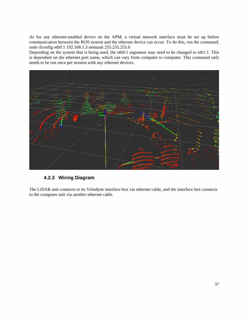
As for any ethernet-enabled device on the APM, a virtual network interface must be set up before communication between the ROS system and the ethernet device can occur. To do this, run the command, sudo ifconfig eth0:1 192.168.1.3 netmask 255.255.255.0 Depending on the system that is being used, the eth0:1 argument may need to be changed to eth1:1. This is dependent on the ethernet port name, which can vary from computer to computer. This command only needs to be run once per session with any ethernet devices.
4.2.3 Wiring Diagram The LiDAR unit connects to its Velodyne interface box via ethernet cable, and the interface box connects to the computer unit via another ethernet cable.

38
4.2.4 Mounting There is no mounting of the LiDAR unit as of yet. Sample designs of mounts have been produced though none are in production or use.
4.3 Ultrasonic Sensors The ultrasonics acquired for the APM were MaxBotix MB7001 long range weather resistant sensors.
4.3.1 High Level Overview The ultrasonic sensors were acquired for this project as an additional fail-safe system to the LiDAR unit. As they have not been mounted or integrated into the systems of the APM as of yet, the code was designed for receiving and processing the data signals for future use by the system.
4.3.2 Software Two ROS nodes have been implemented for Arduino microcontrollers to read and publish information from the ultrasonic sensors to ROS topics. The first publishes raw ultrasonics data as a float message and the second populates and publishes a laser scan message. See section 5.4.1 for details on how to implement ROS nodes on Arduino microcontrollers. The ROS node that publishes raw ultrasonics data can be found on the GitLab repository under Arduino/us_sensor/us_sensor_ros/us_sensor_ros.ino. The Arduino ROS node simply reads the analog signal from the port where the ultrasonic sensor is connected and publishes that data on its ROS topic.

39
The second ROS node populates a ROS LaserScan message and can be found on the GitLab repository under Arduino/us_sensor/us_sensor_ros_2_laserscan/us_sensor_ros_2_laserscan.ino. The Arduino code initializes a ROS LaserScan message in the setup loop, filling in certain constants and header information:
The frame_id is a generic string that identifies the frame that the LaserScan data can be viewed in (via RVIZ, etc.). The fields angle_min and angle_max are the start and end angles (in radians) of the scan. The fields angle_increment and time_increment are the angular distance (radians) and time (seconds) between measurements. The field scan_time is the time (seconds) between scans. The fields range_min and range_max are the minimum and maximum range values (meters) that can be read. The field ranges_length is the number of elements that are in the ranges field array (how Arduino initializes arrays). In the loop function:
The ultrasonics raw data is read from the analog port and the time the value was read is saved to the header.stamp field (necessary for ROS messages with timing information). The value of the analog signal is converted to meters before being capped at the minimum and maximum range values.
An array is then populated with the ultrasonics data (same distance for the whole range).
The ranges field array is then set to the new ranges information before being published to the ROS topic.

40
4.3.3 Wiring Diagram
4.3.4 Mounting There is no mounting implemented for the ultrasonics as of yet. Preliminary plans included using the threads on the back of the ultrasonics to mount them to the front bumper of the golf cart.
4.4 Camera Development of ROS nodes for the Hikvision IP cameras was started, but as of now, work still exists to complete them.
4.4.1 High Level Overview Two Hikvision Bullet cameras with IR capability stream video information to the ROS system via Python or C++ nodes developed specifically for the cameras.

41
4.4.2 Software Two versions of the camera nodes exist: one in Python, and one in C++. As of now, the C++ version of the node produces segmentation faults when reading in a frame of the video stream. More analysis should be done to determine the exact reason for the error, but it seems to be an issue with memory allocation in the Mat type of OpenCV. The error has only been reproducible on the Hikvision cameras. Upon using a lower resolution webcam, the node seems to stream video properly. As for any ethernet-enabled device on the APM, a virtual network interface must be set up before communication between the ROS system and the ethernet device can occur. To do this, run the command, sudo ifconfig eth0:1 192.168.1.3 netmask 255.255.255.0 Depending on the system that is being used, the eth0:1 argument may need to be changed to eth1:1. This is dependent on the ethernet port name, which can vary from computer to computer. This command only needs to be run once per session with any ethernet devices. The Python node is able to stream the video data from the camera to a topic called /apm_hikvision_py_<number>, where <number> is the last octet of the camera IP address. For a camera with an IP address of 192.168.1.101, the topic name would be /apm_hikvision_py_101. To use a camera node, first add the apm_cameras package to the ROS workspace, and then run catkin_make. Source the setup script to reflect the changed workspace (source devel/setup.bash), and then the camera nodes can be started with the command,
rosrun apm_cameras apm_py_cameras_node.py <number> where <number> is again, the last octet of the camera IP address. This process will also create a node called /apm_hikvision_py_node_<number>. Although the camera node provides the video stream from the camera, in its current state, the video distorts if there is minimal movement between consecutive frames of the video, which will impact object detection from color images if not addressed. The issue is reproducible if the camera is left still for more than 10 seconds, focused on the same location. However, once the camera moves, the distortion ceases and clear video is streamed again. Line by line documentation is provided in line with the node code for each language version of the node in the apm_cameras package.
4.4.3 Wiring Diagram The Hikvision Bullet cameras connect directly to an available ethernet port on the computer or on an ethernet switch.
4.4.4 Mounting There is no mounting implemented for the cameras as of yet. Preliminary designs included a level base that would sit upon the cart’s roof frame. The centers of the camera bases would be 100mm apart, an idea distance for performing stereo vision. The base consists of three pieces; the angular base, the base plate, and the camera bases.

42
4.5 Encoders
4.5.1 High Level Overview The brake encoder is not operational. The Speed encoder signal enters the system on Pin 14 (NOT 16) of the 23-pin connector. It is a 5V square wave signal with 50% duty cycle. The frequency of the square wave is directly proportional to the frequency, with off being 0Hz and full throttle being around 210Hz. The sensor is directly connected to the wheel speed, presumably a Hall Effect Sensor. The steering encoder is a potentiometer connected to the steering column. The slider of the potentiometer is connected to the control PCB in the back of the cart.

43
5.0 SOFTWARE SUMMARY

44
5.0 SOFTWARE SUMMARY The software system on the APM utilizes a ROS communication system to implement controls and data processing.
5.1 Robot Operating System Robot Operating System (ROS) was used to implement the data processing for the sensors in addition to the controls on the Arduino microcontrollers. ROS nodes executed operations based on changes in the data in the ROS topics. ROS Topics serve as communication channels upon which messages can be sent. Messages can either be standard scalar values (Integers, Floats, Bools, Empty messages, etc), or custom messages which contain multiple types. Each topic is named in a hierarchical format, relative to the /golfcart root topic (such that you can have a topic named /golfcart/example/topic). The topics used in the control system are described in git in ROS/golfcart/Topics.txt, copied below: /golfcart - /mode -> String (MANUAL, REMOTE, AUTO) - Sent from the Computer or Arduino when the mode is changed - /running -> bool - Whether or not the auto mode should run - /main - /status -> msg/main_status.msg - Reports on the main board status (e.g. e-stop) - /want_cal -> Empty - Sent from the Arduino to request the calibration values - /load_cal -> msg/main_set_cal.msg - Loads calibration values onto the Arduino - /store_cal -> msg/main_set_cal.msg - Stores calibration values on the computer - /throttle - /status -> msg/throttle_status.msg - Reports on the throttle board status (e.g. vtach, brake actuator) - /control -> uint8 - Sent from the computer with the throttle value as a percentage. - /want_cal -> Empty - Sent from the Arduino to request the calibration values - /load_cal -> msg/throttle_set_cal.msg - Loads calibration values onto the Arduino - /store_cal -> msg/throttle_set_cal.msg - Stores calibration values on the computer - /steering

45
- /status -> msg/steering_status.msg - Reports on the steering board status (e.g. angle) - /control -> int16 - Sent from the computer with the desired steering angle (left = negative, right = positive) - /want_cal -> Empty - Sent from the Arduino to request the calibration values - /load_cal -> msg/steering_set_cal.msg - Loads calibration values onto the Arduino - /store_cal -> msg/steering_set_cal.msg - Stores calibration values on the computer - /braking - /control -> uint8 - Sent from the computer with the brake position as a percentage - /start_calibration - Empty - Sent from the computer as a signal to start the calibration sequence - /end_calibration - Empty - Sent from the computer when all calibration signals received This lists the hierarchical topic structure used, along with the expected message type and the description of what it is used for. The message files are stored in ROS/golfcart/msg, and various scripts (such as the GUIs) are stored in ROS/golfcart/scripts.
5.2 Navigation
5.2.1 High Level Overview The navigation in ROS is based off of the Navigation Stack documented at: http://wiki.ros.org/navigation. The navigation stack defines the necessary steps required to achieve full autonomy. The standard coordinate conventions used in this project are explinaned in depth at: http://wiki.ros.org/geometry/CoordinateFrameConventions. Several additional ROS packages were pulled into the project for the navigation including the following:
- GMapping (http://wiki.ros.org/gmapping) - Laser Scan Matcher (http://wiki.ros.org/laser_scan_matcher) - PointCloud to LaserScan (http://wiki.ros.org/pointcloud_to_laserscan) - Move Base (http://wiki.ros.org/move_base)
5.2.2 Software The navigation for the cart can be started using the cart launch file. This launch file sets up the necessary transforms and launches the associated nodes. The concept of transforms and the TF tree necessary for using many of the navigation packages can be found at: http://wiki.ros.org/tf. After the transforms, the nodes for each of the mentioned ROS packages are launched, with several parameters specified within each node. An in depth explanation of each parameter for each included package can be found online. The pointcloud_to_laserscan node is responsible for condensing the pointcloud2 data into a 2D laser scan representation to be used in the laser scan matcher. Parameters can be specified to alter the vertical and horizontal points captured and condensed.

46
The laserscan matcher node is responsible for matching previous laser frames to current laser frames to estimate the pose of the cart using visual odometry. Many parameters exist to change the sensitivity of matching, altering the poses produced. The GMapping node is responsible for constructing a visual map of the vehicle's surroundings and also contains numerous parameters affecting the rate of generation, the minimum and maximum points considered, and the sensitivity of matching. The apm_odometry node was constructed to be able to produce odometry navigation messages to be used in future navigation. The source code for this node is documented in the source file. This node subscribes to the estimated pose data produced from the scan matcher and adds a default constant velocity of 0.1m/s to generate a somewhat accurate odometry navigation message called “odom”. Future work on this node should replace the constant velocity model with accurate velocity estimates to produce accurate odometry navigation messages and transforms.
5.3 Controls Controls in ROS were implemented on Arduino microcontrollers which required some additions to the Arduino code and additional steps in the setup of the ROS system. A tutorial for setting up the system can be found at http://wiki.ros.org/rosserial_arduino/Tutorials/Arduino%20IDE%20Setup.
5.3.1 High Level Overview Implementing ROS nodes on Arduino Microcontrollers requires some additions to the Arduino code. The following two lines must appear at the beginning of any Arduino ROS code file before any other code or comments:
A tutorial for publishing or subscribing to ROS topics from an Arduino ROS node can be found at the websites below: http://wiki.ros.org/rosserial_arduino/Tutorials/Hello%20World http://wiki.ros.org/rosserial_arduino/Tutorials/Blink
5.3.2 Software Some samples for ROS nodes that implement control systems have been written and uploaded on the GitLab repository. However these ROS nodes have not been tested on the Golf Cart system as of yet. The main Arduino board has two sample ROS nodes located in the GitLab repository under: Arduino/control_main/control_main.ino and Arduino/control_main2/control_main2.ino.

47
The former is a ROS node implementation of the Phase I code for controlling the golf cart systems which de-prioritizes calibration and makes calibrating the systems with the remote controller voluntary. The latter implementation uses a package to implement the ROS node as a state machine, however this code is only a skeleton code and does not contain any controls functionality for the APM. The steering and the braking/throttle Arduino boards also have two sample ROS nodes located in the GitLab repository. The steering code can be found under: Arduino/control_steering/control_steering.ino and Arduino/control_steering2/control_steering2.ino. Like the main board code, the former is a ROS node of the Phase I code and the latter is the state machine skeleton code of a ROS node. The braking throttle code can be found under: Arduino/control_throttle/control_throttle.ino and Arduino/control_throttle2/control_throttle2.ino. Again, the former is a ROS node of the Phase I code and the latter is the state machine skeleton code of a ROS node. The APM state machine is designed as follows:
The finite state machine package that was used to implement the state machines on the APM were included using the following line of code:
The following states and machine are set as global variables:

48
The parameters to the States are the entry function, the update function, and the exit function associated with that state. The entry function is executed once upon entering that state. The exit function is executed once upon exiting that state (presumably before the next state’s entry function). The update function executes when called. A state machine is initialized in the setup function:
The update function is called in the loop function:
State transitions are handled using the following command:
FSM.transitionTo will change the current state of the state machine to the state indicated. FSM.isInState returns a boolean indicating whether the current state of the state machine is the indicated state.

49
6.0 ELECTRICAL MODIFICATIONS SUMMARY

50
6.0 ELECTRICAL MODIFICATIONS SUMMARY
6.1 PCB Most of the relays on the PCB are not used, with the exception of the Auto/Manual relays for throttle/steering. The level shifting circuits are the only things that are truly necessary. Level shifting is not necessary for the throttle, it is needed for steering and brake. The purpose of the PCB is to pass signals to/from the automotive connectors to the DB25 connectors.
6.2 Arduino Shield The shield mounting standoff points should be on the shield board itself rather than using the Arduinos’ to mount to the electrical panel. The shield works but the LEDs are unused so could be redesigned for a better purpose.
6.3 Enclosure
6.3.1 High Level Overview The enclosure is located on the back of the cart. To take the panel off, the fans need to be removed. To remove the fans make sure that the power to both fans is disconnected (wires TB03+ and TB03- and wires labeled R Fan) from the panel, the hard drive, HDMI, USB, LED lights, WiFi adapter, wires labeled TB01+ and TB01- need to be disconnected. After these are all disconnected remove the four nuts and washers holding the PCB panel in place. Then carefully pull the PCB panel straight out a little way until just off the bolts. Once the PCB panel is off the bolts, tilt the top of the PCB panel toward yourself. There are wires with quick connects on the bottom backside of the panel that need to be disconnected. After all these wires are disconnected, the panel can be carefully removed from the enclosure. All wires and connections to and from the cart come into the enclosure through the larger hole at the bottom right of the enclosure. To remove the enclosure from the cart, all connections coming from the cart into the panel, must be disconnected. Then all the mounting bolts must be removed.

51
The three mounting bolts can be seen above as 1, 2, and 3. The upper bolts (1, 2) go through the inside holes of the two tabs.
Top down view: How to place washers and nuts on bolts.

52
6.3.2 Mounting The primary mounting elements for the enclosure are the two full thread ¼ in bolts through the flanges at the top of the enclosure and the enclosure base at the bottom. The upper bolts should be used with a lock washer and standard washers on the front face. Bolts should be torqued to ~8lb-ft. The enclosure base is secured with two full thread 5/16 in bolts. The upper bolt is secured from the top with a lock nut, goes through the lower plate of the enclosure, and threads into the upper section of the enclosure base. The lower bolt is secured from the bottom with a lock nut, goes through the lower frame rail of the golf cart, and threads into the bottom of the enclosure base. When installing the enclosure base start by loosening the two upper bolts. Always secure the bottom bolt first making sure the lock nut is threaded all the way to the head of the bolt. To make fitment of the upper bolt easiest, torque the bottom bolt to ~12lb-ft to ensure the base is flush against the rear tray. Once torqued swing the bottom of the enclosure forward carefully to align the top of the enclosure base and the hole in the bottom of the enclosure. Once aligned thread the lock nut all the way to the head of the bolt, insert the upper bolt, and torque to ~12lb-ft. (Specs: 1/2in thick threaded aluminum plate at each end, 2.7in long 1x1in aluminum square stock center section)
(Upper) (Lower)
6.4 Dashboard
6.4.1 High Level Overview The Dashboard consists of wiring and switches/buttons required for the operator to interact with the control systems. The switches included in the dashboard are: a 10.1” LCD Touchscreen, an emergency-stop switch, a Visible/Audible Alert switch, a Forward/Reverse switch, the golf cart power key, and the accelerator stop toggle switch. The operation of the components is detailed below:
● LCD Touchscreen - This touchscreen communicates with the processing computer via HDMI and USB, with HDMI providing video signal to the monitor and USB providing touch inputs to the computer. The LCD has a status LED which changes color based on the status: Red when the monitor is powered off, Orange when it is powered on but there is no video input, and Green when it has video input. The LCD is powered by a 12V power supply, which is fed from the 48V converter in the rear of the cart.

53
● Emergency Stop Switch - The switch is used by a passenger to stop the cart in an emergency. It contains three contact blocks, used to provide two stop functions. Two are used to switch a GPIO input to the Arduino from +3.3V to GND when the button is pressed, which is used to notify the control software and causes the brake to be pressed and the throttle to be cut. A third contact block is used to cut the physical throttle signal wire going into the golf cart controller, ensuring a fail-safe method to prevent the cart from losing control. BTW, this shit doesn’t work.
○ When the E-Stop button is pressed, the following should occur: ■ Cut the Throttle physically from the golf cart ■ Switch to Manual mode ■ Activate the brake ■ Stop the control system.
○ When the E-Stop button is released, the following should occur: ■ Re-connect the throttle signal ■ Remain in Manual mode ■ Release the brake
● Visible/Audible Alert Switch - The golf cart has both visible and audible alerts present. A three position On-Off-On rocker switch is used to switch which alerts are being used. The middle position is everything off. Switching one direction enables both the visible strobe light on the top of the cart and the audible beeping alert. Switching the other direction enables only the strobe light.
● Forward/Reverse switch - This is a switch that switches the direction the cart is moving. This is a stock switch included on the standard golf cart.
● Key - This turns on the cart, which must be done for the throttle to drive. It does not switch the 48V input to the enclosure, nor does it switch the 12V power for the brake and steering systems.
● Accelerator Stop Toggle Switch - This toggle switch replaces the switch inside the accelerator pedal. On the stock golf cart, a switch is present in the accelerator pedal to prevent the cart from moving unless the pedal is physically pressed, and to ensure that the cart does not move if the pedal is pressed while the key is turned on. This button replaces this switch to enable driving autonomously without pressing the pedal. The button must be deactivated (out) when the cart is turned on, and then must be pressed in order to drive. A click and a humming should be heard when the cart is successfully activated.
The dashboard is not waterproof, and thus the golf cart should not be driven outside in the rain. In order for the dashboard to be waterproof, a new mounting solution will be required to prevent the LCD from getting wet and to protect the electronics inside.
6.4.2 Wiring Diagram

PAGE 1: MAIN POWER
PAGE 1A: 12V SUPPLY GOLF CART MOTOR
PAGE 2: ELECTRICAL CABINET
PAGE 2A: BRAKE/WICKED RELAYS
PAGE 2B: AMP SEAL HEADERS
PAGE 3: PLASTIC TUBING COVERED ELECTRIC HARNESSES
PAGE 3A: PLASTIC TUBING COVERED ELECTRICAL HARNESSES/MUTLI-WIRE CABLES
PAGE 4: BRAKE ACTUATOR/ WICKED STEERING/ LCD/ MISC. FRONT CONNECTIONS
TABLE OF CONTENTS:
54

-+
12V
12V
12V
12V
12V
12V
BATTERY BANK
CHARGER OUTLET
+
+
+ -
+-
- +
- +
- +
- +
+
-POS
NEGA2
A1
F1 F2
+
-
GOLF CART CONTROLLER
LOCATION: Under Seat/Back of CartDRAWING DESCRIPTION: Main Power
TO GOLF CART MOTOR
TO +48V DC-DC
TO CONTROLLER 23-PIN AMP SEAL HEADER
SOLENOID CONNECTOR
TO 48-12V DC-DC
TO GOLF CART 23-PIN
AMP SEAL HEADER
55
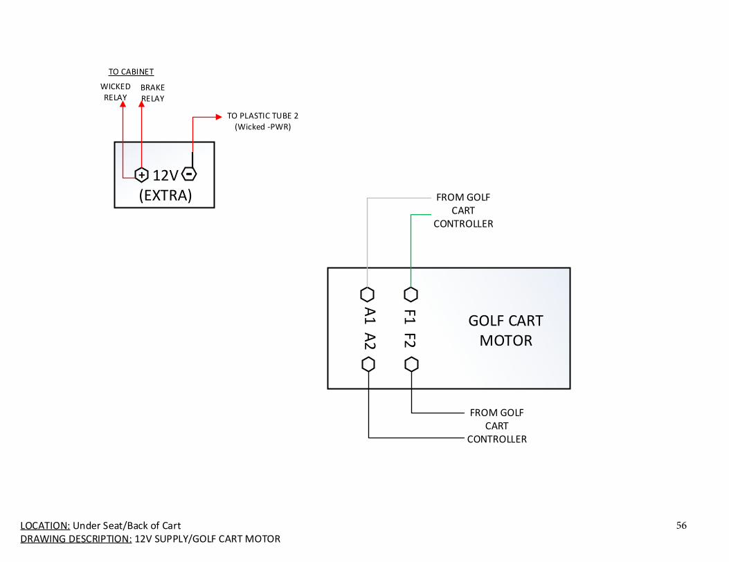
LOCATION: Under Seat/Back of CartDRAWING DESCRIPTION: 12V SUPPLY/GOLF CART MOTOR
12V(EXTRA)
-+
TO PLASTIC TUBE 2 (Wicked -PWR)
TO CABINET
BRAKE RELAY
WICKED RELAY
GOLF CART MOTOR
F1 F2
A1
A2
FROM GOLF CART
CONTROLLER
FROM GOLF CART
CONTROLLER
56

LOCATION: Back of CartDRAWING DESCRIPTION: ELECTRICAL CABINET
COMPUTER 48V DISCONNECT
BRAKE/STEERING
POWERPOWER
COMPUTER WICKED
ISSUEBRAKE ACTUATOR
SABERTOOTH
FANFA
N
ETH
ERN
ET S
WIT
CH
ARDUINO SHIELD
MAIN PCB
TB(REAR)48V-12VDC-DC
5V 3VCOMPUTER PWR
FAN
DRI
VE
USB
USB
HDMI
DB-25DB-25
DB-25DB-25
TO CONTROLLER 23-PIN AMP SEAL HEADER
(same as on page 1A)
TO GOLF CART 23-PIN AMP SEAL
HEADER
TO DASHBOARD & SENSORS 35-PIN AMP SEAL
HEADER
Ard
uin
o D
UE
Ard
uin
o D
UE
Ard
uin
o D
UE
Micro USB
Micro USB
Micro USB
TO FRONT
OF CART
USBHUB
x3
x3
+++
+++
++
+++
+++
++
+Vin
CASE
-Vin
+Vo+Vo+SPC
TRIM-S
-Vo-Vo
+++ +
P2 P2 P1 P1
CASE GND
+++ + +++ +
+++ + +++ +
NC
Trim 0V
+Vo
Vin
G
ND
Ctr
l Ca
se
GN
DV
inCt
rl
Case
NC
+Vo
Trim 0V
+++ + +++ + +
+++ + +++ + +
08
07
06
05
04
03
02
01
P2
08
07
06
05
04
03
02
01
P1
+++
PWRGND
PWRGND
LED
PWRGND
GN
D
PWR
To TB01-
To T
B01
+
FROM 48V Disconnect
FROM Golf Cart Controller A2
+++
3.3VGND5V
KEY: = Behind Board/Panel = Given Electrical Harnesses = Behind and Given Electrical Harness
ETHE
RNET
ETHER NET
Co
mp
. PCB
Cab
le
FROM Rear Solenoid
TO +48V DC-DC
CPU_FA N
WIF
I An
tenn
a
F_US B2 F_US B1PW
Dri
ve
Pow
er
Seri
al A
TA
Serial ATA
AT
X_1
2V
S2S15V0V
+++
+
M1AM1BB+B-M2AM2B
++
S1S2
TO Brake/Wicked Coil
LED
PWRGND
FROM TB (REAR) P1 T7
RED To Br ake/Wicked
Power Switch BLK To
Wicked /Br ake Coils
(behind)
FROM Brake RelayFROM -12V Extra Battery
TO Plastic Covered Tube 2
57

LOCATION: Back of CartDRAWING DESCRIPTION: ELECTRICAL CABINET RELAYS
BRAKE RELAY
`
WICKED RELAY
TO WICKED +PWR
TO B+ (SABERTOOTH)
FROM +12V EXTRA BATTERY
FROM POWER SWITCH
FROM TB (REAR) P2 T7
58

LOCATION: Back of CartDRAWING DESCRIPTION: AMP SEAL HEADERS
PIN1PIN2PIN3PIN4PIN5PIN6PIN7PIN8PIN9
PIN10PIN11PIN12PIN13PIN14PIN15PIN16PIN17PIN18PIN19PIN20PIN21PIN22PIN23
AM
P SE
AL
23-P
IN H
EA
DER
AMP1AMP2AMP3AMP4AMP5AMP6THROT_OUTTHROT_GNDTHROT_PWR_OUTAMP10AMP11AMP12AMP13THROT_VTACHAMP15AMP16AMP17AMP18AMP19AMP20AMP21AMP22AMP23
TO CONTROLLER
PIN1PIN2PIN3PIN4PIN5PIN6PIN7PIN8PIN9
PIN10PIN11PIN12PIN13PIN14PIN15PIN16PIN17PIN18PIN19PIN20PIN21PIN22PIN23
AM
P S
EAL
23-P
IN H
EAD
ER
AMP1AMP2AMP3AMP4AMP5AMP6THROT_INTHROT_GNDTHROT_PWR_INAMP10AMP11AMP12AMP13THROT_VTACHAMP15AMP16AMP17AMP18AMP19AMP20AMP21AMP22AMP23
TO GOLFCARTPIN1PIN2PIN3PIN4PIN5PIN6PIN7PIN8PIN9
PIN10PIN11PIN12PIN13PIN14PIN15PIN16PIN17PIN18PIN19PIN20PIN21PIN22PIN23PIN24PIN25PIN26PIN27PIN28PIN29PIN30PIN31PIN32PIN33PIN34PIN35
AM
P SE
AL
35-P
IN H
EA
DER
CHECK_LED_OUTGNDBRAKING_LED_OUTSTEERING_LED_OUTREADY_LED_OUT5VTHROTTLE_LED_OUTGNDM_LCD_RSM_LCD_FM_LCD_DB4M_LCD_DB5M_LCD_DB6M_LCD_DB75VM_ESTOP3.3VT_ACTUATOR---5VGNDM_GPSF_DIFF_PF_DIFF_NTO_DIFF_PTO_DIFF_NS_POT3.3VGNDM_AUTO_MAN3.3VGND5VGNDT_MAG
DASHBOARD AND SENSORS
59

LOCATION: Under Cart (Back to Front of Cart)DRAWING DESCRIPTION: PLASTIC TUBING COVERED ELECTRICAL HARNESSES
PLASTIC COVERED TUBE 1 (not zip tied in rear of cart)
N/CN/C
N/C (ESTOP Relay Input 1)TB01+TB01-
USB TO LCD
HDMI TO LCD
REAR OF CART/ ENCLOSURE FRONT OF CART
N/CN/CESTOP Relay Input 1TB01+TB01-USB TO LCDHDMI TO LCD
N/C
N/C
TO WICKED CONNECTOR
PLASTIC COVERED TUBE 2 (zip tied in rear of cart)
FROM M1A
FROM EXTRA -12V BATTERY
FROM WICKED RELAY
TO Braking Actuator Connector
TO WICKED PWR +
FUSE
FROM M1B
TO WICKED PWR -
Smaller Plastic Tube 2 Extender
Extender
Shrink Tube
Shrink Tube
TO WICKED LED+ 12V
Power O n
TO WICKED
CON NECTO R
CABLECABLE
KEY: = INSIDE PLASTIC COVERED TUBE
60

Smaller Plastic Tube 3
LOCATION: Under Cart (Back to Front of Cart)DRAWING DESCRIPTION: PLASTIC TUBING COVERED ELECTRICAL HARNESSES/MUTLI-WIRE CABLES
REAR OF CART/ ENCLOSURE FRONT OF CART
Smaller Plastic Tube 3B
Smaller Plastic
Tube 3A
MIDDLE OF CART
PLASTIC COVERED TUBE 3 (DIRTY ONE)
PLUG
S
TO STOCK REVERSE BEEPER CONNECTOR
TO KEY IGNITION
FWD/REV
CON NECTO R
TO REV/FWD SWITCH
TO SOLENOID CONNECTOR (PG1)
TO SOLENOID + TERMINAL
FUSE
TO C
ON
TRO
LLER
23
-PIN
AM
P SE
AL
HEA
DER
TO C
ON
TRO
LLER
23
-PIN
AM
P SE
AL
HEA
DER
TO STEERING POT
TO LCD1, LCD2, A/M SWITCH, ESTOP, and LED (not using anymore) CONNECTORS
MULI WIRE CABLES
4 CON NECTO RS
UN DE R TH E CA RT
TO BRAKING POT
TO WICKED CNTL INPUT/TORQUE SENSOR
Smaller Plastic
Tube 3C
FWD/REV
CON NECTO R
TO GOLF CART BRAKE
THROTTLE
CON NECTO R
TO THROTTLE ENG AGE BUTTON (pin 3 and 4)
1
2
3
4
KEY: = INSIDE PLASTIC COVERED TUBE
61

LOCATION: Front of CartDRAWING DESCRIPTION: BRAKE ACTUATOR/ WICKED STEERING/ LCD/ MISC. FRONT CONNECTIONS
TB(01)
+++ +
P2 P2 P1 P1
+++ + +++ + +
+++ + +++ + +
08
07
06
05
04
03
02
01
P2
08
07
06
05
04
03
02
01
P1
LCD
USB N/C
PWR INHDMI
HDMI From Cabinet
TB01- From Cabinet TB01+ From Cabinet
USB From Cabinet
USB Hub
To Mouse
To Key Board WICKED MOTOR
WICKED STEERING
PWR IN
WICKED PWR
CON NECTO R
FR
OM
Sm
all
Tu
be
2
WIC
KED
PW
R +
WIC
KED
PW
R -
N/C
WICKED
CON NECTO R
FRO M Pl astic
Tube 1 Cable
To
Torque
Sensor
3-POS ROCKER SW
1 2 3
4 5 6
LIGHT
BEE
PER
BRAKING ACTUATOR
Brak ing Actuator
Connector
TO Bra ke POT
THROTTLE ENGAGE BUTTON
3 4
FROM THROTTLE
CONNECTOR
To
Arduino
Steeri ng
ESTOP
CON NECTO R 1 3 2
ESTOP
From Pl astic
Covered Tube 1
From Multi-wire
Cable
62

63
7.0 GETTING STARTED

64
7.0 GETTING STARTED
7.1 Starting the Golf Cart To start the cart make sure the switch under the seat, on passenger side of the cart is in Run. Make sure that the cart key is in the ignition. In the enclosure, turn the 48V disconnect on the panel to the on position to get power to the panel. Flip the Brake/Steering Power switch to send power to the steering Wicked system, brake actuator and panel. Turn the cart key on the dashboard to the right to turn the cart throttle system on. To use the throttle, once the cart is turned on, wait to hear two clicks, after the two clicks press the green throttle button on the dashboard. The throttle button when pressed in, enables the throttle solenoid.
7.2 Calibrating Calibration has not been implemented on the APM systems as of yet.
7.3 Using the GUI The LCD touchscreen can be used with a Graphical User Interface (GUI) to control several aspects of the ROS control system. In order to use the GUI, several terminal windows must be opened to run the necessary commands.
1. In one terminal window, run `roscore`. This program must be run when using any ROS systems 2. In another terminal window, run `rosrun golfcart phase2Gui.py`. This starts the main control
GUI. 3. If you do not have active Arduinos, you may need to simulate Arduino control programs. In
another terminal window, run `rosrun golfcart arduino_test_harness.py` 4. If you do not want to use the control software, you can use an additional program to send direct
control signals. In another terminal window, run `rosrun golfcart control_test_harness.py`. Note that if the LCD touchscreen presses are in the wrong position, you may need to run the Computer/enableTouchscreen.sh script in the git repository. This swaps the touchscreen axes.

65
8.0 REPORTING

66
8.0 REPORTING
8.1 Report Capabilities There are three different tables, the fault tracker, bill of materials and contacts. The fault tracker documents the issues that have been identified throughout the project. The columns that are important are Status, Issue, Proposed Solution and Solution columns. The Status column is marked as done if the issue has been fixed. The proposed solution is what is thought to work for fixing the issue. The solution column is the solution that fixed the issue. The solution column also contains any notes about the solution and if it may need a follow up. The bill of materials shows all items that were thought to be needed. The Item, Quantity, Manufacturer, Order Status and Budget Remaining columns are the important columns. The Item column is the item to be ordered, the quantity shows how many items need to be ordered, the Manufacturer column is the the company that makes the item. Order status shows if the item has been ordered, needs to be ordered, or has been delivered. The budget remaining column has a formula to subtract the item cost times the quantity from the total budget. The contacts tables is all the different teams, sponsors, guides, and customer contact information. This contains team members, email, degree program and team they were on. The sponsors have the company, contact person name, email and contribution.
8.2 Reports

CurrentState of Cart Box Status Brake Status Throttle Status
SteeringStatus UI Status
DOWN DOWN GO GO GO DOWN
Date Discoverer Assigned to Status Priority Issue Proposed Solution Solution11/12/2015 James Sam/James/D3 Done 10 Brake actuator need level shifting Create level shifting circuit to go to 5V instead of 3.3V. Circuit just needs to be built. No circuit needed
11/12/2015 James James 10 Brake hall effect sensor not giving consistent information Additional testing needs to be done./button is broken see below
11/12/2015 James Nate/James 3 Throttle might not work as intended in reverse. Additional testing needs to be done.
11/12/2015 James James/Nate/Ben Done 10 Measure signals (voltage) being sent to the subsystems Using an oscilliscope to document the different voltagesPCB used 1.2ms signal to extend not 1ms/not sure ifthis is conistant
11/12/2015 Connor D3 1 Dashboard LED relays not used Remove relays powering the dashboard LEDs
11/12/2015 Connor D3 1 Top Light Terminals unused Remove Top Light terminal from main board
11/12/2015 Connor D3 3 Cannot switch forward/reverse electronically
The existing cart controls switches a 48V source between two input pins to thecontroller, which can be replaced with a relay. This can be implemented with tworelays, one to switch between forward/reverse in auto mode, and one to switchbetween the manual toggle switch and the electronic control. Additional PWM inputsfor the remote may be added too, such that forward/reverse can be triggered by theremote.
11/12/2015 Connor D3 3 Throttle Enable switch cannot be triggered electronically
Add relay to automatically reset the accelerator stop switch, rather than relying on aswitch in the dashboard activated by the user. The accelerator stop switch is used onthe stock cart to prevent the cart from providing power to the motor without the pedalphysically being pressed. However, in Remote/Auto mode, the cart still needs to movewithout the pedal being pressed. Phase 1 bypassed this issue by removing the pedalswitch and replacing it with a toggle switch on the dash, such that the cart can be“tricked” into thinking that the pedal is pressed. This is retained in Phase 2. There is asafety issue here however, as if there is unintended voltage due to a software bug orwiring error (especially in manual mode), the cart can move forward unexpectedly.Additionally, the cart controller is wired in such a way that the pedal must be releasedwhen turning the cart on in order for it to move, and thus the button must be disabledbefore turning the cart on, and then manually enabled, which can confuse users. Abetter solution is to re-add the foot pedal switch, and switch between the foot pedalswitch and an electronic switch depending on the mode. This can be done with tworelays, one to switch between the pedal switch and an electronic switch based onauto/manual mode, and one to electronically connect the two wires together tosimulate a pedal press.
11/12/2015 Connor D3 7 VTach is not level shifted
Add a level shifter for VTach, as it outputs 5V and the board is expecting 3.3V. Thevoltage range of the signal is nominally 0V to 5.5V, however it spikes as -2V and 6V.The current solution is to add a voltage divider on the existing D3 Arduino shield, butthat is less precise and a lot hackier than an existing level shifter.
11/12/2015 Connor D3 10The existing board reads VTach on Pin 16 of the 23-pin cart connector, howeverthe signal is actually on Pin 14. D’oh! Swap pin 14 and pin 16 assignments
11/12/2015 Connor D3 3 Cannot monitor supply voltages electronically
Add circuity for measuring the supply voltages via the A/D connections on theArduinos. (48V batteries, 12V battery, 12V supply, 5V supply, 3.3V supply). Probablyuse opamps/voltage dividers to convert all voltages down to a 3.3V analog voltage.This allows diagnostics and an additional layer of safety via the computer, such that ifthe voltage that powers safety equipment (brakes/steering) and electronics drops toolow, the cart will stop driving.
11/12/2015 Connor D3 1 AMPSEAL connections on PCB are too close together Measure connector size and ensure separation
11/12/2015 Connor D3 1 Most pins on the 35 pin connector are not necessary
Possible replace the 35-pin with a 23-pin AMPSEAL connector. Many of the pinsoriginally used are no longer used (LCD, LEDs, Switch, GPS, etc), and this wouldallow separation of the connectors without increasing the board size.
11/12/2015 Connor D3 3 DAC outputs of the board are not rail-to-rail voltage
It’s probably simpler to use a PWM output of the board to simulate an analog voltagefor the steering/throttle controls rather than a DAC output, as the DAC cannot achievefull rail-rail (0V to 3.3V) output, it is more 0.5V to 2.65V. PWM can achieve full 0V to3.3V effective output, especially if a small capacitor is added.
11/12/2015 Connor D3 1 Arduino power connectors on main board are not used Remove terminals
11/12/2015 Connor Connor/James 10 Throttle reset button is a bit finicky ?????
11/12/2015 Connor 7 Wicked LED does not seem to be working The actual LED seems to be BORKEN. Should be replaced with a different 12V LED.
11/12/2015 Connor Ben Done 10 Steering signal is noisy Add capacitors. Less shitty than Phase 1 did though... Not an issue of capacitors, control software changed
11/12/2015 Connor D3 1 The board text is upside down Swap the text on the boards
11/12/2015 Connor D3 3 GENCON connections run through main boardGENCON connections should just be connected on the shield without going throughthe DB25 connections. Also may want to add a few more GENCON connections
11/15/2015 James James/Sam/Austin/D3 Done 10Level shifting boards might not be working properly (See issue 1) All remote pinswill not work properly if this is the case Test each signal to make sure the correct values are achived. Tested & signals seem to be correct
11/15/2015 James Sam Done 10 PCB ground pin is not plugged in. Plug it in Plugged it in.
11/15/2015 Sam Sam Done 10 Power input to the PCB do not share the same ground casuing an offset of 2.5V Ask Sam
11/15/2015 Nate Connor/Sam/Austin 10 Discontinuity issue with PCB and connector to cart Check pins in connector are secure, buy new wire and connectors
11/16/2015 Ben Connor/Sam/Austin 10 Relays are rapidly switching Identify cause of floating ground or varying supply voltage
11/17/2015 Ben Ben In Progress 7 No Enclosure Base Build Enclosure Base
11/20/2015 Nate/James 2 Need to have DB25 connectors disconnected to write to main board
11/20/2015 Team D3 2 All Arduinos get powered when 1 gets powered
11/22/2015 Nate/James 5 Pin 7 doesn't make contact when connected in to control Bypass that pin for now Get new connector and recrimp
11/22/2015 Nate/James 5The voltage being sent through the pcb to the cart is 14V when 0V-3.3V isexpected. Might have been fixed??????????????
11/24/2015 Connor D3 3 Arduinos have no way to identify themselves (need separate programs)
67

11/24/2015 Connor D3 3 Not enough GENCON connectionsAdd more GENCON connections between boards to allow more signals tocommunicate between boards.
11/28/2015 James James 5 Need to add remote section to user manual
11/30/2015 James/Nate James 10 Brake has trouble releasing when throttle is on write better code
11/30/2015 James/Nate Phase 3 8 Throttle only works in manual mode when ground isn't plugged in for arduinoTie all the grounds together didn't work may need to retrace pin 8 to see if it is actaullya ground wire and not a reference voltage?
12/1/2015 James/Nate James Done 10 Braking and steering not working properly Charge the battery
12/1/2015 James/Phase 3 Phase 3 2 Button for the brake contact is broken. It fell out when i pressed it. Look into the type of switch and see if we can fix it or just buy another one.
12/1/2015 James James Done 1 When I try to read in the actuator positon something beeps Buzzer was turned on without me knowing
12/1/2015 James James Done 1 Golf cart beeps when I turn it on. I am not sure why. Buzzer was turned on without me knowing
12/1/2015 James Sam/Austin Done? 10 All the ground wires need to be common
12/1/2015 Sam 5 12V battery looks like it is leaking liquid Use absorbing powder
12/2/2015 James Phase 3 10 Loose wires/connection at brake actuator Move wires farther from wheel, secure actuator better
10/29/2015 Sam Nate Done 5 Corrosion on the one 48V terminal Clean corrosion off Cleaned but should be monitored
68

Spent Remaining
Budget: $9,000.00 $8,682.00 $68.00
Item Category Quantity Description Manufacturer Cost Per Part ($) Purchase Date Lead Time Owner Order Status Date Delivered Budget Remaining Order from? Comment
VLP-16 Sensors 1 Velodyne LiDAR Puck Velodyne $8,014.00 April 6, 2015 3 Months Nate Delivered August 21, 2015 $986.00 Velodyne
MB 7001 Sensors 3 Ultrasonic Sensors Maxbotix $0.00 February 26, 2015 James Delivered February 26, 2015 $986.00 Donation from Wandering Ambassador
7 Pin Connecter Female Wiring 4 Connecter for ultrasonic sensors 7POS 2MM WHITE female JST Sales America Inc. $0.15 October 20, 2015 James/Austin $985.40
7 Pin Connecter Male 90 deg Wiring 4 Connecter for ultrasonic sensors 90deg 7POS 2MM WHITE mal JST Sales America Inc. $0.90 October 20, 2015 Austin/James $981.80
Crimp terminals Wiring 28 Connecter for ultrasonic sensors crimps (24-30awg) JST Sales America Inc. $0.05 Austin/James Delivered $980.39
Netgear GS105 Computer 1 Gigabit Network Switch Netgear $34.99 September 8, 2015 Connor Delivered September 14, 201 $950.41 Amazon
VLSI Computer Computer 1 VLSI Computer $0.00 April 7, 2015 Connor Delivered May 15, 2015 $950.41 Donation from RIT Computer Engineering
PWR-M4-ATX Computer 1 12V Computer PSU $0.00 April 7, 2015 Connor Delivered May 15, 2015 $950.41
Ethernet Cable Computer 2 25' Ethernet Cable Monoprice $7.99 September 8, 2015 Connor Delivered September 14, 201 $934.43 Amazon
Accelerometer Sensors 1 3-axis Accelerometer $0.00 February 26, 2015 James Delivered February 26, 2015 $934.43
RADAR Sensors 3 Long-Range RADAR Sensors $0.00 Waiting $934.43
DS-2CD2032-I Sensors 2 IP Cameras Hikvision $0.00 April 15, 2015 Austin Delivered May 1, 2015 $934.43 Ptucha
48V - 12V Converter Power 1 102-2463-ND CUI Inc $403.25 Sam Delivered August 6, 2015 $531.18
HDMI extension Computer 1 Extension Cable for HDMI Cord Aurum $13.99 September 8, 2015 Connor Delivered September 14, 201 $517.19 Amazon
DC Power for Switch Power 12V, 12W maximum Sam $517.19
Barrel Connectors Power 4 Round DC Plugs $2.05 Sam Need to Order $508.99
Mounting pole for LIDAR Mounting 1 Ben $508.99
FA1011-NP/C/T Computer 1 Touchscreen LCD Lilliput $0.00 February 26, 2015 Connor Delivered February 26, 2015 $508.99 Donation from Wandering Ambassador
Arduino Uno Computer 1 Arduino Uno Microcontroller Arduino $0.00 February 26, 2015 James Delivered February 26, 2015 $508.99 Donation from Wandering Ambassador
Buzzer LZQ-3022 Miscellaneous 1 Discontinuous Industrial Buzzer Amico $4.66 September 8, 2015 Connor Delivered September 14, 201 $504.33 Amazon
Pergear TH3 Mounting 2 Heavy Duty Head Mount Pergear $26.99 Ben $450.35
Ballhead2 Mounting 1 1/4 Screw Standard Head Mount HongKong $6.54 Ben $443.81
Arduino Mega Computer 1 $37.03 $406.78 May be donated http://store.arduino.cc/product/A000067
USB2.0 A-Male to B-Male Wiring 1 C2G / Cables to Go 13400 (9.8ft/3m) mega to desktop C2G $0.00 February 26, 2015 Austin Delivered February 26, 2015 $406.78 Donation from Wandering Ambassador
Arduino Micro Computer 1 $0.00 February 26, 2015 Delivered February 26, 2015 $406.78
5 Con. Quick Connect TB Wiring 10 28-12AWG level-lock wuick connect TB 5 Connections $0.49 Austin Need to Order $401.88 Super Bright LEDs
3 Con. Quick Connect TB Wiring 6 28-12AWG level-lock wuick connect TB 3 Connections $0.39 Austin Need to Order $399.54 Super Bright LEDs
10AWG 48-12V GND(BLK) Wiring 5 Southwire 10AWG stranded THHN Black 5ft Southwire $0.49 Austin Delivered $397.09 Home Depot
10AWG 48-12V +48(RED) Wiring 5 Southwire 10AWG stranded THHN Red 5ft Southwire $0.49 Austin Delivered $394.64 Home Depot
12AWG 50ft GND(BLK) Wiring 1 Southwire 50ft 12AWG stranded THHN Black Southwire $11.97 Austin Delivered $382.67 Home Depot
12AWG 50ft +V(RED) Wiring 1 Southwire 50ft 12AWG stranded THHN Red Southwire $11.97 Austin Delivered $370.70 Home Depot
20AWG 100ft Signals Wiring 1 100ft 20AWG yellow primary wire $6.80 Austin Delivered $363.90 DEL CITY
Fans Power 1 Shit gets too hot Sunon Fans $8.05 Sam Delivered $355.85
Voltmeter Power 5 Voltage reading Hittime $2.44 Sam Delivered $343.65 Amazon
Compas $343.65
3-Pin screw term. PCB (5mm) Wiring 8 PCB power distrubution 4ucon tech. inc. $0.95 September 3, 2015 Austin Delivered $336.05 Sparkfund https://www.sparkfun.com/products/8433
2-Pin screw term. PCB (3.5mm Wiring 11 PCB arduino power 4ucon tech. inc. $0.95 September 17, 201 Austin Ordered $325.60 Sparkfund https://www.sparkfun.com/products/8084
Db25 female PCB mount (4pk) Wiring 2 PCB arduino communication pc accessories $2.48 September 3, 2015 Austin Delivered $320.64 Amazon
Contact Block A22-11 Wiring 1 Combination Normally Open/Normally Closed contact block Omron $30.32 Connor Delivered $290.32 Digikey
Terminal Block Power 2 Pheonix $37.50 Sam Delivered $215.32 Digikey
Conn. Header 23POS Wiring 2 CONN HDR RTANG 23POS for Main PCB TE Connectivity $6.12 Austin Need to Order $203.08 Digikey
Conn. Header 35POS Wiring 2 CONN HEADER 35POS for Main PCB TE Connectivity $14.37 Austin Need to Order $174.34 Digikey
Aluminum Tubing Mounting 2 $15.10 September 17, 201 Ben Delivered September 24, 201 $144.14 Buy Metal
Metal Sheet Mounting 1 12 x 36 inch $39.03 October 15, 2015 Ben Delivered $105.11
USB Extension $5.49 Connor Delivered $105.11 Amazon
48V Disconnect Switch Power 1 $29.99 Delivered $75.12 AutoZone
Metal for Battery $75.12
Metal for mounting enclosure $75.12
Power Relays $75.12
USB Micro Cables $75.12
Throttle Reset Switch $75.12
$75.12
$75.12
$75.12
$75.12
$75.12
$75.12
$75.12
$75.12
$75.12
Contingency (~20%) 1 $250.00 -$144.89
http://www.digikey.com/product-detail/en/PHR-7/455-1161-ND/608603
http://www.digikey.com/product-detail/en/B7B-PH-SM4-TB(LF)(SN)/455-1739-2-ND/926646
http://www.digikey.com/product-detail/en/455-1127-2-ND/455-1127-2-ND/527359
http://www.amazon.com/NETGEAR-ProSAFE-GS105NA-5-Port-Gigabit/dp/B0000BVYT3/ref=sr_1_1?ie=UTF8&qid=1441719433&sr=8-1&keywords=gs105&pebp=1441719432855&perid=0DWRPFZYKN5AAXMZVYG3
http://www.amazon.com/Cable-Matters%C2%AE-Snagless-Ethernet-Patch/dp/B007O09EPG/ref=sr_1_10?s=pc&ie=UTF8&qid=1441719447&sr=1-10&keywords=ethernet
http://www.hikvision.com/en/us/products_show.asp?id=9090
http://www.digikey.com/product-search/en?FV=fff40009%2Cfff800df%2C1fc0042%2C1fc0122%2C1fc091e%2C1fc1110%2C1fc1120%2C1fc12fd%2C1fc189e%2C1fc1955%2C1fc1981%2C1fc1982%2C1fc19dc%2C1fc1a37%2C1fc1a3a%2C1fc1a3c%2C1fc1a3d%2C1fc1a3e%2C1fc1a3f%2C1fc1a40%2C1fc1a42%2C1fc1a43%2C1fc1a44%2C1fc1a4
http://www.amazon.com/gp/product/B0069A75JE?psc=1&redirect=true&ref_=ox_sc_act_title_1&smid=A1VMQDY5N961JZ
http://www.digikey.com/product-search/en?FV=fff40018%2Cfff80342%2C16c01ec&mnonly=0&newproducts=0&ColumnSort=1000011&page=1&stock=0&pbfree=0&rohs=0&quantity=&ptm=0&fid=0&pageSize=500
http://www.amazon.com/Amico-LZQ-3022-Industrial-Electronic-Buzzer/dp/B008OTO2RG
Hold off on this until we hear back from the guy ptucha is hiring
http://www.amazon.com/C2G-Cables-13400-Cable-Meters/dp/B0000511K0/ref=sr_1_7?s=electronics&ie=UTF8&qid=1431463146&sr=1-7&keywords=a-male+to+b-male+usb+cabl
https://www.superbrightleds.com/moreinfo/wire-connectors/28-12-ga-lever-lock-quick-connect-terminal-blocks/1372/#/tab/Overview
https://www.superbrightleds.com/moreinfo/wire-connectors/28-12-ga-lever-lock-quick-connect-terminal-blocks/1372/#/tab/Overview
http://www.homedepot.com/p/Southwire-10-Stranded-THHN-Black-By-the-Foot-22973299/204631945?N=5yc1vZc57aZ1z0ukz9Z1z10nga#customer_reviews
http://www.homedepot.com/p/Southwire-10-Stranded-THHN-Red-By-the-Foot-22975799/204631948
http://www.homedepot.com/p/Southwire-50-ft-12-Gauge-Stranded-THHN-Wire-Black-22964179/204868278?N=5yc1vZc57aZ1z113ys
http://www.homedepot.com/p/Southwire-50-ft-12-2-Stranded-THHN-Wire-Red-22966617/202316524
http://www.delcity.net/store/20-Gauge-Wire/p_181397.h_181472.t_1.r_IF1003?mkwid=zFbT1lTx&crid=38094426869&gclid=CjwKEAjw7MuqBRC2nNacqJmIpT0SJABQXAOt-GpLeSUkZyZ4MFTfNpe3gtEzpaJdxQtzPtpGci77CxoC7ETw_wcB
http://www.digikey.com/product-detail/en/EB60252B1-000U-999/259-1694-ND/5067187
http://www.amazon.com/gp/offer-listing/B008KY5ULW
http://www.amazon.com/Accessories-Db25-Female-Connector-Degree-4-PACK/dp/B007R2JHL2/ref=sr_1_fkmr1_3?s=electronics&ie=UTF8&qid=1441290310&sr=1-3-fkmr1&keywords=DB25+pcb+mount+90+deg&pebp=1441290608376&perid=10X4P8PDY8083YJMRQE9
https://www.digikey.com/product-detail/en/A22-11/A22-11-ND/1794421
https://www.digikey.com/product-search/en?keywords=277-2005-nd
http://www.digikey.com/product-search/en?keywords=A107007-ND%20776087-1
http://www.digikey.com/product-search/en?KeyWords=a106383-ND&WT.z_header=search_go
http://store.buymetal.com/aluminum-square-tube-6061-t6511-1-0.125.html?gclid=Cj0KEQjwg9-vBRCK7L7wmO2u0JcBEiQA_tzoaNyACBP-6kVZVq68Uj7l6oIUFmXg2g-FPxva2uiA8gIaAiBH8P8HA
https://www.onlinemetals.com/merchant.cfm?pid=1246&step=4&showunits=inches&id=76&top_cat=60
http://www.amazon.com/gp/product/B00NH136GE?keywords=usb%20extension&qid=1445621344&ref_=sr_1_4&s=pc&sr=1-4
ADD NEW AMPSEAL CONNECTORS
69

Name Email Program Team Sponsor Contact Name Email Amount
Autin Hintz [email protected] EE P15242 Jessica Bacon [email protected]
Ben Tarloff [email protected] ME P15243 Brett Bennett (Jessica's Dad)
Connor Goss [email protected] CE P15244 Esther Betancourt [email protected]
James Danko [email protected] EE P15245 Eric Averill [email protected]
Maddy Daigneau [email protected] CE P15246 Prakit Mohal [email protected]
Sam Kuhr [email protected] EE P15247 Brian Zamito [email protected]
Nate Biviano [email protected] ISE P15248 Kodak Alaris Lou Beato [email protected] $1,000.00
Ray Ptucha [email protected] Customer, Prof P15249 Maval Manufacturing Evan Lumby [email protected]
http://www.unisteer.com/electric-power-steering/unisteer-performance/improved-universal-electra-steer-kit.html
John Kaemmerlen [email protected] Guide, Prof P15250 Nuttall Golfcarts Roger Brandt [email protected] Golf Cart [email protected] (315)483-0760
Clark Hochgraf [email protected] Resource, Prof P15251 MSD Elizabeth DeBartolo [email protected] $2,000.00
Ray Ptucha Ray Ptucha [email protected] $2,550.00
Phase 1 D3 Alex Sodja [email protected]
Nick Bovee [email protected] ME P15241 D3 William Sender [email protected]
Patrick Gelose [email protected] EE P15242 CIMS Lab Manager Jeffrey Lonneville [email protected] Helped with PCB
Katie Knowles [email protected] EE P15243
Duc Le [email protected] ME P15244
Keith Martin [email protected] ME P15245
Mollie Pressman [email protected] ME P15246
Jonathan Zimmerman [email protected] EE P15247
CE Team
Angel Chen [email protected] CE C15504
Peter Muller [email protected] CE C15505
Avery Francois [email protected] CE C15506
Phase 3
Alex Avery [email protected] CE P16241
Cody Smith [email protected] CE P16242
David Ruan [email protected] EE P16243
Jessica Van Giesen [email protected] EE P16244
Mike Zielinski [email protected] EE P16245
Joe Hudden [email protected] ISE P16246
Eric Schulken [email protected] ME P16247
Michael Blachowicz [email protected] Guide P16248
Other Info
Harris $1,000.00
70