p3290 3assets.radacontrols.com/onlinecatalog/pdf/p3290_3.pdf · care must be taken during...
TRANSCRIPT
1
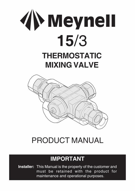
PRODUCT MANUAL
15/3THERMOSTATICMIXING VALVE
IMPORTANTInstaller: This Manual is the property of the customer and
must be retained with the product formaintenance and operational purposes.
2
PageSAFETY WARNINGS 3
ADVICE 3
INTRODUCTION 4
DESCRIPTION 4
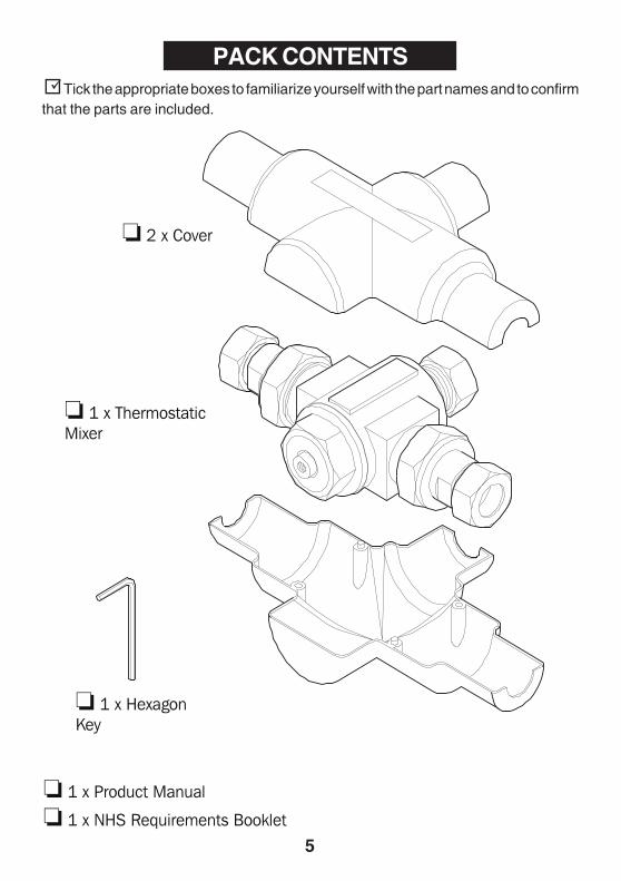
PACK CONTENTS 5
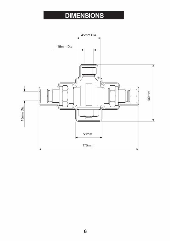
DIMENSIONS 6
SPECIFICATION 7
INSTALLATION 9
COMMISSIONING 11
FAULT DIAGNOSIS 13
MAINTENANCE 15
SPARE PARTS 25
CUSTOMER CARE Back Cover
If you experience any difficulty with the installation or operation of your newmixing valve, then please refer to the Fault Diagnosis section, beforecontacting Kohler Mira Limited. Our telephone and fax numbers can be foundon the back cover of this guide.
INDEX
3
The function of a thermostatic mixing valve is to deliver water consistently at a safetemperature. This requires that:
1. It is installed, commissioned, operated and maintained in accordance with therecommendations given in this manual.
2. Type 3 valves are only used for applications covered by their approveddesignations.
3. Periodic attention is given, as necessary, to maintain the product in goodfunctional order. Recommended guidelines are given in the MAINTENANCEsection.
4. Continued use of this product in conditions outside the specification limitsgiven in this Manual can present potential risk to users.
The use of the word ‘fail-safe’ to describe the function of a thermostatic mixing valveis both incorrect and misleading. In keeping with every other mechanism it cannot beconsidered as being functionally infallible.
Provided that the thermostatic mixing valve is installed, commissioned, operatedwithin the specification limits and maintained according to this Manual, the risk ofmalfunction, if not eliminated, is considerably reduced.
Malfunction of thermostatic mixing valves is almost always progressive in nature andwill be detected by the use of proper temperature checking and maintenance routines.
Certain types of system can result in the thermostatic mixing valve having excessive‘dead-legs’ of pipework. Others allow an auxiliary cold water supply to be added to themixed water from the mixing valve. Such systems can disguise the onset ofthermostatic mixing valve malfunction.
Ultimately, the user or attendant must exercise due diligence to ensure that the deliveryof warm water is at a stable, safe temperature. This is particularly important in suchhealthcare procedures as supervised bathing of patients unable to respond immediatelyto unsafe temperatures.
SAFETY:WARNINGS
ADVICE
4
INTRODUCTION
The Meynell 15/3Thermoscopic mixing valve is specified to meet the higheststandards of safety, comfort and economy as demanded by todays users. All Radaproducts are designed, manufactured and supported in accordance with accredited BSEN ISO 9001:1994 Quality Systems.
This Manual covers all Meynell series manufactured from June 1997.
The suffix 3 indicates that the valve has been certified for use in UK Healthcarepremises as a Type3 mixing valve under the TMV3 scheme. Where this product is tobe used in such an installation particular Application, Installation, Commissioningand Maintenance requirements apply. These are given in the section 'TYPE 3 VALVES'.
DESCRIPTION
A 1/2" point of use thermostatic mixing valve designed to supply temperaturecontrolled hot water to one or possibly two washbasin outlets.
DESCRIPTION
Meynell 15/3 A point of use model with white plastic cover.
5
PACK CONTENTS Tick the appropriate boxes to familiarize yourself with the part names and to confirmthat the parts are included.
6
45mm Dia
15mm Dia
100m
m
50mm
175mm
15m
m D
ia
DIMENSIONS

7
SPECIFICATION
Normal Operating Conditions are considered as:
- inlet dynamic pressures nominally balanced.- daily usage of 1-6 hours.- installation and usage environment not subject to extremes of temperature,
unauthorised tampering or wilful abuse.
Other ApplicationsFor information on other specific applications or suitability, refer to Kohler Mira Ltd, orLocal Agent.
Pressures and Flow Rates
Recommended Flow Rate for Basin Applications: 4 to 6 l/min.
Maximum Pressure Loss Ratio*: 10:1.
Maximum Static Pressure is 10 bar.
Operating ParametersFor Type 3 valves the supply conditions specified in Type 3 Valves - Application takeprecedence over the operating parameters which follow.
For optimum performance, maintained supply pressures should be nominallyequal.
Meynell 15/3 Flow Rate
Pressure Loss - bar
Flo
w R
ate
- Litr
es/M
in

8
Temperature
Minimum temperature differential between hot and outlet temperature: 10°C
Optimum temperature control range: 35 - 45°C
Maximum hot water temperature: 85°C (for safety, a recommended hot waterstorage temperature maintained below 85°C and for ablutionary installations atbetween 60 to 65°C).
Flow Control
The Meynell 15/3 does not have an integral flow control.
Separate outlet flow control such as a tap, mechanical timed flow control device orsolenoid is required.
The device chosen should be non-concussive in operation.
Connections
Inlet and outlet connectors are 15mm compression
Hot (H) and Cold (C) inlets are clearly marked and must be connected this way.
The inlet connections have integral strainer and checkvalve units.

9
INSTALLATION
GeneralInstallation must be carried out in accordance with these instructions, and must beconducted by designated, qualified and competent personnel.
1. Before commencing, ensure that the installation conditions comply with theinformation given in SPECIFICATION. For Type 3 valves see also Installationconditions in TYPE 3 VALVES.
2. Care must be taken during installation to prevent any risk of injury or damage.
3. The mixing valve should be positioned for easy access during use andmaintenance. All routine maintenance procedures can be conducted with themixing valve body in place (except for strainer and checkvalve access). For allmodels, allow a minimum 80 mm clearance in front of the temperature control toenable removal of the serviceable parts during maintenance.
4. The use of supply-line or zone strainers will reduce the need to remove debris ateach mixing valve point. The recommended maximum mesh aperture dimensionfor such strainers is 0.5 mm.
5. Pipework must be rigidly supported.
6. Pipework dead-legs should be kept to a minimum. The mixed water outlet pipingshould not exceed 2 m and the overall length from the hot water circuit to thedischarge point should not exceed 5 m.
7. Supply pipework layout should be arranged to minimise the effect of other outletusage upon the dynamic pressures at the mixing valve inlets.
8. Inlet and outlet threaded joint connections should be made with PTFE tape orliquid sealant. Do not use oil-based, non-setting jointing compounds.
9. To eliminate pipe debris it is essential that supply pipes are thoroughlyflushed through before connection to the mixing valve.
Procedure (see Figure 1)
INSTALLATION
1. A 50mm minimum clearance around valve to allow cover fitting and tool accessis recommended.
3. Determine the layout of pipework that suits the incoming/outlet connections.
2. Install isolator valves on supply pipework. This will assist removal of the unit ifrequired.

10
InstallationFigure 1
Meynell 15/3
Isolating valve
Isolating valve
Cold supply
Hot supply
7. Fit the cover pairing around mixer.
6. Refer to COMMISSIONING section to ensure correct outlet setting.
5. Turn on water supplies and check connections are watertight.
4. Connect the pipework to mixer, making sure that the hot and cold supplies andoutlet are correctly matched. Tighten all compression nuts and inlet connectornuts.

11
Commissioning must be carried out in accordance with these instructions,and must be conducted by designated, qualified and competent personnel.
Exercising the ThermostatThermostatic mixing valves are inclined to lose their responsiveness if not used.Valves which have been in storage, installed but not commissioned, or simply notused for some time should be exercised before setting the maximum temperature orcarrying out any tests.A simple way to provide this exercise is:
(a) ensure that the hot and cold water are available at the valve inlets, andthe outlet is open.
(b) move the temperature control rapidly from cold to hot and hot back tocold several times, pausing at each extreme.
Maximum TemperatureThe maximum blend temperature obtainable by the user should be limited, to preventaccidental selection of a temperature that is too hot.
The Meynell 15/3 is fully performance tested, and the maximum temperature is presetto approximately 42°C under ideal installation conditions at the factory. Site conditionsand personal preference may dictate that the maximum temperature has to be resetfollowing installation.
Temperature SettingMake sure that an adequate supply of hot water is available at the hot inlet of theMeynell 15/3. The minimum temperature of the hot water must be at least 10°C abovethe desired blend, however during resetting this should be close to the typical storagemaximum to offset the possibility of any blend shift due to fluctuating supplytemperatures. Make sure that both inlet isolating valves are fully open.(Temperatures should always be recorded using a thermometer with proven accuracy)
COMMISSIONING
1. Ensure outlet fitting is turned off.
2. Turn on the water supplies to the mixing valve and check for leaks.
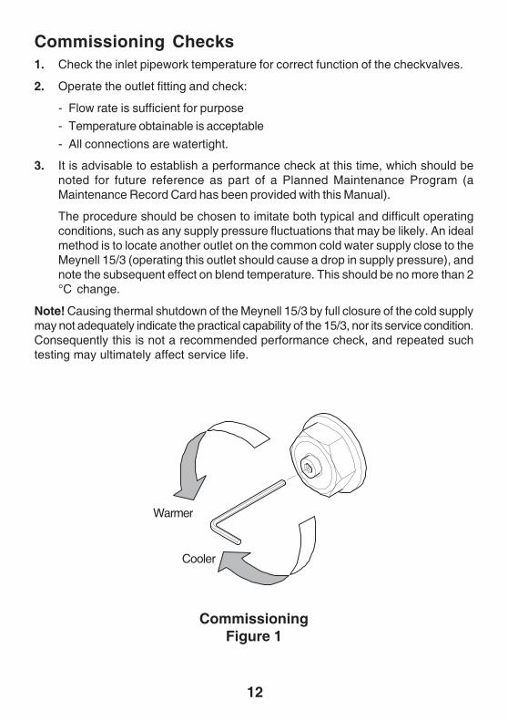
4. If the temperature needs to be adjusted, insert the 2.5mm hexagon key intothe centre of valve head.
3. Turn the outlet fitting on and allow water to run until the temperature stabilizes.Measure the blend temperature from the outlet fitting.
12
CommissioningFigure 1
Note! Causing thermal shutdown of the Meynell 15/3 by full closure of the cold supplymay not adequately indicate the practical capability of the 15/3, nor its service condition.Consequently this is not a recommended performance check, and repeated suchtesting may ultimately affect service life.
3. It is advisable to establish a performance check at this time, which should benoted for future reference as part of a Planned Maintenance Program (aMaintenance Record Card has been provided with this Manual).
The procedure should be chosen to imitate both typical and difficult operatingconditions, such as any supply pressure fluctuations that may be likely. An idealmethod is to locate another outlet on the common cold water supply close to theMeynell 15/3 (operating this outlet should cause a drop in supply pressure), andnote the subsequent effect on blend temperature. This should be no more than 2°C change.
Warmer
Cooler
1. Check the inlet pipework temperature for correct function of the checkvalves.
2. Operate the outlet fitting and check:
- Flow rate is sufficient for purpose
- Temperature obtainable is acceptable
- All connections are watertight.
Commissioning Checks

13
Symptom
1. Only hot or coldwater from mixeroutlet.
2. Fluctuating orreduced flow rate.
3. No flow rate frommixer outlet.
4. Blend temperaturedrift.
5. Maximum blendtemperature settingtoo hot or too cold.
Cause/Rectification
a. Inlet supplies reversed (hot supply to coldsupply).
b. No hot water reaching mixer.c. Check strainers and inlet/outlet fittings for
blockage.d. Installation conditions continuously
outside operating parameters: refer toSPECIFICATION, and 2.e. below.
Normal function of the thermostatic control whenoperating conditions are unsatisfactory;a. Check strainers and inlet/outlet fittings for
blockage.b. Make sure minimum flow rate is sufficient
for supply conditions.c. Make sure the maintained inlet pressures
are nominally balanced and sufficient.d. Make sure the inlet temperatures
differentials are sufficient.e. (Subsequent to rectification of supply
conditions) Check thermostaticperformance; renew Piston Assembly ifnecessary.
a. Check strainers and inlet/outlet fittings forblockage.
b. Hot or cold supply failure.
Indicates operating conditions changed.a. Refer to symptom 2. above.b. Hot supply temperature fluctuation.c. Supply pressures fluctuating.d. Seal damage or wear. Renew seals or
replace Shuttle/Thermostat Assembly.
a. Indicates incorrect maximum temperaturesetting; refer to COMMISSIONINGsection.
b. As symptom 4. above.
FAULT DIAGNOSIS
14
Cause/Rectification
Seal wear or damage.a. Obtain Seal Kit, renew all seals.
a. (Too low) Refer to symptom 2.a-e. above.b. (Too low) Insufficient supply pressures.c. (Too high) Supply pressure too high.d. (Too high) Refer to symptom 2.a-e. above.
Symptom
6. Water leakingfrom mixer body.
7. Flow rate too highor too low.
15
MAINTENANCEMAINTENANCE
General1. The maintenance of this product must be carried out in accordance with instructions
given in this manual, and must be conducted by designated, qualified andcompetent personnel.
2. Rada products are precision-engineered and should give continued superior andsafe performance, provided:
-They are installed, commissioned, operated and maintained in accordance withthe recommendations stated in this product manual.
-Periodic attention is given as necessary to maintain the product in good functionalorder. Guidelines are given below.
3. The use of main supply-line or zone strainers (recommended maximum meshaperture dimension is 0.5 mm) will reduce the need to remove debris at eachmixing valve point.
Preventative/Precautionary Maintenance
(Planned Maintenance Programmes)
The frequency and extent of attention required will vary according to prevailing siteand operational conditions however, the following guideline schedule is suggested tocover average duty and site conditions:
1. In all other cases it is recommended that a routine of preventative maintenancebe employed which is based upon assessment of the risks to the user. Thefollowing practices are intended to support such a routine:- In-service tests- Regular temperature checking in between In-service tests- Maintenance of a log of In-service tests and temperature checks together withdetails of critical parts replacements and any other service work.
2. Thermostatic mixing valves only operate correctly when all components havebeen serviced and have been tested for correct performance. If any componentis faulty, including the thermostat the valve will not operate correctly and couldallow full hot water to pass through the valve.
3. As with all other thermostatic mixing valves, the critical sensing element in theMeynell 15/3 together with other "critical components" (table 1) will exhibit wearover a period of time and usage.

16
The designed minimum service life of all these "critical components" is 5 years providingthe Meynell 15/3 is operated with the recommended operating conditions and withinthe recommended operating parameters. However, when supply conditions and/orusage patterns do not conform to the recommended operating parameters and/or therecommended operating conditions, the thermostatic unit and other critical parts mayneed to be replaced more frequently ('recommended operating conditions' and'recommended parameters' are defined on page 7 of this product manual under theheadings of 'Normal Operating Conditions' and 'Operating Parameters').
Service ContractsTo ensure your Rada/Mira products function correctly and give continued safeperformance Service Contracts can be undertaken (subject to site survey).All Service Contract work is carried out by fully trained Rada/Mira Service Engineerswho carry a comprehensive range of genuine spare parts.For details on arranging a Service Contract please contact Aftersales/Service.
LubricantsImportant: Use silicone-only based lubricants. Do not use oil based or otherlubricant types as rapid deterioration of seals may occur.
Standard silicone-only based lubricants may be used on static seals and threads toassist refitting .
Six-monthly
Function: any in-line or integral check valves, strainers are clean and in goodworking order.
Blend temperature: check for correct blend setting. Reset as necessary.Performance: check blend temperature against a known datum (relativeCOMMISSIONING procedure), by isolating cold water supply.
Exercising the Thermostat: If the valve has not been in regular or recent use thethermostat should be exercised before any other checking. When user adjustment ofthe blend temperature is available the exercising of the thermostat can be achievedas described in COMMISSIONING. For valves with locked temperature control it isnecessary to isolate and restore each supply in turn a few times.
Performance Check
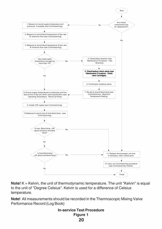
In-service TestsThe principal means for determining the continuing satisfactory performance of themixing valve is the In-service test.
The In-service test procedure is shown in Figure 1. This should be carried out at both6 to 8 weeks and 12 to 15 weeks after commissioning the valve. The results of thesetests are used to determine when, after initial commissioning, the in-service test isnext repeated.
17
Frequency of In-service TestsThe 'Guide to in-service test frequency' is shown in Figure 2. The in-service testresults over the first 28 weeks after commissioning determine the ongoing frequencyof testing shown in the right hand boxes of the Guide.Whenever a Thermoscopic Unit and/or critical components are replaced, the in-servicetest frequency should be reassessed as if it was a new valve.
Note! In-service tests should be carried out with a frequency, which identifies a needfor service work before an unsafe water temperature can result. The general principalto be observed after the first 2 or 3 in-service tests is that, intervals of future testsshould be set to those which previous tests have shown can be achieved with nomore than a small change in mixed water temperature. But in no case longer than 12months.
Temperature TestingCheck and record warm water temperature regularly to confirm correct operatingperformance of the valve. In health care applications such as hospitals, aged personsfacility, nursing homes etc. such checks must be made at least every month. Moreregular temperature checks should be made where increased risks are perceived suchas where patients are unable to immediately respond to an increase in watertemperature by either shutting the water off or removing themselves from the contactwith the water. Records of warm water temperature checks should be included in a logbook.
Thermostatic Mixing Valve Performance Records (Log Book)It is recommended that the user maintains a log of the in-service tests described herein,together with a record of any service work carried out and the replacement of criticalcomponents. It is also recommended that any maintenance personnel sign the userlog in respect of all thermostatic mixing valves examined on each attendance at theuser's premises. Refer to 'Recommended content of Maintenance Log' on page 19.
TrainingMaintenance personnel should also ensure that the user's staff are aware of theimportance of reporting temperature variations and that when detected, these shouldbe recorded in the log.
18
External surfaces may be wiped clean with a soft cloth, and if necessary, a mildwashing-up type detergent or soap solution can be used.
Warning: many household and industrial cleaning products contain mild abrasivesand chemical concentrates, and should not be used on polished, chromed or plasticsurfaces.
Should an internal malfunction occur then this will probably require component renewal.Components are precision-made, so care must be taken while servicing to avoiddamage.When ordering spare parts, please state product type, i.e.Meynell Thermostatic MixingValve 15/3 and identify part name and number. A service pack is available, containingall the seals and strainer screens that may be necessary for renewal during maintenanceor servicing. Refer to the SPARE PARTS section.
Maintenance ProceduresMaintenance must be carried out in accordance with these instructions, andmust be conducted by designated, qualified and competent personnel. TheMeynell 15/3 is designed for minimal maintenance under conditions of normal use.
19
Details of any remedial work, including part replacement, carried out to valve orsupply system.
Note! Local requirements may demand that additional information be recorded.
Details of any remedial work, including part replacement, carried out to valveor supply systemNext in-service test due dateNext in-service test data (As for initial commissioning)
It is recommended that the Maintenance Log should record the following:
Details of valve, location and use, risk level and instructions
Valve make and model
Valve unique identification number
Valve location
Date installed
Application i.e. type of discharge: bath, shower etc.
Risk assessment report number
Risk level found (e.g. vulnerability of patient)
Frequency of critical component replacement
Frequency of temperature monitoring
Responsibility for temperature monitoring
Location of temperature monitoring records
Source of spares and advice
Issue number of Product Manual (Installation, operating and maintenance instructions).
Recommended Content of Maintenance Log
Details of in-service testing and maintenance
First in-service test due dateFirst in-service test data (As for initial commissioning)Details of any remedial work carried out to valve or supply systemSecond in-service test due dateSecond in-service test data (As for initial commissioning)
Initial commissioning test data (Supply pressures and temperatures, mixed watertemperature, flow rate, result of cold water isolation test, date carried out, signatureof maintenance person).
20
Note! All measurements should be recorded in the Thermoscopic Mixing ValvePerformance Record (Log Book)
Note! K = Kelvin, the unit of thermodynamic temperature. The unit "Kelvin" is equalto the unit of "Degree Celsius". Kelvin is used for a difference of Celsiustemperature.
Start
Are criticalcomponents duefor replacement?
1. Measure & record supply temperature andpressures, if possible (see Commissioning).
No
2. Measure & record blend temperature & flow rate@ maximum flow (see Commissioning).
Has mixed watertemperature changed by
more than 1K?
3. Measure & record blend temperature & flow rate@ minimum flow (see Commissioning).
Yes
Yes4. Check/clean strainers (seeMaintenance Procedure - Inlet
Strainers).
5. Check/replace check valves (seeMaintenance Procedure - Check
valve Cartridges).
6. Check/open isolating valves.
5. Check/replace check valves (seeMaintenance Procedure - Check
valve Cartridges).
5. Check/replace check valves (seeMaintenance Procedure - Check
valve Cartridges).
7. Re-set & record blend temp.(seeCommissioning - Maximum
Temperature Setting).
8. Ensure supply temperatures & pressures and flowrate at time of test are within valve specification (see
Operating Parameters). Record all these.
No
9. Isolate CW supply (see Commissioning).
10.Measure & record max & final blend temp. (seeCommissioning).
Is max. Blend temp. >2Kabove previous recorded
value?
Is final blend temp.>2K above set blend temp?
11. Replace thermoscopic unit and,if necessary, other critical parts.
12. Carry out Commissioning procedure(see Commissioning Checks).
Yes
Yes
No
No
Finish
In-service Test ProcedureFigure 1

21
6-
8w
eek
In
-serv
ice
test
Has
mix
edw
ater
tem
per
atu
rech
ang
edb
y
mo
reth
an1
K?
24
-2
8w
eek
In-s
erv
ice
test
inte
rval
s
18
-2
1w
eek
In-s
erv
ice
test
inte
rval
s
6-
8w
eek
In-s
erv
ice
test
inte
rval
s
12
-1
5w
eek
In-s
erv
ice
test
inte
rval
s
9-
12
wee
kIn
-ser
vic
ete
stin
terv
als
12
-1
5w
eek
In-s
erv
ice
test
inte
rval
s
6-
8w
eek
In-s
erv
ice
test
inte
rval
s
Has
mix
edw
ater
tem
per
atu
rech
ang
edb
y
mo
reth
an1
K?
12
-1
5w
eek
In
-serv
ice
test
24
-2
8w
eek
In
-serv
ice
test
12
-1
5w
eek
In
-serv
ice
test
12
-1
5w
eek
In
-serv
ice
test
24
-2
8w
eek
In
-serv
ice
test
18
-2
1w
eek
In
-serv
ice
test
18
-2
1w
eek
In
-serv
ice
test
12
-1
5w
eek
In-s
erv
ice
test
inte
rval
s
6-
8w
eek
In-s
erv
ice
test
inte
rval
s
No
No
NO
TE
:M
ixed
wat
erte
mp
erat
ure
req
uir
edis
that
atst
ep2
&3
of
In-s
erv
ice
test
pro
ced
ure
.
Has
mix
edw
ater
tem
per
atu
rech
ang
edb
y
mo
reth
an1
K?
Has
mix
edw
ater
tem
per
atu
rech
ang
edb
y
mo
reth
an2
K?
Yes
Yes
No
Has
mix
edw
ater
tem
per
atu
rech
ang
edb
y
mo
reth
an2
K?
Yes
Yes
No
Has
mix
edw
ater
tem
per
atu
rech
ang
edb
y
mo
reth
an1
K?
Yes
No
Has
mix
edw
ater
tem
per
atu
rech
ang
edb
y
mo
reth
an2
K?
No
Yes
Has
mix
edw
ater
tem
per
atu
rech
ang
edb
y
mo
reth
an2
K?
No
Yes
Has
mix
edw
ater
tem
per
atu
rech
ang
edb
y
mo
reth
an1
K?
No
Yes
Has
mix
edw
ater
tem
per
atu
rech
ang
edb
y
mo
reth
an1
K?
Has
mix
edw
ater
tem
per
atu
rech
ang
edb
y
mo
reth
an2
K?
Yes
Yes
No
No
Note! K = Kelvin, the unit of thermodynamic temperature. The unit "Kelvin" is equalto the unit of "Degree Celsius". Kelvin is used for a difference of Celsiustemperature.
Guide to In-service Test FrequencyFigure 2

22
†Mixed water temperature at discharge point. = Meynell 15/3 approved designations.
Application
Note! For washbasins, it is assumed that you are washing under running water.Note! Bath fill temperatures of more than 44°C should only be available when thebather is always under the supervision of a competent person (e.g. nurse or careassistant).
Type 3 Valves
The approved designations are as follows:
M
The permitted application details are:
Designation Operating Pressure Range Application Mixed Water Temperature °C
HP-B
-HP-T44
-HP-W
-HP-S
-HP-T46
High Pressure
High Pressure
High Pressure
High Pressure
High Pressure
Shower
Bath (46oC fill)
Bath (44oC fill)
Washbasin
Bidet 38oC maximum
44oC maximum
41oC maximum
41oC maximum
46oC maximum
M
M
(shower 41oC max)
-HP-D44
-HP-D46
High Pressure
High Pressure Bath (46oC fill)
44oC maximum
46oC maximum
with diverter to shower 41oC
with diverter to shower 41oC
Bath (44oC fill)
(shower 41oC max)
-LP-S
LP-B
-LP-W
-LP-T44
-LP-T46
Low Pressure
Low Pressure
Low Pressure
Low Pressure
Low Pressure
Washbasin
Bath (44oC fill)
Bath (46oC fill)
Shower
Bidet
41oC maximum
38oC maximum
41oC maximum
44oC maximum
46oC maximum
M
M
-LP-D44
-LP-D46
Low Pressure
Low Pressure
Bath (44oC fill)
Bath (46oC fill)
with diverter to shower 41oC
44oC maximum
46oC maximum
with diverter to shower 41oC (shower 41
oC max)
(shower 41oC max)
Model Designation Code
Meynell 15/3 HP-S, HP-W, LP-S, LP-W
23
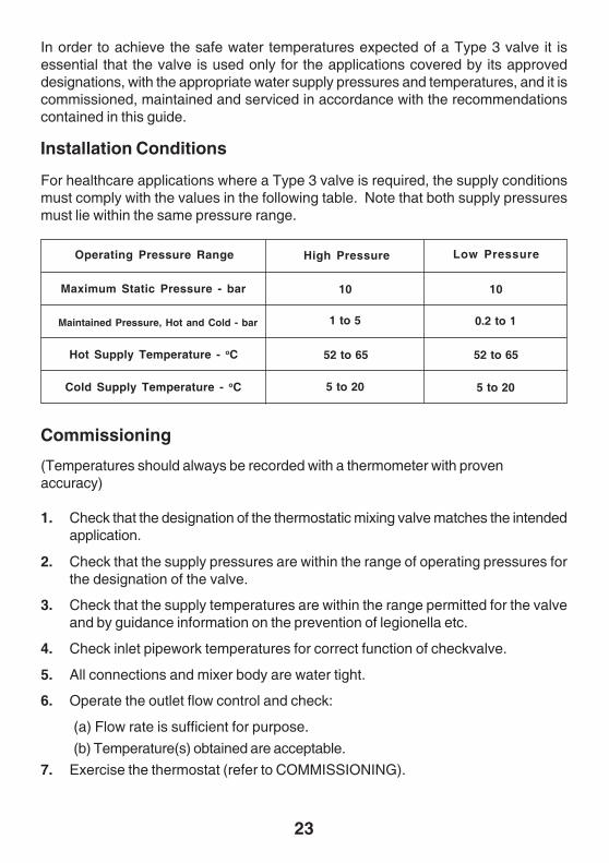
For healthcare applications where a Type 3 valve is required, the supply conditionsmust comply with the values in the following table. Note that both supply pressuresmust lie within the same pressure range.
Installation Conditions
Operating Pressure Range High Pressure Low Pressure
Maximum Static Pressure - bar
Maintained Pressure, Hot and Cold - bar
Hot Supply Temperature - oC
Cold Supply Temperature - oC
10
5 to 20
52 to 65
1 to 5
10
0.2 to 1
52 to 65
5 to 20
(Temperatures should always be recorded with a thermometer with provenaccuracy)
1. Check that the designation of the thermostatic mixing valve matches the intendedapplication.
In order to achieve the safe water temperatures expected of a Type 3 valve it isessential that the valve is used only for the applications covered by its approveddesignations, with the appropriate water supply pressures and temperatures, and it iscommissioned, maintained and serviced in accordance with the recommendationscontained in this guide.
Commissioning
2. Check that the supply pressures are within the range of operating pressures forthe designation of the valve.
3. Check that the supply temperatures are within the range permitted for the valveand by guidance information on the prevention of legionella etc.
4. Check inlet pipework temperatures for correct function of checkvalve.
5. All connections and mixer body are water tight.
6. Operate the outlet flow control and check:
(a) Flow rate is sufficient for purpose.
(b) Temperature(s) obtained are acceptable.
7. Exercise the thermostat (refer to COMMISSIONING).

24
8. Adjust the temperature of the mixed water in accordance with the instructionsin this manual and the requirement of the application and then carry out thefollowing sequence:
(a) record the temperature, and pressures if possible, of the hot and cold watersupplies.
(b) record the temperature and flow rate of the mixed water at the largest draw-offflow rate.
(c) record the temperature and flow rate of the mixed water at a smaller draw-offflow rate.
(d) isolate the cold water supply to the mixing valve and monitor the mixed watertemperature.
(e) record the maximum temperature achieved as a result of (d) and the finaltemperature.
Note! The final mixed water temperature should not exceed the values shown inTable 1 below. Any higher temperatures should only occur briefly.
(f) record the date, equipment, thermometer etc. used for the measurements.
Bidet
Shower
Washbasin
Application Mixed Water Temperature °C
40
43
43
46
48
Bath (44°C fill)
Bath (46°C fill)
Guide to Maximum Continuous Temperatures During Site TestsTable 2
Planned maintenance for Type 3 valves must use the In-service test, at the frequencygiven in the Guide to In-service test frequency and should employ Temperature Testing,Performance Log books and Training as detailed on pages 16-18.
Maintenance

25
1 SPPN0001J Piston Assembly2 SPCV0022J Strainer & Checkvalve Kit3 SPCA0018U Cover Kit
A SPSK0048J Seal Kit
SPARE PARTS
Spare Parts Lift

26
NOTES

27
NOTES

28P3290/3 © Kohler Mira Ltd, April 2002
CUSTOMER CARE
GuaranteeThis product is guaranteed against both faulty materials and manufacturing process for a period of twoyears from date of purchase, provided that the product has been installed correctly and used inaccordance with the instructions in this manual.
Any part found to be defective during the guarantee period will be replaced or repaired - at our option- without charge, provided that the product has been properly used and maintained.
Routine cleaning and maintenance should be carried out in accordance with instructions supplied.
The product should not be modified or dismantled except by a person authorised by the manufacturer.Your statutory rights are not affected by this guarantee.
Customer Service PolicyIf within the guarantee period the product does not function correctly, first check the fault findinganalysis in the manual to see if the difficulty can be resolved.
Failing this, please contact your installer to check that the product has been installed and commissionedin accordance with this manual.
If the fault can not be resolved, please contact the Customer Service Department who will try to assist,or will arrange a local Service Engineer or Agent to call and arrange a visit.
Within the guarantee period there will be no charge for parts or labour if the fault concerned is due to theproduct. However, the guarantee does not cover difficulties due to incorrect installation or misuse.
During the service visit yourself or a responsible person should be present at all times. If the ServiceEngineer or Agent can not gain access at the prearranged time a callout charge may be made.
Payment for the service visit, if applicable, should be made direct to Service Engineer or Agent usingAccess, Visa or cheque supported by a banker’s card.
Spare PartsFunctional spare parts are available for your products maintenance. Items can be identified fromspares drawing inside manual, please contact Customer Service to confirm spare and details of aspares stockist for your area. Your product serial number or date mark (if available) may be useful toidentify parts.
Meynell is a registered trade mark of subsidiariesof Kohler Mira Limited.The company reserves the right to alter productspecifications without notice.
www.meynellcontrols.com
Rada ControlsCromwell Road,Cheltenham, England,GL52 5EP, UK.
Tel.: + 44 (0)1242 221221
Fax.: + 44 (0)1242 221925
CUSTOMER CARE
CUSTOMER CARE