p387 calcul imbinari in engleza
TRANSCRIPT

8/13/2019 p387 Calcul Imbinari in Engleza
http://slidepdf.com/reader/full/p387-calcul-imbinari-in-engleza 1/105
SCI PUBLICATION P387
Steel Building Design:
Worked examples for students
In accordance with Eurocodes
and the UK National Annexes
Edited by:
M E Brettle B Eng
Reworked in accordance with the UK National Annexes by
D G Brown C Eng MICE
Published by:
The Steel Construction Institute
Silwood Park
Ascot
Berkshire SL5 7QN
Tel: 01344 636525
Fax: 01344 636570
P387: Steel Building Design: Worked Examples for Students
Discuss me ...
C r e a
t e d
o n
0 3
F e
b r u a r y
2 0 1 1
T h i s m a
t e r i a
l i s c o p y r i g
h t - a
l l r i g
h t s r e s e r v e
d .
U s e
o f t h i s d o c u m e n t
i s s u
b j e c
t t o
t h e
t e r m s a n
d
c o n
d i t i o n s o
f t h e
S t e e
l b i z L i c e n c e
A g r e e m e n
t

8/13/2019 p387 Calcul Imbinari in Engleza
http://slidepdf.com/reader/full/p387-calcul-imbinari-in-engleza 2/105
ii Printed 06/05/09
2009 The Steel Construction Institute
Apart from any fair dealing for the purposes of research or private study or criticism or review, as permitted under the
Copyright Designs and Patents Act, 1988, this publication may not be reproduced, stored or transmitted, in any form or by
any means, without the prior permission in writing of the publishers, or in the case of reprographic reproduction only in
accordance with the terms of the licences issued by the UK Copyright Licensing Agency, or in accordance with the terms
of licences issued by the appropriate Reproduction Rights Organisation outside the UK.
Enquiries concerning reproduction outside the terms stated here should be sent to the publishers, The Steel Construction
Institute, at the address given on the title page.
Although care has been taken to ensure, to the best of our knowledge, that all data and information contained herein are
accurate to the extent that they relate to either matters of fact or accepted practice or matters of opinion at the time of
ublication, The Steel Construction Institute, the authors and the reviewers assume no responsibility for any errors in or
misinterpretations of such data and/or information or any loss or damage arising from or related to their use.
Publications supplied to the Members of the Institute at a discount are not for resale by them.
Publication Number: SCI P387
ISBN 978-1-85942-191-8
British Library Cataloguing-in-Publication Data.
A catalogue record for this book is available from the British Library.
P387: Steel Building Design: Worked Examples for Students
Discuss me ...
C r e a
t e d o n
0 3 F e
b r u a r y
2 0 1 1
T h i s m a
t e r i a
l i s c o p y r i g h
t - a
l l r i g
h t s r e s e r v e
d .
U s e o
f t h i s d o c u m e n
t i s s u
b j e c
t t o t h e
t e r m s a n
d c o n
d i t i o n s o
f t h e
S t e e
l b i z
L i c e n c e
A g r e e m e n
t
8/13/2019 p387 Calcul Imbinari in Engleza
http://slidepdf.com/reader/full/p387-calcul-imbinari-in-engleza 3/105
iii Printed 06/05/09
FOREWORD
The Structural Eurocodes are a set of structural design standards, developed by CEN over
the last 30 years, to cover the design of all types of structures in steel, concrete, timber,
masonry and aluminium. In the UK they are published by BSI under the designations
BS EN 1990 to BS EN 1999, each in a number of ‘Parts’. Each Part will be accompanied
by a National Annex that implements the CEN document and adds certain UK-specific
provisions.
This publication was originally developed as a teaching resource for university lecturers
and students, although it will also be of interest to practising designers. It offers a general
overview of design to the Eurocodes and includes a set of design worked examples for
structural elements within a notional building. The original SCI publication (P376)
includes a version of the set of examples in which the values of partial factors and other
parameters where national choice is allowed are the values recommended within the
Eurocode parts. In the present publication, all the examples have been re-worked usingvalues given in the UK National Annexes.
The author of the introductory text is Miss M E Brettle of The Steel Construction
Institute. Mr A L Smith and Mr D G Brown of The Steel Construction Institute
contributed to the worked examples. The re-working to incorporate the UK National
Annex values was carried out by Mr D G Brown.
The worked examples were written or checked by:
Dr A J Bell University of Manchester
Prof. I Burgess University of Sheffield
Mr M Cullen Glasgow Caledonian University
Dr B Davison University of Sheffield
Dr Y Du SCI (formerly of University of Birmingham)
Dr L Gardner Imperial College London
Dr A Kamtekar University of Birmingham
Dr B Kim University of Plymouth
Dr D Lam University of Leeds
Dr L-Y Li University of Birmingham (formerly of Aston University)
Dr J T Mottram University of Warwick
Mr L P Narboux Normacadre (formerly of SCI)
Dr P Palmer University of Brighton
Dr K M Peebles University of Dundee
Dr J Rizzuto Faber Maunsell (formerly of University of Coventry)
Dr M Saidani University of Coventry
Dr K A Seffen University of Cambridge
Mr N Seward University of Wales, Newport
Prof. P R S Speare City University
Mr M Theofanous Imperial College London (formerly of SCI)
Dr W Tizani University of Nottingham
The preparation of P376 was funded by Corus Construction Services and Development,
and their support is gratefully acknowledged. The preparation of the present publicationwas funded by The Steel Construction Institute.
P387: Steel Building Design: Worked Examples for Students
Discuss me ...
C r e a
t e d o n
0 3 F e
b r u a r y
2 0 1 1
T h i s m a
t e r i a
l i s c o p y r i g h
t - a
l l r i g
h t s r e s e r v e
d .
U s e o
f t h i s d o c u m e n
t i s s u
b j e c
t t o t h e
t e r m s a n
d c o n
d i t i o n s o
f t h e
S t e e
l b i z
L i c e n c e
A g r e e m e n
t

8/13/2019 p387 Calcul Imbinari in Engleza
http://slidepdf.com/reader/full/p387-calcul-imbinari-in-engleza 4/105
iv Printed 06/05/09
P387: Steel Building Design: Worked Examples for Students
Discuss me ...
C r e a
t e d o n
0 3 F e
b r u a r y
2 0 1 1
T h i s m a
t e r i a
l i s c o p y r i g h
t - a
l l r i g
h t s r e s e r v e
d .
U s e o
f t h i s d o c u m e n
t i s s u
b j e c
t t o t h e
t e r m s a n
d c o n
d i t i o n s o
f t h e
S t e e
l b i z
L i c e n c e
A g r e e m e n
t
8/13/2019 p387 Calcul Imbinari in Engleza
http://slidepdf.com/reader/full/p387-calcul-imbinari-in-engleza 5/105
v Printed 06/05/09
ContentsPage No.
FOREWORD III SUMMARY VI 1 SCOPE 1 2 STRUCTURAL EUROCODES SYSTEM 2
2.1 National Annexes 3 2.2 Geometrical axes convention 4 2.3 Terminology and symbols 4
3 BASIS OF STRUCTURAL DESIGN (BS EN 1990) 5 3.1 Limit state design 5 3.2 Combination of actions 6
4 DESIGN PROCESS 10 5 BUILDING DESIGN 11
5.1 Material properties 11 5.2 Section classification 13 5.3 Resistance 13 5.4 Joints 16 5.5 Robustness 17 5.6 Fire design / protection 17 5.7 Corrosion protection 18
6 WORKED EXAMPLES 19 7 BIBLIOGRAPHY 97
7.1 SCI and SCI/BCSA publications 97 7.2 Other publications 97 7.3 Sources of electronic information 98 7.4 Structural Eurocodes 98 7.5 Product Standards 99
P387: Steel Building Design: Worked Examples for Students
Discuss me ...
C r e a
t e d o n
0 3 F e
b r u a r y
2 0 1 1
T h i s m a
t e r i a
l i s c o p y r i g h
t - a
l l r i g
h t s r e s e r v e
d .
U s e o
f t h i s d o c u m e n
t i s s u
b j e c
t t o t h e
t e r m s a n
d c o n
d i t i o n s o
f t h e
S t e e
l b i z
L i c e n c e
A g r e e m e n
t
8/13/2019 p387 Calcul Imbinari in Engleza
http://slidepdf.com/reader/full/p387-calcul-imbinari-in-engleza 6/105
vi Printed 06/05/09
SUMMARY
This publication offers a general overview of the design of steel framed buildings to the
structural Eurocodes and includes a set of worked examples showing the design of
structural elements within a notional building. It does not present structural theory or
explain detailed design rules. It is intended to be of particular help in undergraduate
teaching, although it will also provide guidance to practising designers who want to
become acquainted with design to the Eurocodes.
The text discusses the structure of the Eurocode system and the sections contained within
a Eurocode Part. It introduces the terminology, and the conventions used for axes and
symbols. The document introduces the contents of BS EN 1993 (Eurocode 3) and
BS EN 1994 (Eurocode 4) that relate to the design of structural steelwork and steel and
composite structures respectively.
The worked examples have all been evaluated using the values of parameters and designoptions given in the UK National Annexes and are therefore appropriate for structures
which are to be constructed in the UK.
The publication has been produced with the assistance of structural design lecturers, who
were responsible for writing and checking the majority of the original worked examples
presented in Section 6.
P387: Steel Building Design: Worked Examples for Students
Discuss me ...
C r e a
t e d o n
0 3 F e
b r u a r y
2 0 1 1
T h i s m a
t e r i a
l i s c o p y r i g h
t - a
l l r i g
h t s r e s e r v e
d .
U s e o
f t h i s d o c u m e n
t i s s u
b j e c
t t o t h e
t e r m s a n
d c o n
d i t i o n s o
f t h e
S t e e
l b i z
L i c e n c e
A g r e e m e n
t

8/13/2019 p387 Calcul Imbinari in Engleza
http://slidepdf.com/reader/full/p387-calcul-imbinari-in-engleza 7/105
1
1 SCOPE
This publication gives a general overview of structural design to the structural
Eurocodes and includes a set of worked examples showing the design of
structural elements within a notional building.
The introductory text presents a brief overview of the Eurocodes with respect to
the sections, conventions and terminology used. The requirements of
BS EN 1993 (steel structures) and BS EN 1994 (composite steel and concrete
structures) are briefly introduced with respect to building design. Information is
also given for the relevant sections of BS EN 1992 (Eurocode 2), which covers
the design of concrete elements in composite structures. Robustness, fire design
and corrosion protection are briefly discussed.
The publication has been produced with the assistance of structural designlecturers, who have been responsible for writing and checking the majority of
the worked examples presented in Section 6. The set of worked examples
present the design of structural elements that may be found in a braced steel
framed notional building.
Further design guidance may be found in the documents listed in Section 7 of
this publication.
Within the worked examples, frequent reference is made to Access Steel
documents. These are a series of publicly available guidance notes on the
application of the structural Eurocodes to steelwork design. Many of these notes
have the status of non-contradictory complementary information (NCCI), havingreceived endorsement from across Europe. Some notes are UK-specific, relating
to UK practice alone. The Access Steel website may be found at www.access-
steel.com.
Reference is also made to SCI publication P363, Steel building design: Design
data. That publication contains comprehensive section property data and
member resistances for a wide range of steel sections. The member resistances
in P363 have been calculated using the UK National Annexes, and should be
directly comparable with the resistances calculated in the present publication.
P363 is available from the SCI. Section properties and member resistances are
also available from the Corus website
(www.corusconstruction.com/en/reference/software).
P387: Steel Building Design: Worked Examples for Students
Discuss me ...
C r e a
t e d o n
0 3 F e
b r u a r y
2 0 1 1
T h i s m a
t e r i a
l i s c o p y r i g h
t - a
l l r i g
h t s r e s e r v e
d .
U s e o
f t h i s d o c u m e n
t i s s u
b j e c
t t o t h e
t e r m s a n
d c o n
d i t i o n s o
f t h e
S t e e
l b i z
L i c e n c e
A g r e e m e n
t
8/13/2019 p387 Calcul Imbinari in Engleza
http://slidepdf.com/reader/full/p387-calcul-imbinari-in-engleza 8/105
2
2 STRUCTURAL EUROCODES SYSTEM
There are ten separate Structural Eurocodes:
EN 1990 Basis of structural design
EN 1991 Actions on structures
EN 1992 Design of concrete structures
EN 1993 Design of steel structures
EN 1994 Design of composite steel and concrete structures
EN 1995 Design of timber structures
EN 1996 Design of masonry structures
EN 1997 Geotechnical design
EN 1998 Design of structures for earthquake resistance
EN 1999 Design of Aluminium Structures
Each Eurocode is comprised of a number of Parts, which are published asseparate documents. Each Part consists of:
Main body of text
Normative annexes These form the full text of the Eurocode Part
Informative annexes
The full text of each Eurocode Part is issued initially by CEN in three languages
with the above ‘EN’ designation. The full text is then provided with a front
cover by each national standards body and published within that country using a
designation with the national prefix – for example EN 1990 is published by BSI
as BS EN 1990. The Eurocode text may be followed by a National Annex (seeSection 2.1 below) or a National Annex may be published separately.
As this set of worked examples are for use in the UK, the full
BS EN designation has generally been adopted in the text.
Thus the information contained in the full text of the Eurocodes is the same for
each country in Europe. Most parts of the structural Eurocodes present the
information using Principles and Application Rules. Principles are denoted by
the use of a letter P after the clause number e.g. 1.2(3)P, whereas Application
Rules do not contain a letter P e.g. 1.2(3). The former must be followed, to
achieve compliance; the latter are rules that will achieve compliance with the
Principles but it is permissible to use alternative design rules, provided that they
accord with the Principles (see BS EN 1990, 1.4(5)).
The general principle adopted in drafting the Eurocodes was that there would be
no duplication of Principles or Application Rules. Thus the design basis given in
BS EN 1990 applies irrespective of the construction material or the type of
structure. For each construction material, requirements that are independent of
structural form are given in ‘General’ Parts, one for each aspect of design, and
form-specific requirements (such as for bridges) are given in other Parts (bridge
rules are in Parts 2 of the respective material Eurocodes). Therefore, when
designing a structure, many separate Eurocode Parts will be required.
P387: Steel Building Design: Worked Examples for Students
Discuss me ...
C r e a
t e d o n
0 3 F e
b r u a r y
2 0 1 1
T h i s m a
t e r i a
l i s c o p y r i g h
t - a
l l r i g
h t s r e s e r v e
d .
U s e o
f t h i s d o c u m e n
t i s s u
b j e c
t t o t h e
t e r m s a n
d c o n
d i t i o n s o
f t h e
S t e e
l b i z
L i c e n c e
A g r e e m e n
t

8/13/2019 p387 Calcul Imbinari in Engleza
http://slidepdf.com/reader/full/p387-calcul-imbinari-in-engleza 9/105
3
The Structural Eurocodes that may be required for the design of a steel and
concrete composite building are:
BS EN 1990 Basis of structural design
BS EN 1991 Actions on structures
BS EN 1992 Design of concrete structuresBS EN 1993 Design of steel structures
BS EN 1994 Design of composite steel and concrete structures
BS EN 1997 Geotechnical design
BS EN 1998 Design of structures for earthquake resistance
In addition to references between structural Eurocode Parts, references to other
Standards may be given e.g. product standards.
2.1 National Annexes
Within the full text of a Eurocode, national choice is allowed in the setting ofsome factors and in the choice of some design methods (i.e. the selection of
particular Application Rules); the choices are generally referred to as Nationally
Determined Parameters (NDP) and these are published in a National Annex.
The National Annex, where allowed in the Eurocode, will:
Specify which design method to use.
Specify what value to use for a factor.
State whether an informative annex may be used.
In addition, the National Annex may give references to resources that containnon-contradictory complimentary information (NCCI) that will assist the
designer. Several National Annexes refer to http://www.steel-ncci.co.uk which
has been created to contain NCCI and will be updated with additional resources
over time.
The guidance given in a National Annex applies to structures that are to be
constructed within that country. National Annexes are likely to differ between
countries within Europe.
The National Annexes for the country where the structure is to be
constructed should always be consulted in the design of a structure.
Within this publication, the values recommended in the UK National
Annexes have been used.
P387: Steel Building Design: Worked Examples for Students
Discuss me ...
C r e a
t e d o n
0 3 F e
b r u a r y
2 0 1 1
T h i s m a
t e r i a
l i s c o p y r i g h
t - a
l l r i g
h t s r e s e r v e
d .
U s e o
f t h i s d o c u m e n
t i s s u
b j e c
t t o t h e
t e r m s a n
d c o n
d i t i o n s o
f t h e
S t e e
l b i z
L i c e n c e
A g r e e m e n
t
8/13/2019 p387 Calcul Imbinari in Engleza
http://slidepdf.com/reader/full/p387-calcul-imbinari-in-engleza 10/105
4
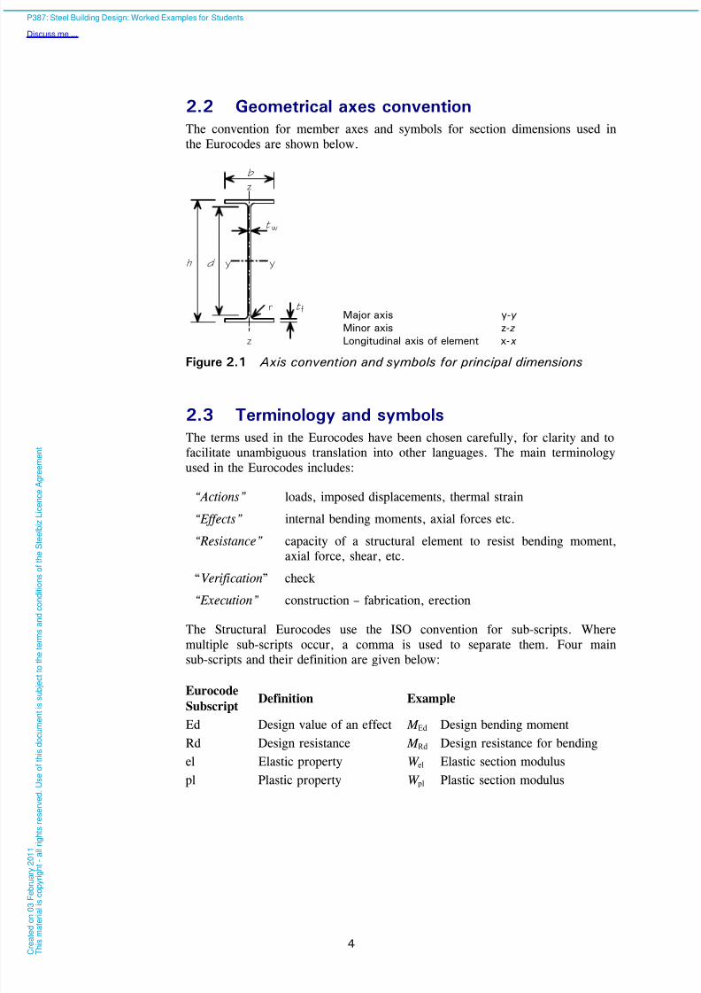
2.2 Geometrical axes convention
The convention for member axes and symbols for section dimensions used in
the Eurocodes are shown below.
2.3 Terminology and symbols
The terms used in the Eurocodes have been chosen carefully, for clarity and to
facilitate unambiguous translation into other languages. The main terminology
used in the Eurocodes includes:
“Actions” loads, imposed displacements, thermal strain
“Effects” internal bending moments, axial forces etc.
“Resistance” capacity of a structural element to resist bending moment,
axial force, shear, etc.
“Verification” check
“Execution” construction – fabrication, erection
The Structural Eurocodes use the ISO convention for sub-scripts. Where
multiple sub-scripts occur, a comma is used to separate them. Four main
sub-scripts and their definition are given below:
EurocodeSubscript
Definition Example
Ed Design value of an effect M Ed Design bending moment
Rd Design resistance M Rd Design resistance for bending
el Elastic property W el Elastic section modulus
pl Plastic property W pl Plastic section modulus
z
z
y y
f
w
b
h d
r
t
tMajor axis y-y
Minor axis z- z
Longitudinal axis of element x- x
Figure 2.1 Axis convention and symbols for principal dimensions
P387: Steel Building Design: Worked Examples for Students
Discuss me ...
C r e a
t e d o n
0 3 F e
b r u a r y
2 0 1 1
T h i s m a
t e r i a
l i s c o p y r i g h
t - a
l l r i g
h t s r e s e r v e
d .
U s e o
f t h i s d o c u m e n
t i s s u
b j e c
t t o t h e
t e r m s a n
d c o n
d i t i o n s o
f t h e
S t e e
l b i z
L i c e n c e
A g r e e m e n
t

8/13/2019 p387 Calcul Imbinari in Engleza
http://slidepdf.com/reader/full/p387-calcul-imbinari-in-engleza 11/105
5
3 BASIS OF STRUCTURAL DESIGN
(BS EN 1990)
BS EN 1990 can be considered as the ‘core’ document of the structural
Eurocode system because it establishes the principles and requirements for the
safety, serviceability and durability of structures.
3.1 Limit state design
The information given in the Structural Eurocodes is based on limit state design.
BS EN 1990 defines a limit state as a ‘state beyond which the structure no
longer fulfils the relevant design criteria’.
Limit state design provides a consistent reliability against the failure of
structures by ensuring that limits are not exceeded when design values of
actions, material and product properties, and geotechnical data are considered.
Design values are obtained by applying partial factors to characteristic values1
of actions and properties.
Limit state design considers the resistance, serviceability and durability of a
structure. All relevant design situations should be considered for the structure.
The design situations considered by the Eurocodes are:
Persistent – the normal use of the structure.
Transient – temporary situations, e.g. execution.
Accidental – exceptional events, e.g. fire, impact or explosion.
Seismic – seismic events that may act on the structure.
Two limit states are considered during the design process: ultimate and
serviceability.
3.1.1 Ultimate limit states
Ultimate limit states are those that relate to the failure of a structural member or
a whole structure. Design verifications that relate to the safety of the people in
and around the structure are ultimate limit state verifications.
Limit states that should be considered where relevant are:
Loss of equilibrium of the structure or a structural member.
Failure of the structure or a structural member caused by: excessive
deformation causing a mechanism, rupture, loss of stability, fatigue or other
time-dependent effects.
1 The term “characteristic value” applies to actions, material properties and geometrical properties and is defined for each in BS EN 1990. Generally, it means a representative
value that has a certain (low) probability of being exceeded (where a greater value would
be more onerous) or of not being exceeded (where a lesser value would be more onerous).
P387: Steel Building Design: Worked Examples for Students
Discuss me ...
C r e a
t e d o n
0 3 F e
b r u a r y
2 0 1 1
T h i s m a
t e r i a
l i s c o p y r i g h
t - a
l l r i g
h t s r e s e r v e
d .
U s e o
f t h i s d o c u m e n
t i s s u
b j e c
t t o t h e
t e r m s a n
d c o n
d i t i o n s o
f t h e
S t e e
l b i z L i c e n c e
A g r e e m e n
t
8/13/2019 p387 Calcul Imbinari in Engleza
http://slidepdf.com/reader/full/p387-calcul-imbinari-in-engleza 12/105
6
Failure of the supports or foundations, including excessive deformation of
the supporting ground.
3.1.2 Serviceability limit states
Serviceability limit states concern the functioning of the structure under normal use, the comfort of the people using the structure and the appearance of the
structure. Serviceability limit states may be irreversible or reversible.
Irreversible limit states occur where some of the consequences remain after the
actions that exceed the limit have been removed, e.g. there is permanent
deformation of a beam or cracking of a partition wall. Reversible limit states
occur when none of the consequences remain after the actions that exceed the
limit have been removed, i.e. the member stresses are within its elastic region.
Criteria that are considered during serviceability limit state design checks are:
Deflections that affect the appearance of the structure, the comfort of its
users and its functionality. Vibrations that may cause discomfort to users of the structure and restrict the
functionality of the structure.
Damage that may affect the appearance or durability of the structure.
The Eurocodes do not specify any limits for serviceability criteria, but limits
may be given in the National Annexes. The limits should be defined for each
project, based on the use of the member and the Client’s requirements.
3.2 Combination of actions
BS EN 1990 requires the structure or member to be designed for the critical
load cases that are determined by combining actions that can occur
simultaneously. This implies that all variable actions that occur concurrently
should be considered in a single combination. However, for buildings, note 1 of
clause A1.2.1(1) of BS EN 1990 allows the critical combination to be
determined from not more than two variable actions. Therefore, engineering
judgement may be used to determine the two variable actions that may occur
together to produce the critical combination of actions for the whole building or
the particular structural member under consideration within the building.
3.2.1 Ultimate limit state
Two methods for determining the combination of actions to be used for the
persistent or transient ultimate limit state (ULS) are presented in BS EN 1990.
The methods are to use expression (6.10) on its own or, for strength or
geotechnical limit states, to determine the least favourable combination from
expression (6.10a) and (6.10b). The National Annex for the country in which
the building is to be constructed must be consulted for guidance on which
method to use – in the UK, either expression (6.10) or the combination of
(6.10a) and (6.10b) may be used.
Where multiple independent variable actions occur simultaneously, the
Eurocodes consider one to be a leading variable action (Qk,1) and the other(s) to
be accompanying variable actions (Qk,i). A leading variable action is one thathas the most onerous effect on the structure or member.
P387: Steel Building Design: Worked Examples for Students
Discuss me ...
C r e a
t e d o n
0 3 F e
b r u a r y
2 0 1 1
T h i s m a
t e r i a
l i s c o p y r i g h
t - a
l l r i g
h t s r e s e r v e
d .
U s e o
f t h i s d o c u m e n
t i s s u
b j e c
t t o t h e
t e r m s a n
d c o n
d i t i o n s o
f t h e
S t e e
l b i z
L i c e n c e
A g r e e m e n
t
8/13/2019 p387 Calcul Imbinari in Engleza
http://slidepdf.com/reader/full/p387-calcul-imbinari-in-engleza 13/105
7
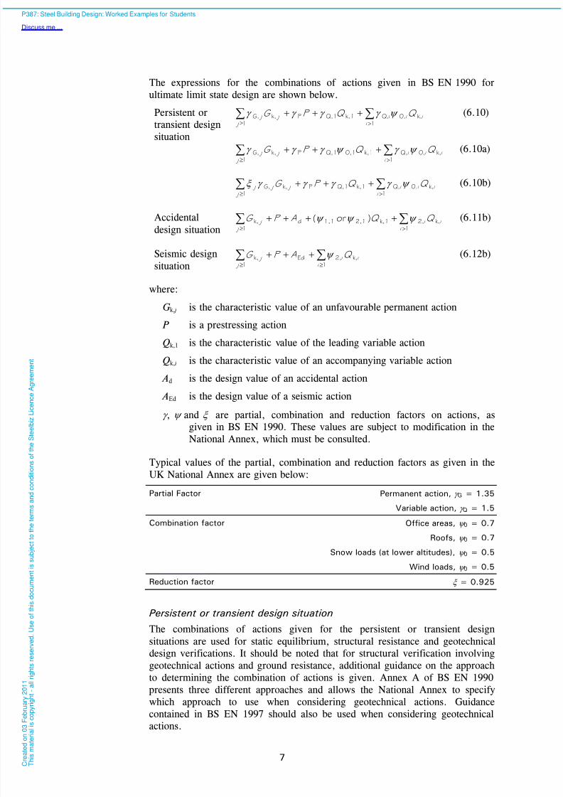
The expressions for the combinations of actions given in BS EN 1990 for
ultimate limit state design are shown below.
Persistent or
transient design
situation
i i i
j j
j Q Q P G k,0,
1
iQ,k,1Q,1Pk,
1
G,
(6.10)
i i i
i j j
j Q Q P G k,0,
1
Q,k,10,1Q,1Pk,
1
G,
(6.10a)
i i i
i j j j
j Q Q P G k,0,
1
Q,k,1Q,1Pk,G,
1
(6.10b)
Accidental
design situationi
i i
j j Q Q AP G k,
1
2,k,12,11,1d
1
k, )or(
(6.11b)
Seismic design
situationi
i i
j j Q AP G k,
1
2,Ed
1
k,
(6.12b)
where:
G k, j is the characteristic value of an unfavourable permanent action
P is a prestressing action
Qk,1 is the characteristic value of the leading variable action
Qk,i is the characteristic value of an accompanying variable action
Ad is the design value of an accidental action
AEd is the design value of a seismic action
, and are partial, combination and reduction factors on actions, asgiven in BS EN 1990. These values are subject to modification in the
National Annex, which must be consulted.
Typical values of the partial, combination and reduction factors as given in the
UK National Annex are given below:
Partial Factor Permanent action, G = 1.35
Variable action, Q = 1.5
Combination factor Office areas, 0 = 0.7
Roofs, 0 = 0.7
Snow loads (at lower altitudes), 0 = 0.5
Wind loads, 0 = 0.5
Reduction factor = 0.925
Persistent or transient design situation
The combinations of actions given for the persistent or transient design
situations are used for static equilibrium, structural resistance and geotechnical
design verifications. It should be noted that for structural verification involving
geotechnical actions and ground resistance, additional guidance on the approach
to determining the combination of actions is given. Annex A of BS EN 1990
presents three different approaches and allows the National Annex to specify
which approach to use when considering geotechnical actions. Guidance
contained in BS EN 1997 should also be used when considering geotechnical
actions.
P387: Steel Building Design: Worked Examples for Students
Discuss me ...
C r e a
t e d o n
0 3 F e
b r u a r y
2 0 1 1
T h i s m a
t e r i a
l i s c o p y r i g h
t - a
l l r i g
h t s r e s e r v e
d .
U s e o
f t h i s d o c u m e n
t i s s u
b j e c
t t o t h e
t e r m s a n
d c o n
d i t i o n s o
f t h e
S t e e
l b i z
L i c e n c e
A g r e e m e n
t

8/13/2019 p387 Calcul Imbinari in Engleza
http://slidepdf.com/reader/full/p387-calcul-imbinari-in-engleza 14/105
8
Accidental design situation
The combination of actions for the accidental design situation can be used to
determine a design value that either;
contains an accidental action (e.g. impact, fire); or
applies to a situation after an accidental action has occurred (e.g. after a fire).
In the latter case Ad = 0.
Seismic design situation
This combination of actions and guidance given in BS EN 1998 should be used
when seismic actions are being considered.
3.2.2 Serviceability Limit State
The expressions for the combinations of actions given in BS EN 1990 for
serviceability limit state design are shown below.
Characteristic
combinationi
i i
j j Q Q P G k,
1
0,k,1
1
k,
(6.14b)
Frequent combination i i
i j
j Q Q P G k,
1
2,k,11,1
1
k,
(6.15b)
Quasi-permanent
combinationi
i i
j j Q P G k,
1
2,
1
k,
(6.16b)
Characteristic combination
This combination of actions should be used when considering an irreversible
serviceability limit state. The characteristic combination should be used when
considering the functioning of the structure, damage to finishes or non-structural
elements.
Frequent combination
Reversible serviceability limit states are covered by the frequent combination of
actions. This combination could be used when checking the non-permanent
vertical displacement of a floor that supports a machine that is sensitive to
vertical alignment.
Quasi-permanent combination
The quasi-permanent combination of actions should be used when considering
reversible limit states or long term effects. When considering the appearance of
a structure, the quasi-permanent combination should be used.
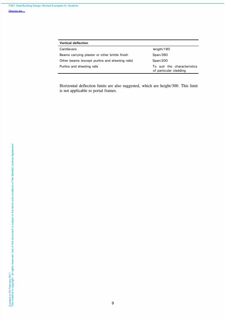
BS EN 1990 states that advice on which expression (6.14b) to (6.16b) to use is
given in the material Standard. For steelwork, the National Annex to
BS EN 1993 gives suggested limits for calculated vertical deflections and
advises that the permanent loads should not be included. The suggested limits
are given below.
P387: Steel Building Design: Worked Examples for Students
Discuss me ...
C r e a
t e d o n
0 3 F e
b r u a r y
2 0 1 1
T h i s m a
t e r i a
l i s c o p y r i g h
t - a
l l r i g
h t s r e s e r v e
d .
U s e o
f t h i s d o c u m e n
t i s s u
b j e c
t t o t h e
t e r m s a n
d c o n
d i t i o n s o
f t h e
S t e e
l b i z
L i c e n c e
A g r e e m e n
t
8/13/2019 p387 Calcul Imbinari in Engleza
http://slidepdf.com/reader/full/p387-calcul-imbinari-in-engleza 15/105
9
Vertical deflection
Cantilevers length/180
Beams carrying plaster or other brittle finish Span/360Other beams (except purlins and sheeting rails) Span/200
Purlins and sheeting rails To suit the characteristics
of particular cladding
Horizontal deflection limits are also suggested, which are height/300. This limit
is not applicable to portal frames.
P387: Steel Building Design: Worked Examples for Students
Discuss me ...
C r e a
t e d o n
0 3 F e
b r u a r y
2 0 1 1
T h i s m a
t e r i a
l i s c o p y r i g h
t - a
l l r i g
h t s r e s e r v e
d .
U s e o
f t h i s d o c u m e n
t i s s u
b j e c
t t o t h e
t e r m s a n
d c o n
d i t i o n s o
f t h e
S t e e
l b i z
L i c e n c e
A g r e e m e n
t
8/13/2019 p387 Calcul Imbinari in Engleza
http://slidepdf.com/reader/full/p387-calcul-imbinari-in-engleza 16/105
10
4 DESIGN PROCESS
The procedures that should be followed when designing a structure are:
1. Choose the structural frame concept, considering:
The layout of the structural members
The type of connections, i.e. simple, semi-rigid or moment resisting
The stability of the structure at all stages (during construction,
use and demolition).
2. Determine the actions (loading) on the structure and its members.
3. Analyse the structure, including evaluation of frame stability.
4. Design individual members and connections.
5. Verify robustness.
6. Choose the steel sub-grade.
7. Specify appropriate protection of steel, e.g. against fire and corrosion.
P387: Steel Building Design: Worked Examples for Students
Discuss me ...
C r e a
t e d o n
0 3 F e
b r u a r y
2 0 1 1
T h i s m a
t e r i a
l i s c o p y r i g h
t - a
l l r i g
h t s r e s e r v e
d .
U s e o
f t h i s d o c u m e n
t i s s u
b j e c
t t o t h e
t e r m s a n
d c o n
d i t i o n s o
f t h e
S t e e
l b i z
L i c e n c e
A g r e e m e n
t
8/13/2019 p387 Calcul Imbinari in Engleza
http://slidepdf.com/reader/full/p387-calcul-imbinari-in-engleza 17/105
11
5 BUILDING DESIGN
BS EN 1993-1-1 gives generic design rules for steel structures and specific
guidance for structural steelwork used in buildings. It presents design rules for
use with the other parts of BS EN 1993 for steel structures and with
BS EN 1994 for composite steel and concrete structures.
BS EN 1993-1 comprises twelve parts (BS EN 1993-1-1 to BS EN 1993-1-12).
When designing orthodox steel framed buildings, the following parts of
BS EN 1993-1 will be required:
BS EN 1993-1-1 General rules and rules for buildings
BS EN 1993-1-2 Structural fire design
BS EN 1993-1-3 Supplementary rules for cold-formed members and sheeting
BS EN 1993-1-5 Plated structural elementsBS EN 1993-1-8 Design of joints
BS EN 1993-1-10 Material toughness and through-thickness properties
When designing a steel and concrete composite building, the following parts of
Eurocode 4 will be required:
BS EN 1994-1-1 Design of composite steel and concrete structures - General
rules and rules for buildings
BS EN 1994-1-2 Design of composite steel and concrete structures -
Structural fire design
In addition to the above, the following Eurocode is needed:
BS EN 1992-1-1 Design of concrete structures - General rules and rules for
buildings
5.1 Material properties
5.1.1 Steel grades
The rules in BS EN 1993-1-1 relate to structural steel grades S235 to S460 in
accordance with BS EN 10025, BS EN 10210 or BS EN 10219 and thus cover
all the structural steels likely to be used in buildings. In exceptional
circumstances, components might use higher strength grades; BS EN 1993-1-12
gives guidance on the use of BS EN 1993-1-1 design rules for higher strength
steels. For the design of stainless steel components and structures, reference
should be made to BS EN 1993-1-4.
Although Table 3.1 of BS EN 1993-1-1 presents steel strengths, the UK
National Annex specifies that the nominal yield strength ( f y) and ultimate
strength ( f u) of the steel should be taken from the product Standard. The product
Standards give more ‘steps’ in the reduction of strength with increasing
thickness of the product. It should be noted that where values from the product
standard are used, the specific product standard for the steel grade (e.g.BS EN 10025-2) is required when determining strength values, since there is a
P387: Steel Building Design: Worked Examples for Students
Discuss me ...
C r e a
t e d o n
0 3 F e
b r u a r y
2 0 1 1
T h i s m a
t e r i a
l i s c o p y r i g h
t - a
l l r i g
h t s r e s e r v e
d .
U s e o
f t h i s d o c u m e n
t i s s u
b j e c
t t o t h e
t e r m s a n
d c o n
d i t i o n s o
f t h e
S t e e
l b i z
L i c e n c e
A g r e e m e n
t
8/13/2019 p387 Calcul Imbinari in Engleza
http://slidepdf.com/reader/full/p387-calcul-imbinari-in-engleza 18/105
12
slight variation between the Parts of BS EN 10025 for the strength of thicker
elements.
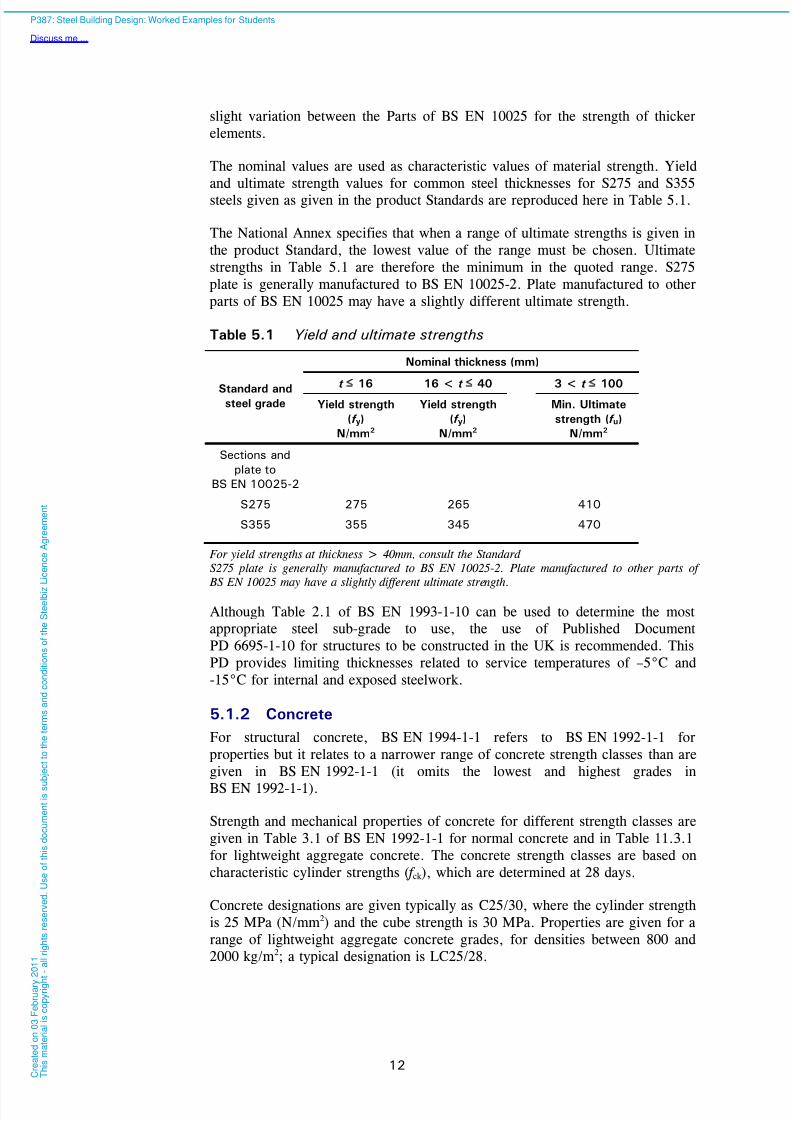
The nominal values are used as characteristic values of material strength. Yield
and ultimate strength values for common steel thicknesses for S275 and S355
steels given as given in the product Standards are reproduced here in Table 5.1.
The National Annex specifies that when a range of ultimate strengths is given in
the product Standard, the lowest value of the range must be chosen. Ultimate
strengths in Table 5.1 are therefore the minimum in the quoted range. S275
plate is generally manufactured to BS EN 10025-2. Plate manufactured to other
parts of BS EN 10025 may have a slightly different ultimate strength.
Table 5.1 Yield and ultimate strengths
Nominal thickness (mm)
t 16 16 < t 40 3 < t 100Standard andsteel grade Yield strength
(f y)
N/mm2
Yield strength
(f y)
N/mm2
Min. Ultimate
strength (f u)
N/mm2
Sections and
plate to
BS EN 10025-2
S275 275 265 410
S355 355 345 470
For yield strengths at thickness > 40mm, consult the Standard
S275 plate is generally manufactured to BS EN 10025-2. Plate manufactured to other parts of
BS EN 10025 may have a slightly different ultimate strength.
Although Table 2.1 of BS EN 1993-1-10 can be used to determine the most
appropriate steel sub-grade to use, the use of Published Document
PD 6695-1-10 for structures to be constructed in the UK is recommended. This
PD provides limiting thicknesses related to service temperatures of –5°C and
-15°C for internal and exposed steelwork.
5.1.2 Concrete
For structural concrete, BS EN 1994-1-1 refers to BS EN 1992-1-1 for
properties but it relates to a narrower range of concrete strength classes than are
given in BS EN 1992-1-1 (it omits the lowest and highest grades in
BS EN 1992-1-1).
Strength and mechanical properties of concrete for different strength classes are
given in Table 3.1 of BS EN 1992-1-1 for normal concrete and in Table 11.3.1
for lightweight aggregate concrete. The concrete strength classes are based on
characteristic cylinder strengths ( f ck ), which are determined at 28 days.
Concrete designations are given typically as C25/30, where the cylinder strength
is 25 MPa (N/mm2) and the cube strength is 30 MPa. Properties are given for a
range of lightweight aggregate concrete grades, for densities between 800 and
2000 kg/m2; a typical designation is LC25/28.
P387: Steel Building Design: Worked Examples for Students
Discuss me ...
C r e a
t e d o n
0 3 F e
b r u a r y
2 0 1 1
T h i s m a
t e r i a
l i s c o p y r i g h
t - a
l l r i g
h t s r e s e r v e
d .
U s e o
f t h i s d o c u m e n
t i s s u
b j e c
t t o t h e
t e r m s a n
d c o n
d i t i o n s o
f t h e
S t e e
l b i z
L i c e n c e
A g r e e m e n
t

8/13/2019 p387 Calcul Imbinari in Engleza
http://slidepdf.com/reader/full/p387-calcul-imbinari-in-engleza 19/105
13
5.1.3 Shear connectors
Properties for headed stud shear connectors should be determined from
EN ISO 13918, which covers a range of stud diameters from 10 mm to 25 mm
and two materials – structural steel and stainless steel. In determining the design
resistance, BS EN 1994-1-1 limits the material ultimate tensile strength to500 N/mm². When specifying headed stud shear connectors, the designation
“SD” is used - for example: “SD 19×100”, which is a stud of 19 mm diameter
and a nominal height of 100 mm.
5.1.4 Reinforcement
BS EN 1994-1-1, Section 3.2 refers to BS EN 1992-1-1 for the properties of
reinforcing steel. However, it should be noted BS EN 1994-1-1 permits the
design value of the modulus of elasticity for reinforcing steel to be taken as
equal to that for structural steel given in BS EN 1993-1-1 (i.e. 210 kN/mm²
rather than 200 kN/mm²).
5.1.5 Profiled steel decking
BS EN 1994-1-1 refers to Sections 3.1 and 3.2 of BS EN 1993-1-3 for the
material properties of profiled steel sheeting.
5.2 Section classification
Four classes of cross section are defined in BS EN 1993. Each part of a section
that is in compression is classified and the class of the whole cross section is
deemed to be the highest (least favourable) class of its compression parts.
Table 5.2 of BS EN 1993-1-1 gives limits for the width to thickness ratios for
the compression parts of a section for each classification.
The section classification in BS EN 1993-1-1 is adopted for composite sections.
Where a steel element is attached to a reinforced concrete element, the
classification of the element can, in some cases, be improved. Requirements for
ductility of reinforcement in tension are given for class 1 and class 2 cross
sections.
5.3 Resistance
Design values of member and connection resistances are determined from
characteristic values of material strength and geometrical properties, divided bya partial factor ( M). Values of M are given in BS EN 1993-1-1 or
BS EN 1994-1-1, as appropriate.
Key values from the National Annexes to BS EN 1993-1-1 and BS EN 1993-1-8
are given below.
Factor Value
M0 (resistance of cross-sections) 1.0
M1 (strength checks of members) 1.0
M2 (resistance of bolts and welds) 1.25
P387: Steel Building Design: Worked Examples for Students
Discuss me ...
C r e a
t e d o n
0 3 F e
b r u a r y
2 0 1 1
T h i s m a
t e r i a
l i s c o p y r i g h
t - a
l l r i g
h t s r e s e r v e
d .
U s e o
f t h i s d o c u m e n
t i s s u
b j e c
t t o t h e
t e r m s a n
d c o n
d i t i o n s o
f t h e
S t e e
l b i z
L i c e n c e
A g r e e m e n
t

8/13/2019 p387 Calcul Imbinari in Engleza
http://slidepdf.com/reader/full/p387-calcul-imbinari-in-engleza 20/105
14
5.3.1 Cross sectional resistance
Steel sections
Expressions for determining the cross sectional resistance in tension,
compression, bending and shear for the four classes of sections are given in
Section 6.2 of BS EN 1993-1-1. The design values of resistance are expressedas N t,Rd, N c,Rd, V c,Rd and M c,Rd respectively.
For slender webs, the shear resistance may be limited by shear buckling; for
such situations, reference is made to BS EN 1993-1-5. Shear buckling is rarely
a consideration with hot rolled sections.
Composite sections
The design bending resistance of a composite section may be determined by
elastic analysis and non-linear theory for any class of cross section; for Class 1
or Class 2 cross-sections, rigid-plastic theory may be used.
Plastic resistance moments of composite sections may be determined either
assuming full interaction between the steel and reinforced concrete or for partial
shear connection (i.e. when the force transferred to the concrete is limited by
the resistance of the shear connectors).
The resistance of a composite section to vertical shear is generally taken simply
as the shear resistance of the structural steel section. Where necessary, the
resistance of uncased webs to shear buckling should be determined in
accordance with BS EN 1993-1-5.
5.3.2 Buckling resistance
Steel sections
Members in compression
BS EN 1993-1-1 presents guidance for checking flexural, torsional and
torsional-flexural buckling for members in compression. The Eurocode requires
flexural buckling resistance to be verified for all members; torsional and
torsional-flexural buckling resistances only need to be verified for members with
open cross sections.
A set of five buckling curves is given in Figure 6.4 of BS EN 1993-1-1. The
buckling curve is selected appropriate to the cross section type and the axis
about which the column buckles. The curves give the value of a reduction factor dependent on the non-dimensional slenderness of the member . The factor is applied as a multiplier to the resistance of the cross section to determine the
buckling resistance of the member.
Generally, for columns using hot rolled I and H sections, torsional or torsional-
flexural buckling will not determine the buckling resistance of the column.
Members in bending
Laterally unrestrained members in bending about their major axes need to be
verified against lateral torsional buckling.
Four buckling curves are defined for lateral torsional buckling, in a similar way
to those for flexural buckling of members in compression, but the curves are not
illustrated in BS EN 1993-1-1. As for flexural buckling, a reduction factor LT
P387: Steel Building Design: Worked Examples for Students
Discuss me ...
C r e a
t e d o n
0 3 F e
b r u a r y
2 0 1 1
T h i s m a
t e r i a
l i s c o p y r i g h
t - a
l l r i g
h t s r e s e r v e
d .
U s e o
f t h i s d o c u m e n
t i s s u
b j e c
t t o t h e
t e r m s a n
d c o n
d i t i o n s o
f t h e
S t e e
l b i z
L i c e n c e
A g r e e m e n
t

8/13/2019 p387 Calcul Imbinari in Engleza
http://slidepdf.com/reader/full/p387-calcul-imbinari-in-engleza 21/105
15
is determined, dependent on the non-dimensional slenderness LT and on the
cross section; the rules are given in clause 6.3.2 of BS EN 1993-1-1.
For uniform members in bending, three approaches are given:
Lateral torsional buckling curves – general case
Lateral torsional buckling curves for rolled sections and equivalent welded
sections
A simplified assessment method for beams in buildings with discrete lateral
restraints to the compression flange.
The second approach gives slightly higher resistances for rolled sections, and is
recommended. The UK National Annex should be considered carefully, as it
modifies the imperfection factors for rolled sections (affecting tall, narrow
beams) and provides specific factors to be used for welded sections.
The guidance given for calculating the beam slenderness for the first two
approaches requires the value of the elastic critical moment for lateral torsional
buckling ( M cr ), but no expressions are given for determining this value.
Therefore, calculation methods need to be obtained from other sources; three
sources are:
A method for calculating beam slenderness for rolled I, H and channel
sections is given in the SCI publication P362 Steel building design: Concise
guide to Eurocode 3.
NCCI for calculating M cr is provided on the Access Steel web site
(www.access-steel.com).
LTbeam; free software from http://www.cticm.eu/spip.php?lang=en
Members in bending and axial compression
For members subject to bending and axial compression the criteria given in
6.3.3 of BS EN 1993-1-1 must be satisfied.
Interaction factors (k ij) used in the checks may be calculated using either method
1 or 2 given respectively in Annexes A and B of BS EN 1993-1-1. The
approach in Annex B is considered to be the simpler of the two methods.
General method for lateral and lateral torsional buckling
The general method given in 6.3.4 of BS EN 1993-1-1 should not be confused
with the general case for lateral torsional buckling given in 6.3.2.2 of
BS EN 1993-1-1.
The general method gives guidance for structural components that are not
covered by the guidance given for compression, bending or bending and axial
compression members, and is not likely to be used by most building designers.
Lateral torsional buckling with plastic hinges
Section 6.3.5 of BS EN 1993-1-1 presents guidance for buildings that are
designed using plastic analysis, such as portal frames.
5.3.3 Shear Connection
Rules for the verification of the shear connection in composite beams are given
in Section 6.6 of BS EN 1994-1-1. Detailed rules are only given for headed stud
P387: Steel Building Design: Worked Examples for Students
Discuss me ...
C r e a
t e d o n
0 3 F e
b r u a r y
2 0 1 1
T h i s m a
t e r i a
l i s c o p y r i g h
t - a
l l r i g
h t s r e s e r v e
d .
U s e o
f t h i s d o c u m e n
t i s s u
b j e c
t t o t h e
t e r m s a n
d c o n
d i t i o n s o
f t h e
S t e e
l b i z
L i c e n c e
A g r e e m e n
t
8/13/2019 p387 Calcul Imbinari in Engleza
http://slidepdf.com/reader/full/p387-calcul-imbinari-in-engleza 22/105
16
connectors. Dimension limits and rules for transverse reinforcement are given.
Natural bond between the concrete and steel is ignored.
BS EN 1994-1-1 gives the design shear resistance of a headed stud connector as
the smaller of the shear resistance of the stud and the crushing strength of the
concrete around it. When used with profiled steel sheeting, a reduction factor,based on the geometry of the deck, the height of the stud and the number of
studs per trough (for decking perpendicular to the beam), is used to reduce the
resistance of the shear connectors.
Limitations are given on the use of partial shear connection, i.e. for situations
where the design shear resistance over a length of beam is insufficient to
develop the full resistance of the concrete slab.
Longitudinal shear resistance of concrete slabs
The longitudinal shear resistance of a slab is calculated using the procedure
given in BS EN 1992-1-1. However, the shear planes that may be critical andthe contributions from the reinforcement or the profiled steel sheeting (if the
shear connectors are through-deck welded) are defined in BS EN 1994-1-1.
5.4 Joints
BS EN 1993-1-8 gives rules for the design of joints between structural
members.
Note that a joint is defined as a zone where two or more members are
interconnected; a connection is the location where elements meet and is thus the
means to transfer forces and moments.
BS EN 1993-1-8 gives guidance for the design of bolted and welded steel
connections subject to predominantly static loading. The steel grades covered
are S235, S275, S355 and S460.
BS EN 1993-1-8 classifies joints according to their rotational stiffness as
nominally pinned, rigid or semi-rigid. The appropriate type of joint model to be
used in global analysis depends on this classification and the method of global
analysis. The Standard notes that joints may be classified on the basis of
experimental evidence, experience of previous satisfactory performance in
similar cases or by calculations based on test evidence. The UK National Annex
advises that connections designed in accordance with the principles given in the
publication Joints in steel construction: Simple connections may be classified as
nominally pinned joints.
5.4.1 Bolted connections
BS EN 1993-1-8 defines five categories of bolted connections. These categories
distinguish between connections loaded in shear or tension, and connections
containing preloaded or non-preloaded bolts. A distinction is also made between
preloaded bolts that have slip resistance at serviceability limit state and slip
resistance at ultimate limit state. Minimum edge and end distances and bolt
spacings are given in terms of the diameter of the bolt hole.
Nominal yield ( f yb) and ultimate tensile ( f ub) strengths are given for a wide rangeof bolt classes in Table 3.1 BS EN 1993-1-8; the nominal values should be
adopted as characteristic values.
P387: Steel Building Design: Worked Examples for Students
Discuss me ...
C r e a
t e d o n
0 3 F e
b r u a r y
2 0 1 1
T h i s m a
t e r i a
l i s c o p y r i g h
t - a
l l r i g
h t s r e s e r v e
d .
U s e o
f t h i s d o c u m e n
t i s s u
b j e c
t t o t h e
t e r m s a n
d c o n
d i t i o n s o
f t h e
S t e e
l b i z
L i c e n c e
A g r e e m e n
t

8/13/2019 p387 Calcul Imbinari in Engleza
http://slidepdf.com/reader/full/p387-calcul-imbinari-in-engleza 23/105
17
5.4.2 Welded connections
BS EN 1993-1-8 gives guidance for the design of the following types of welds:
Fillet welds
Fillet welds all round
Full penetration butt welds
Partial penetration butt welds
Plug welds
Flare groove welds.
Design resistances of fillet and partial penetration welds are expressed in
relation to their throat thickness (rather than leg length) and the ultimate
strength of the material joined.
5.5 Robustness
Connections between building members should be designed so that they prevent
the building from failing in a manner disproportionate to the event that has
caused the structural damage.
BS EN 1991-1-7 gives the design requirements for making structures robust
against accidental actions. The Eurocodes separate buildings into 4 classes, with
different design requirements for each class of structure.
In addition to the requirements given in the Eurocodes, any national
requirements should also be satisfied. In England and Wales, the requirements
for the control of disproportionate collapse are given in Approved Document A
of the Building Regulations. In Scotland the requirements are given in The
Scottish Building Standards, Technical Handbook: Domestic and for Northern
Ireland they are given in The Building Regulations (Northern Ireland),
Technical Booklet D.
5.6 Fire design / protection
Structural steelwork must either be protected or designed in such a way as to
avoid premature failure of the structure when exposed to fire.
Fire protection may be given to structural steelwork members by the use of:
Intumescent paints
Mineral boards
Concrete encasement.
Design guidance for the accidental design situation for fire exposure is given in
BS EN 1993-1-2 for structural steelwork and in BS EN 1994-1-2 for composite
steel and concrete structures.
P387: Steel Building Design: Worked Examples for Students
Discuss me ...
C r e a
t e d o n
0 3 F e
b r u a r y
2 0 1 1
T h i s m a
t e r i a
l i s c o p y r i g h
t - a
l l r i g
h t s r e s e r v e
d .
U s e o
f t h i s d o c u m e n
t i s s u
b j e c
t t o t h e
t e r m s a n
d c o n
d i t i o n s o
f t h e
S t e e
l b i z
L i c e n c e
A g r e e m e n
t
8/13/2019 p387 Calcul Imbinari in Engleza
http://slidepdf.com/reader/full/p387-calcul-imbinari-in-engleza 24/105
18
5.7 Corrosion protection
The main points to be considered during the design process when deciding on
the type of corrosion protection to be applied to the structural steelwork are:
Application of coating – the need to ensure that the chosen coating can beefficiently applied.
Contact with other materials.
Entrapment of moisture and dirt around the steelwork.
Other factors, e.g. provision of suitable access for maintenance and
inspection during the life of the structure.
Types of corrosion protection for structural steelwork members include painted
coatings, hot-dip galvanizing and thermal (metal) spraying. Guidance on
corrosion protection can be found in the Corrosion Protection Guides produced
by Corus.
P387: Steel Building Design: Worked Examples for Students
Discuss me ...
C r e a
t e d o n
0 3 F e
b r u a r y
2 0 1 1
T h i s m a
t e r i a
l i s c o p y r i g h
t - a
l l r i g
h t s r e s e r v e
d .
U s e o
f t h i s d o c u m e n
t i s s u
b j e c
t t o t h e
t e r m s a n
d c o n
d i t i o n s o
f t h e
S t e e
l b i z
L i c e n c e
A g r e e m e n
t
8/13/2019 p387 Calcul Imbinari in Engleza
http://slidepdf.com/reader/full/p387-calcul-imbinari-in-engleza 25/105
19
6 WORKED EXAMPLES
The set of worked examples in this Section present the design of structural
elements that may be found in a braced steel frame building.
The following should be noted when using the worked examples:
The structural arrangements used in the notional building considered in this
publication are not typical of building design. This is because the structural
solutions have been chosen to demonstrate a range of design situations.
Within the examples, UK National Annex values have been used. For
construction in other countries, the appropriate National Annexes should be
consulted.
Combination of actions – the examples generally use the least favourable
value obtained from either expression (6.10a) or (6.10b) of BS EN 1990,
and usually (6.10b), since this is generally the least favourable in orthodox
construction.
The worked examples contained in this Section are:
Page
00 Structural layout and Actions 21
01 Simply supported restrained beam 23
02 Simply supported unrestrained beam 29
03 Simply supported composite beam 35
04 Edge beam 45
05 Column in simple construction 51
06 Roof truss 55
07 Choosing a steel sub-grade 61
08 Slab design 63
09 Bracing and bracing connections 71
10 Beam-to-column flexible end plate
connection
83
11 Column base connection 91
12 Frame stability 93
P387: Steel Building Design: Worked Examples for Students
Discuss me ...
C r e a
t e d o n
0 3 F e
b r u a r y
2 0 1 1
T h i s m a
t e r i a
l i s c o p y r i g h
t - a
l l r i g
h t s r e s e r v e
d .
U s e o
f t h i s d o c u m e n
t i s s u
b j e c
t t o t h e
t e r m s a n
d c o n
d i t i o n s o
f t h e
S t e e
l b i z
L i c e n c e
A g r e e m e n
t

8/13/2019 p387 Calcul Imbinari in Engleza
http://slidepdf.com/reader/full/p387-calcul-imbinari-in-engleza 26/105
20
P387: Steel Building Design: Worked Examples for Students
Discuss me ...
C r e a
t e d o n
0 3 F e
b r u a r y
2 0 1 1
T h i s m a
t e r i a
l i s c o p y r i g h
t - a
l l r i g
h t s r e s e r v e
d .
U s e o
f t h i s d o c u m e n
t i s s u
b j e c
t t o t h e
t e r m s a n
d c o n
d i t i o n s o
f t h e
S t e e
l b i z
L i c e n c e
A g r e e m e n
t

8/13/2019 p387 Calcul Imbinari in Engleza
http://slidepdf.com/reader/full/p387-calcul-imbinari-in-engleza 27/105
Job No. Sheet of 2 Rev C
Job Title Example No. 00 Revised by DGB, April 09
Subject Structural layout and actions
Made by MEB Date Sept 2006
Silwood Park, Ascot, Berks SL5 7QN
Telephone: (01344) 636525
Fax: (01344) 636570
CALCULATION SHEET
Client
Checked by DGB Date Jan 2008
21
Unless stated
otherwise all
references are
to BS EN
1991-1-
1:2002
Structural layout and actions
The various structural arrangements used in the notional building
considered in this publication are not typical of building design.
This is because the structural solutions have been chosen to
demonstrate a range of design situations.
This example defines the characteristic values of the actions that act
on the building shown in Figure 0.1.
Characteristic actions – Floors above ground level
Permanent actions
Self weight of floor 3.5 kN/m2
Self weight of ceiling, raised floor & services 0.2 kN/m2
Total permanent action is
g k = 3.5 + 0.2 = 3.7 kN/m2
Permanent action,
g k = 3.7 kN/m2
Variable actions
Imposed floor load for offices (category B1) 2.5 kN/m2 Imposed floor load for moveable partitions
of less than 2 kN/m run 0.8 kN/m2
NA2.4 Table NA.2
Table NA.3
6.3.1.2(8) Total variable action is
q k = 2.5 + 0.8 = 3.3 kN/m2
Variable action,
q k = 3.3 kN/m2
Imposed roof actions
Permanent actions
Self weight of roof construction 0.75 kN/m2
Self weight of ceiling and services 0.15 kN/m2
Total permanent action is
g k = 0.75 + 0.15 = 0.9 kN/m2
Roof Permanent
action,
g k = 0.9 kN/m2
Variable actions
NA 2.10
Table NA.7
The roof is only accessible for normal maintenance and repair
Imposed roof load 0.6 kN/m2
The imposed roof load due to snow obtained from EN 1991-1-3 is
less than 0.6 kN/m2, therefore the characteristic imposed roof load
is taken from EN 1991-1-1.
Roof Variable
action,
q k
= 0.6 kN/m2
P387: Steel Building Design: Worked Examples for Students
Discuss me ...
C r e a
t e d o n
0 3 F e
b r u a r y
2 0 1 1
T h i s m a
t e r i a
l i s c o p y r i g h
t - a
l l r i g
h t s r e s e r v e
d .
U s e o
f t h i s d o c u m e n
t i s s u
b j e c
t t o t h e
t e r m s a n
d c o n
d i t i o n s o
f t h e
S t e e
l b i z
L i c e n c e
A g r e e m e n
t

8/13/2019 p387 Calcul Imbinari in Engleza
http://slidepdf.com/reader/full/p387-calcul-imbinari-in-engleza 28/105
Example 00 Structural layout and actions Sheet 2 of 2 Rev
22
The wind load considered here is only for one direction. Other directions must be considered during the design
process. Calculation of the wind loading according to EN 1991-1-4 has not been considered in this example.
Wind action
BS EN
1991-1-4
The total wind force acting on the length of the building (i.e.
perpendicular to the ridge) is
F w = 925 kN
Wind force acting
on the length of the
building is:
F w
= 925 kN
1 2 3
A
B
C
Stairwell
D
E
F
G
H
J
Liftshaft
Wind
direction
Plan at level 1
Precastfloorunits
1 2 3
A
B
C
Stairwell
D
E
F
G
H
J
Liftshaft
AA
Wind
direction
Typical plan
Insitucompositefloor
1
Ground
Roof
3
2
A - A
Typical section
Typical braced bay
Secondarybeam
Secondarybeam
Secondarybeam
Secondarybeam
Secondarybeam
Secondarybeam
Secondarybeam
Secondarybeam
Secondarybeam
Secondarybeam
Secondarybeam
Secondarybeam
Secondarybeam
Secondarybeam
8 m 6 m
14 m
6 m
6 m
6 m
6 m
6 m
6 m
6 m
6 m
48 m
6 m
6 m
6 m
6 m
6 m
6 m
6 m
6 m
8 m 6 m
14 m
48 m
4.5 m
4.5 m
4.5 m
5 m
8 m 6 m
4.5 m
4.5 m
4.5 m
5 m
6 m
Figure 0.1 Building arrangement
P387: Steel Building Design: Worked Examples for Students
Discuss me ...
C r e a
t e d o n
0 3 F e
b r u a r y
2 0 1 1
T h i s m a
t e r i a
l i s c o p y r i g h
t - a
l l r i g
h t s r e s e r v e
d .
U s e o
f t h i s d o c u m e n
t i s s u
b j e c
t t o t h e
t e r m s a n
d c o n
d i t i o n s o
f t h e
S t e e
l b i z
L i c e n c e
A g r e e m e n
t
8/13/2019 p387 Calcul Imbinari in Engleza
http://slidepdf.com/reader/full/p387-calcul-imbinari-in-engleza 29/105
Job No. Sheet of 5 Rev C
Job Title Example no. 01 Revised by DGB, April 09
Subject Simply supported fully restrained beam
Made by DL Date Nov 2006
Silwood Park, Ascot, Berks SL5 7QN
Telephone: (01344) 636525
Fax: (01344) 636570
CALCULATION SHEET
Client
Checked by JTM Date Dec 2006
23
Unless stated
otherwise all
references are
to BS EN
1993-1-
1:2005
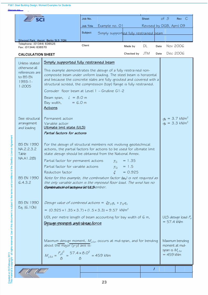
Simply supported fully restrained beam
This example demonstrates the design of a fully restrained non-
composite beam under uniform loading. The steel beam is horizontal
and because the concrete slabs are fully grouted and covered with a
structural screed, the compression (top) flange is fully restrained.
Consider floor beam at Level 1 – Gridline G1-2
Beam span, L = 8.0 m
Bay width, = 6.0 m
Actions
See structural
arrangement
and loading
Permanent action
Variable action
g k = 3.7 kN/m2
q k = 3.3 kN/m2
Ultimate limit state ULS)
Partial factors for actions
BS EN 1990
NA.2.2.3.2
TableNA.A1.2(B)
For the design of structural members not involving geotechnical
actions, the partial factors for actions to be used for ultimate limit
state design should be obtained from the National Annex.Partial factor for permanent actions G = 1.35
Partial factor for variable actions Q = 1.5
Reduction factor = 0.925
BS EN 1990
6.4.3.2
Note for this example, the combination factor ( ψ 0 ) is not required as
the only variable action is the imposed floor load. The wind has no
impact on the design of this member.
Combination of actions at ULS
BS EN 1990
Eq. (6.10b)
Design value of combined actions = k q g Qk G
= 57.9)3.35.1()7.335.1925.0( kN/m2
UDL per metre length of beam accounting for bay width of 6 m,
4.570.657.9d F kN/m
ULS design load F d
= 57.4 kN/m
Design moment and shear force
Maximum design moment, M y,Ed, occurs at mid-span, and for bending
about the major ( y - y ) axis is:
4598
0.84.57
8
22d
Edy,
L F
M kNm
Maximum bending
moment at mid-
span is M y, Ed
= 459 kNm
P387: Steel Building Design: Worked Examples for Students
Discuss me ...
C r e a
t e d o n
0 3 F e
b r u a r y
2 0 1 1
T h i s m a
t e r i a
l i s c o p y r i g h
t - a
l l r i g
h t s r e s e r v e
d .
U s e o
f t h i s d o c u m e n
t i s s u b
j e c
t t o t h e
t e r m s a n
d c o n
d i t i o n s o
f t h e
S t e e
l b i z L i c e n c e
A g r e e m e n
t

8/13/2019 p387 Calcul Imbinari in Engleza
http://slidepdf.com/reader/full/p387-calcul-imbinari-in-engleza 30/105
Example 01 Simply supported fully restrained beam Sheet 2 of 5 Rev
24
Maximum design shear force, V Ed, occurs at the end supports, and
is:
2302
84.57
2d
Ed
L F
V kN
Maximum vertical
shear force at
supports is
V Ed = 230 kN
Partial factors for resistance
6.1(1)
NA 2.15M0 = 1.0
Trial section
NA 2.4
BS EN
10025-2
Table 7
An Advance UK Beam (UKB) S275 is to be used. Assuming the
nominal thickness (t) of the flange and web is less than or equal to
16 mm, the yield strength is:
f y = 275 N/mm2
Yield strength isf y = 275 N/mm2
The required section needs to have a plastic modulus about the
major-axis ( y - y ) that is greater than:
W pl,y =275
0.110459 3
y
M0Edy,
f
M = 1669 cm3.
From the tables of section properties try section 457 191 82
UKB, S275, which has W pl,y = 1830 cm3
z
z
y y
f
w
b
h d
r
t
t
P363 Section 457 191 82 UKB has the following dimensions and
properties
Depth of cross-section h = 460.0 mm
Web depth h w = 428.0 mm
(h w = h – 2t f)Width of cross-section b = 191.3 mm
Depth between fillets d =407.6 mm
Web thickness t w = 9.9 mm
Flange thickness t f = 16.0 mm
Radius of root fillet r = 10.2 mm
Cross-sectional area A = 104 cm2
Second moment of area ( y - y ) I y = 37100 cm4
Second moment of area (z -z ) I z = 1870 cm4
Elastic section modulus ( y - y ) W el,y = 1610 cm3
Plastic section modulus ( y - y ) W pl,y = 1830 cm3
3.2.6(1) Modulus of elasticity E = 210000 N/mm2
P387: Steel Building Design: Worked Examples for Students
Discuss me ...
C r e a
t e d o n
0 3 F e
b r u a r y
2 0 1 1
T h i s m a
t e r i a
l i s c o p y r i g h
t - a
l l r i g
h t s r e s e r v e
d .
U s e o
f t h i s d o c u m e n
t i s s u
b j e c
t t o t h e
t e r m s a n
d c o n
d i t i o n s o
f t h e
S t e e
l b i z
L i c e n c e
A g r e e m e n
t

8/13/2019 p387 Calcul Imbinari in Engleza
http://slidepdf.com/reader/full/p387-calcul-imbinari-in-engleza 31/105
Example 01 Simply supported fully restrained beam Sheet 3 of 5 Rev
25
5.5 & Table
5.2
Classification of cross-section
For section classification the coefficient e is:
92.0275
235235
y
f
Outstand flange: flange under uniform compression
c =
2
2-- w r t b =
2
2.1029.93.191 = 80.5 mm
ft
c =
0.16
5.80 = 5.03
The limiting value for Class 1 is 28.892.099 ≤t
c
5.03 < 8.28
Therefore, the flange outstand in compression is Class 1.
Internal compression part: web under pure bending
c = d = 407.6 mm
wt
c =
9.9
6.407 = 41.17
The limiting value for Class 1 is 24.6692.07272 ≤t
c
41.17 < 66.24
Therefore, the web in pure bending is Class 1.
Therefore the section is Class 1 under pure bending. Section is Class 1
Member resistance verification
6.2.6 Shear resistance
6.2.6(1)
6.2.6(2)
The basic design requirement is:
0.1Rdc,
Ed V
V
V c,Rd =V pl,Rd = M0
yv 3 /
f A (for Class 1 sections)
6.2.6(3) For a rolled I-section with shear parallel to the web the shear area is
fwfv 22 t r t bt AA but not less than h w t w
Av = 104 102 – (2 191.3 16.0)+ (9.9+2 10.2) 16
= 4763 mm2
= 1.0 (conservative)
h w t w = 1.0 428.0 9.9 = 4237 mm2
4763 mm2
> 4237 mm2
Therefore, Av = 4763 mm2
P387: Steel Building Design: Worked Examples for Students
Discuss me ...
C r e a
t e d o n
0 3 F e
b r u a r y
2 0 1 1
T h i s m a
t e r i a
l i s c o p y r i g h
t - a
l l r i g
h t s r e s e r v e
d .
U s e o
f t h i s d o c u m e n
t i s s u
b j e c
t t o t h e
t e r m s a n
d c o n
d i t i o n s o
f t h e
S t e e
l b i z
L i c e n c e
A g r e e m e n
t
8/13/2019 p387 Calcul Imbinari in Engleza
http://slidepdf.com/reader/full/p387-calcul-imbinari-in-engleza 32/105
Example 01 Simply supported fully restrained beam Sheet 4 of 5 Rev
26
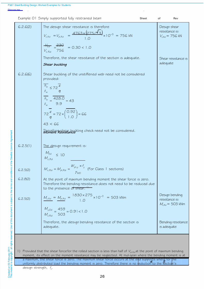
6.2.6(2) The design shear resistance is therefore
V c,Rd =V pl,Rd = 3100.1
3 /2754763
= 756 kN
Design shear
resistance is:
V c,Rd= 756 kN
756
230
c.Rd
Ed V
V = 0.30 1.0
Therefore, the shear resistance of the section is adequate. Shear resistance is
adequate
Shear buckling
6.2.6(6) Shear buckling of the unstiffened web need not be considered
provided:
72
w
w t
h
439.9
0.428
w
w
t
h
660.1
92.07272
43 < 66
Therefore shear buckling check need not be considered.
Moment Resistance
6.2.5(1) The design requirement is:
01c,Rd
Ed .M
M
6.2.5(2) M0
yypl,
pl,Rdc,Rd
f W M M
(For Class 1 sections)
6.2.8(2) At the point of maximum bending moment the shear force is zero.
Therefore the bending resistance does not need to be reduced due
to the presence of shear. 1)
6.2.5(2) M c,Rd = M pl,Rd = 310
0.1
2751830
= 503 kNmDesign bending
resistance is:
M c,Rd= 503 kNm
0.191.0503
459
Rdc,
Edy,
M
M
Therefore, the design bending resistance of the section is
adequate.
Bending resistance
is adequate
1)
Provided that the shear force for the rolled section is less than half of V pl.Rd at the point of maximum bendingmoment, its effect on the moment resistance may be neglected. At mid-span where the bending moment is at
a maximum, the shear force is zero. The maximum shear force occurs at the end supports where for the
uniformly distributed load the bending moment is zero. Therefore there is no reduction to the section’sdesign strength, f y.
P387: Steel Building Design: Worked Examples for Students
Discuss me ...
C r e a
t e d o n
0 3 F e
b r u a r y
2 0 1 1
T h i s m a
t e r i a
l i s c o p y r i g h
t - a
l l r i g
h t s r e s e r v e
d .
U s e o
f t h i s d o c u m e n
t i s s u
b j e c
t t o t h e
t e r m s a n
d c o n
d i t i o n s o
f t h e
S t e e
l b i z
L i c e n c e
A g r e e m e n
t

8/13/2019 p387 Calcul Imbinari in Engleza
http://slidepdf.com/reader/full/p387-calcul-imbinari-in-engleza 33/105
Example 01 Simply supported fully restrained beam Sheet 5 of 5 Rev
27
Serviceability Limit State SLS)
BS EN 1990
NA 2.2.6
Guidance on deflection limits and combinations of actions to be
considered are given in the material Standards.
BS EN
1993-1-1NA 2.23
Vertical deflections should normally be calculated under the
characteristic load combination due to variable loads. Permanentloads should not be included.
BS EN1990
6.5.3
(6.14b)
The characteristic load combination at SLS is:
i k i k k Q Q G ,,01, ∑++∑
This is modified by NA 2.23 to EN 1993-1-1 which states that
permanent loads should not be included. As there is only one
variable action present, the term i k i Q ,,0 ∑ = 0
Vertical deflection of beam
The vertical deflection at the mid-span is determined as:
w =y
k 4
384
5
EI
q L
8.190.63.3k q kN/m
w = 6.13=10×37100×210000×384
8.19×8000×54
4
mmVertical mid-span
deflection
w = 13.6 mm
BS EN
1993-1-1
NA 2.23
Vertical deflection limit for this example is
2.22360
8000
360
Span
mm
13.6 mm < 22.2 mm
Therefore, the vertical deflection of the section is satisfactory. Vertical deflection
is acceptable
Adopt 457 191 82 UKB in S275 steel
Dynamics
Generally, a check of the dynamic response of a floor beam would be
required at SLS. These calculations are not shown here.
P387: Steel Building Design: Worked Examples for Students
Discuss me ...
C r e a
t e d o n
0 3 F e
b r u a r y
2 0 1 1
T h i s m a
t e r i a
l i s c o p y r i g h
t - a
l l r i g
h t s r e s e r v e
d .
U s e o
f t h i s d o c u m e n
t i s s u
b j e c
t t o t h e
t e r m s a n
d c o n
d i t i o n s o
f t h e
S t e e
l b i z
L i c e n c e
A g r e e m e n
t

8/13/2019 p387 Calcul Imbinari in Engleza
http://slidepdf.com/reader/full/p387-calcul-imbinari-in-engleza 34/105
28
P387: Steel Building Design: Worked Examples for Students
Discuss me ...
C r e a
t e d o n
0 3 F e
b r u a r y
2 0 1 1
T h i s m a
t e r i a
l i s c o p y r i g h
t - a
l l r i g
h t s r e s e r v e
d .
U s e o
f t h i s d o c u m e n
t i s s u
b j e c
t t o t h e
t e r m s a n
d c o n
d i t i o n s o
f t h e
S t e e
l b i z
L i c e n c e
A g r e e m e n
t
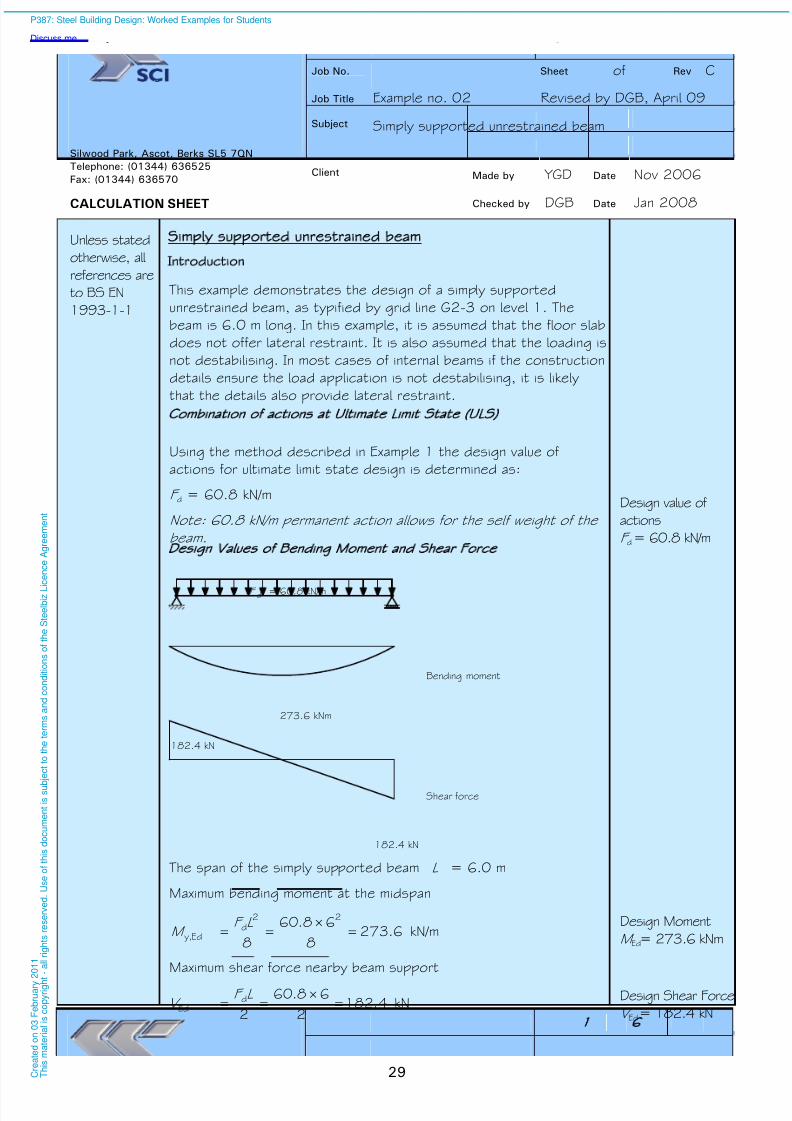
8/13/2019 p387 Calcul Imbinari in Engleza
http://slidepdf.com/reader/full/p387-calcul-imbinari-in-engleza 35/105
Job No. Sheet 1 of 6 Rev C
Job Title Example no. 02 Revised by DGB, April 09
Subject Simply supported unrestrained beam
Made by YGD Date Nov 2006
Silwood Park, Ascot, Berks SL5 7QN
Telephone: (01344) 636525
Fax: (01344) 636570
CALCULATION SHEET
Client
Checked by DGB Date Jan 2008
29
Simply supported unrestrained beam
ntroduction
Unless stated
otherwise, all
references are
to BS EN
1993-1-1
This example demonstrates the design of a simply supported
unrestrained beam, as typified by grid line G2-3 on level 1. The
beam is 6.0 m long. In this example, it is assumed that the floor slab
does not offer lateral restraint. It is also assumed that the loading is
not destabilising. In most cases of internal beams if the construction
details ensure the load application is not destabilising, it is likely
that the details also provide lateral restraint.
Combination of actions at Ultimate Limit State ULS)
Using the method described in Example 1 the design value of
actions for ultimate limit state design is determined as:
F d = 60.8 kN/m
Note: 60.8 kN/m permanent action allows for the self weight of the
beam.
Design value of
actions
F d= 60.8 kN/m
Design Values of Bending Moment and Shear Force
= 60.8 kN/mF d
Bending moment
Shear force
182.4 kN
273.6 kNm
182.4 kN
The span of the simply supported beam L = 6.0 m
Maximum bending moment at the midspan
6.2738
68.60
8
22d
Edy,
L F M kN/m
Design Moment
M Ed= 273.6 kNm
Maximum shear force nearby beam support
4.1822
68.60
2d
Ed
L F V kN
Design Shear Force
V Ed= 182.4 kN
P387: Steel Building Design: Worked Examples for Students
Discuss me ...
C r e a
t e d o n
0 3 F e
b r u a r y
2 0 1 1
T h i s m a
t e r i a
l i s c o p y r i g h
t - a
l l r i g
h t s r e s e r v e
d .
U s e o
f t h i s d o c u m e n
t i s s u b
j e c
t t o t h e
t e r m s a n
d c o n
d i t i o n s o
f t h e
S t e e
l b i z L i c e n c e
A g r e e m e n
t
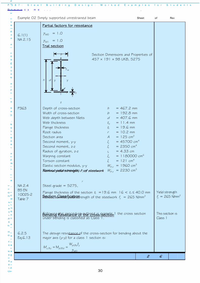
8/13/2019 p387 Calcul Imbinari in Engleza
http://slidepdf.com/reader/full/p387-calcul-imbinari-in-engleza 36/105
Example 02 Simply supported unrestrained beam Sheet 2 of 6 Rev
30
6.1(1)
NA 2.15
Partial factors for resistance
M0 = 1.0
M1 = 1.0
Trial section
z
z
y y
f
w
b
h d
r
t
t
Section Dimensions and Properties of
457 191 98 UKB, S275
P363 Depth of cross-section h = 467.2 mm
Width of cross-section b = 192.8 mm
Web depth between fillets d = 407.6 mm
Web thickness t w = 11.4 mm
Flange thickness t f = 19.6 mm
Root radius r = 10.2 mm
Section area A = 125 cm2
Second moment, y-y I y = 45700 cm4
Second moment, z-z I
z = 2350 cm
4
Radius of gyration, z-z i z = 4.33 cm
Warping constant I w = 1180000 cm6
Torsion constant I t = 121 cm4
Elastic section modulus, y-y W el,y = 1960 cm3
Plastic section modulus, y-y W pl,y = 2230 cm3
Nominal yield strength f y of steelwork
NA 2.4
BS EN
10025-2
Table 7
Steel grade = S275,
Flange thickness of the section t f =19.6 mm 16 < t f 40.0 mm
Hence, nominal yield strength of the steelwork f y = 265 N/mm2
Yield strength
f y = 265 N/mm2
Section Classification
Following the procedure outlined in example 1 the cross section
under bending is classified as Class 1.
This section is
Class 1
Bending Resistance of the cross-section
6.2.5
Eq.6.13
The design resistance of the cross-section for bending about the
major axis ( y - y ) for a class 1 section is:
Rdc,M M0
yRdpl,
Rdpl,
fW
M
P 3 8 7 : S t e e l B u i l d i n g D e s i g n : W o r k e d E x a m p l e s f o r S t u d e n t s
D i s c u s s m e . . .
C
r
e
a
t
e
d
o
n
0
3
F
e
b
r
u
a
r
y
2
0
1
1
T
h
i
s
m
a
t
e
r
i
a
l
i
s
c
o
p
y
r
i
g
h
t
-
a
l
l
r
i
g
h
t
s
r
e
s
e
r
v
e
d
.
U
s
e
o f
t
h
i
s
d
o
c
u
m
e
n
t
i
s
s
u
b
j
e
c
t
t
o
t
h

8/13/2019 p387 Calcul Imbinari in Engleza
http://slidepdf.com/reader/full/p387-calcul-imbinari-in-engleza 37/105
Example 02 Simply supported unrestrained beam Sheet 3 of 6 Rev
31
591100.1
265102230 63
kNmDesign Bending
Resistance
M c,Rd=591 kNm
6.2.5
Eq.6.1200.146.0
591
6.273
Rdc,
Ed M
M OK
Lateral torsional buckling resistance
Non-dimensional slenderness of an unrestrained beam
6.3.2.2(1) LT cr
yy
M
f W
As BS EN 1993-1-1 does not include an expression for determining
M cr an alternative (conservative) method for determining LT is used
here.1)
P 362 Expn(6.55) wz
1
LT 9.01 C
P 362 Table
5.5
For a simply supported beam with a uniform distributed load,
94.01
1
C
zz
i
L
L = 6000 mm 2)
6.1383.43
6000
zz
i L
6.3.1.3 265
210000 π π
y
f
E =88.4
568.14.88
1
3.43
60001
1z
z
i
L
For Class 1 and 2 sections, 0.1ypl,
ypl,
ypl,
y
w W
W
W
W
Hence, non-dimensional slenderness
33.10.1568.190.094.09.01
wz
1
LT C
slenderness
33.1LT
1) The calculation of the elastic critical moment (M cr) and thus a less conservative value of LT is given at the
end of this example.
2) Conservatively, for a simply supported beam, take the buckling length to equal the span length.
P387: Steel Building Design: Worked Examples for Students
Discuss me ...
C r e a
t e d o n
0 3 F e
b r u a r y
2 0 1 1
T h i s m a
t e r i a
l i s c o p y r i g h
t - a
l l r i g
h t s r e s e r v e
d .
U s e o
f t h i s d o c u m e n
t i s s u
b j e c
t t o t h e
t e r m s a n
d c o n
d i t i o n s o
f t h e
S t e e
l b i z
L i c e n c e
A g r e e m e n
t
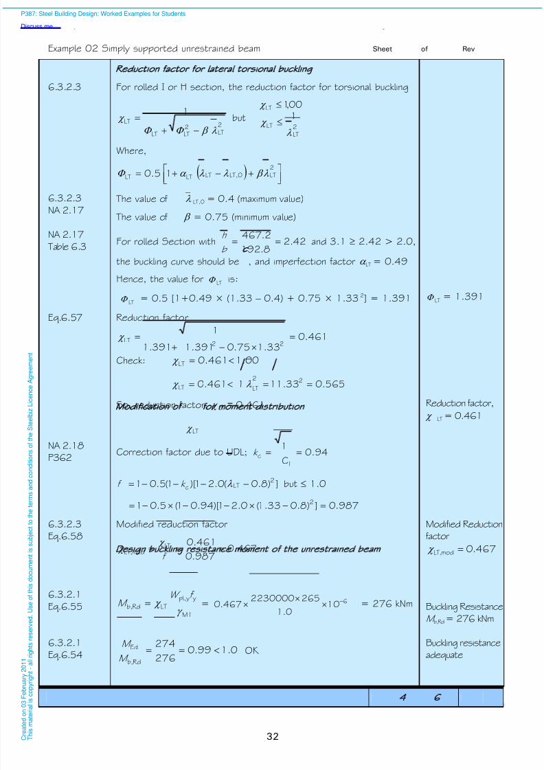
8/13/2019 p387 Calcul Imbinari in Engleza
http://slidepdf.com/reader/full/p387-calcul-imbinari-in-engleza 38/105
Example 02 Simply supported unrestrained beam Sheet 4 of 6 Rev
32
Reduction factor for lateral torsional buckling
6.3.2.3 For rolled I or H section, the reduction factor for torsional buckling
2
LT
2
LTLT
LT
1
but2
LT
LT
LT
100,1
Where,
2LTLT,0LTLTLT 10.5
6.3.2.3
NA 2.17 The value of LT,0 = 0.4 (maximum value)
The value of = 0.75 (minimum value)
NA 2.17
Table 6.3For rolled Section with 42.2
8.192
2.467
b
h and 3.1 2.42 > 2.0,
the buckling curve should be c, and imperfection factor LT = 0.49
Hence, the value for LT is:
LT = 0.5 [1+0.49 × (1.33 – 0.4) + 0.75 × 1.332] = 1.391 LT = 1.391
Eq.6.57 Reduction factor
461.033.175.0391.1391.1
1
22LT
Check: 00.1461.0LT
461.0LT 565.033.111 22
LT
So, reduction factor, LT = 0.461 Reduction factor, LT = 0.461
Modification of LT for moment distribution
NA 2.18
P362Correction factor due to UDL; 94.0
C
1
1
c k
])8.0(0.21)[1(5.01 2LTc k f but 1.0
987.0])8.033.1(0.21)[94.01(5.01 2
6.3.2.3
Eq.6.58
Modified reduction factor
467.0987.0
461.0LTmodLT,
f
Modified Reduction
factor467.0mod,LT
Design buckling resistance moment of the unrestrained beam
6.3.2.1
Eq.6.55M1
yypl,
LTRdb,
f W
M = 6100.1
2652230000467.0
= 276 kNm Buckling Resistance
M b,Rd= 276 kNm
6.3.2.1
Eq.6.540.199.0
276
274
Rdb,
Ed M
M OK
Buckling resistance
adequate
P387: Steel Building Design: Worked Examples for Students
Discuss me ...
C r e a
t e d o n
0 3 F e
b r u a r y
2 0 1 1
T h i s m a
t e r i a
l i s c o p y r i g h
t - a
l l r i g
h t s r e s e r v e
d .
U s e o
f t h i s d o c u m e n
t i s s u b
j e c
t t o t h e
t e r m s a n
d c o n
d i t i o n s o
f t h e
S t e e
l b i z L i c e n c e
A g r e e m e n
t

8/13/2019 p387 Calcul Imbinari in Engleza
http://slidepdf.com/reader/full/p387-calcul-imbinari-in-engleza 39/105
Example 02 Simply supported unrestrained beam Sheet 5 of 6 Rev
33
Shear Resistance
6.2.6.3 The shear resistance calculation process is identical to example 1,
and is not repeated here.
The calculated shear resistance, V c,Rd = 852 kN, > 182 kN, OK
Adopt 457 191 98 UKB in S275
Calculation of the elastic critical moment Mcr)
Access-steel
document
SN003a-EN-EU
For doubly symmetric sections, M cr may be determined from:
g2
2g2
z2
t2
z
w
2
w2z
2
1cr )()(
)(z C z C
EI
GI kL
I
I
k
k
kL
EI C M
3.2.6(1)
SN003a
Table 3.2
Where:
Modulus of elasticity E = 2100000 N/mm2
Shear Modulus G = 81000 N/mm2
Distance between lateral supports L = 6000 mm
No device to prevent beam end
from warping
k w = 1
Compression flange free to rotate
about z-z
k = 1
For uniformly distributed load on a
simply supported beam
C 1 = 1.127, and
C 2 = 0.454
z g is the distance from the load application to the shear centre ofthe member. When loads applied above the shear centre are
destabilising, z g is positive. Loads applied below the shear centre are
not destabilising, and z g is negative. If loads are not destabilising (as
this example), it is conservative to take z g as zero. When k w and
k = 1, and z g = zero, the expression for M cr becomes:
z
2t
2
z
w
2z
2
1crEI
GI L
I
I
L
EI C M
kN1353106000
23500000210000
32
2
2
z2
L
EI
2
z
w cm1.5022350
1180000
I
I
29t kNm01.9810121000081000
GI
1353
01.9805021.01353127.1crM
M cr = 534.0 kNm 0.534cr M kNm
6.3.2.2
Eq.6.56
Hence, Non-dimensional slenderness
07.1100.534
27522300006
cr
yypl,LT
M
f W
Slenderness
07.1LT
P387: Steel Building Design: Worked Examples for Students
Discuss me ...
C r e a
t e d o n
0 3 F e
b r u a r y
2 0 1 1
T h i s m a
t e r i a
l i s c o p y r i g h
t - a
l l r i g
h t s r e s e r v e
d .
U s e o
f t h i s d o c u m e n
t i s s u
b j e c
t t o t h e
t e r m s a n
d c o n
d i t i o n s o
f t h e
S t e e
l b i z
L i c e n c e
A g r e e m e n
t
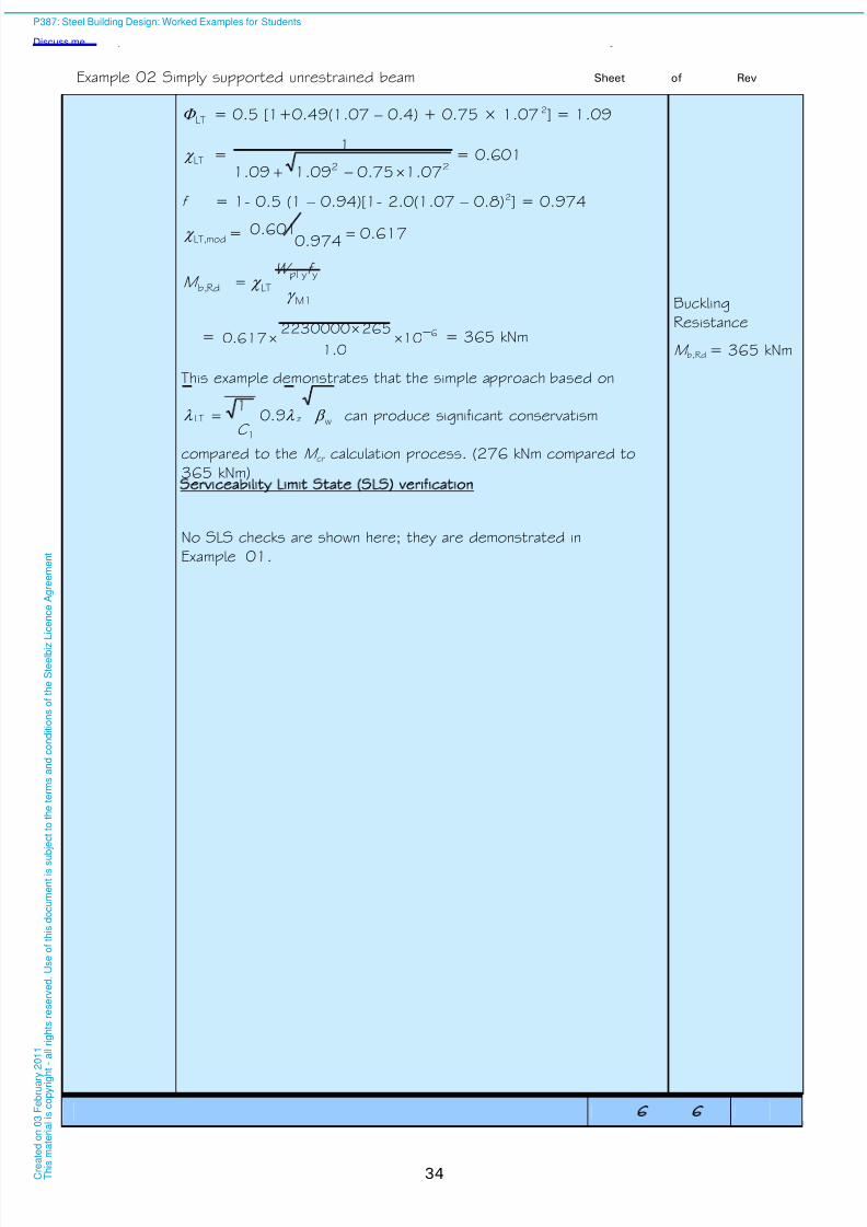
8/13/2019 p387 Calcul Imbinari in Engleza
http://slidepdf.com/reader/full/p387-calcul-imbinari-in-engleza 40/105
Example 02 Simply supported unrestrained beam Sheet 6 of 6 Rev
34
LT = 0.5 [1+0.49(1.07 – 0.4) + 0.75 × 1.072] = 1.09
LT =22 07.175.009.109.1
1
= 0.601
f = 1- 0.5 (1 – 0.94)[1- 2.0(1.07 – 0.8)2] = 0.974
modLT, = 617.0974.0
601.0
M1
yy,pl
LTRdb,
f W
M
= 6100.1
2652230000617.0
= 365 kNm
Buckling
Resistance
M b,Rd = 365 kNm
This example demonstrates that the simple approach based on
wz
1
LT 9.01
C
can produce significant conservatism
compared to the M cr calculation process. (276 kNm compared to
365 kNm)
Serviceability Limit State SLS) verification
No SLS checks are shown here; they are demonstrated in
Example 01.
P387: Steel Building Design: Worked Examples for Students
Discuss me ...
C r e a
t e d o n
0 3 F e
b r u a r y
2 0 1 1
T h i s m a
t e r i a
l i s c o p y r i g h
t - a
l l r i g
h t s r e s e r v e
d .
U s e o
f t h i s d o c u m e n
t i s s u
b j e c
t t o t h e
t e r m s a n
d c o n
d i t i o n s o
f t h e
S t e e
l b i z
L i c e n c e
A g r e e m e n
t

8/13/2019 p387 Calcul Imbinari in Engleza
http://slidepdf.com/reader/full/p387-calcul-imbinari-in-engleza 41/105
Job No. Sheet 1 of 1 Rev C
Job Title Example no. 03 Revised by DGB, April 09
Subject Simply supported composite secondary beam
Made by BK Date Nov 07
Silwood Park, Ascot, Berks SL5 7QN
Telephone: (01344) 636525
Fax: (01344) 636570
CALCULATION SHEET
Client
Checked by WT Date Dec 07
35
Unless stated
otherwise all
references are
to BS EN
1994-1-1
Simply supported composite secondary beam
This example shows the design of a 6 m long composite beam
subject to UDL, at 3 m centres. The composite slab is 130 mm
deep with 1.0 mm gauge ComFlor 60 (Corus) running perpendicular
to the steel beam. The design checks include the moment resistance
of the composite beam, the number of shear connectors, vertical
shear and transverse reinforcement.
See “Structural
arrangementand loading”
Consider the secondary composite beam between and CD on
the typical floor.
60
300
120 180
Dimensions of ComFlor 60 (Corus)
Design data
Beam span L = 6.0 m
Beam spacing s = 3.0 m
Total slab depth h = 130 mm
Depth of concrete above profile h c = 70 mm
Deck profile height h p = 60 mm
Width of the bottom of the trough b bot = 120 mm
Width of the top of the trough b top = 170 mm approx
Shear connectors
Diameter d = 19 mm
Overall height before welding h sc = 100 mm
Height after welding 95mm
BS EN
1993-1-1
NA 2.4
BS EN
10025-2
Table 7
Materials
Structural Steel:
For grade S275 and maximum thickness (t ) less than 16 mm
Yield strength f y = 275 N/mm2
Ultimate strength f u = 410 N/mm2
BS EN1992-1-1
Table C.1
BS 4449
Steel reinforcement: Yield strength f yk = 500 N/mm2
P387: Steel Building Design: Worked Examples for Students
Discuss me ...
C r e a
t e d o n
0 3 F e
b r u a r y
2 0 1 1
T h i s m a
t e r i a
l i s c o p y r i g h
t - a
l l r i g
h t s r e s e r v e
d .
U s e o
f t h i s d o c u m e n
t i s s u
b j e c
t t o t h e
t e r m s a n
d c o n
d i t i o n s o
f t h e
S t e e
l b i z
L i c e n c e
A g r e e m e n
t
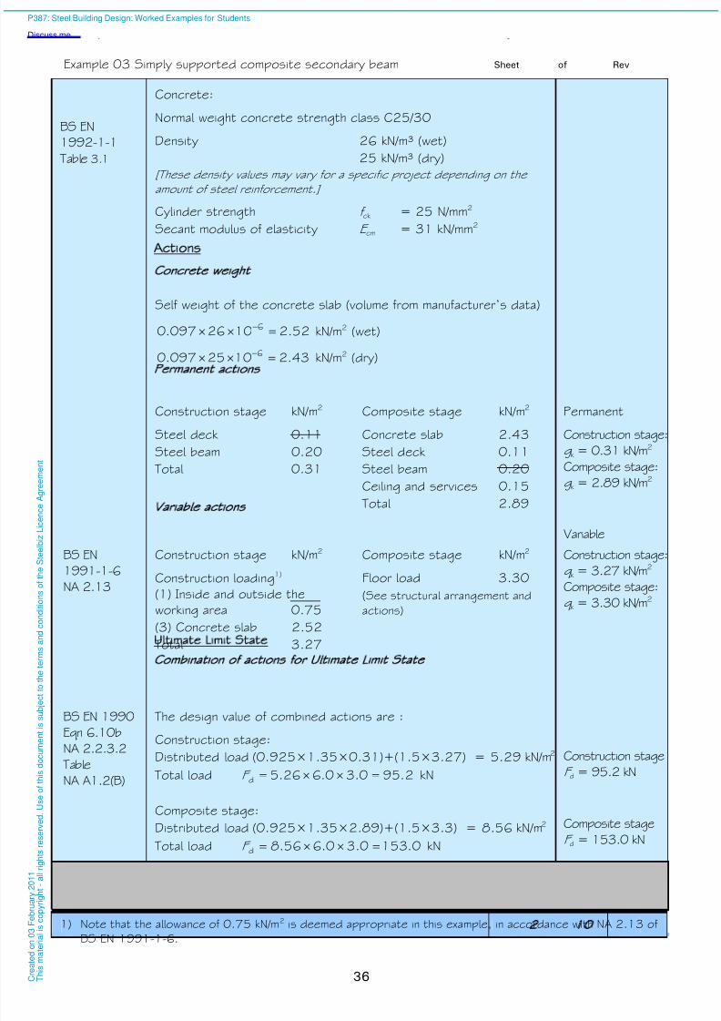
8/13/2019 p387 Calcul Imbinari in Engleza
http://slidepdf.com/reader/full/p387-calcul-imbinari-in-engleza 42/105
Example 03 Simply supported composite secondary beam Sheet 2 of 1 Rev
36
BS EN
1992-1-1
Table 3.1
Concrete:
Normal weight concrete strength class C25/30
Density 26 kN/m³ (wet)
25 kN/m³ (dry)
[These density values may vary for a specific project depending on theamount of steel reinforcement.]
Cylinder strength f ck = 25 N/mm2
Secant modulus of elasticity E cm = 31 kN/mm2
ctions
Concrete weight
Self weight of the concrete slab (volume from manufacturer’s data)
52.21026097.0 6 kN/m2 (wet)
43.21025097.0 6 kN/m2 (dry)
Permanent actions
Construction stage kN/m2
Steel deck 0.11
Steel beam 0.20
Total 0.31
Composite stage kN/m2
Concrete slab 2.43
Steel deck 0.11
Steel beam 0.20
Ceiling and services 0.15
Total 2.89
Permanent
Construction stage:
g k = 0.31 kN/m2
Composite stage:
g k = 2.89 kN/m2
Variable actions VariableBS EN
1991-1-6
NA 2.13
Construction stage kN/m2
Construction loading1)
(1) Inside and outside the
working area 0.75
(3) Concrete slab 2.52
Total 3.27
Composite stage kN/m2
Floor load 3.30
(See structural arrangement and
actions)
Construction stage:
q k = 3.27 kN/m2
Composite stage:
q k = 3.30 kN/m2
Ultimate Limit State
Combination of actions for U ltimate Limit State
BS EN 1990Eqn 6.10b
NA 2.2.3.2
Table
NA A1.2(B)
The design value of combined actions are :
Construction stage:
Distributed load (0.925×1.35×0.31)+(1.5×3.27) = 5.29 kN/m2
Total load 2.950.30.626.5d F kN
Composite stage:
Distributed load (0.925×1.35×2.89)+(1.5×3.3) = 8.56 kN/m2
Total load 0.1530.30.656.8d F kN
Construction stage
F d = 95.2 kN
Composite stage
F d = 153.0 kN
1) Note that the allowance of 0.75 kN/m2 is deemed appropriate in this example, in accordance with NA 2.13 of
BS EN 1991-1-6.
P387: Steel Building Design: Worked Examples for Students
Discuss me ...
C r e a
t e d o n
0 3 F e
b r u a r y
2 0 1 1
T h i s m a
t e r i a
l i s c o p y r i g h
t - a
l l r i g
h t s r e s e r v e
d .
U s e o
f t h i s d o c u m e n
t i s s u
b j e c
t t o t h e
t e r m s a n
d c o n
d i t i o n s o
f t h e
S t e e
l b i z
L i c e n c e
A g r e e m e n
t

8/13/2019 p387 Calcul Imbinari in Engleza
http://slidepdf.com/reader/full/p387-calcul-imbinari-in-engleza 43/105
Example 03 Simply supported composite secondary beam Sheet 3 of 1 Rev
37
Design values of moment and shear force at ULS
Construction stage
Maximum design moment (at mid span)
4.718
0.62.95
8
d
Edy,
L F M kNm
Construction stage:
M y,Ed = 71.4 kNm
Composite stage
Maximum design moment (at mid span)
8.1148
0.60.153
8d
Edy,
L F
M kNm
Maximum design shear force (at supports)
5.762
0.153
2d
Ed F
V kN
Composite stage:
M y,Ed = 114.8 kNm
V Ed = 76.5 kN
BS EN
1993-1-1
NA 2.15
BS EN
1992-1-1
NA 2
Table NA.1
NA 2.3
NA 2.4
Partial factors for resistance
Structural steel M0 = 1.0
Concrete C = 1.5
Reinforcement S = 1.15
Shear connectors V = 1.25
[Note that the National Annex states that the recommended value of Vshould be adopted in the absence of more specific information for the type
of decking being used. For simplicity, the recommended value of V is used
in this example.]
Longitudinal shear VS = 1.25
Trial section
The plastic modulus that is required to resist the construction stage
maximum design bending moment is determined as:
W pl,y = 275
0.1104.71 3
y
M0Edy,
f
M
= 259 cm
3
From the tables of section properties try
section 254 102 22 UKB, S275, which has W pl,y = 259 cm3
M y,Ed
M y,Ed
V Ed
V Ed
P387: Steel Building Design: Worked Examples for Students
Discuss me ...
C r e a
t e d o n
0 3 F e
b r u a r y
2 0 1 1
T h i s m a
t e r i a
l i s c o p y r i g h
t - a
l l r i g
h t s r e s e r v e
d .
U s e o
f t h i s d o c u m e n
t i s s u
b j e c
t t o t h e
t e r m s a n
d c o n
d i t i o n s o
f t h e
S t e e
l b i z
L i c e n c e
A g r e e m e n
t
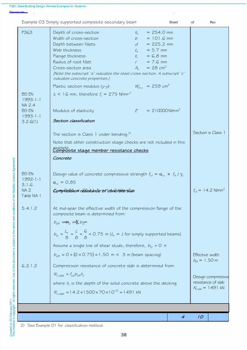
8/13/2019 p387 Calcul Imbinari in Engleza
http://slidepdf.com/reader/full/p387-calcul-imbinari-in-engleza 44/105
Example 03 Simply supported composite secondary beam Sheet 4 of 1 Rev
38
P363 Depth of cross-section h a = 254.0 mm
Width of cross-section b = 101.6 mm
Depth between fillets d = 225.2 mm
Web thickness t w = 5.7 mm
Flange thickness t f = 6.8 mm
Radius of root fillet r = 7.6 mmCross-section area Aa = 28 cm2
[Note the subscript ‘a’ indicates the steel cross section. A subscript ‘c’
indicates concrete properties.]
Plastic section modulus ( y - y ) W pl,y = 259 cm3
BS EN
1993-1-1
NA 2.4
t f < 16 mm, therefore f y = 275 N/mm2
BS EN
1993-1-1
3.2.6(1)
Modulus of elasticity E = 210000 N/mm2
Section classification
The section is Class 1 under bending.2)
Note that other construction stage checks are not included in this
example.
Section is Class 1
Composite stage member resistance checks
Concrete
BS EN
1992-1-1
3.1.6NA 2
Table NA 1
Design value of concrete compressive strength f cd = cc × f ck / c
cc = 0.85f cd = 0.85 × 25 / 1.5 = 14.2 N/mm2 f cd = 14.2 N/mm2
Compression resistance of concrete slab
5.4.1.2 At mid-span the effective width of the compression flange of the
composite beam is determined from:
ei0eff b b b
75.08
6
88e
ei L L
b m (L e = L for simply supported beams)
Assume a single line of shear studs, therefore, 00 b m
50.175.020eff b m < 3 m (beam spacing) Effective width
b eff = 1.50 m
6.2.1.2 Compression resistance of concrete slab is determined from:
ceffcdslabc, h b f N
where h c is the depth of the solid concrete above the decking
1491107015002.14 3slabc, N kN
Design compressive
resistance of slab
N c,slab = 1491 kN
2) See Example 01 for classification method.
P387: Steel Building Design: Worked Examples for Students
Discuss me ...
C r e a
t e d o n
0 3 F e
b r u a r y
2 0 1 1
T h i s m a
t e r i a
l i s c o p y r i g h
t - a
l l r i g
h t s r e s e r v e
d .
U s e o
f t h i s d o c u m e n
t i s s u
b j e c
t t o t h e
t e r m s a n
d c o n
d i t i o n s o
f t h e
S t e e
l b i z
L i c e n c e
A g r e e m e n
t
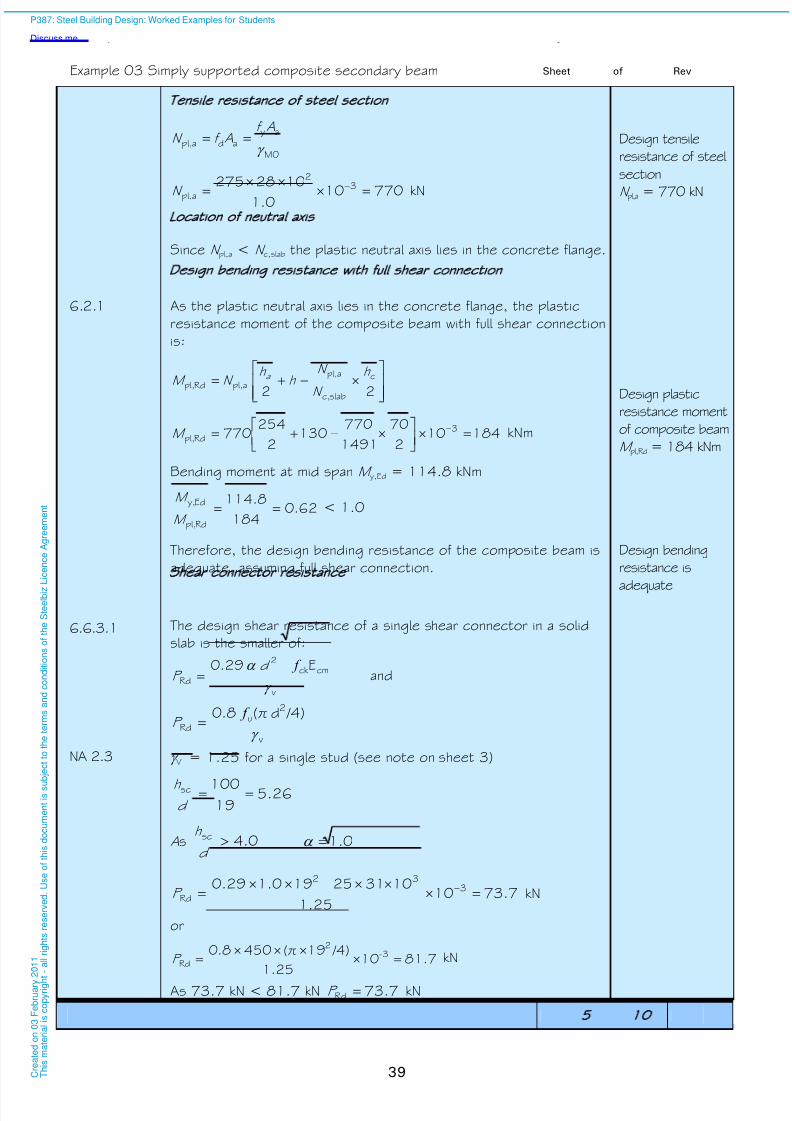
8/13/2019 p387 Calcul Imbinari in Engleza
http://slidepdf.com/reader/full/p387-calcul-imbinari-in-engleza 45/105
Example 03 Simply supported composite secondary beam Sheet 5 of 1 Rev
39
Tensile resistance of steel section
M0
ayadapl,
Af Af N
770100.1
1028275 32
apl,
N kN
Design tensile
resistance of steel
section
N pl,a = 770 kN
Location of neutral axis
Since N pl,a < N c,slab the plastic neutral axis lies in the concrete flange.
Design bending resistance w ith full shear connection
6.2.1 As the plastic neutral axis lies in the concrete flange, the plastic
resistance moment of the composite beam with full shear connection
is:
22
c
slabc,
apl,
apl,Rdpl,
h
N
N h
h N M a
184102
70
1491
770130
2
254770 3
Rdpl,
M kNm
Design plasticresistance moment
of composite beam
M pl,Rd = 184 kNm
Bending moment at mid span M y,Ed = 114.8 kNm
62.0184
8.114
Rdpl,
Edy, M
M < 1.0
Therefore, the design bending resistance of the composite beam is
adequate, assuming full shear connection.
Design bending
resistance is
adequate
6.6.3.1
Shear connector resistance
The design shear resistance of a single shear connector in a solid
slab is the smaller of:
E29.0
v
cmck 2
Rd
f d P and
/4)d π(8.0
v
2u
Rd
f P
NA 2.3 V = 1.25 for a single stud (see note on sheet 3)
5.2619100sc
d h
As 0.4sc d
h 0.1
73.71025.1
103125191.029.0 332
Rd
P kN
or
81.71025.1
/4)19 π(4508.0 3-2
Rd
P kN
As 73.7 kN < 81.7 kN 73.7Rd P kN
P387: Steel Building Design: Worked Examples for Students
Discuss me ...
C r e a
t e d o n
0 3 F e
b r u a r y
2 0 1 1
T h i s m a
t e r i a
l i s c o p y r i g h
t - a
l l r i g
h t s r e s e r v e
d .
U s e o
f t h i s d o c u m e n
t i s s u
b j e c
t t o t h e
t e r m s a n
d c o n
d i t i o n s o
f t h e
S t e e
l b i z
L i c e n c e
A g r e e m e n
t
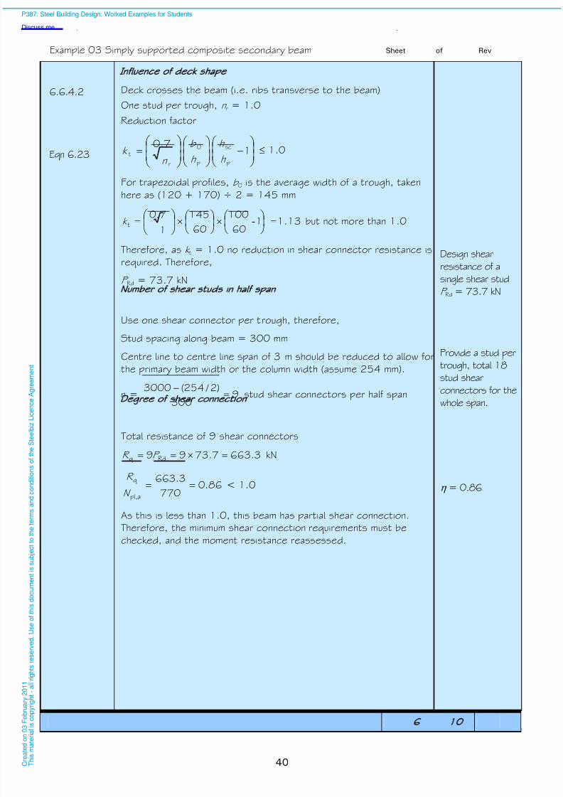
8/13/2019 p387 Calcul Imbinari in Engleza
http://slidepdf.com/reader/full/p387-calcul-imbinari-in-engleza 46/105
Example 03 Simply supported composite secondary beam Sheet 6 of 1 Rev
40
6.6.4.2
Eqn 6.23
Influence of deck shape
Deck crosses the beam (i.e. ribs transverse to the beam)
One stud per trough, n r = 1.0
Reduction factor
17.0
p
sc
p
0
r
th
h
h
b
n k 1.0
For trapezoidal profiles, b 0 is the average width of a trough, taken
here as (120 + 170) ÷ 2 = 145 mm
1.13 160
100
60
145
1
7.0t
-k but not more than 1.0
Therefore, as k t = 1.0 no reduction in shear connector resistance is
required. Therefore,
P Rd = 73.7 kN
Design shear
resistance of a
single shear studP Rd = 73.7 kN
Number of shear studs in half span
Use one shear connector per trough, therefore,
Stud spacing along beam = 300 mm
Centre line to centre line span of 3 m should be reduced to allow for
the primary beam width or the column width (assume 254 mm).
n = 9300
)2 /254(3000
stud shear connectors per half span
Provide a stud per
trough, total 18
stud shear
connectors for the
whole span.
Degree of shear connection
Total resistance of 9 shear connectors
3.6637.7399 Rdq P R kN
86.0770
3.663
apl,
q N
R < 1.0
As this is less than 1.0, this beam has partial shear connection.
Therefore, the minimum shear connection requirements must be
checked, and the moment resistance reassessed.
= 0.86
P387: Steel Building Design: Worked Examples for Students
Discuss me ...
C r e a
t e d o n
0 3 F e
b r u a r y
2 0 1 1
T h i s m a
t e r i a
l i s c o p y r i g h
t - a
l l r i g
h t s r e s e r v e
d .
U s e o
f t h i s d o c u m e n
t i s s u b
j e c
t t o t h e
t e r m s a n
d c o n
d i t i o n s o
f t h e
S t e e
l b i z L i c e n c e
A g r e e m e n
t
8/13/2019 p387 Calcul Imbinari in Engleza
http://slidepdf.com/reader/full/p387-calcul-imbinari-in-engleza 47/105
Example 03 Simply supported composite secondary beam Sheet 7 of 1 Rev
41
6.6.1.2
Minimum shear connection requirements
The minimum shear connection requirement is calculated from:
(for L e < 25m):
4.0,03.075.0
355
1 ey
L f
For a simply supported beam, L e is equal to the span.
4.0,26.0603.075.0275
3551
Therefore the degree of shear connection must be at least 0.4. As
shown above, there are a sufficient number of shear connectors to
achieve this.
6.2.1.3 Design bending moment resistance with partial shear connection
The design bending moment can conservatively be calculated using:
Rda,pl,Rdpl,Rda,pl,Rd M M M M
M pl,a,Rd is the plastic moment resistance of the steel section:
2.7110259275 3ypl,ydRda,pl, W f M kNm
So the design bending moment resistance is:
2.16886.02.711842.71Rd M kNm
Bending moment at mid span M y,Ed = 114.8 kNm
68.02.168
8.114
Rd
Edy, M
M < 1.0
Therefore, the design bending resistance of the composite beam
with partial shear connection is adequate.Design bending
resistance is
adequate
BS EN
1993-1-1
6.2.6(6)
Shear buckling resistance of the uncased web
BS EN1993-1-5
5.1(2)
For unstiffened webs if 72w t
h the shear buckling resistance of
the web should be checked.
Where:
92.0275
235235
y
f
BS EN
1993-1-1
6.2.6(6)
= 1.0 (conservative)
4.2408.622542 faw t h h mm h w = 240.4 mm
2.6692.00.1
7272
P387: Steel Building Design: Worked Examples for Students
Discuss me ...
C r e a
t e d o n
0 3 F e
b r u a r y
2 0 1 1
T h i s m a
t e r i a
l i s c o p y r i g h
t - a
l l r i g
h t s r e s e r v e
d .
U s e o
f t h i s d o c u m e n
t i s s u
b j e c
t t o t h e
t e r m s a n
d c o n
d i t i o n s o
f t h e
S t e e
l b i z
L i c e n c e
A g r e e m e n
t

8/13/2019 p387 Calcul Imbinari in Engleza
http://slidepdf.com/reader/full/p387-calcul-imbinari-in-engleza 48/105
Example 03 Simply supported composite secondary beam Sheet 8 of 1 Rev
42
2.427.5
4.240
w
ww t
h
t
h
As 42.2 < 66.2 the shear buckling resistance of the web does not
need to be checked.
Shear buckling
resistance check is
not required.Resistance to vertical shear
6.2.2.2
Vertical shear resistance of the composite beam is:
3
M0
yv Rda,pl,Rdpl,
f AV V
BS EN
1993-1-1
6.2.6(3)
For rolled I and H sections loaded parallel to the web:
r t t bt AA 22 wffv but not less than wwt h
)6.72(7.58.6)8.66.1012(2800v A
1560v A mm2
0.1 (Conservatively from note to 6.2.6(3))
13707.54.2400.1ww t h mm2
1560 mm2 > 1370 mm2
Therefore, 1560v A mm2
247100.13
2751560 3-
Rdpl,
V kNDesign vertical
shear resistance
V pl,Rd = 247 kN
31.0247
5.76
Rdpl,
Ed V
V < 1.0
Therefore the design resistance to vertical shear is adequate.
Design resistance
for vertical shear is
adequate
6.2.2.4 As there is no shear force at the point of maximum bending moment
(mid span) no reduction (due to shear) in bending resistance is
required.
Design of the transverse reinforcement
For simplicity, neglect the contribution of the decking and check the
resistance of the reinforced concrete flange to splitting.
BS EN
1992-1-1
6.2.4 (4)
The area of reinforcement (Asf) can be determined using the following
equation:
f
ydsf
s
f A >
f
h v
cotfEd therefore,
f
sf
s
A >
f f
h v
cotyd
fEd
P387: Steel Building Design: Worked Examples for Students
Discuss me ...
C r e a
t e d o n
0 3 F e
b r u a r y
2 0 1 1
T h i s m a
t e r i a
l i s c o p y r i g h
t - a
l l r i g
h t s r e s e r v e
d .
U s e o
f t h i s d o c u m e n
t i s s u
b j e c
t t o t h e
t e r m s a n
d c o n
d i t i o n s o
f t h e
S t e e
l b i z
L i c e n c e
A g r e e m e n
t

8/13/2019 p387 Calcul Imbinari in Engleza
http://slidepdf.com/reader/full/p387-calcul-imbinari-in-engleza 49/105
Example 03 Simply supported composite secondary beam Sheet 9 of 1 Rev
43
6.6.6.4 (1)
where:
h f is the depth of concrete above the metal decking, therefore,
h f = h c = 70 mm
S f is the spacing of the transverse reinforcement
4351.15
500
s
yyd
f f N/mm2
For compression flanges 26.5° f 45°
6.6.6.1
Figure 6.16
The longitudinal shear stress is the stress transferred from the steel
beam to the concrete. This is determined from the minimum
resistance of the steel, concrete and shear connectors. In this
example, with partial shear connection, that maximum force that can
be transferred is limited by the resistance of the shear connectors
over half of the span, and is given by R q = 663.3 kN
This force must be transferred over each half-span. As there are twoshear planes (one on either side of the beam, running parallel to it),
the longitudinal shear stress is:
58.13000702
1000663
2 fEd
x h
R v
q
N/mm²
For minimum area of transverse reinforcement assume = 26.5°
BS EN
1992-1-1
6.2.4 (4)f
sf
s
A 7.12610
6.52cot435
7058.1
cot
3
yd
fEd
f f
h v
mm2 /m
Therefore, provide A193 mesh reinforcement (193mm2
/m)
in theslab.3)
Use A193 mesh
reinforcement
BS EN
1992-1-1
6.2.4 (4)
BS EN1992-1-1
NA 2
Table NA.1
Crushing of the concrete compression strut
The model for resisting the longitudinal shear assumes compression
struts form in the concrete slab
Verify that:
ffcdEd cossin f v
where:
=
250
16.0 ck f -
= 54.0250
2516.0
-
06.35.26cos5.26sin2.1454.0cossincd f f f N/mm²
58.1Ed v N/mm² < 3.06 N/mm²
Therefore the crushing resistance of the compression strut isadequate.
3) If the contribution of decking is included, the transverse reinforcement provided can be reduced.
P387: Steel Building Design: Worked Examples for Students
Discuss me ...
C r e a
t e d o n
0 3 F e
b r u a r y
2 0 1 1
T h i s m a
t e r i a
l i s c o p y r i g h
t - a
l l r i g
h t s r e s e r v e
d .
U s e o
f t h i s d o c u m e n
t i s s u
b j e c
t t o t h e
t e r m s a n
d c o n
d i t i o n s o
f t h e
S t e e
l b i z
L i c e n c e
A g r e e m e n
t

8/13/2019 p387 Calcul Imbinari in Engleza
http://slidepdf.com/reader/full/p387-calcul-imbinari-in-engleza 50/105
Example 03 Simply supported composite secondary beam Sheet 1 of 1 Rev
44
Serviceability limit state
Performance at the serviceability limit state should be verified.
However, no verification is included here. The National Annex for the
country where the building is to be constructed should be consulted
for guidance.
Considerations would be:
• Short-term, long-term and dynamic modular ratios
• Serviceability combinations of actions
• Composite bending stiffness of the beam
• Total deflection and deflection due to imposed loads
• Stresses in steel and concrete (to validate deflection
assumptions)
• Natural frequency.
P387: Steel Building Design: Worked Examples for Students
Discuss me ...
C r e a
t e d o n
0 3 F e
b r u a r y
2 0 1 1
T h i s m a
t e r i a
l i s c o p y r i g h
t - a
l l r i g
h t s r e s e r v e
d .
U s e o
f t h i s d o c u m e n
t i s s u
b j e c
t t o t h e
t e r m s a n
d c o n
d i t i o n s o
f t h e
S t e e
l b i z
L i c e n c e
A g r e e m e n
t

8/13/2019 p387 Calcul Imbinari in Engleza
http://slidepdf.com/reader/full/p387-calcul-imbinari-in-engleza 51/105
Job No. Sheet 1 of 6 Rev C
Job Title Example no. 04 Revised by DGB, April 09
Subject Edge beam
Made by MXT Date Dec 2007
Silwood Park, Ascot, Berks SL5 7QN
Telephone: (01344) 636525
Fax: (01344) 636570
CALCULATION SHEET
Client
Checked by AB Date April 2007
45
Unless stated
otherwise all
references
are to BS EN
1993-1-1
Edge beam with torsion
Each 6 m span edge beams is unrestrained along its length. It
carries permanent loads only. The brickwork load is applied with an
eccentricity of 172 mm to the centroidal axis and induces torsion
to the beam. The chosen member is a RHS, which is excellent at
resisting torsion.
Block Brick
RHS
172
End detail
Actions
Permanent actions
Uniformly Distributed Load (brickwork) g 1 = 4.8 kN/m
Uniformly Distributed Load (blockwork) g 2 = 3.0 kN/m
Uniformly Distributed Load
(assumed self weight) g 3 = 0.47 kN/m
Ultimate Limit State ULS)
Partial factors for actions
BS EN 1990
A1.3.1(4)
For the design of structural members not involving geotechnical
actions, the partial factors for actions to be used for ultimate limitstate design should be obtained from Table A1.2(B) and the
National Annex
NA 2.2.3.2
Table
NA.A1.2(B)
Partial factor for permanent actions G = 1.35
Reduction factor = 0.925
Combination of actions for ULS
This example uses BS EN 1990 Equation 6.10b. Expression 6.10a
should also be checked, which may be more onerous.
UDL (total permanent)
)( 321Gd g g g F kN/m
BS EN 1990 Table A1.2(B)
& Eq. (6.10b)
33.10=)47.0+0.3+8.4(×35.1×925.0=dF kN/m
P387: Steel Building Design: Worked Examples for Students
Discuss me ...
C r e a
t e d o n
0 3 F e
b r u a r y
2 0 1 1
T h i s m a
t e r i a
l i s c o p y r i g h
t - a
l l r i g
h t s r e s e r v e
d .
U s e o
f t h i s d o c u m e n
t i s s u
b j e c
t t o t h e
t e r m s a n
d c o n
d i t i o n s o
f t h e
S t e e
l b i z
L i c e n c e
A g r e e m e n
t

8/13/2019 p387 Calcul Imbinari in Engleza
http://slidepdf.com/reader/full/p387-calcul-imbinari-in-engleza 52/105
Example 04 Edge beam Sheet 2 of 6 Rev
46
UDL (permanent, inducing torsion)
99.5=8.4×35.1×925.0=×= 1G Td, G F kN/m
Design moments and shear force
Span of beam L = 6000 mm
Eccentricity of brickwork e = 172 mm
Maximum design bending moment occurs at the mid-span
5.46=8
6×33.10=
8=
22d
Ed
L F M kNm
Design bending
moment
M Ed = 46.5kNm
Maximum design shear force occurs at the supports
0.31=
2
6×33.10=
2
= dEd
L F V kN
Design shear
forceV Ed = 31.0 kN
Maximum design torsional moment occurs at the supports
1.3=2
6×172.0×99.5=
2
××=
TEd,Ed
L e F T kNm
Design torsional
moment
T Ed = 3.1 kNm
The design bending moment, torsional moment and shear force
diagrams are shown below.
Bending moment
Shear force
Torsional moment
46.5 kNm
31.0 kN
31.0 kN
3.1 kNm
3.1 kNm
P387: Steel Building Design: Worked Examples for Students
Discuss me ...
C r e a
t e d o n
0 3 F e
b r u a r y
2 0 1 1
T h i s m a
t e r i a
l i s c o p y r i g h
t - a
l l r i g
h t s r e s e r v e
d .
U s e o
f t h i s d o c u m e n
t i s s u
b j e c
t t o t h e
t e r m s a n
d c o n
d i t i o n s o
f t h e
S t e e
l b i z
L i c e n c e
A g r e e m e n
t

8/13/2019 p387 Calcul Imbinari in Engleza
http://slidepdf.com/reader/full/p387-calcul-imbinari-in-engleza 53/105
Example 04 Edge beam Sheet 3 of 6 Rev
47
Trial section
P363 Try 250 150 8.0 RHS in S355 steel. The RHS is class 1
under the given loading.
Depth of section h = 250 mmWidth of section b = 150 mm
Wall thickness t = 8 mm
Plastic modulus about the y-axis W pl,y = 501 cm3
Cross-sectional area A = 6080 cm2
St Venant torsional constant I T = 5020 cm4
Torsional section modulus W t = 506 cm3
Second moment of area about z-z axis I z = 2300 cm4
NA 2.4
BS EN10210-1
Table A3
For steel grade S355 and t < 16 mm
Yield strength f y = 355 N/mm
2
Partial factors for resistance
NA 2.15 M0 = 1.0 Resistance of the cross section
Note that the following verification assumes that the maximum shear,
bending and torsion are coincident, which is conservative.
6.2.6 Plastic shear resistance
V pl,Rd =
M0
yv 3
f A
Where Av = h b
Ah
=
150250
2506080
= 3800 mm2
V pl,Rd =3100.1
33553800
= 779 kN, > 28.5 kN, OK
6.2.6(6) Shear buckling resistance
The shear buckling resistance for webs should be checked according
to section 5 of BS EN 1993-1-5 if:
Eq. 6.22
ε72
w
w t
h
Table 5.2 81.0355
235235
y
f
P387: Steel Building Design: Worked Examples for Students
Discuss me ...
C r e a
t e d o n
0 3 F e
b r u a r y
2 0 1 1
T h i s m a
t e r i a
l i s c o p y r i g h
t - a
l l r i g
h t s r e s e r v e
d .
U s e o
f t h i s d o c u m e n
t i s s u
b j e c
t t o t h e
t e r m s a n
d c o n
d i t i o n s o
f t h e
S t e e
l b i z
L i c e n c e
A g r e e m e n
t

8/13/2019 p387 Calcul Imbinari in Engleza
http://slidepdf.com/reader/full/p387-calcul-imbinari-in-engleza 54/105
Example 04 Edge beam Sheet 4 of 6 Rev
48
6.2.6(6) = 1.0 (conservative)
2260.832503w t h h mm
3.280.8
226
w
w t
h
580.1
81.07272
28.3 < 58 Therefore the shear buckling resistance of the web
does not need to be checked.
6.2.7 Torsional resistance
6.2.7(7)
The torsional moment may be considered as the sum of two internal
effects:
T Ed = T t,Ed + T w,Ed
But T w,Ed may be neglected for hollow sections
For a closed section, T Rd =M0
ty
3
W f
= 63
100.13
10506355
= 103.7 kNm
103.7 > 3.1, OK
6.2.7(9)Eqn 6.25
Shear and torsion
0.1Rd T,pl,
Ed V
V
For a structural hollow section
Rdpl,
M0y
Edt,
Rd T,pl,
31 V
f V
Shear stress due to torsion,
t
Edt,Edt,
W
T
3
6
Edt,10×506
10×1.3= = 6.1 N/mm2
Then Rdpl,
M0y
Edt,
Rd T,pl,
31 V
f V
779
0.13355
5.51Rd T,pl,
V = 758 kN
31.0 < 758, OK
P387: Steel Building Design: Worked Examples for Students
Discuss me ...
C r e a
t e d o n
0 3 F e
b r u a r y
2 0 1 1
T h i s m a
t e r i a
l i s c o p y r i g h
t - a
l l r i g
h t s r e s e r v e
d .
U s e o
f t h i s d o c u m e n
t i s s u
b j e c
t t o t h e
t e r m s a n
d c o n
d i t i o n s o
f t h e
S t e e
l b i z
L i c e n c e
A g r e e m e n
t
8/13/2019 p387 Calcul Imbinari in Engleza
http://slidepdf.com/reader/full/p387-calcul-imbinari-in-engleza 55/105
Example 04 Edge beam Sheet 5 of 6 Rev
49
6.2.8(2) Bending and shear
The shear force (V Ed = 31.0 kN) is less than half the plastic shear
resistance (V pl,Rd = 779 kN), so no reduction in the bending
resistance due to the presence of shear is required.
6.2.8(4) Bending shear and torsion
The shear force (VEd = 31.0 kN) is less than half the plastic shear
resistance accounting for torsional effects (V pl,T,Rd = 758 kN), so
= 0 and therefore the yield strength used in calculating the
bending resistance need not be reduced.
Bending resistance
6.2.5 Cross section resistance
6.2.5(2) The design resistance for bending for Class 1 and 2 cross-sections
is:
9.177100.1
355105016
3
M0
yypl,
Rdpl,Rdc,
f W M M kNm
Design bending
resistance, M c,Rd
= 177.9 kNm
177.9 > 46.5, OK
6.3.2 Buckling resistance
6.3.2.2(4) For slendernesses LT,0LT lateral torsional buckling effects may
be ignored.
NA 2.17 LT,0 = 0.4
6.3.2.2(1) The slenderness LT is given bycr
yyLT
M
f W
Access-steel
document
SN003a-EN-
EU
For non-destabilising loads, and where warping is neglected, the
elastic critical moment for lateral-torsional buckling, M cr is given by:
z
2
T2
2
2
1cr π
π
EI
GI L
L
EI C M
Where:
E is the modulus of elasticity (E = 210000 N/mm2)
G is the shear modulus (G = 81000 N/mm2)
I z is the second moment of area about the minor axis
I T is the St Venant torsional constant
L is the beam length between points of lateral restraint
Access-steel
document
SN003a
Table 3.2
C 1 accounts for actual moment distribution
C 1 = 1.127 (for simply supported beam with a UDL).
P387: Steel Building Design: Worked Examples for Students
Discuss me ...
C r e a
t e d o n
0 3 F e
b r u a r y
2 0 1 1
T h i s m a
t e r i a
l i s c o p y r i g h
t - a
l l r i g
h t s r e s e r v e
d .
U s e o
f t h i s d o c u m e n
t i s s u
b j e c
t t o t h e
t e r m s a n
d c o n
d i t i o n s o
f t h e
S t e e
l b i z
L i c e n c e
A g r e e m e n
t

8/13/2019 p387 Calcul Imbinari in Engleza
http://slidepdf.com/reader/full/p387-calcul-imbinari-in-engleza 56/105
Example 04 Edge beam Sheet 6 of 6 Rev
50
42
42
2
42
cr
102300210000 π
105020810006000
6000
102300210000 π
127.1M
Hence, M cr=2615 kNm M cr = 2615 kNm
6.3.2.2(1)
6
3
cr
yypl,
cr
yyLT
102615
35510501
M
f W
M
f W 0.26 26.0=LT
0.26 < 0.4, so lateral-torsional buckling effects can be neglected.
Serviceability limit state SLS)
Twist at SLS
In this case, twist will be assessed under the unfactored permanent
loads.
Partial factors for actions
Partial factor for permanent actions G = 1.0
Maximum torsional moment =925.0×35.1
0.1×1.3= 2.48 kNm
Maximum twist per unit length is given by:
Twist =
t
Ed
GI
T =
4
6
10×5020×81000
10×48.2
= 6.1 × 10⁻⁷ radians/mm
Twist at midspan = 0.5 × 6.1 × 10 –7 × 3000 = 0.9 × 10 –3
radians
= 0.05 degrees
Note that this calculation assumes that the support conditions
prevent any form of twisting – so friction grip connections or similar
may be required.
P387: Steel Building Design: Worked Examples for Students
Discuss me ...
C r e a
t e d o n
0 3 F e
b r u a r y
2 0 1 1
T h i s m a
t e r i a
l i s c o p y r i g h
t - a
l l r i g
h t s r e s e r v e
d .
U s e o
f t h i s d o c u m e n
t i s s u
b j e c
t t o t h e
t e r m s a n
d c o n
d i t i o n s o
f t h e
S t e e
l b i z
L i c e n c e
A g r e e m e n
t

8/13/2019 p387 Calcul Imbinari in Engleza
http://slidepdf.com/reader/full/p387-calcul-imbinari-in-engleza 57/105
Job No. Sheet 1 of 4 Rev C
Job Title Example no. 05 Revised by DGB, April 09
Subject Column in Simple Construction
Made by LG Date Dec 2007
Silwood Park, Ascot, Berks SL5 7QN
Telephone: (01344) 636525
Fax: (01344) 636570
CALCULATION SHEET
Client
Checked by PS Date Dec 2007
51
Column in Simple ConstructionUnless stated
otherwise all
references
are to BS EN
1993-1-
1:2005
Description
This example demonstrates the design of an internal column in simple
construction. Note that the internal columns do not carry roof
loads.
Internal column at ground level – Gridline G2
Column height = 5.0 m
See structural
arrangement
and actions
Actions
Reactions at each of the three floor levels from 8 m span beams:
Permanent = 0.5 × 8 × 6 × 3.7 = 88.8 kN
Variable = 0.5 × 8 × 6 × 3.3 = 79.2 kN
Reactions at each of the three floor levels from 6 m span beams:
Permanent = 0.5 × 6 × 6 × 3.7 = 66.6 kN
Variable = 0.5 × 6 × 6 × 3.3 = 59.4 kN
The total load acting on the column due to three floors is given by:
Permanent G k = 3 (88.8 + 66.6) = 466.2 kN
Variable Q k = 3 (79.2 + 59.4) = 415.8 kN
G k = 466.2 kN
Q k = 415.8 kN
Ultimate Limit State ULS)
BS EN 1990
Table A1(2)B
NA 2.2.3.2
Table
NA.A1.2(B)
Partial factors for actions
For permanent actions G = 1.35
For variable actions Q = 1.5
Reduction factor
= 0.925
BS EN 1990
6.4.3.2
Design value of combined actions from equation 6.10b
= G G k + Q Q k
= 0.925 1.35 466.2 + 1.5 415.8 = 1206 kN
The ULS axial
load,
N Ed = 1206 kN
At level 1,
The reaction from an 8 m beam is
0.925 × 1.35 × 88.8 + 1.5 × 79.2 = 230 kN
The reaction from an 6 m beam is
0.925 × 1.35 × 66.6 + 1.5 × 59.4 = 172 kN
P387: Steel Building Design: Worked Examples for Students
Discuss me ...
C r e a
t e d o n
0 3 F e
b r u a r y
2 0 1 1
T h i s m a
t e r i a
l i s c o p y r i g h
t - a
l l r i g
h t s r e s e r v e
d .
U s e o
f t h i s d o c u m e n
t i s s u
b j e c
t t o t h e
t e r m s a n
d c o n
d i t i o n s o
f t h e
S t e e
l b i z
L i c e n c e
A g r e e m e n
t
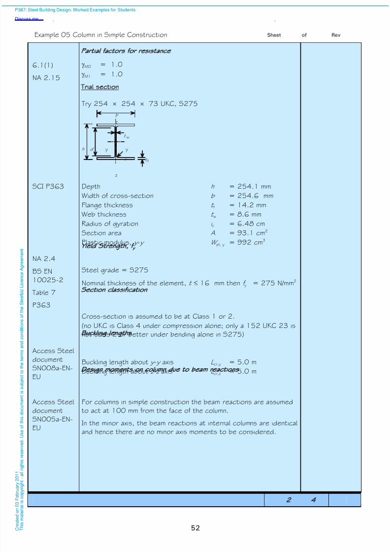
8/13/2019 p387 Calcul Imbinari in Engleza
http://slidepdf.com/reader/full/p387-calcul-imbinari-in-engleza 58/105
Example 05 Column in Simple Construction Sheet 2 of 4 Rev
52
6.1(1)
NA 2.15
Partial factors for resistance
M0 = 1.0
M1 = 1.0
Trial section
Try 254 254 73 UKC, S275
z
z
y y
f
w
b
dh
tr
t
SCI P363 Depth h = 254.1 mm
Width of cross-section b = 254.6 mm
Flange thickness t f = 14.2 mm
Web thickness t w = 8.6 mm
Radius of gyration i z = 6.48 cm
Section area A = 93.1 cm2
Plastic modulus, y - y W pl, y = 992 cm3
NA 2.4
BS EN
10025-2
Table 7
Yield Strength fy
Steel grade = S275
Nominal thickness of the element, t 16 mm then f y = 275 N/mm2
P363 Section classification
Cross-section is assumed to be at Class 1 or 2.
(no UKC is Class 4 under compression alone; only a 152 UKC 23 is
not class 2 or better under bending alone in S275)
Access Steel
document
SN008a-EN-
EU
Buckling lengths
Buckling length about y - y axis L cr,y = 5.0 m
Buckling length about z -z axis L cr,z = 5.0 m
Design moments on column due to beam reactions
For columns in simple construction the beam reactions are assumed
to act at 100 mm from the face of the column.
Access Steel
document
SN005a-EN-
EU In the minor axis, the beam reactions at internal columns are identical
and hence there are no minor axis moments to be considered.
P387: Steel Building Design: Worked Examples for Students
Discuss me ...
C r e a
t e d o n
0 3 F e
b r u a r y
2 0 1 1
T h i s m a
t e r i a
l i s c o p y r i g h
t - a
l l r i g
h t s r e s e r v e
d .
U s e o
f t h i s d o c u m e n
t i s s u
b j e c
t t o t h e
t e r m s a n
d c o n
d i t i o n s o
f t h e
S t e e
l b i z
L i c e n c e
A g r e e m e n
t
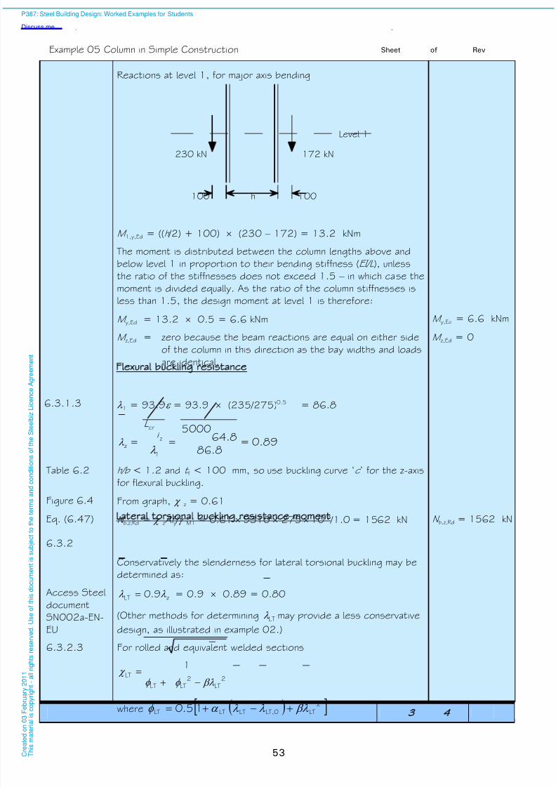
8/13/2019 p387 Calcul Imbinari in Engleza
http://slidepdf.com/reader/full/p387-calcul-imbinari-in-engleza 59/105
Example 05 Column in Simple Construction Sheet 3 of 4 Rev
53
Reactions at level 1, for major axis bending
Level 1
100 100h
230 kN 172 kN
M 1,y,Ed = ((h /2) + 100) (230 – 172) = 13.2 kNm
The moment is distributed between the column lengths above and
below level 1 in proportion to their bending stiffness (EI/L ), unless
the ratio of the stiffnesses does not exceed 1.5 – in which case themoment is divided equally. As the ratio of the column stiffnesses is
less than 1.5, the design moment at level 1 is therefore:
M y,Ed = 13.2 0.5 = 6.6 kNm M y,Ed = 6.6 kNm
M z,Ed = zero because the beam reactions are equal on either side
of the column in this direction as the bay widths and loads
are identical.
M z,Ed = 0
6.3.1.3
Flexural buckling resistance
1 = 93.9 = 93.9 (235/275)0.5 = 86.8
z =1
z
cr
i L
= 89.0=8.86
8.645000
Table 6.2
Figure 6.4
h/b < 1.2 and t f < 100 mm, so use buckling curve ‘c ’ for the z-axis
for flexural buckling.
From graph, z = 0.61
Eq. (6.47) N b,z,Rd = zAf y / M1 = 0.61 9310 275 10 –3 /1.0 = 1562 kN N b,z,Rd = 1562 kN
6.3.2 Lateral torsional buckling resistance moment
Conservatively the slenderness for lateral torsional buckling may be
determined as:
Access Steel
document
SN002a-EN-
EU
zLT 9.0 = 0.9 0.89 = 0.80
(Other methods for determining LT may provide a less conservative
design, as illustrated in example 02.)
6.3.2.3 For rolled and equivalent welded sections
2
LT
2
LTLT
LT
1
where 2LTLT,0LTLTLT 15.0
P387: Steel Building Design: Worked Examples for Students
Discuss me ...
C r e a
t e d o n
0 3 F e
b r u a r y
2 0 1 1
T h i s m a
t e r i a
l i s c o p y r i g h
t - a
l l r i g
h t s r e s e r v e
d .
U s e o
f t h i s d o c u m e n
t i s s u
b j e c
t t o t h e
t e r m s a n
d c o n
d i t i o n s o
f t h e
S t e e
l b i z
L i c e n c e
A g r e e m e n
t

8/13/2019 p387 Calcul Imbinari in Engleza
http://slidepdf.com/reader/full/p387-calcul-imbinari-in-engleza 60/105
Example 05 Column in Simple Construction Sheet 4 of 4 Rev
54
6.3.2.3
NA 2.17
0,LT = 0.4
= 0.75
Table 6.5
Table 6.3
For rolled bi-symmetric I-sections with h/b ≤ 2:
use buckling curve ‘b ’.
For buckling curve ‘b ’, LT = 0.34
81.080.075.0)40.080.0(34.015.0 2LT
81.080.075.081.081.0
1
22LT
6.3.2.3 But the following restrictions apply:
0.1LT
56.180.011
22LT
LT
81.0LT
6.3.2.1(3)M b,Rd =
M1
yypl,LT
M1
yyLT
f W f W for Class 1 or 2 cross-sections
2210.1
1027599281.0 3
kNmM b,Rd = 221 kNm
Combined bending and axial compression buckling simplified)SN048a-EN-GB Access
Steel
document
Instead of equation 6.61 and 6.62, the simplified expression given
below is used:
0.1≤5.1Rdz,
Edz,
Rdb,
Edy,
Rdz,b,
Ed
M
M
M
M
N
N
0.180.0=0+221
6.6+
1562
1206≤
Therefore a 254 254 73 UKC is adequate. Section used is
254254
73UKC, S275
P387: Steel Building Design: Worked Examples for Students
Discuss me ...
C r e a
t e d o n
0 3 F e
b r u a r y
2 0 1 1
T h i s m a
t e r i a
l i s c o p y r i g h
t - a
l l r i g
h t s r e s e r v e
d .
U s e o
f t h i s d o c u m e n
t i s s u
b j e c
t t o t h e
t e r m s a n
d c o n
d i t i o n s o
f t h e
S t e e
l b i z
L i c e n c e
A g r e e m e n
t

8/13/2019 p387 Calcul Imbinari in Engleza
http://slidepdf.com/reader/full/p387-calcul-imbinari-in-engleza 61/105
Job No. Sheet 1 of 5 Rev C
Job Title Example no. 06 Revised by DGB, April 09
Subject Roof Truss
Made by LYL Date Nov 07
Silwood Park, Ascot, Berks SL5 7QN
Telephone: (01344) 636525
Fax: (01344) 636570
CALCULATION SHEET
Client
Checked by IB Date Jan 2008
55
BS EN 1991-
1-1
Tables 6.9 &
6.10
NA 2.10
Table NA 7
Roof Truss
The truss to be designed is to support a roof which is only
accessible for normal maintenance and repair. The truss is 14 m
span with 15° pitch. The dimensions of the truss are shown in the
figure below. The imposed roof load due to snow obtained from
BS EN 1991-1-3 is less than 0.6 kN/m2, therefore the
characteristic imposed roof load is taken from BS EN 1991-1-1 and
the National Annex. The truss uses hollow sections for its tension
chord, rafters, and internal members. The truss is fully welded. Truss analysis is carried out by placing concentrated loads at the
joints of the truss. All of the joints are assumed to be pinned in the
analysis and therefore only axial forces are carried by members.
Unless stated
otherwise all
references
are to BS EN
1993-1-1
A C
G
E H
D
B
15°30°
64983751 3751
3500 3500 3500 3500
d d
d
d
d
/2 /2
F
F
F
F F
Characteristic actions
Permanent actions
Self weight of roof construction 0.75 kN/m2
Self weight of services 0.15 kN/m2
Total permanent actions 0.90 kN/m2
Variable actions
Imposed roof load 0.60 kN/m2
Total imposed action 0.60 kN/m2
Ultimate Limit State ULS)
NA 2.2.3.2
Table
NA.A1.2(B)
Partial factors for actions
Partial factor for permanent actions G = 1.35
Partial factor for variable actions G = 1.5
Reduction factor = 0.925
Design value of combined actions, using equation 6.10b
= 0.925 × 1.35 × 0.9 + 1.5 × 0.6 = 2.02 kN/m2
P387: Steel Building Design: Worked Examples for Students
Discuss me ...
C r e a
t e d o n
0 3 F e
b r u a r y
2 0 1 1
T h i s m a
t e r i a
l i s c o p y r i g h
t - a
l l r i g
h t s r e s e r v e
d .
U s e o
f t h i s d o c u m e n
t i s s u
b j e c
t t o t h e
t e r m s a n
d c o n
d i t i o n s o
f t h e
S t e e
l b i z
L i c e n c e
A g r e e m e n
t

8/13/2019 p387 Calcul Imbinari in Engleza
http://slidepdf.com/reader/full/p387-calcul-imbinari-in-engleza 62/105
Example 06 Roof truss Sheet 2 of 5 Rev
56
Design values of combined actions on purlins supported by truss
For the distance of 3.5 m between purlins centre to centre
Design value = 2.02 3.5/ cos15o = 7.32 kN/m
Design value of combined actions on truss
For a purlin span of 6 m
Fd = 7.32 6 = 43.92 kNF d = 43.92 kN
Truss analysis due to forces Fd )
Reaction force at support A R A =2 F d = 87.8 kN
At joint A F AB sin15o + (R A-W /2) = 0
F AB cos15o + F AC = 0F AB = –255 kNF AC = 246 kN
At joint B F BC + W cos15o = 0
F BD - F AB - W sin15o
= 0
F BC = –42 kN
F BD = –243 kN
At joint C F BC sin75o + F CD sin30o = 0
F CE – F AC - FBC cos75o + F CD cos30o = 0
F CD = 82 kN
F CE = 164 kN
6.1(1)
NA 2.15
Partial factors for resistance
M0 = 1.0
M1 = 1.0
M2 = 1.25
Design of Top Chords members AB, BD, DG, GH)
Maximum design force (member AB and GH) = 255 kN(compression)
Try 100 100 5 square hollow section in S355 steel
N Ed =255 kN
NA 2.4
BS EN
10210-1
Table A3
Material properties:
modulus of elasticity E = 210000 N/mm2
steel grade S355 and thickness 16 mm
Yield strength f y = 355 N/mm2
81.0355
235235
y
f
P363 Section properties:
Depth and width of section h , b = 100 mm
Thickness t = 5 mm
Radius of gyration i z = 38.6 mm
Area A = 1870 mm2
P387: Steel Building Design: Worked Examples for Students
Discuss me ...
C r e a
t e d o n
0 3 F e
b r u a r y
2 0 1 1
T h i s m a
t e r i a
l i s c o p y r i g h
t - a
l l r i g
h t s r e s e r v e
d .
U s e o
f t h i s d o c u m e n
t i s s u
b j e c
t t o t h e
t e r m s a n
d c o n
d i t i o n s o
f t h e
S t e e
l b i z
L i c e n c e
A g r e e m e n
t
8/13/2019 p387 Calcul Imbinari in Engleza
http://slidepdf.com/reader/full/p387-calcul-imbinari-in-engleza 63/105
Example 06 Roof truss Sheet 3 of 5 Rev
57
Table 5.2 Classification o f the cross-section:
c = 100 – 3 × 5 = 85 mm
175
85
t
c
Class 3 limit = 42e = 42 × 0.81 = 34.
17 < 34, so the section is at least class 3 The section is at
least Class 3
Eq.(6.10) for
Class 3
sections
Compression resistance of the cross-section:
6630.1
103551870 3
M0
yRdc,
Af N kN
40.0=633
255=
Rdc,
Ed
N
N < 1.0
Therefore, the compressive design resistance is adequate.N
c,Rd >N
Ed
Eq.(6.50) for
Class 1,2 and
3 cross-
sections
Flexural buckling resistance:
Determine the non-dimensional slenderness for flexural buckling:
1z
cr
cr
y 1
i
L
N
Af
z
where 362315cos
35000.1 ABcr
o L L mm
4.76355
210000y
1 f
E
23.14.76
1
6.38
36231
1z
cr
cr
y
i
L
N
Af
Eq.(6.49) and
Tables 6.1
and 6.2
Determine the reduction factor due to buckling
22
1
-
where: 2)2.0(15.0 -
21.0 (use buckling curve ‘a’ for a SHS)
36.123.1)2.023.1(21.015.0 2
52.023.136.136.1
11
2222z
3450.1
10355187052.0 3
M1
yz
Rdb,
Af N kN
P387: Steel Building Design: Worked Examples for Students
Discuss me ...
C r e a
t e d o n
0 3 F e
b r u a r y
2 0 1 1
T h i s m a
t e r i a
l i s c o p y r i g h
t - a
l l r i g
h t s r e s e r v e
d .
U s e o
f t h i s d o c u m e n
t i s s u
b j e c
t t o t h e
t e r m s a n
d c o n
d i t i o n s o
f t h e
S t e e
l b i z
L i c e n c e
A g r e e m e n
t

8/13/2019 p387 Calcul Imbinari in Engleza
http://slidepdf.com/reader/full/p387-calcul-imbinari-in-engleza 64/105
Example 06 Roof truss Sheet 4 of 5 Rev
58
71.0=345
255=
Rdb,
Ed
N
N < 1.0, OK
Therefore, the design flexural buckling resistance of the selected
100 × 100 × 5 SHS is satisfactory.N
b,Rd >N
Ed
Design of bottom chords members AC, CE, EH)
Maximum design force (member AC and EH) = 246 kN (in tension)
The bottom chord will also be a 100 × 100 × 5 SHS, S355. By
inspection, the design tension resistance is equal to the design
plastic resistance of the cross section.
N Ed = 246 kN
Eq.(6.6)663
0.1
103551870 3
M0
y
Rdpl,
Af N kN
663 kN > 246 kN, OKN pl,Rd > N Ed
Design of internal members members BC, EG, CD, DE)
Maximum design compression force (BC and EG) = 42 kN
Maximum design tension force (CD and DE) = 82 kN
Maximum length in compression is BC and EG = 970 mm
Try a 70 × 70 × 5 SHS, in S355 steel.
Following the same design process as above, the following
resistances can be calculated:
Flexural buckling resistance (L cr = 970mm), N b,Rd = 419 kN
Tension resistance, N pl,Rd = 450 kN
Thus all internal members will be selected as
70 × 70 × 5 SHS, in S355 steel.
N Ed = 42 kN
BS EN 1993-
1-1
NA 2.23
Serviceability limit state SLS)
The UK National Annex provides suggested limits for vertical and
horizontal deflections. The National Annex also states that the
deflections should be checked under unfactored variable loads and
that permanent loads should not be included.
Partial factors for actions
Partial factor for variable actions G = 1.0
Design value of combined actions
= 1.0 × 0.6 = 0.6 kN/m2
Design value of combined actions on truss
= 6 × 0.6 × 3.5/Cos 15 = 13.0 kNF d = 13.0 kN
P387: Steel Building Design: Worked Examples for Students
Discuss me ...
C r e a
t e d o n
0 3 F e
b r u a r y
2 0 1 1
T h i s m a
t e r i a
l i s c o p y r i g h
t - a
l l r i g
h t s r e s e r v e
d .
U s e o
f t h i s d o c u m e n
t i s s u
b j e c
t t o t h e
t e r m s a n
d c o n
d i t i o n s o
f t h e
S t e e
l b i z
L i c e n c e
A g r e e m e n
t
8/13/2019 p387 Calcul Imbinari in Engleza
http://slidepdf.com/reader/full/p387-calcul-imbinari-in-engleza 65/105
Example 06 Roof truss Sheet 5 of 5 Rev
59
Deflection
The maximum allowable deflection is assumed to be span/300;
Span/300 = 14000/300 = 46.67 mm.
The maximum deflection of the truss is obtained for the SLS value ofcombined actions (i.e. F d = 13.4 kN). The deflection at the apex
was found to 6.4 mm when all of the joints are assumed to be
pinned. Deflection is therefore satisfactory.
Connections
The design of the connections is not shown in this example, although
this is particularly important for trusses fabricated from hollow
sections. The joint resistances depend on the type of joint, the
geometry of the joint and the forces in the members. It is unlikely
that the joints in hollow section fabrications can carry as much load
as the members themselves, without expensive strengthening, whichshould be avoided.
Joint resistance should be checked at the design stage, so that
appropriate members can be chosen to ensure that in addition to
the members resisting the design load, the joints can also transfer
the member forces without strengthening.
The design of hollow section joints is covered in BS EN 1993-1-8
P387: Steel Building Design: Worked Examples for Students
Discuss me ...
C r e a
t e d o n
0 3 F e
b r u a r y
2 0 1 1
T h i s m a
t e r i a
l i s c o p y r i g h
t - a
l l r i g
h t s r e s e r v e
d .
U s e o
f t h i s d o c u m e n
t i s s u
b j e c
t t o t h e
t e r m s a n
d c o n
d i t i o n s o
f t h e
S t e e
l b i z
L i c e n c e
A g r e e m e n
t

8/13/2019 p387 Calcul Imbinari in Engleza
http://slidepdf.com/reader/full/p387-calcul-imbinari-in-engleza 66/105
60
P387: Steel Building Design: Worked Examples for Students
Discuss me ...
C r e a
t e d o n
0 3 F e
b r u a r y
2 0 1 1
T h i s m a
t e r i a
l i s c o p y r i g h
t - a
l l r i g
h t s r e s e r v e
d .
U s e o
f t h i s d o c u m e n
t i s s u
b j e c
t t o t h e
t e r m s a n
d c o n
d i t i o n s o
f t h e
S t e e
l b i z
L i c e n c e
A g r e e m e n
t

8/13/2019 p387 Calcul Imbinari in Engleza
http://slidepdf.com/reader/full/p387-calcul-imbinari-in-engleza 67/105
Job No. Sheet 1 of 2 Rev C
Job Title Example no. 07 Revised by DGB, April 09
Subject Choosing a steel sub-grade
Made by LPN Date May 2007
Silwood Park, Ascot, Berks SL5 7QN
Telephone: (01344) 636525
Fax: (01344) 636570
CALCULATION SHEET
Client
Checked by MEB Date Jan 2008
61
Unless
stated
otherwise all
references
are to BS EN
1993-1-10
Choosing a steel sub grade
Introduction
Determine the steel sub-grade that may be used for the simply
supported restrained beam (UKB 457 191 82 steel grade
S275).
The example follows the procedure recommended in
PD 6695-1-10. This published document provides non conflicting
complimentary information to the Eurocode, and presents astraightforward approach to the choice of steel sub-grade.
Floor beam at Level 1 – Gridline G1 2
Beam span, L = 8.0m
Bay width, w = 6.0m
Actions
Permanent action : g k = 3.7 kN/m2
Variable action : q k = 3.8 kN/m2
SCI P363 Section Properties
From example 01:
Web thickness t w = 9.9 mm
Flange thickness t f = 16.0 mm
Elastic modulus, y-y W el,y = 1610.9 cm3
Yield strength f y = 275 N/mm2
2.2.4 (i)
BS EN 1990
A.1.2.2 (1)
NA 2.2.2
Table
NA.A1.1
Combination of actions
Effects are combined according to the following expression:
E d = E { A[T Ed] "+" G K "+" 1 Q K1 "+" 2,i Q K i }
not relevant for this example as
there is only one variable action
where 1 = 0.5 (Category B: Office areas)
It is assumed that there are no locked in stresses due to
temperature, since bolts in clearance holes are used. Therefore
A[T Ed] = 0
Design value of combined actions
G K 1 + 1 Q K = 0.5 3.8 6 = 11.4 kN/m
P 3 8 7 : S t e e l B u i l d
D i s c u s s m e . . .
C
r
e
a
t
e
d
o
n
0
3
F
e
b
r
u
a
r
y
2
T
h
i
s
m
a
t
e
r
i
a
l
i
s
c
o
p
y
r
i
g
h

8/13/2019 p387 Calcul Imbinari in Engleza
http://slidepdf.com/reader/full/p387-calcul-imbinari-in-engleza 68/105
Example 07 Choosing a steel sub-grade Sheet 2 of 2 Rev
62
Maximum moment at mid span :
M y,Ed = 11.4 8² / 8 = 91.2 kNm
Design moment diagram
Bending moment
91.2 kNm
Calculation of maximum bending stress:
9.1610
1000×2.91==
yel,
Edy,
EdW
M = 56.6 N/mm²
2.3.2
BS EN
10025-2
Table 7
Stress level as a p roportion of nominal yield strength f y(t ) may be taken as the minimum yield strength from the productStandard, and is in this example.
The flange is 16 mm thick
f y(t ) = 275 N/mm2
(t) f (t) f yyEd 20.0=275
6.56=
For steel internal steelwork in buildings, the limiting thickness is
taken from Table 2 of PD 6695-1-10
It is assumed that the Detail type is “welded – moderate”
Conservatively choosing “Comb.6” (Ed /f y(t ) = 0.3)
PD 6695-1-
10
Table 2
S275JR gives a limiting thickness of 50 mm, > 16 mm, OK. Steel sub-grade
S275JR is
adequate.
P387: Steel Building Design: Worked Examples for Students
Discuss me ...
C r e a
t e d o n
0 3 F e
b r u a r y
2 0 1 1
T h i s m a
t e r i a
l i s c o p y r i g h
t - a
l l r i g
h t s r e s e r v e
d .
U s e o
f t h i s d o c u m e n
t i s s u
b j e c
t t o t h e
t e r m s a n
d c o n
d i t i o n s o
f t h e
S t e e
l b i z
L i c e n c e
A g r e e m e n
t

8/13/2019 p387 Calcul Imbinari in Engleza
http://slidepdf.com/reader/full/p387-calcul-imbinari-in-engleza 69/105
Job No. Sheet 1 of 7 Rev C
Job Title Example no. 08 Revised by DGB, April 09
Subject Composite slab
Made by ALS Date Nov 2007
Silwood Park, Ascot, Berks SL5 7QN
Telephone: (01344) 636525
Fax: (01344) 636570
CALCULATION SHEET
Client
Checked by MEB Date Jan 2008
63
Unless stated
otherwise all
references are
to BS EN
1994-1-1
Composite slab
Introduction
This example demonstrates the design of the composite floor slab
on the second storey that is supported by the composite beam
designed in Example 3. The profiled metal deck is CF60 and the
thickness of the slab is 130 mm.
Verification is needed for both the construction stage
(non-composite) and constructed stage (composite)1). Although
generally checks at the non-composite stage are based on twocontinuous spans, for simplicity only a single span case will be
considered here.
Plan view
Section A - A
CF60 profile
A
3.00
3.00
6.00
60
130
A
The continuous floor slab will be designed as a series of simply
supported spans. This approach is conservative because it does not
take into account the positive effect of the continuity over the
supports.
3.00 3.003.003.00
1) The floor slab should be designed for both the construction stage and the composite stage. During the
construction stage, the metal decking acts as formwork and has to support its own weight, wet concrete, and
construction loads. The resistance of the metal decking during the construction stage needs to be verified at
the ultimate and serviceability limit state
P387: Steel Building Design: Worked Examples for Students
Discuss me ...
C r e a
t e d o n
0 3 F e
b r u a r y
2 0 1 1
T h i s m a
t e r i a
l i s c o p y r i g h
t - a
l l r i g
h t s r e s e r v e
d .
U s e o
f t h i s d o c u m e n
t i s s u
b j e c
t t o t h e
t e r m s a n
d c o n
d i t i o n s o
f t h e
S t e e
l b i z
L i c e n c e
A g r e e m e n
t

8/13/2019 p387 Calcul Imbinari in Engleza
http://slidepdf.com/reader/full/p387-calcul-imbinari-in-engleza 70/105
Example 08 Composite slab Sheet 2 of 7 Rev
64
Floor slab and material properties
Total depth of slab h = 130 mm
Corus profiled steel sheeting CF60
Thickness of profile t = 1.0 mm
Depth of profile h p = 60 mm
Span L = 3 m
Effective cross-sectional area of the profile Ape = 1424 mm2 /m
Second moment of area of the profile I p = 106.15 cm4 /m
Yield strength of the profiled deck f yp = 350 N/mm2
from manufacturer’s data:
Design value of bending resistance (sagging)
M Rd = 11.27 KNm/m
Height of neutral axis above soffit: = 30.5 mm
BS EN
1992-1-1
Table3.1
BS EN
1991-1-1
Table A.1
Concrete
Normal concrete strength class C25/30
Density (normal weight, reinforced) 26 kN/m³ (wet)
25 kN/m³ (dry)
[These density values may vary for a specific project depending on the
amount of steel reinforcement.]
Cylinder strength f ck = 25 N/mm2
Modulus of elasticity E cm = 31 kN/mm2
Actions
Concrete weight
Self weight of the concrete slab (volume from decking manufacturer’s
data)
0.097 × 26 × 10-6 = 2.52 kN/m2 (wet)
0.097 × 25 × 10-6 = 2.43 kN/m2 (dry)
Permanent Actions
Construction stage kN/m2
Steel deck 0.11
Total 0.11
Composite stage kN/m2
Concrete slab 2.43
Steel deck 0.11
Ceiling and services 0.15
Total 2.69
Construction stage:
g k = 0.11 kN/m2
Composite stage:
g k = 2.69 kN/m2
Variable actions
At the construction stage, the loading considered is a 0.75 kN/m²
load across the entire slab, with an additional 0.75 kN/m² load
across a 3 m span, which can be positioned anywhere on the slab
span. In this case the span is 3 m, and so the construction loading
across the whole span is 1.50 kN/m²
P 3 8 7 : S t e e l B u i l d i n g D e s i g n : W o r k e d E x a m p l e s f o r S t u d e n t s
D i s c u s s m e . . .
C
r
e
a
t
e
d
o
n
0
3
F
e
b
r
u
a
r
y
2
0
1
1
T
h
i
s
m
a
t
e
r
i
a
l
i
s
c
o
p
y
r
i
g
h
t
-
a
l
l
r
i
g
h
t
s
r
e
s
e
r
v
e
d
.
U
s
e
o
f
t
h
i
s
d
o
c
u
m
e
n
t
i
s
s
u
b
j
e
c
t
t
o
t
h
8/13/2019 p387 Calcul Imbinari in Engleza
http://slidepdf.com/reader/full/p387-calcul-imbinari-in-engleza 71/105
Example 08 Composite slab Sheet 3 of 7 Rev
65
BS EN 1991-
1-6
NA 2.13
Construction stage kN/m2
Construction loading
(1) Outside the
working area 0.75
(2) Inside the
working area (additional)0.75
(3) Concrete slab 2.52
Total 4.02
Composite stage kN/m2
Imposed floor load 3.30
(See structural arrangement and
loading)
Construction stage:
q k = 4.02 kN/m2
Composite stage:
q k = 3.30 kN/m2
Ultimate Limit State ULS)
BS EN 1990
NA 2.2.3.2
Table
NA.A1.2(B)
Partial factors for actions
Partial factor for permanent actions G = 1.35
Partial factor for variable actions Q = 1.5
Reduction factor = 0.925
BS EN 1990
Eqn. 6.10b
Combination of actions at ULS
The design values may be calculated using expression 6.10, or the
more onerous of expression 6.10a and 6.10b. In this example, the
use of expression 6.10b is demonstrated.
Design value of combined actions = k q g Qk G
Construction stage:
Distributed load (0.925×1.35×0.11)+(1.5×4.02) =6.17 kN/m2 Construction stage
F d = 6.17 kN/m²Composite stage:
Distributed load (0.925×1.35×2.69)+(1.5×3.3) =8.31 kN/m2
Composite stage
F d = 8.31 kN/m²
Design moment and shear force
Construction Stage
The design bending moment per metre width of the steel deck is:
94.68
317.6
8
22d
Ed
L F
M kNm/m width M Ed = 6.94 kNm/m
The design shear force per metre width of the steel deck is:
26.92
317.6
2d
Ed
L F
V kN/m V Ed = 9.26 kN/m
Normal Stage
The design bending moment per metre width of the steel deck is:
35.98
331.8
8
22d
Ed
L F
M kNm/m width M Ed = 9.35 kNm/m
The design shear force per metre width of the steel deck is:
07.132
331.82L FV d
Ed kN/m V Ed = 13.07 kN/m
P387: Steel Building Design: Worked Examples for Students
Discuss me ...
C r e a
t e d o n
0 3 F e
b r u a r y
2 0 1 1
T h i s m a
t e r i a
l i s c o p y r i g h t
- a
l l r i g
h t s r e s e r v e
d .
U s e o
f t h i s d o c u m e n
t i s s u b
j e c
t t o t h e
t e r m s a n
d c o n
d i t i o n s o
f t h e
S t e e
l b i z L i c
e n c e
A g r e e m e n
t

8/13/2019 p387 Calcul Imbinari in Engleza
http://slidepdf.com/reader/full/p387-calcul-imbinari-in-engleza 72/105
Example 08 Composite slab Sheet 4 of 7 Rev
66
BS EN 1993-
1-1
NA 2.15
BS EN
1992-1-1NA 2
Table NA.1
Partial factors for resistance
Structural steel M0 = 1.0
Concrete C = 1.5
Reinforcement S = 1.15
Longitudinal shear VS = 1.25
Design values of material strengths
Steel deck
Design yield strength 3500.1
350
M0
yp
dyp,
f f N/mm2
BS EN
1992-1-1
NA 2
Table NA.1
ConcreteDesign value of concrete compressive strength cck cccd ×= f f
cc = 0.85
5.12585.0cd f =14.2 N/mm2 f cd = 14.2 N/mm2
BS EN
1993-1-3
6.1.1
Verification at the construction stage
Bending resistance
62.027.11
94.6
Rd
Ed M
M < 1.0
Therefore the bending moment resistance at the construction stage
is adequate
Shear resistance and bearing resistance
Procedures are set out in BS EN 1993-1-3 6.1.7.3. In practice,
design is normally carried out by using load-span tables or by using
software, which are based on testing, not calculation. Good detailing
practice avoids certain failure modes.
Serviceability Limit State SLS)
9.3.2(2)Construction Stage DeflectionsDeflection without ponding
At serviceability, loading = 0.11 + 2.52 = 2.63 kN/m2
4.12=10×10×15.106×210×384
3×63.2×5=
384
5= 6
44d
EI
L F s mm
As this is less than 10% of the slab depth (13 mm), the effects of
the additional concrete may be ignored in the design of the steel
sheeting.
NA 2.15 s,max = L /180 but 20mm max where the loads from ponding are
ignored.
s,max = 3000/180 = 16.6 mm, OK
P387: Steel Building Design: Worked Examples for Students
Discuss me ...
C r e a
t e d o n
0 3 F e
b r u a r y
2 0 1 1
T h i s m a
t e r i a
l i s c o p y r i g h
t - a
l l r i g
h t s r e s e r v e
d .
U s e o
f t h i s d o c u m e n
t i s s u
b j e c
t t o t h e
t e r m s a n
d c o n
d i t i o n s o
f t h e
S t e e
l b i z
L i c e n c e
A g r e e m e n
t
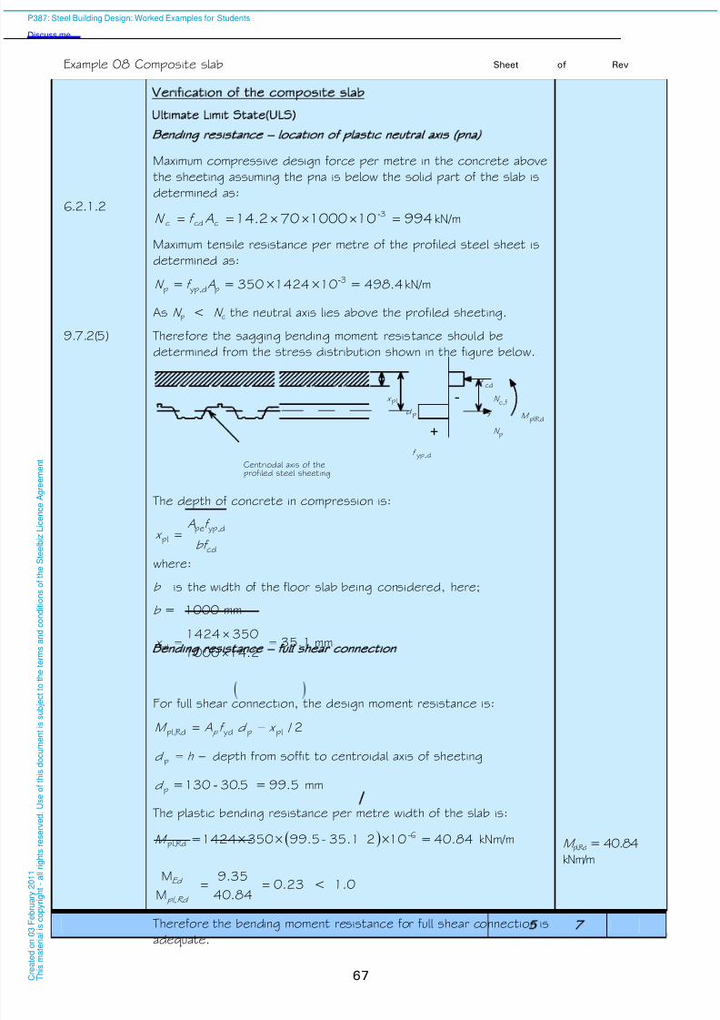
8/13/2019 p387 Calcul Imbinari in Engleza
http://slidepdf.com/reader/full/p387-calcul-imbinari-in-engleza 73/105
Example 08 Composite slab Sheet 5 of 7 Rev
67
6.2.1.2
Verification of the composite slab
Ultimate Limit State ULS)
Bending resistance – location of plastic neutral axis pna)
Maximum compressive design force per metre in the concrete above
the sheeting assuming the pna is below the solid part of the slab isdetermined as:
994101000702.14 3ccdc -Af N kN/m
Maximum tensile resistance per metre of the profiled steel sheet is
determined as:
4.498=10×1424×350== 3pdyp,p
-Af N kN/m
As N p < N c the neutral axis lies above the profiled sheeting.
9.7.2(5) Therefore the sagging bending moment resistance should be
determined from the stress distribution shown in the figure below.
+
-
Centriodal axis of theprofiled steel sheeting
cd
pl
yp,d
p
c,f
plRdz
x N
N
f
f
M pd
The depth of concrete in compression is:
cd
dyp,pe
plbf
f A
x
where:
b is the width of the floor slab being considered, here;
b = 1000 mm
1.352.141000
3501424pl
x mm
Bending resistance – full shear connection
For full shear connection, the design moment resistance is:
2 /plpydRdpl, x d f AM p
h d p depth from soffit to centroidal axis of sheeting
5.99=530130=p .d - mm
The plastic bending resistance per metre width of the slab is:
40.84=10×235.1-99.5×350×1424= 6Rdpl,
-M kNm/m M pl,Rd = 40.84
kNm/m
23.084.40
35.9
M
M
pl,Rd
Ed
< 1.0
Therefore the bending moment resistance for full shear connection is
adequate.
P387: Steel Building Design: Worked Examples for Students
Discuss me ...
C r e a
t e d o n
0 3 F e
b r u a r y
2 0 1 1
T h i s m a
t e r i a
l i s c o p y r i g h
t - a
l l r i g
h t s r e s e r v e
d .
U s e o
f t h i s d o c u m e n
t i s s u
b j e c
t t o t h e
t e r m s a n
d c o n
d i t i o n s o
f t h e
S t e e
l b i z
L i c e n c e
A g r e e m e n
t

8/13/2019 p387 Calcul Imbinari in Engleza
http://slidepdf.com/reader/full/p387-calcul-imbinari-in-engleza 74/105
Example 08 Composite slab Sheet 6 of 7 Rev
68
9.7.3 Longitudinal shear resistance: m-k method
The method given in 9.7.3 may be used to determine the design
resistance to longitudinal shear (V l,Rd). In this example, the benefits
of end anchorage have been ignored.
9.7.3(4)
k
bL mAbd V
s
p
vs
pRdl,
m and k are design values obtained from the manufacturer. For the
CF60 steel deck the following values have been obtained from the
output from the software Comdek .2)
m = 157.2 N/mm2
k = 0.1232 N/mm2
9.7.3(5) For a uniform load applied to the whole span length;
L s = 7504
3000
4
L mm
9.7.3(4)V l,Rd = 3101232.0
7501000
14242.157
25.1
5.991000-
= 33.56 kN/m
V Ed = 13.07 kN/m
The design shear resistance must not be less than the maximum
design vertical shear.
39.056.33
07.13
Rdl,
Ed V
V < 1.0
Therefore the design resistance to longitudinal shear is adequate.
Design vertical shear resistance
The vertical shear resistance will normally be based on BS EN 1992-
1-1 Equation 6.2b. Using the nomenclature in BS EN 1994-1-1, the
equation becomes:
pscp1minRdv, d b k v V
Although in reality the slab is continuous, it is normally convenient to
design it as simply supported (except for the fire condition when thebenefits of continuity are usually recognised). As a consequence of
this, the beneficial effect of the hogging moments at the supports is
neglected, such that 0cp . Hence,
psminRdv, d b v V
2) If the m and k values are not available from the manufacturer, the longitudinal shear for slabs without end
anchorage may be determined using the partial connection method given in 9.7.3(8) of BS EN 1994-1-1,
which requires the shear bond values
P387: Steel Building Design: Worked Examples for Students
Discuss me ...
C r e a
t e d o n
0 3 F e
b r u a r y
2 0 1 1
T h i s m a
t e r i a
l i s c o p y r i g h
t - a
l l r i g
h t s r e s e r v e
d .
U s e o
f t h i s d o c u m e n
t i s s u
b j e c
t t o t h e
t e r m s a n
d c o n
d i t i o n s o
f t h e
S t e e
l b i z
L i c e n c e
A g r e e m e n
t
8/13/2019 p387 Calcul Imbinari in Engleza
http://slidepdf.com/reader/full/p387-calcul-imbinari-in-engleza 75/105
Example 08 Composite slab Sheet 7 of 7 Rev
69
BS EN 1992-
1-1
NA 2
Table NA.1
The recommended value of v min is
21
ck 2
3
min 035.0 f k v
where k = 0.22001 p d
42.25.992001 , so k = 2.0
49.0252035.0 21
23
min v N/mm2
5.9949.0Rdv, V = 48.8 kN/m, > 13.19 kN/m , OK
Therefore the vertical shear resistance is satisfactory.
All design checks of the composite slab in the ultimate limit state are
satisfied.
Serviceability limit state SLS):
The serviceability limit state checks for the composite slab are not
given in this example. Some notes are given below.
9.8.1 (2) Cracking of concrete
As the slab is designed as being simply supported, only anti-crack
reinforcement is needed. The cross-sectional area of the
reinforcement (As) above the ribs of the profiled steel sheeting
should not be less than 0.4% of the cross-sectional area of the
concrete above the ribs for unpropped construction. Crack widths
may still need to be verified in some circumstances.
9.8.2(5)
Deflection:
For an internal span of a continuous slab the vertical deflection may
be determined using the following approximations:
• the second moment of area may be taken as the average of the
values for the cracked and un-cracked section;
• for concrete, an average value of the modular ratio, n , for both
long-term and short-term effects may be used.
Fire
This example has not considered fire resistance, which will sometimes
govern the design
P387: Steel Building Design: Worked Examples for Students
Discuss me ...
C r e a
t e d o n
0 3 F e
b r u a r y
2 0 1 1
T h i s m a
t e r i a
l i s c o p y r i g h
t - a
l l r i g
h t s r e s e r v e
d .
U s e o
f t h i s d o c u m e n
t i s s u
b j e c
t t o t h e
t e r m s a n
d c o n
d i t i o n s o
f t h e
S t e e
l b i z
L i c e n c e
A g r e e m e n
t

8/13/2019 p387 Calcul Imbinari in Engleza
http://slidepdf.com/reader/full/p387-calcul-imbinari-in-engleza 76/105
8/13/2019 p387 Calcul Imbinari in Engleza
http://slidepdf.com/reader/full/p387-calcul-imbinari-in-engleza 77/105
Job No. Sheet 1 of 11 Rev C
Job Title Example no. 09 Revised by DGB, April 09
Subject Bracing and bracing connections
Made by JPR Date Nov 2006
Silwood Park, Ascot, Berks SL5 7QN
Telephone: (01344) 636525
Fax: (01344) 636570
CALCULATION SHEET
Client
Checked by AGK Date Dec 2006
71
PUnless stated
otherwise all
references are
to BS EN
1993-1-1
Bracing and bracing connections
Design summary:
(a) The wind loading at each floor is transferred to two vertically
braced end bays on grid lines ‘A’ and ‘J’ by the floors acting as
diaphragms.
(b) The bracing system must carry the equivalent horizontal forces
(EHF) in addition to the wind loads.
(c) Locally, the bracing must carry additional loads due to
imperfections at splices (cl 5.3.3(4)) and restraint forces (cl
5.3.2(5)). These imperfections are considered in turn in
conjunction with external lateral loads but not at the same time
as the EHF.
(d) The braced bays, acting as vertical pin-jointed frames, transfer
the horizontal wind load to the ground.
(e) The beams and columns that make up the bracing system have
already been designed for gravity loads1). Therefore, only the
diagonal members have to be designed and only the forces in
these members have to be calculated.
(f) All the diagonal members are of the same section, thus, only themost heavily loaded member has to be designed.
Forces in the bracing system
BS EN
1991-1-4
Total overall unfactored wind load 2), F w = 925 kN
With two braced bays, total unfactored load to be resisted by each
braced bay = 0.5 × 925 = 463 kN
Actions
Roof
Permanent action = 0.9 kN/m2
Variable action = 0.6 kN/m2
Floor
Permanent action = 3.7 kN/m2
Variable action = 3.3 kN/m2
1) It should be checked that these members can also carry any loads imposed by the wind when they form part
of the bracing system, considering the appropriate combination of actions.
2) In this example, the wind load considered is only for the direction shown on structural arrangement and
loading, Sheet 2. In practice, other directions must also be considered.
P387: Steel Building Design: Worked Examples for Students
Discuss me ...
C r e a
t e d o n
0 3 F e
b r u a r y
2 0 1 1
T h i s m a
t e r i a
l i s c o p y r i g h
t - a
l l r i g
h t s r e s e r v e
d .
U s e o
f t h i s d o c u m e n
t i s s u
b j e c
t t o t h e
t e r m s a n
d c o n
d i t i o n s o
f t h e
S t e e
l b i z
L i c e n c e
A g r e e m e n
t

8/13/2019 p387 Calcul Imbinari in Engleza
http://slidepdf.com/reader/full/p387-calcul-imbinari-in-engleza 78/105
Example 09 Bracing and bracing connections Sheet 2 of 11 Rev
72
Ultimate Limit State ULS)
BS EN 1990
NA 2.2.3.2
Table
NA.A1.2(B)
Partial factors for actions
Partial factor for permanent actions G = 1.35
Partial factor for variable actions Q = 1.5
Reduction factor = 0.925
BS EN 1990
NA 2.2.2
Table NA.A1.1
0 factors
For imposed floor loads (office areas) 0 = 0.7
For snow loads on roofs (H 1000m a.s.l) 0 = 0.5
Combinations of actions for ULS, using Eqn 6.10b
Design value of combined actions
= k 0k Qk G Q Q G Q
In this example, the bracing will be verified for one design case,
using Equation 6.10b, with wind as the leading variable action. The
Equivalent horizontal forces (EHF) will also be calculated for this
combination. In practice, Equation 6.10a should also be checked,
and additional combinations (for example with the imposed floor load
as the leading variable action).
Design wind load at ULS
Using Equation 6.10b with wind as the leading variable action, the
design wind load per braced bay is:
6954631.5Ed F kN
Distributing this total horizontal load as point loads at roof and floor
levels, in proportion to the storey heights:
Roof level 856955.18
25.2 kN
3rd & 2nd floor levels 1696955.18
5.4 kN
1st floor level 1786955.18
75.4 kN
Ground at column base level 946955.18
5.2 kN*
*Assume that this load is taken out in shear through the ground slab
and is therefore not carried by the frame.
P387: Steel Building Design: Worked Examples for Students
Discuss me ...
C r e a
t e d o n
0 3 F e
b r u a r y
2 0 1 1
T h i s m a
t e r i a
l i s c o p y r i g h
t - a
l l r i g
h t s r e s e r v e
d .
U s e o
f t h i s d o c u m e n
t i s s u
b j e c
t t o t h e
t e r m s a n
d c o n
d i t i o n s o
f t h e
S t e e
l b i z
L i c e n c e
A g r e e m e n
t

8/13/2019 p387 Calcul Imbinari in Engleza
http://slidepdf.com/reader/full/p387-calcul-imbinari-in-engleza 79/105
Example 09 Bracing and bracing connections Sheet 3 of 11 Rev
73
Equivalent horizontal forces
With wind as the leading variable action, the design values of the
combined floor and roof actions are:
Design value for combined roof actions
= 0.925 ×1.35 × 0.9 + 1.5 × 0.5 × 0.6 = 1.57 kN/m2
Design value for combined floor actions
= 0.925 ×1.35 × 3.7 + 1.5 × 0.7 × 3.3 = 8.09 kN/m2
Total roof load = 1.57 × 14 × 48 = 1055 kN
Total floor load = 8.09 × 14 × 48 = 5437 kN
Equivalent horizontal forces for each bracing system are:
roof level = 0.5×200
1055 = 2.64 kN
floor level = 0.5×200
5437 = 13.6 kN
BS EN 1993-
1-1
5.3.2(3)
The equivalent horizontal forces have been based on 0 = 1/200.
The h and m factors have not been used, which is conservative.
Use of the h and m factors will reduce the forces in the bracing.
Horizontal forces at ground level
Horizontal design force due to wind
= (85 + 169 +169 + 178) = 601 kN
Horizontal design force due to equivalent horizontal loads
= 2.64 + 3×13.6 = 43.4 kN
Total horizontal design force per bracing system
= 601 + 43.4 = 644.4 kN
A computer analysis of the bracing system can be performed to
obtain the member forces. Alternatively, hand calculations can be
carried out to find the member forces. Simply resolving forces
horizontally at ground level is sufficient to calculate the force in the
lowest (most highly loaded) bracing member, as shown in Figure 9.1.
6 m
5 m
644.4
537.0
644.4
8 3 9
Figure 9.1 Lowest bracing
Horizontal component of force in
bracing member = 644.4 kN
Vertical component of force in
bracing member =
537.0=5×6
644.4 kN
Axial force in bracing =
22 537.0+644.4 = 839 kN
P387: Steel Building Design: Worked Examples for Students
Discuss me ...
C r e a
t e d o n
0 3 F e
b r u a r y
2 0 1 1
T h i s m a
t e r i a
l i s c o p y r i g h
t - a
l l r i g
h t s r e s e r v e
d .
U s e o
f t h i s d o c u m e n
t i s s u
b j e c
t t o t h e
t e r m s a n
d c o n
d i t i o n s o
f t h e
S t e e
l b i z
L i c e n c e
A g r e e m e n
t

8/13/2019 p387 Calcul Imbinari in Engleza
http://slidepdf.com/reader/full/p387-calcul-imbinari-in-engleza 80/105
Example 09 Bracing and bracing connections Sheet 4 of 11 Rev
74
Partial factors for resistance
NA 2.15
BS EN 1993-
1-8
NA 2.3 Table NA.1
M0 = 1.0
M1 = 1.0
M2 =1.25 (for bolts and welds)
Trial section
Try: 219.1 10.0 mm thick Circular Hollow Section (CHS), grade
S355
SCI P363 Section Properties
Area A = 65.7 cm²
Second moment of area I = 3600 cm4
Radius of gyration i = 7.40 cm
Thickness t = 10.0 mmRatio for local Buckling d /t = 21.9
Material properties
NA 2.4
BS EN
10210-1
Table A3
As t ≤ 16 mm, for S355 steel
Yield strength f y = 355 N/mm²
3.2.6 (1) modulus of elasticity E = 210 kN/mm²
5.5
Table 5.2
Section classification
Class 1 limit for section in compression, d /t ≤ 50
= (235/f y)0.5, f y = 355 N/mm², = 0.82
d /t ≤ 50e2 = 50×0.822 = 33.6
Since 21.9 < 33.6, the section is Class 1 for axial compression
Design of member in compression
Cross sectional resistance to axial compression
6.2.4(1)
Eq. 6.9Basic requirement 0.1
Rdc,
Ed N
N
6.2.4(2)
Eq. 6.10
N Ed is the design value of the applied axial force
N Ed = 839 kN
N c,Rd is the design resistance of the cross-section for uniform
compression
M0
y
Rdc,
f AN
(For Class 1, 2 and 3 cross-sections)
2332=10×1.0
355×6570 3c,Rd N kN
P387: Steel Building Design: Worked Examples for Students
Discuss me ...
C r e a
t e d o n
0 3 F e
b r u a r y
2 0 1 1
T h i s m a
t e r i a
l i s c o p y r i g h
t - a
l l r i g
h t s r e s e r v e
d .
U s e o
f t h i s d o c u m e n
t i s s u
b j e c
t t o t h e
t e r m s a n
d c o n
d i t i o n s o
f t h e
S t e e
l b i z
L i c e n c e
A g r e e m e n
t
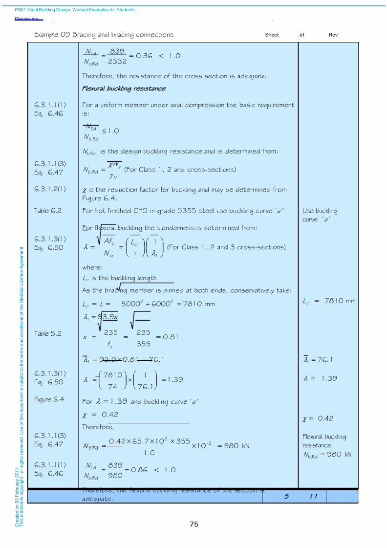
8/13/2019 p387 Calcul Imbinari in Engleza
http://slidepdf.com/reader/full/p387-calcul-imbinari-in-engleza 81/105
Example 09 Bracing and bracing connections Sheet 5 of 11 Rev
75
0.36=2332
839
Rdc,
Ed N
N < 1.0
Therefore, the resistance of the cross section is adequate.
Flexural buckling resistance6.3.1.1(1)
Eq. 6.46
For a uniform member under axial compression the basic requirement
is:
0.1Rdb,
Ed N
N
N b,Rd is the design buckling resistance and is determined from:
6.3.1.1(3)
Eq. 6.47M1
y
Rdb,
f AN (For Class 1, 2 and cross-sections)
6.3.1.2(1) is the reduction factor for buckling and may be determined fromFigure 6.4.
Table 6.2 For hot finished CHS in grade S355 steel use buckling curve ‘a’ Use buckling
curve ‘a’
For flexural buckling the slenderness is determined from:
6.3.1.3(1)
Eq. 6.50
1
cr
cr
y 1
i
L
N
Af (For Class 1, 2 and 3 cross-sections)
where:
L cr is the buckling length
As the bracing member is pinned at both ends, conservatively take:
L cr = L = 781060005000 22 mm L cr = 7810 mm
Table 5.2
9.931
0.81=355
235=
235
yf
76.1=0.81×93.9=1 1.761
6.3.1.3(1)
Eq. 6.50 39.11.76
1
74
7810
= 1.39
Figure 6.4 For 1.39= and buckling curve ‘a’
= 0.42 = 0.42
6.3.1.1(3)
Eq. 6.47
Therefore,
980=10×1.0
355×10×65.7×0.42= 3-
2
Rdb,N kN
Flexural buckling
resistance
980=Rdb,N kN
6.3.1.1(1)
Eq. 6.4686.0
980
839
Rdb,
Ed
N
N < 1.0
Therefore, the flexural buckling resistance of the section is
adequate.
P387: Steel Building Design: Worked Examples for Students
Discuss me ...
C r e a
t e d o n
0 3 F e
b r u a r y
2 0 1 1
T h i s m a
t e r i a
l i s c o p y r i g h
t - a
l l r i g
h t s r e s e r v e
d .
U s e o
f t h i s d o c u m e n
t i s s u
b j e c
t t o t h e
t e r m s a n
d c o n
d i t i o n s o
f t h e
S t e e
l b i z
L i c e n c e
A g r e e m e n
t
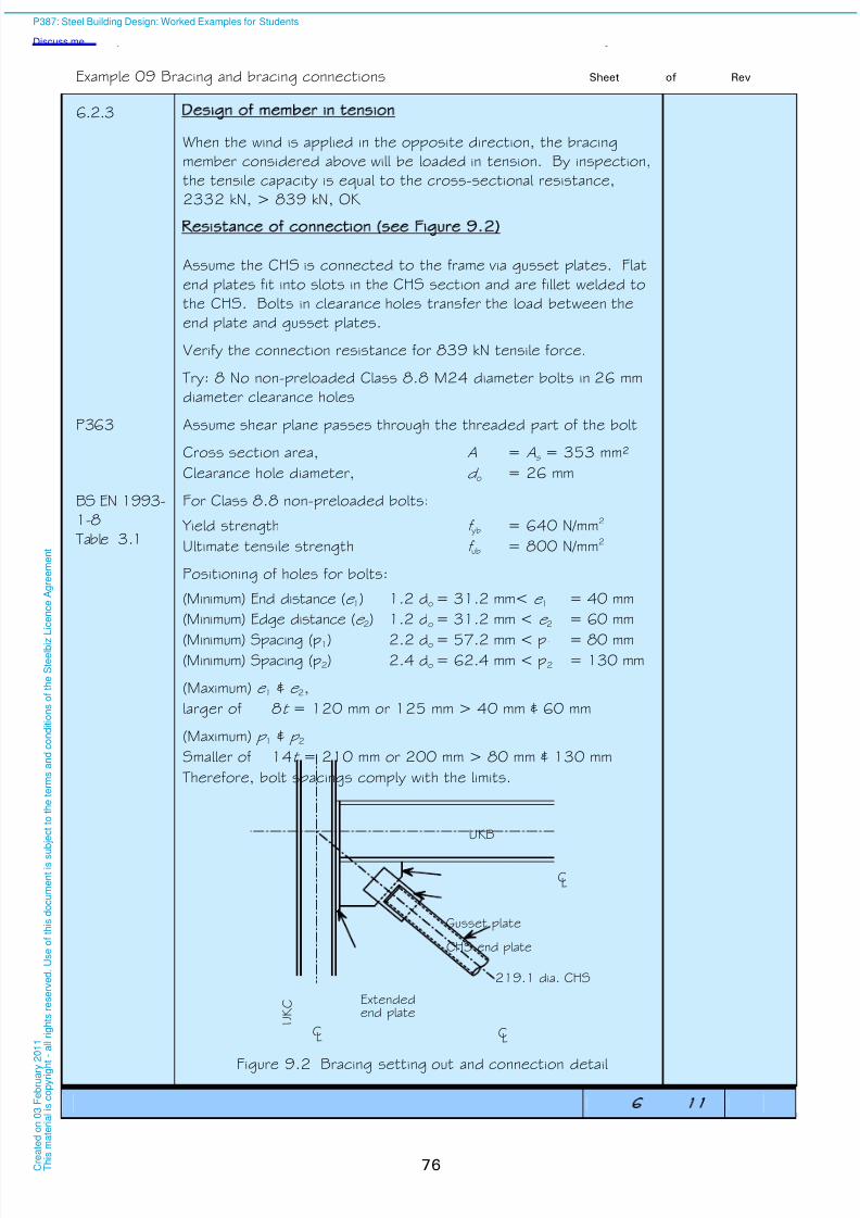
8/13/2019 p387 Calcul Imbinari in Engleza
http://slidepdf.com/reader/full/p387-calcul-imbinari-in-engleza 82/105
Example 09 Bracing and bracing connections Sheet 6 of 11 Rev
76
6.2.3 Design of member in tension
When the wind is applied in the opposite direction, the bracing
member considered above will be loaded in tension. By inspection,
the tensile capacity is equal to the cross-sectional resistance,
2332 kN, > 839 kN, OK
Resistance of connection see Figure 9.2)
Assume the CHS is connected to the frame via gusset plates. Flat
end plates fit into slots in the CHS section and are fillet welded to
the CHS. Bolts in clearance holes transfer the load between the
end plate and gusset plates.
Verify the connection resistance for 839 kN tensile force.
Try: 8 No non-preloaded Class 8.8 M24 diameter bolts in 26 mm
diameter clearance holes
P363 Assume shear plane passes through the threaded part of the bolt
Cross section area, A = As = 353 mm²
Clearance hole diameter, d o = 26 mm
BS EN 1993-
1-8
Table 3.1
For Class 8.8 non-preloaded bolts:
Yield strength f yb = 640 N/mm2
Ultimate tensile strength f ub = 800 N/mm2
Positioning of holes for bolts:
(Minimum) End distance (e 1) 1.2 do = 31.2 mm< e 1 = 40 mm
(Minimum) Edge distance (e 2) 1.2 do = 31.2 mm < e 2 = 60 mm
(Minimum) Spacing (p1) 2.2 do = 57.2 mm < p1 = 80 mm(Minimum) Spacing (p2) 2.4 do = 62.4 mm < p2 = 130 mm
(Maximum) e 1 & e 2,
larger of 8t = 120 mm or 125 mm > 40 mm & 60 mm
(Maximum) p 1 & p 2Smaller of 14t = 210 mm or 200 mm > 80 mm & 130 mm
Therefore, bolt spacings comply with the limits.
CL
CL CL
U K C
UKB
Extendedend plate
219.1 dia. CHS
Gusset plate
CHS end plate
Figure 9.2 Bracing setting out and connection detail
P387: Steel Building Design: Worked Examples for Students
Discuss me ...
C r e a
t e d o n
0 3 F e
b r u a r y
2 0 1 1
T h i s m a
t e r i a
l i s c o p y r i g h
t - a
l l r i g
h t s r e s e r v e
d .
U s e o
f t h i s d o c u m e n
t i s s u
b j e c
t t o t h e
t e r m s a n
d c o n
d i t i o n s o
f t h e
S t e e
l b i z
L i c e n c e
A g r e e m e n
t
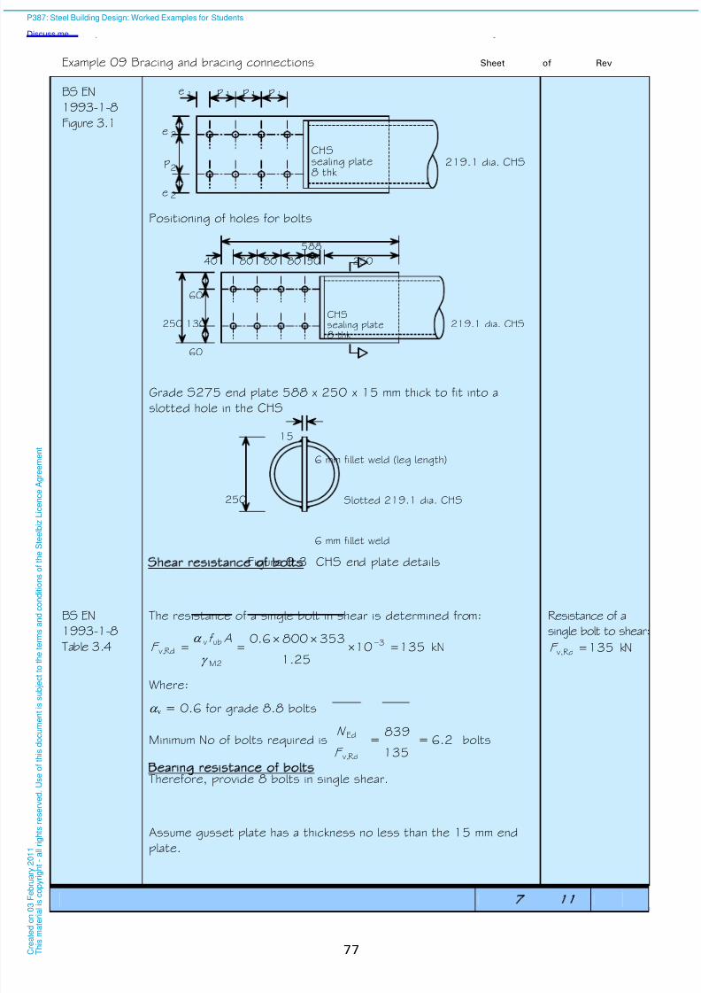
8/13/2019 p387 Calcul Imbinari in Engleza
http://slidepdf.com/reader/full/p387-calcul-imbinari-in-engleza 83/105
Example 09 Bracing and bracing connections Sheet 7 of 11 Rev
77
BS EN
1993-1-8
Figure 3.1
pp
219.1 dia. CHS
11 11
2
2
2
p
e
e
pe
CHSsealing plate
8 thk
Positioning of holes for bolts
40 8080 80
60
60
130250
50 250
219.1 dia. CHSCHSsealing plate8 thk
588
Grade S275 end plate 588 x 250 x 15 mm thick to fit into a
slotted hole in the CHS
15
250
6 mm fillet weld
Slotted 219.1 dia. CHS
6 mm fillet weld (leg length)
Figure 9.3 CHS end plate details
Shear resistance of bolts
BS EN
1993-1-8
Table 3.4
The resistance of a single bolt in shear is determined from:
1351025.1
3538006.0 3
M2
ubv Rdv,
Af F kN
Resistance of a
single bolt to shear:
135Rdv, F kN
Where:
v = 0.6 for grade 8.8 bolts
Minimum No of bolts required is 6.2=135
839=
Rdv,
Ed
F
N bolts
Therefore, provide 8 bolts in single shear.
Bearing resistance of bolts
Assume gusset plate has a thickness no less than the 15 mm end
plate.
P387: Steel Building Design: Worked Examples for Students
Discuss me ...
C r e a
t e d o n
0 3 F e
b r u a r y
2 0 1 1
T h i s m a
t e r i a
l i s c o p y r i g h
t - a
l l r i g
h t s r e s e r v e
d .
U s e o
f t h i s d o c u m e n
t i s s u
b j e c
t t o t h e
t e r m s a n
d c o n
d i t i o n s o
f t h e
S t e e
l b i z
L i c e n c e
A g r e e m e n
t

8/13/2019 p387 Calcul Imbinari in Engleza
http://slidepdf.com/reader/full/p387-calcul-imbinari-in-engleza 84/105
Example 09 Bracing and bracing connections Sheet 8 of 11 Rev
78
BS EN 1993-
1-1
NA 2.4
BS EN
10025-2
Table 7
End plate is a grade S275 and as t ≤ 16 mm, for S275 steel
Yield strength f y = 275 N/mm²
as 3 ≤ t ≤ 100 mm;
Ultimate tensile strength f u = 410 N/mm²
BS EN
1993-1-8
Table 3.4
The bearing resistance of a single bolt is determined from:
M2
ub1Rdb,
dt f k F
b is the least value of d,u,p
ub
f
f and 1.0
For end bolts 51.0263
40
3o
1d
d
e
For inner bolts 78.04
1
263
80
4
1
3 o
1d
d
p
95.1410
800
pu,
ub f
f
Therefore:
For end bolts 51.0b
For inner bolts 78.0b
Conservatively consider 51.0b for each bolt. 51.0b
For edge bolts k 1 is the smaller of 7.18.2o
2 d
e or 2.5
8.47.126
608.2
For inner bolts k 1 is the smaller of 7.14.1o
2 d
p or 2.5
3.57.1
26
1304.1
Therefore:
For both end and inner bolts 5.21 k 5.21 k
The least bearing resistance of a single bolt in this connection is
thus:
1511025.1
152441051.05.2 3Rdb,
F kN 151Rdb, F kN
Resistance of all six bolts in bearing may be conservatively taken as:
1208=151×8=8 Rdb,F kN
Resistance of 8
bolts in bearing
1208 kN
P387: Steel Building Design: Worked Examples for Students
Discuss me ...
C r e a
t e d o n
0 3 F e
b r u a r y
2 0 1 1
T h i s m a
t e r i a
l i s c o p y r i g h
t - a
l l r i g
h t s r e s e r v e
d .
U s e o
f t h i s d o c u m e n
t i s s u b
j e c
t t o t h e
t e r m s a n
d c o n
d i t i o n s o
f t h e
S t e e
l b i z L i c e n c e
A g r e e m e n
t

8/13/2019 p387 Calcul Imbinari in Engleza
http://slidepdf.com/reader/full/p387-calcul-imbinari-in-engleza 85/105
Example 09 Bracing and bracing connections Sheet 9 of 11 Rev
79
BS EN
1993-1-8
3.7
Group of fasteners
Because the shear resistance of the bolts (135 kN) is less than the
minimum bearing resistance of any bolt (151 kN), the design
resistance of the group is taken as:
8 × 135 = 1080 kN
Resistance of the
bolt group
1080 kN
Design of fillet weld see Figure 9.3)
BS EN
1993-1-8
4.5
Assume 6 mm leg length fillet weld is used on both sides, top and
bottom, of the fitted end plate. Use the simplified method in
4.5.3.3
BS EN
1993-1-8
4.5.3.3(3)
Design shear strength,M2w
udvw,
3 /
f f
BS EN
1993-1-8
Table 4.1
Correlation factor, for S275 steel w = 0.85
Throat thickness of weld
4.26.00.7lengthleg7.0 a mm
Therefore,
8.22225.185.0
3 /410dvw,
f N/mm2
BS EN
1993-1-8
4.5.3.3(2)
Design resistance of weld per unit length is:
8.9352.48.222dvw,dvw, a f F N/mm
See sheet 7 Hence, for four welds, each with an effective length of:
2380.62250eff l mm
the shear resistance is
891102388.93544 3effRdw, l F kN, > 839 kN, OK
Shear resistance of
4 by 238 mm long
6 mm fillet welds is:
891 kN
Local resistance of CHS wall
In the absence of guidance in BS EN 1993-1-1 for the shear area
of a plain rectangular area, it is assumed that the shear area,
Av = 0.9dt, where d is the depth of the rectangular area and
t the thickness.
Total shear area = 4 × 0.9 ×250 × 10 = 9000 mm2
Shear resistance isM0
yv 3
f A = 310×1.0
3355×900 = 1844 kN
1844 kN > 839 kN, OK
P387: Steel Building Design: Worked Examples for Students
Discuss me ...
C r e a
t e d o n
0 3 F e
b r u a r y
2 0 1 1
T h i s m a
t e r i a
l i s c o p y r i g h
t - a
l l r i g
h t s r e s e r v e
d .
U s e o
f t h i s d o c u m e n
t i s s u
b j e c
t t o t h e
t e r m s a n
d c o n
d i t i o n s o
f t h e
S t e e
l b i z
L i c e n c e
A g r e e m e n
t

8/13/2019 p387 Calcul Imbinari in Engleza
http://slidepdf.com/reader/full/p387-calcul-imbinari-in-engleza 86/105
Example 09 Bracing and bracing connections Sheet 10 of 11 Rev
80
Tensile resistance of end plate see Figure 9.4)
Two modes of failure are to be considered:
i) cross-sectional failure and
ii) block tearing failure.
BS EN1993-1-8
3.10.2 219.1 dia. CHSedNedN
i ) Cross-sectional failure
NN
219.1 dia. CHS
NN
219.1 dia. CHS
eded eded
ii ) Block tearing failure
Figure 9.4 Plate failure modes
6.2.3(1)
i Cross-sectional failure
Basic requirement: 0.1Rdt,
Ed N
N
6.2.3(2)
Eqn. 6.6
For a cross-section with holes, the design tensile resistance is
taken as the smaller of N pl,Rd and N u,Rd:
M0
y
Rdpl,
f A
N
A is the gross cross-sectional area:
375015250 A mm2
1031100.1
2753750 3Rdpl,
N kN, > 839 kN, OK
N pl,Rd = 1031kN
Eqn. 6.7
M2
unetu,Rd
9.0
f AN
6.2.2.2 2970152623750net A mm2
8761025.1
41029709.0 3Rdu,
N kN, > 839 kN, OK
N u,Rd = 876 kN
ii Block tearing failure
BS EN
1993-1-8
3.10.2 (2)
For a symmetric bolt group subject to concentric loading, the
design block tearing resistance ( RdEff,1,V ) is determined from:
M0
nv y
M2
ntuRdeff,1, 3 /1
Af Af V
where:
ntA is the net area subject to tension
nv A is the net area subject to shear
P387: Steel Building Design: Worked Examples for Students
Discuss me ...
C r e a
t e d o n
0 3 F e
b r u a r y
2 0 1 1
T h i s m a
t e r i a
l i s c o p y r i g h
t - a
l l r i g
h t s r e s e r v e
d .
U s e o
f t h i s d o c u m e n
t i s s u
b j e c
t t o t h e
t e r m s a n
d c o n
d i t i o n s o
f t h e
S t e e
l b i z
L i c e n c e
A g r e e m e n
t

8/13/2019 p387 Calcul Imbinari in Engleza
http://slidepdf.com/reader/full/p387-calcul-imbinari-in-engleza 87/105
Example 09 Bracing and bracing connections Sheet 11 of 11 Rev
81
ntA is minimum of ( p 2 – d o) t p and 2 (ez – 0.5 d o) t p
( p 2 – d o) t p = (130 – 26) × 15 = 1560 mm2
2 (e 2 – 0.5 d o) t p = 2 (60 -13) × 15 = 1410 mm2
Ant = 1410 mm2
6450=15×215×2=)2.5+2(3= w011nv t d e p A mm2
1487=10×1.0
6450×275×31/+
10×1.25
1410×410V
331 ,Rd eff, kN
1487 kN > 839 kN, OK
V Eff,1,Rd = 1487 kN
The gusset plates would also require checking for shear, bearing and
welds, together with full design check for the extended beam end
plates3).
3) The gusset plate must be checked for yielding across an effective dispersion width of the plate. When the
bracing member is in compression, buckling of the gusset plate must be prevented and therefore a full
desi n check must be carried out.
P387: Steel Building Design: Worked Examples for Students
Discuss me ...
C r e a
t e d o n
0 3 F e
b r u a r y
2 0 1 1
T h i s m a
t e r i a
l i s c o p y r i g h
t - a
l l r i g
h t s r e s e r v e
d .
U s e o
f t h i s d o c u m e n
t i s s u
b j e c
t t o t h e
t e r m s a n
d c o n
d i t i o n s o
f t h e
S t e e
l b i z
L i c e n c e
A g r e e m e n
t

8/13/2019 p387 Calcul Imbinari in Engleza
http://slidepdf.com/reader/full/p387-calcul-imbinari-in-engleza 88/105
82
P387: Steel Building Design: Worked Examples for Students
Discuss me ...
C r e a
t e d o n
0 3 F e
b r u a r y
2 0 1 1
T h i s m a
t e r i a
l i s c o p y r i g h
t - a
l l r i g
h t s r e s e r v e
d .
U s e o
f t h i s d o c u m e n
t i s s u
b j e c
t t o t h e
t e r m s a n
d c o n
d i t i o n s o
f t h e
S t e e
l b i z
L i c e n c e
A g r e e m e n
t

8/13/2019 p387 Calcul Imbinari in Engleza
http://slidepdf.com/reader/full/p387-calcul-imbinari-in-engleza 89/105
Job No. Sheet of 7 Rev C
Job Title Example no. 10 Revised by DGB, April 09
Subject Beam-to-column flexible end plate connection
Made by MS Date Nov 2006
Silwood Park, Ascot, Berks SL5 7QN
Telephone: (01344) 636525
Fax: (01344) 636570
CALCULATION SHEET
Client
Checked by PA Date Dec 2006
83
Beam-to-column flexible end plate connection
Design the beam-to-column connection at level 1 between gridlines
G and 2.
Unless stated
otherwise all
references are
to BS EN
1993-1-
8:2005
BS EN
1993-1-1
NA 2.4
BS EN
10025-2
Table 7
BS EN 1993-
1-1
NA 2.15
Initial sizing of the components of the connection
Column 254 × 254 × 73 UKC in S275 steel
Beam 457 × 191 × 82 UKB in S275 steel
For the beam, f y = 275 N/mm2; f u = 410 N/mm2; h b = 460mm;
t w = 9.9mm; t f = 16mm
For the plate, f u = 410 N/mm2
V cRd ≈ M0
3th
y w b
f
=3100.1
32759.9460
= 723kN
From example 1 the design shear force at ULS,V Ed = 230 kN V Ed = 230 kN
Access steel
documentSN013a-EN-
EU
Because 230 < 0.75V cRd , a partial depth endplate is proposed.
h b < 500 mm, so 8 or 10 mm endplate is proposed.
End plate depth is minimum 0.6 h b = 276 mm; propose 280 mm.
Assuming M20 bolts, number of bolts = 239/74 = 3.2
6 M20 bolts are proposed.
Based on the above, the initial sizing of the connection components
is shown in Figure 10.1.
a
p
p
e
e
h
e
e
g
m
p 2c
2p
3
1
1
1
1
v
p
100 77
50
50
55
55
85
85
280
a = 4 mm
6 No. M20 8.8 bolts
(a) parameters definition (b) Profile adopted based on initial sizing
Figure 10.1 Connection details
P387: Steel Building Design: Worked Examples for Students
Discuss me ...
C r e a
t e d o n
0 3 F e
b r u a r y
2 0 1 1
T h i s m a
t e r i a
l i s c o p y r i g h
t - a
l l r i g
h t s r e s e r v e
d .
U s e o
f t h i s d o c u m e n
t i s s u
b j e c
t t o t h e
t e r m s a n
d c o n
d i t i o n s o
f t h e
S t e e
l b i z
L i c e n c e
A g r e e m e n
t
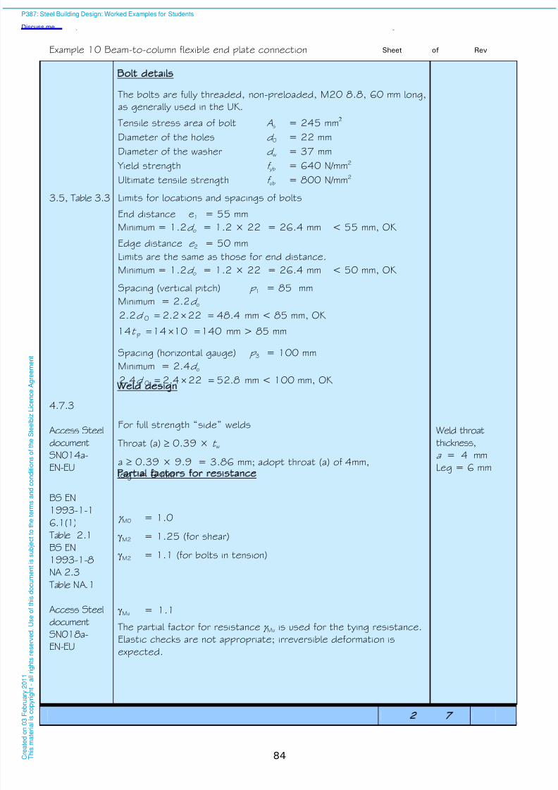
8/13/2019 p387 Calcul Imbinari in Engleza
http://slidepdf.com/reader/full/p387-calcul-imbinari-in-engleza 90/105
Example 10 Beam-to-column flexible end plate connection Sheet 2 of 7 Rev
84
Bolt details
The bolts are fully threaded, non-preloaded, M20 8.8, 60 mm long,
as generally used in the UK.
Tensile stress area of bolt As = 245 mm2
Diameter of the holes d 0 = 22 mmDiameter of the washer d w = 37 mm
Yield strength f yb = 640 N/mm2
Ultimate tensile strength f ub = 800 N/mm2
3.5, Table 3.3 Limits for locations and spacings of bolts
End distance e1 = 55 mm
Minimum = 1.2d o = 1.2 × 22 = 26.4 mm < 55 mm, OK
Edge distance e 2 = 50 mm
Limits are the same as those for end distance.
Minimum = 1.2d o = 1.2 × 22 = 26.4 mm < 50 mm, OK
Spacing (vertical pitch) p 1 = 85 mm
Minimum = 2.2d o4.48222.22.2 0 d mm < 85 mm, OK
140101414 p t mm > 85 mm
Spacing (horizontal gauge) p 3 = 100 mm
Minimum = 2.4d o
8.52224.22.4 0 d mm < 100 mm, OK
4.7.3
Access Steel
document
SN014a-
EN-EU
Weld design
For full strength “side” welds
Throat (a) 0.39 × t w
a 0.39 × 9.9 = 3.86 mm; adopt throat (a) of 4mm,
leg = 6 mm
Weld throat
thickness,
a = 4 mm
Leg = 6 mm
BS EN
1993-1-1
6.1(1)
Table 2.1
BS EN1993-1-8
NA 2.3
Table NA.1
Partial factors for resistance
M0 = 1.0
M2 = 1.25 (for shear)
M2 = 1.1 (for bolts in tension)
Access Steel
document
SN018a-
EN-EU
Mu = 1.1
The partial factor for resistance Mu is used for the tying resistance.
Elastic checks are not appropriate; irreversible deformation is
expected.
P387: Steel Building Design: Worked Examples for Students
Discuss me ...
C r e a
t e d o n
0 3 F e
b r u a r y
2 0 1 1
T h i s m a
t e r i a
l i s c o p y r i g h
t - a
l l r i g
h t s r e s e r v e
d .
U s e o
f t h i s d o c u m e n
t i s s u
b j e c
t t o t h e
t e r m s a n
d c o n
d i t i o n s o
f t h e
S t e e
l b i z
L i c e n c e
A g r e e m e n
t

8/13/2019 p387 Calcul Imbinari in Engleza
http://slidepdf.com/reader/full/p387-calcul-imbinari-in-engleza 91/105
Example 10 Beam-to-column flexible end plate connection Sheet 3 of 7 Rev
85
The connection detail must be ductile to meet the design
requirement that it behaves as nominally pinned. For the UK, and
based on SN014, the ductility requirement is satisfied if the
supporting element (column flange in this case) or the end plate,
complies with the following conditions:
SN014a-
EN-EU
py,
bu,
p
8.2 f
f d t ≤ or
cy,
bu,
cf,
8.2 f
f d t ≤
12275
800
8.2
20
8.2 py,
bu,
f
f d mm
Since t p = 10 mm < 12 mm, ductility is ensured.
Joint shear resistance
The following table gives the complete list of design resistances that
need to be determined for the joint shear resistance. Only the
critical checks are shown in this example. The critical checks are
denoted with an * in the table. Because a full strength weld has been
provided, no calculations for the weld are required.
Mode of failure
Bolts in shear* V Rd,1
End plate in bearing* V Rd,2
Supporting member (column) in bearing V Rd,3
End plate in shear (gross section) V Rd,4
End plate in shear (net section) V Rd,5
End plate in block shear V Rd,6
End plate in bending V Rd,7
Beam web in shear* V Rd,8
3.6.1 &
Table 3.4Bolts in shear
Assuming the shear plane passes through the threaded portion of
the bolt, the shear resistance F v,Rd of a single bolt is given by:
M2
ubv Rdv,
Af F
Access Steel
document
SN014a-EN-
EU
Although not required by the Eurocode, a factor of 0.8 is
introduced into the above equation, to allow for the presence of
modest tension (not calculated) in the bolts.
For bolt class 8.8, v = 0.6, therefore,
2.571.25
102458000.6
8.0
-3
Rdv,
F kN
For 6 bolts, V Rd,1= 6 × 75.2 = 451 kN V Rd,1 = 451 kN
P387: Steel Building Design: Worked Examples for Students
Discuss me ...
C r e a
t e d o n
0 3 F e
b r u a r y
2 0 1 1
T h i s m a
t e r i a
l i s c o p y r i g h
t - a
l l r i g
h t s r e s e r v e
d .
U s e o
f t h i s d o c u m e n
t i s s u
b j e c
t t o t h e
t e r m s a n
d c o n
d i t i o n s o
f t h e
S t e e
l b i z
L i c e n c e
A g r e e m e n
t
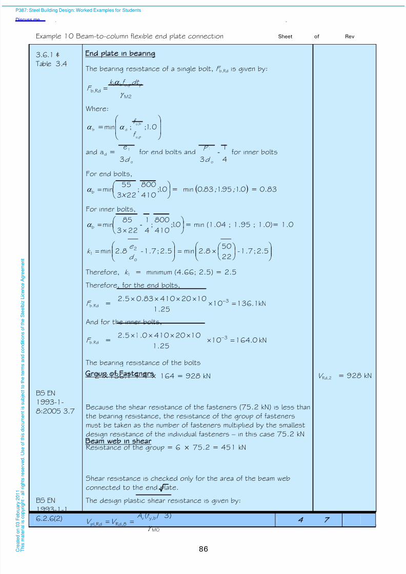
8/13/2019 p387 Calcul Imbinari in Engleza
http://slidepdf.com/reader/full/p387-calcul-imbinari-in-engleza 92/105
Example 10 Beam-to-column flexible end plate connection Sheet 4 of 7 Rev
86
3.6.1 &
Table 3.4End plate in bearing
The bearing resistance of a single bolt, F b,Rd is given by:
M2
ppu,b1
b,Rd
dt f k F
Where:
01;;min=
pu,
bu,
db .f
f
and ad =o
1
3
e
d for end bolts and
4
1
3 o
1-
d
p for inner bolts
For end bolts,
01;
410
800;
223
55minb .
× = 01951830min .; .; . = 0.83
For inner bolts,
01;
410
800;
4
1
223
85minb .- = min (1.04 ; 1.95 ; 1.0)= 1.0
2.5;1.7-
22
508.2min2.5;1.7-8.2min
o
21
d
e k
Therefore, k 1 = minimum (4.66; 2.5) = 2.5
Therefore, for the end bolts,
F b.Rd = kN1.1361025.1
102041083.05.2 3
And for the inner bolts,
F b.Rd = kN0.1641025.1
10204100.15.2 3
The bearing resistance of the bolts
= 2 ×136.1 + 4 × 164 = 928 kN V Rd,2 = 928 kN
BS EN
1993-1-8:2005 3.7
Group of Fasteners
Because the shear resistance of the fasteners (75.2 kN) is less than
the bearing resistance, the resistance of the group of fasteners
must be taken as the number of fasteners multiplied by the smallest
design resistance of the individual fasteners – in this case 75.2 kN
Resistance of the group = 6 × 75.2 = 451 kN
Beam web in shear
Shear resistance is checked only for the area of the beam web
connected to the end plate.
BS EN1993-1-1
6.2.6(2)
The design plastic shear resistance is given by:
M0
by,v
Rd,8Rdpl,
)3 /(
f AV V
P387: Steel Building Design: Worked Examples for Students
Discuss me ...
C r e a
t e d o n
0 3 F e
b r u a r y
2 0 1 1
T h i s m a
t e r i a
l i s c o p y r i g h
t - a
l l r i g
h t s r e s e r v e
d .
U s e o
f t h i s d o c u m e n
t i s s u
b j e c
t t o t h e
t e r m s a n
d c o n
d i t i o n s o
f t h e
S t e e
l b i z
L i c e n c e
A g r e e m e n
t

8/13/2019 p387 Calcul Imbinari in Engleza
http://slidepdf.com/reader/full/p387-calcul-imbinari-in-engleza 93/105
Example 10 Beam-to-column flexible end plate connection Sheet 5 of 7 Rev
87
Access Steel
document
SN014a-EN-
EU
A factor of 0.9 is introduced into the above equation when
calculating the plastic shear resistance of a plate (which is not
covered in BS EN 1993-1-1)
310
01
3275992809.0 ×
.
/ × .× = 396 kN VRd,8 = 396 kN
The design shear resistance of the connection is
396 kN, > 230 kN, OK
Tying resistance of end plate 1
The following table gives the complete list of design resistances that
need to be determined for the tying resistance of the end plate.
Only critical checks are shown. The critical checks are denoted with
an * in the table. The check for bolts in tension is also carried out
because the tension capacity of the bolt group is also needed for
the end plate in bending check.
Mode of failure
Bolts in tension N Rd,u,1
End plate in bending* N Rd,u,2
Supporting member in bending N Rd,u,3
Beam web in tension N Rd,u,4
Bolts in tension
3.6.1 &
Table 3.4
The tension resistance for a single bolt is given by:
Mu
sub2
Rdt,
Af k F
k 2 = 0.9
160.4101.1
2458000.9 3Rdt,u,1Rd,
F N kN
For 6 bolts, 962160.46u,1Rd, N kNN Rd,u,1 = 962 kN
End plate in bending
Equivalent tee-stub considered for the end plate in bending checks:
t
p
w,b
p
3
m
0.8a 2 a
1) The tying force to be resisted should be determined following the guidance in BS EN 1991-1-7 or the
applicable National Regulations i.e. Building Regulations.
P387: Steel Building Design: Worked Examples for Students
Discuss me ...
C r e a
t e d o n
0 3 F e
b r u a r y
2 0 1 1
T h i s m a
t e r i a
l i s c o p y r i g h
t - a
l l r i g
h t s r e s e r v e
d .
U s e o
f t h i s d o c u m e n
t i s s u
b j e c
t t o t h e
t e r m s a n
d c o n
d i t i o n s o
f t h e
S t e e
l b i z
L i c e n c e
A g r e e m e n
t

8/13/2019 p387 Calcul Imbinari in Engleza
http://slidepdf.com/reader/full/p387-calcul-imbinari-in-engleza 94/105
Example 10 Beam-to-column flexible end plate connection Sheet 6 of 7 Rev
88
6.2.4 &
Table 6.2
N Rd,u,2 = min (F Rd,u,ep1; F Rd,u,ep2)
For mode 1:)(n2
)2(8
ppwpp
Rdpl,1,wp
Rd T,1,ep1u,Rd,n m e m
M e n F F
For mode 2:pp
Rdt,pRdpl,2,Rd T,2,ep1u,Rd, 2
n m F n M F F
Where:
n p = min(e 2; e 2,c; 1.25m p)
m p =
2
20.82bw,3 a t p
e w =4
wd = 25.9
4
37 mm
(d w is the diameter of washer or width across points of bolt head ornut)
Here,
5.40
2
240.829.9-100p
m mm
7.505.4025.125.1 p m mm
n p = min (50; 77; 50.7) = 50 mm
M0
py,2peff,1
Rdpl,1,
ft
4
1M
∑
(Mode 1)
M0
py,2peff,2
Rdpl,2,
ft
4
1M
∑
(Mode 2)
Calculate the effective length of the end plate for mode 1 ∑ eff,1
and mode 2 ∑ eff,2 .
6.2.6.5 &
Table 6.6
For simplicity, the effective length of the equivalent tee stub, l eff i s
taken as the length of the plate, i.e. 280 mm
Therefore, eff,1 = eff,2 = h p = 280 mm
Mu
pu,
2
pp
uRd,pl,1,
4
1
f t h M
2.61101.1
10410280
4
1 62
uRd,pl,1,
M kNm
Mode 1:
310505.40259505.402
1061.22592508F
3
Rd T,1,
.
.= kN
P387: Steel Building Design: Worked Examples for Students
Discuss me ...
C r e a
t e d o n
0 3 F e
b r u a r y
2 0 1 1
T h i s m a
t e r i a
l i s c o p y r i g h
t - a
l l r i g
h t s r e s e r v e
d .
U s e o
f t h i s d o c u m e n
t i s s u
b j e c
t t o t h e
t e r m s a n
d c o n
d i t i o n s o
f t h e
S t e e
l b i z
L i c e n c e
A g r e e m e n
t
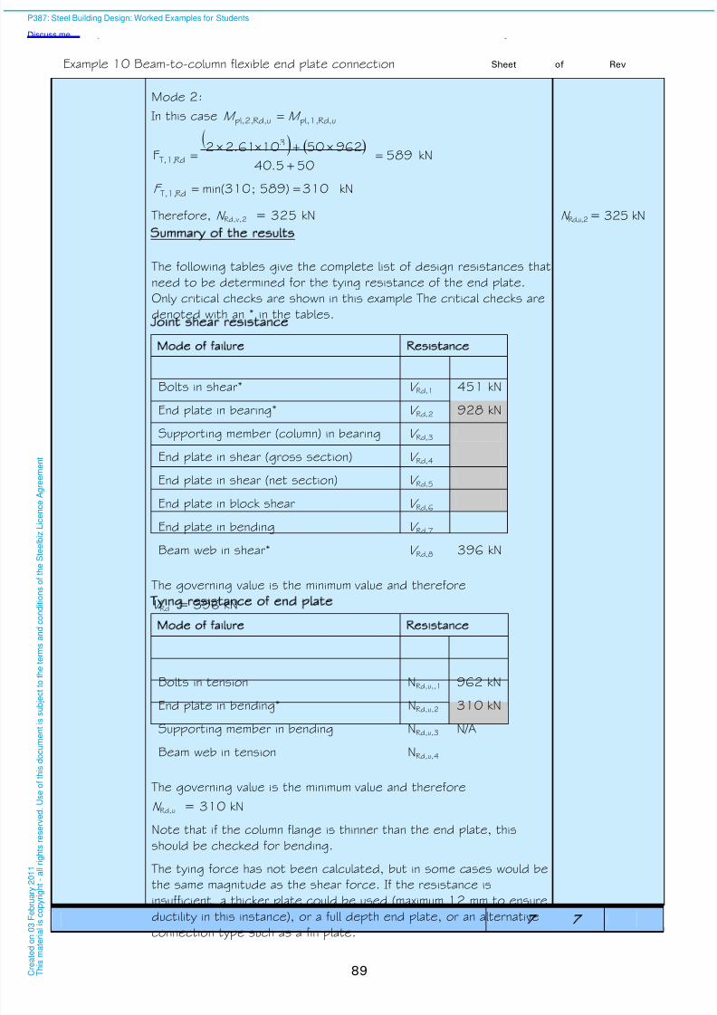
8/13/2019 p387 Calcul Imbinari in Engleza
http://slidepdf.com/reader/full/p387-calcul-imbinari-in-engleza 95/105
Example 10 Beam-to-column flexible end plate connection Sheet 7 of 7 Rev
89
Mode 2:
In this case uRd,pl,1,uRd,pl,2, M M
589
505.40
962501061.22F
3
Rd T,1,
kN
1039)85;min(310Rd T,1, F kN
Therefore, N Rd,v,2 = 325 kN N Rd,u,2= 325 kN
Summary of the results
The following tables give the complete list of design resistances that
need to be determined for the tying resistance of the end plate.
Only critical checks are shown in this example The critical checks are
denoted with an * in the tables.
Joint shear resistance
Mode of failure Resistance
Bolts in shear* V Rd,1 451 kN
End plate in bearing* V Rd,2 928 kN
Supporting member (column) in bearing V Rd,3
End plate in shear (gross section) V Rd,4
End plate in shear (net section) V Rd,5
End plate in block shear V Rd,6
End plate in bending V Rd,7 Beam web in shear* V Rd,8 396 kN
The governing value is the minimum value and therefore
V Rd = 396 kN
Tying resistance of end plate
Mode of failure Resistance
Bolts in tension NRd,u,,1 962 kN
End plate in bending* NRd,u,2 310 kNSupporting member in bending NRd,u,3 N/A
Beam web in tension NRd,u,4
The governing value is the minimum value and therefore
N Rd,u = 310 kN
Note that if the column flange is thinner than the end plate, this
should be checked for bending.
The tying force has not been calculated, but in some cases would be
the same magnitude as the shear force. If the resistance isinsufficient, a thicker plate could be used (maximum 12 mm to ensure
ductility in this instance), or a full depth end plate, or an alternative
connection type such as a fin plate.
P387: Steel Building Design: Worked Examples for Students
Discuss me ...
C r e a
t e d o n
0 3 F e
b r u a r y
2 0 1 1
T h i s m a
t e r i a
l i s c o p y r i g h
t - a
l l r i g
h t s r e s e r v e
d .
U s e o
f t h i s d o c u m e n
t i s s u
b j e c
t t o t h e
t e r m s a n
d c o n
d i t i o n s o
f t h e
S t e e
l b i z
L i c e n c e
A g r e e m e n
t

8/13/2019 p387 Calcul Imbinari in Engleza
http://slidepdf.com/reader/full/p387-calcul-imbinari-in-engleza 96/105
90
P387: Steel Building Design: Worked Examples for Students
Discuss me ...
C r e a
t e d o n
0 3 F e
b r u a r y
2 0 1 1
T h i s m a
t e r i a
l i s c o p y r i g h
t - a
l l r i g
h t s r e s e r v e
d .
U s e o
f t h i s d o c u m e n
t i s s u
b j e c
t t o t h e
t e r m s a n
d c o n
d i t i o n s o
f t h e
S t e e
l b i z
L i c e n c e
A g r e e m e n
t

8/13/2019 p387 Calcul Imbinari in Engleza
http://slidepdf.com/reader/full/p387-calcul-imbinari-in-engleza 97/105
Job No. Sheet of 2 Rev C
Job Title Example no. 11 Revised by DGB, April 09
Subject Column base
Made by MC Date Apr 2007
Silwood Park, Ascot, Berks SL5 7QN
Telephone: (01344) 636525
Fax: (01344) 636570
CALCULATION SHEET
Client
Checked by KS Date May 2007
91
Column base connection
Design conditions for column G2
Unless stated
otherwise all
references are
to BS EN
1993-1-1
and its National
Annex
From previous calculations the following design forces should be
considered.
The column is assumed to be pin-ended. However it is crucial the
column is stable during the erection phase therefore 4 bolts outside
the column profile should be used.
z z
y
y
Figure 11.1 Plan of baseplate
Example 05 Characteristic force due to permanent action, FG ,k = 466 kNCharacteristic force due to variable action, FQ,k = 416 kN
Ultimate Limit State ULS)
Partial factors for actions
BS EN
1990-1-1
NA 2.2.3.2
Table NA
A1.2(B)
Partial factor for permanent action G = 1.35
Partial factor for variable action Q = 1.5
Reduction factor = 0.925
Combination of actions for ULSDesign value of combined actions
N Ed = 0.925 × 1.35 × 466 + 1.5 × 416 = 1206 kN Axial force
N Ed = 1206 kN
Column details
P 363 Column G2 is a typical internal column
Serial size 254 × 254 × 73 UKC in S275 steel
Height of section h = 254.1 mm
Breadth of section b = 254.6 mm
Thickness of flange t f = 14.2 mm Thickness of web t w = 8.6 mm
Cross sectional Area A = 93.1 cm2
Section perimeter = 1490 mm
P387: Steel Building Design: Worked Examples for Students
Discuss me ...
C r e a
t e d o n
0 3 F e
b r u a r y
2 0 1 1
T h i s m a
t e r i a
l i s c o p y r i g h
t - a
l l r i g
h t s r e s e r v e
d .
U s e o
f t h i s d o c u m e n
t i s s u
b j e c
t t o t h e
t e r m s a n
d c o n
d i t i o n s o
f t h e
S t e e
l b i z
L i c e n c e
A g r e e m e n
t

8/13/2019 p387 Calcul Imbinari in Engleza
http://slidepdf.com/reader/full/p387-calcul-imbinari-in-engleza 98/105
Example 11 Column base Sheet 2 of 2 Rev
92
Partial factors for resistance
NA 2.15 M0 = 1.0 M2 1.25
Base plate details
BS EN1992-1-1
Table 3.1
Strength of foundation concrete to be C25/30(i.e. f ck =30 N/mm2)
BS EN
1992-1-1
NA 2
Table NA 1
c
ck cccd
f f
cc to be taken as 0.85 for axial loading
BS EN
1992-1-1
NA 2
Table NA 1
C = 1.5
175.1
3085.0cd f N/mm2 f cd = 17 N/mm2
Area required = =17
101206 370941 mm2
Effective area ≈ 4c2 + Section perimeter × c + section area
where c is the cantilever outstand of the effective area, as shown
below.
70941 = 4c 2 + 1490c + 9310
Solving, c = 37.6mm
h + 2c
b + 2c
h - 2t -2cf
2
2 f t h
= 2
2.1421.254
= 112.9 mm,
> 37.6 mm
Therefore there is no overlap between the
flanges
Thickness of base plate tp)
BS EN
1993-1-8
6.2.5(4)
5.0
M0y
cdp
3
f f c t
2.160.1275
1736.37
5.0
p
t mm
t p < 40, therefore nominal design strength = 275 N/mm2.
Adopt 20mm thick base plate in S275 materialt p = 20 mm
Connection of base plate to co lumn
It is assumed that the axial force is transferred by direct bearing,
which is achieved by normal fabrication processes. Only nominalwelds are required to connect the baseplate to the column, though
in practice full profile 6mm fillet welds are often used.
P387: Steel Building Design: Worked Examples for Students
Discuss me ...
C r e a
t e d o n
0 3 F e
b r u a r y
2 0 1 1
T h i s m a
t e r i a
l i s c o p y r i g h
t - a
l l r i g
h t s r e s e r v e
d .
U s e o
f t h i s d o c u m e n
t i s s u
b j e c
t t o t h e
t e r m s a n
d c o n
d i t i o n s o
f t h e
S t e e
l b i z
L i c e n c e
A g r e e m e n
t

8/13/2019 p387 Calcul Imbinari in Engleza
http://slidepdf.com/reader/full/p387-calcul-imbinari-in-engleza 99/105
Job No. Sheet of 4 Rev C
Job Title Example no. 12 Revised by DGB, April 09
Subject Frame stability
Made by KP Date Dec 2007
Silwood Park, Ascot, Berks SL5 7QN
Telephone: (01344) 636525
Fax: (01344) 636570
CALCULATION SHEET
Client
Checked by BD Date Dec 2007
93
Frame stability
Introduction
Unless stated
otherwise all
references are
to BS EN
1993-1-1
This example examines the building for susceptibility to sway
instability (second-order effects). Beam-and-column type plane
frames in buildings may be checked for susceptibility to second
order effects using first order analysis and the approximate formula:
5.2.1(4)B
EdH,Ed
Edcr =
h
V
H If acr 10, any second-order effects are small enough to be
ignored. The definition of each parameter is given later in this
example.
Figure 12.1 shows the structural layout of the braced bays which
are present in each end gable of the building. Unbraced bays occur
at 6 m spacing along the 48 m length of the building (i.e. 8 bays in
total). The braced bay therefore attracts one half of the total wind
loading on the windward face of the building which is assumed to be
transferred to the bracing via a wind girder in the roof anddiaphragm action in the floor slabs at each floor level.
The bracing must also carry the equivalent horizontal forces that
arise from frame imperfections such as a lack of verticality. The
equivalent imperfection forces are based on 1/200 (0.5%) of the
total factored permanent and variable load acting on each roof and
floor level. These imperfection forces are also distributed to the end
bracing via wind girder and floor diaphragm action such that each
braced bay receives the equivalent of one half of the total equivalent
horizontal force calculated for the whole building.
Ultimate limit state ULS) The check for susceptibility to second order effects is a ULS check.
In this example, the frame will be checked using Equation 6.10b, and
only under one load combination with wind as the leading action. In
practice, Equation 6.10a would need to be considered, and
additional load combinations.
BS EN 1990
Eqn. 6.10b
Design value of actions is
k 0k Qk G Q Q G Q
Partial factors for actions
BS EN 1990NA 2.2.3.2
Table
NA A1.2(B)
Partial factor for permanent action G = 1.35Partial factor for variable action Q = 1.5
Reduction factor = 0.925
P387: Steel Building Design: Worked Examples for Students
Discuss me ...
C r e a
t e d o n
0 3 F e
b r u a r y
2 0 1 1
T h i s m a
t e r i a
l i s c o p y r i g h
t - a
l l r i g
h t s r e s e r v e
d .
U s e o
f t h i s d o c u m e n
t i s s u
b j e c
t t o t h e
t e r m s a n
d c o n
d i t i o n s o
f t h e
S t e e
l b i z
L i c e n c e
A g r e e m e n
t

8/13/2019 p387 Calcul Imbinari in Engleza
http://slidepdf.com/reader/full/p387-calcul-imbinari-in-engleza 100/105
Example 12 Frame stability Sheet of 4 Rev
94
BS EN 1990
NA 2.2.2
Table
NA A1.1
0 factors
For imposed floor loads (office areas) 0 = 0.7
For snow loads on roofs (H1000m a.s.l) 0 = 0.5
Design value of wind load as the leading action Total wind load on windward face of building
= 1.5 925 =1388 kN
Total wind load resisted by braced bay
= 0.5 1388 = 694 kN
Distribution : At roof level = 694 / 8 = 86.8 kN
At floor levels = 694 / 4 = 173.5 kN
Wind loading on
braced bay
5.3.2(3)
Design value of the vertical loads in combination with wind as
the leading action
Roof loading on one braced frame
= 14 6 [0.925 ×1.35 × 0.9 + 1.5 × 0.5 × 0.6]
= 132.2 kN
Total roof loading
= 8 132.2 = 1058 kN
Equivalent horizontal force (acting as a point load) at roof level in
end frame
= 0.5 0.5% 1058 = 2.7 kN
g k = 0.9 kN/m2
q k = 0.6 kN/m2
(see arrangement
and actions)
Equivalent horizontal
force at roof level
= 2.7 kN
5.3.2(3)
Floor loading on one braced frame
= 14 6 [0.925 ×1.35 3.7 + 1.5 × 0.7 3.3]
= 679 kN
Total floor loading
= 8 679 = 5433 kN
Equivalent horizontal force (acting as a point load) at each floor level
in end frame
= 0.5 0.5% 5433 = 13.6 kN
g k = 3.7 kN/m2
q k = 3.3 kN/m2
(see arrangement
and actions)
Equivalent horizontal
force at each floor
level
= 13.6 kN
Note that in accordance with 5.3.2(3) the equivalent imperfection
forces may be modified (reduced) by h and m. It is conservative to
ignore these reduction factors. Whereas h and m reduce the
magnitude of the forces transferred to the stability system (in this
example, the bracing in the end bays), the effect of h and m on the
value of cr is modest. In this example, h and m have been set to
1.0.
P387: Steel Building Design: Worked Examples for Students
Discuss me ...
C r e a
t e d o n
0 3 F e
b r u a r y
2 0 1 1
T h i s m a
t e r i a
l i s c o p y r i g h
t - a
l l r i g
h t s r e s e r v e
d .
U s e o
f t h i s d o c u m e n
t i s s u
b j e c
t t o t h e
t e r m s a n
d c o n
d i t i o n s o
f t h e
S t e e
l b i z
L i c e n c e
A g r e e m e n
t

8/13/2019 p387 Calcul Imbinari in Engleza
http://slidepdf.com/reader/full/p387-calcul-imbinari-in-engleza 101/105
Example 12 Frame stability Sheet 3 of 4 Rev
95
Braced Bay Layout
5.0 m
4.5 m
4.5 m
4.5 m
8.0 m 6.0 m
Windload
Equivalenthorizontalforces
14 m
86.8 + 2.7 = 89.5 kN
173.5 + 13.6 = 187.1 kN
173.5 + 13.6 = 187.1 kN
173.5 + 13.6 = 187.1 kN
Figure 12.1 Section at braced bay
Assumed Section Sizes
Columns 203 ×203 × 52 UKC
Beams 254 ×146 × 31 UKBBracing 219.1 × 10.0 CHS
Sway Analysis
The sway analysis is carried out for horizontal loading only as shown
5.0 m
4.5 m
4.5 m
4.5 m
6.0 m
0 mm
H,Ed
H,Ed
H,Ed
H,Ed
Deflections from computer analysis
89.5 kN
187.1 kN
187.1 kN
187.1 kN
40.0 mm
31.1 mm
20.9 mm
10.2 mm
Storey sway = 8.9 mm
Storey sway = 10.2 mm
Storey sway = 10.7 mm
Storey sway = 10.2 mm
Figure 12.2 Deflections of bracing system
P387: Steel Building Design: Worked Examples for Students
Discuss me ...
C r e a
t e d o n
0 3 F e
b r u a r y
2 0 1 1
T h i s m a
t e r i a
l i s c o p y r i g h
t - a
l l r i g
h t s r e s e r v e
d .
U s e o
f t h i s d o c u m e n
t i s s u
b j e c
t t o t h e
t e r m s a n
d c o n
d i t i o n s o
f t h e
S t e e
l b i z
L i c e n c e
A g r e e m e n
t

8/13/2019 p387 Calcul Imbinari in Engleza
http://slidepdf.com/reader/full/p387-calcul-imbinari-in-engleza 102/105
Example 12 Frame stability Sheet 4 of 4 Rev
96
Assumptions
Column bases both pinned
Columns continuous over full height
Bracing and beams pinned to columns
Frame stability
The measure of frame stability, cr is verified as follows:
5.2.1(4)BEdH,Ed
Edcr
h
V
H
where:H Ed is the (total) design value of the horizontal reaction at
bottom of storeyV Ed is the (total) design vertical load at bottom of storeyh is the storey heightδ
H,Ed is the storey sway, for the story under consideration
Fourth Storey:
H Ed,4 = 89.5 kN
V Ed,4 = 1058 × 0.5 = 529 kN
5.859.8
4500
529
5.89cr,4 > 10
Not sway sensitive
Third Storey:
H Ed,3 = 89.5 + 187.1 = 276.6 kN
V Ed,3 = 529 + 0.5 × 5433 = 3246 kN
6.372.10
450046
3215
6.276cr,3 > 10
Not sway sensitive
Second Storey :
H Ed,2 = 276.6 + 187.1 = 463.7 kN
V Ed,2 = 3246 + 0.5 × 5433 = 5963 kN
7.327.10
4500
5963
7.463cr,2 > 10
Not sway sensitive
First Storey :H Ed,1 = 463.7 + 187.1 = 650.8 kN
V Ed,1 = 5963 + 0.5 × 5433 = 8680 kN
8.362.10
5000
8680
8.650cr,1 > 10 Not sway sensitive
Therefore, the frame is not sway sensitive and second-order effects
can be ignored.
P387: Steel Building Design: Worked Examples for Students
Discuss me ...
C r e a
t e d o n
0 3 F e
b r u a r y
2 0 1 1
T h i s m a
t e r i a
l i s c o p y r i g h
t - a
l l r i g
h t s r e s e r v e
d .
U s e o
f t h i s d o c u m e n
t i s s u
b j e c
t t o t h e
t e r m s a n
d c o n
d i t i o n s o
f t h e
S t e e
l b i z
L i c e n c e
A g r e e m e n
t

8/13/2019 p387 Calcul Imbinari in Engleza
http://slidepdf.com/reader/full/p387-calcul-imbinari-in-engleza 103/105
97
7 BIBLIOGRAPHY
7.1
SCI and SCI/BCSA publicationsSteel building design: Introduction to the Eurocodes (P361)
The Steel Construction Institute, 2009
Steel building design: Concise Eurocodes (P362)
The Steel Construction Institute, 2009
Steel building design: Design data (P363)
The Steel Construction Institute and The British Constructional Steelwork
Association, 2009
Steel building design: Worked examples – open sections (P364)
The Steel Construction Institute, 2009
Handbook of Structural Steelwork (Eurocode Edition) (P366)
The British Constructional Steelwork Association and The Steel Construction
Institute, 2009
Steel building design: Worked Examples - hollow sections (P374)
The Steel Construction Institute, 2009
Steel building design: Fire resistant design (P375)
The Steel Construction Institute, 2009
Steel building design: Worked examples for students (Without National Annex
values) (P376)
The Steel Construction Institute, 2009
Architectural Teaching Resource Studio Guide – Second Edition (P167)
The Steel Construction Institute, 2003
7.2 Other publications
Steel Designers’ Manual 6th Edition
SCI and Blackwell Publishing, 2003
GULVANESSIAN, H., CALGARO, J. A. and HOLICKY, M.Designers' guide to EN 1990 Eurocode: Basis of structural design
Thomas Telford, 2002
GULVANESSIAN, H., CALGARO, J.A., FORMICHI P. and HARDING, G.
Designers' guide to EN 1991-1-1, 1991-1-3 and 1991-1-5 to 1-7 Eurocode 1:
Actions on structures: General rules and actions on buildings
Thomas Telford (to be published in 2008)
NARAYANAN, R, S. and BEEBY, A.
Designers’ guide to EN 1992-1-1 and EN 1992-1-2 Eurocode 2: Design of
concrete structures. General rules and rules for buildings and structural fire
designThomas Telford, 2005
P387: Steel Building Design: Worked Examples for Students
Discuss me ...
C r e a
t e d o n
0 3 F e
b r u a r y
2 0 1 1
T h i s m a
t e r i a
l i s c o p y r i g h
t - a
l l r i g
h t s r e s e r v e
d .
U s e o
f t h i s d o c u m e n
t i s s u
b j e c
t t o t h e
t e r m s a n
d c o n
d i t i o n s o
f t h e
S t e e
l b i z
L i c e n c e
A g r e e m e n
t
8/13/2019 p387 Calcul Imbinari in Engleza
http://slidepdf.com/reader/full/p387-calcul-imbinari-in-engleza 104/105
98
GARDNER, L. and NETHERCOT, D.
Designers’ guide to EN 1993-1-1 Eurocode 3: Design of steel structures – Part
1.1: General rules and rules for buildings
Thomas Telford, 2005
JOHNSON, R .P. and ANDERSON D.Designers’ guide to EN 1994-1-1 Eurocode 4: Design of composite steel and
concrete structures – Part 1.1: General rules and rules for buildings
Thomas Telford, 2004
7.3 Sources of electronic information
Sources of electronic information include:
Access steel web site: www.access-steel.com
Corrosion protection guides – various titles available from Corus web site:
www.corusconstruction.com
Eurocodes expert: www.eurocodes.co.uk
NCCI website: www.steel-ncci.co.uk
7.4 Structural Eurocodes
The following Eurocode Parts are applicable for the design of steel-framed
buildings, although not all will be required for a specific structure, depending
on its use and form of construction.
BS EN 1990 Eurocode Basis of structural design
BS EN 1991 Eurocode 1: Actions on structures
BS EN 1991-1-1 Part 1-1: General actions. Densities, self-weight,
imposed loads for buildings
BS EN 1991-1-2 Part 1-2: General actions. Actions on structures exposed
to fire
BS EN 1991-1-3 Part 1-3: General actions. Snow loads
BS EN 1991-1-4 Part 1-4: General actions. Wind actions
BS EN 1991-1-5 Part 1-5: General actions. Thermal actions
BS EN 1991-1-6 Part 1-6: General actions. Actions during executionBS EN 1991-1-7 Part 1-7: General actions. Accidental actions
BS EN 1992 Eurocode 2: Design of concrete structures
BS EN 1992-1-1 Part 1-1: General rules and rule for buildings
BS EN 1992-1-2 Part 1-2: General rules. Structural fire design
BS EN 1993 Eurocode 3: Design of steel structures
BS EN 1993-1-1 Part 1-1: General rules and rules for buildings
BS EN 1993-1-2 Part 1-2: General rules. Structural fire design
BS EN 1993-1-3 Part 1-3: General rules. Supplementary rules for cold-formed members and sheeting
BS EN 1993-1-5 Part 1-5: Plated structural elements
P387: Steel Building Design: Worked Examples for Students
Discuss me ...
C r e a
t e d o n
0 3 F e
b r u a r y
2 0 1 1
T h i s m a
t e r i a
l i s c o p y r i g h
t - a
l l r i g
h t s r e s e r v e
d .
U s e o
f t h i s d o c u m e n
t i s s u
b j e c
t t o t h e
t e r m s a n
d c o n
d i t i o n s o
f t h e
S t e e
l b i z
L i c e n c e
A g r e e m e n
t
8/13/2019 p387 Calcul Imbinari in Engleza
http://slidepdf.com/reader/full/p387-calcul-imbinari-in-engleza 105/105
BS EN 1993-1-8 Part 1-8: Design of joints
BS EN 1993-1-9 Part 1-9: Fatigue strength
BS EN 1993-1-10 Part 1-10: Material toughness and through-thickness
properties
BS EN 1993-1-12 Part 1-12: Additional rules for the extension of EN 1993 up to steel grades S700
BS EN 1994 Eurocode 4: Design of composite steel and concrete structures
BS EN 1994-1-1 Part 1-1: General rules and rules for buildings
BS EN 1994-1-2 Part 1-2: General rules. Structural fire design
National Annexes
UK National Annexes are published by BSI.
Published Documents
PD 6695-1-10:2008
Recommendations for the design of structures to BS EN 1993-1-10
PDs are available from BSI
7.5 Product Standards
BS EN 10025-2:2004 Hot rolled products of structural steels. Part 2: Technical
delivery conditions for non-alloy structural steels
BS EN 10164:1993 Steel products with improved deformation properties
perpendicular to the surface of the product. Technical delivery conditions
BS EN 10210-1:2006 Hot finished structural hollow sections of non-alloy and
fine grain structural steels Part 1: Technical delivery requirements
BS EN 10219-1:2006 Cold formed hollow sections of non-alloy and fine grain
steels. Part 1: Technical delivery conditions
P387: Steel Building Design: Worked Examples for Students
Discuss me ...
t h e
t e r m s a n
d c o n
d i t i o n s o
f t h e
S t e e
l b i z
L i c e n c e
A g r e e m e n
t