p40 operators manual 1-8-13 - welcome to paragon operators... · high pressure oil. may cause...
TRANSCRIPT

INSTALLATION, OPERATION ANDMAINTENANCE
MANUAL
WARNINGDO NOT OPERATE BEFORE
READING MANUAL.
Rev 2 Jan 8, 2013
1500 rpmmax. 36 psi max
P40 Compressor

2
SAFETY INSTRUCTIONS
1. Do not operate beforereading the enclosedinstruction manual.
2. Use adequate protection,warning and safetyequipment necessary toprotect against hazardsinvolved in installation andoperation of this equipment.
NOTICESafety instruction tags were attached to your unit prior to shipment. Do not remove,paint over or obscure in any manner.Failure to heed these warnings could result in serious bodily injury to the personneloperating and maintaining this equipment.
! WARNING
Keep body andclothing away frommachine openings
! WARNING
HearingProtectionRequired
! DANGER
Keep body and clothing awayfrom drive shaft
Do not touchhot surfaces
! CAUTION
PRESIÓN ALTA DE ACEITE.Puedo causar lesiones graves.Desconectar la energía, bajar lacarga ydescargar la presión antes de darservicio al sistema hidráulico.
HIGH PRESSURE OIL.May cause severe injury.Disconnect power, lower loadand relieve pressure beforeservicing hydraulic system.
! WARNING! ADVERTENCIA
3
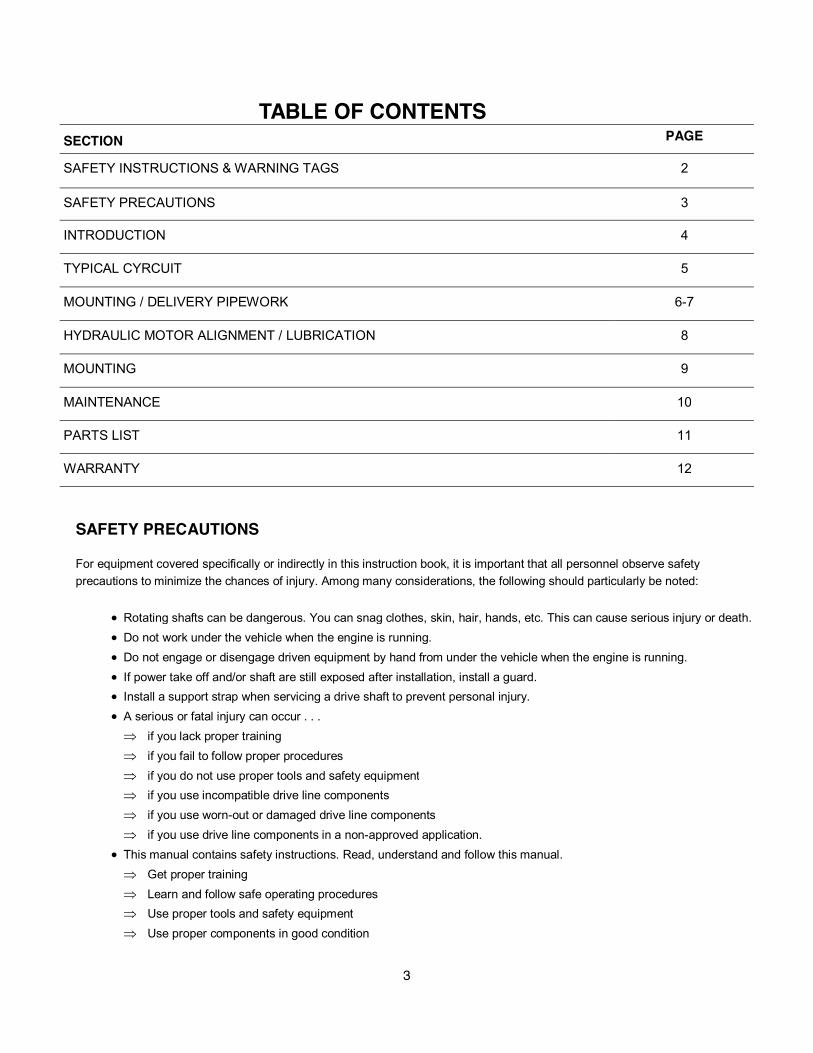
SAFETY PRECAUTIONS
For equipment covered specifically or indirectly in this instruction book, it is important that all personnel observe safetyprecautions to minimize the chances of injury. Among many considerations, the following should particularly be noted:
x Rotating shafts can be dangerous. You can snag clothes, skin, hair, hands, etc. This can cause serious injury or death.x Do not work under the vehicle when the engine is running.x Do not engage or disengage driven equipment by hand from under the vehicle when the engine is running.x If power take off and/or shaft are still exposed after installation, install a guard.x Install a support strap when servicing a drive shaft to prevent personal injury.x A serious or fatal injury can occur . . .�� if you lack proper training�� if you fail to follow proper procedures�� if you do not use proper tools and safety equipment�� if you use incompatible drive line components�� if you use worn-out or damaged drive line components�� if you use drive line components in a non-approved application.
x This manual contains safety instructions. Read, understand and follow this manual.�� Get proper training�� Learn and follow safe operating procedures�� Use proper tools and safety equipment�� Use proper components in good condition
TABLE OF CONTENTSSECTION PAGE
SAFETY INSTRUCTIONS &WARNING TAGS 2
SAFETY PRECAUTIONS 3
INTRODUCTION 4
HYDRAULIC MOTOR ALIGNMENT / LUBRICATION 8
MOUNTING 9
WARRANTY 12
TYPICAL CYRCUIT 5
MOUNTING / DELIVERY PIPEWORK 6-7
MAINTENANCE 10
PARTS LIST 11

4
INTRODUCTION
CONGRATULATIONS on your new purchase. Please examine the unit for shipping damage, and ifany damage is found, report it immediately to the carrier. If unit is to be installed at a later datemake sure it is stored in a clean, dry location.
Warning: Serious injury can result from operating or repairing the unit without reading theservice manual and taking adequate safety precautions.
Specifications
Performance Table
Max PSI Min RPM Max RPM WeightP40 36 500 1500 80 lbs
25 PSI 36 PSI
Speed CFM HPPotentialLiquid Flow(GPM)
CFM HPPotentialLiquid Flow(GPM)
500 rpm 12 1.5 38 11 1.6 25
800 rpm 19 2.7 61 18 2.8 40
1000 rpm 24 3.5 79 22 3.6 50
1200 rpm 30 4.3 95 27 4.4 59
1500 rpm 39 5.4 125 32 5.2 75
5
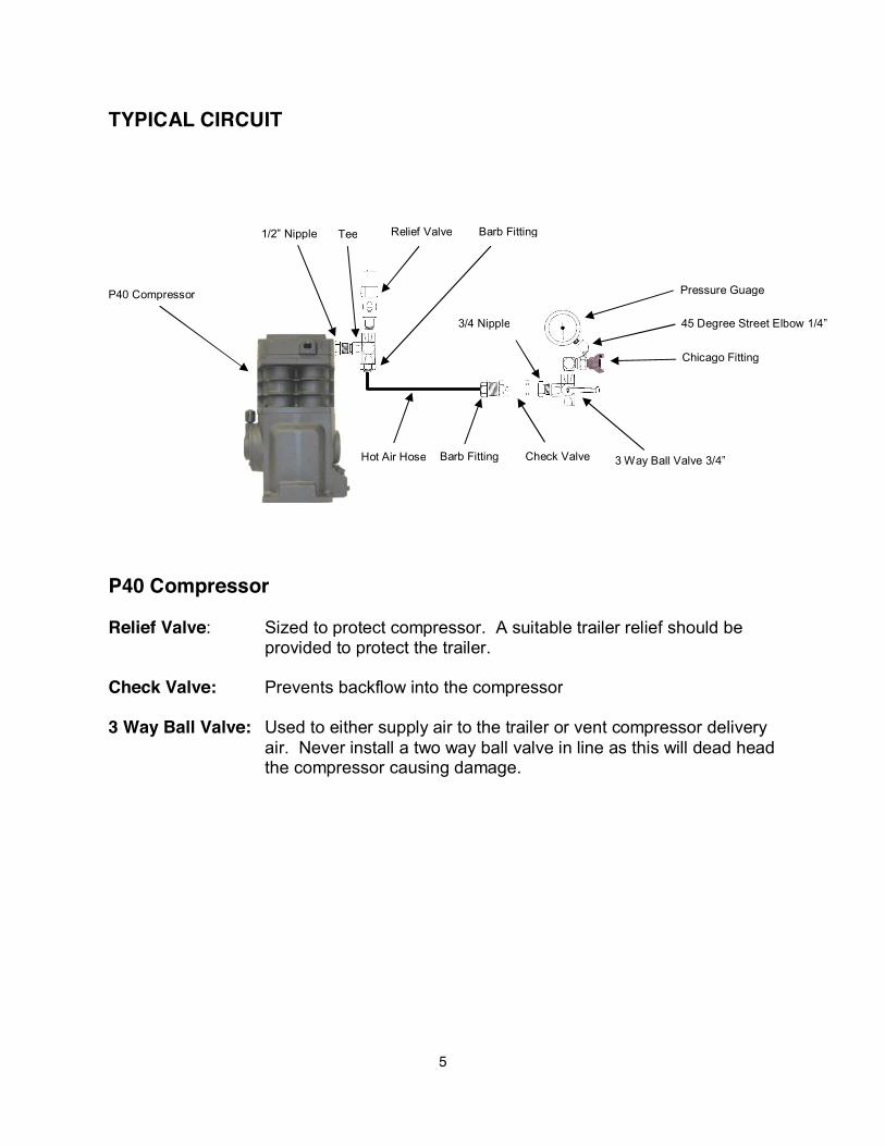
TYPICAL CIRCUIT
P40 Compressor
Relief Valve: Sized to protect compressor. A suitable trailer relief should beprovided to protect the trailer.
Check Valve: Prevents backflow into the compressor
3 Way Ball Valve: Used to either supply air to the trailer or vent compressor deliveryair. Never install a two way ball valve in line as this will dead headthe compressor causing damage.
1/2” Nipple
Hot Air Hose
Tee Relief Valve Barb Fitting
Check ValveBarb Fitting
3/4 Nipple
P40 Compressor
3 Way Ball Valve 3/4”
Pressure Guage
45 Degree Street Elbow 1/4”
Chicago Fitting

6
Air Filter
3/4” Street Elbow
Compressor
Drive Flange(1300 Series or 1100 Series)
Retaining BoltLeft Hand thread
torque to21-23 Ft/LBS
Universal PTOMounting Bracket
Relief Valve
1/2” x 3/4” NPT Tee
1/2” Close Nipple
Hose Clamp
Hot Air Hose 3/4”
Universal PTOMounting Bracket
Hot Air Hose 3/4”
Air Filter
3/4” Street Elbow
Retaining BoltLeft Hand thread
torque to21-23 Ft/LBS
4” long nipple3/4” Coupler
Relief Valve
1/2” x 3/4” NPT Tee
1/2” close nipple Hose Clamp
Hose Barb 3/4”
Hose Barb 3/4”
Mounting Configuration - Drivers Side - PTO Drive
Mounting Configuration Passenger Side - PTO Drive
Tilt upwards to allowwater to drain
Drive Flange(1300 Series or 1100 Series)
7
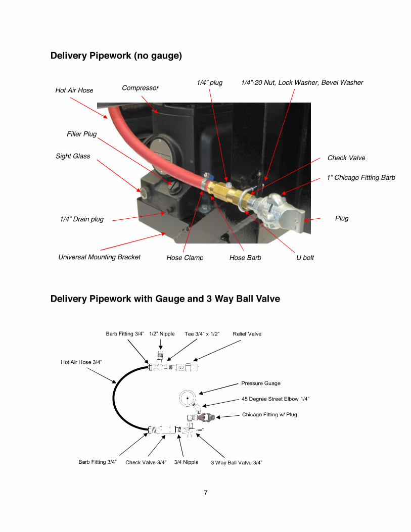
Hot Air Hose Compressor
Sight Glass
1/4” Drain plug
Universal Mounting Bracket Hose Clamp
Filler Plug
Hose Barb
Check Valve
U bolt
1/4”-20 Nut, Lock Washer, Bevel Washer
1” Chicago Fitting Barb
Plug
Delivery Pipework (no gauge)
1/4” plug
1/2” Nipple
3 Way Ball Valve 3/4”
Hot Air Hose 3/4”
Tee 3/4” x 1/2” Relief ValveBarb Fitting 3/4”
Check Valve 3/4”Barb Fitting 3/4”
Pressure Guage
45 Degree Street Elbow 1/4”
Chicago Fitting w/ Plug
Delivery Pipework with Gauge and 3 Way Ball Valve
3/4 Nipple
8
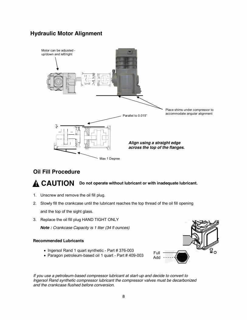
Oil Fill Procedure
! CAUTION1. Unscrew and remove the oil fill plug.
2. Slowly fill the crankcase until the lubricant reaches the top thread of the oil fill opening
and the top of the sight glass.
3. Replace the oil fill plug HAND TIGHT ONLY
Note : Crankcase Capacity is 1 liter (34 fl ounces)
Do not operate without lubricant or with inadequate lubricant.
FullAdd
Hydraulic Motor Alignment
Parallel to 0.015”
Max 1 Degree
Place shims under compressor toaccommodate angular alignment
Motor can be adjusted -up/down and left/right
Align using a straight edgeacross the top of the flanges.
Recommended Lubricants
x Ingersol Rand 1 quart synthetic - Part # 376-003x Paragon petroleum-based oil 1 quart - Part # 409-003
If you use a petroleum-based compressor lubricant at start-up and decide to convert toIngersol Rand synthetic compressor lubricant the compressor valves must be decarbonizedand the crankcase flushed before conversion.

9
Mounting
x The Maximum compound driveline angleis 11 degrees.
x The compressor driveshaft and the PTOdriveshaft should be parallel within 2degrees (A)
x The drive shaft should have a “U” bolthanger installed for safety.
To ensure correct mounting follow the recommendations below :
Power Take Off
x Horsepower and torque should be adequate for compressor rpm and pressurex Select a ratio that will provide desired compressor speed and engine rpmx Choose either 6 or 8-bolt side of transmission to provide adequate space for installation.
Constant Engine Speed
x To protect compressor against over speed and to provide an efficient offload the selectedengine speed must remain constant through the compressor discharge cycle.
Relief Valve
x If not using the Paragon mounting kit, size the relief valve for correct CFM and pressure.x Install at the compressor prior to the check valve.
Check Valve
x Must be suitable for reciprocating compressors and sized for maximum CFM of machine(see chart).
x The Paragon check valve has a 1/4” port that can be used for a pressure gauge. Ensure theplug is tight if not using a pressure guage.
Driveshaft
x The P40 is supplied with a 1310 series or 1100 series drive flange.x The compressor drive flange should be tapped lightly onto the shaft and then secured using thebolt supplied.
x The drive flange securing bolt is a LEFT HAND THREAD and should be torqued to 21-23 ft/lbs.
10
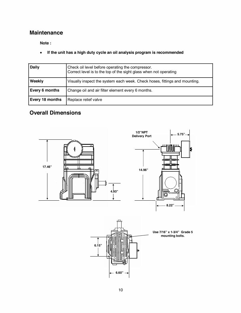
4.93”
17.46”
Overall Dimensions
Daily Check oil level before operating the compressor.Correct level is to the top of the sight glass when not operating
Weekly Visually inspect the system each week. Check hoses, fittings and mounting.
Every 6 months Change oil and air filter element every 6 months.
Every 18 months Replace relief valve
8.22”
5.75”
14.96”
1/2”NPTDelivery Port
6.15”
6.60”
Use 7/16” x 1-3/4” Grade 5mounting bolts.
MaintenanceNote :
x� If the unit has a high duty cycle an oil analysis program is recommended

11
Parts List.Item Part Number Description Qty
1 600-000 P40 Compressor 1
2 625-004 Air Filer (Complete) 1
3 575-001 Air Filter Element 1
4 376-003 Ingersoll Rand Synthetic lubricant (quart) 1
5 587-006 Hose - Hot Air 3/4" (per foot) ft
7 299-009 U Bolt 1/4” 1
8 92354-0253 1/4” lock washers 2
9 293-000 1/4” Bevel washers 2
10 85228 1/4” Nut 2
11 327-004 Hyd Hose Barb 1/2” Straight -8 x -8 NPTM - Brass 2
13 612-014 Check Valve 3/4" NPT 1
14 534-000 Chicago fitting 1/2" MNPT (no gauge port) 1
16 534-002 Dust plug 1
17 532-000 Tee - 1/2" x 1/2” x 1/2” 1
19 535-020 Close nipple 1/2” 1
20 535-021 Nipple 3/4” x 4” long (passenger mount) 1
21 530-005 Coupler 3/4” 1
22 533-026 Elbow - 3/4" street galvanized pipe 2
23 610-007 Relief Valve 1
24 85237 Clamp, Hose 1/2'' Heavy Duty 2
25 508-002 Mounting Bracket - PTO Drive 1
26 228-062 Setscrew 7/16” x 1-3/4” 4
27 294-012 Lock washer 7/16” 4
28 284-007 Nylock Nut 7/16” 4
29 562-022 Hydraulic Coupler, L110 Taper - Compressor end 1
30 562-024 Hydraulic Coupler Spider L110 Buna 1
31 562-021 Hydraulic Coupler Flange L110 7/8" w/ 1/4"key 1
32 535-004 Nipple - 3/4" NPT close black pipe 1
6 587-004 Hose - Hot Air 1/2" (per foot) ft
12 328-003 Hyd Hose Barb 3/4” 90 degree elbow -12 x -12 NPTM 1
15 534-001 Chicago Fitting 3/4" MNPT (gauge port) 1
18 532-002 Tee - 1/2" x 1/2" x 3/4" 1
33 825-400 Elbow 1/4" fnpt x 1/4" mnpt 45 deg - street 1
35 85233 Clamp, Hose 3/4” Heavy Duty 1
34 816-004 Ball Valve - 3/4" FNPT Brass 3 way 1
36 508-033 Hydraulic Mounting Bracket (90 deg) 1
5 409-003 Paragon Petroleum Based Oil (quart) 1

12
WARRANTY – P40 Compressor
Subject to the terms and conditions hereinafter set forth and set forth in General Terms of Sale, Paragon Tank Truck EquipmentLLC (the seller) warrants products and parts of its manufacture, when shipped, will be of good quality and will be free fromdefects in material and workmanship. This warranty applies only to Seller's equipment, under use and service in accordance withseller's written instructions, recommendations and ratings for installation, operating, maintenance and service of products, for aperiod as stated in the table below.
THIS WARRANTY EXTENDS ONLY TO BUYER AND/OR ORIGINAL END USER, AND IN NO EVENT SHALL THE SELLERBE LIABLE FOR PROPERTY DAMAGE SUSTAINED BY A PERSON DESIGNATED BY THE LAW OF ANY JURISDICTIONAS A THIRD PARTY BENEFICIARY OF THIS WARRANTY OR ANY OTHER WARRANTY HELD TO SURVIVE SELLER'SDISCLAIMER.
All accessories furnished by Seller but manufactured by others bear only that manufacturer's standard warranty.
All claims for defective products, parts, or work under this warranty must be made in writing immediately upon discovery and, inany event within one (1) year from date of shipment of the applicable item and all claims for defective work must be made inwriting immediately upon discovery and in any event within one (1) year from date of completion thereof by Seller. Unless donewith prior written consent of Seller, any repairs, alterations or disassembly of Seller's equipment shall void warranty. Installationand transportation costs are not included and defective items must be held for Seller's inspection and returned to Seller's Ex-works point upon request.
THERE ARE NO WARRANTIES, EXPRESSED, IMPLIED OR STATUTORY WHICH EXTEND BEYOND THE DESCRIPTIONON THE FACE HEREOF, INCLUDING WITHOUT LIMITATION, THE IMPLIED WARRANTIES OF MERCHANTABILITY ANDFITNESS OF PURPOSE.
After Buyer's submission of a claim as provided above and its approval, Seller shall at its option either repair or replace itsproduct, part, or work at the original Ex-works point of shipment, or refund an equitable portion of the purchase price.
The products and parts sold hereunder are not warranted for operation with erosive or corrosive material or those which may leadto build up of material within the product supplied, nor those which are incompatible with the materials of construction. The Buyershall have no claim whatsoever and no product or part shall be deemed to be defective by reason of failure to resist erosive orcorrosive action nor for problems resulting from build-up of material within the unit nor for problems due to incompatibility with thematerials of construction.
Any improper use, operation beyond capacity, substitution of parts not approved by Seller, or any alteration or repair by others insuch manner as in Seller's judgment affects the product materially and adversely shall void this warranty.
No employee or representative of Seller other than an Officer of the Company is authorized to change this warranty in any way orgrant any other warranty. Any such change by an Officer of the Company must be in writing.
The foregoing is Seller's only obligation and Buyer's only remedy for breach of warranty, and except for gross negligence, willfulmisconduct and remedies permitted under the General Terms of Sale. In no event shall Buyer be entitled to incidental orconsequential damages. Any action for breach of this agreement must commence within one (1) year after the cause of actionhas occurred.
October 2008
Product Type Warranty DurationNew 18 months from date of shipment, or 12 months after initial startup date, whichever occurs first
Paragon Tank Truck Equipment2111 US Hwy 411 NE, PO Box 200277, Cartersville, Georgia USA 30120
Tel 770.387.3820, 800.471.8769, Fax 770.387.3824www.hydraflow.biz

13