packard bell easynote sj series - tim.id.autim.id.au/laptops/packardbell/easynote sj.pdf · packard...
TRANSCRIPT
Packard BellEasyNote SJ
Disassembly Manual
11111
Packard Bell EasyNote SJ Disassembly Manual
1
Table of ContentsOverview............................................................................................................................................... 2Technician Notes ................................................................................................................................. 2Disassembly ......................................................................................................................................... 2Reassembly.......................................................................................................................................... 2Required Tools ..................................................................................................................................... 2Hazardous Voltage .............................................................................................................................. 3Avoid Electrostatic Discharge ............................................................................................................. 3Power Supply Unit ............................................................................................................................... 3Battery................................................................................................................................................... 4Hard Disk Drive .................................................................................................................................... 4Memory ................................................................................................................................................. 6Wireless LAN Adapter ......................................................................................................................... 7CPU and CPU Fan............................................................................................................................... 7Keyboard............................................................................................................................................... 9Optical Disk Drive...............................................................................................................................10Button Board.......................................................................................................................................11Top Cover ...........................................................................................................................................12HDD Board .........................................................................................................................................14ODD Board.........................................................................................................................................15Speakers.............................................................................................................................................16Subwoofer...........................................................................................................................................16Touchpad Button Board.....................................................................................................................17Standby Switch...................................................................................................................................17Modem Board.....................................................................................................................................18RJ11 Connector .................................................................................................................................18Bluetooth Module ...............................................................................................................................19Bluetooth Antenna .............................................................................................................................20Main Board .........................................................................................................................................21LCD Panel Assembly.........................................................................................................................22LCD Bezel...........................................................................................................................................23LCD Panel ..........................................................................................................................................24Inverter Board.....................................................................................................................................25Webcam..............................................................................................................................................25WLAN Antenna...................................................................................................................................26Notice..................................................................................................................................................27

Packard Bell EasyNote SJ Disassembly Manual
2
OverviewThis document contains step-by-step disassembly instructions for the Packard Bell EasyNoteSJ. The instructions are illustrated where necessary with images of the part that is beingremoved or disassembled.
Packard Bell reserves the right to make changes to the EasyNote SJ without notice.
Technician NotesOnly technicians authorized by Packard Bell B.V. should attempt to repair this equipment. Alltroubleshooting and repair procedures are detailed to allow only subassembly/module levelrepair. Because of the complexity of the individual boards and subassemblies, no one shouldattempt to make repairs at the component level or to make modifications to any printed wiringboard. Improper repairs can create a safety hazard. Any indication of component replacementor printed wiring board modifications may void any warranty or exchange allowances.
DisassemblyWhen disassembling the system unit, follow these general rules:
Turn off the power using the power button.Disconnect the adapter.Remove any SD/MMC card, ExpressCard or dummy card from the device.Do not disassemble the system into parts that are smaller than those specified in theinstructions.Label all removed connectors; note where the connector goes and in what position itwas installed.
ReassemblyReassembly is the reverse of the disassembly process. Use care to ensure that all cables andscrews are returned to their proper positions. Check that no tools or any loose parts have beenleft inside the casing. Check that everything is properly installed and tightened.
Required ToolsAll disassembly procedures can be performed using the following tools:
Small Phillips and flat-blade screwdriver.Hex-bolt #5 screwdriver

Packard Bell EasyNote SJ Disassembly Manual
3
Hazardous VoltageThere is hazardous voltage present inside thenotebook when it is connected to an AC supply,even when the notebook’s power switch is off.Exposure to hazardous voltage could causepersonal injury. To avoid risk of injury, contactan Authorized Service Provider for proper(un)installation of optional hardware devices.
Avoid Electrostatic DischargeElectrostatic electricity can easily damagecircuit cards and integrated circuits (ICs). Toreduce risk of damage, store them in protectivepackaging whenever they are not installed inthe system.
Add-in cards can be extremely sensitive to ESDand always require careful handling. Afterremoving the card from the notebook, place thecard flat on a grounded, static-free surface,component-side up. Use a conductive foam padif available, but not the card wrapper. Do notslide the card over any surface.
Before you install or remove memory modules,video memory, disk drives, circuit cards or otherdevices, protect them from static electricity. Todo so, make sure the notebook’s power switchis OFF. Then, unplug the notebook’s AC powercord. Before picking up the device you(un)install, you should wear an anti-static wristwrap (available at electronic supply stores). Besure to connect the wrist wrap to an unpaintedmetal portion of the notebook casing. As analternative, you can dissipate electrostatic build-up by touching an unpainted metal portion ofthe notebook casing with one hand. Then touchthe device you are (un)installing with the otherhand, and maintain continuous contact with ituntil it is (un)installed in the notebook.
Power Supply UnitUnder no circumstances should you attempt todisassemble the power supply. The powersupply contains no user-serviceable parts.Inside the power supply are hazardous voltagesthat can cause serious personal injury. Alwaysreturn a defective power supply to the dealer.
WARNINGEnsure that the notebook is disconnectedfrom its power source and from alltelecommunications links, networks, ormodem lines whenever the casing coveris removed. Do not operate the notebookwith the cover removed.
AVERTISSEMENTAssurez-vous que le système estdébranché de son alimentation ainsi quede toutes les liaisons detélécommunication, des réseaux, et deslignes de modem avant d’enlever lecapot. Ne pas utiliser le système quand lecapot est enlevé.
WARNUNGDas System darf weder an eineStromquelle angeschlossen sein nocheine Verbindung mit einerTelekommunikationseinrichtung, einemNetzwerk oder einer Modem-Leitunghaben, wenn die Gehäuseabdeckungentfernt wird. Nehmen Sie das Systemnicht ohne die Abdeckung in Betrieb.
ADVERTENCIAAsegúrese de que cada vez que se quitela cubierta del portátil, el sistema hayasido desconectado de la red dealimentación y de todos lo enlaces detelecomunicaciones, de red y de líneas demódem. No ponga en funcionamiento elsistema mientras la cubierta esté quitada.
WAARSCHUWINGZorg er voor dat alle verbindingen van ennaar de notebook (stroom, modem,netwerk, etc) verbroken worden voordatde behuizing geopend wordt. Zet denotebook nooit aan als de behuizinggeopend is.
AVVERTENZAPrima di rimuovere il coperchio del telaio,assicurarsi che il sistema sia scollegatodall’alimentazione, da tutti i collegamentidi comunicazione, reti o linee di modem.Non avviare il sistema senza aver primamesso a posto il coperchio.

44444
Packard Bell EasyNote SJ Disassembly Manual
4
BatteryPerform the following steps to remove the battery:
1. Make sure the power is off.2. Turn the notebook upside down.
Note: Use an anti-static mat or something soft like a piece of cloth underneath the notebook to prevent damageto the exterior of the notebook.
3. Push the 2 locks outwards to the release the battery.4. Slide the battery out of the compartment.
Fig. 1 Removing the battery.
Hard Disk DriveTo remove the hard disk drive, first remove the battery (see Battery) and then perform thefollowing steps:
1. Remove the 2 screws on the hard disk drive cover and remove the cover.
Fig. 2 Removing hard disk drive cover.
2. Pull the hard disk drive towards you to disconnect the drive.

55555
Packard Bell EasyNote SJ Disassembly Manual
5
Fig. 3 Disconnecting and removing hard disk drive(s).
3. Take the drive out of its compartment as shown in Fig. 3.4. Remove the 2 screws on the metal bracket to separate it from the hard disk drive.
Fig. 4 Location of hard disk drive bracket screws.
Note: The EasyNote SJ uses S-ATA hard drives exclusively. S-ATA hard drives have no jumpers and need nospecific configuration settings to work in a system with multiple hard drives.
Note: The hard drive bays are numbered in the casing (HDD1 and HDD2). The number of the bay correspondswith the sequence in the BIOS: the hard disk drive in bay 1 should be labelled HDD1 in the system BIOS.
66666
Packard Bell EasyNote SJ Disassembly Manual
6
Note: If the system ships with 2 hard drives, they will be configured as 2 separate drives and not in any type ofRAID configuration.
MemoryTo remove the memory installed, first remove the battery (see Battery) and then perform thefollowing steps:
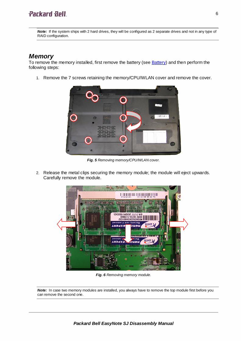
1. Remove the 7 screws retaining the memory/CPU/WLAN cover and remove the cover.
Fig. 5 Removing memory/CPU/WLAN cover.
2. Release the metal clips securing the memory module; the module will eject upwards.Carefully remove the module.
Fig. 6 Removing memory module.
Note: In case two memory modules are installed, you always have to remove the top module first before youcan remove the second one.

77777
Packard Bell EasyNote SJ Disassembly Manual
7
Wireless LAN AdapterTo remove the wireless LAN adapter, first remove the battery (see Battery) and then performthe following steps:
1. Remove the 7 screws retaining the memory/CPU/WLAN cover (see Fig. 5).2. Carefully disconnect the 2 wireless antenna cables. Take note of which coloured wire is
connected to which connector on the adapter.
Fig. 7 Location of antenna cable connectors and screws.
3. Remove the 2 screws securing the wireless LAN adapter (see Fig. 7); the adapter willeject upwards.
4. Take out the wireless LAN adapter from the slot.
CPU and CPU FanTo remove the CPU, first remove the battery (see Battery) and then perform the following steps:
1. Remove the 7 screws retaining the memory/CPU/WLAN cover (see Fig. 5).2. Remove the 3 screws holding the CPU fan.
88888
Packard Bell EasyNote SJ Disassembly Manual
8
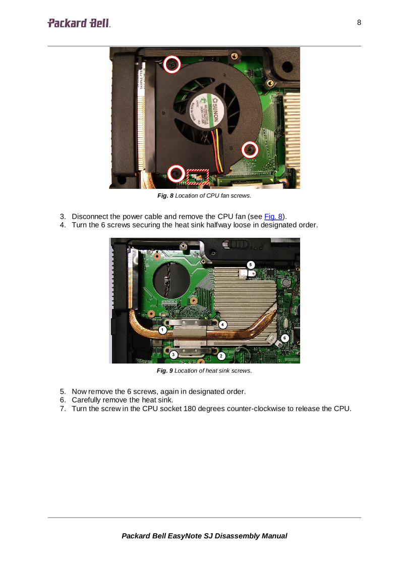
Fig. 8 Location of CPU fan screws.
3. Disconnect the power cable and remove the CPU fan (see Fig. 8).4. Turn the 6 screws securing the heat sink halfway loose in designated order.
Fig. 9 Location of heat sink screws.
5. Now remove the 6 screws, again in designated order.6. Carefully remove the heat sink.7. Turn the screw in the CPU socket 180 degrees counter-clockwise to release the CPU.
99999
Packard Bell EasyNote SJ Disassembly Manual
9
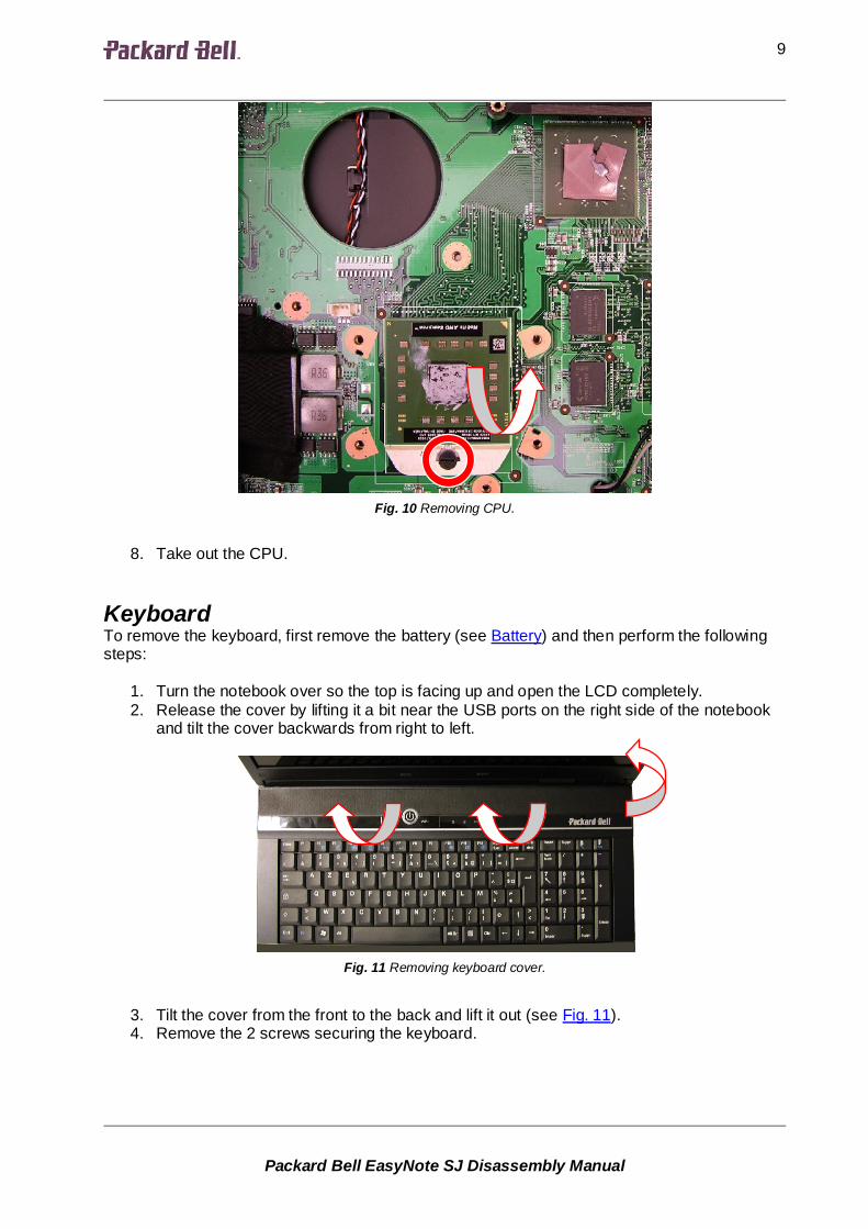
Fig. 10 Removing CPU.
8. Take out the CPU.
KeyboardTo remove the keyboard, first remove the battery (see Battery) and then perform the followingsteps:
1. Turn the notebook over so the top is facing up and open the LCD completely.2. Release the cover by lifting it a bit near the USB ports on the right side of the notebook
and tilt the cover backwards from right to left.
Fig. 11 Removing keyboard cover.
3. Tilt the cover from the front to the back and lift it out (see Fig. 11).4. Remove the 2 screws securing the keyboard.
1010101010
Packard Bell EasyNote SJ Disassembly Manual
10
Fig. 12 Location of keyboard screws.
5. Tilt the keyboard gently forward (see Fig. 12).6. Before removing the keyboard entirely, carefully release the clip securing the flat cable
and disconnect the cable from the main board.
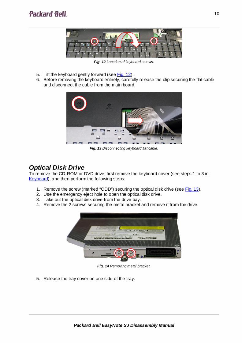
Fig. 13 Disconnecting keyboard flat cable.
Optical Disk DriveTo remove the CD-ROM or DVD drive, first remove the keyboard cover (see steps 1 to 3 inKeyboard), and then perform the following steps:
1. Remove the screw (marked “ODD”) securing the optical disk drive (see Fig. 13).2. Use the emergency eject hole to open the optical disk drive.3. Take out the optical disk drive from the drive bay.4. Remove the 2 screws securing the metal bracket and remove it from the drive.
Fig. 14 Removing metal bracket.
5. Release the tray cover on one side of the tray.

1111111111
Packard Bell EasyNote SJ Disassembly Manual
11
Fig. 15 Releasing tray cover (side).
6. Next release the tray cover on the bottom of the drive.
Fig. 16 Releasing tray cover (bottom).
7. Remove the cover and close the tray!
Button BoardThe button board contains the power button, the ECO and WiFi button, and the status LEDs. Toremove the button board, remove the keyboard cover (see steps 1 to 3 in Keyboard), and thenperform the following steps:
1. Remove the 2 screws securing the button board

1212121212
Packard Bell EasyNote SJ Disassembly Manual
12
Fig. 17 Location button board screws.
2. Carefully disconnect the flat cable from the main board (see Fig. 17).3. Lift out the button board.4. Disconnect the flat cable from the button board.
Fig. 18 Disconnecting flat cable.
Top CoverTo remove the top cover, remove the hard disks (see Hard Disk Drive), remove the optical diskdrive (see Optical Disk Drive), remove the LCD panel assembly (see LCD Panel Assembly), andthen perform the following steps:
1. Carefully disconnect the speaker cables connector near the palm rest at the right.

1313131313
Packard Bell EasyNote SJ Disassembly Manual
13
Fig. 19 Location of speaker cables connector.
2. Disconnect the standby-switch cable.
Fig. 20 Disconnecting standby-switch cable.
3. Disconnect the touchpad cable.
Fig. 21 Disconnecting touchpad cable.

1414141414
Packard Bell EasyNote SJ Disassembly Manual
14
4. Disconnect the button board flat cable (see Fig. 17).5. Remove the 7 screws securing the cover.
Fig. 22 Location of top cover screws.
6. Turn the notebook upside down.7. Remove the 13 screws (all M2.5x6).
Fig. 23 Location of top cover screws underside.
8. Turn the notebook upside down and remove the top cover.
HDD BoardThe HDD board contains the two Serial ATA connectors. To remove the HDD board, firstremove the top cover (see Top Cover), and then perform the following steps:

1515151515
Packard Bell EasyNote SJ Disassembly Manual
15
1. Remove the 2 screws securing the HDD board.
Fig. 24 Location of HDD board screws.
2. Lift out the HDD board (it has been clicked onto the main board).
ODD BoardThe ODD board extends the IDE connector for the optical drive from the main board. To removethe ODD board, first remove the top cover (see Top Cover), and then perform the followingsteps:
1. Remove the screw securing the ODD board.
Fig. 25 Location of ODD board screw.
2. Take the ODD board aside and disconnect it from the main board.3. Remove the ODD board.

1616161616
Packard Bell EasyNote SJ Disassembly Manual
16
SpeakersTo remove the speakers, first remove the top cover (see Top Cover), and then perform thefollowing steps:
1. Remove the screws securing each speaker.
Fig. 26 Location of speaker screws.
2. Release the speaker cables from the clips and remove any tape holding the cables.
Note: The speakers can only be exchanged as a pair.
SubwooferTo remove the subwoofer, first remove the top cover (see Top Cover), and then perform thefollowing steps:
1. Disconnect the subwoofer cable from the main board (see Fig. 27-A).
Fig. 27 Location of subwoofer and cable.
A
B

1717171717
Packard Bell EasyNote SJ Disassembly Manual
17
2. Remove the 2 screws securing the subwoofer and lift it out (see Fig. 27-B).
Note: The subwoofer is optional.
Touchpad Button BoardThe touchpad button board is located on the top cover. To remove it, first remove the top cover(see Top Cover), and then perform the following steps:
1. Release the clip securing the flat cable (the clip folds up) and disconnect the flat cablefrom the touchpad.
Fig. 28 Removing touchpad button board and cable.
2. Remove the 2 screws securing the touchpad button board and lift out the boardincluding the cable (see Fig. 28).
Note: The touchpad is part of the top cover and it cannot be exchanged separately. You cannot remove the flatcable from the touchpad button board.
Standby SwitchThe standby switch works as a soft power switch when the lid is closed; it is located in the topcover. To remove the standby switch, first remove the top cover (see Top Cover), and thenperform the following steps:
1. Remove the screw securing the standby switch.

1818181818
Packard Bell EasyNote SJ Disassembly Manual
18
Fig. 29 Location of standby switch screw.
2. Clear the cable and remove the standby switch.
Modem BoardTo remove the modem board, first remove the top cover (see Top Cover), and then perform thefollowing steps:
1. Remove the 2 screws securing the modem (see Fig. 30-A).
Fig. 30 Location of standby switch screw.
2. Take out the modem; it has been clicked onto the main board.3. Disconnect the cable from the modem.
RJ11 ConnectorTo remove the RJ11 connector, first remove the top cover (see Top Cover), and then performthe following steps:
B
A

1919191919
Packard Bell EasyNote SJ Disassembly Manual
19
1. Disconnect the modem cable from the main board (see Fig. 30-B).2. Remove the screw securing the RJ11 connector bracket.
Fig. 31 Location of RJ11 connector bracket screw.
3. Take out the RJ11 connector and cable.
Fig. 32 Removing RJ11 connector.
Note: You may need to remove the HDD board (see HDD Board) and/or the ODD board (see ODD Board) toget enough clearance for the cable.
Bluetooth ModuleTo remove the Bluetooth module, first remove the top cover (see Top Cover), and then performthe following steps:
1. Disconnect the antenna and the cable from the Bluetooth module.

2020202020
Packard Bell EasyNote SJ Disassembly Manual
20
Fig. 33 Disconnect Bluetooth antenna and cable.
2. Remove the screw securing the Bluetooth module.
Fig. 34 Location of Bluetooth module screw.
3. Remove the Bluetooth module.
Note: Bluetooth is optional.
Bluetooth AntennaTo remove the Bluetooth antenna, first remove the top cover (see Top Cover), and then performthe following steps:
1. Disconnect the antenna from the Bluetooth module (see Fig. 33).2. Remove the Bluetooth antenna; it has been glued onto place.

2121212121
Packard Bell EasyNote SJ Disassembly Manual
21
Fig. 35 Removing Bluetooth antenna.
Note: Bluetooth is optional.
Main BoardTo remove the main board, remove the CPU and the CPU fan (see CPU and CPU Fan), removethe memory (see Memory), remove the wireless LAN adapter (see Wireless LAN Adapter),remove the HDD and ODD boards (see HDD Board and ODD Board), remove the modemboard (see Modem Board), and then perform the following steps:
1. Remove the 7 screws (marked with an arrow) securing the main board.
Fig. 36 Location of main board screws.
2. Remove the 2 hex bolts adjacent to the DVI-I connector.3. Lift up the main board.4. Disconnect the Bluetooth cable (optional).5. Lift the main board out and turn it upside down.

2222222222
Packard Bell EasyNote SJ Disassembly Manual
22
6. Disconnect the RTC battery cable and remove the RTC battery; it has been glued ontoplace.
Fig. 37 Location of RTC battery.
LCD Panel AssemblyTo disassembly the LCD panel assembly, first remove the keyboard (see Keyboard), removethe CPU cover (see step 1 in CPU and CPU Fan), remove the wireless LAN antenna (see step2 in Wireless LAN Adapter), and then perform the following steps:
1. Remove the LCD cable cover.2. Disconnect the 3 LCD cable connectors.
Fig. 38 Disconnecting LCD cable connectors.
3. Pull the wireless LAN antenna cables through the base and clear them from the clips(see Fig. 38).
4. Remove 2 screws from the back panel of the notebook.

2323232323
Packard Bell EasyNote SJ Disassembly Manual
23
Fig. 39 Location of screws on back panel.
5. Remove 2 screws from the bottom of the notebook.
Fig. 40 Location of screws.
5. Open the LCD panel to a 90-degree angle and lift out the LCD panel assembly.
LCD BezelTo remove the LCD bezel, first remove the LCD panel assembly (see LCD Panel Assembly),and then do the following:
1. Remove the 4 rubber stoppers from the upper part and 2 stoppers from the lower part ofthe LCD bezel.
Fig. 41 Location of stoppers/screws securing LCD bezel.
2. Remove the 6 screws (that were covered by the stoppers) securing the LCD bezel.3. Remove the LCD bezel; it has been clicked into place.

2424242424
Packard Bell EasyNote SJ Disassembly Manual
24
LCD PanelTo remove the LCD panel, first remove the LCD bezel (see LCD Bezel), and then do thefollowing:
1. Remove the 4 screws from the hinges.
Fig. 42 Location of screws securing hinges.
2. Disconnect both cables from the inverter board.
Fig. 43 Disconnecting cables from inverter board.
3. Remove the screw securing the grounding cable.

2525252525
Packard Bell EasyNote SJ Disassembly Manual
25
Fig. 44 Removing grounding cable screw.
4. Lift out the panel.5. Remove the 4 screws on each side securing the brackets for the panel.
Fig. 45 Location of screw securing brackets.
6. Push the clips to disconnect the LCD cable from the back of the panel.
Inverter BoardTo remove the inverter board, first remove the LCD bezel (see LCD Bezel), and then do thefollowing:
1. Disconnect both cables from the inverter board (see Fig. 43).2. Remove the screw securing the inverter board and extract the board; it may be glued
onto place.
WebcamTo remove the webcam, first remove the LCD bezel (see LCD Bezel), and then do the following:
1. Disconnect the cable from the webcam.

2626262626
Packard Bell EasyNote SJ Disassembly Manual
26
Fig. 46 Location of webcam connector.
2. Lift out the webcam; it may be glued and/or taped onto place.
Note: You have to remove the LCD panel if the webcam cable needs to be replaced.
WLAN AntennaTo remove the wireless antenna, first remove the LCD panel (see LCD Panel), and then do thefollowing:
1. The wireless LAN antenna has been glued onto place, loosen both.
Fig. 47 Location WLAN antenna cables.
2. Remove the webcam (see Webcam) to clear the cable of the antenna on the left3. Release the cable from the clips in the shielding foil.

2727272727
Packard Bell EasyNote SJ Disassembly Manual
27
NoticeThe information in this guide is subject to change without notice.
This guide contains information protected by copyright. No part of this guide may bephotocopied or reproduced in any form or by any means without prior written consent fromPackard Bell B.V.
PACKARD BELL B.V. SHALL NOT BE HELD LIABLE FOR TECHNICAL OR EDITORIALERRORS OR OMISSIONS CONTAINED HEREIN; NOR FOR INCIDENTAL ORCONSEQUENTIAL DAMAGES RESULTING FROM THE FURNISHING, PERFORMANCE, ORUSE OF THIS MATERIAL.
Copyright © 2007 Packard Bell B.V. All rights reserved.
Packard Bell is a trademark of Packard Bell B.V.The names of actual companies and products mentioned herein may be trademarks and/orregistered trademarks of their respective owners.
The software described in this guide is furnished under a license agreement or nondisclosureagreement. The software may be used or copied only in accordance with the terms of theagreement.
EasyNote SJ Disassembly ManualAuthor: Wouter Willemse & Juan M. CalviñoFirst Edition: September 2007Version: 1.0Part Number: 7434820000
Packard Bell B.V.www.packardbell.com