packet switched networks wired – local, metropolitan, and wide area …€¦ · · 2017-11-30st...
TRANSCRIPT

Sup
erse
ded
by T
MU
TE
410
01 S
T v1
.0, 2
5/05
/201
7
Packet Switched Networks Wired – Local, Metropolitan, and Wide Area Networks
T HR TE 41001 ST
Standard
Version 2.0
Issued Date: 3 October 2014
Important Warning This document is one of a set of standards developed solely and specifically for use on the rail network owned or managed by the NSW Government and its agencies. It is not suitable for any other purpose. You must not use or adapt it or rely upon it in any way unless you are authorised in writing to do so by a relevant NSW Government agency. If this document forms part of a contract with, or is a condition of approval by, a NSW Government agency, use of the document is subject to the terms of the contract or approval. This document may not be current. Current standards are available for download from the Asset Standards Authority website at www.asa.transport.nsw.gov.au. © State of NSW through Transport for NSW
T HR TE 41001 ST
Sup
erse
ded
by T
MU
TE
410
01 S
T v1
.0, 2
5/05
/201
7
© State of NSW through Transport for NSW
Standard governance
Owner: Lead Telecommunications Engineer, Asset Standards Authority
Authoriser: Chief Engineer Rail, Asset Standards Authority
Approver: Director, Asset Standards Authority on behalf of ASA Configuration Control Board
Document history
Version Summary of change
1.0 First issue
2.0 Reformat to new document template, clarify accessibility text, reference derived content from T HR TE 81001 ST within section 7, reference derived content from T HR TE 81002 ST within section 8, reference T MU TE 81003 ST within section 9.2, and clarify section 9.10 to align with draft RISSB type approval standard AS 7659.
Packet Switched Networks Wired – Local, Metropolitan, and Wide Area Networks Version 2.0
Issued Date: 3 October 2014
For queries regarding this document, please email the ASA at
or visit www.asa.transport.nsw.gov.au

T HR TE 41001 ST Packet Switched Networks Wired – Local, Metropolitan, and Wide Area Networks
Version 2.0 Issued Date: 3 October 2014
© State of NSW through Transport for NSW Page 3 of 29
Preface
The Asset Standards Authority (ASA) is an independent unit within Transport for NSW (TfNSW)
and is the network design and standards authority for defined NSW transport assets.
The ASA is responsible for developing engineering governance frameworks to support industry
delivery in the assurance of design, safety, integrity, construction, and commissioning of
transport assets for the whole asset life cycle. In order to achieve this, the ASA effectively
discharges obligations as the authority for various technical, process, and planning matters
across the asset life cycle.
The ASA collaborates with industry using stakeholder engagement activities to assist in
achieving its mission. These activities help align the ASA to broader government expectations of
making it clearer, simpler, and more attractive to do business within the NSW transport industry,
allowing the supply chain to deliver safe, efficient, and competent transport services.
The ASA develops, maintains, controls, and publishes a suite of standards and other
documentation for transport assets of TfNSW. Further, the ASA ensures that these standards
are performance based to create opportunities for innovation and improve access to a broader
competitive supply chain.
This document has been developed by the Chief Engineer Rail section of the ASA, reviewed by
a committee of TfNSW cluster representatives, and approved by the ASA Configuration Control
Board.
This standard specifies the requirements for wired packet switching networks used for the
purpose of data exchange between connected ethernet and internet protocol (IP) enabled
computer systems, across local, metropolitan, and wide area networks.
Sup
erse
ded
by T
MU
TE
410
01 S
T v1
.0, 2
5/05
/201
7

T HR TE 41001 ST Packet Switched Networks Wired – Local, Metropolitan, and Wide Area Networks
Version 2.0 Issued Date: 3 October 2014
© State of NSW through Transport for NSW Page 4 of 29
Table of contents
1. ............................................................................................................................................5 Introduction
2. ...................................................................................................................................................5 Purpose2.1. ..................................................................................................................................................................... 5 Scope
2.2. ............................................................................................................................................................. 7 Application
3. ...........................................................................................................................7 Reference documents
4. ...........................................................................................................................9 Terms and definitions
5. .................................10 Functional requirements for data communication and terminal equipment5.1. ................................................................................................................................. 11 Bridging and management
5.2. ....................................................................... 11 Ethernet operations, administration, and maintenance (OAM)
5.3. ................................................................................................................................ 12 10 Mb/s ethernet interfaces
5.4. .............................................................................................................................. 12 100 Mb/s ethernet interfaces
5.5. .................................................................................................................................. 12 1 Gb/s ethernet interfaces
5.6. ................................................................................................................................ 13 10 Gb/s ethernet interfaces
5.7. ................................................................................................................................ 13 40 Gb/s ethernet interfaces
5.8. .............................................................................................................................. 14 100 Gb/s ethernet interfaces
5.9. ............................................................................................................................................ 14 Power over ethernet
5.10. ........................................................................................................................... 14 Modular transceiver packages
5.11. ................................................................................................................... 14 Port-based network access control
5.12. ................................................................................ 14 Internet protocol and internet control message protocol
5.13. .......................................................................................................................... 14 First hop redundancy protocol
5.14. .................................................................................................................................. 15 Exterior gateway protocol
5.15. ................................................................................................................................................ 15 Quality of service
6. .............................................................15 Network interfaces between DTE, LAN and WAN systems6.1. ............................................................................................................................ 16 DTE to LAN network interface
6.2. ........................................................................................................................... 17 LAN to LAN network interface
6.3. .......................................................................................................................... 17 LAN to WAN network interface
6.4. ......................................................................................................................... 17 WAN to WAN network interface
7. ...................................................................................................17 Interfaces to physical environment
8. ....................................................................................18 Interfaces to network management systems
9. ...............................................20 Non-functional requirements for wired packet switched networks9.1. ........................................................................................................................................................... 20 Availability
9.2. .................................................................................................................................................... 21 Interoperability
9.3. ..................................................................................................................................................... 22 Maintainability
9.4. ...................................................................................................................................................... 23 Manageability
9.5. ........................................................................................................................................................ 24 Performance
9.6. ............................................................................................................................................................. 24 Reliability
9.7. ..................................................................................................................................... 25 Work, health, and safety
9.8. ................................................................................................................................................................ 25 Security
9.9. ............................................................................................................................................................ 28 Scalability
9.10. ...................................................................................................................................................... 28 Supportability
9.11. ....................................................................................................................................................... 29 Sustainability
Sup
erse
ded
by T
MU
TE
410
01 S
T v1
.0, 2
5/05
/201
7
T HR TE 41001 ST Packet Switched Networks Wired – Local, Metropolitan, and Wide Area Networks
Version 2.0 Issued Date: 3 October 2014
© State of NSW through Transport for NSW Page 5 of 29
1. Introduction
Railway communication systems for applications within the signals and control systems,
telecommunications, electrical, and rolling stock disciplines are increasingly based on ethernet
and internet protocol (IP) enabled computer systems. Local, metropolitan, and wide area wired
networks shall align with national and international standards to create open industry
involvement, increased competition, and optimal asset stewardship outcomes.
2. Purpose
This document standardises wired packet switching networks used for the purpose of data
exchange between connected ethernet and internet protocol (IP) enabled computer systems,
across local, metropolitan, and wide area networks.
2.1. Scope
This document specifies the functional requirements for the following system interfaces:
• data terminal equipment to local area network (DTE to LAN systems)
• local area network to local area network (LAN to LAN systems)
• local area network to wide area network (LAN to WAN systems)
• wide area network to wide area network (WAN to WAN systems)
• LAN and WAN systems to physical environment
• LAN and WAN systems to network management systems
For simplicity and readability, this document considers a metropolitan area network to be a local
area network (LAN).
This document specifies wired packet switch networking functional requirements for data
communications equipment (DCE) and data terminal equipment (DTE).
The functional requirements specified in this document principally relate to the physical, data
link and network layers of the open systems interconnection (OSI) model defined in
ISO/IEC 7498-1 and the link and internet layers of the internet protocol suite (commonly referred
to as the TCP/IP model).
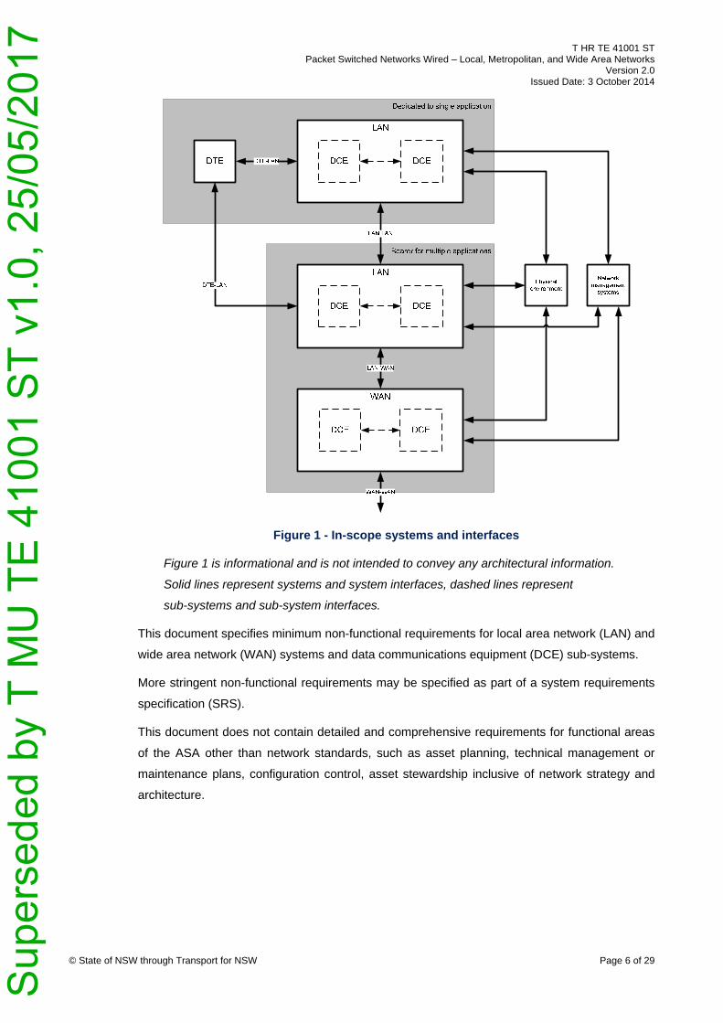
Figure 1 shows the systems and interfaces that are in scope.
Sup
erse
ded
by T
MU
TE
410
01 S
T v1
.0, 2
5/05
/201
7
T HR TE 41001 ST Packet Switched Networks Wired – Local, Metropolitan, and Wide Area Networks
Version 2.0 Issued Date: 3 October 2014
© State of NSW through Transport for NSW Page 6 of 29
Figure 1 - In-scope systems and interfaces
Figure 1 is informational and is not intended to convey any architectural information.
Solid lines represent systems and system interfaces, dashed lines represent
sub-systems and sub-system interfaces.
This document specifies minimum non-functional requirements for local area network (LAN) and
wide area network (WAN) systems and data communications equipment (DCE) sub-systems.
More stringent non-functional requirements may be specified as part of a system requirements
specification (SRS).
This document does not contain detailed and comprehensive requirements for functional areas
of the ASA other than network standards, such as asset planning, technical management or
maintenance plans, configuration control, asset stewardship inclusive of network strategy and
architecture.
Sup
erse
ded
by T
MU
TE
410
01 S
T v1
.0, 2
5/05
/201
7
T HR TE 41001 ST Packet Switched Networks Wired – Local, Metropolitan, and Wide Area Networks
Version 2.0 Issued Date: 3 October 2014
© State of NSW through Transport for NSW Page 7 of 29
In the special case where a wired packet switch network is required to comply with this standard
even though the DTE are not ethernet and internet protocol enabled, where the DTE to LAN
network interface is provided by a RS232 or RS422 serial interface, the following applies:
• the DTE system is out of scope
• the DTE to LAN system interface is out of scope
• all other sub-system and system interfaces are in scope
2.2. Application
A requirement applies to both LAN and WAN systems unless it is explicitly qualified as applying
to either LAN or WAN systems.
This standard applies to all uses of LAN and WAN systems.
This standard applies to installations of LAN and WAN systems. For example, within fixed
premises or on rolling stock.
This standard applies to LAN and WAN systems regardless of whether they are used to support
safety related functions. A requirement applies unless it is explicitly qualified as applying to
either safety or non-safety related functions.
In order to apply this standard for safety related communication, an EN 50159 assessment shall
be performed to categorise the transmission system and to ensure the consistency and
appropriateness of defences implemented by the safety related system.
3. Reference documents
International standards
EN 50159 Railway Applications - Communication, Signalling and Processing Systems - Safety-
related Communication in Transmission Systems
EN 60825-1 Safety of laser products - Equipment classification and requirements
EN 60825-2 Safety of laser products - Safety of optical fibre communication systems (OFCS)
EN 60950-1 Information technology equipment - Safety - General requirements
EN 61508-4 Functional safety of electrical/electronic/programmable electronic safety-related
systems - Part 4: Definitions and abbreviations
ISO/IEC 18028 Information technology - Security techniques - IT network security
PD IEC TR 62380 Reliability data handbook - Universal model for reliability prediction of
electronics components, PCBs and equipment
Sup
erse
ded
by T
MU
TE
410
01 S
T v1
.0, 2
5/05
/201
7
T HR TE 41001 ST Packet Switched Networks Wired – Local, Metropolitan, and Wide Area Networks
Version 2.0 Issued Date: 3 October 2014
© State of NSW through Transport for NSW Page 8 of 29
IEC 60050-191 International Electrotechnical Vocabulary. Chapter 191: Dependability and
quality of service
IEEE 802.1AB Station and Media Access Control Connectivity Discovery
IEEE 802.1D Media access control (MAC) Bridges
IEEE 802.1Q Virtual LANs
IEEE 802.1X Port-Based Network Access Control
IEEE 802.3 Ethernet
IETF RFC 1242 Benchmarking Terminology for Network Interconnection Devices
IETF RFC 2474 Definition of the Differentiated Services Field (DS Field) in the IPv4 and IPv6
Headers
IETF RFC 2544 Benchmarking Methodology for Network Interconnect Devices
IETF RFC 3768 Virtual Router Redundancy Protocol (VRRP)
IETF RFC 4271 A Border Gateway Protocol 4 (BGP-4)
IETF STD 5 Internet Protocol, Internet Control Message Protocol
ISO/IEC 27001 Information technology - Security techniques - Information security management
systems - Requirements
ISO/IEC 7498-1 Information technology – Open Systems Interconnection – Basic Reference
Model: The Basic Model
MIL-HDBK-217F Notice 2 Reliability Prediction of Electronic Equipment
Telcordia SR-332 Reliability Prediction Procedure for Electronic Equipment
Transport for NSW standards
T HR TE 21002 ST Communications Earthing and Surge Suppression
T HR TE 81001 ST Telecommunication Equipment – Physical Interfaces and Environmental
Conditions
T HR TE 81002 ST Telecommunication Equipment – Network Management
T MU TE 81003 ST Test Processes and Documentation for Programmable Electronic Systems
and Software
TS 10502 AEO Authorisation Requirements
TS 10506 AEO Guide to Verification and Validation
Sup
erse
ded
by T
MU
TE
410
01 S
T v1
.0, 2
5/05
/201
7
T HR TE 41001 ST Packet Switched Networks Wired – Local, Metropolitan, and Wide Area Networks
Version 2.0 Issued Date: 3 October 2014
© State of NSW through Transport for NSW Page 9 of 29
4. Terms and definitions
The following terms and definitions apply in this document:
BGP border gateway protocol
CFR constant failure rate
constant failure rate (as defined in IEC 60050-191) that period, if any, in the life of a
non-repaired item during which the failure rate is approximately constant
DCE data communication equipment
data communication equipment a physical network node. Example, a switch, router
DTE data terminal equipment
data terminal equipment computer system with one or more internet protocol addresses
assigned to its network interfaces for the purpose of resource sharing amongst systems
connected to the communication network. For example, workstation, printer, telephone
EN European norms
EOS end of sale
end of sale the date when the original equipment manufacturer (OEM) withdraws a product
from sale, both directly and through its authorised points of sale; for example, distributors and
resellers
field replaceable units part that can be removed and replaced without having to send the
system to a repair facility
first offered for sale the date when the OEM first offers a product for sale in the Australian
market
IEC International Electrotechnical Commission
IEEE Institute of Electrical and Electronics Engineers
IETF Internet Engineering Task Force
ICMP internet control message protocol
LAN local area network
local area network computer network consisting of switches which forward ethernet frames
LLDP link layer discovery protocol
MDI media dependent interface
MTTF mean time to failure
mean time to failure (as defined in IEC 60050-191) the expectation of the time to failure
Sup
erse
ded
by T
MU
TE
410
01 S
T v1
.0, 2
5/05
/201
7
T HR TE 41001 ST Packet Switched Networks Wired – Local, Metropolitan, and Wide Area Networks
Version 2.0 Issued Date: 3 October 2014
© State of NSW through Transport for NSW Page 10 of 29
OAM operations, administration, and maintenance
OEM original equipment manufacturer
operational [availability] (as defined in IEC 60050-191) qualifies a value determined under
given operational conditions
PNAC port-based network access control
RADIUS remote authentication dial in user service
safety related (as defined in EN 61508-4) designated system that both
– implements the required safety functions necessary to achieve or maintain a safe state for the
equipment under control; and
– is intended to achieve, on its own or with other electrical, electronic, or programmable
electronic safety-related systems and other risk reduction measures, the necessary safety
integrity for the required safety functions
steady state [availability] (as defined in IEC 60050-191) qualifies a value determined for
conditions of an item when characteristic parameters of the item remain constant
TACACS+ terminal access controller access-control system plus
VRRP virtual router redundancy protocol
WAN wide area network
wide area network computer network consisting of routers, which forward internet protocol (IP)
packets
5. Functional requirements for data communication and terminal equipment
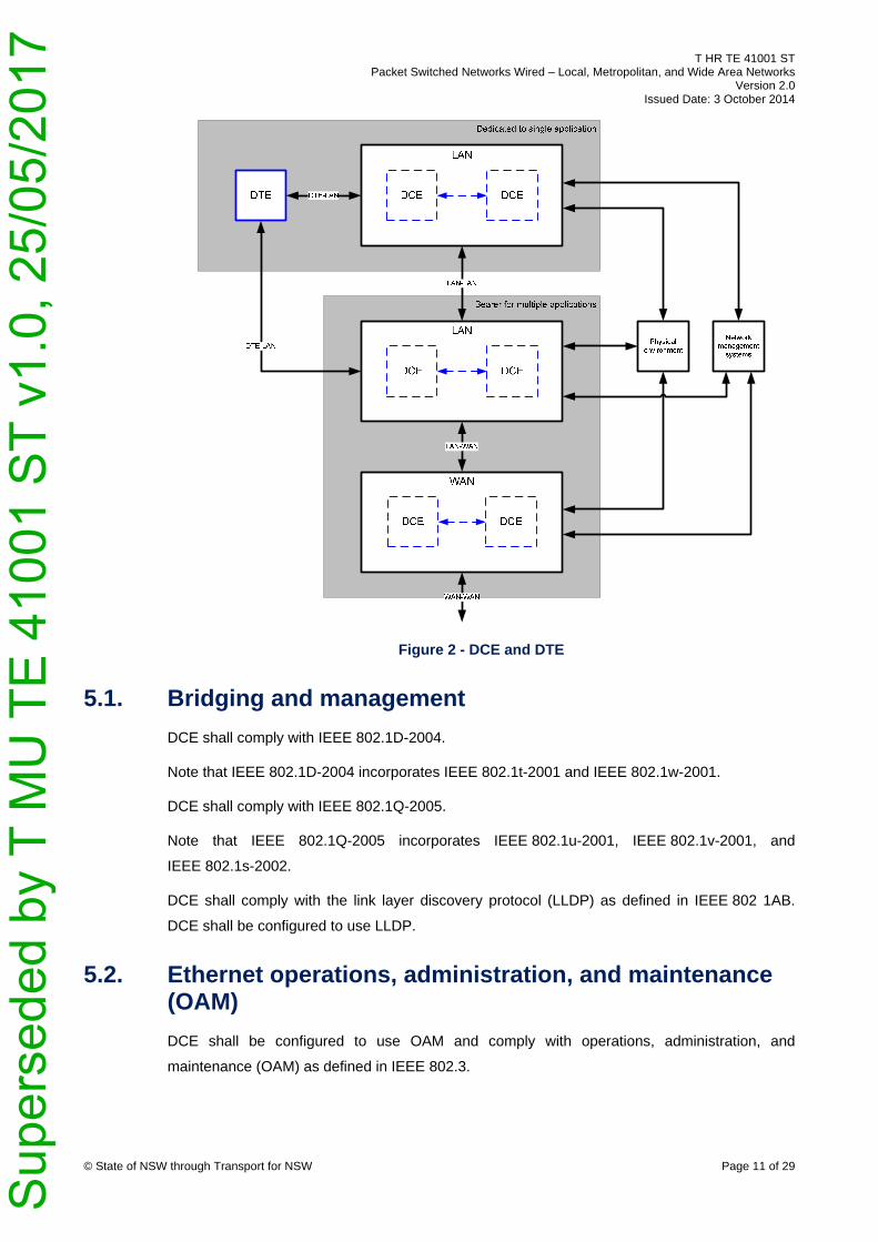
Figure 2 shows the data communication equipment (DCE) and data terminal equipment (DTE)
in the overall system. The functional requirements are specified in Section 5.1 through Section
5.15.
Sup
erse
ded
by T
MU
TE
410
01 S
T v1
.0, 2
5/05
/201
7
T HR TE 41001 ST Packet Switched Networks Wired – Local, Metropolitan, and Wide Area Networks
Version 2.0 Issued Date: 3 October 2014
© State of NSW through Transport for NSW Page 11 of 29
Figure 2 - DCE and DTE
5.1. Bridging and management
DCE shall comply with IEEE 802.1D-2004.
Note that IEEE 802.1D-2004 incorporates IEEE 802.1t-2001 and IEEE 802.1w-2001.
DCE shall comply with IEEE 802.1Q-2005.
Note that IEEE 802.1Q-2005 incorporates IEEE 802.1u-2001, IEEE 802.1v-2001, and
IEEE 802.1s-2002.
DCE shall comply with the link layer discovery protocol (LLDP) as defined in IEEE 802 1AB.
DCE shall be configured to use LLDP.
5.2. Ethernet operations, administration, and maintenance (OAM)
DCE shall be configured to use OAM and comply with operations, administration, and
maintenance (OAM) as defined in IEEE 802.3.
Sup
erse
ded
by T
MU
TE
410
01 S
T v1
.0, 2
5/05
/201
7
T HR TE 41001 ST Packet Switched Networks Wired – Local, Metropolitan, and Wide Area Networks
Version 2.0 Issued Date: 3 October 2014
© State of NSW through Transport for NSW Page 12 of 29
5.3. 10 Mb/s ethernet interfaces
Where a DCE provides 10 Mb/s ethernet interface this section has to be complied with.
10BASE-T type 10 Mb/s ethernet interfaces as defined in IEEE 802.3 may be integrated into
cards, shelves, or chassis.
DTE may provide 10BASE-T type 10 Mb/s ethernet interfaces as defined in IEEE 802.3.
5.4. 100 Mb/s ethernet interfaces
Where a DCE provides 100 Mb/s ethernet interfaces, this section has to be complied with.
DCE that provide 100 Mb/s ethernet interfaces using modular transceiver packages shall
comply with the media independent interface (MII) as defined in IEEE 802.3.
100BASE-TX type 100 Mb/s ethernet interfaces as defined in IEEE 802.3 may be integrated
into cards, shelves, or chassis. Other 100 Mb/s ethernet interface types shall be provided using
modular transceiver packages.
DTE may provide 100BASE-TX type 100 Mb/s ethernet interfaces as defined in IEEE 802.3.
5.5. 1 Gb/s ethernet interfaces
Where a DCE provides 1 Gb/s ethernet interfaces this section has to be complied with.
DCE that provide 1 Gb/s ethernet interfaces using modular transceiver packages shall comply
with the gigabit media independent interface (GMII) as defined in IEEE 802.3.
1000BASE-T type 1 Gb/s ethernet interfaces as defined in IEEE 802.3 may be integrated into
cards, shelves, or chassis. Other 1 Gb/s ethernet interface types shall be provided using
modular transceiver packages.
DTE may provide 1000BASE-T type 1 Gb/s ethernet interfaces as defined in IEEE 802.3.
Modular transceiver packages shall be available that comply with the following 1 Gb/s ethernet
interface types as defined in IEEE 802.3:
• 1000BASE-T
• 1000BASE-LX
• 1000BASE-SX
• 1000BASE-LX10
• 1000BASE-BX10
Non-standard 1 Gb/s ethernet interfaces may be used if greater distances are required,
provided that equivalent product can be sourced from at least three suppliers.
Sup
erse
ded
by T
MU
TE
410
01 S
T v1
.0, 2
5/05
/201
7
T HR TE 41001 ST Packet Switched Networks Wired – Local, Metropolitan, and Wide Area Networks
Version 2.0 Issued Date: 3 October 2014
© State of NSW through Transport for NSW Page 13 of 29
5.6. 10 Gb/s ethernet interfaces
Where a DCE provides10 Gb/s ethernet interfaces this section shall be complied with.
DCE that provide 10 Gb/s ethernet interfaces using modular transceiver packages shall comply
with the 10 gigabit media independent interface (XGMII) as defined in IEEE 802.3.
All 10 Gb/s ethernet interface types shall be provided using modular transceiver packages.
Modular transceiver packages shall be available that comply with the following 10 Gb/s ethernet
interface types as defined in IEEE 802.3:
• 10GBASE-SR
• 10GBASE-LR
• 10GBASE-ER
IEEE 802.3 10GBASE-CR direct attach copper cables may be used within a LAN or WAN
system for direct DCE to DCE connections.
Non-standard 10 Gb/s ethernet interfaces may be used if greater distances are required,
provided that equivalent product can be sourced from at least three suppliers.
5.7. 40 Gb/s ethernet interfaces
Where a DCE provides 40 Gb/s ethernet interfaces this section shall be complied with.
DCE that provide 40 Gb/s ethernet interfaces using modular transceiver packages shall comply
with the 40 gigabit media independent interface (XLGMII) as defined in IEEE 802.3.
All 40 Gb/s ethernet interface types shall be provided using modular transceiver packages.
Modular transceiver packages shall be available that comply with the following 40 Gb/s ethernet
interface types as defined in IEEE 802.3:
• 40GBASE-SR4
• 40GBASE-LR4
IEEE 802.3 40GBASE-CR4 direct attach copper cables may be used within a LAN or WAN
system for direct DCE to DCE connections.
Non-standard 40 Gb/s ethernet interfaces may be used if greater distances are required
provided that equivalent product can be sourced from at least three suppliers.
Sup
erse
ded
by T
MU
TE
410
01 S
T v1
.0, 2
5/05
/201
7
T HR TE 41001 ST Packet Switched Networks Wired – Local, Metropolitan, and Wide Area Networks
Version 2.0 Issued Date: 3 October 2014
© State of NSW through Transport for NSW Page 14 of 29
5.8. 100 Gb/s ethernet interfaces
Where a DCE provides 100 Gb/s ethernet interfaces this section has to be complied with.
100 Gb/s ethernet interfaces shall not be used.
Note that 100 Gb/s ethernet interfaces may be reviewed for inclusion in the next
revision of this standard.
5.9. Power over ethernet
LAN DCE that provide power over ethernet (PoE) ports shall comply as a power sourcing
equipment (PSE) with the data terminal equipment (DTE) power via media dependant interface
(MDI) as defined in IEEE 802.3.
DTE may comply as a powered device (PD) with the data terminal equipment (DTE) power via
media dependant interface (MDI) as defined in IEEE 802.3.
Note that IEEE 802.3 incorporates IEEE 802.3af-2003 and IEEE 802.3at-2009.
5.10. Modular transceiver packages
The following is a list of compliant modular transceiver packages for use in DCE and DTE:
• small form factor pluggable (SFP) transceiver compliant to INF-8074i
• enhanced small form factor pluggable (SFP+) transceiver compliant to SFF-8431
• 10 gigabit small form factor pluggable (XFP) transceiver compliant to INF-8077i
• 10 Gb/s 4X pluggable transceiver (QSFP+) transceiver compliant to SFF-8635
Other modular transceiver packages shall not be used.
5.11. Port-based network access control
LAN DCE shall comply with IEEE 802.1X as an authenticator.
5.12. Internet protocol and internet control message protocol
WAN DCE and DTE shall comply with internet protocol (IP) and internet control message
protocol (ICMP) as defined in IETF STD 5.
5.13. First hop redundancy protocol
WAN DCE shall comply with virtual router redundancy protocol (VRRP) as defined in
IETF RFC 3768.
Sup
erse
ded
by T
MU
TE
410
01 S
T v1
.0, 2
5/05
/201
7

T HR TE 41001 ST Packet Switched Networks Wired – Local, Metropolitan, and Wide Area Networks
Version 2.0 Issued Date: 3 October 2014
© State of NSW through Transport for NSW Page 15 of 29
5.14. Exterior gateway protocol
WAN DCE shall comply with border gateway protocol (BGP) as defined in IETF RFC 4271.
5.15. Quality of service
DCE shall support weighted round robin (WRR) and strict priority (SP) congestion management
mechanisms.
DCE shall support random early detection (RED) congestion avoidance mechanisms.
DCE shall support policed rate-limiting and packet actions (for example: transmit, drop, remark)
for conforming and exceeding rates based on traffic transmitted on a particular interface or
defined by an access control list (ACL).
6. Network interfaces between DTE, LAN and WAN systems
Figure 3 shows the network interfaces between DTE, LAN, and WAN systems and includes the
following:
• data terminal equipment to local area network (DTE to LAN systems)
• local area network to local area network (LAN to LAN systems)
• local area network to wide area network (LAN to WAN systems)
• wide area network to wide area network (WAN to WAN systems)
These interfaces are explained in Section 6.1, Section 6.2, Section 6.3, and Section 6.4
respectively.
Sup
erse
ded
by T
MU
TE
410
01 S
T v1
.0, 2
5/05
/201
7
T HR TE 41001 ST Packet Switched Networks Wired – Local, Metropolitan, and Wide Area Networks
Version 2.0 Issued Date: 3 October 2014
© State of NSW through Transport for NSW Page 16 of 29
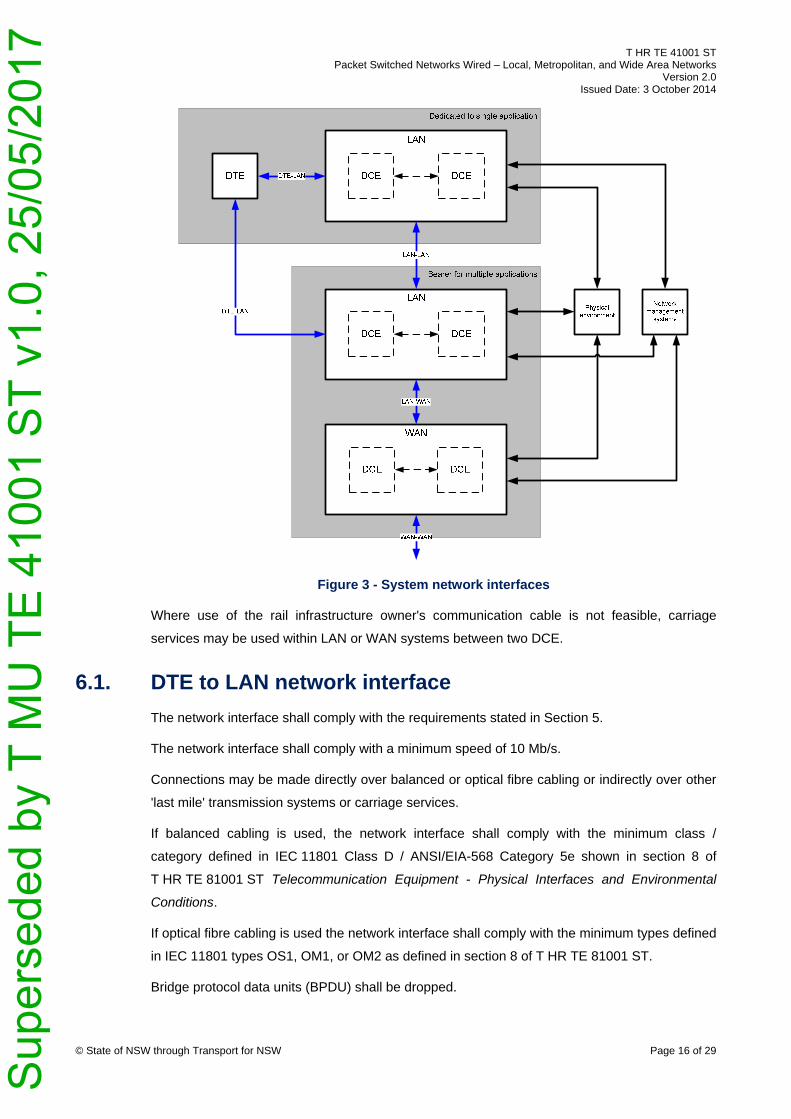
Figure 3 - System network interfaces
Where use of the rail infrastructure owner's communication cable is not feasible, carriage
services may be used within LAN or WAN systems between two DCE.
6.1. DTE to LAN network interface
The network interface shall comply with the requirements stated in Section 5.
The network interface shall comply with a minimum speed of 10 Mb/s.
Connections may be made directly over balanced or optical fibre cabling or indirectly over other
'last mile' transmission systems or carriage services.
If balanced cabling is used, the network interface shall comply with the minimum class /
category defined in IEC 11801 Class D / ANSI/EIA-568 Category 5e shown in section 8 of
T HR TE 81001 ST Telecommunication Equipment - Physical Interfaces and Environmental
Conditions.
If optical fibre cabling is used the network interface shall comply with the minimum types defined
in IEC 11801 types OS1, OM1, or OM2 as defined in section 8 of T HR TE 81001 ST.
Bridge protocol data units (BPDU) shall be dropped.
Sup
erse
ded
by T
MU
TE
410
01 S
T v1
.0, 2
5/05
/201
7
T HR TE 41001 ST Packet Switched Networks Wired – Local, Metropolitan, and Wide Area Networks
Version 2.0 Issued Date: 3 October 2014
© State of NSW through Transport for NSW Page 17 of 29
6.2. LAN to LAN network interface
The network interface shall comply with the requirements stated in Section 5.
The network interface shall comply with a minimum speed of 1 Gb/s.
The network interface shall comply with the minimum types defined in IEC 11801 types OS1,
OM3, or OM4 as defined in section 8 of T HR TE 81001 ST, or direct attach copper.
The network interface shall be provided by modular transceiver package.
Quality of service markings shall use the IEEE 802.1Q-2005 priority code point (PCP) field.
Bridge protocol data units (BPDU) shall be dropped.
6.3. LAN to WAN network interface
The network interface shall comply with the requirements stated in Section 5.
The network interface shall comply with a minimum speed of 1 Gb/s.
The network interface shall comply with the minimum types defined in IEC 11801 types OS1,
OM3, or OM4 as defined in section 8 of T HR TE 81001 ST, or direct attach copper.
The network interface shall be provided by modular transceiver package.
Quality of service markings shall use the IEEE 802.1Q-2005 priority code point (PCP) field.
VRRP shall be used as the first hop redundancy protocol.
6.4. WAN to WAN network interface
The network interface shall comply with the requirements stated in Section 5.
The network interface shall comply with a minimum speed of 10 Gb/s.
The network interface shall comply with the minimum types defined in IEC 11801 types OS1,
OM3, or OM4 as defined in section 8 of T HR TE 81001 ST.
The network interface shall be provided by modular transceiver package.
Quality of service markings shall use the IETF RFC 2474 differentiated services (DS) field.
BGP shall be used as the exterior gateway protocol.
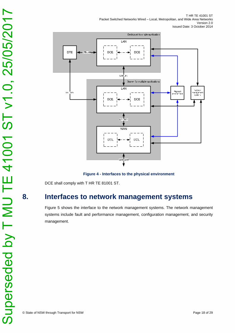
7. Interfaces to physical environment
Figure 4 shows the interfaces to the physical environment. The physical environment includes
power supply, earth connections, rack and rail mounts, equipment cords, environmental
conditions and electromagnetic emissions and immunity.
Sup
erse
ded
by T
MU
TE
410
01 S
T v1
.0, 2
5/05
/201
7
T HR TE 41001 ST Packet Switched Networks Wired – Local, Metropolitan, and Wide Area Networks
Version 2.0 Issued Date: 3 October 2014
© State of NSW through Transport for NSW Page 18 of 29
Figure 4 - Interfaces to the physical environment
DCE shall comply with T HR TE 81001 ST.
8. Interfaces to network management systems
Figure 5 shows the interface to the network management systems. The network management
systems include fault and performance management, configuration management, and security
management.
Sup
erse
ded
by T
MU
TE
410
01 S
T v1
.0, 2
5/05
/201
7

T HR TE 41001 ST Packet Switched Networks Wired – Local, Metropolitan, and Wide Area Networks
Version 2.0 Issued Date: 3 October 2014
© State of NSW through Transport for NSW Page 19 of 29
Figure 5 - Interfaces to network management systems
Where a LAN is dedicated to a single application, full compliance to this section may not be
required if it can be demonstrated that it is not feasible to implement network management
systems based on these protocols. For example, emergency, alert, and critical events in signal
applications may be carried by a proprietary protocol to a monitoring centre because the LAN is
isolated.
The design of network management systems is not mandated in this standard. Depending on
the application, it may be appropriate to design network management systems that are local,
remote or both. For example, rolling stock applications may implement an embedded local
syslog server within the DCE because a wireless wide area network may not be reliable.
DCE shall comply with T HR TE 81002 ST Telecommunications Equipment – Network
Management.
LAN DCE shall be configured as a port-based network access control (PNAC) authenticator
compliant to IEEE 802.1X.
Sup
erse
ded
by T
MU
TE
410
01 S
T v1
.0, 2
5/05
/201
7
T HR TE 41001 ST Packet Switched Networks Wired – Local, Metropolitan, and Wide Area Networks
Version 2.0 Issued Date: 3 October 2014
© State of NSW through Transport for NSW Page 20 of 29
9. Non-functional requirements for wired packet switched networks
The non-functional requirements specify the following performance requirements for wired
packet switched networks:
• availability
• interoperability
• maintainability
• manageability
• performance
• reliability
• work, health, and safety
• security
9.1. Availability
Unless otherwise qualified in this section, availability refers to the 'operational' and 'steady state'
availability inclusive of all factors that contribute to system down time within the operational
conditions, such as the physical environment and network management systems defined in
Section 7 and Section 8 of this document.
A service is defined as a connection between two boundary interfaces on a system.
Network availability (AN) is the availability of one or more LAN or WAN systems as defined
below:
• probability that a typical service is able to make a connection across a network
• percentage of services able to make connections across a network at a given time
• percentage of time a typical service is able to make connections across a network
All these definitions are considered equivalent because they will provide identical network
availability values even though they are viewing a network from different perspectives: a service
connection, all service connections, and service downtime.
Recovery time (Tr) is defined as the maximum time for the system to reconverge in the event of
a failure or recovery from a failure for failure modes where the LAN or WAN system has been
designed to automatically reconverge (for example by using redundant sub-systems).
Sup
erse
ded
by T
MU
TE
410
01 S
T v1
.0, 2
5/05
/201
7

T HR TE 41001 ST Packet Switched Networks Wired – Local, Metropolitan, and Wide Area Networks
Version 2.0 Issued Date: 3 October 2014
© State of NSW through Transport for NSW Page 21 of 29
Where an application cannot tolerate a loss of traffic forwarding of duration Tr, the application
shall implement alternate mechanisms to automatically restore traffic forwarding within the
required time.
Table 1 shows the minimum availability requirements for safety related function and non-safety
related function.
The availability from a typical connection between two DTE (bounded by the DTE-facing port on
the DCE) shall be not less than 99.99% for safety-related functions and 99.9% for non
safety-related functions.
Table 1 - Minimum availability requirements
System AN(system)
safety-related
AN(system)
non safety-related
Tr(system)
LAN 99.998 99.98 20 s
WAN 99.9995 99.9995 300 ms
Availability shall be demonstrated by the reliability block diagram (RBD) method as part of the
reliability, availability, and maintainability (RAM) programme.
9.2. Interoperability
Where no specific requirement exists, open standards shall be complied with instead of
proprietary alternatives.
Interoperability with nominated type approved DCE or existing operators' DCE shall be verified
by testing the systems, which complies to T MU TE 81003 ST Test Processes and
Documentation for Programmable Electronic Systems and Software as part of the verification
plan. This is in addition to other verification methods such as certification that may form part of
the verification plan.
Additional interoperability requirements shall be complied with where new DCE interface with
existing operators' systems additional interoperability requirements may exist.
Where used, DCE shall interoperate with any compliant modular transceiver package from any
third party. If a third-party modular transceiver package is used the DCE shall not disable or
degrade its performance and the DCE supplier shall not alter the support or warranty conditions
for the DCE.
Sup
erse
ded
by T
MU
TE
410
01 S
T v1
.0, 2
5/05
/201
7
T HR TE 41001 ST Packet Switched Networks Wired – Local, Metropolitan, and Wide Area Networks
Version 2.0 Issued Date: 3 October 2014
© State of NSW through Transport for NSW Page 22 of 29
9.3. Maintainability
Preventative maintenance programs shall be identified for all components with an increasing
failure rate (IFR) failure model such as fans, filters, transceivers, and connectors.
Maintenance programs shall be identified to detect imminent or conditional failures such as
thresholds for CPU and memory, interface utilisation and errors, temperature, power supply
current and voltage.
Maintenance programs shall be identified for all assets to ensure that the hardware, firmware,
software, physical and logical configuration is as designed throughout the life of the asset.
Where installed in a redundant configuration, cards and modules shall be able to be inserted or
removed without affecting system operation, that is, hot swappable. Hot swapping shall be
performed in hardware without issuing any system commands.
Cards and modules shall be held firmly in place by latches or thumbscrews.
Cards and modules shall be able to be inserted or removed without the use of specialised or
proprietary tools.
The time to physically interchange faulty cards or modules, which includes repatching cables,
shall not exceed 15 minutes.
All message logs with a severity level between 0 and 4 inclusive as defined in IETF RFC 5424
shall be logged to syslog.
All message logs with a severity level between 0 and 2 inclusive as defined in IETF RFC 5424
shall be regarded as failures requiring immediate corrective action.
All message logs with a severity level of 3 or 4 as defined in IETF RFC 5424 shall be regarded
as conditional failures requiring priority preventative action.
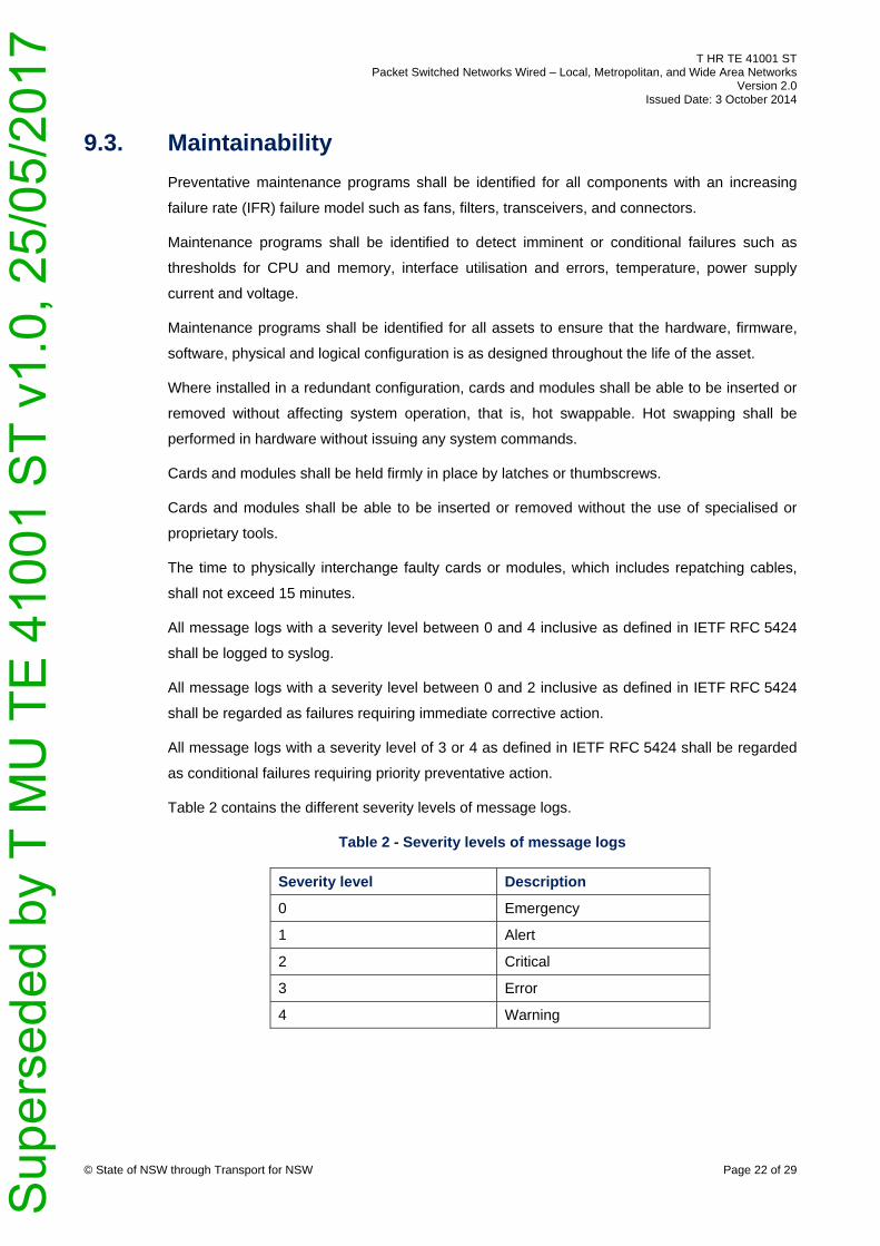
Table 2 contains the different severity levels of message logs.
Table 2 - Severity levels of message logs
Severity level Description
0 Emergency
1 Alert
2 Critical
3 Error
4 Warning
Sup
erse
ded
by T
MU
TE
410
01 S
T v1
.0, 2
5/05
/201
7

T HR TE 41001 ST Packet Switched Networks Wired – Local, Metropolitan, and Wide Area Networks
Version 2.0 Issued Date: 3 October 2014
© State of NSW through Transport for NSW Page 23 of 29
9.4. Manageability
Configuration datastore, running configuration datastores and startup configuration datastores
are defined in IETF RFC 6241. DCE are not required to support or use IETF RFC 6241.
DCE shall support the following logical configuration management capabilities:
• support separate running and startup configuration datastores
• retrieve all of a configuration datastore
• load all of a configuration to a target configuration datastore
• create or replace a configuration datastore with the contents of another configuration
datastore
• delete a configuration datastore
• retrieve running configuration
When queried using SNMPv3, the DCE returns values that correspond with configured values
for the following logical configuration attributes:
• hostname (sysName)
• location (sysLocation)
• contact (sysContact)
When queried using SNMPv3, the DCE returns values that correspond with published product
documentation for the following physical configuration attributes:
• hardware revision
• firmware revision
• software revision
• serial number of chassis and field replaceable units
• manufacturer name of chassis and field replaceable units
• model name of chassis and field replaceable units
Sup
erse
ded
by T
MU
TE
410
01 S
T v1
.0, 2
5/05
/201
7
T HR TE 41001 ST Packet Switched Networks Wired – Local, Metropolitan, and Wide Area Networks
Version 2.0 Issued Date: 3 October 2014
© State of NSW through Transport for NSW Page 24 of 29
9.5. Performance
Throughput, latency, and frame loss rate are defined in IETF RFC 1242.
DCE shall be tested against the procedure defined in IETF RFC 2544 for throughput, latency,
and frame loss rate and obtain the following test results:
• throughput of 100% with line rate equal to 100%
• latency of less than:
o 130 µs for a 1518 byte frame on a 100 Mb/s ethernet interface
o 18 µs for a 1518 byte frame on a 1 Gb/s ethernet interface
o 6.5 µs for a 1518 byte frame on a 10 Gb/s ethernet interface
• frame loss rate of 0% with line rate equal to 100%
Delay and delay variance metrics are inclusive of transmission, switch fabric, queuing and
propagation delays.
A connection between two DTE shall have an average delay of 5 ms and delay variance of 5 ms
for a 1518 byte frame under a load of 80%. It is assumed a maximum of two 100 Mb/s 100 m
links and 20 one Gb/s 1 km links modelled using M/M/1 distribution and 80% load.
All traffic flows shall be assigned a relative priority and information rates as part of a traffic policy
and serviced by DCE accordingly.
DCE shall be configured to ensure that safety-related traffic flows are serviced preferentially
over non safety-related traffic flows.
9.6. Reliability
Failure models inclusive of the failure distribution and required parameters for all field
replaceable units (FRU) that comprise DCE shall be specified. For example, a common failure
model is the constant failure rate (CFR) with exponential distribution and mean time to failure
(MTTF).
The mean time to failure of all CFR field replaceable units shall exceed 150,000 h.
Failure model parameters shall comply with the yearly average temperature for reliability,
availability, maintainability, and safety (RAMS) calculations defined in EN 50125-3.
Acceptable methods for predicting the failure model for electronic equipment are as follows:
• IEC/TR 62380
• Telcordia SR-332 Issue 3
• MIL-HDBK-217F Notice 2
Sup
erse
ded
by T
MU
TE
410
01 S
T v1
.0, 2
5/05
/201
7
T HR TE 41001 ST Packet Switched Networks Wired – Local, Metropolitan, and Wide Area Networks
Version 2.0 Issued Date: 3 October 2014
© State of NSW through Transport for NSW Page 25 of 29
Where multiple MTTF estimates are available, the lowest estimate shall be used.
Failure models shall be justified by stating the data source, methodology, environment,
assumptions, and parameters.
9.7. Work, health, and safety
DCE shall comply with the safety of information technology requirements as defined in
EN 60950-1.
DCE shall comply with the safety of laser products requirements as defined in EN 60825-1 and
EN 60825-2.
9.8. Security
Defences against security vulnerabilities such as interruption, interception, modification,
intrusion, and deception shall be implemented consistent with the guidance contained within
ISO/IEC 18028. These defences shall mitigate internal or external and intentional or
unintentional security vulnerabilities.
The governance of LAN and WAN system shall comply with ISO/IEC 27001.
9.8.1. Management-plane security
Where a LAN is dedicated to a single application, full compliance to this section may not be
required if it can be demonstrated that it is not feasible to implement network management
systems based on the protocols defined in Section 8 of this document.
As a minimum, the following management-plane security defences shall be implemented on
DCE:
• in-band management ports to be on dedicated management VLAN (not VLAN 1)
• prune management VLAN from 802.1Q trunks where not required
• enable password security (hashing) for local passwords
• disable local password recovery using the console, that is, the DCE is factory reset to
reinitialise
• disable all unused services, such as discard, daytime, chargen and protocols, such as
SNMPv1, SNMPv2
• enable an idle timeout of 5 minutes on console and remote terminal sessions
• enable the generation of a trap or message notification when memory utilisation exceeds
80%
Sup
erse
ded
by T
MU
TE
410
01 S
T v1
.0, 2
5/05
/201
7
T HR TE 41001 ST Packet Switched Networks Wired – Local, Metropolitan, and Wide Area Networks
Version 2.0 Issued Date: 3 October 2014
© State of NSW through Transport for NSW Page 26 of 29
Enabling the generation of a message notification when memory and CPU utilisation
thresholds have been exceeded assists in detecting that a security attack is in progress.
• enable the generation of a trap or message notification when CPU utilisation exceeds 80%
• enable authentication in protocols where the support exists; for example, NTPv3, SNMPv3
• enable encryption in protocols where the support exists; for example, SNMPv3
• access control list 'white-list' is implemented to permit access to the DCE
management-plane services, such as SNMPv3, syslog, DNS, NTPv3, SNTP, SSHv2,
HTTPS, TACACS+, RADIUS from authorised network management servers and clients
All other access to management-plane services is denied.
• access control list 'white-list' is implemented to permit access to the DCE using internet
control message protocol (ICMP) types 0, 8, and 11 from authorised network management
servers and clients.
All other access to the DCE using ICMP types 0, 8, and 11 is denied.
• access to management services are restricted to configured interfaces
• disable insecure management protocols, such as trivial file transfer protocol (TFTP), telnet
• enable a retry limit for protocols that support authentication
• disable any auxiliary or unused management ports
• enable the banner as shown below on login to notify unauthorised users that they are not
permitted to use the system:
***** This service is for authorised clients only *****
***************************************************************
* WARNING: It is a criminal offence to: *
* i. Obtain access to data without authority *
* (Penalty 2 years imprisonment) *
* ii Damage, delete, alter or insert data without authority *
* (Penalty 10 years imprisonment) *
***************************************************************
• configure the primary method of authentication, authorisation and accounting to TACACS+
or RADIUS
• configure the secondary method of authentication, in the event of the failure of the primary
method, to local passwords
Sup
erse
ded
by T
MU
TE
410
01 S
T v1
.0, 2
5/05
/201
7
T HR TE 41001 ST Packet Switched Networks Wired – Local, Metropolitan, and Wide Area Networks
Version 2.0 Issued Date: 3 October 2014
© State of NSW through Transport for NSW Page 27 of 29
• manufacturer default passwords shall not be used
• configure logging of messages with a severity level between 0 and 4 inclusive, as defined
in IETF RFC 5424, to syslog servers
• disable logging of messages to console and terminal
• enable logging of configuration change, authentication and authorisation events
9.8.2. Control-plane security
As a minimum, the following control-plane security defences shall be implemented on DCE:
• access control list 'white-list' is implemented to permit access to the control-plane. For
example, VRRP and BGP.
All other access to the control-plane is denied.
• enable authentication in protocols where the support exists; for example, VRRP and BGP
• enable route filtering using prefix lists where the support exists; for example, BGP
9.8.3. Data-plane security
Where a LAN is dedicated to a single application, full compliance to this section may not be
required if it can be demonstrated that it is not feasible to implement network management
systems based on the protocols defined in Section 8 of this document.
As a minimum, the following data-plane security defences shall be implemented on the system
interface to the first LAN DCE contained within the bearer for multiple applications
super-system:
• prune VLAN 1 from 802.1Q trunks where not required
• where physical access to DCE, DTE, or patch panels cannot be controlled exclusively to
personnel authorised to perform maintenance of LAN and WAN systems, port-based
network access control (PNAC) shall be enabled on all DCE access ports. IEEE 802.1X
shall be used for PNAC where the DTE supports IEEE 802.1X, otherwise strict MAC
address PNAC shall be used. Examples of exceptions may include facilities with electronic
access or keyed access with monitored perimeter alarming.
• enable DCE traffic flow statistics
• access control list 'white-list' is implemented to permit access to data-plane, specified by
internet layer, such as IP, ICMP or transport layer, such as TCP, UDP rules.
All other access to data-plane is denied.
Sup
erse
ded
by T
MU
TE
410
01 S
T v1
.0, 2
5/05
/201
7
T HR TE 41001 ST Packet Switched Networks Wired – Local, Metropolitan, and Wide Area Networks
Version 2.0 Issued Date: 3 October 2014
© State of NSW through Transport for NSW Page 28 of 29
9.9. Scalability
The LAN DCE switching capacity shall switch traffic at full line rate on all interfaces.
9.10. Supportability
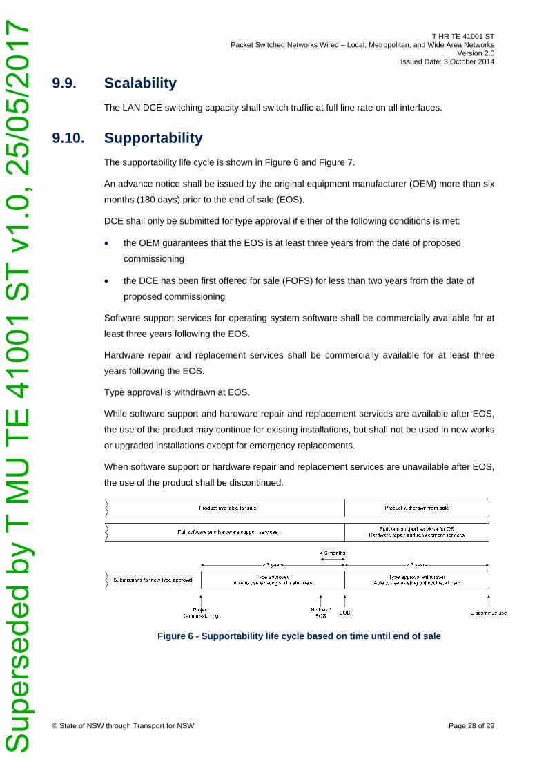
The supportability life cycle is shown in Figure 6 and Figure 7.
An advance notice shall be issued by the original equipment manufacturer (OEM) more than six
months (180 days) prior to the end of sale (EOS).
DCE shall only be submitted for type approval if either of the following conditions is met:
• the OEM guarantees that the EOS is at least three years from the date of proposed
commissioning
• the DCE has been first offered for sale (FOFS) for less than two years from the date of
proposed commissioning
Software support services for operating system software shall be commercially available for at
least three years following the EOS.
Hardware repair and replacement services shall be commercially available for at least three
years following the EOS.
Type approval is withdrawn at EOS.
While software support and hardware repair and replacement services are available after EOS,
the use of the product may continue for existing installations, but shall not be used in new works
or upgraded installations except for emergency replacements.
When software support or hardware repair and replacement services are unavailable after EOS,
the use of the product shall be discontinued.
Figure 6 - Supportability life cycle based on time until end of sale
Sup
erse
ded
by T
MU
TE
410
01 S
T v1
.0, 2
5/05
/201
7

T HR TE 41001 ST Packet Switched Networks Wired – Local, Metropolitan, and Wide Area Networks
Version 2.0 Issued Date: 3 October 2014
© State of NSW through Transport for NSW Page 29 of 29
Figure 7 - Supportability life cycle based on time from first offered for sale
9.11. Sustainability
DCE shall comply with the restriction of hazardous substances (RoHS) directive requirements
as defined in EU 2002/95/EC.
When configured with the maximum supported ports the power consumption shall not exceed
5 W on average per port excluding any power over ethernet loads.
Sup
erse
ded
by T
MU
TE
410
01 S
T v1
.0, 2
5/05
/201
7