page 1 of 26 - ernest maier, inc rigid diaphragm is assumed to distribute ... maximum span-to-width...
TRANSCRIPT

Technical Notes 24C - The Contemporary Bearing Wall - Introduction to Shear Wall Design[Sept./Oct. 1970] (Reissued May 1988)
INTRODUCTION
The general design concept of the contemporary bearing wall building system depends upon the combined structuralaction of the floor and roof systems with the walls. The floor system carries vertical loads and, acting as a diaphragm,lateral loads to the walls for transfer to the foundation. Lateral forces of wind and earthquake are usually resisted by shearwalls which are parallel to the direction of the lateral load. These shear walls, by their shearing resistance and resistanceto overturning, transfer the lateral loads to the foundation. See Fig. 1.
Shear Wall Action
FIG. 1
It is the purpose of this Technical Notes to discuss some of the factors involved in the design of brick masonry shear walls
Page 1 of 26
10/18/2010http://www.gobrick.com/BIA/technotes/t24c.htm

and to present some of the available test data regarding their strength. Other issues of Technical Notes will containexamples relating to the design of brick masonry shear walls.
LATERAL FORCES
The principal lateral forces to be considered in the design of shear walls are wind pressure and earthquake. Most buildingcodes and engineering practice standards specify that wind and earthquake may be assumed never to occursimultaneously.
Wind Pressure. Building codes usually specify design wind load requirements which should be considered minimum. Foradditional information on wind pressure, the designer may refer to the American Standard Building Code Requirementsfor Minimum Design Loads in Buildings and Other Structures, A58.1 - 1955, and "Wind Forces on Structures", ASCETransactions, Vol. 126, Part II, 1961.
Earthquake. Unlike wind pressure, earthquake forces on a structure are considered a function of the mass and stiffnessof the structure. Generally speaking, subject to dynamic phenomena, the greater the weight and rigidity of the structure -the greater are the forces which must be resisted by the structure. It is, therefore, current engineering practice to design"box systems" (structures without complete vertical load-carrying space frames) to resist the greater lateral forces. In thistype of structural system the lateral forces are resisted by the shear walls. The Uniform Building Code, 1970 edition,contains the following requirements pertaining to minimum earthquake forces for structures:
Every structure shall be designed and constructed to withstand minimum total lateral seismic forces assumed to actnonconcurrently in the direction of each of the main axes of the structure in accordance with the following formula:
V = Z K C W
where:
V = total lateral load or shear at the base
Z = numerical coefficient dependent upon the zone of seismic activity:
Z = 1/4 for Zone 1 (minor damage);
Z = 1/2 for Zone 2 (moderate damage);
Z = 1 for Zone 3 (major damage)
K = numerical coefficient from Table 1
C = numerical coefficient dependent on fundamental period of vibration of thestructure (in seconds) in the direction considered
W = total dead load of the structure.
Page 2 of 26
10/18/2010http://www.gobrick.com/BIA/technotes/t24c.htm
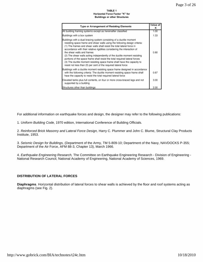
For additional information on earthquake forces and design, the designer may refer to the following publications:
1. Uniform Building Code, 1970 edition, International Conference of Building Officials.
2. Reinforced Brick Masonry and Lateral Force Design, Harry C. Plummer and John C. Blume, Structural Clay ProductsInstitute, 1953.
3. Seismic Design for Buildings, (Department of the Army, TM 5-809-10; Department of the Navy, NAVDOCKS P-355;Department of the Air Force, AFM 88-3, Chapter 13), March 1966.
4. Earthquake Engineering Research, The Committee on Earthquake Engineering Research - Division of Engineering -National Research Council, National Academy of Engineering, National Academy of Sciences, 1969.
DISTRIBUTION OF LATERAL FORCES
Diaphragms. Horizontal distribution of lateral forces to shear walls is achieved by the floor and roof systems acting asdiaphragms (see Fig. 2).
Page 3 of 26
10/18/2010http://www.gobrick.com/BIA/technotes/t24c.htm

Diaphragm Action
FIG. 2
To qualify as a diaphragm, a floor and roof system must be able to transmit the lateral forces to the shear walls withoutexceeding a deflection which would cause distress to any vertical element. The successful action of a diaphragm alsorequires that it be properly tied into the supporting shear walls. The designer should insure this action by appropriatedetailing at the juncture between horizontal and vertical structural elements of the building.
Diaphragms may be considered as analogous to horizontal (or inclined, in the case of some roofs) plate girders. The roofor floor slab constitutes the web; the joists, beams and girders function as stiffeners; and the walls or bond beams act asflanges.
Diaphragms may be constructed of materials such as concrete, wood or metal in various forms. Combinations of suchmaterials are also possible. Where a diaphragm is made up of units such as plywood, precast concrete planks or steeldeck units, its characteristics are, to a large degree, dependent upon the attachments of one unit to another and to thesupporting members. Such attachments must resist shearing stresses due to internal translational and rotational actions.
The stiffness of a horizontal diaphragm affects the distribution of the lateral forces into the shear walls. No diaphragm isinfinitely rigid or flexible. However, for the purpose of analysis, diaphragms may be classified into three groups: rigid,semirigid or semiflexible, and flexible.
A rigid diaphragm is assumed to distribute horizontal forces to the vertical resisting elements in proportion to their relativerigidities (see Fig. 3).
Page 4 of 26
10/18/2010http://www.gobrick.com/BIA/technotes/t24c.htm
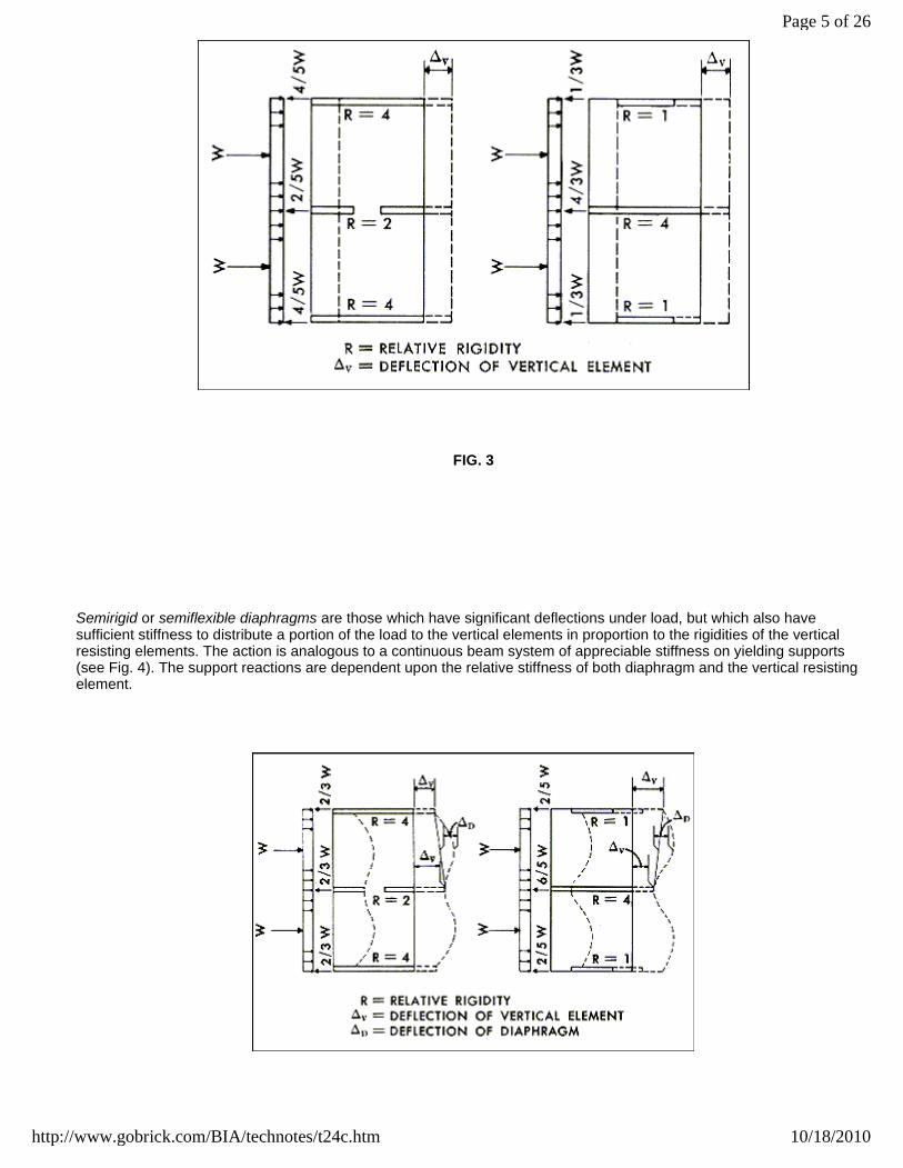
FIG. 3
Semirigid or semiflexible diaphragms are those which have significant deflections under load, but which also havesufficient stiffness to distribute a portion of the load to the vertical elements in proportion to the rigidities of the verticalresisting elements. The action is analogous to a continuous beam system of appreciable stiffness on yielding supports(see Fig. 4). The support reactions are dependent upon the relative stiffness of both diaphragm and the vertical resistingelement.
Page 5 of 26
10/18/2010http://www.gobrick.com/BIA/technotes/t24c.htm

FIG. 4
A flexible diaphragm is analogous to a shear deflecting continuous beam or series of beams spanning between supports.The supports are considered non-yielding, and the relative stiffness of the vertical resisting elements compared to that ofthe diaphragm is great. Thus, a flexible diaphragm is considered to distribute the lateral forces to the vertical resistingelements on a tributary area basis (see Fig. 5).
FIG. 5
Where the center of rigidity of a shear wall system does not coincide with the center of application of the lateral force, thedistribution of the rotational forces due to a torsional moment on the system must also be considered. Where rigid orsemirigid diaphragms are used, it may be assumed that the torsional forces are distributed to the shear walls in directproportion to their relative rigidities and their distance from the center of rigidity (see Fig. 6). In the design provisions forearthquake forces of the 1970 Uniform Building Code, shear resisting elements are required to resist an arbitrary torsionalmoment equivalent to the story shear acting with an eccentricity of not less than five per cent of the maximum buildingdimension at that level. A flexible diaphragm is not considered capable of distributing torsional stresses.
Page 6 of 26
10/18/2010http://www.gobrick.com/BIA/technotes/t24c.htm

Torsional Movement on a Shear Wall System
FIG. 6
Page 7 of 26
10/18/2010http://www.gobrick.com/BIA/technotes/t24c.htm

When dealing with a rigid diaphragm and distributing the horizontal forces to vertical resisting elements in proportion tothe relative rigidities, the relative rigidity of the shear wall is dependent upon the shear and flexural deflections. However,for the proportions of the shear walls in most high-rise buildings, the flexural deflection greatly exceeds the sheardeflection, in which case only flexural rigidity need be considered in determining the relative stiffness of the shear walls.For determination of relative shear and flexural deflections, see Fig. 7.
Relative Shear and Flexural Deflections Determined
for a Uniformly Loaded Cantilever Member of Rectangular Section
FIG. 7
Page 8 of 26
10/18/2010http://www.gobrick.com/BIA/technotes/t24c.htm
A rigorous analysis of the lateral load distribution to the shear wall is sometimes very time-consuming and frequentlyunjustified by the results. Therefore, in many cases a design based on reasonable limits may be used. For example, theload may be distributed by first considering the diaphragm as rigid and then by considering it flexible. If the difference isnot great, the shear wall can then be safely designed for the maximum applied load.
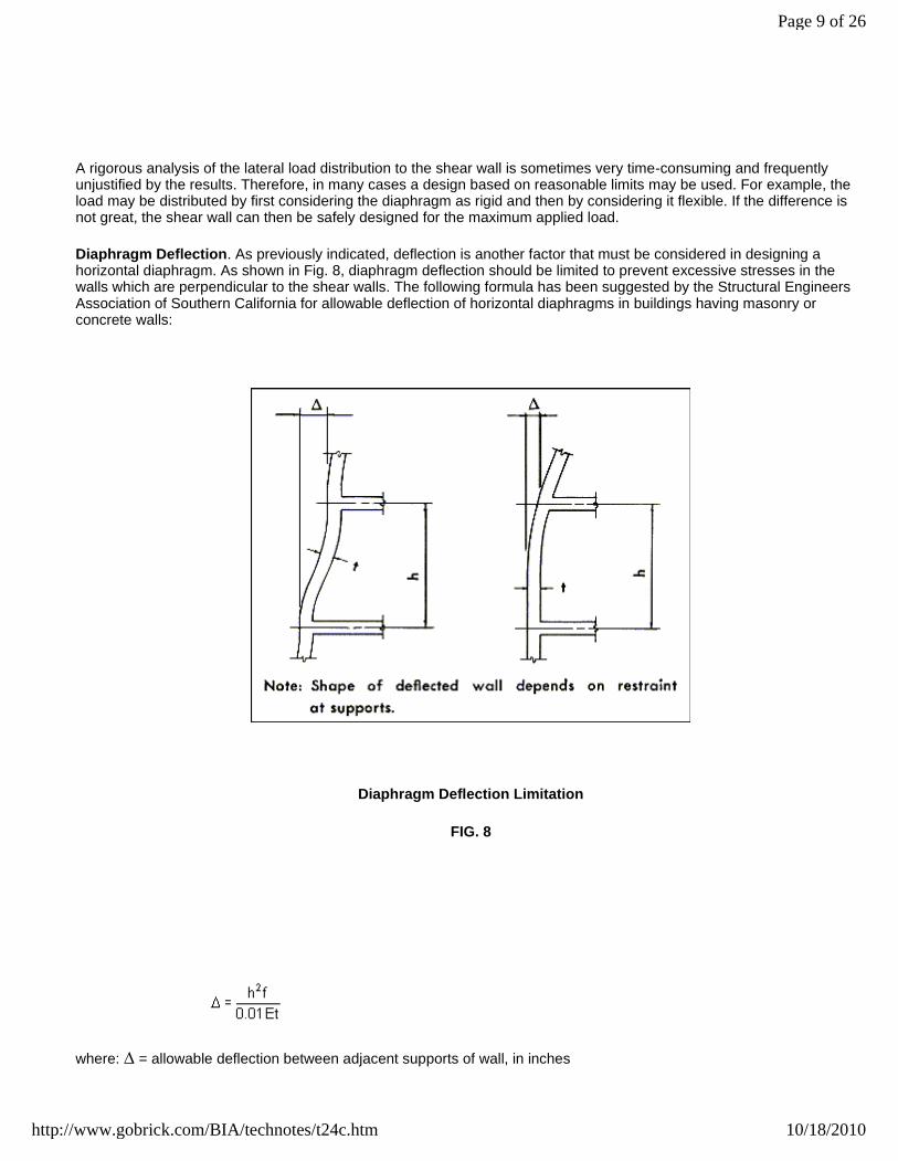
Diaphragm Deflection. As previously indicated, deflection is another factor that must be considered in designing ahorizontal diaphragm. As shown in Fig. 8, diaphragm deflection should be limited to prevent excessive stresses in thewalls which are perpendicular to the shear walls. The following formula has been suggested by the Structural EngineersAssociation of Southern California for allowable deflection of horizontal diaphragms in buildings having masonry orconcrete walls:
Diaphragm Deflection Limitation
FIG. 8
where: = allowable deflection between adjacent supports of wall, in inches
Page 9 of 26
10/18/2010http://www.gobrick.com/BIA/technotes/t24c.htm
h = height of wall between adjacent horizontal supports, in feet
t = thickness of wall, in inches
f = allowable flexural compressive stress of wall material, in pounds per square inch
E = modulus of elasticity of wall material, in pounds per square inch
The application of these limits on deflection must be used with engineering judgment. For example, continuity at floorlevel is assumed, which in many cases is not present due to through-wall flashing. In this situation the deflection may bebased on the allowable compressive stress in the masonry, assuming a reduced cross section of wall. The effect ofreinforcement which may be present in a reinforced brick masonry wall or as a tie to the floor system in a non-reinforcedor partially reinforced masonry wall is not considered. It should also be pointed out that the limit on deflection is actually alimit on differential deflection between two successive floor or diaphragm levels.
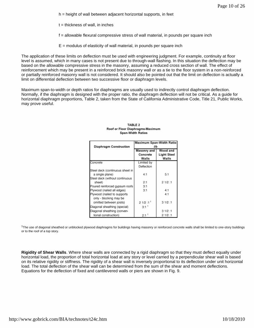
Maximum span-to-width or depth ratios for diaphragms are usually used to indirectly control diaphragm deflection.Normally, if the diaphragm is designed with the proper ratio, the diaphragm deflection will not be critical. As a guide forhorizontal diaphragm proportions, Table 2, taken from the State of California Administrative Code, Title 21, Public Works,may prove useful.
1The use of diagonal sheathed or unblocked plywood diaphragms for buildings having masonry or reinforced concrete walls shall be limited to one-story buildingsor to the roof of a top story.
Rigidity of Shear Walls. Where shear walls are connected by a rigid diaphragm so that they must deflect equally underhorizontal load, the proportion of total horizontal load at any story or level carried by a perpendicular shear wall is basedon its relative rigidity or stiffness. The rigidity of a shear wall is inversely proportional to its deflection under unit horizontalload. The total deflection of the shear wall can be determined from the sum of the shear and moment deflections.Equations for the deflection of fixed and cantilevered walls or piers are shown in Fig. 9.
Page 10 of 26
10/18/2010http://www.gobrick.com/BIA/technotes/t24c.htm

Calculation of Wall Deflections
FIG. 9
Page 11 of 26
10/18/2010http://www.gobrick.com/BIA/technotes/t24c.htm

Where a shear wall contains no openings, the computations for deflection and rigidity are quite simple. In Fig. 10(a), theshear walls are of equal length and rigidity, and each takes one half of the total load. In Fig. 10(b), wall C is one half thelength of wall D and it, therefore, receives less than one eighth of the total load. Where shear walls contain openings suchas doors and windows, the computations for deflection and rigidity are more complex. However, approximate methodshave been developed which may be used. See Fig. 11.
Distribution of Wind Load
FIG. 10
Page 12 of 26
10/18/2010http://www.gobrick.com/BIA/technotes/t24c.htm
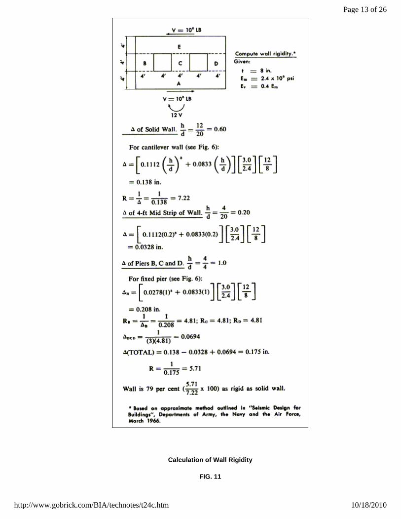
Calculation of Wall Rigidity
FIG. 11
Page 13 of 26
10/18/2010http://www.gobrick.com/BIA/technotes/t24c.htm

To increase the stiffness of shear walls as well as their resistance to bending, intersecting walls or flanges may be used.Very often in the design of buildings, Z, T, U, and I-shape sections develop as natural parts of the design. See Figs. 12and 13. Shear walls with these shapes, of course, have better flexural resistance. The 1969 BIA Standard, Building CodeRequirements for Engineered Brick Masonry, (Sec. 4.7.12A) limits the effective flange width that may be used incalculating flexural stresses. In the case of symmetrical T or I sections, the effective flange width may not exceed onesixth of the total wall height above the level being analyzed. In the case of unsymmetrical L or C sections, the widthconsidered effective may not exceed one sixteenth of the total wall height above the level being analyzed. In either case,the overhang for any section may not exceed six times the flange thickness (see Figs. 14 and 15). It is, of course,necessary to insure that the shear stress at the intersection of the walls does not exceed the permissible shear stress.This will depend on the method used in bonding the two walls together.
Shear Walls of Equivalent Stiffness
FIG. 12
Page 14 of 26
10/18/2010http://www.gobrick.com/BIA/technotes/t24c.htm

Shear Walls With Flanges
FIG. 13
Effective Flange Width
FIG. 14
Page 15 of 26
10/18/2010http://www.gobrick.com/BIA/technotes/t24c.htm

Effective Flange Width
FIG. 15
Coupled Shear Walls. Another method that may be used to increase the stiffness of a bearing wall structure and reducethe possibility of tension developing in shear walls due to wind parallel to the wall is the coupling of collinear shear walls.Figures 16 and 17 indicate the effect of coupling on the stress distribution in the wall due to parallel forces. A flexibleconnection between the walls is assumed in Figs. 16(a) and 17(a), so that the walls act as independent verticalcantilevers in resisting the lateral loads. Figures 16(b) and 17(b) assume the walls to be connected with a more rigidmember which is capable of shear and moment transfer so that a frame-type action results. This can be accomplishedwith a steel, reinforced concrete or reinforced brick masonry section. The plate type action, which is indicated in Figs. 16(c) and 17(c), assumes an extremely rigid connection between walls, such as full story height walls or deep rigidspandrels.
Page 16 of 26
10/18/2010http://www.gobrick.com/BIA/technotes/t24c.htm
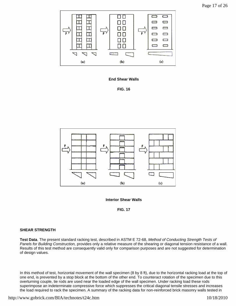
End Shear Walls
FIG. 16
Interior Shear Walls
FIG. 17
SHEAR STRENGTH
Test Data. The present standard racking test, described in ASTM E 72-68, Method of Conducting Strength Tests ofPanels for Building Construction, provides only a relative measure of the shearing or diagonal tension resistance of a wall.Results of this test method are consequently valid only for comparison purposes and are not suggested for determinationof design values.
In this method of test, horizontal movement of the wall specimen (8 by 8 ft), due to the horizontal racking load at the top ofone end, is prevented by a stop block at the bottom of the other end. To counteract rotation of the specimen due to thisoverturning couple, tie rods are used near the loaded edge of the wall specimen. Under racking load these rodssuperimpose an indeterminate compressive force which suppresses the critical diagonal tensile stresses and increasesthe load required to rack the specimen. A summary of the racking data for non-reinforced brick masonry walls tested in
Page 17 of 26
10/18/2010http://www.gobrick.com/BIA/technotes/t24c.htm
accordance with ASTM E 72 is given in Table 3. A typical mode of failure for a 4-in. brick wall subject to racking is shownin Fig. 18.
1Tested in accordance with ASTM E 72.
2Walls not loaded to failure.
3"Structural Properties of Six Masonry Wall Constructions", H. L. Whittemore, A. H. Stang and D. E. Parsons,National Bureau of Standards Report BMS5, 1938.
4"Structural Properties of a Brick Cavity-Wall Construction". H. L. Whittemore. A. H. Stang, D. E. Parsons, NationalBureau of Standards Report BMS23, 1939.
5"SCR brick'* Wall Tests", C. R. Monk, Jr., Structural Clay Products Research Foundation, Research Report No. 1,June 1953.
6"Compressive, Transverse and Racking Strength Tests of Four-Inch Brick Walls", Structural Clay ProductsResearch Foundation, Research Report No. 9, August 1965.
*Reg. U.S. Pat. Off., SCPI
Page 18 of 26
10/18/2010http://www.gobrick.com/BIA/technotes/t24c.htm

Typical Mode of Failure in Racking
FIG. 18
Circular Shear Specimens. Based on experimental work done at the Balcones Research Center of the University of Texasby Professors Neils Thompson and Frank Johnson, the Research Division of the Structural Clay Products Instituteconducted a series of diagonal tensile tests on circular brick masonry specimens. In these tests, a 15-in. diameterspecimen is tested in compression with the line of load at 45 deg to the bed joints. As shown in Fig. 19 the diametricalstresses are largely tensile over the central 80 per cent of the specimen. The tensile stress is approximately constant forabout 60 per cent of the diameter and may be calculated by the following equation:
Stress Distribution in Tensile Splitting Test
Page 19 of 26
10/18/2010http://www.gobrick.com/BIA/technotes/t24c.htm

FIG. 19
where: P = load at rupture, in pounds
D = diameter of specimen, in inches
t = thickness of specimen, in inches
The test results for 133 specimens built with 27 types of brick and type S portland cement-lime mortar of ASTM C 270,Specifications for Mortar for Unit Masonry, are summarized in Table 4. A typical mode of failure for a circular brickspecimen is shown in Fig. 20. While there was no consistent relationship between diagonal tensile strength and brickproperties, such as initial rate of absorption, it appeared that brick with the weakest bond characteristics as shown byflexural strength values also yielded the lowest diagonal tensile strengths.
1"Small Scale Specimen Testing", Progress Report No. 1, SCPI-SCPRF, October 1964.
2All specimens built with type S mortar.
Page 20 of 26
10/18/2010http://www.gobrick.com/BIA/technotes/t24c.htm

Small-Scale Diagonal Tension Test
FIG. 20
The test results for 20 circular specimens built with one type of brick and four types of mortars are summarized in Table 5.As indicated, the mortar type had a marked effect on the diagonal tensile strength of circular back masonry specimens.
1"Small Scale Specimen Testing", Progress Report No. 1. SCPI-SCPRF, October 1964.
2C = portland cement; L = hydrated lime (type S); S = sand.
328-day briquets.
4All specimens built with 3/8-in. joints and brick having an average compressive strength of 11,771 psi and an initial rate of absorption of 10.6 g per minper 30 sq in.
Square Shear Specimens. The Brick Institute of America has continued to study the diagonal tensile or shear strength ofbrick masonry in an effort to develop both test methods and design information. Working with the National Bureau ofStandards and the Research Division of John A. Blume and Associates (San Francisco), a test method has beendeveloped that has several advantages over the ASTM E 72 racking test procedure. As previously stated, in the E 72procedure the hold-down tie rods required to prevent overturning of the specimen under load produce an indeterminatebearing condition at the bottom edge of the specimen, thus preventing an analytic determination of the stress within thewall specimen itself.
Page 21 of 26
10/18/2010http://www.gobrick.com/BIA/technotes/t24c.htm

In the alternate test procedure, which will be submitted to ASTM as a proposed alternate to the ASTM E 72 procedure,the specimens are nominally 4 ft by 4 ft as opposed to the 8-ft square specimen in the E 72 procedure. In this method, thetest results are susceptible to stress analysis. In addition, they are more reproducible and thus more reliable forcomparison and design data purposes.
The square specimen is placed in the testing frame so as to be loaded in compression along a diagonal, thus producing adiagonal tension failure with the specimen splitting apart along the loaded diagonal (see Figs. 21 and 22). The results ofboth small scale (2 ft square) and full scale (4 ft square) tests of 4, 6 and 8-in. thick brick masonry specimens aresummarized in Table 6 and typical shear stress-strain curies are displayed in Fig. 23. All specimens were constructedwith type S mortar. The shearing stress V'm is determined by the equation
where: F = diagonal compressive force or load, in pounds
t = thickness of wall specimen, in inches
l = length of a side of a square specimen, in inches
Wallette Shear Test Setup
FIG. 21
Page 22 of 26
10/18/2010http://www.gobrick.com/BIA/technotes/t24c.htm
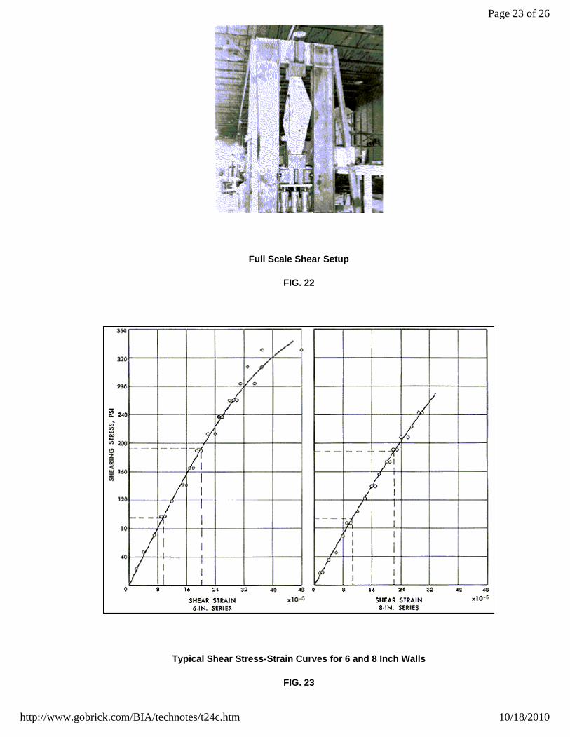
Full Scale Shear Setup
FIG. 22
Typical Shear Stress-Strain Curves for 6 and 8 Inch Walls
FIG. 23
Page 23 of 26
10/18/2010http://www.gobrick.com/BIA/technotes/t24c.htm

12 ft square.
24 ft square.
Effects of Normal Loads. The Brick Institute of America has also investigated the effects of compressive loads normal tothe bed joints on the shearing strength of plain (non-reinforced) brick masonry walls. Table 7 summarizes the results ofthese tests with the normal compressive load on the wall varying from 0 (unloaded) to 375 psi. The specimens were builtwith one type of brick utilizing type S mortar and inspected workmanship. All specimens were two wythes, 8 in. inthickness and bonded with metal ties.
1Built with type S mortar, inspected workmanship and metal-tied.
fb = 11,100 psi
Page 24 of 26
10/18/2010http://www.gobrick.com/BIA/technotes/t24c.htm

IRA = 20.7 g/min/30 in2
Allowable Stresses. The allowable shear stresses for non-reinforced masonry provided in the 1969 SCPI Standard,Building Code Requirements for Engineered Brick Masonry, are shown in Table 8, and for reinforced masonry in Table 9.
The Standard also provides a basis for the design of biaxially loaded shear walls. Section 4.7.12.1 states:
"In non-reinforced shear walls, the virtual eccentricity (el) about the principal axis which is normal to the length (l) of theshear wall shall not exceed an amount which will produce tension. In non-reinforced shear walls subject to bending aboutboth principal axes, (etl + elt) shall not exceed (tl / 3) where et = virtual eccentricity about the principal axis which is normalto the thickness (t) of the shear wall. Where the virtual eccentricity exceeds the values given in this section, shear wallsshall be designed in accordance with Section 4.7.9 or 4.7.11". (Reinforced or partially reinforced walls.)
Provision is also made in the standard for increasing the shear capacity of the wall by taking into considerationcompressive loads on the wall. Section 4.7.12.3 states:
"The allowable shearing stresses in non-reinforced and reinforced shear walls shall be taken as the allowable stressesgiven in Tables 3 and 4 (Tables 8 and 9 of this Technical Notes) ,respectively, plus one fifth of the average compressivestress due to dead load at the level being analyzed. In no case, however, shall the allowable shear stresses exceed themaximum values given in Tables 3 and 4.
"In computing the shear resistance of the wall, only the web shall be considered."
Page 25 of 26
10/18/2010http://www.gobrick.com/BIA/technotes/t24c.htm

REFERENCES
1. Technical Notes on Brick Construction, BIA, (a monthly series).
2. Gross, J. G.; Dikkers, R. D.; and Grogan, J. C.; Recommended Practice for Engineered Brick Masonry, SCPI,November 1969.
3. Allen M. H. and Watstein, D.; Compressive, Transverse and Shear Strength Tests of Six and Eight-lnch Single-Wythe Walls Built with Solid and Heavy-Duty Hollow Clay Masonry Units, Research Report No. 16, SCPI,September 1969.
4. Blume, J. A. and Prolux, J.; Shear in Grouted Brick Masonry Wall Elements, Western States Clay ProductsAssociation, August 1968.
Page 26 of 26
10/18/2010http://www.gobrick.com/BIA/technotes/t24c.htm