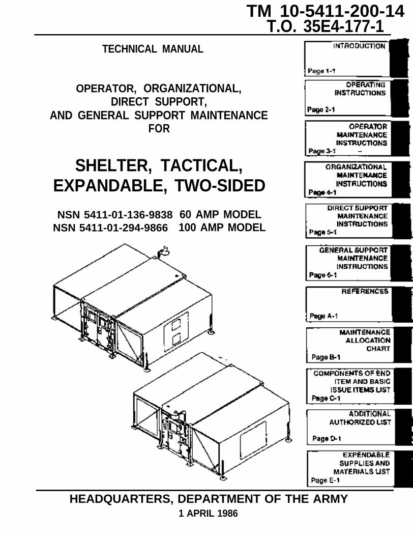
page 3-1 shelter, tactical, expandable, two … 2-sided tm 10-5411-2… · · 2013-02-21shelter,...
TRANSCRIPT
Page E-1
Page D-1
Page C-1
Page B-1
Page A-1
Page 6-1
Page 5-1
Page 4-1
Page 3-1
Page 2-1
Page 1-1
TM 10-5411-200-14T.O. 35E4-177-1
TECHNICAL MANUAL
OPERATOR, ORGANIZATIONAL,DIRECT SUPPORT,
AND GENERAL SUPPORT MAINTENANCEFOR
SHELTER, TACTICAL,EXPANDABLE, TWO-SIDED
NSN 5411-01-136-9838NSN 5411-01-294-9866
60 AMP MODEL100 AMP MODEL
HEADQUARTERS, DEPARTMENT OF THE ARMY1 APRIL 1986

TM 10-5411-200-14T.O. 35E4-177-1
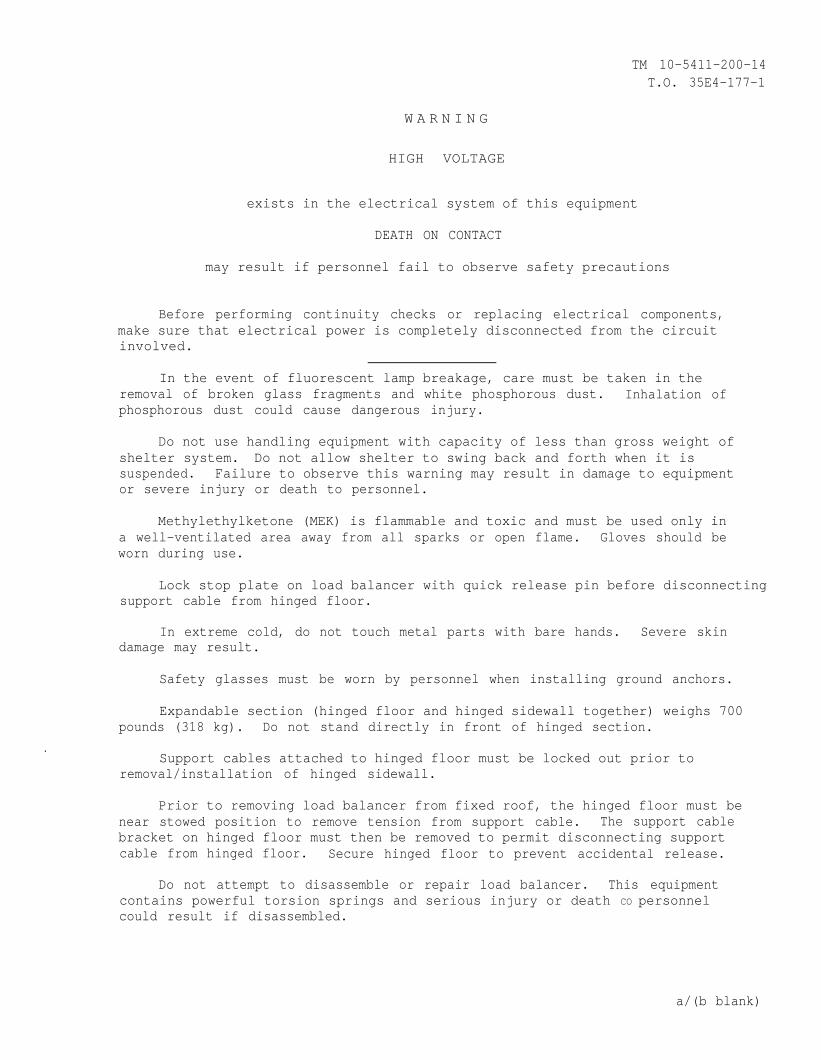
W A R N I N G
HIGH VOLTAGE
exists in the electrical system of this equipment
DEATH ON CONTACT
may result if personnel fail to observe safety precautions
Before performing continuity checks or replacing electrical components,make sure that electrical power is completely disconnected from the circuitinvolved.
In the event of fluorescent lamp breakage, care must be taken in theremoval of broken glass fragments and white phosphorous dust. Inhalation ofphosphorous dust could cause dangerous injury.
Do not use handling equipment with capacity of less than gross weight ofshelter system. Do not allow shelter to swing back and forth when it issuspended. Failure to observe this warning may result in damage to equipmentor severe injury or death to personnel.
Methylethylketone (MEK) is flammable and toxic and must be used only ina well-ventilated area away from all sparks or open flame. Gloves should beworn during use.
Lock stop plate on load balancer with quick release pin before disconnectingsupport cable from hinged floor.
In extreme cold, do not touch metal parts with bare hands. Severe skindamage may result.
Safety glasses must be worn by personnel when installing ground anchors.
Expandable section (hinged floor and hinged sidewall together) weighs 700pounds (318 kg). Do not stand directly in front of hinged section.
.Support cables attached to hinged floor must be locked out prior to
removal/installation of hinged sidewall.
Prior to removing load balancer from fixed roof, the hinged floor must benear stowed position to remove tension from support cable. The support cablebracket on hinged floor must then be removed to permit disconnecting supportcable from hinged floor. Secure hinged floor to prevent accidental release.
Do not attempt to disassemble or repair load balancer. This equipmentcontains powerful torsion springs and serious injury or death CO personnelcould result if disassembled.
a/(b blank)

TM 10-5411-200-14 T.O. 35E4-177-1
CHANGE NO. 9 HEADQUARTERS, DEPARTMENT OF THE ARMY
AND THE AIR FORCE WASHINGTON, DC, 31 AUGUST 2005
TECHNICAL MANUAL
OPERATOR, ORGANIZATIONAL, DIRECT SUPPORT AND GENERAL SUPPORT MAINTENANCE
FOR SHELTER, TACTICAL, EXPANDABLE, TWO-SIDED
NSN: 5411-01-136-9838 NSN: 5411-01-294-9866
DISTRIBUTION STATEMENT A: Approved for public release; distribution is unlimited. TM 10-5411-200-14, 1 April 1986, is updated as follows: 1. File this sheet in front of the manual for reference. 2. This change implements Army Maintenance Transformation and changes the
Maintenance Allocation Chart (MAC) to support Field and Sustainment Maintenance.
3. New or updated change information is indicated by a vertical bar in the outer
margin of the page. 4. Remove old pages and insert new pages as indicated below:
Remove Pages Insert Pages A/(B Blank) B-1 through B-11/(B-12 Blank) B-1 through B-12 Electronic 2028 Instructions Electronic 2028 Instructions/ Blank DA Form 2028 2028 Sample Front/Back 2028 Front/2028 Back 2028 Front/2028 Back

ARMY TM 10-5411-200-14 C-9
By Order of the Secretary of the Army:
PETER J. SCHOOMAKER General, United States Army Chief of Staff
Official:
SANDRA R. RILEY Administrative Assistant to the Secretary of the Army 0521009
MICHAEL E. RYAN GENERAL, USAF Chief of Staff
Official: GEORGE T. BABBETT General, USAF Commander, Air Force Materiel Command
Distribution: To be distributed in accordance with initial distribution number (IDN) 252533 requirements for TM 10-5411-200-14.
CHANGE
NO. 8
ARMY TM 10-5411-200-14AIR FORCE T.O. 35E4-177-1
C8
HEADQUARTERS DEPARTMENTS OFTHE ARMY AND THE AIR FORCE
WASHINGTON, D.C., 20 JANUARY 1997
Operator, Organizational, Direct Support, and General SupportMaintenance Manual
SHELTER, TACTICAL, EXPANDABLE, TWO-SIDEDNSN 5411-01-136-9838 (60 AMP MODEL)NSN 5411-01-294-9866 (100 AMP MODEL)
DISTRIBUTION STATEMENT A: Approved for public release; distribution is unlimited
TM 10-5411-200-14/ T.O. 35E4-177-1,1 April 1986, is changed as follows:
1. The Cover is changed to add the 100 Amp Model.
2. Remove and insert pages as indicated below. New or changed text material is indicated by avertical barin the margin. An illustration change is indicated by a miniature pointing hand.
Remove pages2-1 and 2-22-3 and 2-42-17 and 2-182- 8.1/ (2-18.2 blank)4-23 through 4-264-39 through 4-464-179 and 4-160
4-181 and 4-182
4-185 and 4-186
C-5/ (C-6 blank)E-31 (E-4 blank)Cover
Insert pages2-1 and 2-22-3 and 2-42-17 and 2-182-18.1 through 2-18.3 (2-18.4 blank)4-23 through 4-264-39 through 4-464-179 and 4-1804-180.1 and 4-180.24-181 and 4-1824-182.1 (4-182.2 blank)4-185 and 4-1864-186.1/ (4-186.2 blank)C-5/ (C-6 blank)E-3/ (E-4 blank)Cover
3. Retain this sheet in front of manual for reference purposes.
ARMY TM 10-5411-200-14AIR FORCE T.O.35E4-177-1
C8
By Order the Secretaries of the Army and Air Force:
General, United States ArmyChief of Staff
Administrative Assistant to theSecretary of the Army
03151
RONALD R. FOGELMANGeneral, USAFChief of Staff
HENRY VICCELLIO, JR.General, USAFCommander, Air Force Materiel Command
DISTRIBUTION:To be distributed in accordance with DA Form 12-25-E, block no. 2533, requirements for
TM 10-5411-200-14.
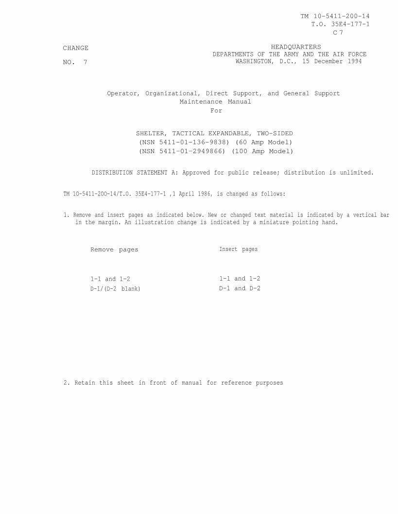
CHANGE
NO. 7
TM 10-5411-200-14T.O. 35E4-177-1
C 7
HEADQUARTERSDEPARTMENTS OF THE ARMY AND THE AIR FORCE
WASHINGTON, D.C., 15 December 1994
Operator, Organizational, Direct Support, and General SupportMaintenance Manual
For
SHELTER, TACTICAL EXPANDABLE, TWO-SIDED(NSN 5411-01-136-9838) (60 Amp Model)(NSN 5411-01-2949866) (100 Amp Model)
DISTRIBUTION STATEMENT A: Approved for public release; distribution is unlimited.
TM 1O-5411-2OO-14/T.O. 35E4-177-1 ,1 April 1986, is changed as follows:
1. Remove and insert pages as indicated below. New or changed text material is indicated by a vertical barin the margin. An illustration change is indicated by a miniature pointing hand.
Remove pages Insert pages
1-1 and 1-2 1-1 and 1-2D-1/(D-2 blank) D-1 and D-2
2. Retain this sheet in front of manual for reference purposes
TM 10-5411-200-14T.O. 35E4-177-1
C 7
By Order of the Secretarles of the Army and Air Force:
Official:
MILTON H. HAMILTONAdministtative Assistant to the
Secretary of the Army0766
GORDON R. SULLIVANGeneral, United States Army
Chief of Staff
MERRILL A. McPEAKGeneral, USAFChief of Sfaff
RONALD W. YATESGeneral, USAFCommander Air Force Materiel Command
DISTRIBUTION:To be distributed in accordance with DA Form 12-25-E, block no. 2533, requirements for
TM 10-5411-200-14.
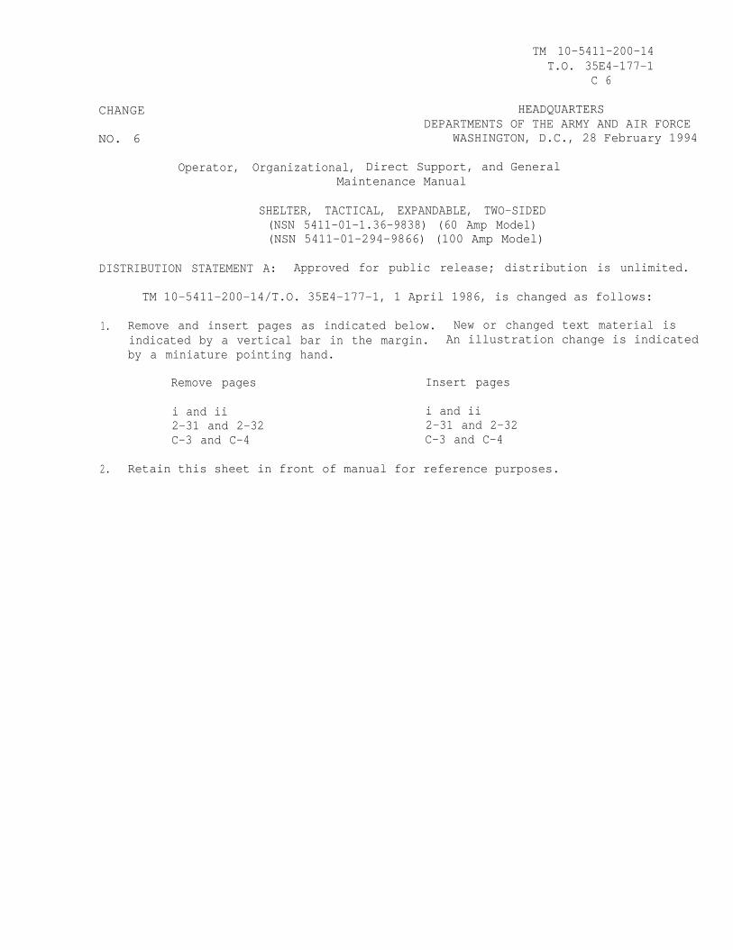
CHANGE
NO. 6
TM 10-5411-200-14T.O. 35E4-177-1
C 6
HEADQUARTERSDEPARTMENTS OF THE ARMY AND AIR FORCE
WASHINGTON, D.C., 28 February 1994
Operator, Organizational, Direct Support, and GeneralMaintenance Manual
SHELTER, TACTICAL, EXPANDABLE, TWO-SIDED(NSN 5411-01-1.36-9838) (60 Amp Model)(NSN 5411-01-294-9866) (100 Amp Model)
DISTRIBUTION STATEMENT A: Approved for public release; distribution is unlimited.
TM 10-5411-200-14/T.O. 35E4-177-1, 1 April 1986, is changed as follows:
1. Remove and insert pages as indicated below. New or changed text material isindicated by a vertical bar in the margin. An illustration change is indicatedby a miniature pointing hand.
Remove pages Insert pages
i and ii i and ii2-31 and 2-32 2-31 and 2-32C-3 and C-4 C-3 and C-4
2. Retain this sheet in front of manual for reference purposes.
TM 10-5411-200-14T.O. 35E4-177-1
C-6
By Order of the Secretaries of the Army and Air Force:
Official:
GORDON R. SULLIVANGeneral, United States Army
Chief of Staff
MILTON H. HAMILTONAdministrative Assistant to the
Secretary of the Army06256
MERRILL A. McPEAKGeneral, USAFChief of Staff
Official:
RONALD W. YATESGeneral, USAFCommander Air Force Materiel Command
DISTRIBUTION:To be distributed in accordance with DA Form 12-25-E, block no. 2533, requirements for
TM 10-5411-200-14.
CHANGE
NO. 5
Operator, Organizational, DirectMaintenance
TM 10-5411-200-14T.O. 35E4-177-1
C 5
HEADQUARTERSDEPARTMENTS OF THE ARMY AND AIR FORCE
WASHINGTON, D.C., 30 JULY 1993
Support, and General SupportManual
SHELTER, TACTICAL, EXPANDABLE, TWO-SIDED(NSN 5411-01-136-9838) (60 Amp Model)(NSN 5411-01-294-9866) (100 Amp Model)
DISTRIBUTION STATEMENT A: Approved for public release; distribution is unlimited.
TM 10-5411-200-14/T.O. 35E4-177-1, 1 April 1986, is changed as follows:
1. Remove and insert pagesindicated by a verticalby a miniature pointing
Remove pages
4-934-99
2. Retain this
as indicated below. New or changed text material isbar in the margin. An illustration change is indicatedhand.
Insert pages
through 4-96 4-93 through 4-96through 4-108 4-99 through 4-108
sheet in front of manual for reference purposes.
TM 10-5411-200-14T.O. 35E4-177-1
By Order of the Secretaries of the Army and Air Force:
Official:
GORDON R. SULLIVANGeneral, United States Army
Chief of Staff
MILTON H. HAMILTONAdministrative Assistant to the
Secretary of the Army04990
MERRILL A. McPEAKGeneral, USAFChief of Staff
official:
RONALD W. YATESGeneral, USAFCommander Air Force Materiel Command
DISTRIBUTION:To be distributed in accordance with DA Form 12–25-E, block no. 2533, requirements for
TM 10–5411 –200-14.
ARMY TM 10-5411-200-14AIR FORCE T.O. 35E4-177-1
C 4
CHANGE HEADQUARTERS,DEPARTMENTS OF THE ARMY AND AIR FORCE
NO. 4 WASHINGTON, D.C. 30 April 1993
Operator, Organizational, Direct Support, and General SupportMaintenance Manual
SHELTER, TACTICAL, EXPANDABLE, TWO-SIDED
DISTRIBUTION STATEMENT
TM 10-5411-200-14/T.O.
NSN 5411-01-136-9838 (60 AMP MODEL)NSN 5411-01-294-9866 (1OO AMP MODEL)
A: Approved for public release; distribution is unlimited.
35E4-177-1, 1 April 1986 is changed as follows:
1. Remove and insert pages as indicated below. New or changed text material isindicated by a vertical bar in the margin. An illustration change is indicatedby a miniature pointing hand.
Remove pages Insert pages
4-171 and 4-172 4-171 and 4-172D-1/(D-2 blank) D-1/(D-2 blank)E-1 through E-3/(E-4 blank) E-1 through E-3/(E-4 blank)
2. Retain this sheet in front of manual for reference purposes.
ARMY TM 10-5411-200-14AIR FORCE T.O. 35E4-177-1
By Order of the Secretaries of the Army and Air Force:
Official:
GORDON R. SULLIVANGeneral, United States Army
Chief of Staff
MILTON H. HAMILTONAdministrative Assistant to the
Secretary of the Army04078
MERRILL A. McPEAKGeneral, USAFChief of Staff
Official:
RONALD W. YATESGeneral, USAFCommander, Air Force Materiel Command
DISTRIBUTION:To be distributed in accordance with DA Form 12-25-E, block no. 2533, requirements for
TM 10-5411 -200-14..

CHANGE
NO. 3
ARMY TM 10-5411-200-14AIR FORCE T. O. 35E4-177-1
C 3
HEADQuARTERS,DEPARTMENTS OF THE ARMY AND AIR FORCE
WASHINGTON, D.C., 23 May 1991
Operator, Organizational, Direct Support and General SupportMaintenance Manual
SHELTER, TACTICAL, EXPANDABLE, TWO-SIDEDNSN 5411-01-1369838 (60 AMP MODEL)NSN 541141-294-9866 (100 AMP MODEL)
Approved for public release; distribution is unlimited
TM 10-5411–200-14/T. O. 35E4-177-1, 1 April 1986 is changed as follows:
1. Remove and insert pages as indicated below. New or changed text material is indicated by a vertical bar inthe margin. An illustration change is indicated by a miniature pointing hand.
Remove pages Insert pages
1-1 and 1–2 1-1 and 1–21-5 and 1-6 1-5 and 1-6C–3 and C-4 C–3 and C-4
2. Retain this sheet in front of manual for reference purposes.
By Order of the Secretaries of the Amy and Air Force:
CARL E. VUONOGeneral, United States Army
Chief of Staff
Official:PATRICIA P. HICKERSONColonel, United States Army
The Adjutant General
MERRILL A. McPEAKGeneral USAFChief of Staff
Official:CHARLES C. McDONALD
General, USAFCommander, Air Force Logistics Command
DISTRIBUTION:To be distributed in accordance with DA Form 12-25E, (qty rqr block no. 2533).

TM 10-5411-200-14T.O. 35E4-177-1
CHANGE
No. 2
HEADQUARTERS, DEPARTMENTS OFTHE ARMY AND THE AIR FORCE
WASHINGTON, D.C. ,14 February 1990
Operator, Organizational, Direct Support,And General Support Maintenance
SHELTER, TACTICAL, EXPANDABLE, TWO-SIDED(NSN 5411-01-136-9838) (60 Amp Model)(NSN 5411-01-294-9866) (100 Amp Model)
Approved for public release; Distribution is unlimited.
TM 10-5411-200-14/T.O. 35E4-177-1, 1 April 1986, is changed as follows:
1. Title is changed as shown above.
2. Remove and insert pages as indicated below. New or changed text materialis indicated by a vertical bar in the margin. An illustration change is indicatedby a miniature pointing hand.
Remove pages Insert pages
i and ii1-1 through 1-62-1 and 2-22-9 through 2-142-17 and 2-18---2-21 through 2-24----2-29 and 2-303-7 and 3-84-.5 through 4-12---4-13 and 4-144-27 through 4-364-47 through 4-54---4-55 and 4-564-179 through 4-186---5-5 through 5-8A-1/A-2D-1/D-2E-1 and E-2---Index 1 through Index 4
i and ii1-1 through 1-62-1 and 2-22-9 through 2-142-17 and 2-182-18.1/2-18.22-21 through 2-242-24.1/2-24.22-29 and 2-303-7 and 3-84-5 through 4-124-12.1 and 4-12.24-13 and 4-144-27 through 4-364-47 through 4-544-54.1 and 4-54.24-55 and 4-564-179 through 4-1864-187 through 4-1905-5 through 5-8A-1/A-2D-1/D-2E-1 and E-2E-3/E-4Index 1 through Index 4
TM 10-5411-200-14T.O. 35E4-177-1
C 2
3. Retain this sheet in front of manual for reference purposes.
By Order of the Secretaries of the Army and the Air Force:
CARL E. VUON06eneral, United States Amy
Chief of Staff
Official:WILLIAM J. MEEHAN, II
Brigadier 6eneral, United States ArmyThe Adjutant 6eneral
LARRY D. WELCH, 6eneral USAFChief of Staff
Official:ALFRED G. HANSEN
General, USAF, Commander, Air ForceLogistics Command
DISTRIBUTION:To be distributed in accordance with DA 12-25A, Operator, Unit, Direct Support
and General Support Maintenance requirements for Shelter, Expandable, 2-Side(5-4-3118-2).
CHANGE
No. 1
TM 10-5411-200-14T.O. 35W4-177-1
C 1
HEADQUARTERSDEPARTMENTS OF THE ARMY AND AIR FORCE
WASHINGTON, D.C., 8 June 1989
Operator, Organizational, Direct Supportand General Support Maintenance
SHELTER, TACTICAL, EXPANDABLE, TWO-SIDED(NSN 5411-01-136-9838)
Approved for public release. Distribution is unlimited.
TM 10-5411-200-14/T.O. 35E4-177-1, 1 April 1986, is changed as follows:
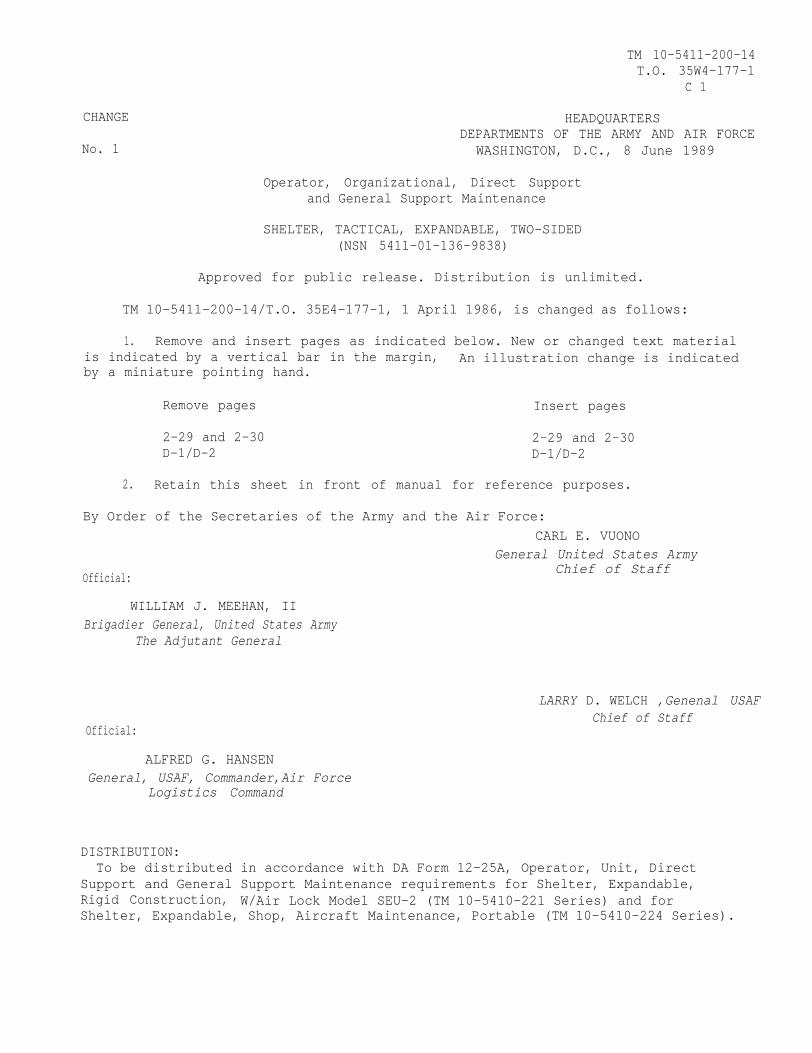
1. Remove and insert pages as indicated below. New or changed text materialis indicated by a vertical bar in the margin, An illustration change is indicatedby a miniature pointing hand.
Remove pages Insert pages
2-29 and 2-30 2-29 and 2-30D-1/D-2 D-1/D-2
2. Retain this sheet in front of manual for reference purposes.
By Order of the Secretaries of the Army and the Air Force:CARL E. VUONO
General United States Army
Official:
WILLIAM J. MEEHAN, IIBrigadier General, United States Army
The Adjutant General
Official:
ALFRED G. HANSENGeneral, USAF, Commander,Air Force
Logistics Command
Chief of Staff
LARRY D. WELCH ,Genenal USAFChief of Staff
DISTRIBUTION:To be distributed in accordance with DA Form 12-25A, Operator, Unit, Direct
Support and General Support Maintenance requirements for Shelter, Expandable,Rigid Construction, W/Air Lock Model SEU-2 (TM 10-5410-221 Series) and forShelter, Expandable, Shop, Aircraft Maintenance, Portable (TM 10-5410-224 Series).
TM 10-5411-200-14 T.O. 35E4-177-1
INSERT LATEST CHANGED PAGES. DESTROY SUPERSEDED PAGES.
A/(B Blank) Change 9 USA
LIST OF EFFECTIVE PAGES
NOTE: The portion of text affected by the update is indicated by a vertical line in the outer margins of the
page. Updates to illustrations are indicated by shaded or screened areas, or by miniature pointing hands. Zero in the “Change No.” column indicates an original page or work package.
Dates of issue for original and changed pages / work packages are: Original .. 0 .. 1 April 1986 Change .. 5 .. 30 July 1993 Change .. 1 .. 8 June 1989 Change .. 6 .. 28 February 1994 Change .. 2 .. 14 February 1990 Change .. 7 .. 15 December 1994 Change .. 3 .. 23 May 1991 Change .. 8 .. 20 January 1997 Change .. 4 .. 30 April 1993 Change .. 9 .. 31 August 2005
TOTAL NUMBER OF PAGES FOR THIS PUBLICATION IS 350, CONSISTING OF THE FOLLOWING:
Page No.
Change No.
Page No.
Change No.
Page No.
Change No.
Page No.
Change No.
Cover 0 2-15 through 2-17 0 4-26 8 5-5 2
a/(b Blank) 0 2-18 through 2-18.3/(2-18.4 Blank) 8 4-27 0 5-6 0
i 6 2-19 through 2-21 0 4-28 through 4-36 2 5-7 2
ii 2 2-22 2 4-37 through 4-39 0 5-8 through 5-14 0
1-0 0 2-23 0 4-40 through 4-45 8 6-1 through 6-4 0
1-1 2 2-24 through 2-24.1/(2-24.2 Blank) 2 4-46 0 A-1/(A-2 blank) 2
1-2 7 2-25 through 2-28 0 4-47 through 4-55 2 B-1 through B-12 9
1-3 2 2-29 through 2-30 2 4-56 through 4-92 0 C-1 through C-3 0
1-4 0 2-31 6 4-93 through 4-95 5 C-4 6
1-5 3 2-32 through 2-36 0 4-96 through 4-99 0 C-5/(C-6 blank) 8
1-6 2 3-1 through 3-7 0 4-100 through 4-108 5 D-1 through D-2 7
2-1 8 3-8 2 4-109 through 4-179 0 E-1 0
2-2 2 3-9 through 3-15/(3-16 Blank) 0 4-180 through
4-182.1/(4-182.2 Blank) 8 E-2 4
2-3 8 4-1 through 4-4 0 4-183 2 E-3/(E-4 blank) 8
2-4 through 2-8 0 4-5 through 4-13 2 4-184 through 4-185 0 Index-1 2
2-9 through 2-12 2 4-14 through 4-22 0 4-186 through 4-186.1/(4-186.2 Blank) 8 Index-2 0
2-13 0 4-23 through 4-24 8 4-187 through 4-190 2 Index-3 through Index-4 2
2-14 2 4-25 0 5-1 through 5-4 0 Back Cover 0

TM 10-5411-200-14T.O. 35E4-177-1
TECHNICAL MANUAL HEADQUARTERS, DEPARTMENTS OFTHE ARMY AND THE AIR FORCE
NO. 10-5411-200-14 WASHINGTON, D.C., 1 April 1986
OPERATOR, ORGANIZATIONAL, DIRECT SUPPORT,AND GENERAL SUPPORT MAINTENANCE
SHELTER, TACTICAL, EXPANDABLE, TWO-SIDED(NSN 5411-01-136-9838)(60 Amp Model)(NSN 5411-01-294-9866)(100 Amp Model)
DISTRIBUTION STATEMENT A: Approved for public release; distribution is unlimited
L
REPORTING ERRORS AND RECOMMENDING IMPROVEMENTS
You can help improve this manual. If you find any mistakes or if you know ofa way to improve the procedures, please let us know. Reports shall be sub-mitted as follows: A reply will be furnished to you.
(A) Army - DA Form 2028 (Recommended Changes to Publications and BlankForms), or DA Form 2028-2 located in the back of this manual direct to:Commander, U.S. Army Aviation and Troop Command, ATTN: AMSAT-I-MP, 4300Goodfellow Boulevard, St. Louis, MO 63120-1798.
(F) Air Force - AFTO Form 22 directly to: Commander, Sacramento AirLogistics Center, ATTN: MMST, McClellan Air Force Base, CA 95652 inaccordance with TO-00-5-1,
CHAPTER 1Section I.Section II.
1-11-11-3
CHAPTER 2Section I.
Section II.
Section III.Section IV.Section V.
CHAPTER 3Section I.Section II.
TABLE OF CONTENTS
Page
INTRODUCTIONGeneral InformationEquipment Description and Data
OPERATING INSTRUCTIONSDescription and Use of Operator’s Controls and
IndicatorsOperator’s Preventive Maintenance Checks andServices (PMCS)
Service Upon Receipt of ShelterOperation Under Usual ConditionsOperation Under Unusual Conditions
OPERATOR MAINTENANCE INSTRUCTIONSTroubleshooting ProceduresOperator Maintenance Procedures
2-1
2-1
2-42-112-322-33
3-13-13-4
Change 6 i
TM 10-5411-200-14T.O. 35E4-177-1
TABLE OF CONTENTS (cont)
CHAPTER 4 ORGANIZATIONAL MAINTENANCE INSTRUCTIONSSection I Repair Parts, ,Special Tools, TMDE, and Support
EquipmentSection II. Troubleshooting ProceduresSection III. Organizational Maintenance Procedures Section IV. Preparation for Storage and Shipment
CHAPTER 5 DIRECT SUPPORT MAINTENANCE INSTRUCTIONS
CHAPTER 6 GENERAL SUPPORT MAINTENANCE INSTRUCTIONS
APPENDIX A REFERENCES
APPENDIX B MAINTENANCE ALLOCATION CHART
APPENDIX C COMPONENTS OF END ITEM AND BASIC ISSUE ITEMSLIST
APPENDIX D ADDITIONAL AUTHORIZED LIST
APPENDIX E EXPENDABLE SUPPLIES AND MATERIALS LIST
ALPHABETICAL INDEX
Page
4-1
4-14-24-54-190
5-1
6-1
A-1
B-1
C-1
D-1
E-1
INDEX-1
ii CHANGE 2
TM 10-5411-200-14T.O. 35E4-177-1
EXPANDED SHELTER
Full External View of Two-Sided Expandable Tactical Shelter
1-0

TM 10-5411-200-14T.O. 35E4-177-1
CHAPTER 1
INTRODUCTION
Section 1. GENERAL INFORMATION
1-1. SCOPE. This manual is for use by personnel responsible for operation and maintenance of thetwo-sided expandable tactical shelter assembly, which will be referred to as the shelter. It provides theuser with necessary instructions to use the shelter and to perform required maintenance in accordancewith the Maintenance Allocation Chart in Appendix B.
NOTE
Some portions of this publication are not applicable to all services. Theseportions are prefixed to indicate the services to which they pertain (A)for Army, (F) for Air Force, and (N) for Navy. Portions not prefixedare applicable to all services.
1-2. MAINTENANCE FORMS, RECORDS, AND REPORTS. Maintenance forms. records, and reportsused by:
a. (A) Are prescribed by DA PAM 736-750, the Army Maintenance Management System(TAMMS).
b. (F) Are prescribed in AFM-66-1 and the applicable 00-20 Series Technical Orders.
c. (N) Refer to their service peculiar directives to dtermine applicable maintenance forms andrecords to be used.
d. (A) Users shall refer to the Maintenance Allocation Chart (MAC) for task and levels ofmaintenance to be performed. Where the density of equipment is not sufficient to authorize unitpersonnel with skills necessary to perform unit-level maintenance functions, AR 750-1, paragraph 2-8cstates, “Unserviceable reparable, (properly preserved, protected, and tagged) that are beyond theauthorized capability or capacity to repair, will be evacuated through the appropriate SUPPLY supportactivities for repair or exchange.” For units authorized personnel with skills to perform greater thanunit-level maintenance functions, AR 750-1, paragaph 2-9b states, "DS and GS units may grant authorityto supported units to perform the next higher level repair, if the supported unit has the capability andcapacity to perform the repair.”
(F) Users shall accomplish maintenance at the user level consistent with their capability inaccordance with policies established in AFM 66-1.
f. (N) Users shall determine their maintenance levels in accordance with their service directives.
1-3. (A) DESTRUCTION OF MATERIEL TO PREVENT ENEMY USE. For destruction procedures. for materiel refer to TM 750-244-3.
14. ADMINISTRATIVE STORAGE. For procedures and inspections required during administrativestorage, refer to Chapter 4, paragraph 4-44.
Change 2 1-1

TM 10-5411-200-14T.O. 35E4-177-1
1-5. (A) REPORTING EQUIPMENT IMPROVEMENT RECOMMENDATIONS (EIR’S). If your shelterneeds improvement, let us know. Send us an EIR. You, the user, are the only one who can tell us what youdon’t like about your equipment. Let us know why you don’t like the design. Tell us why a procedure is hardto perform. Put it on an SF 368 (Quality Deficiency Report). Mail it to: Commander, U. S. Army Aviationand Troop command ATTN: AMSAT-I-MDO, 4300 Goodfellow Boulevard, St. Louis, Missouri, 63120-1798.We’ll send you a reply.
1-6. LIST OF ABBREVIATIONS.
AC
cm
ECU
EIR
ft
Hz
in.
IS0
kg
lb pound
lg
MAC
MEK
m m
MTOE
No.
PMCS
ref
sq
TMDE
W C
Air conditioner
centimeter
Environmental Control Unit
Equipment Improvement Report
foot (feet)
Hertz
inch
International standards Organization
Kilogram
long
Maintenance Allocation chart
Methylethylketone (Solvent)
millimeter
Modified Table of Organization and Equipment
number
Preventive Maintenance Checks and Services
reference
square
Test, Measurement and Diagnostic Equipment
Volts, alternating current
1-2 Change 7
TM 10-5411-200-14T.O. 35E4-177-1
Section II. EQUIPMENT DESCRIPTION AND DATA
1-7. PURPOSE OF TWO-SIDED EXPANDABLE TACTICAL SHELTER ASSEMBLY. A self-contained transportable multi-application utility shelter. A member of familyof standard rigid wall ISO shelters to be used by branches of the Department ofDefense.
Capabilities and Features:
● Equipped with standard ISO fittings for easy transportability.
● Provided with mobilizer fittings for mobilizer transportation.
● Built-in fork lift provisions.
● All weather operation.
● Environmentally controlled interior.
● Rigid wall construction.
● Simple and fast deployment.
● Designed to operate under blackout conditions with door activated blackoutswitch.
● External electrical power connection.
● Easy to maintain.
Differences Between Models:
● The early model Shelter, Tactical, Expandable, Two-Sided (NSN 5411-01-138-9838), provides overload protection through a 60 amp or 100 amp Model NQOBcircuit breaker panel, manufactured by Square D Company. When replacementof the circuit breaker panel is necessary, the replacement will be ModelNQOD circuit breaker panel, which is also manufactured by Square D Companyand has the capability to accommodate either 60 amp or 100 amp service.Model NQOD is two inches shorter in length than the earlier Model NQOB,and modifications to the shelters are required when replacement isnecessary (see paragraph 4-7.1).
NOTE
All electrical components (circuit breakers, switches, andwiring) used in the earlier model circuit breaker panel arecompatible with the new Model NQOD.
● The late model Shelters, Tactical, Expandable, Two-Sided (NSN 5411-01-294-9866) are initially equipped with the new Model NQOD circuit breaker panelwhen placed into service.
cHANGE 2 1-3
TM 10-5411-200-14T.O. 35E4-177-1
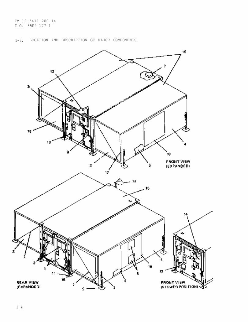
1-8. LOCATION AND DESCRIPTION OF MAJOR COMPONENTS.
1-4
TM 10-5411-200-14T.O. 35E4-177-1
1-8. (cont)
1.
2.
3.
4.
5.
6.
7.
8.
9.
10.
11.
12.
13.
14.
15.
W A R N I N G
LEFT AND RIGHT CARGO DOORS, Provides access to shelter for delivery of bulky materiel and equipment.
Door vents are spring loaded to swing upward. To preventinjury, hold door vent shut while unlatching all the retainingclips.
DOOR VENTS. Manually operated vents provide ventilation and pressure equalization for the shelter.
HINGED ENDWALLS. Hinged to center structure and swing out to form walls in the expandable section ofshelter.
HINGED SIDEWALL. Hinged to hinged floor panel. Forms a wall in the expandable section when shelter isexpanded.
LEVELING JACKS. Secured to hinged floor and hinged sidewall. Provides leveling means for the expandablesection.
HINGED FLOOR PANEL. Hinged to fixed floor panel. Provides additional floor space when shelter is expanded.
EXPANDABLE SIDE LOAD BALANCER. Consists of cable reels, cable guides, and support cable to assist inexpanding and closing of hinged floor panel and hinged sidewall.
ECU PANELS. Provides for connections of ECU equipment used with shelter
Shelter grounding is not optional on shelters used forDeployable Medical Systems (DEPMEDS).
POWER ENTRY PANEL. A service entrance connector on this panel receives external primary input power forshelter and routes it to a circuit breaker panel inside the shelter. Includes provisions for optional shelter groundingand telephone connections.
FIXED PERSONNEL DOOR. Provides access to shelter. The only door used during blackout conditions.
CONTAINER LIFT JACKS. Provides leveling means for fixed section of shelter by means of 150 fittings.
EQUIPMENT CONTAINER CHEST. Contains leveling jack extensions, storm configuration (shelter tie-down)kit, area light incandescent bulb, removable latches, support braces, and screwdriver.
AREA LIGHT. Attaches to either personnel or cargo endwall panels to provide illumination at either end ofshelter. Plugs into receptacle on power entry panel.
CIRCUIT BREAKER PANEL. Provides overload protection for shelter circuits. Main circuit breaker switchesoff all electrical power to shelter.
HINGED ROOF PANEL. Hinged to center structure roof. Swings up to provide roof for expandable section ofthe shelter.
W a r n i n g
Change 3 1-5
I
TM 10-5411-200-14T.O. 35E4-177-1
1-8. (cont)
16. FIXED PANELS. Consists of personnel and cargo end, fixed floor, and fixed.
roof panels. Used for equipment storage during transportation. All hingedpanels are hinged to fixed container.
17. SUPPORT BRACES. Provides support to hinged sidewall during expandingprocedures only.
18. CLOSEOUT PANELS. Used to cover openings in endwalls and sidewalls.
1-9. EQUIPMENT DATA.
Exterior Dimensions (Stowed Shelter)Width. . . . . . . . . . . . . . .Height. . . . . . . . . . . . . . . .Length. . .. .. . . . . . . .
Exterior Dimensions (Expanded Shelter)Width. . . . . . . . . . . .Height. . . . .. . . . . . . . .Length. . . .. . . .. . .. . .
Interior DimensionsMinimum clear height . . . . . . . .Minimum clear width (stowed mode) .Usable floor space . . . . . . . . .
Total WeightsLess payload . . . . . . . . . . . .With payload (maximum) . . . . . . .
Primary Power RequirementsNQOB Model . . . . . . . . . . . . .
NQOD Model . . . . . . . . . . . . .
Environmental LimitsOperating temperature . . . . . . .
Transportability (Stowed Shelter)ISO fittings . . . . . . . . . . . .
Dolly Set . . . . . . . . . . . . .
Fork Lift . . . . . . . . . . . . .
8 ft. (2.44 meters)8 ft. (2.44 meters)l9 ft., 10-1/2 i. (6.05 meters)
21 ft., 9 in. (6.63 meters)8 ft., (2.44 meters)19 ft., 10-1/2 in. (6.05 maters)
80.29 in. (2.04 meters)77.78 in. (1.98 meters)400 sq. ft. (37.2 sq. meters)
6,900 lbs. (3130 kg)15,000 lbs. (6804 kg)
120/208 Vat, 60 Hz, 3 phase, 4 wire with1 grid.120/208 Vac, 60 Hz, 3 phase, 4 wire with4 grids.
-65°F to +125°F (-53.9°C to 51.7°C)
Provided with upper and lower IS0fittings in accordance with specifica-tion IS0 1496/1.Equipped with mobilizer fittings fortransportation with mobilizer. ModelNo. M832- 10,000 pounds (4546 Kg)maximum capacity (TM 9-2330-275-14&P).Model No. M1022 15,000 pounds (6804 Kg)maximum capacity (TN 9-2330-379-14&P).Built-in fork lift provisions.
1-6 CHANGE 2
TM 10-5411-200-14T.O. 35E4-177-1
CHAPTER 2
OPERATING INSTRUCTIONS
Section I. DESCRIPTION AND USE OF OPERATOR’S CONTROLS AND INDICATORS
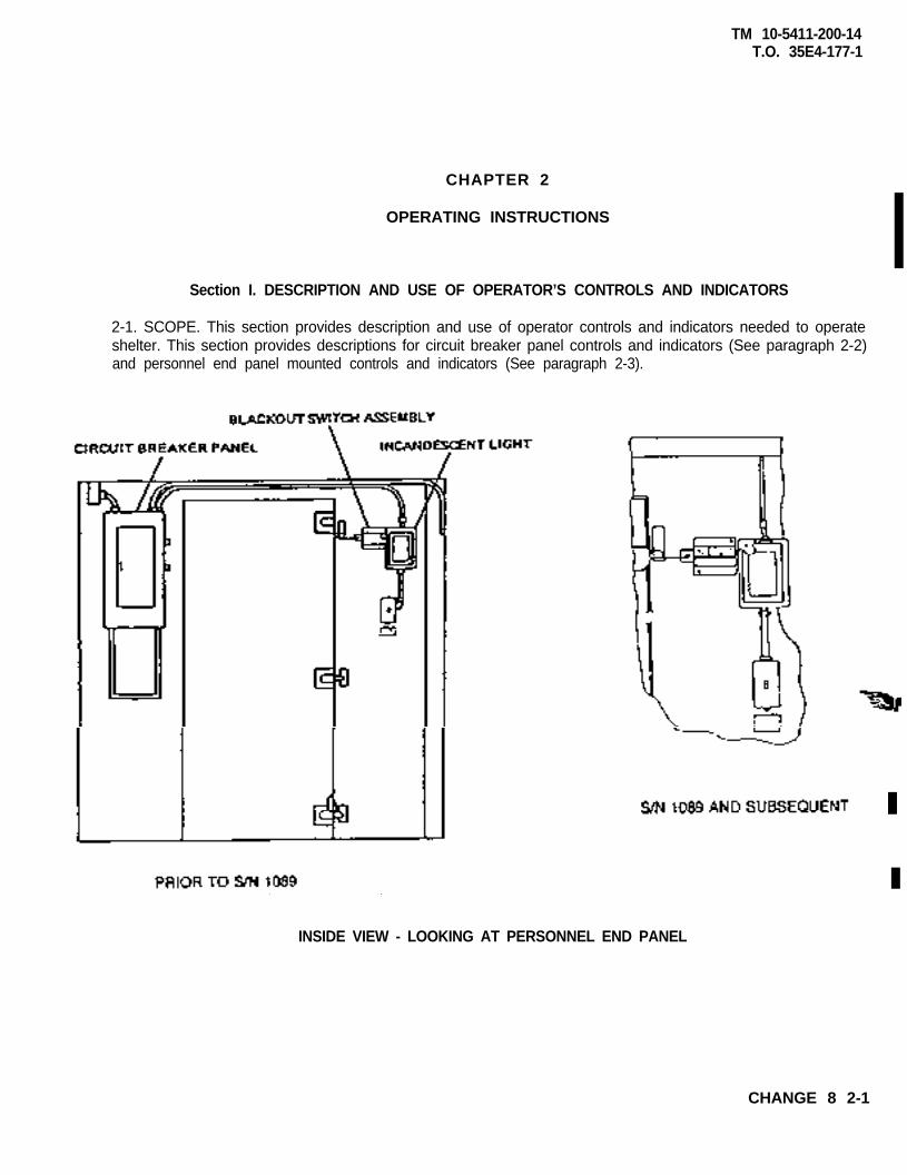
2-1. SCOPE. This section provides description and use of operator controls and indicators needed to operateshelter. This section provides descriptions for circuit breaker panel controls and indicators (See paragraph 2-2)and personnel end panel mounted controls and indicators (See paragraph 2-3).
INSIDE VIEW - LOOKING AT PERSONNEL END PANEL
CHANGE 8 2-1
TM 10-5411-200-14T.O. 35E4-177-1
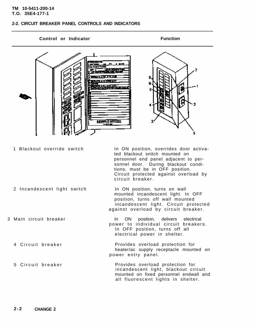
2-2. CIRCUIT BREAKER PANEL CONTROLS AND INDICATORS
Control or Indicator Function
1 B lackou t ove r r i de sw i t ch In ON posit ion, overr ides door act iva-ted blackout snitch mounted onpersonnel end panel adjacent to per-sonnel door. During blackout condi-tions, must be in OFF position.Circuit protected against overload byc i r cu i t b reake r .
2 I ncandescen t l i gh t sw i t ch In ON position, turns on wallmounted incandescent light. In OFFposit ion, turns off wal l mountedincandescent l igh t . C i rcu i t p ro tec ted
aga ins t ove r l oad by c i r cu i t b reake r .
3 Main c i rcu i t breaker In ON position, delivers electricalpower t o i nd i v i dua l c i r cu i t b reake rs .
In OFF posit ion, turns off al le lec t r ica l power in she l ter .
4 C i r c u i t b r e a k e r
5 C i r c u i t b r e a k e r
Provides overload protect ion forheater/ac supply receptacle mounted on
power en t r y pane l .
Provides overload protect ion forincandescent l igh t , b lackout c i rcu i tmounted on fixed personnel endwall anda l l f l uo rescen t l i gh t s i n she l t e r .
2 - 2 CHANGE 2
TM 10-5411-200-14T.O. 35E4-177-1
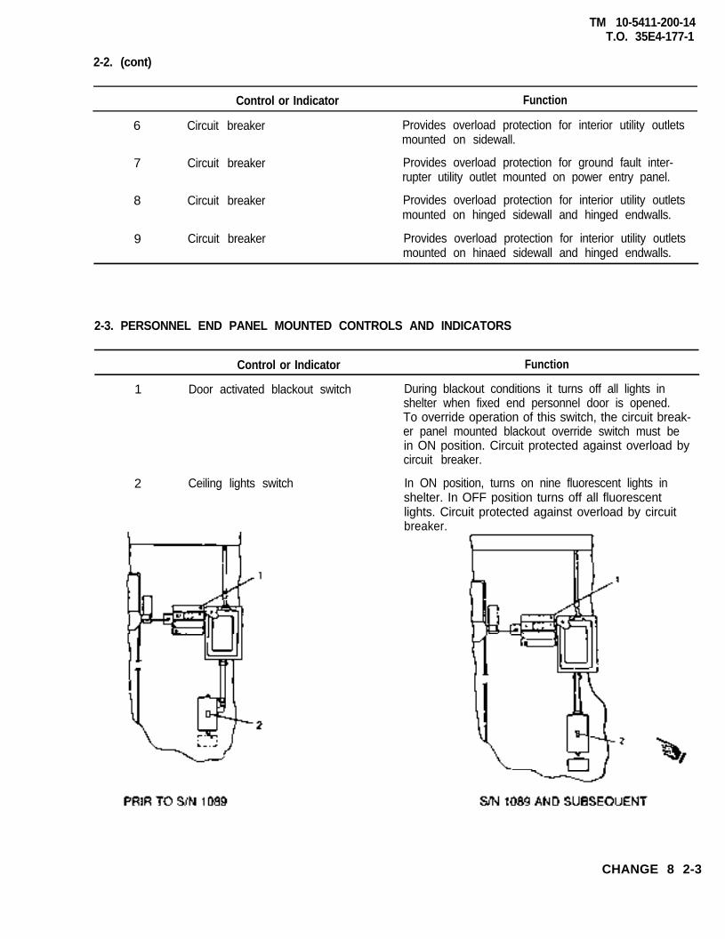
2-2. (cont)
Control or Indicator Function
6 Circuit breaker Provides overload protection for interior utility outletsmounted on sidewall.
7 Circuit breaker Provides overload protection for ground fault inter-rupter utility outlet mounted on power entry panel.
8 Circuit breaker Provides overload protection for interior utility outletsmounted on hinged sidewall and hinged endwalls.
9 Circuit breaker Provides overload protection for interior utility outletsmounted on hinaed sidewall and hinged endwalls.
2-3. PERSONNEL END PANEL MOUNTED CONTROLS AND INDICATORS
Control or Indicator Function
1 Door activated blackout switch During blackout conditions it turns off all lights inshelter when fixed end personnel door is opened.To override operation of this switch, the circuit break-er panel mounted blackout override switch must bein ON position. Circuit protected against overload bycircuit breaker.
2 Ceiling lights switch In ON position, turns on nine fluorescent lights inshelter. In OFF position turns off all fluorescentlights. Circuit protected against overload by circuitbreaker.
CHANGE 8 2-3
TM 10-5411-200-14T.O. 35E4-177-1
Section II OPERATOR'S PREVENTIVE MAINTENANCE CHECKS AND SERVICES (PMCS.)
2-4. GENERAL. For the shelter to be ready for use at al l t imes, i t must beinspected systematically so that defects may be discovered and correctedbefore they result in serious damage or fai lure.
Before you operate. Always keep in mind the CAUTIONS and WARNINGS.Perform your "B-before" PMCS (Table 2-1).
b. While you operate. Always keep in mind the CAUTIONS and WARNINGS.Perform your "D-during" PMCS (Table 2-1).
c . Monthly. Always keep in mind the CAUTIONS and WARNINGS. Performyour "M-monthly" PMCS (Table 2-1).
d . I f your equipment fa i ls to operate , troubleshoot with proper equip-ment. Repor t def ic ienc ies as fo l lows:
(1) (A) Users report in accordance with DA PAM 738-750.
(2) (P) Users refer to appl icable inspection manuals and work cardsets in the TO 35C2-3 series for periodic requirements and the PMCS Table fordetai led procedures.
2-5. SPECIAL INSTRUCTIONS. The fol lowing actions apply while performing yourPMCS:
a . Stop operation immediately i f deficiency is noted during operationwhich would damage the equipment.
b . Defects discovered during operation of the equipment should be notedfor future correction to be made as soon as operation has ceased.
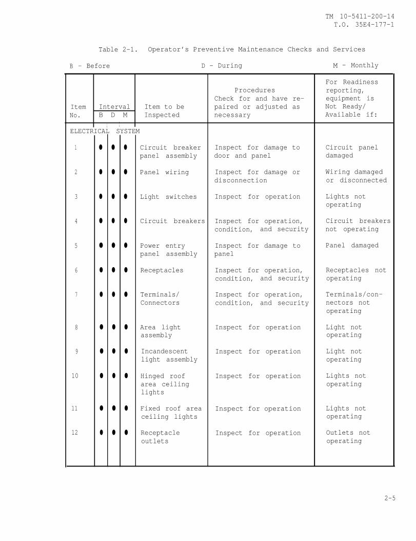
2-6. PREVENTIVE MAINTENANCE CHECKS AND SERVICES TABLE. Tab le 2 -1 l i s t s a l lPMCS to be performed by the operator.
NOTE
I f the equipment must be kept in continuous operation,check and service only those items that can be checkedand serv iced wi thout d is turb ing operat ion. Make thecomplete checks and services when the equipment can beshut down. Inspect she l ter for leaks.
2-4
TM 10-5411-200-14T.O. 35E4-177-1
For ReadinessProcedures reporting,
Check for and have re- equipment isItem Interval Item to be paired or adjusted as Not Ready/No. B D M Inspected necessary Available if:
I IELECTRICAL SYSTEM
1 ● ● ● Circuit breaker Inspect for damage to Circuit panelpanel assembly door and panel damaged
2 ● ● ● Panel wiring Inspect for damage or Wiring damageddisconnection or disconnected
3 ● ● ● Light switches Inspect for operation Lights notoperating
4 ● ● ● Circuit breakers Inspect for operation, Circuit breakerscondition, and security not operating
5 ● ● ● Power entry Inspect for damage to Panel damagedpanel assembly panel
6 ● ● ● Receptacles Inspect for operation, Receptacles notcondition, and security operating
7 ● ● ● Terminals/ Inspect for operation, Terminals/con-Connectors condition, and security nectors not
operating
8 ● ● ● Area light Inspect for operation Light notassembly operating
9 ● ● ● Incandescent Inspect for operation Light notlight assembly operating
10 ● ● ● Hinged roof Inspect for operation Lights notarea ceiling operatinglights
11 ● ● ● Fixed roof area Inspect for operation Lights notceiling lights operating
12 ● ● ● Receptacle Inspect for operation Outlets notoutlets operating
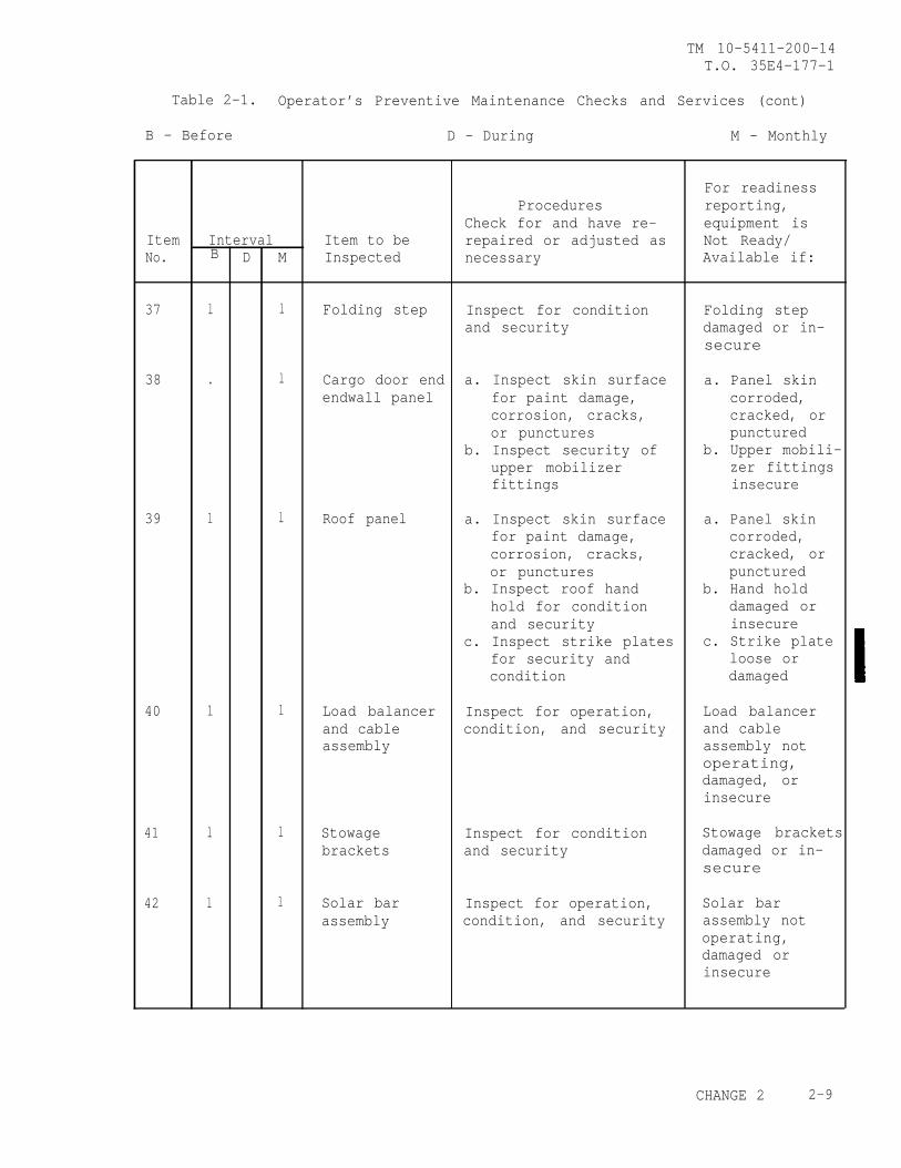
Table 2-1. Operator’s Preventive Maintenance Checks and Services
B - Before D - During M - Monthly
2-5
TM 10-5411-200-14T.O. 35E4-177-1
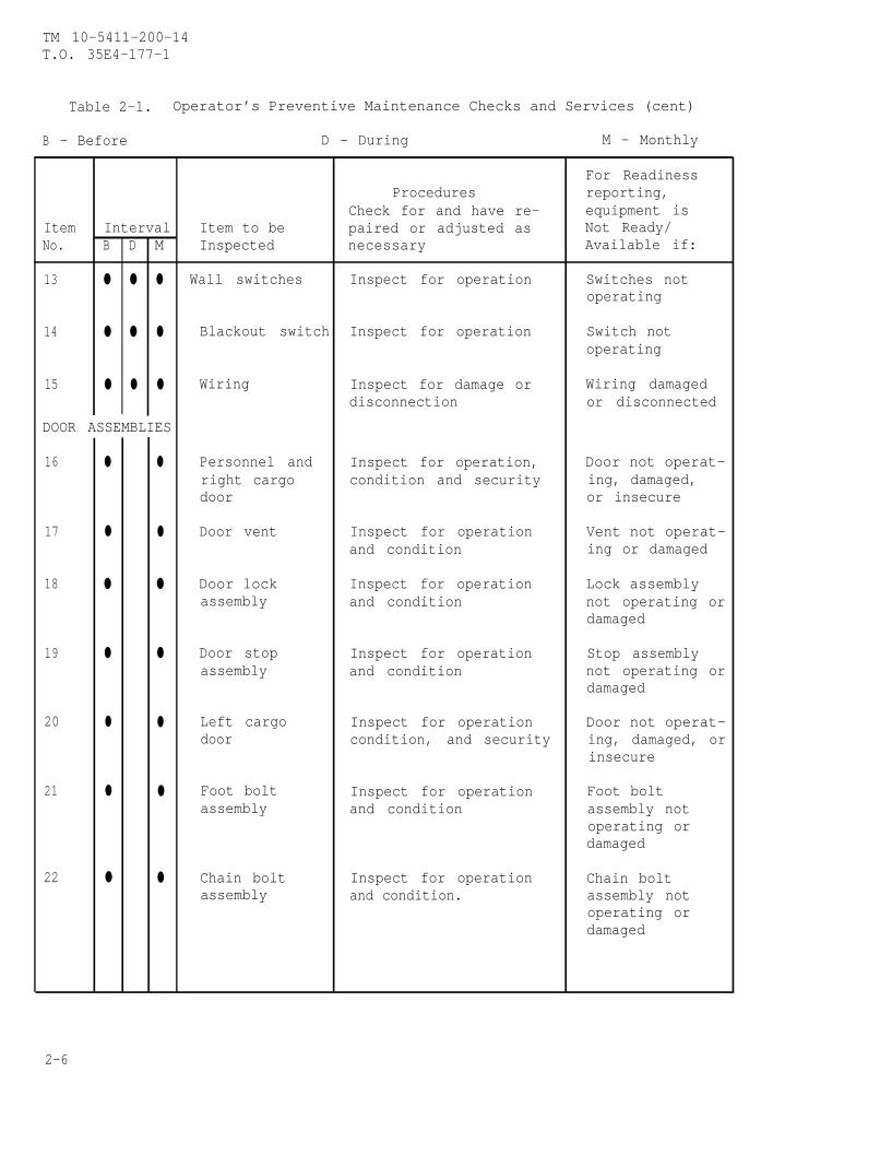
Table 2-1. Operator’s Preventive Maintenance Checks and Services (cent)
B - Before D - During M - Monthly
For ReadinessProcedures reporting,
Check for and have re- equipment isItem Interval Item to be paired or adjusted as Not Ready/No. B D M Inspected necessary Available if:
13 ● ● ● Wall switches Inspect for operation Switches notoperating
14 ● ● ● Blackout switch Inspect for operation Switch notoperating
15 ● ● ● Wiring Inspect for damage or Wiring damageddisconnection or disconnected
DOOR ASSEMBLIES
16 ● ● Personnel and Inspect for operation, Door not operat-right cargo condition and security ing, damaged,door or insecure
17 ● ● Door vent Inspect for operation Vent not operat-and condition ing or damaged
18 ● ● Door lock Inspect for operation Lock assemblyassembly and condition not operating or
damaged
19 ● ● Door stop Inspect for operation Stop assemblyassembly and condition not operating or
damaged
20 ● ● Left cargo Inspect for operation Door not operat-door condition, and security ing, damaged, or
insecure
21 ● ● Foot bolt Inspect for operation Foot boltassembly and condition assembly not
operating ordamaged
22 ● ● Chain bolt Inspect for operation Chain boltassembly and condition. assembly not
operating ordamaged
2-6
TM 10-5411-200-14T.O. 35E4-177-1
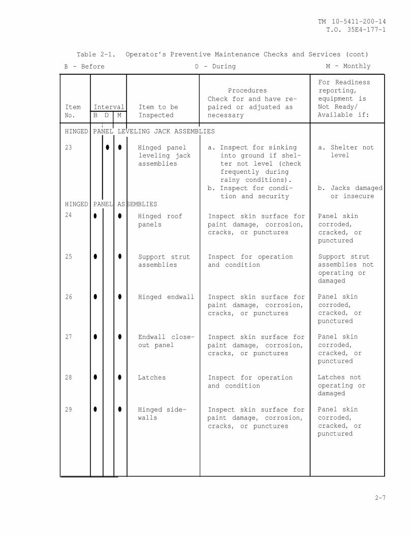
Table 2-1. Operator’s Preventive Maintenance Checks and Services (cont)
B - Before D - During M - Monthly
For ReadinessProcedures reporting,
Check for and have re- equipment isItem Interval Item to be paired or adjusted as Not Ready/No. B D M Inspected necessary Available if:
IHINGED PANEL LEVELING JACK ASSEMBLIES
23 ● ● Hinged panel a. Inspect for sinking a. Shelter notleveling jack into ground if shel- levelassemblies ter not level (check
frequently duringrainy conditions).
b. Inspect for condi- b. Jacks damagedtion and security or insecure
HINGED PANEL ASSEMBLIES
24 ● ● Hinged roof Inspect skin surface for Panel skinpanels paint damage, corrosion, corroded,
cracks, or punctures cracked, orpunctured
25 ● ● Support strut Inspect for operation Support strutassemblies and condition assemblies not
operating ordamaged
26 ● ● Hinged endwall Inspect skin surface for Panel skinpaint damage, corrosion, corroded,cracks, or punctures cracked, or
punctured
27 ● ● Endwall close- Inspect skin surface for Panel skinout panel paint damage, corrosion, corroded,
cracks, or punctures cracked, orpunctured
28 ● ● Latches Inspect for operation Latches notand condition operating or
damaged
29 ● ● Hinged side- Inspect skin surface for Panel skinwalls paint damage, corrosion, corroded,
cracks, or punctures cracked, orpunctured
2-7
TM 10-5411-200-14T.O. 35E4-177-1
Table 2-1. Operator’s Preventive Maintenance Checks and Services (cont)
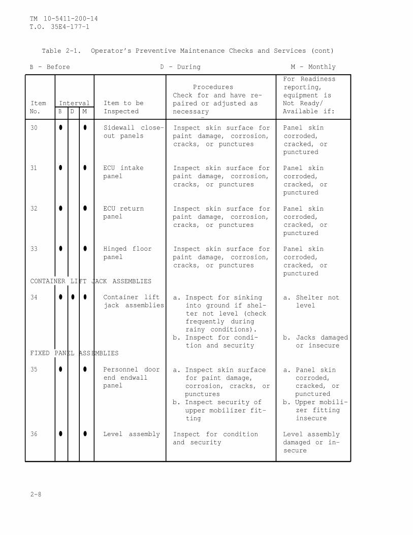
B - Before D - During M - Monthly
For ReadinessProcedures reporting,
Check for and have re- equipment isItem Interval Item to be paired or adjusted as Not Ready/No. B D M Inspected necessary Available if:
—
30 ● ● Sidewall close- Inspect skin surface for Panel skinout panels paint damage, corrosion, corroded,
cracks, or punctures cracked, orpunctured
31 ● ● ECU intake Inspect skin surface for Panel skinpanel paint damage, corrosion, corroded,
cracks, or punctures cracked, orpunctured
32 ● ● ECU return Inspect skin surface for Panel skinpanel paint damage, corrosion, corroded,
cracks, or punctures cracked, orpunctured
33 ● ● Hinged floor Inspect skin surface for Panel skinpanel paint damage, corrosion, corroded,
cracks, or punctures cracked, orpunctured
CONTAINER LIFT JACK ASSEMBLIES
34 ● ● ● Container lift a. Inspect for sinking a. Shelter notjack assemblies into ground if shel- level
ter not level (checkfrequently duringrainy conditions).
b. Inspect for condi- b. Jacks damagedtion and security or insecure
FIXED PANEL ASSEMBLIES
35 ● ● Personnel door a. Inspect skin surface a. Panel skinend endwall for paint damage, corroded,panel corrosion, cracks, or cracked, or
punctures puncturedb. Inspect security of b. Upper mobili-
upper mobilizer fit- zer fittingting insecure
36 ● ● Level assembly Inspect for condition Level assemblyand security damaged or in-
secure
2-8
TM 10-5411-200-14T.O. 35E4-177-1
Table 2-1. Operator’s Preventive Maintenance Checks and Services (cont)
B - Before D - During M - Monthly
B
For readinessProcedures reporting,
Check for and have re- equipment isItem Interval Item to be repaired or adjusted as Not Ready/No. D M Inspected necessary Available if:
37 l l Folding step Inspect for condition Folding stepand security damaged or in-
secure
38 . l Cargo door end a. Inspect skin surface a. Panel skinendwall panel for paint damage, corroded,
corrosion, cracks, cracked, oror punctures punctured
b. Inspect security of b. Upper mobili-upper mobilizer zer fittingsfittings insecure
39 l l Roof panel a. Inspect skin surface a. Panel skinfor paint damage, corroded,corrosion, cracks, cracked, oror punctures punctured
b. Inspect roof hand b. Hand holdhold for condition damaged orand security insecure
c. Inspect strike plates c. Strike platefor security and loose orcondition damaged
40 l l Load balancer Inspect for operation, Load balancerand cable condition, and security and cableassembly assembly not
operating,damaged, orinsecure
41 l l Stowage Inspect for condition Stowage bracketsbrackets and security damaged or in-
secure
42 l l Solar bar Inspect for operation, Solar barassembly condition, and security assembly not
operating,damaged orinsecure
CHANGE 2 2-9

TM 10-5411-200-14T.O. 35E4-177-1
Table 2-1. Operator’s Preventive Maintenance Checks and Services (cent)
B - Before D - During M - Monthly
B D
For readinessProcedures reporting,
Check for and have re- equipment isItem Interval Item to be repaired or adjusted as Not Ready/No. H Inspected necessary Available if:
43 ● ● Floor panel Inspect skin surface Panel skinfor paint damage, cor- corroded,rosion, cracks, or cracked, orpunctures punctured
FRAME ASSEMBLY
44 ● ● Corner post Inspect for condition Corner post orand IS0 fit- and security IS0 fittingting assembly damaged or in-
secure
45 ● ● Camlock and Inspect for operation, Camlock or latchlatch cam condition, and security cam handle nothandle operating,
damaged, or in-secure
MISCELLANEOUS COMPONENTS
46 ● ● Equipment con- Inspect for condition Equipment con-tainer and completeness tainer damaged
or incomplete
47 ● ● storm Inspect for condition Storm configuraconfiguration and completeness tion componentscomponents damaged or in-
complete
48 l l Support braces Inspect for condition Support bracesdamaged
49 ● ● Leveling jack Inspect for condition Leveling jackextensions extensions
damaged
Skin surfaces that are punctured/damaged will allowwater entry into honeycomb panel. All punctures/holes of damaged areas must be covered immediatelypending permanent repair.
C A U T I O N
2-10 CHANGE 2
TM 10-5411-200-14T.O. 35E4-177-1
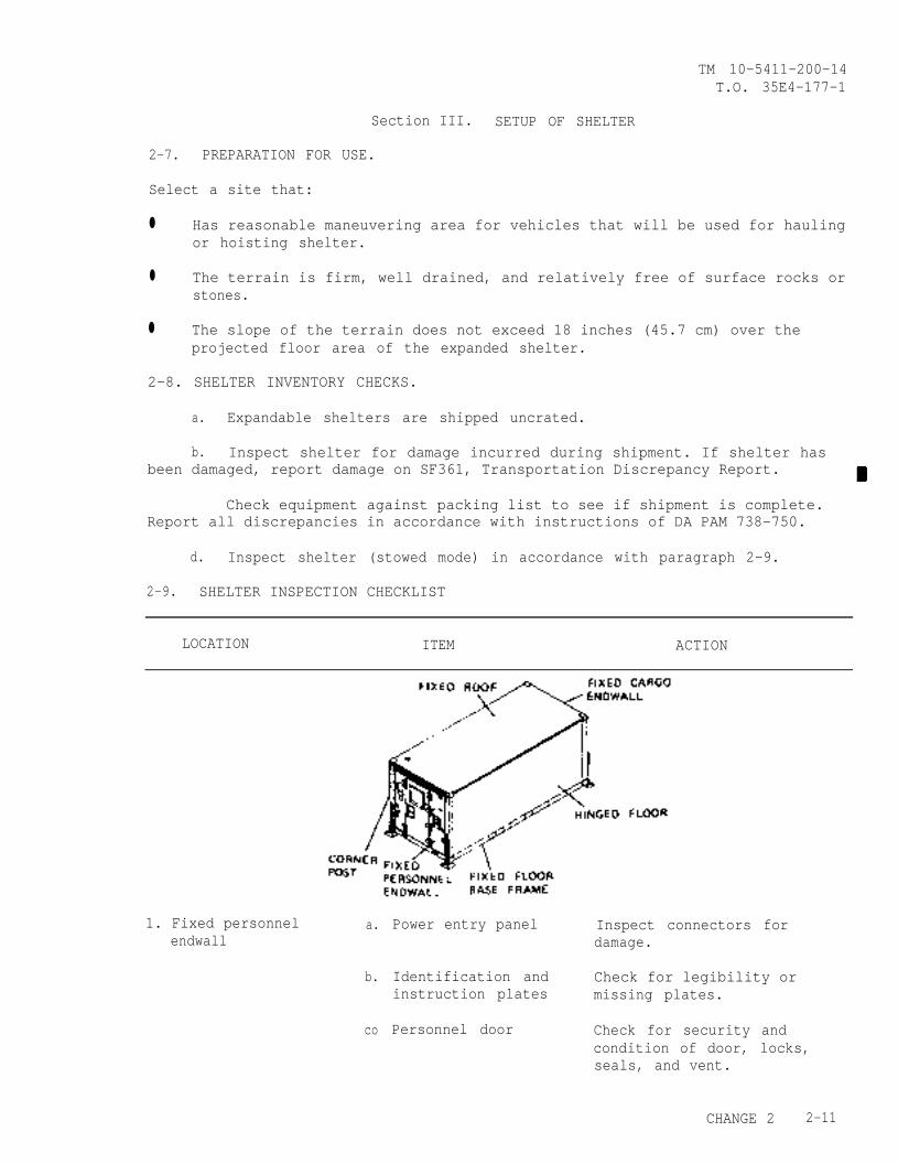
Section III. SETUP OF SHELTER
2-7. PREPARATION FOR USE.
Select a site that:
● Has reasonable maneuvering area for vehicles that will be used for haulingor hoisting shelter.
● The terrain is firm, well drained, and relatively free of surface rocks orstones.
● The slope of the terrain does not exceed 18 inches (45.7 cm) over theprojected floor area of the expanded shelter.
2-8. SHELTER INVENTORY CHECKS.
a. Expandable shelters are shipped uncrated.
b. Inspect shelter for damage incurred during shipment. If shelter hasbeen damaged, report damage on SF361, Transportation Discrepancy Report.
Check equipment against packing list to see if shipment is complete.Report all discrepancies in accordance with instructions of DA PAM 738-750.
d. Inspect shelter (stowed mode) in accordance with paragraph 2-9.
2-9. SHELTER INSPECTION CHECKLIST
LOCATION ITEM ACTION
1. Fixed personnel a.endwall
b.
co
Power entry panel Inspect connectors fordamage.
Identification and Check for legibility orinstruction plates missing plates.
Personnel door Check for security andcondition of door, locks,seals, and vent.
CHANGE 2 2-11
TM 10-5411-200-14T.0. 35E4-177-1
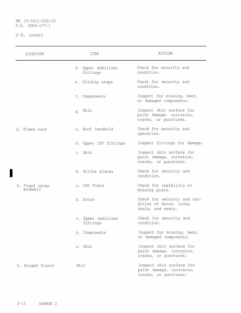
2-9. (cont)
LOCATION ITEM ACTION
2. Fixed roof
3. Fixed cargoendwall
4. Hinged floors
d.
e.
f.
g.
a.
b.
c.
d.
a.
b.
c.
d.
e.
Upper mobilizerfittings
Folding steps
Components
Skin
Roof handhold
Upper IS0 fittings
Skin
Strike plates
CSC Plate
Doors
Upper mobilizerfittings
Components
Skin
Skin
Check for security andcondition.
Check for security andcondition.
Inspect for missing, bent,or damaged components.
Inspect skin surface forpaint damage, corrosion,cracks, or punctures.
Check for security andoperation.
Inspect fittings for damage.
Inspect skin surface forpaint damage, corrosion,cracks, or punctures.
Check for security andcondition.
Check for legibility ormissing plate.
Check for security and con-dition of doors, locks,seals, and vents.
Check for security andcondition.
Inspect for missing, bent,or damaged components.
Inspect skin surface forpaint damage, corrosion,cracks, or punctures.
Inspect skin surface forpaint damage, corrosion,cracks, or punctures.
2-12 CHANGE 2
TM 10-5411-200-14T.O. 35E4-177-1
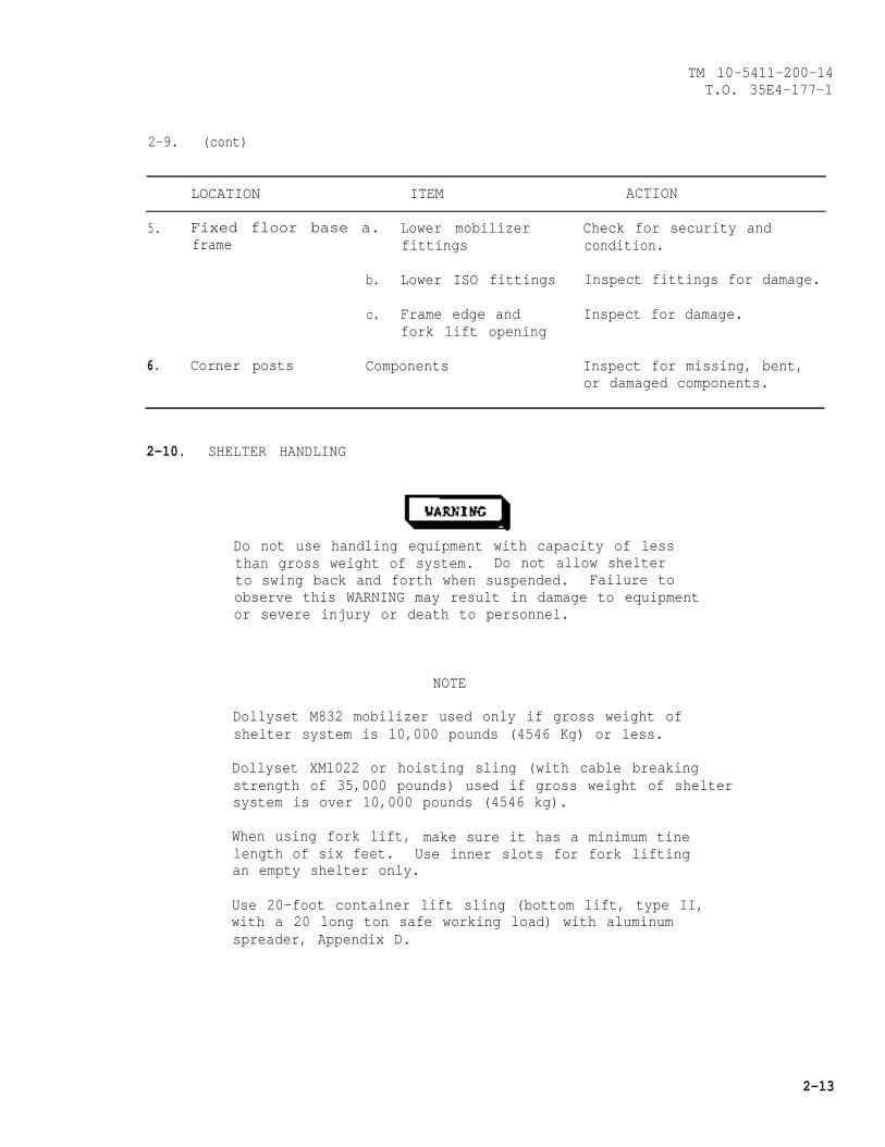
2-9. (cont)
LOCATION ITEM ACTION
5. Fixed floor base a. Lower mobilizer Check for security andframe fittings condition.
b. Lower ISO fittings Inspect fittings for damage.
c. Frame edge and Inspect for damage.fork lift opening
6. Corner posts Components Inspect for missing, bent,or damaged components.
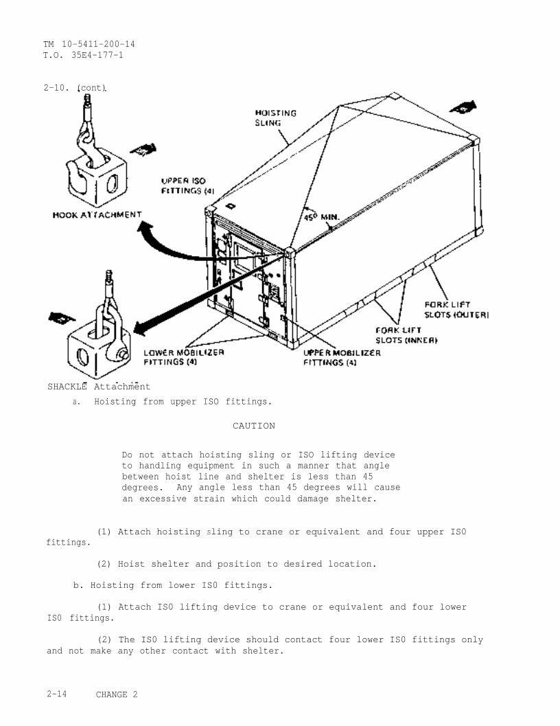
2-10. SHELTER HANDLING
Do not use handling equipment with capacity of lessthan gross weight of system. Do not allow shelterto swing back and forth when suspended. Failure toobserve this WARNING may result in damage to equipmentor severe injury or death to personnel.
NOTE
Dollyset M832 mobilizer used only if gross weight ofshelter system is 10,000 pounds (4546 Kg) or less.
Dollyset XM1022 or hoisting sling (with cable breakingstrength of 35,000 pounds) used if gross weight of sheltersystem is over 10,000 pounds (4546 kg).
When using fork lift, make sure it has a minimum tinelength of six feet. Use inner slots for fork liftingan empty shelter only.
Use 20-foot container lift sling (bottom lift, type II,with a 20 long ton safe working load) with aluminumspreader, Appendix D.
2-13
TM 10-5411-200-14T.O. 35E4-177-1
2-10. (cont)
SHACKLE Attachment
a. Hoisting from upper ISO fittings.
CAUTION
Do not attach hoisting sling or ISO lifting deviceto handling equipment in such a manner that anglebetween hoist line and shelter is less than 45degrees. Any angle less than 45 degrees will causean excessive strain which could damage shelter.
(1) Attach hoisting Sling to crane or equivalent and four upper IS0fittings.
(2) Hoist shelter and position to desired location.
b. Hoisting from lower IS0 fittings.
(1) Attach IS0 lifting device to crane or equivalent and four lowerIS0 fittings.
(2) The IS0 lifting device should contact four lower IS0 fittings onlyand not make any other contact with shelter.
2-14 CHANGE 2

TM 10-5411-200-14T.O. 35E4-177-I
2-10, (cont)
(3) Terminal fittings shall be installed so that lifting forces areexerted not more than 1-1/2 in. (38 mm) away from ISO fittings.
(4) Hoist shelter and position to desired location.
c. Fork lifting from fork lift slots in base frame.
(1) Fork lift arms shall be at least 6 ft (1.8 m) long.
(2) Use care when inserting fork lift arms in fork lift slots.
(3) Use inner slots for fork lifting an empty shelter only.
(4) Use outer slots for fork lifting shelter with maximum payload.
d. Dollyset lifting from mobilizer fittings.
(1) Separate Dollyset sections and prepare for use observing allrecommendations of Dollyset technical manual.
(2) Position. Dollyset sections at ends of shelter adjacent tomobilizer fittings at shelter endwalls.
(3) Position Dollyset brackets to connect with shelter mobilizerfittings and secure Dollyset to shelter.
2-15
TM 10-5411-200-14T.O. 35E4-177-1
2-10. (cont)
(4) Operate Dollyset according to Dollyset technical manual toraise shelter to towing height.
(5) Connect towing equipment to Dollyset tow bar.
(6) When shelter is in desired position, operate Dollyset to lowershelter and remove Dollyset sections.
e. Dollyset lifting from ISO fittings.
(1) Separate Dollyset sections and prepare for use observing allrecommendations of Dollyset technical manual.
(2) Position Dollyset sections at ends of shelter adjacent to ISOfittings at shelter endwalls.
(3) Position Dollyset brackets to connect with shelter IS0 fittingsand secure Dollyset to shelter.
(4) Operate Dollyset according to Dollyset technical manual toraise shelter to towing height.
(5) Connect towing equipment to Dollyset tow bar.
(6) When shelter is in desired position, operate Dollyset to lowershelter and remove Dollyset sections.
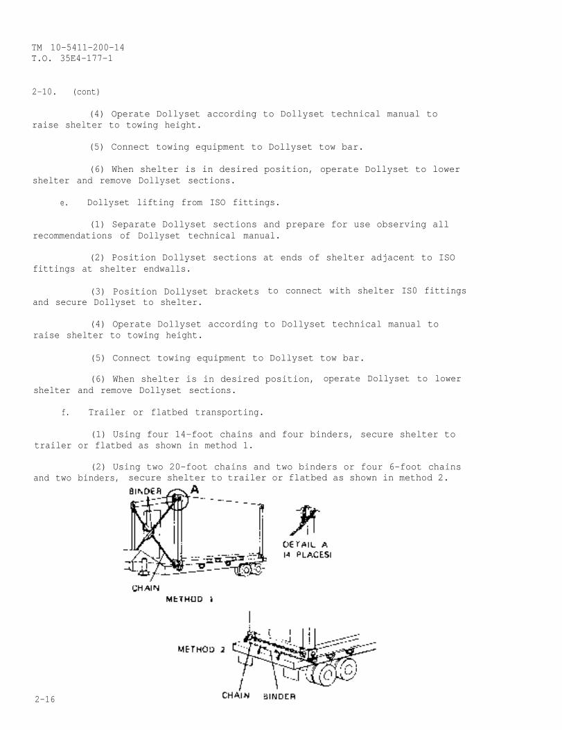
f. Trailer or flatbed transporting.
(1) Using four 14-foot chains and four binders, secure shelter totrailer or flatbed as shown in method 1.
(2) Using two 20-foot chains and two binders or four 6-foot chainsand two binders, secure shelter to trailer or flatbed as shown in method 2.
2-16
TM 10-5411-200-14T.O. 35E4-177-1
2 - 1 0 . ( c o n t )
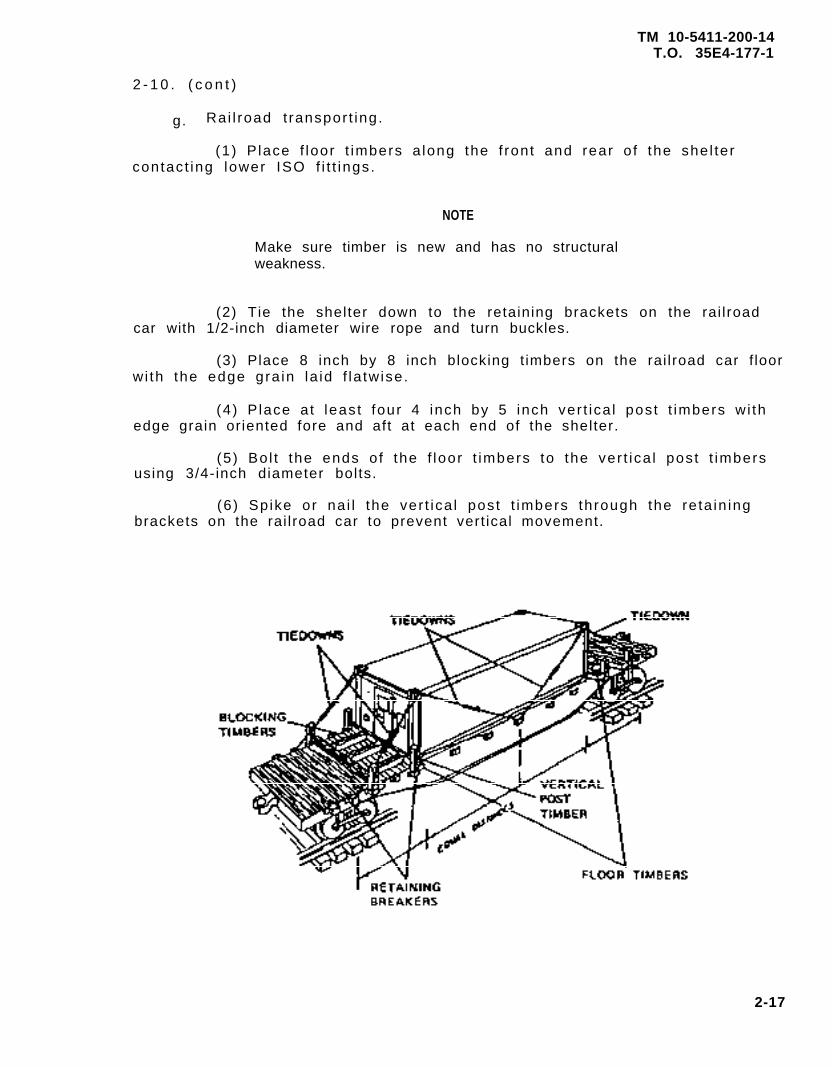
g. Rai l road t ranspor t ing.
(1) P lace f loor t imbers a long the f ront and rear o f the she l tercontact ing lower ISO f i t t ings.
NOTE
Make sure timber is new and has no structuralweakness.
(2) Tie the shelter down to the retaining brackets on the rai lroadcar with 1/2-inch diameter wire rope and turn buckles.
(3) Place 8 inch by 8 inch blocking t imbers on the rai lroad car f loorwi th the edge gra in la id f la tw ise.
(4) P lace a t least four 4 inch by 5 inch ver t ica l post t imbers wi thedge grain oriented fore and aft at each end of the shelter.
(5) Bo l t the ends o f the f loor t imbers to the ver t ica l post t imbersusing 3/4-inch diameter bolts.
(6) Sp ike or na i l the ver t ica l post t imbers through the re ta in ingbrackets on the rai lroad car to prevent vert ical movement.
2-17
5411-01-136-9838
PART NO: 5-4 3118
81337
5411-01-136-9838
81337
PART NO: 5-4-3201
5411-01-294-9866
5411-01-294-9866
TM 10-5411-200-14T.O. 35E4-177-1
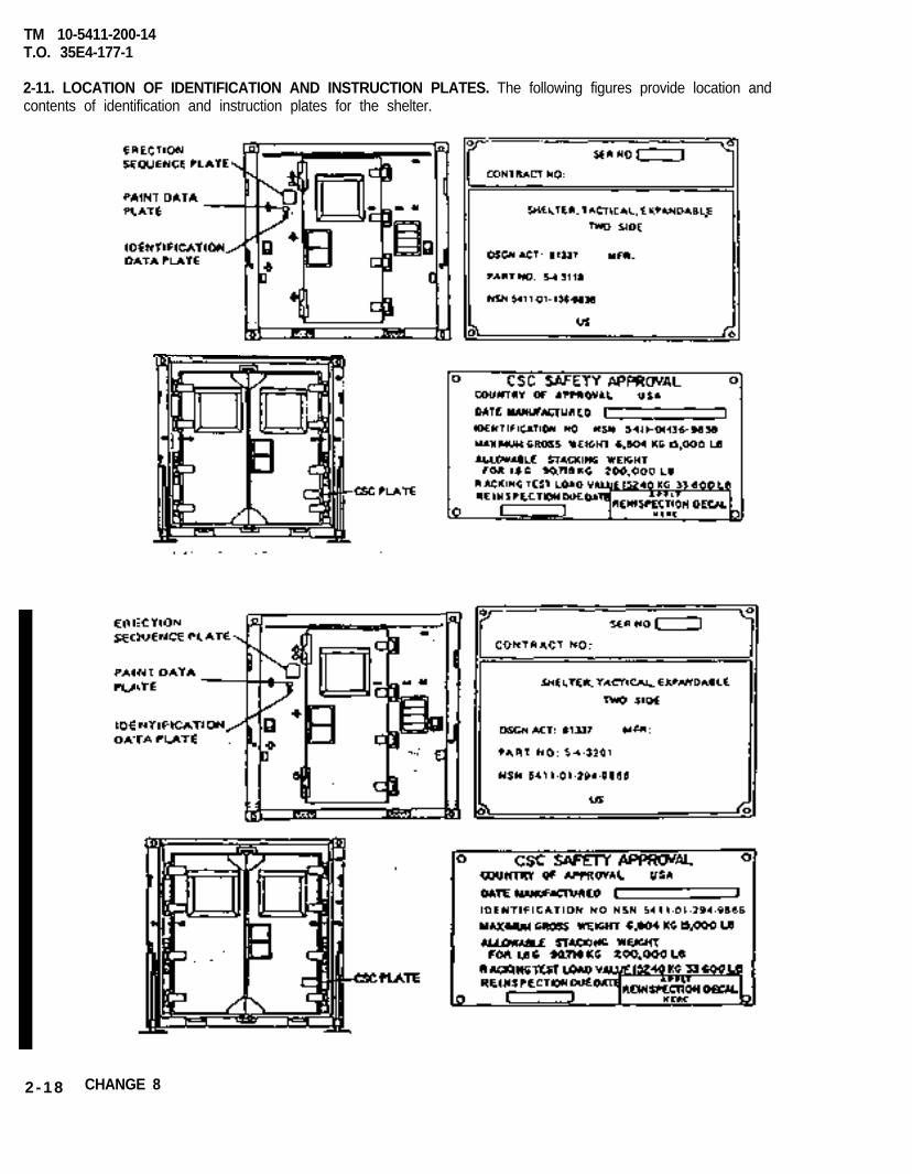
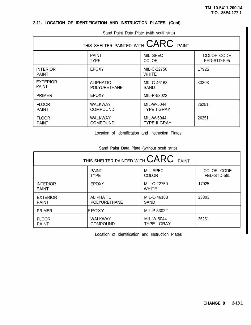
2-11. LOCATION OF IDENTIFICATION AND INSTRUCTION PLATES. The following figures provide location andcontents of identification and instruction plates for the shelter.
2-18 CHANGE 8
TM 10-5411-200-14T.O. 35E4-177-1
2-11. LOCATION OF IDENTlFlCATlON AND INSTRUCTION PLATES. (Cont)
Sand Paint Data Plate (with scuff strip)
THIS SHELTER PAINTED WITH CARC PAINT
PAINTTYPE
MIL SPECCOLOR
COLOR CODEFED-STD-595
INTERIORPAINT
EXTERIORPAINT
EPOXY MIL-C-22750 17925WHITE
ALIPHATICPOLYURETHANE
MIL-C-46168 33303SAND
PRIMER EPOXY MIL-P-53022
FLOORPAINT
WALKWAYCOMPOUND
MIL-W-5044TYPE I GRAY
26251
FLOORPAINT
WALKWAY MIL-W-5044COMPOUND TYPE II GRAY
Location of Identification and Instruction Plates
26251
Sand Paint Data Plate (without scuff strip)
THIS SHELTER PAINTED WITH CARC PAINT
INTERIORPAINT
EXTERIORPAINT
PRIMER
FLOORPAINT
PAINTTYPE
EPOXY
ALIPHATICPOLYURETHANE
EPOXY
WALKWAYCOMPOUND
MIL SPECCOLOR
COLOR CODEFED-STD-595
MIL-C-22750 17925WHITE
MIL-C-46168 33303SAND
MIL-P-53022
MIL-W-5044TYPE I GRAY
26251
Location of Identification and Instruction Plates
CHANGE 8 2-18.1

TM 10-5411-200-14T.O.35E4-177-1
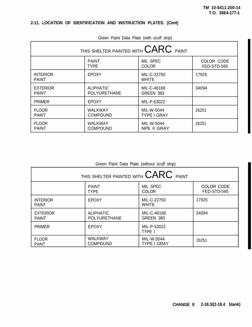
2-11. LOCATION OF IDENTIFICATION AND INSTRUCTION PLATES. (Cont)
Camouflage Paint Data Plate (with scuff strip)
THIS SHELTER PAINTED WITH CARC PAINT
INTERIORPAINT
EXTERIORPAINT
PRIMER
FLOORPAINT
FLOORPAINT
PAINTTYPE
EPOXY
ALIPHATICPOLYURETHANE
E P O X Y
WALKWAYCOMPOUND
WALKWAYCOMPOUND
MIL SPECCOLOR
MIL-G22750GLOSS WHlTE
MlL-C-46168GREEN 383BROWN 383BLACK
MIL-P-53022
MIL-W-5044TYPE I GRAY
MIL-W-5044TYPE II GRAY
COLOR CODEFED-STD-595
17925
340943005137030
26251
26251
Camouflage Paint Date Plate (without scuff strip)
THIS SHELTER PAINTED WITH CARC PAINT
PAINT MIL SPEC COLOR CODETYPE COLOR FED-STD-595
INTERIOR EPOXY MIL-C-22750 17925PAIN-ILL WHITE
EXTERIORPAINT
ALIPHATICPOLYURETHANE
MIL-C-46168GREEN 383 34094BROWN 383 30051BLACK 37030
PRIMER EPOXY MIL-P-53022
FLOOR WALKWAY MIL-00-5044 26251P A I N T COMPOUND TYPE I GRAY
2-18.2 CHANGE 8
TM 10-5411-200-14T.O. 35E4-177-1
2-11. LOCATION OF IDENTIFICATION AND INSTRUCTION PLATES. (Cont)
Green Paint Data Plate (with scuff strip)
THIS SHELTER PAINTED WITH CARC PAINT
INTERIORPAINT
EXTERIORPAINT
PRIMER
FLOORPAINT
FLOORPAINT
PAINTTYPE
EPOXY
ALIPHATICPOLYURETHANE
EPOXY
WALKWAYCOMPOUND
WALKWAYCOMPOUND
MIL SPECCOLOR
MIL-C-22750WHITE
MIL-C-46168GREEN 383
MIL-P-53022
MIL-W-5044TYPE I GRAY
MIL-W-5044NPE II GRAY
COLOR CODEFED-STD-595
17925
34094
26251
26251
Green Paint Data Plate (without scuff strip)
THIS SHELTER PAINTED WITH CARC PAINT
INTERIORPAINT
EXTERIORPAINT
PRIMER
PAINTTYPE
EPOXY
ALIPHATICPOLYURETHANE
EPOXY
MIL SPECCOLOR
MIL-C-22750WHITE
MIL-C-46168GREEN 383
MIL-P-53022TYPE I
COLOR CODEFED-STD-595
17925
34094
FLOOR WALKWAY MIL-W-5044PAINT COMPOUND TYPE I GRAY
26251
CHANGE 8 2-18.3/(2-18.4 blank)

TM 10-5411-200-14T.O. 35E4-177-1
2-11 . (con t )
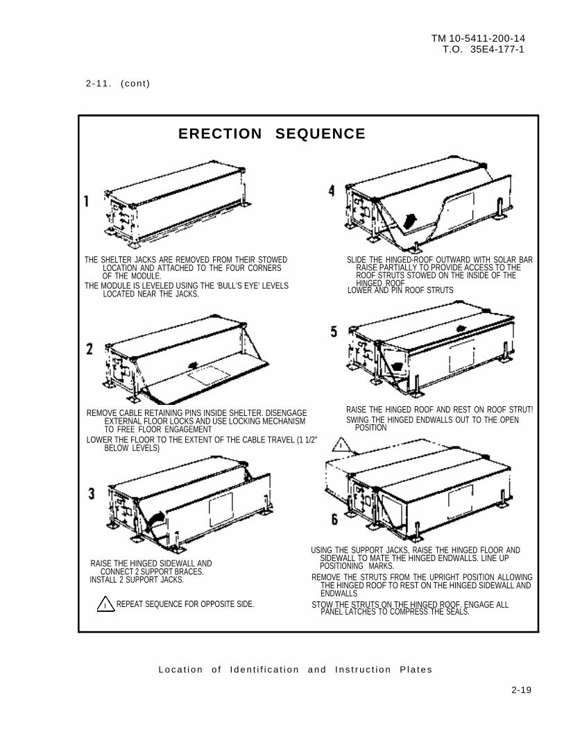
ERECTION SEQUENCE
THE SHELTER JACKS ARE REMOVED FROM THEIR STOWED SLIDE THE HINGED-ROOF OUTWARD WITH SOLAR BARLOCATION AND ATTACHED TO THE FOUR CORNERS RAISE PARTIALLY TO PROVIDE ACCESS TO THEOF THE MODULE. ROOF STRUTS STOWED ON THE INSIDE OF THE
THE MODULE IS LEVELED USING THE ‘BULL’S EYE’ LEVELSLOCATED NEAR THE JACKS.
HINGED ROOFLOWER AND PIN ROOF STRUTS
REMOVE CABLE RETAINING PINS INSIDE SHELTER. DlSENGAGE RAISE THE HINGED ROOF AND REST ON ROOF STRUT!EXTERNAL FLOOR LOCKS AND USE LOCKING MECHANISM SWING THE HINGED ENDWALLS OUT TO THE OPENTO FREE FLOOR ENGAGEMENT POSITION
LOWER THE FLOOR TO THE EXTENT OF THE CABLE TRAVEL (1 1/2"BELOW LEVELS)
RAISE THE HINGED SIDEWALL ANDCONNECT 2 SUPPORT BRACES.
INSTALL 2 SUPPORT JACKS.
USING THE SUPPORT JACKS, RAISE THE HINGED FLOOR ANDSlDEWALL TO MATE THE HINGED ENDWALLS. LINE UPPOSITIONING MARKS.
REMOVE THE STRUTS FROM THE UPRIGHT POSITION ALLOWINGTHE HINGED ROOF TO REST ON THE HINGED SIDEWALL ANDENDWALLS
REPEAT SEQUENCE FOR OPPOSITE SIDE. STOW THE STRUTS ON THE HINGED ROOF. ENGAGE ALLPANEL LATCHES TO COMPRESS THE SEALS.
L o c a t i o n o f I d e n t i f i c a t i o n a n d I n s t r u c t i o n P l a t e s
2-19
TM 10-5411-200-14T.O. 35E4-177-1
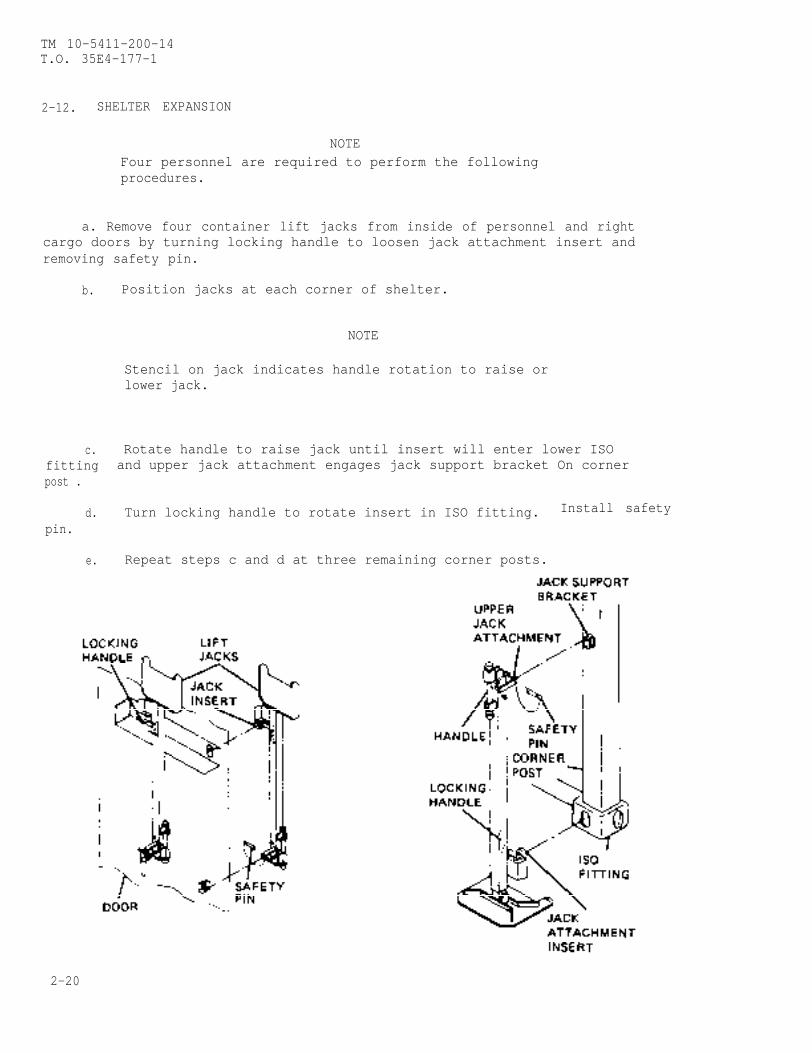
2-12. SHELTER EXPANSION
NOTEFour personnel are required to perform the followingprocedures.
a. Remove four container lift jacks from inside of personnel and rightcargo doors by turning locking handle to loosen jack attachment insert andremoving safety pin.
b. Position jacks at each corner of shelter.
NOTE
Stencil on jack indicates handle rotation to raise orlower jack.
c. Rotate handle to raise jack until insert will enter lower ISOfitting and upper jack attachment engages jack support bracket On cornerpost .
d. Turn locking handle to rotate insert in ISO fitting. Install safety
pin.
e. Repeat steps c and d at three remaining corner posts.
2-20
TM 10-5411-200-14T.O. 35E4-177-1
2-12. (cont)
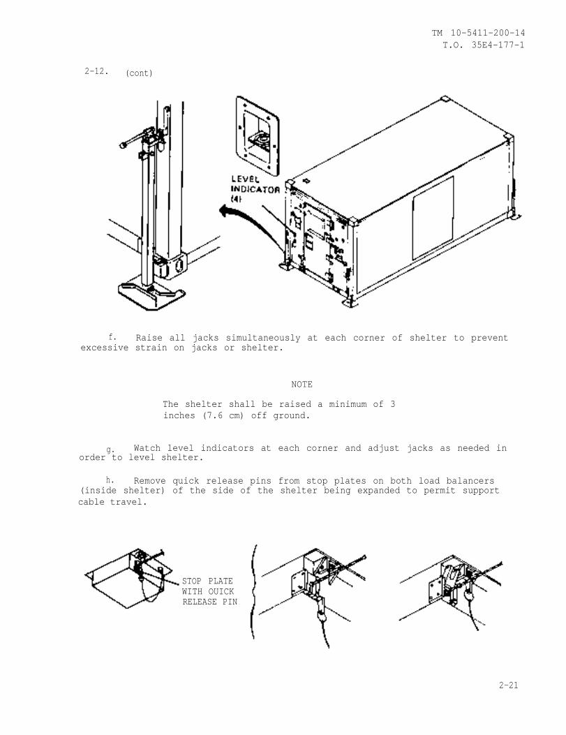
f. Raise all jacks simultaneously at each corner of shelter to preventexcessive strain on jacks or shelter.
NOTE
The shelter shall be raised a minimum of 3inches (7.6 cm) off ground.
g. Watch level indicators at each corner and adjust jacks as needed inorder to level shelter.
h. Remove quick release pins from stop plates on both load balancers(inside shelter) of the side of the shelter being expanded to permit supportcable travel.
STOP PLATEWITH OUICKRELEASE PIN
2-21
TM 10-5411-200-14T.O. 35E4-177-1
2-12. (cont)
WARNING
Expandable section (hinged floor and hinged sidewalltogether) weighs 700 pounds (318 kg). Do not standdirectly in front of hinged section.
i. Raise cam lock handles on corner posts and rotate as indicated todisengage hinged floor locks.
Carefully lower hinged floor to the extent of support cable travel(1-1/2 in. (3.8 cm) below level).
W A R N I N GThe stop plate cable assembly is a spring poweredmechanism. Personal injury or death may result iftwo quick release pins are not installed in thestop plates.
k. Install. two quick release pins in stop plates on load balancers(inside shelter) to prevent return of support cable.
l. Remove two support braces from equipment container.
m. Raise hinged sidewall and hold in position.
n. Install the two support braces in brace cups on hinged floor andsidewall behind support cable.
o. Remove two leveling jacks from inside of left cargo door.
p. Position jacks at each corner of expanded side.
2-22 CHANGE 2
TM 10-5411-200-14T.O. 35E4-177-1
2-12. (cont)
NOTE
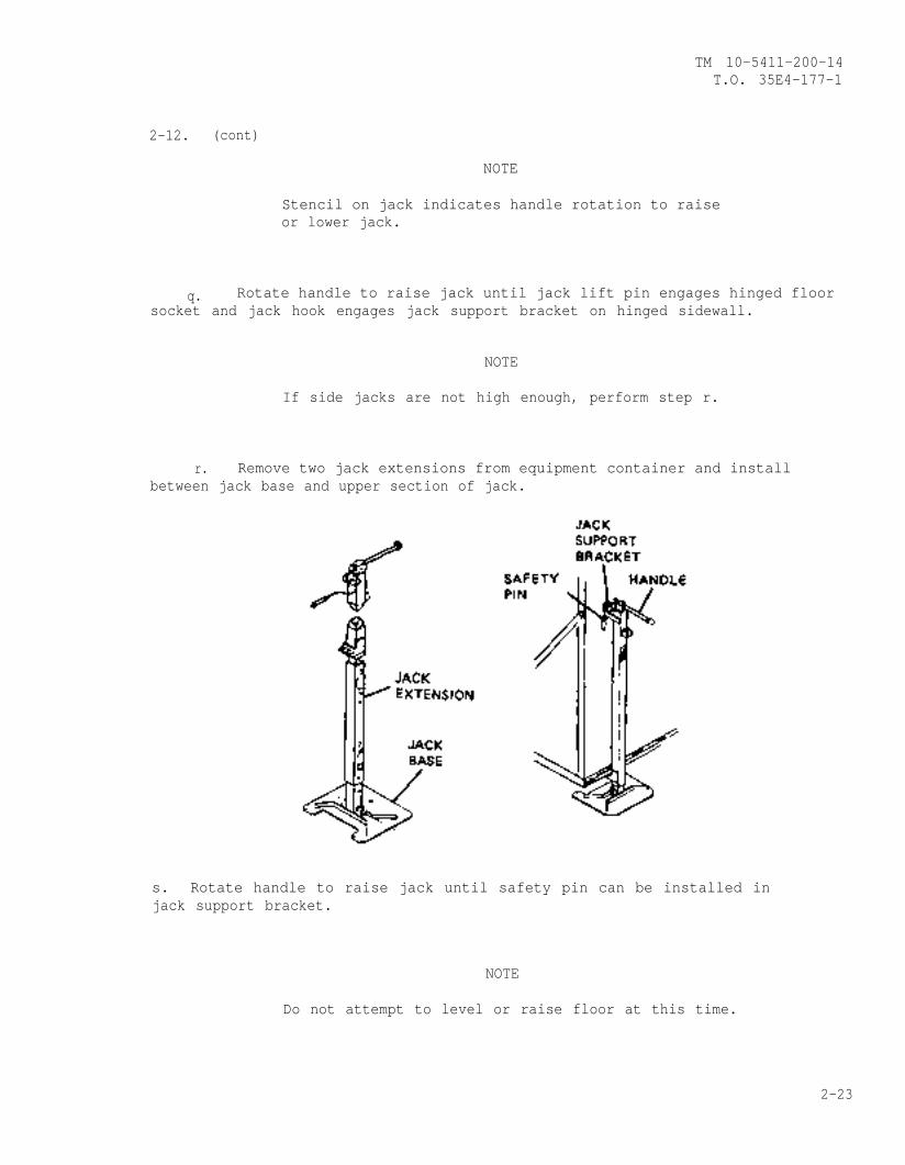
Stencil on jack indicates handle rotation to raiseor lower jack.
q. Rotate handle to raise jack until jack lift pin engages hinged floorsocket and jack hook engages jack support bracket on hinged sidewall.
NOTE
If side jacks are not high enough, perform step r.
r. Remove two jack extensions from equipment container and installbetween jack base and upper section of jack.
s. Rotate handle to raise jack until safety pin can be installed injack support bracket.
NOTE
Do not attempt to level or raise floor at this time.
2-23
TM 10-5411-200-14T.O. 35E4-177-1
2-12. (cont)
WARNING
2-12.
Door vents are spring loaded to swing upward. To prevent injury,hold door vent shut while unlatching all the retaining clips.
(cont)
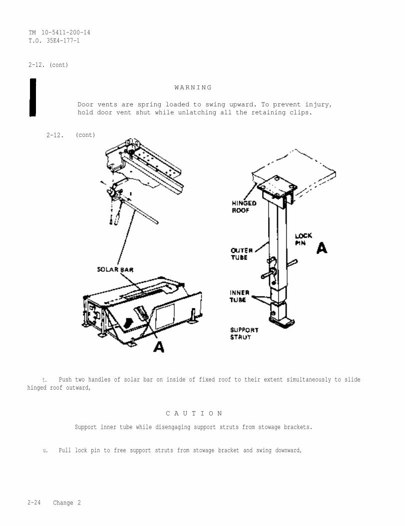
t. Push two handles of solar bar on inside of fixed roof to their extent simultaneously to slidehinged roof outward,
C A U T I O N
Support inner tube while disengaging support struts from stowage brackets.
u. Pull lock pin to free support struts from stowage bracket and swing downward,
2-24 Change 2

TM 10-5411-200-14T.O. 35E4-177-1
2-12. (cont)
v. Extendare in alignment.
inner tuba of strut and insert lock pin when pin holes in inner tube and outer tube
C A U T I O N
Do not force hinged roof to full height. This could cause damage to theroof and sidewall seal. Ensure that the hinged roof will clear the hingedsidewell prior to lifting.
w. Raise hinged roof to full height of struts using all four personnel: Two on support struts; twoto assist at roof.
Change 2 2-24.1/(2-24.2 blank)

TM 10-5411-200-14T.O. 35E4-177-1
2-12. (cont)
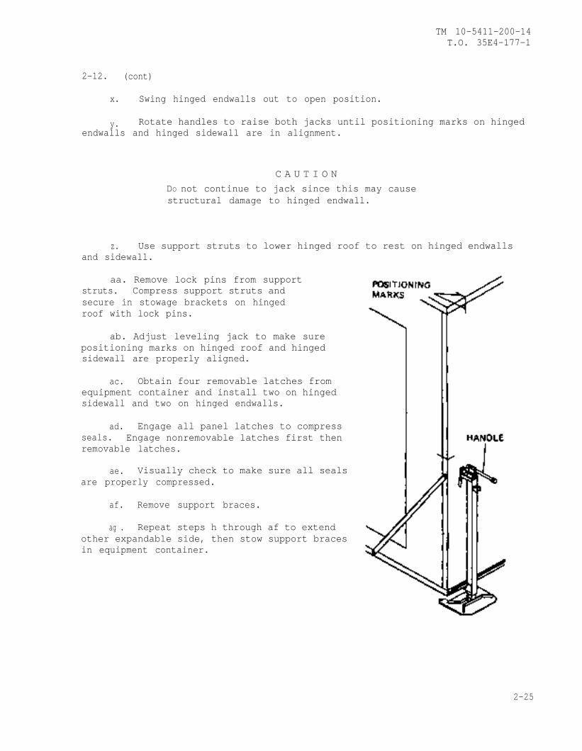
x. Swing hinged endwalls out to open position.
y. Rotate handles to raise both jacks until positioning marks on hingedendwalls and hinged sidewall are in alignment.
C A U T I O NDO not continue to jack since this may causestructural damage to hinged endwall.
z. Use support struts to lower hinged roof to rest on hinged endwallsand sidewall.
aa. Remove lock pins from supportstruts. Compress support struts andsecure in stowage brackets on hingedroof with lock pins.
ab. Adjust leveling jack to make surepositioning marks on hinged roof and hingedsidewall are properly aligned.
ac. Obtain four removable latches fromequipment container and install two on hingedsidewall and two on hinged endwalls.
ad. Engage all panel latches to compressseals. Engage nonremovable latches first thenremovable latches.
ae. Visually check to make sure all sealsare properly compressed.
af. Remove support braces.
ag . Repeat steps h through af to extendother expandable side, then stow support bracesin equipment container.
2-25
TM 10-5411-200-14T.O. 35E4-177-1
2-13. CEILING LIGHTS AND UTILITY OUTLETS INSTALLATION
a. Ceiling light installation.
W A R N I N G
In the event of lamp breakage, care must be taken inremoval of broken glass fragments and white phosphorousdust that may be dispersed within fixture. Inhalationof phosphorous dust could cause dangerous Injury.
(1) Set circuit breaker CB6 to “off” position.
(2) Remove power cord from stowage clip on ceiling.
(3) Depress plunger lock in fixed roof light stowage bracket.
(4) Move entire light fixture lengthwise toward power cord end todisengage light from the four captive studs in fixed roof.
(5) Move light fixture into expandable section and mate with fourcaptive studs in hinged roof.
(6) After ceiling light is properly seated, secure fixture bymoving until spring loaded plunger engages.
(7) Plug power cord into connector, and twist one-quarter turn tolock in.
(8) Repeat this procedure for each of five remaining ceilinglights.
b. Cable and receptacle assembly installation.
2-26
TM 10-5411-200-14T.O. 35E4-177-1
2-13. (cont)
(1) Release captive fasteners and reposition receptacles fromstowed position on hinged endwall to operating position on hinged endwalls andhinged sidewalls.
(2) Position receptacles with power cords facing up.
(3) Secure flexible cable with velcro straps.
2-14. AREA LIGHT INSTALLATION
a. Loosen wingnuts and remove area light from stowage location insideshelter on personnel end panel.
Do not
NOTE
remove wingnuts from screws.
2-27
TM 10-5411-200-14T.O. 35E4-177-1
2-14. (cont)
b. Remove bulb from equipment container and screw bulb into lightsocket.
c. Install the area light on the fixed personnel or cargo endwall bymating the headed end of the mounting screws with the brackets provided.
d. Secure the area light to the mounting brackets by tightening the twowingnuts.
NOTE
When the area light is installed at cargo end ofshelter the cable is routed over the top of theshelter. The excess cable slack should be neatlycoiled on the area light post so that it does notpresent a hazard to personnel.
e. Connect cable into J3 or J4 connectors on the power entry panel.
2-15. EXTERNAL CONNECTIONS.
2-28
TM 10-5411-200-14T.O. 35E4-177-1
2-15. (cont)
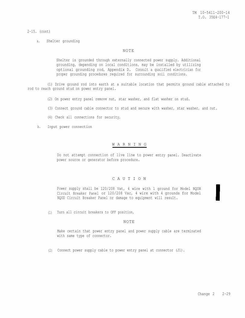
a. Shelter grounding
NOTE
Shelter is grounded through externally connected power supply. Additionalgrounding, depending on local conditions, may be installed by utilizingoptional grounding rod, Appendix D. Consult a qualified electrician forproper grounding procedures required for surrounding soil conditions.
(1) Drive ground rod into earth at a suitable location that permits ground cable attached torod to reach ground stud on power entry panel.
(2) On power entry panel remove nut, star washer, and flat washer on stud.
(3) Connect ground cable connector to stud and secure with washer, star washer, and nut.
(4) Check all connections for security,
b. Input power connection
W A R N I N G
(1)
(2)
Do not attempt connection of live line to powerpower source or generator before procedure.
Power supply shall beCircuit Breaker Panel
C A U T I O N
entry panel. Deactivate
120/208 Vat, 4 wire with 1 ground for Model NQOBor 120/208 Vac, 4 wire with 4 grounds for Model
NQOD Circuit Breaker Panel or damage to equipment will result.
Turn all circuit breakers to OFF position,
NOTE
Make certain that power entry panel and power supply cable are terminatedwith same type of connector.
Connect power supply cable to power entry panel at connector (J1).
Change 2 2-29
TM 10-5411-200-14T.O. 35E4-177-1
2-15. (cont)
(3) Turn MAIN circuit breaker to ON position and observe any unusualconditions.
(4) Turn remaining circuit breakers to ON position one at a time andobserve any-unusual conditions.
c. ECU Connection.
(1) Turn CB1 to OFF position.
(2) Connect ECU supply cable to
(3) Turn CB1 to ON position and
2-16. CLOSING SEQUENCE
NOTE
Four personnel are requiredfollowing procedures.
connector (J2).
observe for any unusual conditions.
to perform the
Make sure hinged floor is clear of items or debrisand floor hinges are clean of sand or dirt.
Make sure top of hinged roof is clear of items,debris, snow, or ice and hinged floor extension isclear of foreign matter, snow or ice.
Do not attempt to lower or remove container liftjacks until after procedures in steps a through qhave been completed.
a. Remove power cord from power entry panel.
b. Remove ECU intake and return panels and replace with closeout panels.
c. Remove hinged roof area ceiling lights and receptacles from expandedsection and return to their stowage position.
d. Remove and stow latch plates in equipment container.
2-30 CHANGE 2
TM 10-5411-200-14T.O. 35E4-177-1
2-16. (cont)
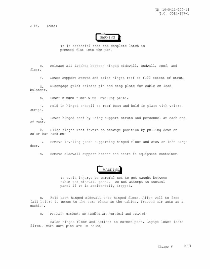
WARNING
It is essential that the complete latch ispressed flat into the pan.
e. Release all latches between hinged sidewall, endwall, roof, andfloor.
f. Lower support struts and raise hinged roof to full extent of strut.
8. Disengage quick release pin and stop plate for cable on loadbalancer.
h. Lower hinged floor with leveling jacks.
i. Fold in hinged endwall to roof beam and hold in place with velcrostraps.
j. Lower hinged roof by using support struts and personnel at each endof roof.
k. Slide hinged roof inward to stowage position by pulling down onsolar bar handles.
l. Remove leveling jacks supporting hinged floor and stow on left cargodoor.
m. Remove sidewall support braces and store in equipment container.
WARNING
To avoid injury, be careful not to get caught betweencable and sidewall panel. Do not attempt to controlpanel if It is accidentally dropped.
n. Fold down hinged sidewall onto hinged floor. Allow wall to freefall before it comes to the same plane as the cables. Trapped air acts as acushion.
o. Position camlocks so handles are vertical and outward.
first.Raise hinged floor and camlock to corner post. Engage lower locks
Make sure pins are in holes,
Change 6 2-31
TM 10-5411-200-14T.O. 35E4-177-1
2-16. (cont)
NOTE
If hinged floor and corner post bind, relevel shelter.
q. Close cargo doors.
r. Remove container lift jacks and stow on personnel and right cargodoors.
NOTE
If it is intended to use a dollyset to move shelter,place pieces of 4x4 lumber under the frame and clearof the ISO fittings to facilitate mounting of thedollyset.
s. Stow power cable inside shelter.
t. Check security of shelter. Quick release pins must be inserted instop plates on load balancer. Place padlocks on outside door handles.
Section IV. OPERATION UNDER USUAL CONDITIONS
NOTEIf equipment fails to operate, refer to trouble-shooting procedures in Chapter 3.
2-17. OPERATING INSTRUCTIONS. Due to the limited operating capability ofshelter, operating instructions are limited to operation of circuit breakersand switches for the purpose of providing power to lights, outlets, andexternally connected environmental control unit (ECU), if installed.Expanding the shelter and closing the shelter includes maintaining the shelterwhen performing any PMCS exercise “During” functions.
2-32
TM 10-5411-200-14T.O. 35E4-177-1
Section V. OPERATION UNDER UNUSUAL CONDITIONS
2-18. GENERAL . This section provides instructions for operation of theshelter in unusual weather conditions. Operation during blackout conditionsis also provided.
2-19. OPERATION IN RAIN AND/OR MUD
a. Provide adequate drainage ditch to prevent standing water aroundshelter area.
b. Check leveling jacks frequently for sinking; level shelter as re-quired by adjusting container lift jacks.
c. Close and secure all doors in shelter.
d. Check seals for proper placement and compression.
2-20. OPERATION IN SNOW, ICE OR EXTREME COLD
W A R N I N G
In extreme cold, do not touch metal parts with barehands. Severe skin damage may result.
a. Remove snow routinely and prior to folding roof with a soft bristlebrush, broom, or equivalent.
b. Remove ice from shelter before lowering hinged panels.
c. Insure ECU is properly connected to shelter.
d. Keep all doors and vents closed.
NOTE
Fluorescent lights have a delay time in coming onat temperatures of 0°F and below.
2-33
TM 10-5411-200-14T.O. 35E4-177-1
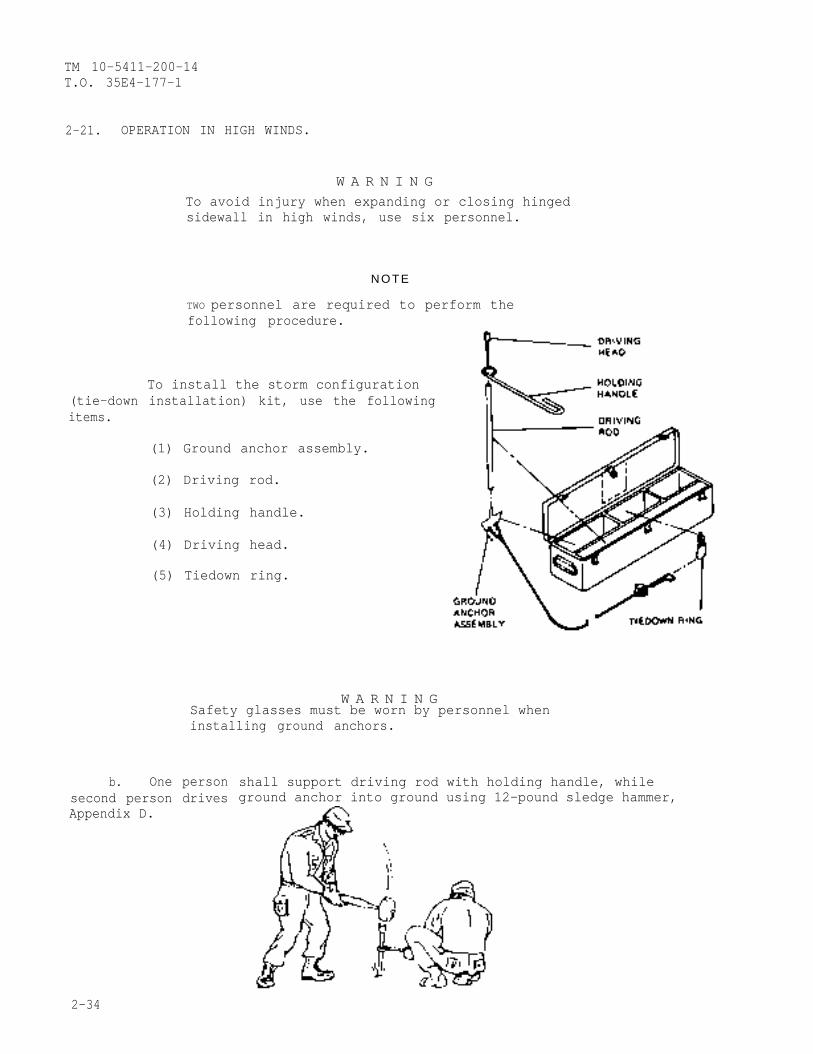
2-21. OPERATION IN HIGH WINDS.
W A R N I N GTo avoid injury when expanding or closing hingedsidewall in high winds, use six personnel.
N O T E
TWO personnel are required to perform thefollowing procedure.
To install the storm configuration(tie-down installation) kit, use the followingitems.
(1) Ground anchor assembly.
(2) Driving rod.
(3) Holding handle.
(4) Driving head.
(5) Tiedown ring.
W A R N I N GSafety glasses must be worn by personnel wheninstalling ground anchors.
b. One personsecond person drivesAppendix D.
shall support driving rod with holding handle, whileground anchor into ground using 12-pound sledge hammer,
2-34
TM 10-5411-200-14T.O. 35E4-177-1
2-21. (cont)
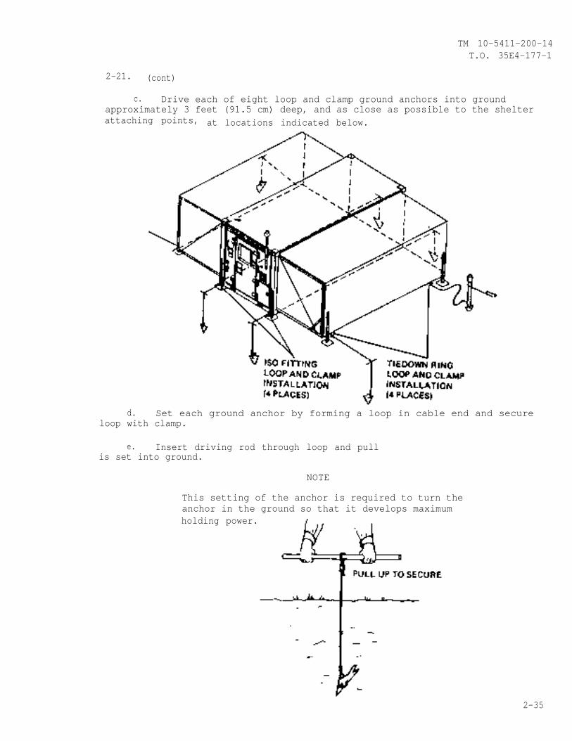
c. Drive each of eight loop and clamp ground anchors into groundapproximately 3 feet (91.5 cm) deep, and as close as possible to the shelterattaching points, at locations indicated below.
d. Set each ground anchor by forming a loop in cable end and secureloop with clamp.
e. Insert driving rod through loop and pullis set into ground.
NOTE
This setting of the anchor is required to turn theanchor in the ground so that it develops maximumholding power.
2-35
TM 10-5411-200-14T.O. 35E4-177-1
2-21. (cont)
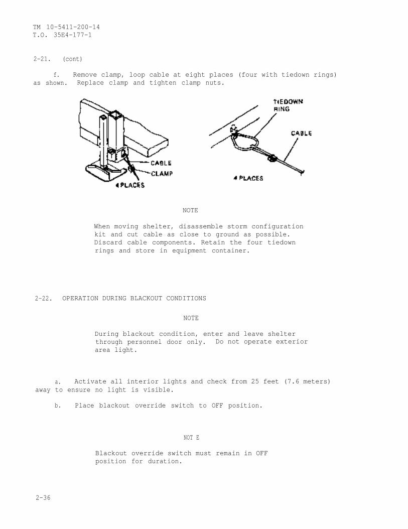
f. Remove clamp, loop cable at eight places (four with tiedown rings)as shown. Replace clamp and tighten clamp nuts.
NOTE
When moving shelter, disassemble storm configurationkit and cut cable as close to ground as possible.Discard cable components. Retain the four tiedownrings and store in equipment container.
2-22. OPERATION DURING BLACKOUT CONDITIONS
NOTE
During blackout condition, enter and leave shelterthrough personnel door only. Do not operate exteriorarea light.
a. Activate all interior lights and check from 25 feet (7.6 meters)away to ensure no light is visible.
b. Place blackout override switch to OFF position.
NOT E
Blackout override switch must remain in OFFposition for duration.
2-36
TM 10-5411-200-14T.O. 35E4-177-1
CHAPTER 3
OPERATOR MAINTENANCE INSTRUCTIONS
Section I. TROUBLESHOOTING PROCEDURES
3-1. GENERAL . This section contains operator troubleshooting information forlocating and correcting common malfunctions which may develop in shelter.
W A R N I N G
HIGH VOLTAGE
exists in the electrical system of
DEATH ON CONTACT
may result if personnel fail to observe
a. Paragraph 3-2 lists common malfunctions
this equipment
safety precautions.
which you may find duringoperation or maintenance of shelter electrical system or components. Youshould perform inspections and corrective actions in order listed.
b. All. malfunctions that may occur and all inspections and correctiveactions may not be listed. If a malfunction is riot listed or is not correctedby corrective action, notify your supervisor.
c. When troubleshooting operation of shelter electrical system, allswitches and circuit breakers shall be placed in OFF positions with powerconnected.
d. The operator is limited to setting circuit breakers (ON/OFF),setting light assemblies in place, and replacing light bulbs.
3-2. OPERATOR TROUBLESHOOTING
MALFUNCTIONTEST OR INSPECTION
CORRECTIVE ACTION
1. NO POWER DISTRIBUTION TO SHELTER.
Step 1. Check that outside power is properly connected to serviceentrance connector on power entry panel, and check generalcondition of cable and connectors.
a. Make proper power connection.
b. Check for defective cable or connectors.
3-1

TM 10-5411-200-14T.O. 35E4-177-1
3-2. (cont)
MALFUNCTIONTEST OR INSPECTION
CORRECTIVE ACTION
Step 2. Check and reset main circuit breaker, and check outsidepower.
Notify organizational maintenance.
2. INCANDESCENT LIGHT FAILS TO COME ON.
Step 1. Check and reset circuit breaker.
Step 2. Check visually for burned out incandescent bulb.
Change bulb. (Refer to paragraph 4-10.)
Step 3. Check operation of incandescent light switch and blackoutoverride switch.
Notify organizational maintenance.
WARNING
In the event of lamp breakage, care must be taken inremoval of broken glass fragments and white phosphorousdust that may be dispersed within fixture. Inhalationof phosphorous dust could cause serious injury.
3. ALL FIXED ROOF AREA AND HINGED ROOF AREA CEILING LIGHTS FAIL TO COME ON.
Step 1. Check operation of fluorescent light switch and blackoutoverride switch.
Step 2. Check and reset circuit breaker.
Notify organizational maintenance.
4. ONE OR MORE HINGED ROOF AREA CEILING LIGHTS FAIL TO COME ON.
Step 1. Check to see if associated flexible cable connector isproperly plugged in.
Make proper connection.
Step 2. Check associated flexible cable and connectors fordefects.
Notify organizational maintenance.
3-2
TM 10-5411-200-14T.O. 35E4-177-1
3-2. (cont)
MALFUNCTIONTEST OR INSPECTION
CORRECTIVE ACTION
5.
6.
7.
8.
9.
Step 3. Check visually for burned out fluorescent lamps.
a. Unplug flexible cable connector and replacelamp. (Refer to paragraph 3-5.)
b. Reconnect flexible cable connector.
ONE OR MORE FIXED ROOF AREA CEILING LIGHTS FAIL TO COME ON.
Check visually for burned out fluorescent lamps.
a. Turn off appropriate circuit breaker and replacelamp. (Refer to paragraph 4-12.)
b. Turn on appropriate circuit breaker.
NO POWER AT ONE OR MORE INTERIOR UTILITY OUTLETS.
Check and reset associated circuit breakers.
Notify organizational maintenance.
NO POWER AT ONE OR BOTH EXTERIOR UTILITY OUTLETS.
Check and reset circuit breaker.
Notify organizational maintenance.
AREA LIGHT FAILS TO COME ON.
Step 1. Check and reset circuit breaker.
Step 2. Check visually for burned out bulb.
Change bulb.
Notify organizational maintenance.
NO POWER AT HEATER/AC SUPPLY.
Step 1. Check that outside power is properly connected to serviceentrance connector on power entry panel, and check generalcondition of cable and connectors.
a. Make proper power connection.
b. Check for defective cable or connectors.
Step 2. Check and reset circuit breakers.
Notify organizational maintenance,
3-3
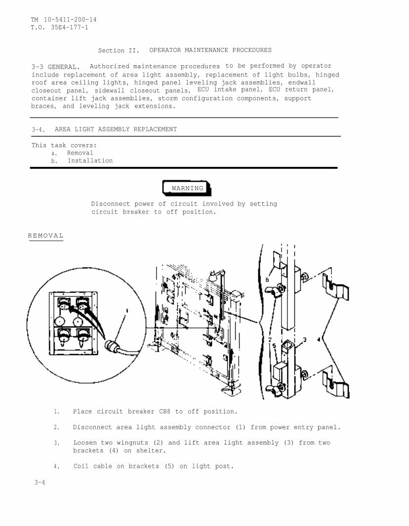
TM 10-5411-200-14T.O. 35E4-177-1
Section II. OPERATOR MAINTENANCE PROCEDURES
3-3 GENERAL. Authorized maintenance procedures to be performed by operatorinclude replacement of area light assembly, replacement of light bulbs, hingedroof area ceiling lights, hinged panel leveling jack assemblies, endwallcloseout panel, sidewall closeout panels, ECU intake panel, ECU return panel,container lift jack assemblies, storm configuration components, supportbraces, and leveling jack extensions.
3-4. AREA LIGHT ASSEMBLY REPLACEMENT
This task covers:a. Removalb. Installation
WARNING
Disconnect power of circuit involved by settingcircuit breaker to off position.
REMOVAL
1. Place circuit breaker CB8 to off position.
2. Disconnect area light assembly connector (1) from power entry panel.
3. Loosen two wingnuts (2) and lift area light assembly (3) from twobrackets (4) on shelter.
4. Coil cable on brackets (5) on light post.
3-4
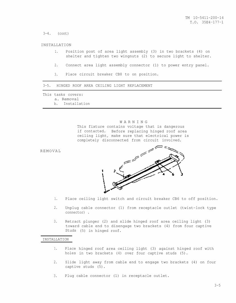
TM 10-5411-200-14T.O. 35E4-177-1
3-4. (cont)
INSTALLATION
1. Position post of area light assembly (3) in two brackets (4) onshelter and tighten two wingnuts (2) to secure light to shelter.
2. Connect area light assembly connector (1) to power entry panel.
3. Place circuit breaker CB8 to on position.
3-5. HINGED ROOF AREA CEILING LIGHT REPLACEMENT
This tasks covers:a. Removalb. Installation
W A R N I N GThis fixture contains voltage that is dangerousif contacted. Before replacing hinged roof areaceiling light, make sure that electrical power iscompletely disconnected from circuit involved.
REMOVAL
1. Place ceiling light switch and circuit breaker CB6 to off position.
2. Unplug cable connector (1) from receptacle outlet (twist-lock typeconnector) .
3. Retract plunger (2) and slide hinged roof area ceiling light (3)toward cable end to disengage two brackets (4) from four captiveStuds
INSTALLATION
1. Placeholes
2. Slide
(5) in hinged roof.
hinged roof area ceiling light (3) against hinged roof within two brackets (4) over four captive studs (5).
light away from cable end to engage two brackets (4) on fourcaptive studs (5).
3. Plug cable connector (1) in receptacle outlet.
3-5
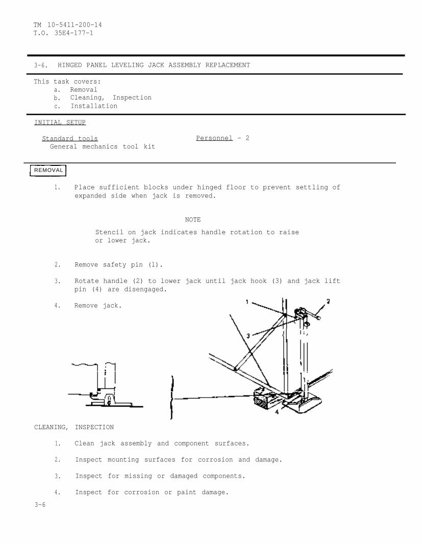
TM 10-5411-200-14T.O. 35E4-177-1
3-6. HINGED PANEL LEVELING JACK ASSEMBLY REPLACEMENT
This task covers:a. Removalb. Cleaning, Inspectionc. Installation
INITIAL SETUP
Standard tools Personnel - 2General mechanics tool kit
REMOVAL
1. Place sufficient blocks under hinged floor to prevent settling ofexpanded side when jack is removed.
NOTE
Stencil on jack indicates handle rotation to raiseor lower jack.
2. Remove safety pin (l).
3. Rotate handle (2) to lower jack until jack hook (3) and jack liftpin (4) are disengaged.
4. Remove jack.
CLEANING, INSPECTION
1. Clean jack assembly and component surfaces.
2. Inspect mounting surfaces for corrosion and damage.
3. Inspect for missing or damaged components.
4. Inspect for corrosion or paint damage.
3-6
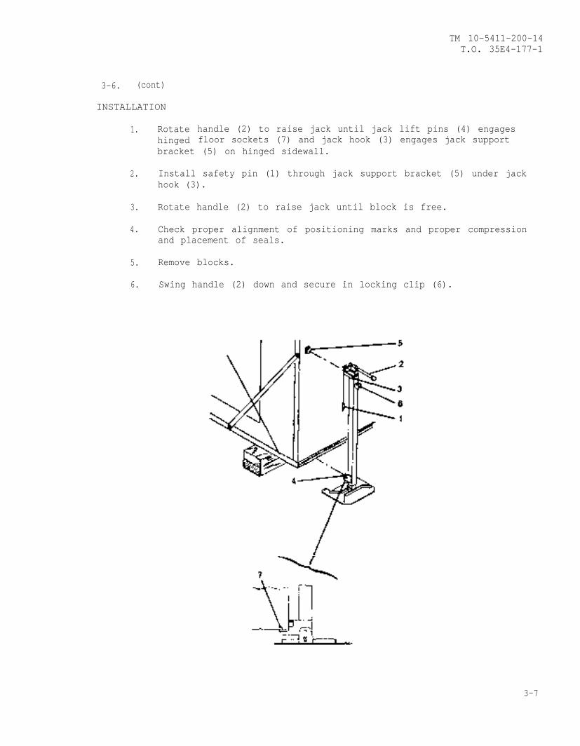
TM 10-5411-200-14T.O. 35E4-177-1
3-6. (cont)
INSTALLATION
1. Rotatehinged
handle (2) to raise jack until jack lift pins (4) engagesfloor sockets (7) and jack hook (3) engages jack support
bracket (5) on hinged sidewall.
2. Install safety pin (1) through jack support bracket (5) under jackhook (3).
3. Rotate handle (2) to raise jack until block is free.
4. Check proper alignment of positioning marks and proper compressionand placement of seals.
5. Remove blocks.
6. Swing handle (2) down and secure in locking clip (6).
3-7

TM 10-5411-200-14T.O. 35E4-177-1
3-7. ENDWALL CLOSEOUT PANEL REPLACEMENT
This task covers:a. Removalb. Installation
INITIAL SETUP
Standard Tools Personnel-2General mechanics tool kit
REMOVAL
WARNING
When hinged floor is in deployed position, do notdisconnect support cable from hinged floor untilstop plates on load balancer (inside shelter) havebeen locked with quick release pins to preventreturn of support cable.
1. Move flexible electrical cable to facilitate removal of endwall
2. Inside shelter, loosen twelve captive screws (1) and remove endwallcloseout panel (2).
INSTALLATION
NOTE
Endwall closeout Panel (2) iS stowed on outsideof hinged sidewall when-not in use.
Position endwall closeout panel (2) against shelter endwall and secure bytightening twelve captive screws (1), placing bottom end in first
3-8 CHANGE 2
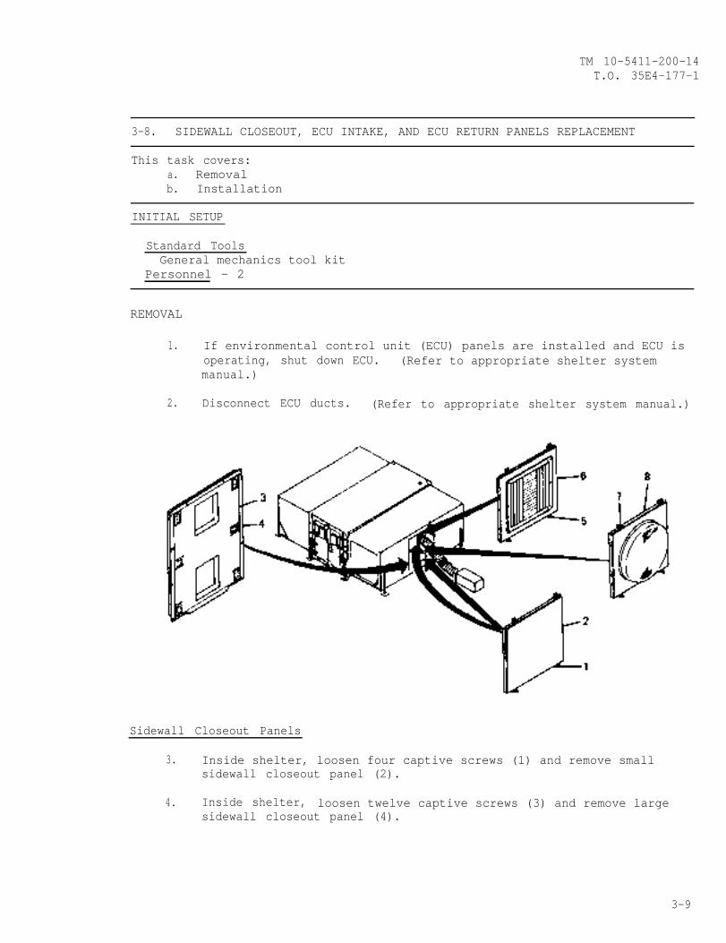
TM 10-5411-200-14T.O. 35E4-177-1
3-8. SIDEWALL CLOSEOUT, ECU INTAKE, AND ECU RETURN PANELS REPLACEMENT
This task covers:a. Removalb. Installation
INITIAL SETUP
Standard ToolsGeneral mechanics tool kit
Personnel - 2
REMOVAL
1. If environmental control unit (ECU) panels are installed and ECU isoperating, shut down ECU. (Refer to appropriate shelter systemmanual.)
2. Disconnect ECU ducts. (Refer to appropriate shelter system manual.)
Sidewall Closeout Panels
3. Inside shelter, loosen four captive screws (1) and remove smallsidewall closeout panel (2).
4. Inside shelter, loosen twelve captive screws (3) and remove largesidewall closeout panel (4).
3-9
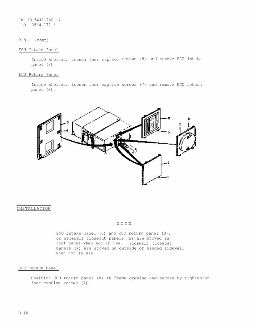
TM 10-5411-200-14T.O. 35E4-177-1
3-8. (cont)
ECU Intake Panel
Inside shelter,panel (6).
ECU Return Panel
Inside shelter,panel (8).
loosen four captive screws (5) and remove ECU intake
loosen four captive screws (7) and remove ECU return
INSTALLATION
N O T E
ECU intake panel (6) and ECU return panel (8),or sidewall closeout panels (2) are stowed inroof panel when not in use. Sidewall closeoutpanels (4) are stowed on outside of hinged sidewallwhen not in use.
ECU Return Panel
Position ECU return panel (8) in frame opening and secure by tighteningfour captive screws (7).
3-10
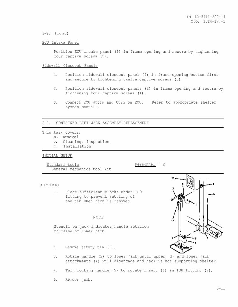
TM 10-5411-200-14T.O. 35E4-177-1
3-8. (cont)
ECU Intake Panel
Position ECU intake panel (6) in frame opening and secure by tighteningfour captive screws (5).
Sidewall Closeout Panels
1. Position sidewall closeout panel (4) in frame opening bottom firstand secure by tightening twelve captive screws (3).
2. Position sidewall closeout panels (2) in frame opening and secure bytightening four captive screws (1).
3. Connect ECU ducts and turn on ECU. (Refer to appropriate sheltersystem manual.)
3-9. CONTAINER LIFT JACK ASSEMBLY REPLACEMENT
This task covers:a. Removalb. Cleaning, Inspectionc. Installation
INITIAL SETUP
Standard toolsGeneral mechanics tool kit
Personnel - 2
REMOVAL
1. Place sufficient blocks under IS0fitting to prevent settling ofshelter when jack is removed.
NOTE
Stencil on jack indicates handle rotationto raise or lower jack.
2. . Remove safety pin (1).
3. Rotate handle (2) to lower jack until upper (3) and lower jackattachments (4) will disengage and jack is not supporting shelter.
4. Turn locking handle (5) to rotate insert (6) in IS0 fitting (7),
5. Remove jack.
3-11
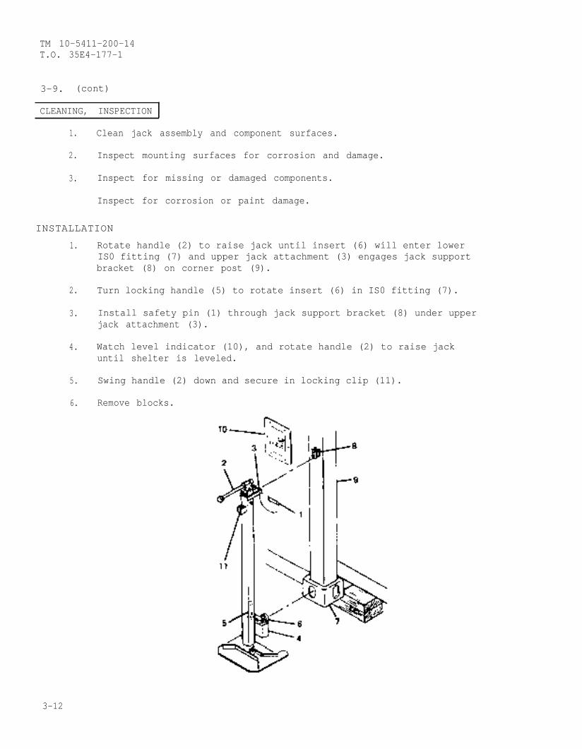
TM 10-5411-200-14T.O. 35E4-177-1
3-9. (cont)
CLEANING, INSPECTION
1. Clean jack assembly and component surfaces.
2. Inspect mounting surfaces for corrosion and damage.
3. Inspect for missing or damaged components.
Inspect for corrosion or paint damage.
INSTALLATION
1.
2.
3.
4.
5.
6.
Rotate handle (2) to raise jack until insert (6) will enter lowerIS0 fitting (7) and upper jack attachment (3) engages jack supportbracket (8) on corner post (9).
Turn locking handle (5) to rotate insert (6) in IS0 fitting (7).
Install safety pin (1) through jack support bracket (8) under upperjack attachment (3).
Watch level indicator (10), and rotate handle (2) to raise jackuntil shelter is leveled.
Swing handle (2) down and secure in locking clip (11).
Remove blocks.
3-12
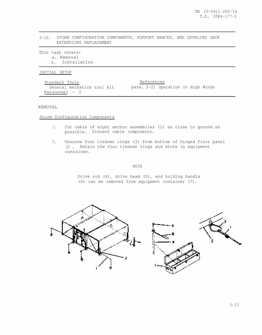
TM 10-5411-200-14T.O. 35E4-177-1
3-10. STORM CONFIGURATION COMPONENTS, SUPPORT BRACES, AND LEVELING JACKEXTENSIONS REPLACEMENT
This task covers:a. Removalb. Installation
INITIAL SETUP
Standard Tools ReferencesGeneral mechanics tool kit para. 2-21 Operation in High Winds
Personnel - 2
REMOVAL
Storm Configuration Components
1. Cut cable of eight anchor assemblies (1) as close to ground aspossible. Discard cable components.
2. Unscrew four tiedown rings (3) from bottom of hinged floor panel(2) . Retain the four tiedown rings and store in equipmentcontainer.
NOTE
Drive rod (4), drive head (5), and holding handle(6) can be removed from equipment container (7).
3-13
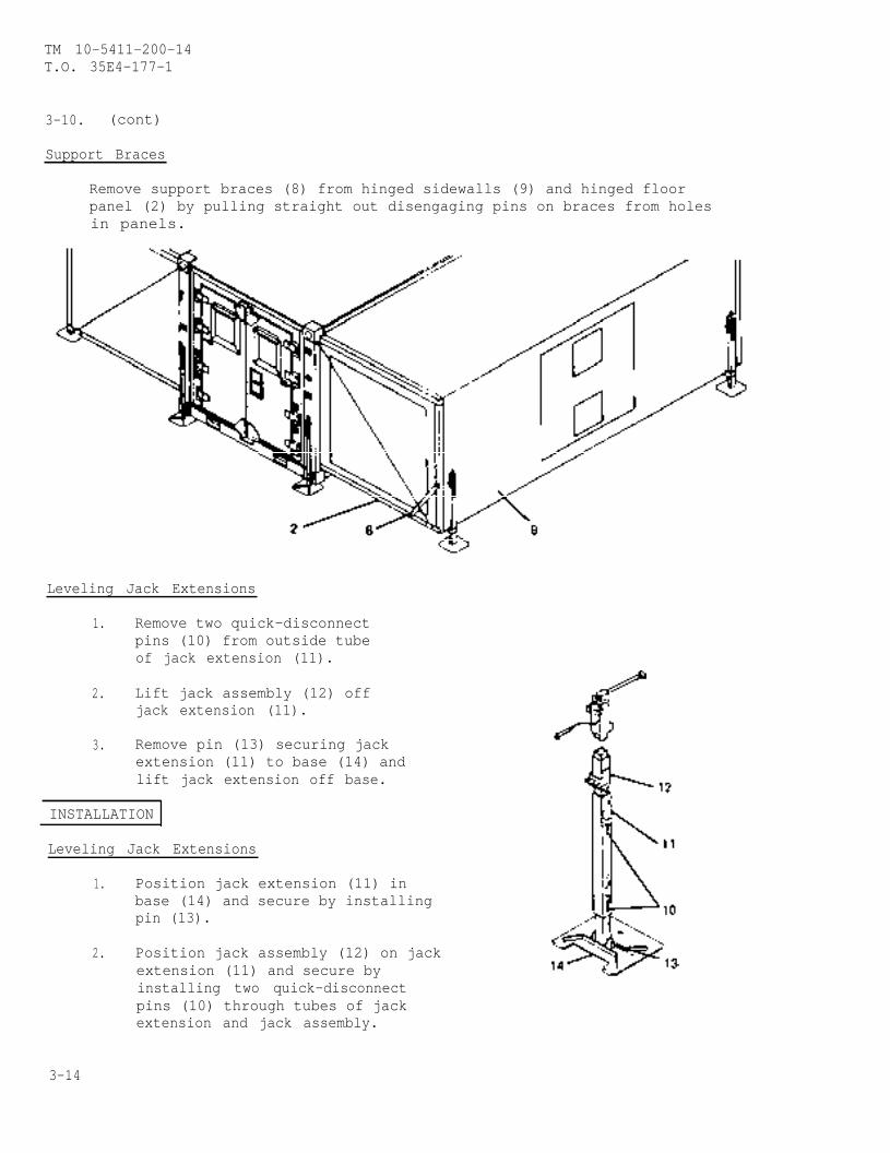
TM 10-5411-200-14T.O. 35E4-177-1
3-10. (cont)
Support Braces
Remove support braces (8) from hinged sidewalls (9) and hinged floorpanel (2) by pulling straight out disengaging pins on braces from holesin panels.
Leveling Jack Extensions
1. Remove two quick-disconnectpins (10) from outside tubeof jack extension (11).
2. Lift jack assembly (12) offjack extension (11).
3. Remove pin (13) securing jackextension (11) to base (14) andlift jack extension off base.
INSTALLATION
Leveling Jack Extensions
1. Position jack extension (11) inbase (14) and secure by installingpin (13).
2. Position jack assembly (12) on jackextension (11) and secure byinstalling two quick-disconnectpins (10) through tubes of jackextension and jack assembly.
3-14
TM 10-5411-200-14T.O. 35E4-177-1
3-10. (cont)
Support Braces
Install support braces (8) in hinged sidewall (9) and hinged floor panel(2) by pushing straight in engaging pins on braces in holes on panels.
Storm Configuration Components
Refer to paragraph 2-21 for installation of storm configurationcomponents.
3-15/(3-16 blank)

TM 1O-5411-2OO-14T.O. 35E4-177-1
CHAPTER 4
ORGANIZATIONAL MAINTENANCE INSTRUCTIONS
Section I. REPAIR PARTS, SPECIAL TOOLS, TMDE, AND SUPPORT EQUIPMENT
4-1. COMMON TOOLS AND EQUIPMENT.
a. Appendix B, Section III contains the authorized common tools.
b. For authorized equipment refer to Modified Table of Organization andEquipment (MTOE) applicable to your unit.
4-2. SPECIAL TOOLS, TMDE, AND SUPPORT EQUIPMENT.
a. A special tool, hand blind riveter, Appendix B, Item 2 is used forshelter skin repair and general riveting utilizing blind rivets.
b. Installation tools, Appendix B, Items 3 and 9 are used forinstallation of captive screws.
c. Portable electric router, Appendix B, Item 15 is used to cut outpanels. Use tripod base heat lamp, Appendix B, Item 16 during panel repair.
d. Snap ring pliers, Appendix B, Item 10, is used to remove and installretaining rings on closeout panels.
e. Fastener header, Appendix B, Item 7 or 8 and box end or adjustablewrench, Appendix B, Item 11 are used to install non-potted inserts.
f. Multimeter, Appendix B, Item 4, is used to perform allcontinuity/voltage tests on shelter. Electric tool kit, Appendix B, Item 5 isused to repair wiring.
g. Use portable electric drill, Appendix B, Item 6 to drive hinge pins.
h. Blind bolt removal tool kit, Appendix B, Item 13, is used to removerivets on hinge edge members of floor panel.
i. Installation tool, Appendix B, Item 14 is used to install rivets onhinge edge members of floor panel.
i Use crimping tool, Appendix B, Item 12, to attach wires toreceptacle pins on power entry panel,
4-3. REPAIR PARTS. Repair parts covering organizational maintenance for thisshelter are listed and illustrated in TM 1O-5411-2OO-24P.
4-1
TM 10-5411-200-14T.O. 35E4-177-1
Section II. TROUBLESHOOTING PROCEDURES
4-4. GENERAL. This Section contains organizational troubleshootinginformation for locating and correcting common malfunctions which may developin shelter electrical system.
WARNING
The shelter contains voltages that are dangerous ifcontacted. Take appropriate precautions when trouble-shooting. Before performing continuity checks orreplacing electrical components, make sure thatelectrical power is disconnected from circuit involved.
4-5. TROUBLESHOOTING. Each malfunction for an individual component or unitis listed in paragraph 4-6. The malfunction is followed by a list of tests orinspections which help to determine probable causes and corrective actions totake. The tests or inspections and corrective actions are to be performed inthe order listed in the table. All malfunctions that may occur and all testsor inspections and corrective actions may not be listed. If a malfunction isnot listed or is not corrected by corrective action, notify your supervisor.Unless otherwise noted, when troubleshooting operation of shelter electricalsystem, all switches and circuit breakers shall be placed in operatingpositions with power connected. The electrical system schematic diagram(4-45) and wire list (4-46) are located at the end of Chapter 4, Section III.
4-6. ORGANIZATIONAL MAINTENANCE TROUBLESHOOTING
MALFUNCTIONTEST OR INSPECTION
CORRECTIVE ACTION
1. NO POWER DISTRIBUTION TO SHELTER.
Step 1. Check that outside power is properly connected to serviceentrance on power entry panel, check general condition ofcable and connectors. Test operation of power entrypanel.
a. Replace defective wiring (paragraph 4-8).
b. Replace defective connectors (paragraph 4-8).
Step 2. Test operation of main circuit breaker and wiring(paragraph 4-7).
a. Replace defective wiring (paragraph 4-7).
b. Replace defective circuit breaker (paragraph 4-7).
4-2
TM 10-5411-200-14T.O. 35E4-177-1
4-6. (cont)
MALFUNCTIONTEST OR INSPECTION
CORRECTIVE ACTION
2. INCANDESCENT LIGHT FAILS TO COME ON.
Step 1. Check visually for burned out bulb.
Replace bulb (paragraph 4-10).
Step 2. Test operation of incandescent light switch (S3), blackoutoverride switch (S1) and wiring (paragraph 4-10).
a. Replace defective wiring (paragraph 4-10).
b. Replace defective switch (paragraph 4-10).
Step 3. Check and reset circuit breaker CB6.
Replace defective circuit breaker (paragraph 4-7).
3. ALL FLUORESCENT LIGHTS FAIL TO COME ON.
step 1. Check and reset circuit breaker CB6.
Replace defective circuit breaker (paragraph 4-7).
Step 2. Test operation of fluorescent light switch (S4), blackoutoverride switch (S1), and wiring (paragraph 4-7).
a. Replace defective wiring (paragraph 4-7).
b. Replace defective switch (paragraph 4-7).
4. ONE OR MORE FLUORESCENT LIGHTS IN THE EXPANDED SECTIONS FAIL TO COME ON.
Step 1.
Step 2.
Step 3.
Check visually for burned out fluorescent lamps.
Replace lamp, (paragraph 4-12).
Check associated flexible cable connectors for properconnection or defects.
Make proper connection or replace damaged connector orflexible cable (paragraph 4-11).
Test operation of fluorescent light fixture and wiring(paragraph 4-11).
a. Replace defective wiring (paragraph 4-11).
b. Replace defective light fixture (paragraph 3-5).
4-3
TM 10-5411-200-14T.O. 35E4-177-1
4-6. (cont)
MALFUNCTIONTEST OR INSPECTION
CORRECTIVE ACTION
5. ONE OR MORE FLUORESCENT LIGHTS IN THE FIXED SECTION FAIL TO COME ON.
Step 1. Check visually for burned out fluorescent lamps.
Replace lamp, (paragraph 4-12).
Step 2. Test operation of fluorescent light fixture and wiring(paragraph 4-12).
a. Replace defective wiring (paragraph 4-12).
b. Replace defective light fixture (paragraph 4-12).
WARNING
In the event of lamp breakage, care must be taken inremoval of broken glass fragments and white phosphorousdust that may be dispersed within fixture. Inhalationof phosphorous dust could cause dangerous injury.
6. NO POWER AT ONE OR MORE UTILITY OUTLETS IN THE EXPANDED SECTIONS.
Step 1. Check and reset associated circuit breaker CB3, CB5, CB7.
Replace defective circuit breaker (paragraph 4-7).
Step 2. Test operation of utility outlet and wiring (paragraph4-13) .
a. Replace defective wiring (paragraph 4-13).
b. Replace defective outlet (paragraph 4-13).
7. NO POWER AT ECU SUPPLY CONNECTOR.
Step 1. Check and reset circuit breaker CB1.
Replace defective circuit breaker (paragraph 4-7).
Step 2. Test operation of connector and wiring (paragraph(4-8).
a. Replace defective wiring (paragraph 4-8).
b. Replace defective connector (paragraph 4-8).
4-4
TM 10-5411-200-14T.O. 35E4-177-1
4-6. (cont)
MALFUNCTIONTEST OR INSPECTION
CORRECTIVE ACTION—
8. NO POWER AT ONE OR BOTH EXTERIOR UTILITY OUTLETS.
Step 1. Check and reset circuit breaker CB8.
Replace defective circuit breaker (paragraph 4-7).
Step 2. Test operation of associated exterior utility outlet andwiring (paragraph 4-13).
a. Replace defective
b. Replace defective
Section III. ORGANIZATIONAL
wiring (paragraph 4-13).
outlet (paragraph 4-13).
MAINTENANCE PROCEDURES
This section contains the following maintenance procedures for the shelter.
LIST OF FUNCTIONS
Function Function Ref.No.
1
2
345678910
Function (paragraph)
Circuit Breaker Panel Assembly Testing, Replacement andRepair (Models NQOB and NQOD)
Replacement of Obsolete NQOB Circuit Breaker Panel WithNew NQOD Circuit Breaker Panel
Power Entry Panel Assembly Testing, Replacement and RepairArea Light Assembly Testing and RepairIncandescent Light Assembly Testing, Replacement and RepairHinged Roof Area Ceiling Light Testing and RepairFixed Roof Area Ceiling Light Testing, Replacement and RepairReceptacle Outlets Testing, Replacement, and RepairWall Switches ReplacementBlackout Switch Replacement, Repair, and AdjustmentWiring Testing, Replacement, and RepairPersonnel and Right Cargo Door Replacement, Repair, andAlignment
Left Cargo Door Replacement, Repair, and AlignmentHinged Panel Leveling Jack Assemblies Service and RepairHinged Roof Panels Service, Replacement, Repair, and AlignmentHinged Endwall Replacement and RepairHinged Sidewalls Replacement and RepairHinged Floor Panel Replacement and Repair
4-7
4-7.1
4-94-8
4-104-114-124-134-144-154-161 1
1 2
1 31 41 51 61 71 8
4-174-184-194-204-214-224-23
CHANGE 2 4-5
TM 10-5411-200-14T.O. 35E4-177-1
LIST OF FUNCTIONS (CONT)
FunctionN o . Function
29
202122232425262728
30313233343536373839
19 Container Lift Jack Assemblies Service and RepairPersonnel Door End Endwall Panel Replacement and RepairCargo Door End Endwall Panel Replacement and RepairRoof Panel Assembly RepairFloor Panel RepairCamlock and Latch Cam Handle Replacement and RepairEquipment Container Replacement and RepairDrying Water-Soaked Areas In PanelsBlind Rivet Removal and InstallationRepair of Small Dent or DepressionRepair of Depression or Small PunctureRepair of Puncture With Minimal Damage to CoreRepair of Puncture With Core FractureRepair of Damage With Extended CracksRepair of Puncture Through One Skin and CoreRepair of Puncture Through Both Skins and CoreShelter Body Seals ReplacementThreaded Inserts ReplacementCaulking Repair AreasPaint RefinishingDecal Removal/Replacement
Function Ref.(paragraph)
4-244-254-264-274-284-294-304-314-324-334-344-354-364-374-384-394-404-414-424-434-44
4-7. CIRCUIT BREAKER PANEL ASSEMBLY TESTING, REPLACEMENT, AND REPAIR (MODELSNQOB AND NQOD)
a.
This task covers:
Testing d. Repairb. Removal e. Installationc. Cleaning, Inspection
INITIAL SETUP
Standard TOOls Personnel RequiredGeneral Mechanics Tool Kit Electrician
Test EquipmentMultimeter, Appendix B, Item 4Electrical Tool Kit, Appendix B,
Item 5
4-6 CHANGE 2

TM 10-5411-200-14T.O. 35E4-177-1
4-7. (cont)
TESTING
WARNING
Disconnect electrical power from shelter beforetesting. Failure to observe this warning may causedeath or serious injury to personnel.
1. Tag and disconnect shelter electrical power.
2. Set all circuit breakers and switches to OFF position.
NOTE
This procedure covers the obsolete NQOB circuitbreaker panel and the new NQOD circuit breakerpanel . These units are distinguishable by thenameplates (9) attached to the panel boards.
CHANGE 2 4-7
TM 10-5411-200-14T.O. 35E4-177-1
4-7. (cont)
3. Open circuit breaker panel door (1) on both models.
4. Loosen four captive screws (2) and move clamp fingers (3) to OPENposition on model NQOB.
5. Lift circuit breaker panel board (5) on modelNQOB.
6. Remove four screws (6) and lift panel board (5) fromcircuit breaker box (8) on both models.
NOTE
Once the panelboards are removed, all furtherprocedures are identical for both models.
7. Reconnect site power.
8. Set main circuit breaker to ON position.
pop to OFF position.
10. Disconnect site power.
11. Using multimeter, checkswitches, and wiring.
9. Set branch circuit breakers to ON position and observe if any breakers
for continuity of circuit breakers, light
12. If no continuity is present, replace defective circuit breaker, lightswitch, or panel wiring. (Refer to paragraph 5-2)
REMOVAL
WARNING
Disconnect electrical power from shelter beforeremoving components. Failure to observe thiswarning may cause death or serious injury topersonnel.
1. Tag and disconnect shelter electrical power.
2. Set all circuit breakers and switches to OFF position.
4-8 CHANGE 2
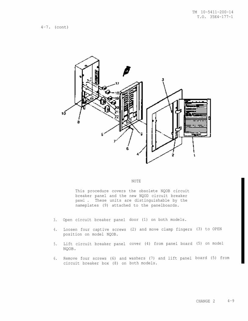
4-7. (cont)
TM 10-5411-200-14T.O. 35E4-177-1
3.
4.
5.
6.
NOTE
This procedure covers the obsolete NQOB circuitbreaker panel and the new NQOD circuit breakerpanel . These units are distinguishable by thenameplates (9) attached to the panelboards.
Open circuit breaker panel
Loosen four captive screwsposition on model NQOB.
Lift circuit breaker panelNQOB.
Remove four screws (6) andcircuit breaker box (8) on
door (1) on both models.
(2) and move clamp fingers
cover (4) from panel board
washers (7) and lift panelboth models.
(3) to OPEN
(5) on model
board (5) from
CHANGE 2 4-9
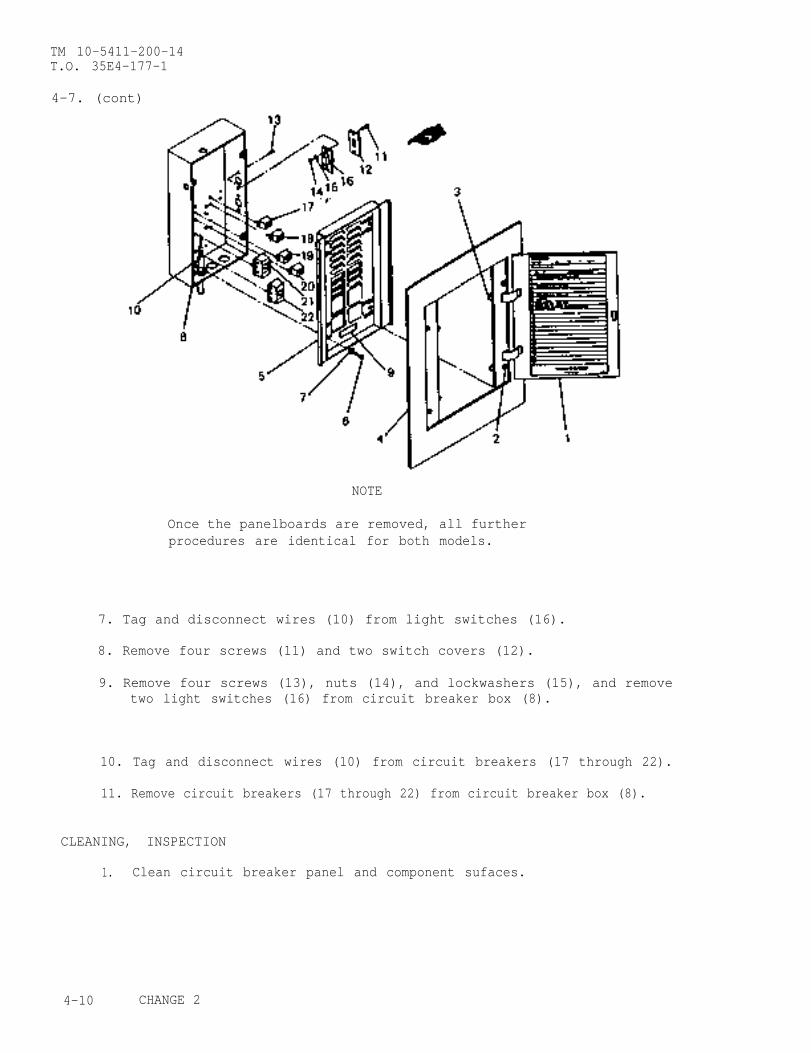
TM 10-5411-200-14T.O. 35E4-177-1
4-7. (cont)
NOTE
Once the panelboards are removed, all furtherprocedures are identical for both models.
7. Tag and disconnect wires (10) from light switches (16).
8. Remove four screws (11) and two switch covers (12).
9. Remove four screws (13), nuts (14), and lockwashers (15), and removetwo light switches (16) from circuit breaker box (8).
10. Tag and disconnect wires (10) from circuit breakers (17 through 22).
11. Remove circuit breakers (17 through 22) from circuit breaker box (8).
CLEANING, INSPECTION
1. Clean circuit breaker panel and component sufaces.
4-10 CHANGE 2

TM 10-5411-200-14T.O. 35E4-177-1
4-7. (cont)
NOTE
Do not use water to clean circuit breaker panelassembly.
2. Inspect mounting surfaces for corrosion and damage.
3. Inspect for damaged circuit breakers or light switches.
4. Inspect panel wiring for cracks, tears, burns, or other damage.
REPAIR
1. Replace damaged circuit breakers or light switches.
2. Repair or replace damaged wiring.
INSTALLATION
Circuit B. reaker
Install circuit breakers (17 through 22) in circuit breaker box (8).
Connect wires (10) to circuit breakers (17 through 22).
Light Switches
3. Position two light switches (16) in circuit breaker box (8) and securewith four screws (13), nuts (14), and lockwashers (15).
4. Position two switch covers (12) over light switches (16) and securewith four screws (11).
5. Connect wires (10) to light switches (16).
6. Attach panelboard (5) to circuit breaker box (8) with screws (6) andwashers (7).
7. Place panel cover (4) on model NQOB panelboard (5), move clamp fingers(3) to LOCK position and tighten captive screws (2).
8. Close circuit breaker panel door (l).
CHANGE 2 4-11
TM 10-5411-200-14T.O. 35E4-177-1
4-7.1 REPLACEMENT OF OBSOLETE NQOB CIRCUIT BREAKER PANEL WITH NEW NQOD CIRCUITBREAKER PANEL.
This task covers:
a. Removal d. Assemblyb. Disassemblyc. Installation
INITIAL SETUP
Standard Tools Personnel RequiredGeneral Mechanics Tool Kit Electrician
Test EquipmentBlind Nut Assemblies (4),Appendix E, Item 26
Conduit (P/N 5-4-5061-2)New Circuit Breaker Panel
NQOD (P/N 5-4-3199)
WARNING
Disconnect electrical power from shelter beforedisassembling circuit breaker panel. Failure toobserve this warning may cause death or seriousinjury to personnel.
NOTE
All parts removed from the obsolete NQOB circuitbreaker panel are reusable in the installation ofthe new NQOD circuit breaker panel with thefollowing exceptions: circuit breaker box,panelboard, panel cover, and conduit entering thetop of circuit breaker box. The new NQOD circuitbreaker panel (P/N 5-4-3199) consists of breakerbox and panel cover. The box is prepunched toaccept light switches, wiring entry, and mounts forcircuit breakers.
4-12 CHANGE 2
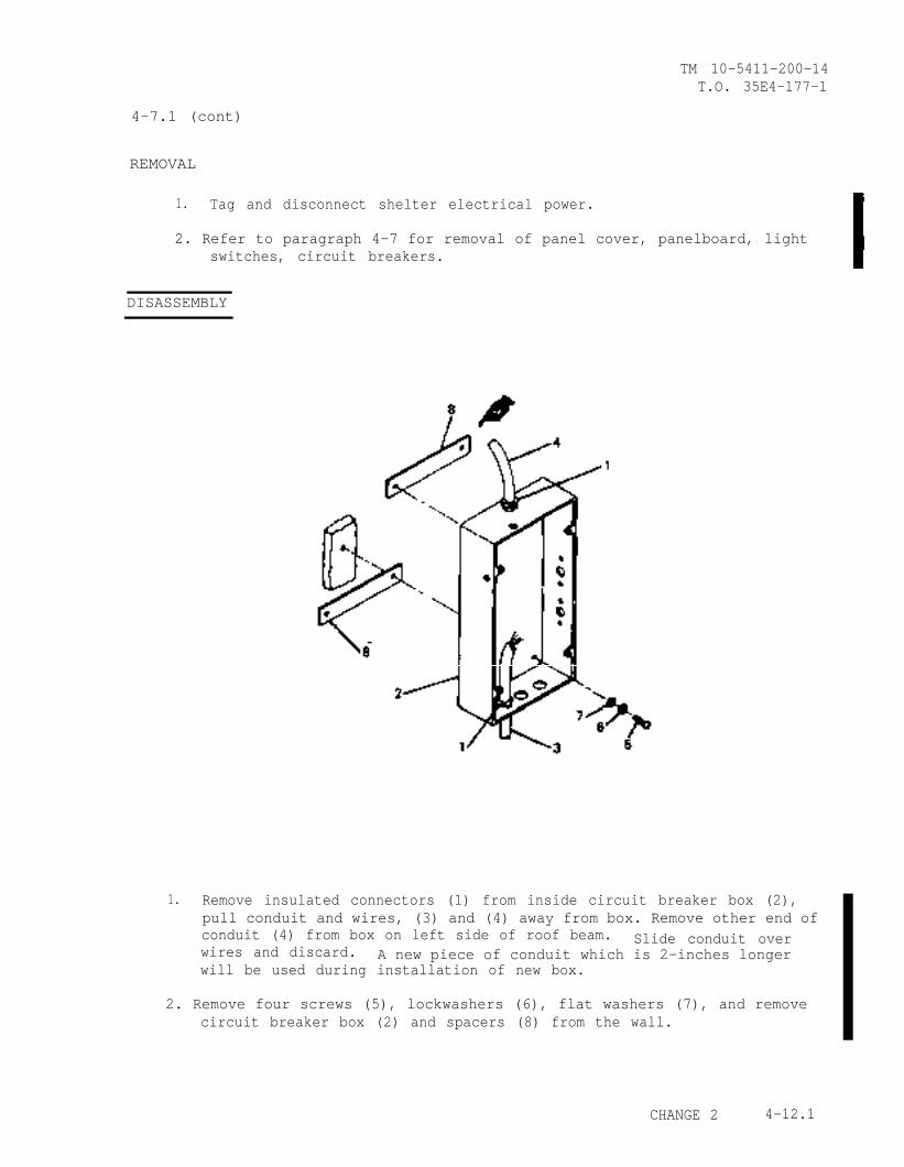
TM 10-5411-200-14T.O. 35E4-177-1
4-7.1 (cont)
REMOVAL
1. Tag and disconnect shelter electrical power.
2. Refer to paragraph 4-7 for removal of panel cover, panelboard, lightswitches, circuit breakers.
DISASSEMBLY
1. Remove insulated connectors (1) from inside circuit breaker box (2),pull conduit and wires, (3) and (4) away from box. Remove other end ofconduit (4) from box on left side of roof beam. Slide conduit overwires and discard. A new piece of conduit which is 2-inches longerwill be used during installation of new box.
2. Remove four screws (5), lockwashers (6), flat washers (7), and removecircuit breaker box (2) and spacers (8) from the wall.
CHANGE 2 4-12.1
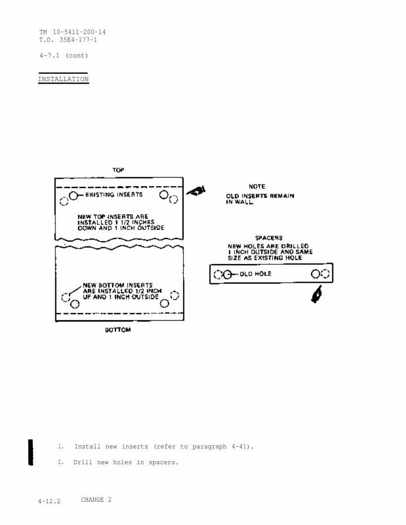
TM 10-5411-200-14T.O. 35E4-177-1
4-7.1 (cont)
INSTALLATION
1. Install new inserts (refer to paragraph 4-41).
2. Drill new holes in spacers.
4-12.2 CHANGE 2
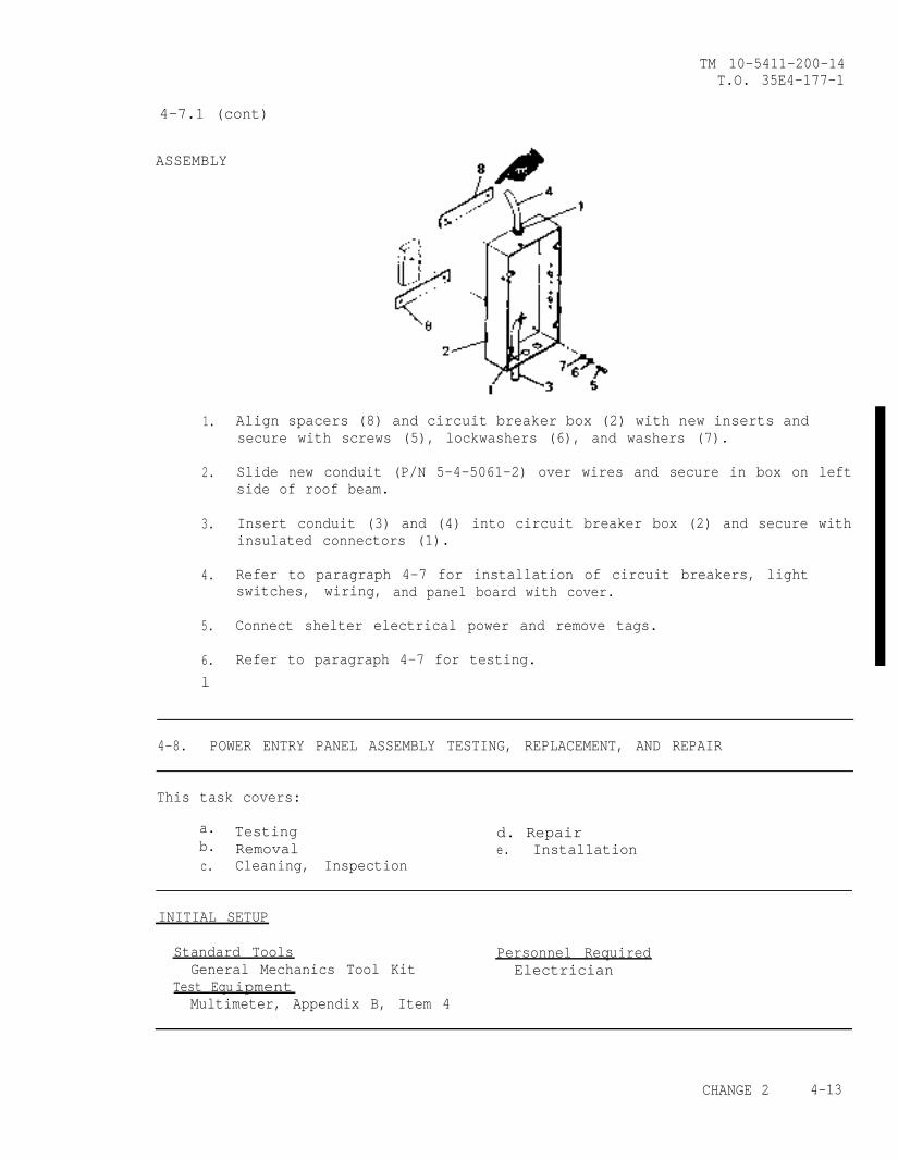
TM 10-5411-200-14T.O. 35E4-177-1
4-7.1 (cont)
ASSEMBLY
1. Align spacers (8) and circuit breaker box (2) with new inserts andsecure with screws (5), lockwashers (6), and washers (7).
2. Slide new conduit (P/N 5-4-5061-2) over wires and secure in box on leftside of roof beam.
3. Insert conduit (3) and (4) into circuit breaker box (2) and secure withinsulated connectors (1).
4. Refer to paragraph 4-7 for installation of circuit breakers, lightswitches, wiring, and panel board with cover.
5. Connect shelter electrical power and remove tags.
6. Refer to paragraph 4-7 for testing.l
4-8. POWER ENTRY PANEL ASSEMBLY TESTING, REPLACEMENT, AND REPAIR
This task covers:
a.b.
Testing d. RepairRemoval e. Installation
c. Cleaning, Inspection
INITIAL SETUP
Standard Tools Personnel RequiredGeneral Mechanics Tool Kit Electrician
Test EquipmentMultimeter, Appendix B, Item 4
CHANGE 2 4-13
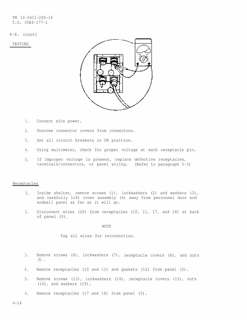
TM 10-5411-200-14T.O. 35E4-177-1
4-8. (cont)
TESTING
1. Connect site power.
2. Unscrew connector covers from connectors.
3. Set all circuit breakers in ON position.
4. Using multimeter, check for proper voltage at each receptacle pin.
5. If Improper voltage is present, replace defective receptacles,terminals/connectors, or panel wiring. (Refer to paragraph 5-3)
Receptacles
10 Inside shelter, remove screws (l), lockwashers (2) and washers (3),and carefully lift cover assembly (4) away from personnel door endendwall panel as far as it will go.
2. Disconnect wires (20) from receptacles (10, 11, 17, and 18) at backof panel (5)0
NOTE
Tag all wires for reconnection.
3. Remove screws (6), lockwashers (7), receptacle covers (8), and nuts(9) .
4. Remove receptacles (10 and 11) and gaskets (12) from panel (5).
5. Remove screws (13), lockwashers (14), receptacle covers (15), nuts(16), and washers (19).
6. Remove receptacles (17 and 18) from panel (5).
4-14
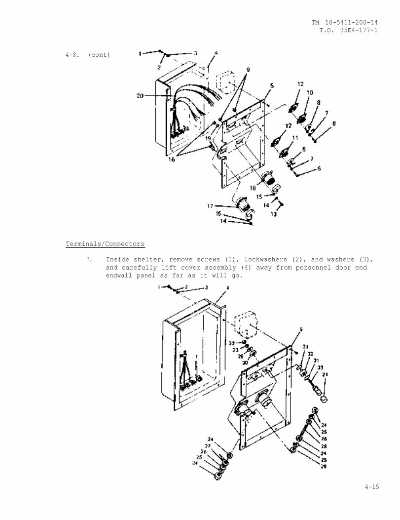
TM 10-5411-200-14T.O. 35E4-177-1
4-8. (cont)
Terminals/Connectors
7. Inside shelter, remove screws (1), lockwashers (2), and washers (3),and carefully lift cover assembly (4) away from personnel door endendwall panel as far as it will go.
4-15
TM 10-5411-200-14T.O. 35E4-177-1
4-8. (cont)
8. Disconnect wires from terminals/connectors at rear of panel (5).
NOTE
Tag all wires for reconnection.
9. Remove rubber cap (21), nut (22), lockwasher (23), brass washer(29), nylon washer (30), two O-rings (31), nylon washer (32), andbinding post body (33) from panel (5).
10. Remove four nuts (24), three lockwashers (25), three washers (26),terminal lug (27), and threaded stud (28) from panel (5).
CLEANING, INSPECTION
1. Clean power entry panel and component surfaces.
2. Inspect mounting surfaces for corrosion and damage.
3. Inspect for damaged receptacles, binding posts, terminals, orthreaded stud.
Replace damaged receptacles, binding post, terminals, or threaded stud.
Terminals/Connectors
1. Install threaded stud (28), terminal lug (27), three washers (26),three lockwashers (25), and four nuts (24) in panel (5).
2. Install binding post body (33), nylon washer (32), two O-rings (31),nylon washer (30), brass washer (29), lockwasher (23), nut (22), andrubber cap (21) In panel (5).
3. Connect all wires to terminals/connectors at rear of panel (5).(Refer to paragraph 4-46)
4. Inside shelter, position cover assembly (4) against personnel doorend endwall panel and secure with washers (3), lockwashers (2), andscrews (1).
4-16

TM 10-5411-200-14T.O. 35E4-177-1
4-8. (cont)
Receptacles
5. Install receptacles (17 and 18), nuts (16), washers (19), receptaclecovers (15), lockwashers (14), and screws (13) in panel (5).
6. Install gaskets (12), receptacles (10 and 11), nuts (9), receptaclecovers (8), lockwashers (7), and screws (6) in panel (5).
7. Connect all wires (20) to receptacles (10, 11, 17, and 18). (Referto 4-46.)
8. Inside shelter, position cover assembly (4) against personnel doorend endwall panel and secure with washers (3), lockwashers (2), andscrews (1).
4-17
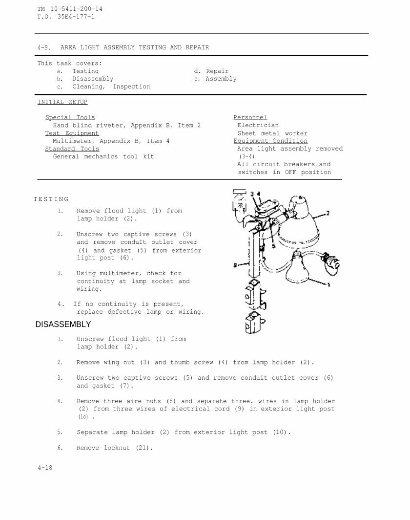
TM 10-5411-200-14T.O. 35E4-177-1
4-9. AREA LIGHT ASSEMBLY TESTING AND REPAIR
This task covers:a. Testing d. Repairb. Disassembly e. Assemblyc. Cleaning, Inspection
INITIAL SETUP
Special ToolsHand blind riveter, Appendix B, Item 2
PersonnelElectrician
Test Equipment Sheet metal workerMultimeter, Appendix B, Item 4 Equipment Condition
Standard Tools Area light assembly removedGeneral mechanics tool kit (3-4)
All circuit breakers andswitches in OFF position
TESTING
1. Remove flood light (1) fromlamp holder (2).
2. Unscrew two captive screws (3)and remove conduIt outlet cover(4) and gasket (5) from exteriorlight post (6).
3. Using multimeter, check forcontinuity at lamp socket andwiring.
4. If no continuity is present,replace defective lamp or wiring.
DISASSEMBLY
1.
2.
3.
4.
5.
6.
4-18
Unscrew flood light (1) fromlamp holder (2).
Remove wing nut (3) and thumb screw (4) from lamp holder (2).
Unscrew two captive screws (5) and remove conduit outlet cover (6)and gasket (7).
Remove three wire nuts (8) and separate three. wires in lamp holder(2) from three wires of electrical cord (9) in exterior light post(lo) .
Separate lamp holder (2) from exterior light post (10).
Remove locknut (21).
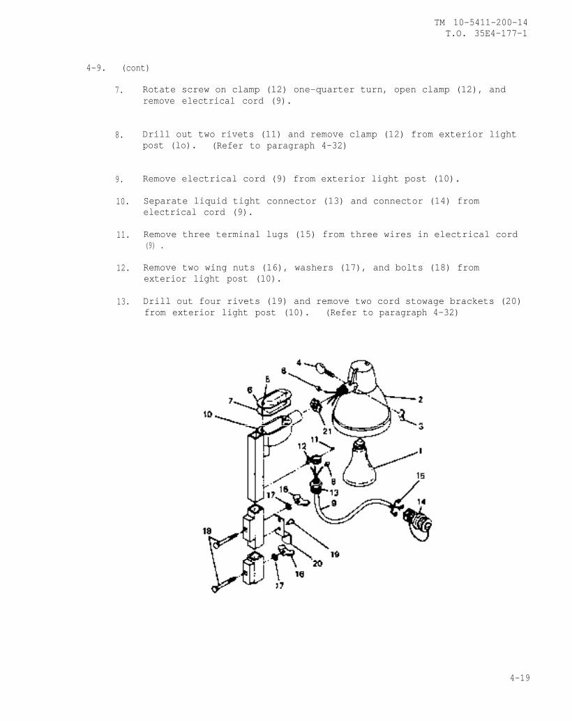
TM 10-5411-200-14T.O. 35E4-177-1
4-9. (cont)
7.
8.
9.
10.
11.
12.
13.
Rotate screw on clamp (12) one-quarter turn, open clamp (12), andremove electrical cord (9).
Drill out two rivets (11) and remove clamp (12) from exterior lightpost (lo). (Refer to paragraph 4-32)
Remove electrical cord (9) from exterior light post (10).
Separate liquid tight connector (13) and connector (14) fromelectrical cord (9).
Remove three terminal lugs (15) from three wires in electrical cord(9) .
Remove two wing nuts (16), washers (17), and bolts (18) fromexterior light post (10).
Drill out four rivets (19) and remove two cord stowage brackets (20)from exterior light post (10). (Refer to paragraph 4-32)
4-19
TM 10-5411-200-14T.O. 35E4-177-1
4-9. (cont)
CLEANING, INSPECTION
1. Clean area light assembly and component surfaces.
2. Inspect mounting surfaces for corrosion and damage.
3. Inspect for and replace if necessary:
a. Missing or damaged component
b. Corrosion or paint damage.
R E P A I R
Repair corrosion or paint damage. (Refer to paragraph 4-43)
ASSEMBLY
1.
2.
3.
4.
5.
6.
7.
8.
Position two cord stowage brackets (20) on exterior light post (10)and install four rivets (19). (Refer to paragraph 4-32)
Install two bolts (18), washers (17), and wing nuts (16) in exteriorlight post (10).
Assemble three terminal lugs (15) to three wires on one end ofelectrical cord (9) and attach connector (14) at that end.
Place electrical cord (9) through clamp (12) and attach clamp toexterior light post with two rivets (11) and close clamp. (Refer to4-32.)
Assemble liquid tight connector (13) to opposite end of electricalcord (9) and install assembly in exterior light post (10). Makesure three wires extend through opening at top of exterior lightpost (lo).
Assemble locknut (21) on lamp holder (2).
Assemble lamp holder (2) to exterior light post (10) and installthumb screw (4) and wing nut (3). Make sure three wires extendthrough opening at top of exterior light post (10).
Connect three wires from electrical. cord (9) to three wires fromlamp holder (2) as follows:
From ToElectrical Cord Lamp Holder
Black Wire Black WireWhite Wire White WireGreen Wire Bare Wire
4-20
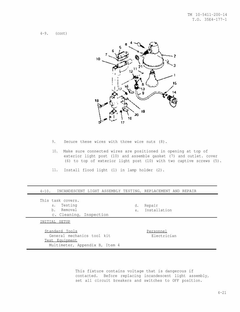
TM 10-5411-200-14T.O. 35E4-177-1
4-9. (cont)
9. Secure these wires with three wire nuts (8).
10. Make sure connected wires are positioned in opening at top ofexterior light post (10) and assemble gasket (7) and outlet. cover(6) to top of exterior light post (10) with two captive screws (5).
11. Install flood light (1) in lamp holder (2).
4-10. INCANDESCENT LIGHT ASSEMBLY TESTING, REPLACEMENT AND REPAIR
This task covers.a. Testing d. Repairb. Removal e. Installationc. Cleaning, Inspection
INITIAL SETUP
Standard Tools PersonnelGeneral mechanics tool kit Electrician
Test EquipmentMultimeter, Appendix B, Item 4
This fixture contains voltage that is dangerous ifcontacted. Before replacing incandescent light assembly,set all circuit breakers and switches to OFF position.
4-21

TM 10-5411-200-14T.O. 35E4-177-1
4-10. (cont)
TESTING
1.
2.
3.
4.
5.
6.
Set all circuit breakers and switches to OFF position.
Remove two screws (1) and cover (2).
Unscrew bulb (3) from light fixture (4).
Remove screw (5) and separate light fixture (4) from light fixtureadapter (6) as far as it will go.
Using multimeter, check for continuity at bulb socket and wiring.
If no continuity is present, replace defective light fixture orwiring.
1. Remove two screws (1) and switch cover (2).
2. Remove two screws (3) and pull switch (4) from outlet box (27) asfar as it will go.
4-22
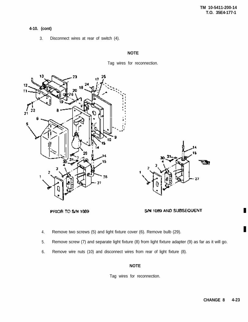
TM 10-5411-200-14T.O. 35E4-177-1
4-10. (cont)
3. Disconnect wires at rear of switch (4).
NOTE
Tag wires for reconnection.
4. Remove two screws (5) and light fixture cover (6). Remove bulb (29).
5. Remove screw (7) and separate light fixture (8) from light fixture adapter (9) as far as it will go.
6. Remove wire nuts (10) and disconnect wires from rear of light fixture (8).
NOTE
Tag wires for reconnection.
CHANGE 8 4-23
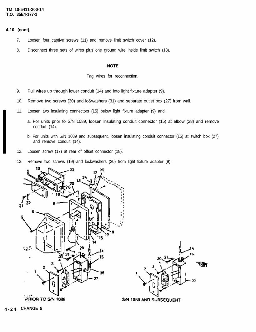
TM 10-5411-200-14T.O. 35E4-177-1
4-10. (cont)
7. Loosen four captive screws (11) and remove limit switch cover (12).
8. Disconnect three sets of wires plus one ground wire inside limit switch (13).
NOTE
Tag wires for reconnection.
9. Pull wires up through lower conduit (14) and into light fixture adapter (9).
10. Remove two screws (30) and lo&washers (31) and separate outlet box (27) from wall.
11. Loosen two insulating connectors (15) below light fixture adapter (9) and:
a. For units prior to S/N 1089, loosen insulating conduit connector (15) at elbow (28) and removeconduit (14).
b. For units with S/N 1089 and subsequent, loosen insulating conduit connector (15) at switch box (27)and remove conduit (14).
12. Loosen screw (17) at rear of offset connector (18).
13. Remove two screws (19) and lockwashers (20) from light fixture adapter (9).
4 - 2 4 CHANGE 8
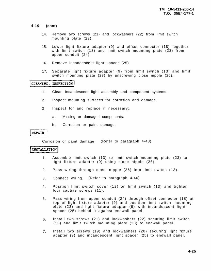
TM 10-5411-200-14T.O. 35E4-177-1
4-10. (cont)
14. Remove two screws (21) and lockwashers (22) from limit switchmounting plate (23).
15. Lower l ight f ixture adapter (9) and offset connector (18) togetherwith l imit switch (13) and l imit switch mounting plate (23) fromupper conduit (24).
16. Remove incandescent light spacer (25).
17. Separate l ight f ix ture adapter (9) f rom l imi t swi tch (13) and l imi tswitch mounting plate (23) by unscrewing close nipple (26).
1. Clean incandescent light assembly and component systems.
2. Inspect mounting surfaces for corrosion and damage.
3 . Inspect for and replace i f necessary:.
a. Missing or damaged components.
b . Corrosion or paint damage.
Corrosion or paint damage. (Refer to paragraph 4-43)
6.
1.
2.
3.
4.
5.
7.
Assemble l imit switch (13) to l imit switch mounting plate (23) tol ight f ix ture adapter (9) us ing c lose n ipp le (26) .
Pass wi r ing through c lose n ipp le (26) in to l imi t swi tch (13) .
Connect wiring. (Refer to paragraph 4-46)
Pos i t ion l imi t swi tch cover (12) on l imi t swi tch (13) and t ightenfour captive screws (11).
Pass wir ing from upper conduit (24) through offset connector (18) attop o f l igh t f ix ture adapter (9) and pos i t ion l imi t swi tch mount ingp la te (23) and l ight f ix ture adapter (9) w i th incandescent l ightspacer (25) behind i t against endwall panel.
Instal l two screws (21) and lockwashers (22) securing l imit switch(13) and l imit switch mounting plate (23) to endwall panel.
Instal l two screws (19) and lockwashers (20) securing l ight f ixtureadapter (9) and incandescent l ight spacer (25) to endwall panel.
4-25
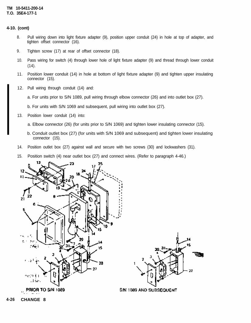
TM 10-5411-200-14T.O. 35E4-177-1
4-10. (cont)
8. Pull wiring down into light fixture adapter (9), position upper conduit (24) in hole at top of adapter, andtighten offset connector (16).
9. Tighten screw (17) at rear of offset connector (18).
10. Pass wiring for switch (4) through lower hole of light fixture adapter (9) and thread through lower conduit(14).
11. Position lower conduit (14) in hole at bottom of light fixture adapter (9) and tighten upper insulatingconnector (15).
12. Pull wiring through conduit (14) and:
a. For units prior to S/N 1089, pull wiring through elbow connector (26) and into outlet box (27).
b. For units with S/N 1069 and subsequent, pull wiring into outlet box (27).
13. Position lower conduit (14) into:
a. Elbow connector (26) (for units prior to S/N 1069) and tighten lower insulating connector (15).
b. Conduit outlet box (27) (for units with S/N 1069 and subsequent) and tighten lower insulatingconnector (15).
14. Position outlet box (27) against wall and secure with two screws (30) and lockwashers (31).
15. Position switch (4) near outlet box (27) and connect wires. (Refer to paragraph 4-46.)
4-26 CHANGE 8
TM 10-5411-200-14T.O. 35E4-177-1
4-10. (cont)
16. Position switch (4) in outlet box (27) and secure with two screws (3).
17. Position switch cover (2) on switch (4) and secure with two screws (l).
18. Position light fixture (8) near light fixture adapter (9) and connectwires. (Refer to paragraph 4-46)
19. Position light fixture (8) on light fixture adapter (9) and secure withone screw (7). Install bulb (29).
20. Position light fixture cover (6) on light fixture (8) and secure withtwo screws (5).
4-11. HINGED ROOF AREA CEILING LIGHT TESTING AND REPAIR
This task covers:a. Testing d. Repairb. Disassembly e. Assemblyc. Cleaning, Inspection
INITIAL SETUP
Special TOOls PersonnelHand blind riveter, Appendix B, Item 2 Electrician
Test Equipment Equipment ConditionMultimeter, Appendix B, Item 4 Hinged roof area ceiling
Standard Tools light removed (paragraphGeneral mechanics tool kit 3-5) All circuit breakers
and switches in OFF position
TESTING
WARNING
In the event of lamp breakage, care must be takenin the removal of broken glass fragments and whitephosphorus dust that may be dispersed within thefixture. Inhalation of phosphorus dust could causedangerous injury. Set all circuit breakers andswitches to OFF position.
4-27
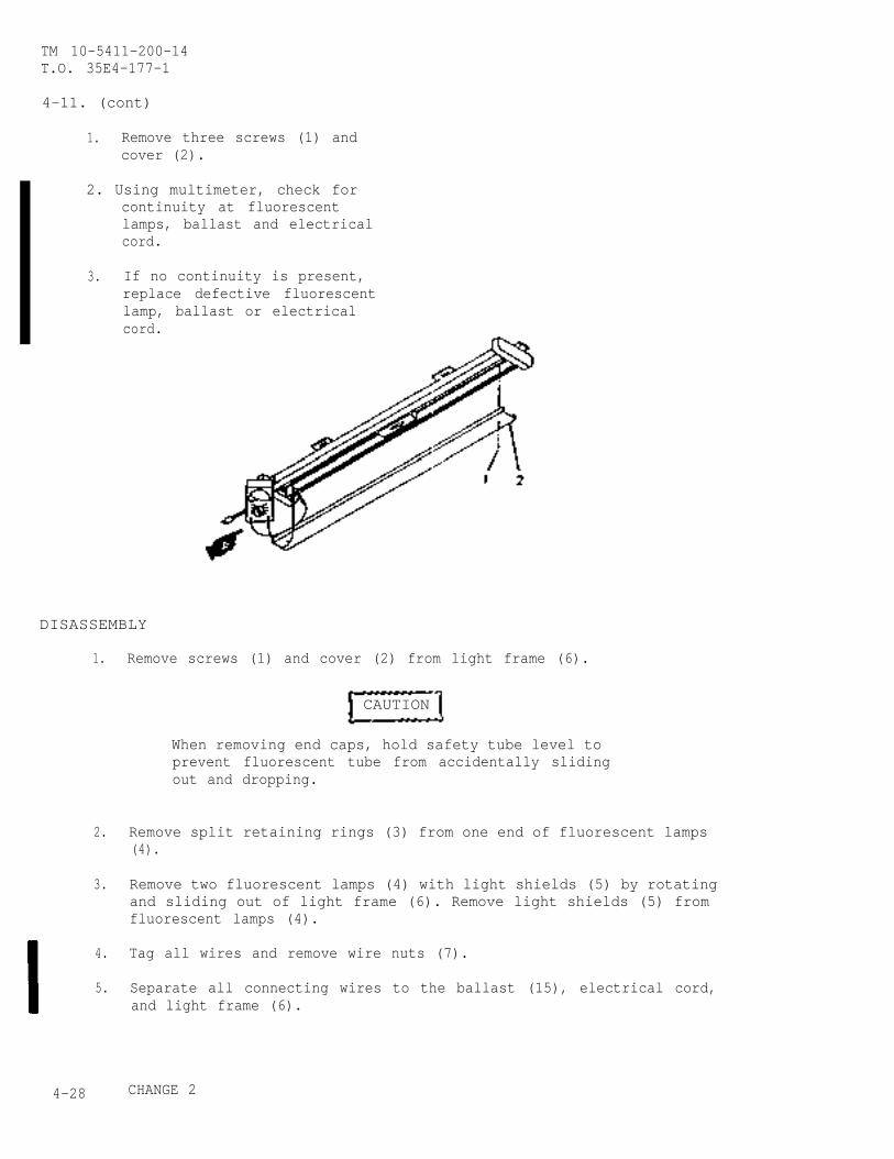
TM 10-5411-200-14T.O. 35E4-177-1
4-11. (cont)
1. Remove three screws (1) andcover (2).
2. Using multimeter, check forcontinuity at fluorescentlamps, ballast and electricalcord.
3. If no continuity is present,replace defective fluorescentlamp, ballast or electricalcord.
DISASSEMBLY
1.
2.
3.
4.
5.
4-28
Remove screws (1) and cover (2) from light frame (6).
CAUTION
When removing end caps, hold safety tube level toprevent fluorescent tube from accidentally slidingout and dropping.
Remove split retaining rings (3) from one end of fluorescent lamps(4).
Remove two fluorescent lamps (4) with light shields (5) by rotatingand sliding out of light frame (6). Remove light shields (5) fromfluorescent lamps (4).
Tag all wires and remove wire nuts (7).
Separate all connecting wires to the ballast (15), electrical cord,and light frame (6).
CHANGE 2
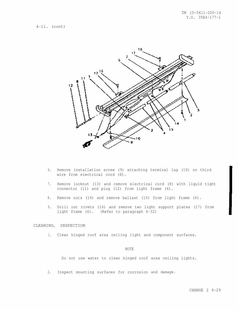
4-11. (cont)
TM 10-5411-200-14T.O. 35E4-177-1
6.
7.
8.
9.
Remove installation screw (9) attaching terminal lug (10) on thirdwire from electrical cord (8).
Remove locknut (13) and remove electrical cord (8) with liquid tightconnector (11) and plug (12) from light frame (6).
Remove nuts (14) and remove ballast (15) from light frame (6).
Drill out rivets (16) and remove two light support plates (17) fromlight frame (6). (Refer to paragraph 4-32)
CLEANING, INSPECTION
1. Clean hinged roof area ceiling light and component surfaces.
NOTE
Do not use water to clean hinged roof
2. Inspect mounting surfaces for corrosion
area ceiling lights.
and damage.
CHANGE 2 4-29
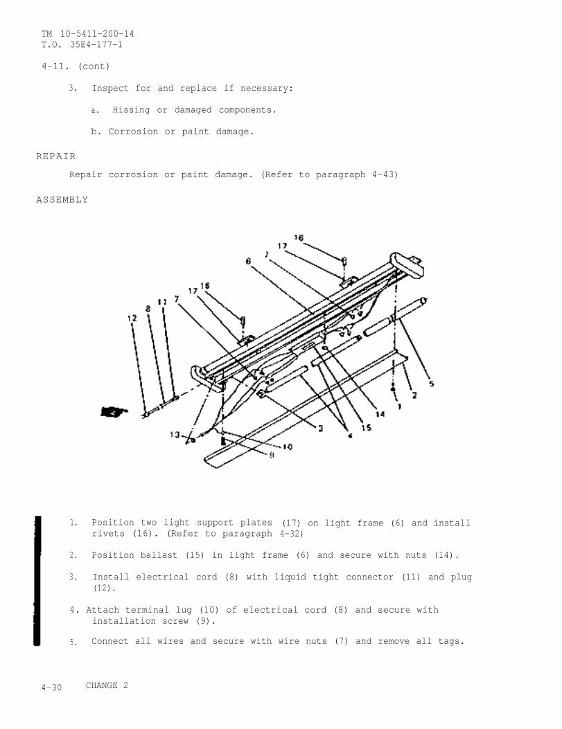
TM 10-5411-200-14T.O. 35E4-177-1
4-11. (cont)
3. Inspect for and replace if necessary:
a. Hissing or damaged components.
b. Corrosion or paint damage.
REPAIR
Repair corrosion or paint damage. (Refer to paragraph 4-43)
ASSEMBLY
1. Position two light support platesrivets (16). (Refer to paragraph
(17) on light frame (6) and install4-32)
2. Position ballast (15) in light frame (6) and secure with nuts (14).
3. Install electrical cord (8) with liquid tight connector (11) and plug(12).
4. Attach terminal lug (10) of electrical cord (8) and secure withinstallation screw (9).
5. Connect all wires and secure with wire nuts (7) and remove all tags.
4-30 CHANGE 2
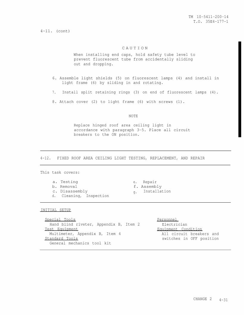
4-11. (cont)
TM 10-5411-200-14T.O. 35E4-177-1
C A U T I O N
When installing end caps, hold safety tube level toprevent fluorescent tube from accidentally slidingout and dropping.
6. Assemble light shields (5) on fluorescent lamps (4) and install inlight frame (6) by sliding in and rotating.
7. Install split retaining rings (3) on end of fluorescent lamps (4).
8. Attach cover (2) to light frame (6) with screws (l).
NOTE
Replace hinged roof area ceiling light inaccordance with paragraph 3-5. Place all circuitbreakers to the ON position.
4-12. FIXED ROOF AREA CEILING LIGHT TESTING, REPLACEMENT, AND REPAIR
This task covers:
a. Testing e. Repairb. Removal f. Assemblyc. Disassembly g. Installationd. Cleaning, Inspection
INITIAL SETUP
Special Tools PersonnelHand blind riveter, Appendix B, Item 2 Electrician
Test Equipment Equipment ConditionMultimeter, Appendix B, Item 4 All circuit breakers and
Standard Tools switches in OFF positionGeneral mechanics tool kit
CHANGE 2 4-31
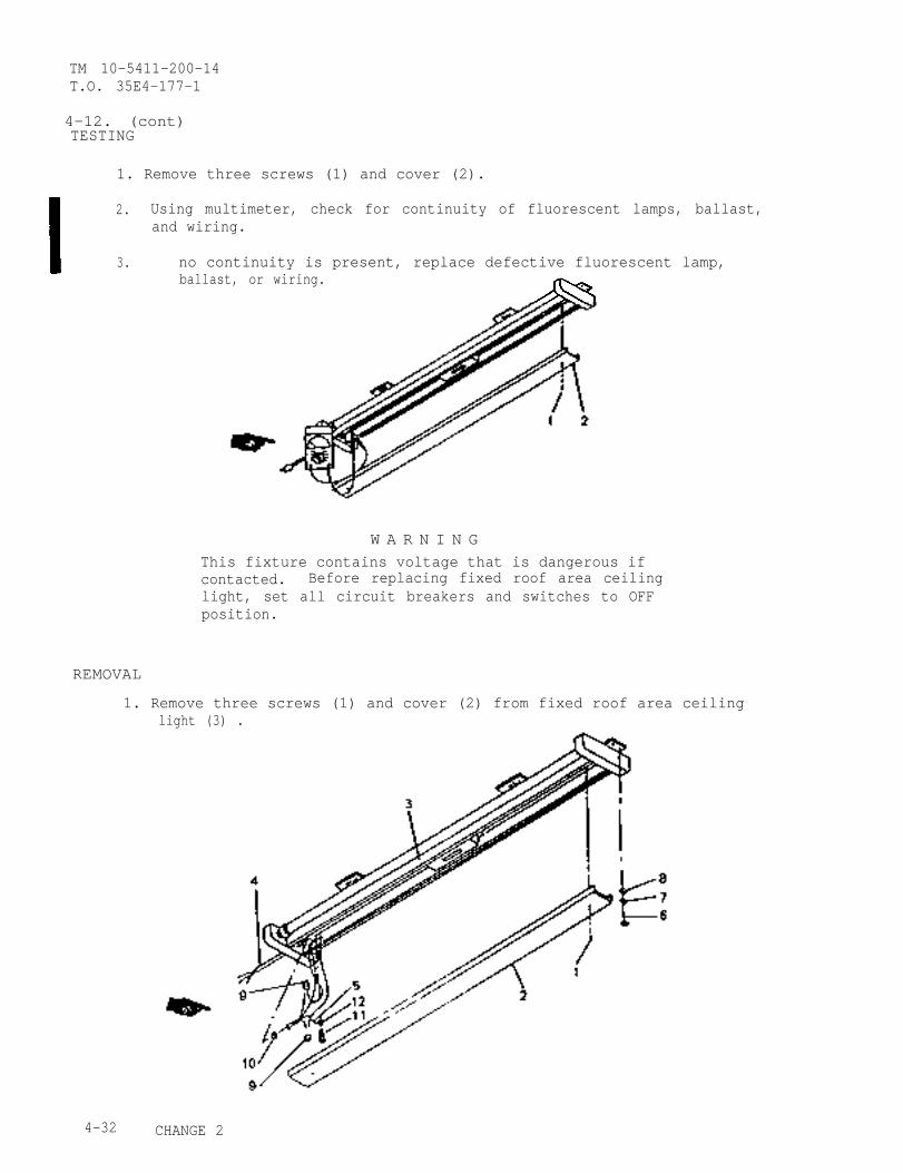
TM 10-5411-200-14T.O. 35E4-177-1
4-12. (cont)TESTING
1. Remove three screws (1) and cover (2).
2.
3.
Using multimeter, check for continuity of fluorescent lamps, ballast,and wiring.
no continuity is present, replace defective fluorescent lamp,ballast, or wiring.
W A R N I N GThis fixture contains voltage that is dangerous ifcontacted. Before replacing fixed roof area ceilinglight, set all circuit breakers and switches to OFFposition.
REMOVAL
1. Remove three screws (1) and cover (2) from fixed roof area ceilinglight (3) .
4-32 CHANGE 2
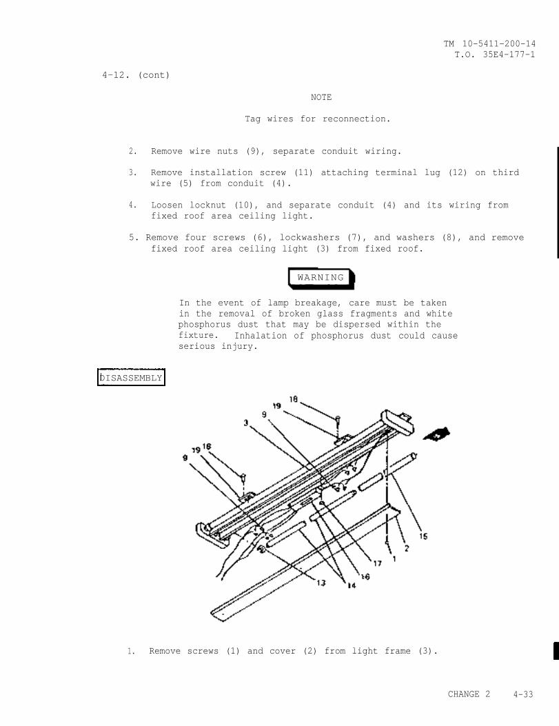
TM 10-5411-200-14T.O. 35E4-177-1
4-12. (cont)
NOTE
Tag wires for reconnection.
2. Remove wire nuts (9), separate conduit wiring.
3. Remove installation screw (11) attaching terminal lug (12) on thirdwire (5) from conduit (4).
4. Loosen locknut (10), and separate conduit (4) and its wiring fromfixed roof area ceiling light.
5. Remove four screws (6), lockwashers (7), and washers (8), and removefixed roof area ceiling light (3) from fixed roof.
WARNING
In the event of lamp breakage, care must be takenin the removal of broken glass fragments and whitephosphorus dust that may be dispersed within thefixture. Inhalation of phosphorus dust could causeserious injury.
DISASSEMBLY
1. Remove screws (1) and cover (2) from light frame (3).
CHANGE 2 4-33
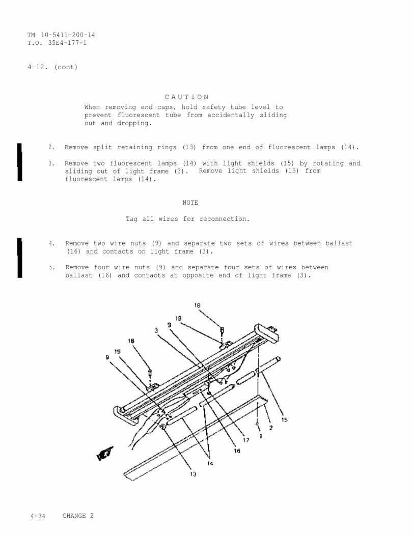
TM 10-5411-200-14T.O. 35E4-177-1
4-12. (cont)
2.
3.
4.
5.
C A U T I O NWhen removing end caps, hold safety tube level toprevent fluorescent tube from accidentally slidingout and dropping.
Remove split retaining rings (13) from one end of fluorescent lamps (14).
Remove two fluorescent lamps (14) with light shields (15) by rotating andsliding out of light frame (3). Remove light shields (15) fromfluorescent lamps (14).
NOTE
Tag all wires for reconnection.
Remove two wire nuts (9) and separate two sets of wires between ballast(16) and contacts on light frame (3).
Remove four wire nuts (9) and separate four sets of wires betweenballast (16) and contacts at opposite end of light frame (3).
4-34 CHANGE 2
TM 10-5411-200-14T.O. 35E4-177-1
4-12. (cont)
6. Remove nuts (17) and remove ballast (16) from light frame (3).
7. Drill out rivets (18) and remove two light support plates (19) fromlight frame (3). (Refer to paragraph 4-32)
CLEANING, INSPECTION
1. Clean hinged roof area ceiling light and component surfaces.
2. Inspect mounting surfaces for corrosion and damage.
3. Inspect for and replace if necessary:
a. Missing or damaged components.
b. Corrosion or paint damage.
REPAIR
Repair corrosion or paint damage. (Refer to paragraph 4-43)
ASSEMBLY
1. Position two light support plates (19) on light frame (3) andinstall rivets (18). (Refer to paragraph 4-32)
2. Position ballast (16) in light frame (3) and secure with nuts (17).
3. Connect two wires from ballast (16) to contacts on light frame (3)as follows:
Yellow to YellowYellow to Black
4. Connect four wireslight frame (3) as
Red to BlackRed to BlackBlue to WhiteBlue to White
from ballast (16) to contacts at opposite end offollows:
CHANGE 2 4-35
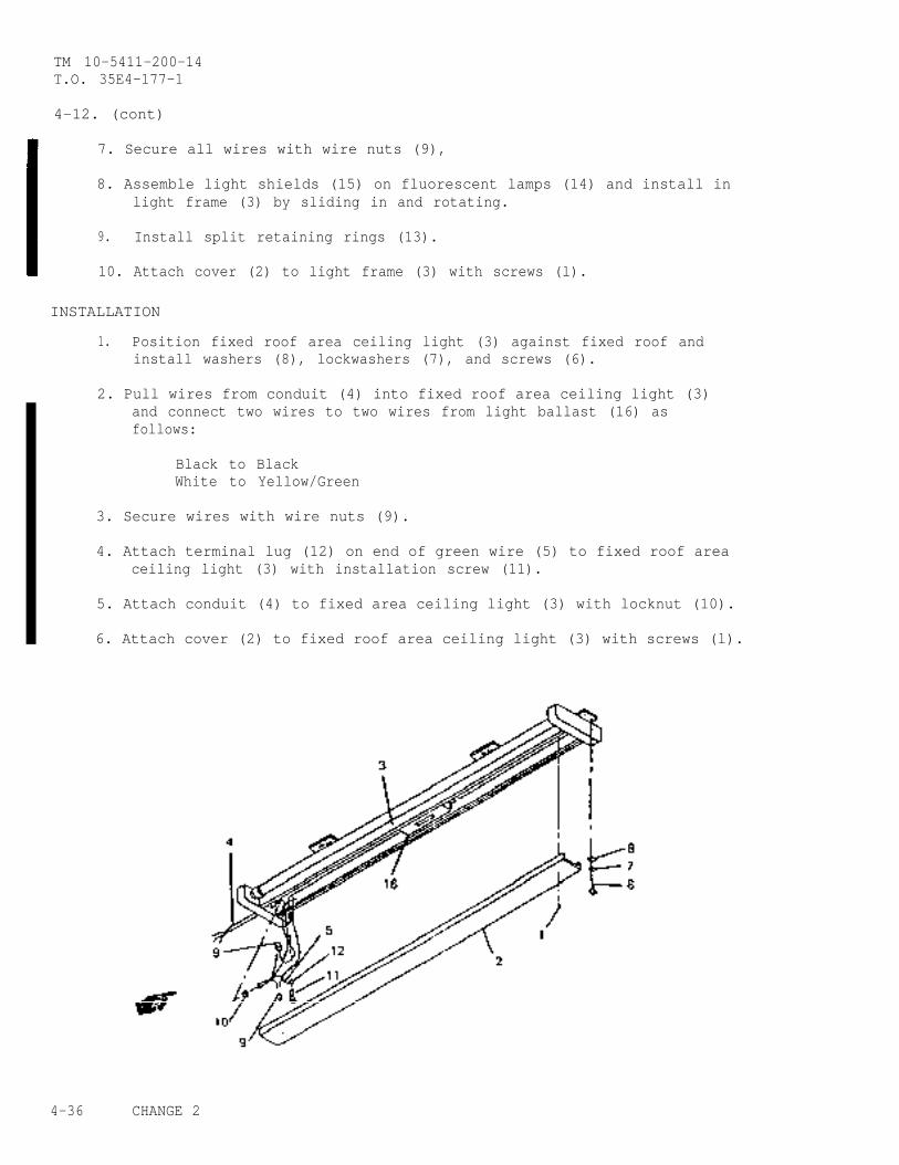
TM 10-5411-200-14T.O. 35E4-177-1
4-12. (cont)
7. Secure all wires with wire nuts (9),
8. Assemble light shields (15) on fluorescent lamps (14) and install inlight frame (3) by sliding in and rotating.
9. Install split retaining rings (13).
10. Attach cover (2) to light frame (3) with screws (l).
INSTALLATION
1. Position fixed roof area ceiling light (3) against fixed roof andinstall washers (8), lockwashers (7), and screws (6).
2. Pull wires from conduit (4) into fixed roof area ceiling light (3)and connect two wires to two wires from light ballast (16) asfollows:
Black to BlackWhite to Yellow/Green
3. Secure wires with wire nuts (9).
4. Attach terminal lug (12) on end of green wire (5) to fixed roof areaceiling light (3) with installation screw (11).
5. Attach conduit (4) to fixed area ceiling light (3) with locknut (10).
6. Attach cover (2) to fixed roof area ceiling light (3) with screws (l).
4-36 CHANGE 2
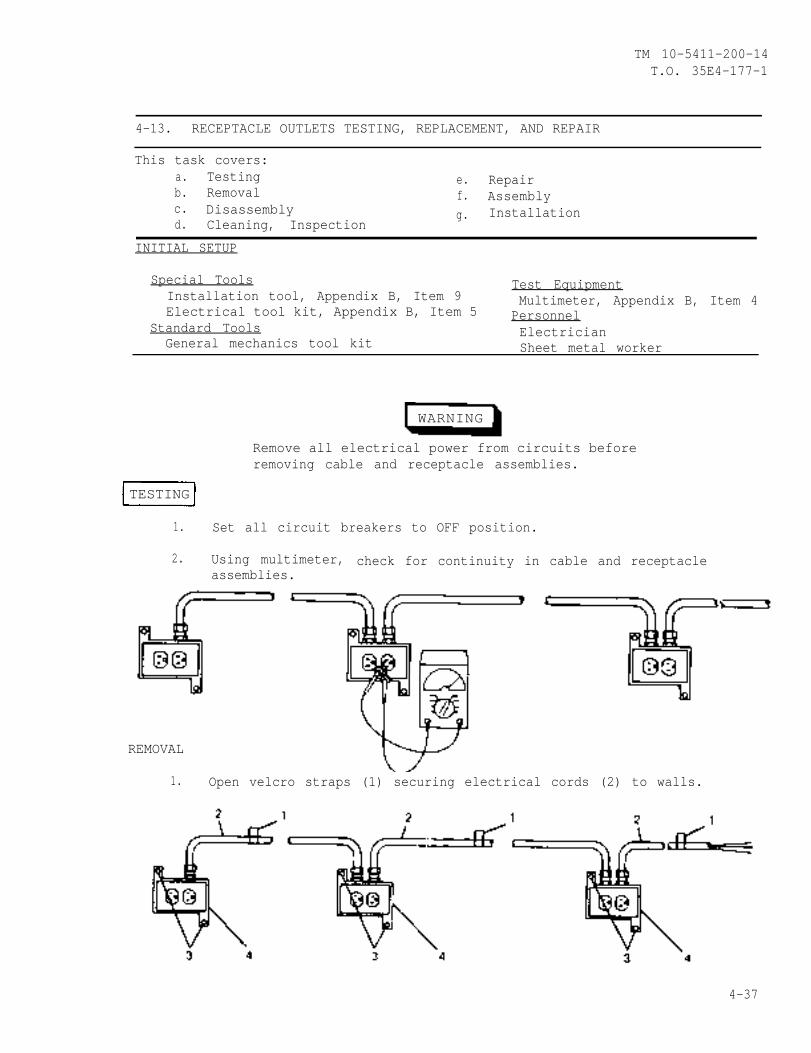
TM 10-5411-200-14T.O. 35E4-177-1
4-13. RECEPTACLE OUTLETS TESTING, REPLACEMENT, AND REPAIR
This task covers:a. Testing e. Repairb. Removal f. Assemblyc. Disassembly Installationd.
g.Cleaning, Inspection
INITIAL SETUP
Special Tools Test EquipmentInstallation tool, Appendix B, Item 9 Multimeter, Appendix B, Item 4Electrical tool kit, Appendix B, Item 5 Personnel
Standard Tools ElectricianGeneral mechanics tool kit Sheet metal worker
WARNING
Remove all electrical power from circuits beforeremoving cable and receptacle assemblies.
TESTING
1. Set all circuit breakers to OFF position.
2. Using multimeter, check for continuity in cable and receptacleassemblies.
REMOVAL
1. Open velcro straps (1) securing electrical cords (2) to walls.
4-37
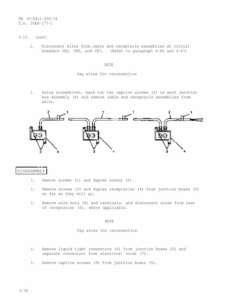
TM 10-5411-200-14T.O. 35E4-177-1
4-13. (cont)
2. Disconnect wires from cable and receptacle assemblies at circuitbreakers CB3, CB5, and CB7. (Refer to paragraph 4-46 and 4-47)
NOTE
Tag wires for reconnection
3. Using screwdriver, back out two captive screws (3) on each junctionbox assembly (4) and remove cable and receptacle assemblies fromwalls.
DISASSEMBLY
1. Remove screws (1) and duplex covers (2).
2. Remove screws (3) and duplex receptacles (4) from junction boxes (5)as far as they will go.
3. Remove wire nuts (8) and terminals, and disconnect wires from rearof receptacles (4), where applicable.
NOTE
Tag wires for reconnection
4. Remove liquid tight connectors (6) from junction boxes (5) andseparate connectors from electrical cords (7).
5. Remove captive screws (9) from junction boxes (5).
4-38
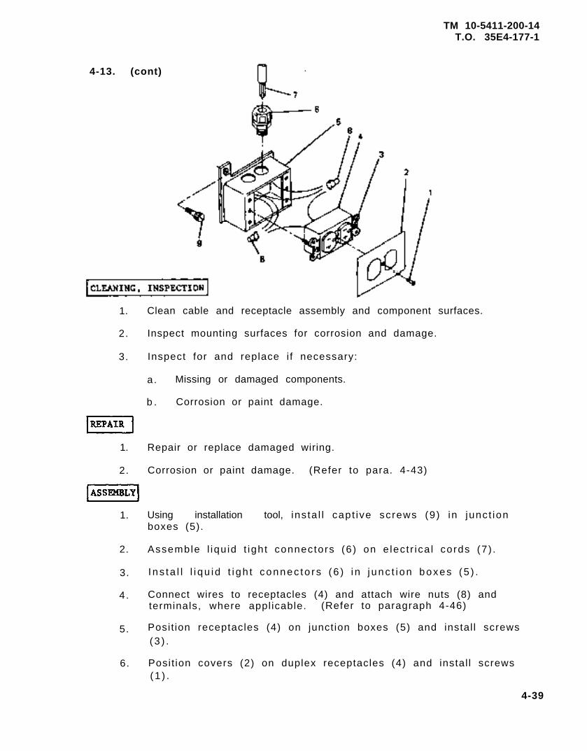
TM 10-5411-200-14T.O. 35E4-177-1
4-13. (cont)
1. Clean cable and receptacle assembly and component surfaces.
2. Inspect mounting surfaces for corrosion and damage.
3. Inspect for and replace i f necessary:
a . Missing or damaged components.
b . Corrosion or paint damage.
1. Repair or replace damaged wiring.
2. Corrosion or paint damage. (Refer to para. 4-43)
1. Using installation tool, ins ta l l capt ive screws (9) in junct ionboxes (5).
2. Assemble l iqu id t ight connectors (6) on e lec t r ica l cords (7) .
3. I ns ta l l l i qu id t i gh t connec to rs (6 ) i n j unc t i on boxes (5 ) .
4 . Connect wires to receptacles (4) and attach wire nuts (8) andterminals, where appl icable. (Refer to paragraph 4-46)
5. Posit ion receptacles (4) on junct ion boxes (5) and instal l screws(3 ) .
6. Posit ion covers (2) on duplex receptacles (4) and instal l screws(1 ) .
4-39
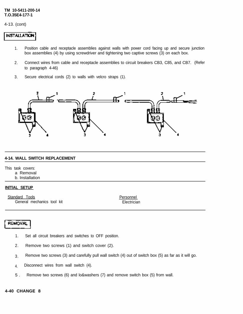
TM 10-5411-200-14T.O.35E4-177-1
4-13. (cont)
1. Position cable and receptacle assemblies against walls with power cord facing up and secure junctionbox assemblies (4) by using screwdriver and tightening two captive screws (3) on each box.
2. Connect wires from cable and receptacle assemblies to circuit breakers CB3, C85, and CB7. (Referto paragraph 4-46)
3. Secure electrical cords (2) to walls with velcro straps (1).
4-14. WALL SWlTCH REPLACEMENT
This task covers:a Removalb. Installation
INlTlAL SETUP
Standard Tools PersonnelGeneral mechanics tool kit Electrician
1. Set all circuit breakers and switches to OFF position.
2. Remove two screws (1) and switch cover (2).
3. Remove two screws (3) and carefully pull wall switch (4) out of switch box (5) as far as it will go.
4. Disconnect wires from wall switch (4).
5 . Remove two screws (6) and lo&washers (7) and remove switch box (5) from wall.
4-40 CHANGE 8

TM 10-5411-200-14T.O. 35E4-177-1
4-14. (cont)
1.
2.
3.
4.
Position switch box (5) on wall and secure with two lo&washers (7) and screws (6).
Position wall switch (4) near switch box (5) and connect wires to rear of switch. (Refer to paragraph4-46.)
Position wall switch (4) in switch box (5) and secure with two screws (3).
Position switch cover (2) against switch box (5) and secure with two screws (1).
4-15. BLACKOUT SWITCH REPLACEMENT, REPAIR, AND ADJUSTMENT
This task covers:a. Removalb. Cleaning, Inspectionc. Repair
d. Installatione. Adjustment
INITIAL SETUP
Standard Tools PersonnelGeneral mechanics tool kit Electrician
CHANGE 8 4-41
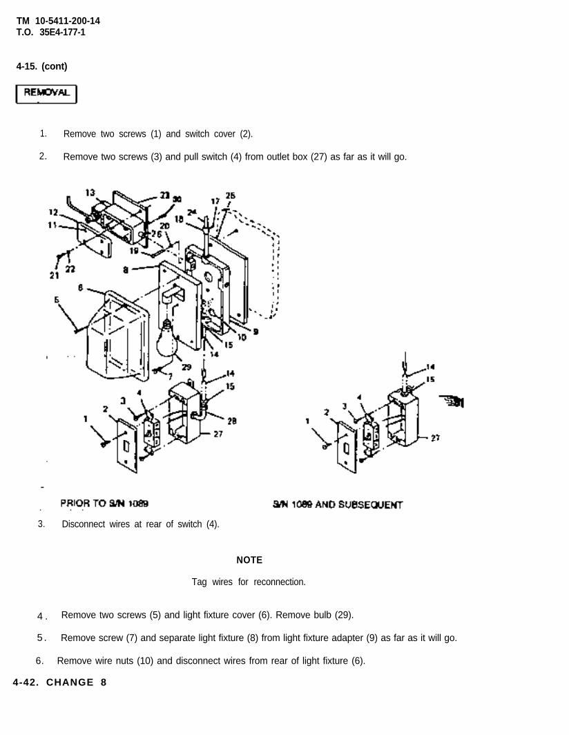
TM 10-5411-200-14T.O. 35E4-177-1
4-15. (cont)
1. Remove two screws (1) and switch cover (2).
2. Remove two screws (3) and pull switch (4) from outlet box (27) as far as it will go.
3. Disconnect wires at rear of switch (4).
NOTE
Tag wires for reconnection.
4 . Remove two screws (5) and light fixture cover (6). Remove bulb (29).
5 . Remove screw (7) and separate light fixture (8) from light fixture adapter (9) as far as it will go.
6. Remove wire nuts (10) and disconnect wires from rear of light fixture (6).
4-42. CHANGE 8
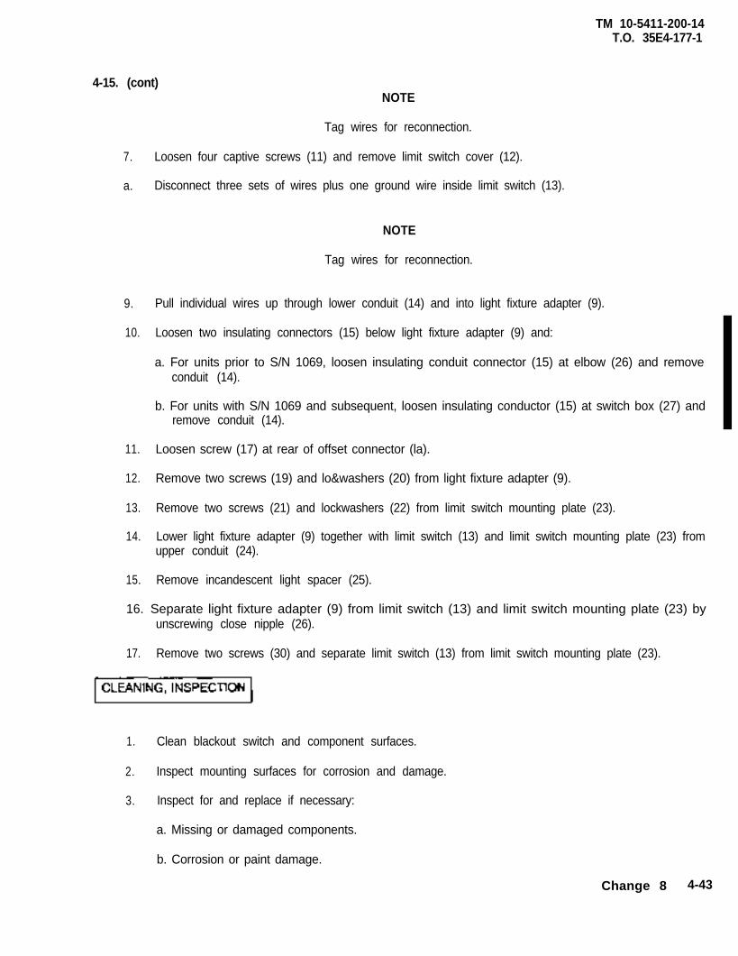
TM 10-5411-200-14T.O. 35E4-177-1
4-15. (cont)NOTE
Tag wires for reconnection.
7. Loosen four captive screws (11) and remove limit switch cover (12).
a. Disconnect three sets of wires plus one ground wire inside limit switch (13).
NOTE
Tag wires for reconnection.
9. Pull individual wires up through lower conduit (14) and into light fixture adapter (9).
10. Loosen two insulating connectors (15) below light fixture adapter (9) and:
a. For units prior to S/N 1069, loosen insulating conduit connector (15) at elbow (26) and removeconduit (14).
b. For units with S/N 1069 and subsequent, loosen insulating conductor (15) at switch box (27) andremove conduit (14).
11. Loosen screw (17) at rear of offset connector (la).
12. Remove two screws (19) and lo&washers (20) from light fixture adapter (9).
13. Remove two screws (21) and lockwashers (22) from limit switch mounting plate (23).
14. Lower light fixture adapter (9) together with limit switch (13) and limit switch mounting plate (23) fromupper conduit (24).
15. Remove incandescent light spacer (25).
16. Separate light fixture adapter (9) from limit switch (13) and limit switch mounting plate (23) byunscrewing close nipple (26).
17. Remove two screws (30) and separate limit switch (13) from limit switch mounting plate (23).
1. Clean blackout switch and component surfaces.
2. Inspect mounting surfaces for corrosion and damage.
3. Inspect for and replace if necessary:
a. Missing or damaged components.
b. Corrosion or paint damage.
Change 8 4-43
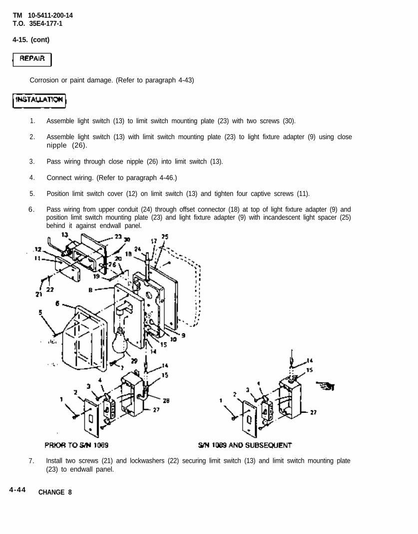
TM 10-5411-200-14T.O. 35E4-177-1
4-15. (cont)
Corrosion or paint damage. (Refer to paragraph 4-43)
1.
2.
3.
4.
5.
6.
Assemble light switch (13) to limit switch mounting plate (23) with two screws (30).
Assemble light switch (13) with limit switch mounting plate (23) to light fixture adapter (9) using closenipple (26).
Pass wiring through close nipple (26) into limit switch (13).
Connect wiring. (Refer to paragraph 4-46.)
Position limit switch cover (12) on limit switch (13) and tighten four captive screws (11).
Pass wiring from upper conduit (24) through offset connector (18) at top of light fixture adapter (9) andposition limit switch mounting plate (23) and light fixture adapter (9) with incandescent light spacer (25)behind it against endwall panel.
7. Install two screws (21) and lockwashers (22) securing limit switch (13) and limit switch mounting plate(23) to endwall panel.
4-44 CHANGE 8
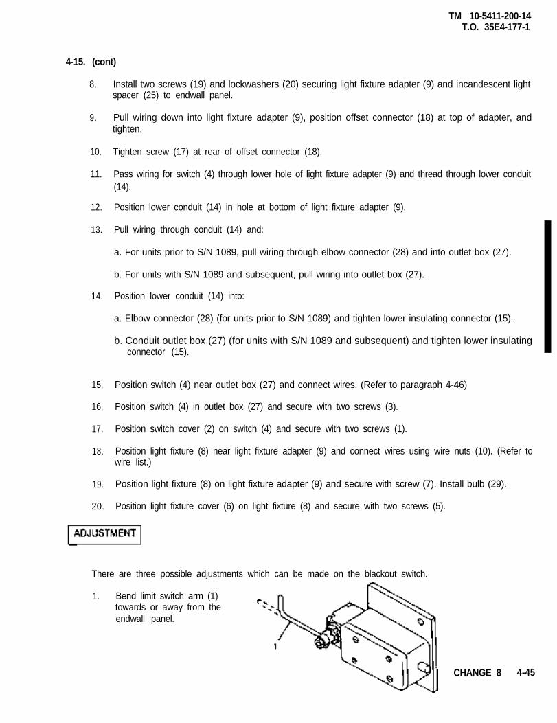
TM 10-5411-200-14T.O. 35E4-177-1
4-15. (cont)
8. Install two screws (19) and lockwashers (20) securing light fixture adapter (9) and incandescent lightspacer (25) to endwall panel.
9. Pull wiring down into light fixture adapter (9), position offset connector (18) at top of adapter, andtighten.
10.
11.
Tighten screw (17) at rear of offset connector (18).
Pass wiring for switch (4) through lower hole of light fixture adapter (9) and thread through lower conduit(14).
12.
13.
Position lower conduit (14) in hole at bottom of light fixture adapter (9).
Pull wiring through conduit (14) and:
a. For units prior to S/N 1089, pull wiring through elbow connector (28) and into outlet box (27).
b. For units with S/N 1089 and subsequent, pull wiring into outlet box (27).
14. Position lower conduit (14) into:
a. Elbow connector (28) (for units prior to S/N 1089) and tighten lower insulating connector (15).
b. Conduit outlet box (27) (for units with S/N 1089 and subsequent) and tighten lower insulatingconnector (15).
15.
16.
17.
18.
Position switch (4) near outlet box (27) and connect wires. (Refer to paragraph 4-46)
Position switch (4) in outlet box (27) and secure with two screws (3).
Position switch cover (2) on switch (4) and secure with two screws (1).
Position light fixture (8) near light fixture adapter (9) and connect wires using wire nuts (10). (Refer towire list.)
19.
20.
Position light fixture (8) on light fixture adapter (9) and secure with screw (7). Install bulb (29).
Position light fixture cover (6) on light fixture (8) and secure with two screws (5).
There are three possible adjustments which can be made on the blackout switch.
1. Bend limit switch arm (1)towards or away from theendwall panel.
CHANGE 8 4-45
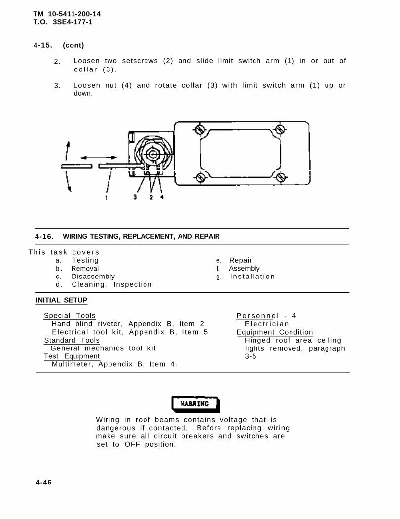
TM 10-5411-200-14T.O. 3SE4-177-1
4-15. (cont)
2. Loosen two setscrews (2) and slide limit switch arm (1) in or out ofc o l l a r ( 3 ) .
3. Loosen nut (4) and rotate col lar (3) with l imit switch arm (1) up ordown.
4-16. WIRING TESTING, REPLACEMENT, AND REPAIR
T h i s t a s k c o v e r s :a. Testingb . Removalc. Disassemblyd. Cleaning, Inspection
e. Repairf. Assemblyg. I ns ta l l a t i on
INITIAL SETUP
Special ToolsHand blind riveter, Appendix B, Item 2Elect r ica l too l k i t , Appendix B, I tem 5
Standard ToolsGeneral mechanics tool ki t
Test EquipmentMult imeter, Appendix B, I tem 4.
P e r s o n n e l - 4E l e c t r i c i a n
Equipment ConditionHinged roof area cei l inglights removed, paragraph3-5
Wiring in roof beams contains voltage that isdangerous i f contacted. Before replacing wir ing,make sure al l circuit breakers and switches areset to OFF position.
4-46
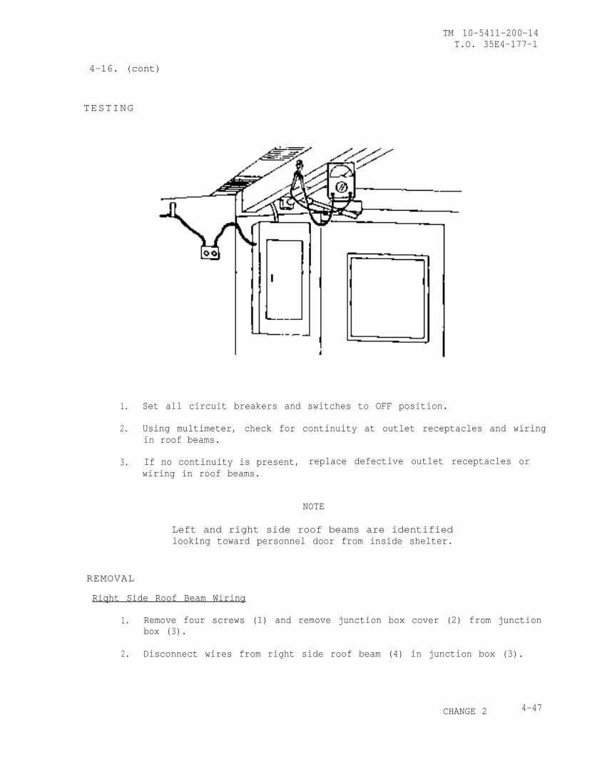
TM 10-5411-200-14T.O. 35E4-177-1
4-16. (cont)
TESTING
1. Set all circuit breakers and switches to OFF position.
2. Using multimeter, check for continuity at outlet receptacles and wiringin roof beams.
3. If no continuity is present, replace defective outlet receptacles orwiring in roof beams.
NOTE
Left and right side roof beams are identifiedlooking toward personnel door from inside shelter.
REMOVAL
Riqht Side Roof Beam Wiring
1. Remove four screws (1) and remove junction box cover (2) from junctionbox (3).
2. Disconnect wires from right side roof beam (4) in junction box (3).
CHANGE 2 4-47
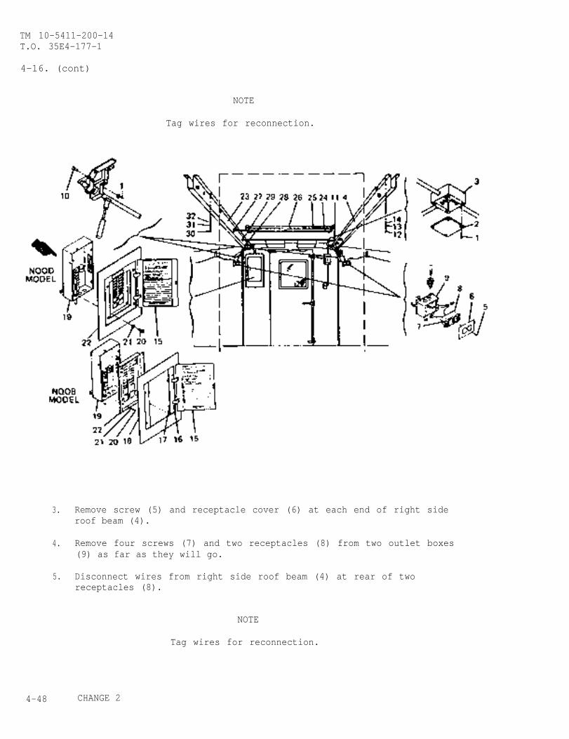
TM 10-5411-200-14T.O. 35E4-177-1
4-16. (cont)
NOTE
Tag wires for reconnection.
3. Remove screw (5) and receptacle cover (6) at each end of right sideroof beam (4).
4. Remove four screws (7) and two receptacles (8) from two outlet boxes(9) as far as they will go.
5. Disconnect wires from right side roof beam (4) at rear of tworeceptacles (8).
NOTE
Tag wires for reconnection.
4-48 CHANGE 2

TM 10-5411-200-14T.O. 35E4-177-1
4-16. (cont)
6. Remove three push bar assembly pins (10).
7. Loosen conduit locknuts (11) between junction box (3) and right sideroof beam (4).
8. Remove bolts (12), lockwashers (13), and washers (14) from right sideroof beam (4).
9. Remove right side roof beam (4) from roof panel.
Left Side Roof Beam Wiring
NOTE
This portion of the procedure is applicable to bothmodels of circuit breaker panels. Older models(NQOB) allow individually removing the panel coveror the panelboard. Newer model (NQOD) has thepanel cover and panelboard attached and is removedas a single unit.
10. Open circuit breaker panel doors (15).
11. On model NQOB, loosen four captive screws (16) and move four clampfingers (17) to the open position.
12. On model NQOB, lift panel cover (18) from the circuit breakerpanelboard (22).
13. On both models, remove four screws (20) and washers (21) and liftpanelboard (22) from circuit breaker box (19).
14. Disconnect wires from left side roof beam (23) in circuit breaker box(19) .
NOTE
Tag wires for reconnection.
CHANGE 2 4-49
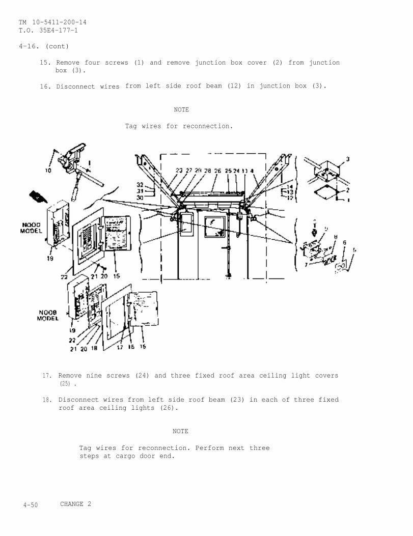
TM 10-5411-200-14T.O. 35E4-177-1
4-16. (cont)
15. Remove four screws (1) and remove junction box cover (2) from junctionbox (3).
16. Disconnect wires from left side roof beam (12) in junction box (3).
17.
18.
NOTE
Tag wires for reconnection.
Remove nine screws (24) and three fixed roof area ceiling light covers(25) .
Disconnect wires from left side roof beam (23) in each of three fixedroof area ceiling lights (26).
NOTE
Tag wires for reconnection. Perform next threesteps at cargo door end.
4-50 CHANGE 2
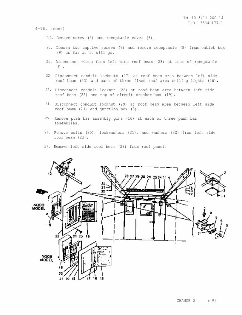
TM 10-5411-200-14T.O. 35E4-177-1
4-16. (cont)
19. Remove screw (5) and receptacle cover (6).
20.
21.
22.
23.
24.
25.
26.
27.
Loosen two captive screws (7) and remove receptacle (8) from outlet box(9) as far as it will go.
Disconnect wires from left side roof beam (23) at rear of receptacle(8) .
Disconnect conduit locknuts (27) at roof beam area between left sideroof beam (23) and each of three fixed roof area ceiling lights (26).
Disconnect conduit locknut (28) at roof beam area between left sideroof beam (23) and top of circuit breaker box (19).
Disconnect conduit locknut (29) at roof beam area between left sideroof beam (23) and junction box (3).
Remove push bar assembly pins (10) at each of three push barassemblies.
Remove bolts (30), lockwashers (31), and washers (32) from left sideroof beam (23).
Remove left side roof beam (23) from roof panel.
CHANGE 2 4-51
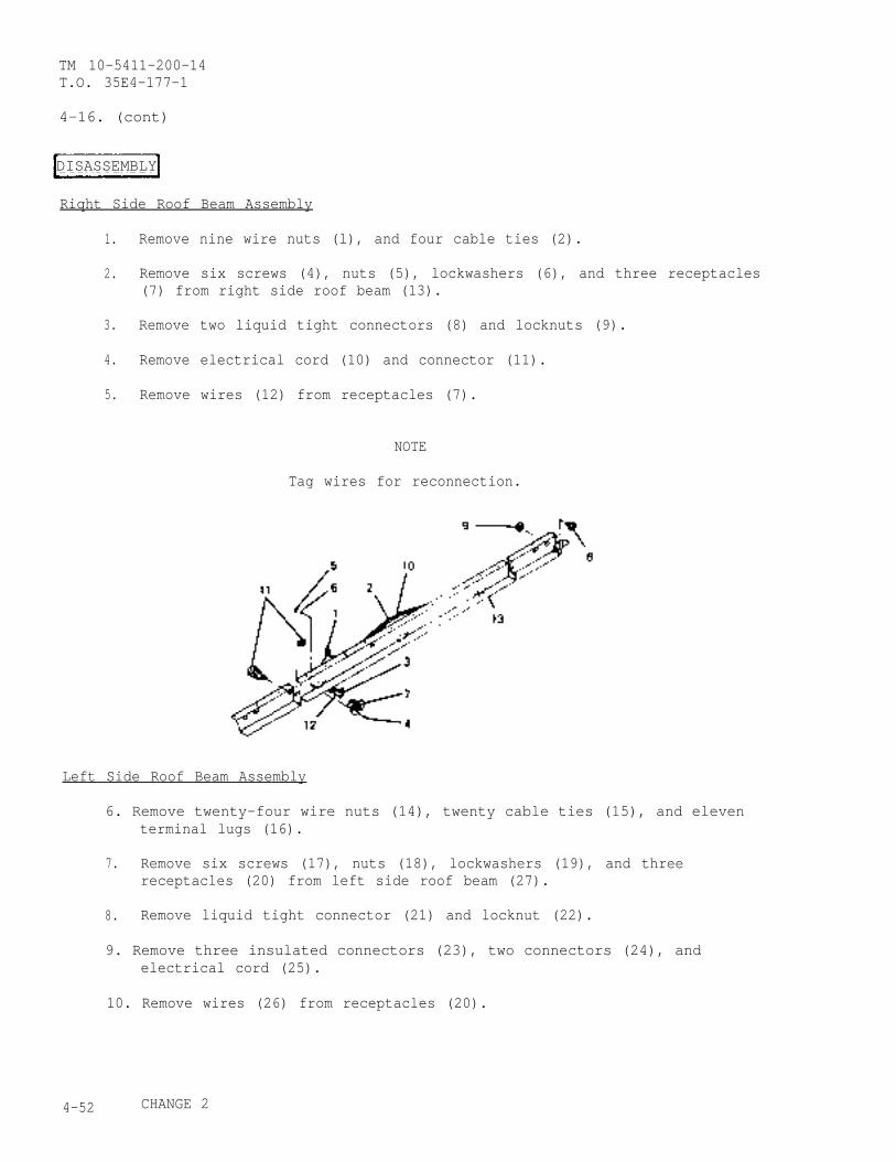
TM 10-5411-200-14T.O. 35E4-177-1
4-16. (cont)
DISASSEMBLY
Riqht Side Roof Beam Assembly
1. Remove nine wire nuts (l), and four cable ties (2).
2. Remove six screws (4), nuts (5), lockwashers (6), and three receptacles(7) from right side roof beam (13).
3. Remove two liquid tight connectors (8) and locknuts (9).
4. Remove electrical cord (10) and connector (11).
5. Remove wires (12) from receptacles (7).
NOTE
Tag wires for reconnection.
Left Side Roof Beam Assembly
6. Remove twenty-four wire nuts (14), twenty cable ties (15), and eleventerminal lugs (16).
7. Remove six screws (17), nuts (18), lockwashers (19), and threereceptacles (20) from left side roof beam (27).
8. Remove liquid tight connector (21) and locknut (22).
9. Remove three insulated connectors (23), two connectors (24), andelectrical cord (25).
10. Remove wires (26) from receptacles (20).
4-52 CHANGE 2
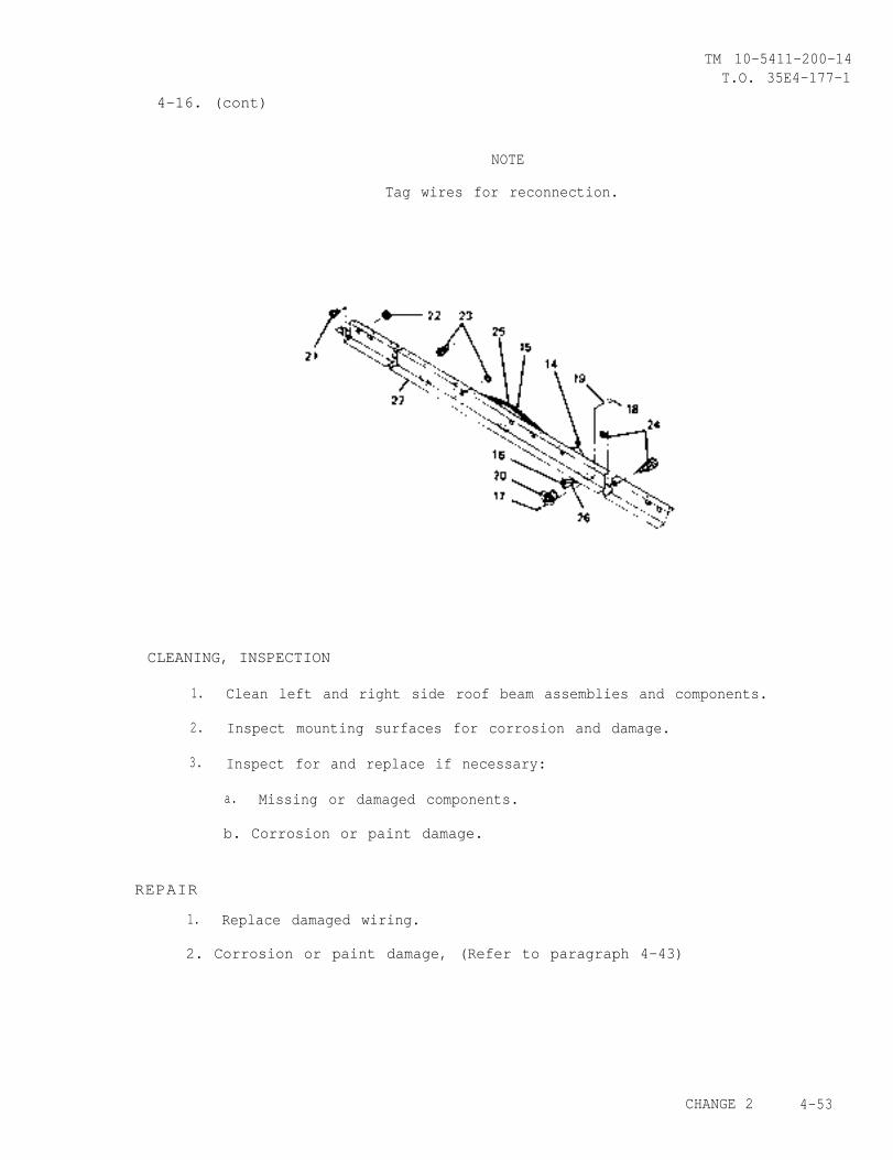
TM 10-5411-200-14T.O. 35E4-177-1
4-16. (cont)
NOTE
Tag wires for reconnection.
CLEANING, INSPECTION
1. Clean left and right side roof beam assemblies and components.
2. Inspect mounting surfaces for corrosion and damage.
3. Inspect for and replace if necessary:
a. Missing or damaged components.
b. Corrosion or paint damage.
REPAIR
1. Replace damaged wiring.
2. Corrosion or paint damage, (Refer to paragraph 4-43)
CHANGE 2 4-53
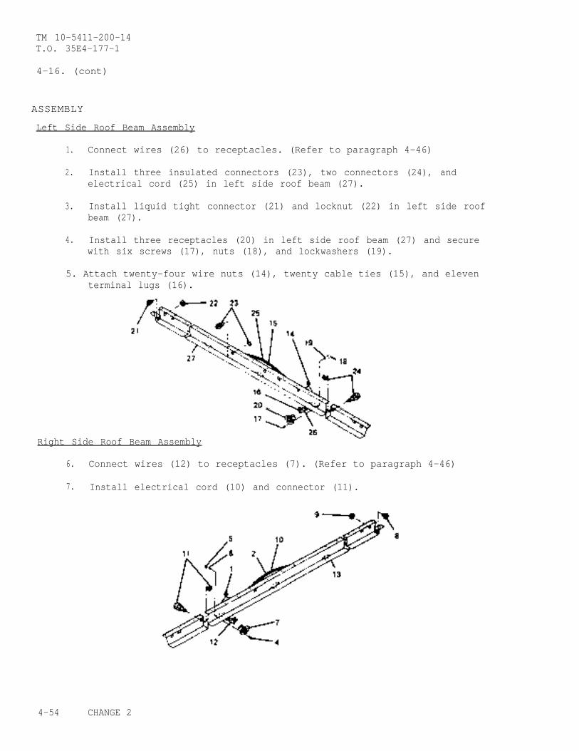
TM 10-5411-200-14T.O. 35E4-177-1
4-16. (cont)
ASSEMBLY
Left Side Roof Beam Assembly
1. Connect wires (26) to receptacles. (Refer to paragraph 4-46)
2. Install three insulated connectors (23), two connectors (24), andelectrical cord (25) in left side roof beam (27).
3. Install liquid tight connector (21) and locknut (22) in left side roofbeam (27).
4. Install three receptacles (20) in left side roof beam (27) and securewith six screws (17), nuts (18), and lockwashers (19).
5. Attach twenty-four wire nuts (14), twenty cable ties (15), and eleventerminal lugs (16).
Right Side Roof Beam Assembly
6. Connect wires (12) to receptacles (7). (Refer to paragraph 4-46)
7. Install electrical cord (10) and connector (11).
4-54 CHANGE 2
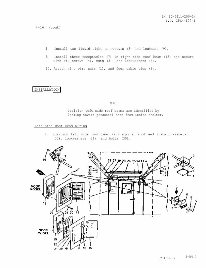
TM 10-5411-200-14T.O. 35E4-177-1
4-16. (cont)
8. Install two liquid tight connectors (8) and locknuts (9).
9. Install three receptacles (7) in right side roof beam (13) and securewith six screws (4), nuts (5), and lockwashers (6).
10. Attach nine wire nuts (l), and four cable ties (2).
INSTALLATION
NOTE
Position left side roof beams are identified bylooking toward personnel door from inside shelter.
Left Side Roof Beam Wirinq
1. Position left side roof beam (23) against roof and install washers(32), lockwashers (31), and bolts (30).
CHANGE 2 4-54.1
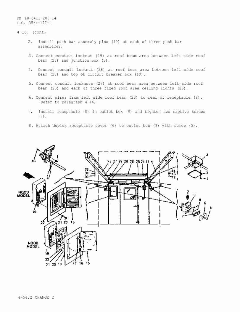
TM 10-5411-200-14T.O. 35E4-177-1
4-16. (cont)
2. Install push bar assembly pins (10) at each of three push barassemblies.
3. Connect conduit locknut (29) at roof beam area between left side roofbeam (23) and junction box (3).
4. Connect conduit locknut (28) at roof beam area between left side roofbeam (23) and top of circuit breaker box (19).
5. Connect conduit locknuts (27) at roof beam area between left side roofbeam (23) and each of three fixed roof area ceiling lights (26).
6. Connect wires from left side roof beam (23) to rear of receptacle (8).(Refer to paragraph 4-46)
7. Install receptacle (8) in outlet box (9) and tighten two captive screws(7).
8. Attach duplex receptacle cover (6) to outlet box (9) with screw (5).
4-54.2 CHANGE 2

TM 10-5411-200-14T.O. 35E4-177-1
4-16. (cont)
9. Connect wires from left side roof beam (23) to each of three fixed roofarea ceiling lights (26). (Refer to paragrapg 4-46.)
10. Attach three fixed roof area ceiling light covers (25) to three fixedarea ceiling lights (26) with nine screws (24).
11. Connect wires from left side roof beam (23) to junction box (3).(Refer to paragraph 4-46)
12. Attach junction box cover (2) to junction box (3) by installing fourscrews (1).
13. Connect wires from left side roof beam (23) to circuit breaker box(19). (Refer to paragraph 4-46)
14. On both models,circuit breaker(21).
15. On model NQOB,
position panelboard (22) over circuit breakers inbox (19) and secure with four screws (20) and washers
install panel cover (18) on the circuit breakerpanelboard (22), move four clamp fingers (17) to the CLOSE position andtighten captive screws (16).
16. Close circuit breaker panel door (15).
Right Side Roof Beam Wiring
1. Position right side roof beam (4) against roof and install washers(14), lockwashers (13), and bolts (12).
2. Connect conduit locknuts (11) between junction box (3) and right sideroof beam (4).
3. Install three push bar assembly pins (10).
4. Connect wires from right side roof beam (4) to rear of two receptacles(8). (Refer to paragraph 4-46)
5. Install two receptacles (8) in two outlet boxes (9) and secure withfour screws (7).
6. Attach receptacle cover (6) to outlet box (9) with screw (5) at eachend of right side roof beam (4).
7. Connect wires from right side roof beam (4) to junction box (3).(Refer to paragraph 4-46)
8. Attach junction box cover (2) to junction box (3) by installing fourscrews (l).
CHANGE 2 4-55
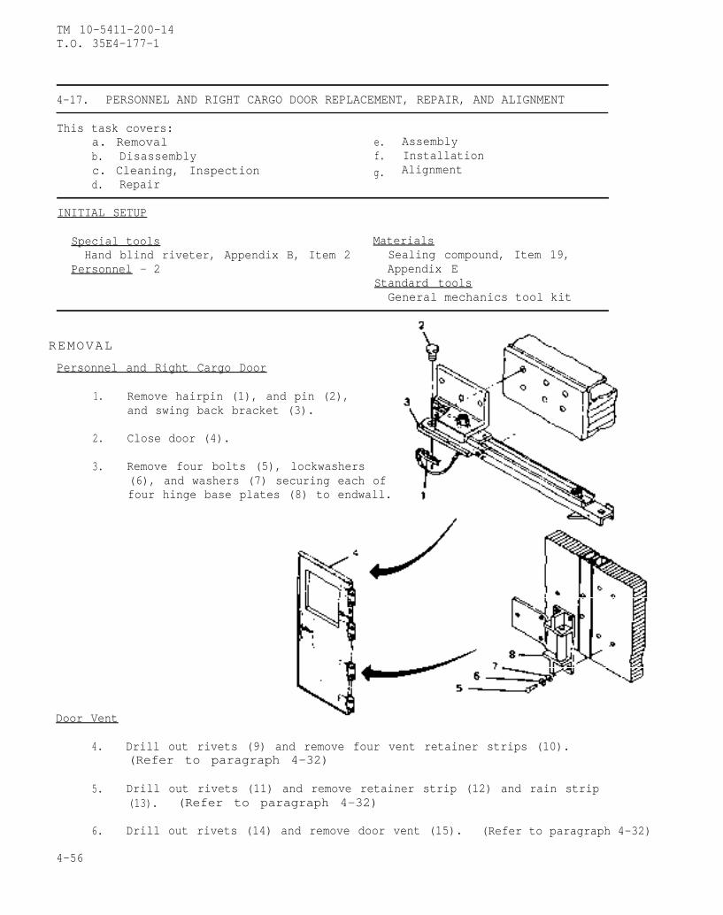
TM 10-5411-200-14T.O. 35E4-177-1
4-17. PERSONNEL AND RIGHT CARGO DOOR REPLACEMENT, REPAIR, AND ALIGNMENT
This task covers:a. Removal e. Assemblyb. Disassembly f. Installationc. Cleaning, Inspection g. Alignmentd. Repair
INITIAL SETUP
Special tools MaterialsHand blind riveter, Appendix B, Item 2 Sealing compound, Item 19,
Personnel - 2 Appendix EStandard toolsGeneral mechanics tool kit
REMOVAL
Personnel and Right Cargo Door
1. Remove hairpin (1), and pin (2),and swing back bracket (3).
2. Close door (4).
3. Remove four bolts (5), lockwashers(6), and washers (7) securing each offour hinge base plates (8) to endwall.
Door Vent
4. Drill out rivets (9) and remove four vent retainer strips (10).(Refer to paragraph 4-32)
5. Drill out rivets (11) and remove retainer strip (12) and rain strip(13). (Refer to paragraph 4-32)
6. Drill out rivets (14) and remove door vent (15). (Refer to paragraph 4-32)
4-56
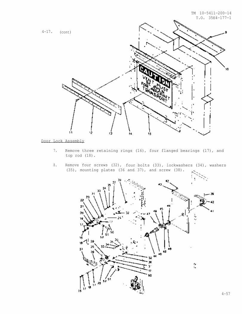
TM 10-5411-200-14T.O. 35E4-177-1
4-17. (cont)
Door Lock Assembly
7. Remove three retaining rings (16), four flanged bearings (17), andtop rod (18).
8. Remove four screws (32), four bolts (33), lockwashers (34), washers(35), mounting plates (36 and 37), and screw (38).
4-57
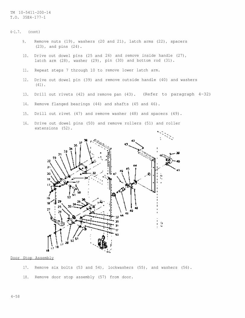
TM 10-5411-200-14T.O. 35E4-177-1
4-1.7. (cont)
9. Remove nuts (19), washers (20 and 21), latch arms (22), spacers(23), and pins (24).
10. Drive out dowel pins (25 andlatch arm (28), washer (29),
11. Repeat steps 7 through 10 to
12. Drive out dowel pin (39) and(41).
26) and remove inside handle (27),pin (30) and bottom rod (31).
remove lower latch arm.
remove outside handle (40) and washers
13. Drill out rivets (42) and remove pan (43). (Refer to paragraph 4-32)
14. Remove flanged bearings (44) and shafts (45 and 46).
15. Drill out rivet (47) and remove washer (48) and spacers (49).
16. Drive out dowel pins (50) and remove rollers (51) and rollerextensions (52).
Door Stop Assembly
17. Remove six bolts (53 and 54), lockwashers (55), and washers (56).
18. Remove door stop assembly (57) from door.
4-58
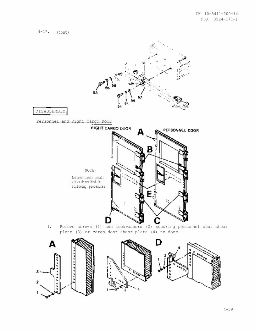
TM 10-5411-200-14T.O. 35E4-177-1
4-17. (cont)
DISASSEMBLY
Personnel and Right Cargo Door
Letters locate detailviews described infollowing procedures.
NOTE
1. Remove screws (1) and lockwashers (2) securing personnel door shearplate (3) or cargo door shear plate (4) to door.
4-59

TM 10-5411-2OO-14T.O. 35E4-177-1
4-17. (cont)
2.
3.
4.
5.
Remove screws (5), lock-washers (6), and washers (7)securing door holder (8) todoor.
Remove bolts (9), lockwashers(10), and washers (11) securinghinge (12) to door.
Remove screws (13) and lock-washers (14) securing jackstorage bracket (15) to door.
Remove screws (16) securing jack support bracket (17) and spacer(18) to door.
Door Vent
6. Remove screws (19), lockwashers (20), and washers (21) securingfilter frame (22) and filter (23) to vent frame (24).
7. Drill out rivet (25) and remove fastener (26). (Refer to paragraph 4-32)
8. Drill out rivets (27) and remove hinge (28). (Refer to paragraph 4-32)
4-60
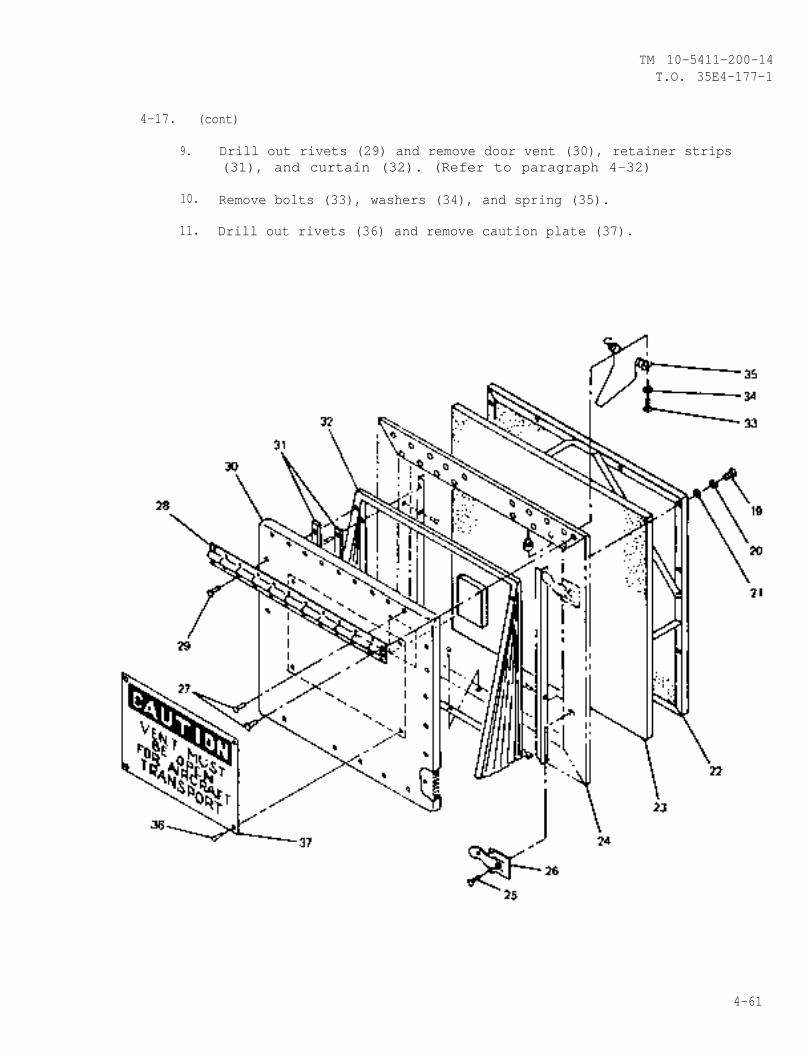
TM 10-5411-200-14T.O. 35E4-177-1
4-17. (cont)
9. Drill out rivets (29) and remove door vent (30), retainer strips(31), and curtain (32). (Refer to paragraph 4-32)
10. Remove bolts (33), washers (34), and spring (35).
11. Drill out rivets (36) and remove caution plate (37).
4-61
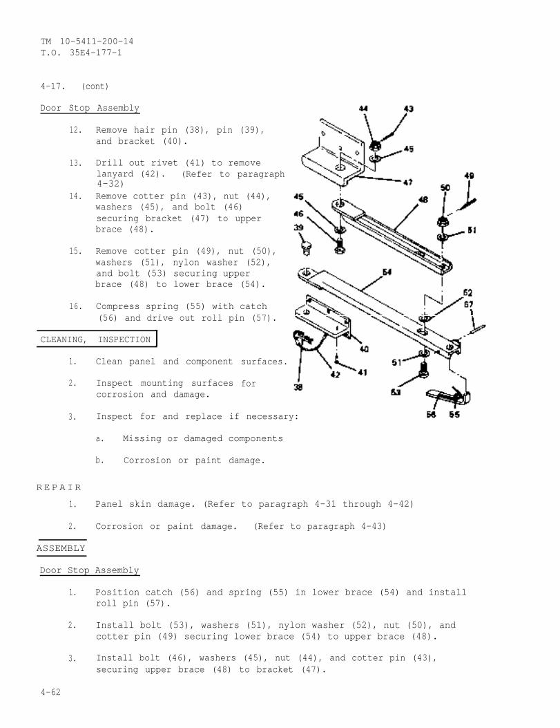
TM 10-5411-200-14T.O. 35E4-177-1
4-17. (cont)
Door Stop Assembly
12. Remove hair pin (38), pin (39),and bracket (40).
13. Drill out rivet (41) to removelanyard (42). (Refer to paragraph4-32)
14. Remove cotter pin (43), nut (44),washers (45), and bolt (46)securing bracket (47) to upperbrace (48).
15. Remove cotter pin (49), nut (50),washers (51), nylon washer (52),and bolt (53) securing upperbrace (48) to lower brace (54).
16. Compress spring (55) with catch(56) and drive out roll pin (57).
CLEANING, INSPECTION
1. surfaces.
2. for
Clean panel and component
Inspect mounting surfacescorrosion and damage.
3.
R E P AIR
1.
2.
Inspect for and replace if necessary:
a. Missing or damaged components
b. Corrosion or paint damage.
Panel skin damage. (Refer to paragraph 4-31 through 4-42)
Corrosion or paint damage. (Refer to paragraph 4-43)
ASSEMBLY
Door Stop Assembly
1. Position catch (56) and spring (55) in lower brace (54) and installroll pin (57).
2. Install bolt (53), washers (51), nylon washer (52), nut (50), andcotter pin (49) securing lower brace (54) to upper brace (48).
3. Install bolt (46), washers (45), nut (44), and cotter pin (43),securing upper brace (48) to bracket (47).
4-62
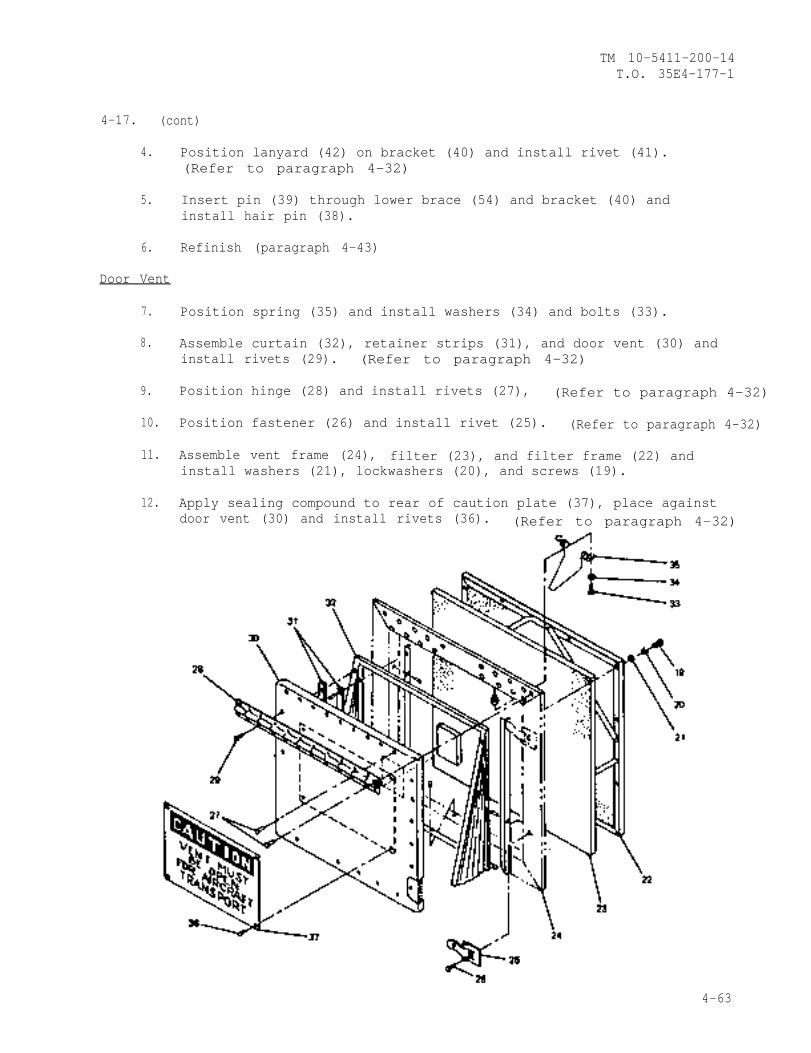
TM 10-5411-200-14T.O. 35E4-177-1
4-17. (cont)
4. Position lanyard (42) on bracket (40) and install rivet (41).(Refer to paragraph 4-32)
5. Insert pin (39) through lower brace (54) and bracket (40) andinstall hair pin (38).
6. Refinish (paragraph 4-43)
Door Vent
7. Position spring (35) and install washers (34) and bolts (33).
8. Assemble curtain (32), retainer strips (31), and door vent (30) andinstall rivets (29). (Refer to paragraph 4-32)
9. Position hinge (28) and install rivets (27), (Refer to paragraph 4-32)
10. Position fastener (26) and install rivet (25). (Refer to paragraph 4-32)
11. Assemble vent frame (24), filter (23), and filter frame (22) andinstall washers (21), lockwashers (20), and screws (19).
12. Apply sealing compound to rear of caution plate (37), place againstdoor vent (30) and install rivets (36). (Refer to paragraph 4-32)
4-63
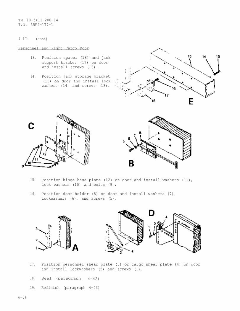
TM 10-5411-200-14T.O. 35E4-177-1
4-17. (cont)
Personnel and Right Cargo Door
13. Position spacer (18) and jacksupport bracket (17) on doorand install screws (16).
14. Position jack storage bracket(15) on door and install lock-washers (14) and screws (13).
15. Position hinge base plate (12) on door and install washers (11),lock washers (10) and bolts (9).
16. Position door holder (8) on door and install washers (7),lockwashers (6), and screws (5),
17. Position personnel shear plate (3) or cargo shear plate (4) on doorand install lockwashers (2) and screws (1).
18. Seal (paragraph 4-42)
19. Refinish (paragraph 4-43)
4-64
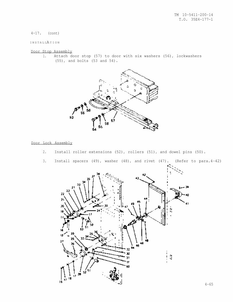
TM 10-5411-200-14T.O. 35E4-177-1
4-17. (cont)
I N S T A L LA T I O N
Door Stop Assembly1. Attach door stop (57) to door with six washers (56), lockwashers
(55), and bolts (53 and 54).
Door Lock Assembly
2. Install roller extensions (52), rollers (51), and dowel pins (50).
3. Install spacers (49), washer (48), and rivet (47). (Refer to para.4-42)
4-65
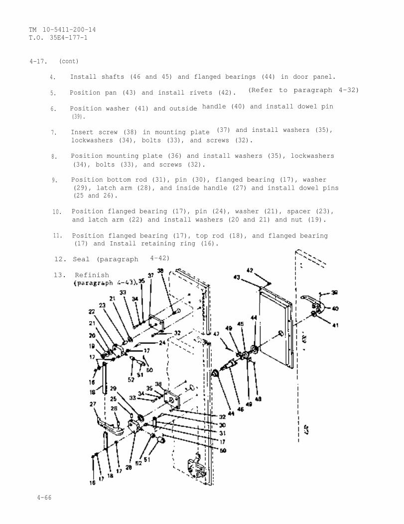
TM 10-5411-200-14T.O. 35E4-177-1
4-17. (cont)
4. Install shafts (46 and 45) and flanged bearings (44) in door panel.
5. Position pan (43) and install rivets (42). (Refer to paragraph 4-32)
6. Position washer (41) and outside handle (40) and install dowel pin(39).
7. Insert screw (38) in mounting plate (37) and install washers (35),lockwashers (34), bolts (33), and screws (32).
8. Position mounting plate (36) and install washers (35), lockwashers(34), bolts (33), and screws (32).
9. Position bottom rod (31), pin (30), flanged bearing (17), washer(29), latch arm (28), and inside handle (27) and install dowel pins(25 and 26).
10. Position flanged bearing (17), pin (24), washer (21), spacer (23),and latch arm (22) and install washers (20 and 21) and nut (19).
11. Position flanged bearing (17), top rod (18), and flanged bearing
13. Refinish
(17) and Install retaining ring (16).
12. Seal (paragraph 4-42)
4-66
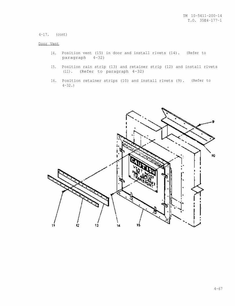
TM 10-5411-200-14T.O. 35E4-177-1
4-17. (cont)
Door Vent
14. Position vent (15) in door and install rivets (14). (Refer toparagraph 4-32)
15. Position rain strip (13) and retainer strip (12) and install rivets(11). (Refer to paragraph 4-32)
16. Position retainer strips (10) and install rivets (9). (Refer to4-32.)
4-67
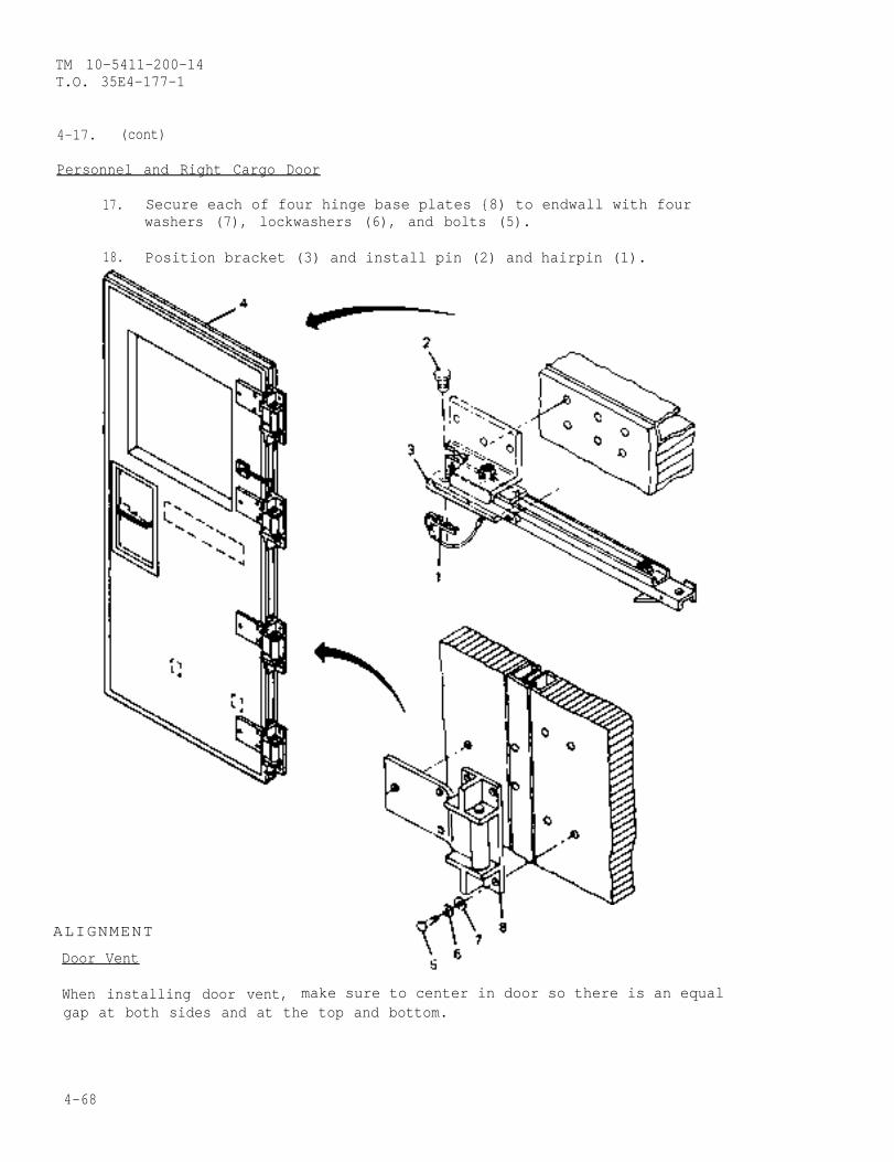
TM 10-5411-200-14T.O. 35E4-177-1
4-17. (cont)
Personnel and Right Cargo Door
17. Secure each of four hinge base plates {8) to endwall with fourwashers (7), lockwashers (6), and bolts (5).
18. Position bracket (3) and install pin (2) and hairpin (1).
ALIGNMENT
Door Vent
When installing door vent, make sure to center in door so there is an equalgap at both sides and at the top and bottom.
4-68
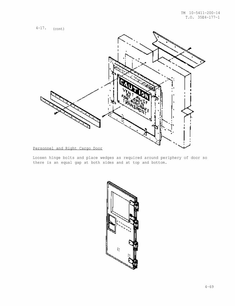
TM 10-5411-200-14T.O. 35E4-177-1
4-17. (cont)
Personnel and Right Cargo Door
Loosen hinge bolts and place wedges as required around periphery of door sothere is an equal gap at both sides and at top and bottom.
4-69
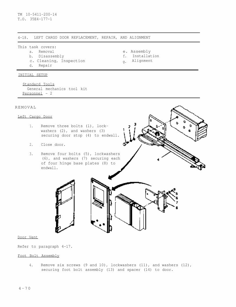
TM 10-5411-200-14T.O. 35E4-177-1
4-18. LEFT CARGO DOOR REPLACEMENT, REPAIR, AND ALIGNMENT
This task covers:a. Removal e. Assemblyb. Disassembly f. Installationc. Cleaning, Inspection g. Alignmentd. Repair
INITIAL SETUP
Standard ToolsGeneral mechanics tool kit
Personnel - 2
REMOVAL
Left Cargo Door
1. Remove three bolts (l), lock-washers (2), and washers (3)securing door stop (4) to endwall.
2. Close door.
3. Remove four bolts (5), lockwashers(6), and washers (7) securing eachof four hinge base plates (8) toendwall.
Door Vent
Refer to paragraph 4-17.
Foot Bolt Assembly
4. Remove six screws (9 and 10), lockwashers (11), and washers (12),securing foot bolt assembly (13) and spacer (14) to door.
4-70
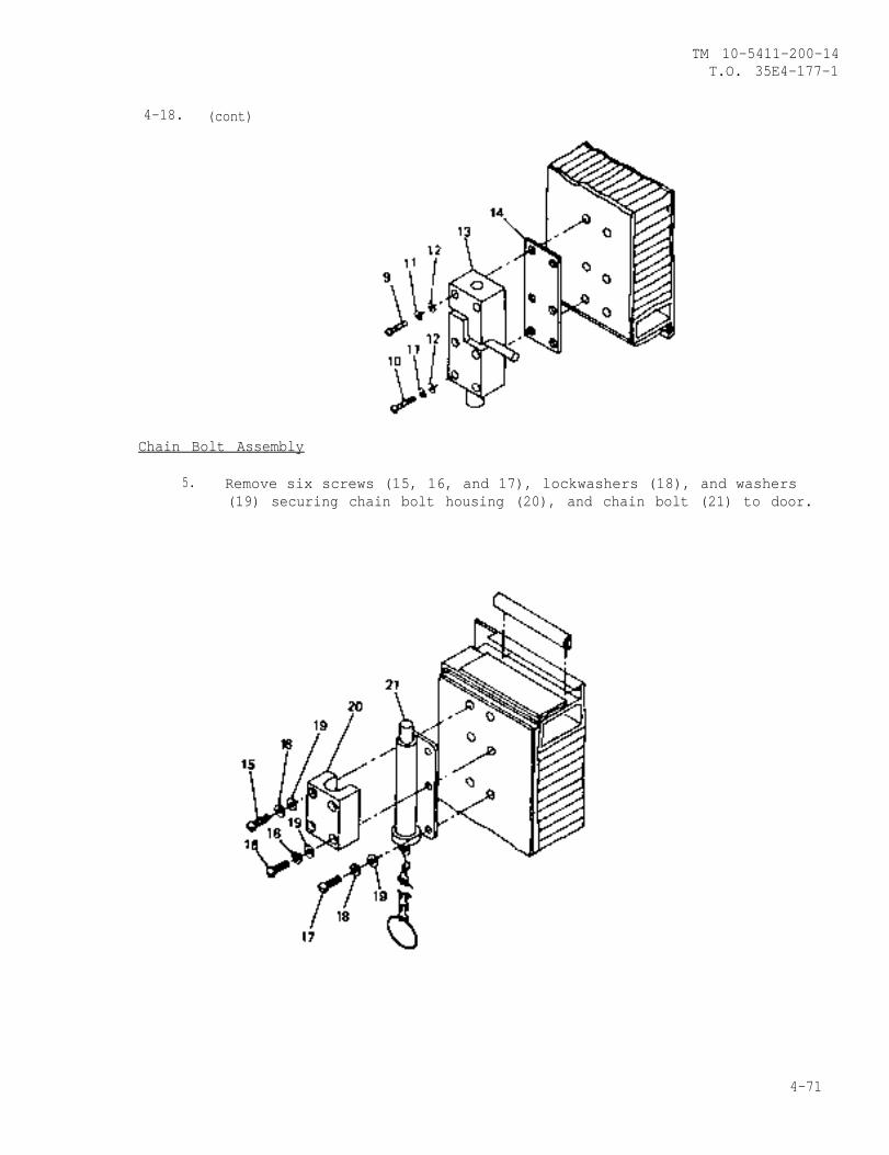
TM 10-5411-200-14T.O. 35E4-177-1
4-18. (cont)
Chain Bolt Assembly
5. Remove six screws (15, 16, and 17), lockwashers (18), and washers(19) securing chain bolt housing (20), and chain bolt (21) to door.
4-71
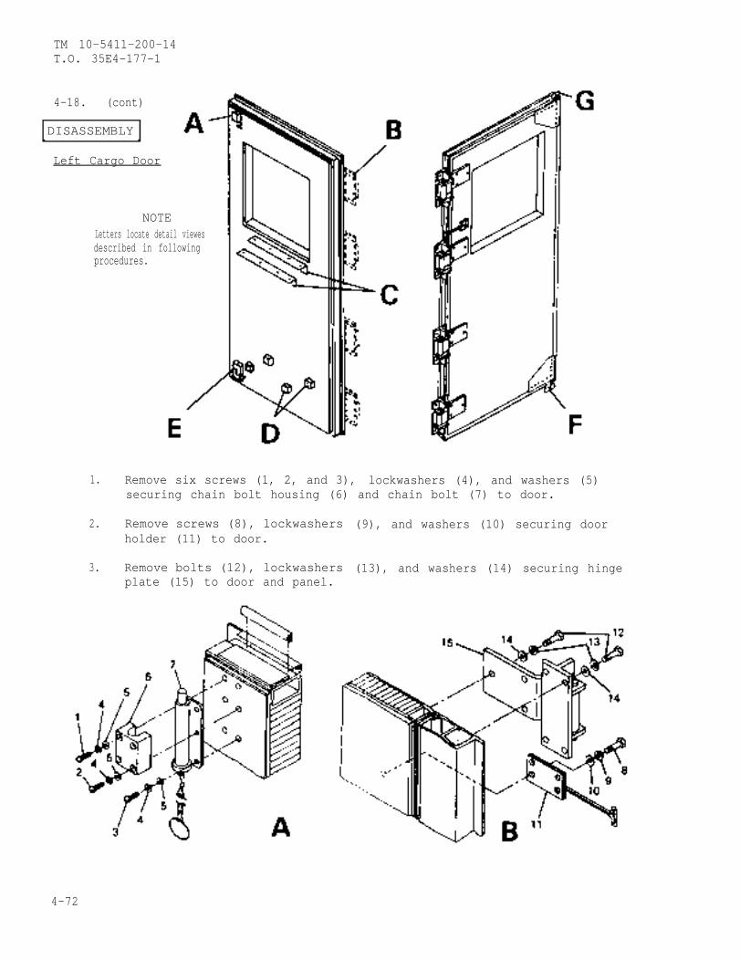
TM 10-5411-200-14T.O. 35E4-177-1
4-18. (cont)
DISASSEMBLY
Left Cargo Door
NOTELetters locate detail viewesdescribed in followingprocedures.
1. Remove six screws (1, 2, and 3), lockwashers (4), and washers (5)securing chain bolt housing (6) and chain bolt (7) to door.
2. Remove screws (8), lockwashersholder (11) to door.
3. Remove bolts (12), lockwashersplate (15) to door and panel.
(9), and washers (10) securing door
(13), and washers (14) securing hinge
4-72
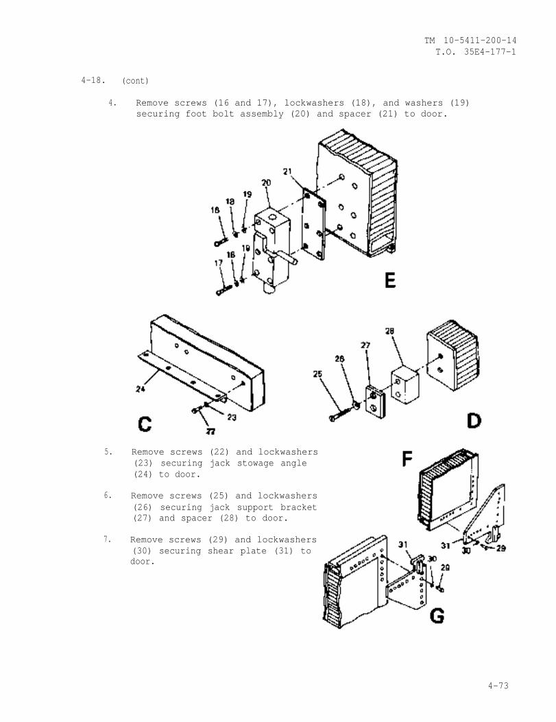
TM 10-5411-200-14T.O. 35E4-177-1
4-18. (cont)
4.
5.
6.
7.
Remove screws (16 and 17), lockwashers (18), and washers (19)securing foot bolt assembly (20) and spacer (21) to door.
Remove screws (22) and lockwashers(23) securing jack stowage angle(24) to door.
Remove screws (25) and lockwashers(26) securing jack support bracket(27) and spacer (28) to door.
Remove screws (29) and lockwashers(30) securing shear plate (31) todoor.
4-73
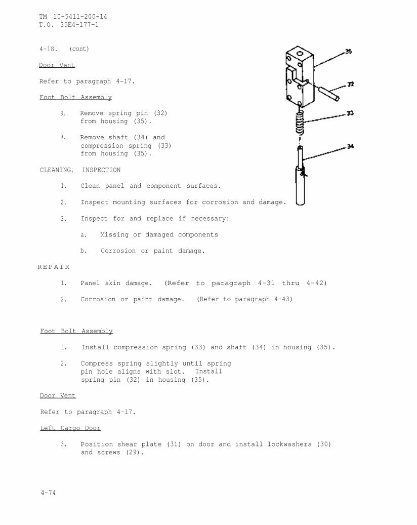
TM 10-5411-200-14T.O. 35E4-177-1
4-18. (cont)
Door Vent
Refer to paragraph 4-17.
Foot Bolt Assembly
8. Remove spring pin (32)from housing (35).
9. Remove shaft (34) andcompression spring (33)from housing (35).
CLEANING, INSPECTION
1. Clean panel and component surfaces.
2. Inspect mounting surfaces for corrosion and damage.
3. Inspect for and replace if necessary:
a. Missing or damaged components
b. Corrosion or paint damage.
REPAIR
1. Panel skin damage. (Refer to paragraph 4-31 thru 4-42)
2. Corrosion or paint damage. (Refer to paragraph 4-43)
Foot Bolt Assembly
1. Install compression spring (33) and shaft (34) in housing (35).
2. Compress spring slightly until springpin hole aligns with slot. Installspring pin (32) in housing (35).
Door Vent
Refer to paragraph 4-17.
Left Cargo Door
3. Position shear plate (31) on door and install lockwashers (30)and screws (29).
4-74
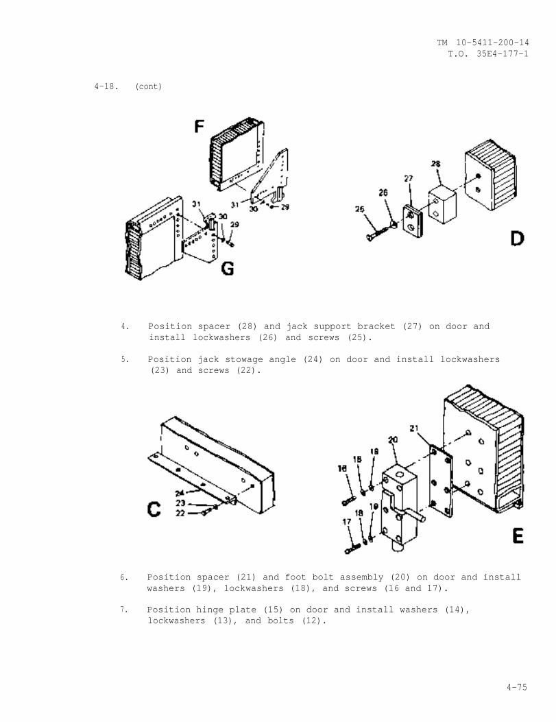
TM 10-5411-200-14T.O. 35E4-177-1
4-18. (cont)
4. Position spacer (28) and jack support bracket (27) on door andinstall lockwashers (26) and screws (25).
5. Position jack stowage angle (24) on door and install lockwashers(23) and screws (22).
6. Position spacer (21) and foot bolt assembly (20) on door and installwashers (19), lockwashers (18), and screws (16 and 17).
7. Position hinge plate (15) on door and install washers (14),lockwashers (13), and bolts (12).
4-75
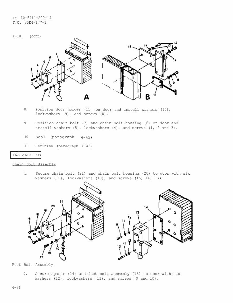
TM 10-5411-200-14T.O. 35E4-177-1
4-18. (cont)
8. Position door holder (11) on door and install washers (10),lockwashers (9), and screws (8).
9. Position chain bolt (7) and chain bolt housing (6) on door andinstall washers (5), lockwashers (4), and screws (1, 2 and 3).
10. Seal (paragraph 4-42)
11. Refinish (paragraph 4-43)
INSTALLATION
Chain Bolt Assembly
1. Secure chain bolt (21) and chain bolt housing (20) to door with sixwashers (19), lockwashers (18), and screws (15, 16, 17).
Foot Bolt Assembly
2. Secure spacer (14) and foot bolt assembly (13) to door with sixwashers (12), lockwashers (11), and screws (9 and 10).
4-76
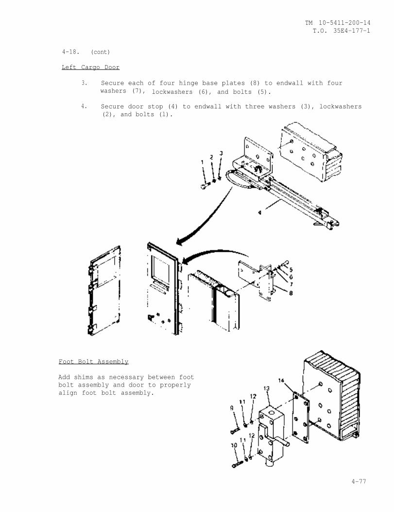
TM 10-5411-200-14T.O. 35E4-177-1
4-18. (cont)
Left Cargo Door
3. Secure each of four hinge base plates (8) to endwall with fourwashers (7), lockwashers (6), and bolts (5).
4. Secure door stop (4) to endwall with three washers (3), lockwashers(2), and bolts (l).
Foot Bolt Assembly
Add shims as necessary between footbolt assembly and door to properlyalign foot bolt assembly.
4-77
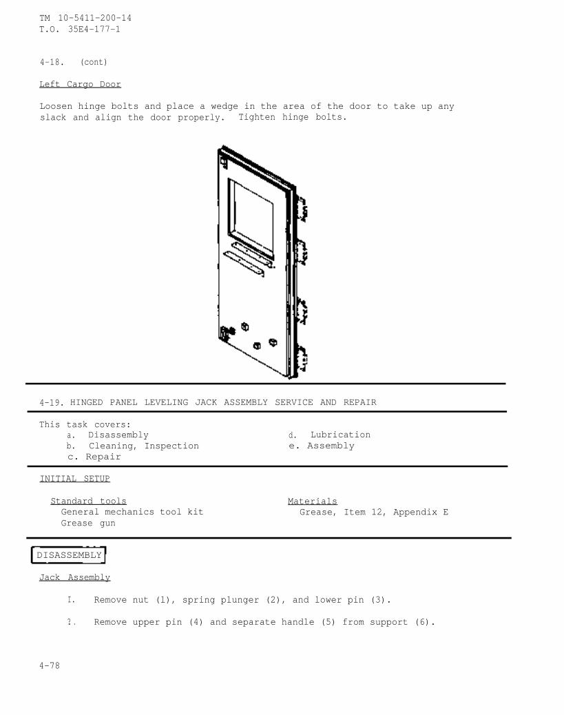
TM 10-5411-200-14T.O. 35E4-177-1
4-18. (cont)
Left Cargo Door
Loosen hinge bolts and place a wedge in the area of the door to take up anyslack and align the door properly. Tighten hinge bolts.
4-19. HINGED PANEL LEVELING JACK ASSEMBLY SERVICE AND REPAIR
This task covers:a. Disassembly d. Lubricationb. Cleaning, Inspection e. Assemblyc. Repair
INITIAL SETUP
Standard tools MaterialsGeneral mechanics tool kit Grease, Item 12, Appendix EGrease gun
DISASSEMBLY
Jack Assembly
I. Remove nut (l), spring plunger (2), and lower pin (3).
?. . Remove upper pin (4) and separate handle (5) from support (6).
4-78
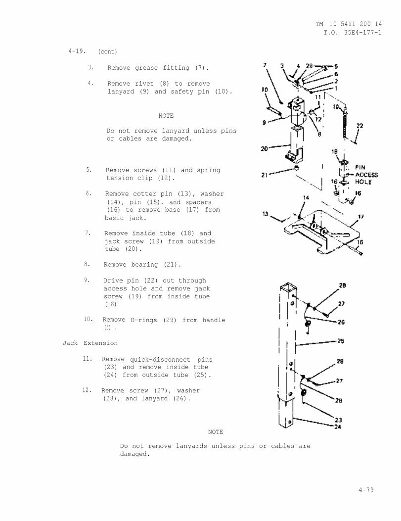
TM 10-5411-200-14T.O. 35E4-177-1
4-19. (cont)
3.
4.
5.
6.
7.
8.
9.
10.
Remove grease fitting (7).
Remove rivet (8) to removelanyard (9) and safety pin (10).
NOTE
Do not remove lanyard unless pinsor cables are damaged.
Remove screws (11) and springtension clip (12).
Remove cotter pin (13), washer(14), pin (15), and spacers(16) to remove base (17) frombasic jack.
Remove inside tube (18) andjack screw (19) from outsidetube (20).
Remove bearing (21).
Drive pin (22) out throughaccess hole and remove jackscrew (19) from inside tube(18)
Remove(5) .
Jack Extension
11. Remove
O-rings (29) from handle
quick-disconnect pins(23) and remove inside tube(24) from outside tube (25).
12. Remove screw (27), washer(28), and lanyard (26).
NOTE
Do not remove lanyards unless pins or cables aredamaged.
4-79
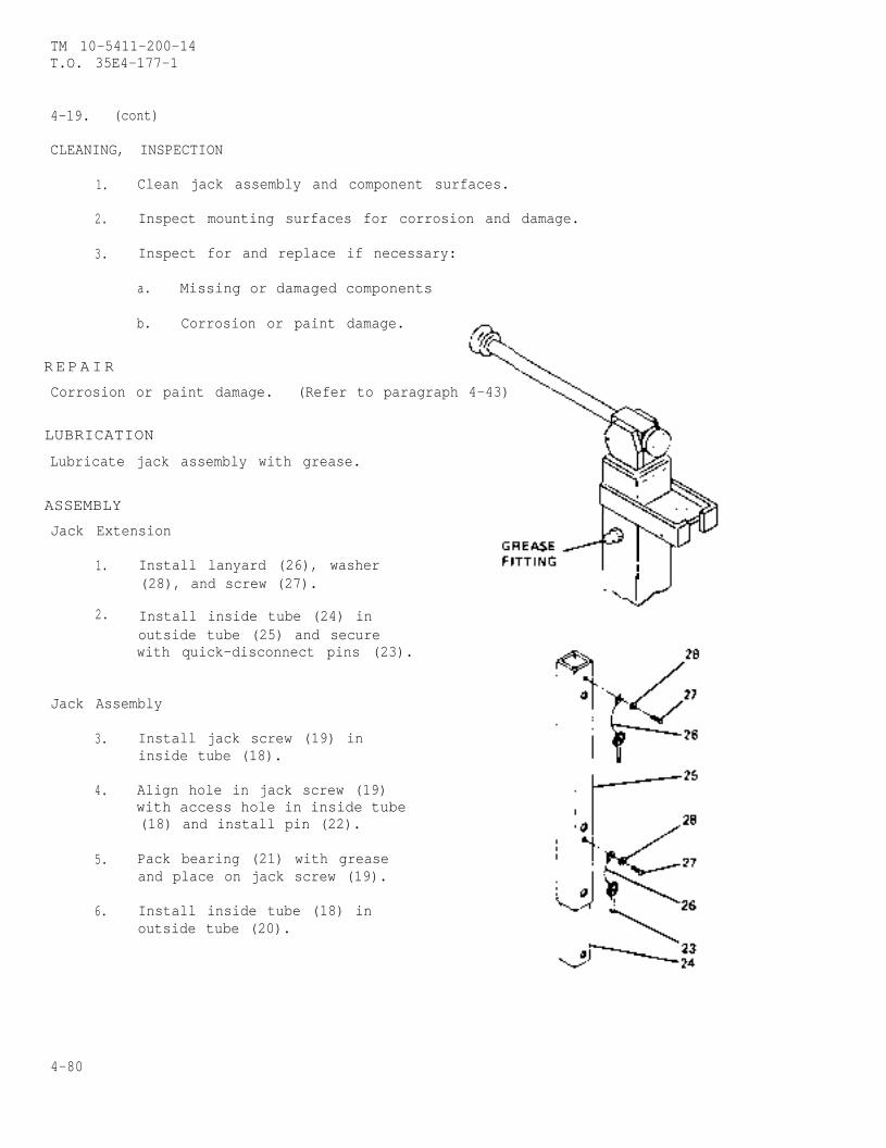
TM 10-5411-200-14T.O. 35E4-177-1
4-19. (cont)
CLEANING, INSPECTION
1. Clean jack assembly and component surfaces.
2. Inspect mounting surfaces for corrosion and damage.
3. Inspect for and replace if necessary:
a. Missing or damaged components
b. Corrosion or paint damage.
R E PAIR
Corrosion or paint damage. (Refer to paragraph 4-43)
LUBRICATION
Lubricate jack assembly with grease.
ASSEMBLY
Jack Extension
1. Install lanyard (26), washer(28), and screw (27).
2. Install inside tube (24) inoutside tube (25) and securewith quick-disconnect pins (23).
Jack Assembly
3.
4.
5.
6.
Install jack screw (19) ininside tube (18).
Align hole in jack screw (19)with access hole in inside tube(18) and install pin (22).
Pack bearing (21) with greaseand place on jack screw (19).
Install inside tube (18) inoutside tube (20).
4-80

TM 10-5411-200-14T.O. 35E4-177-1
4-19. (cont)
7. Position spring tension clip(12) on outside tube (20) andinstall screws (11).
8. Assemble O-rings (29) onhandle (5).
9. Position handle (5) in support(6) and on jack screw (19) withholes in handle yoke and jackscrew aligned. Install pins(3 and 4).
100 Install spring plunger (2) inhandle yoke and secure with nut(1). Adjust nut to controlhandle movement.
11. Position basic jack on base (17)with spacers (16) and secure withpin (15), washer (14), and newcotter pin (13).
12. Install grease fitting (7) andlubricate jack with grease.
4-20. HINGED ROOF PANEL SERVICE, REPLACEMENT, REPAIR, AND ALIGNMENT
This task covers:a. Lubrication e. Repairb. Removal f. Assemblyc. Disassembly g. Installationd. Cleaning, Inspection h. Alignment
INITIAL SETUP
Special Tools Equipment ConditionHand blind riveter, Appendix B, Item 2 Hinged endwalls removed,
Standard Tools paragraph 4-21General mechanics tool kit Hinged roof area ceiling
Personnel - 4 lights removed, paragraph1 Electrician 3-5
MaterialsAdhesive, Item 2, Appendix EAdhesive, Item 3, Appendix ESealant, Item 18, Appendix ESilicone Grease, Item 23, Appendix E
4-81
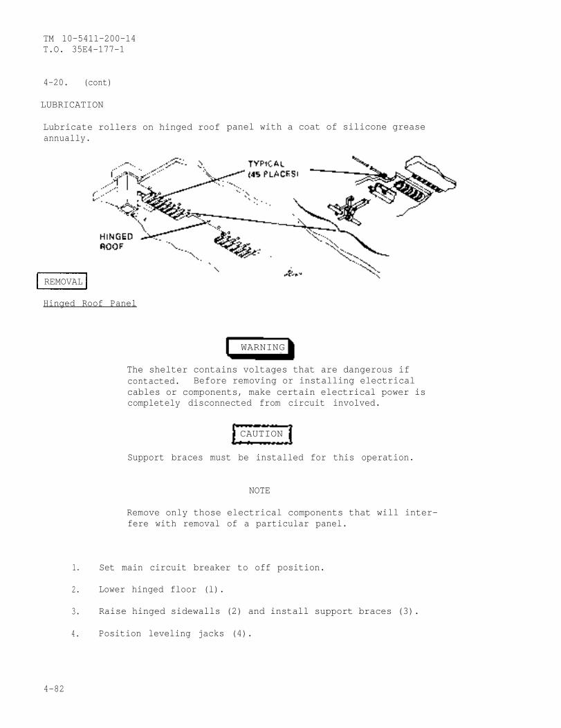
TM 10-5411-200-14T.O. 35E4-177-1
4-20. (cont)
LUBRICATION
Lubricate rollers on hinged roofannually.
panel with a coat of silicone grease
REMOVAL
Hinged Roof Panel
WARNING
The shelter contains voltages that are dangerous ifcontacted. Before removing or installing electricalcables or components, make certain electrical power iscompletely disconnected from circuit involved.
CAUTION
Support braces must be installed for this operation.
NOTE
Remove only those electrical components that will inter-fere with removal of a particular panel.
1. Set main circuit breaker to off position.
2. Lower hinged floor (l).
3. Raise hinged sidewalls (2) and install support braces (3).
4. Position leveling jacks (4).
4-82
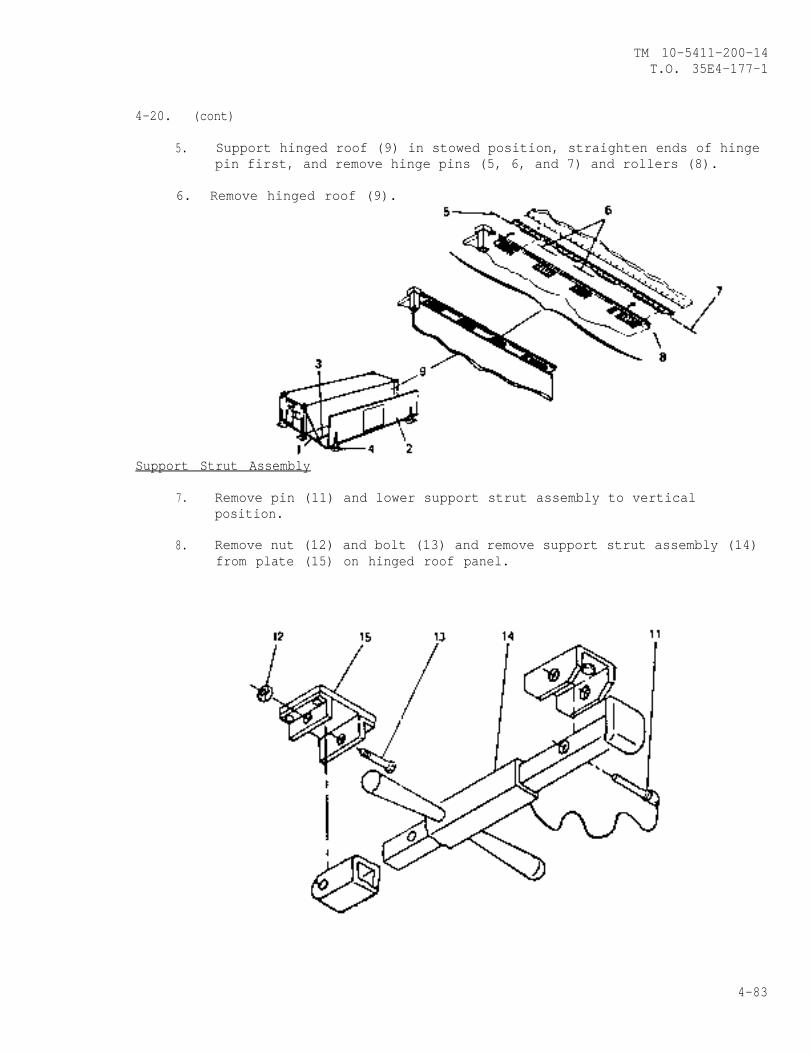
TM 10-5411-200-14T.O. 35E4-177-1
4-20. (cont)
5. Support hinged roof (9) in stowed position, straighten ends of hingepin first, and remove hinge pins (5, 6, and 7) and rollers (8).
6. Remove hinged roof (9).
Support Strut Assembly
7. Remove pin (11) and lower support strut assembly to verticalposition.
8. Remove nut (12) and bolt (13) and remove support strut assembly (14)from plate (15) on hinged roof panel.
4-83
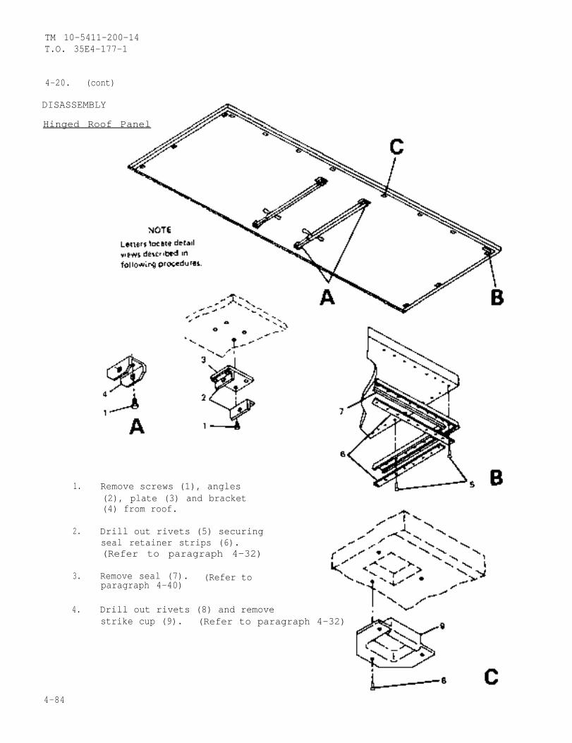
TM 10-5411-200-14T.O. 35E4-177-1
4-20. (cont)
DISASSEMBLY
Hinged Roof Panel
1.
2.
3.
4.
Remove screws (1), angles(2), plate (3) and bracket(4) from roof.
Drill out rivets (5) securingseal retainer strips (6).(Refer to paragraph 4-32)
Remove seal (7). (Refer toparagraph 4-40)
Drill out rivets (8) and removestrike cup (9). (Refer to paragraph 4-32)
4-84
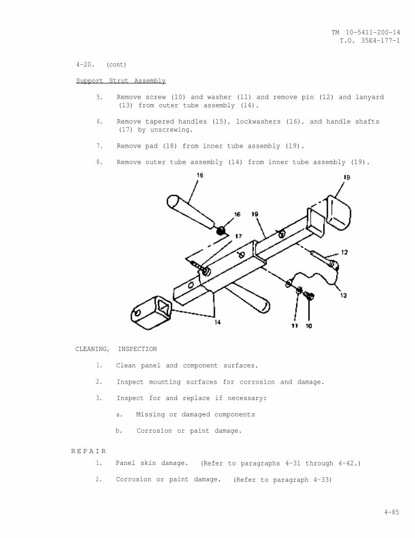
TM 10-5411-200-14T.O. 35E4-177-1
4-20. (cont)
Support Strut Assembly
5. Remove screw (10) and washer (11) and remove pin (12) and lanyard(13) from outer tube assembly (14).
6. Remove tapered handles (15), lockwashers (16), and handle shafts(17) by unscrewing.
7. Remove pad (18) from inner tube assembly (19).
8. Remove outer tube assembly (14) from inner tube assembly (19).
CLEANING, INSPECTION
1. Clean panel and component surfaces.
2. Inspect mounting surfaces for corrosion and damage.
3. Inspect for and replace if necessary:
a. Missing or damaged components
b. Corrosion or paint damage.
R E P A I R
1. Panel skin damage. (Refer to paragraphs 4-31 through 4-42.)
2. Corrosion or paint damage. (Refer to paragraph 4-33)
4-85
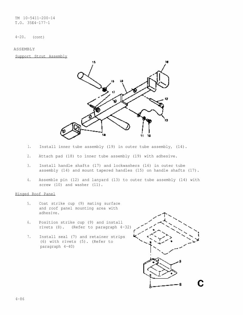
TM 10-5411-200-14T.O. 35E4-177-1
4-20. (cont)
ASSEMBLY
Support Strut Assembly
1. Install inner tube assembly (19) in outer tube assembly, (14).
2. Attach pad (18) to inner tube assembly (19) with adhesive.
3. Install handle shafts (17) and lockwashers (16) in outer tubeassembly (14) and mount tapered handles (15) on handle shafts (17).
4. Assemble pin (12) and lanyard (13) to outer tube assembly (14) withscrew (10) and washer (11).
Hinged Roof Panel
5. Coat strike cup (9) mating surfaceand roof panel mounting area withadhesive.
6. Position strike cup (9) and installrivets (8). (Refer to paragraph 4-32)
7. Install seal (7) and retainer strips(6) with rivets (5). (Refer toparagraph 4-40)
4-86
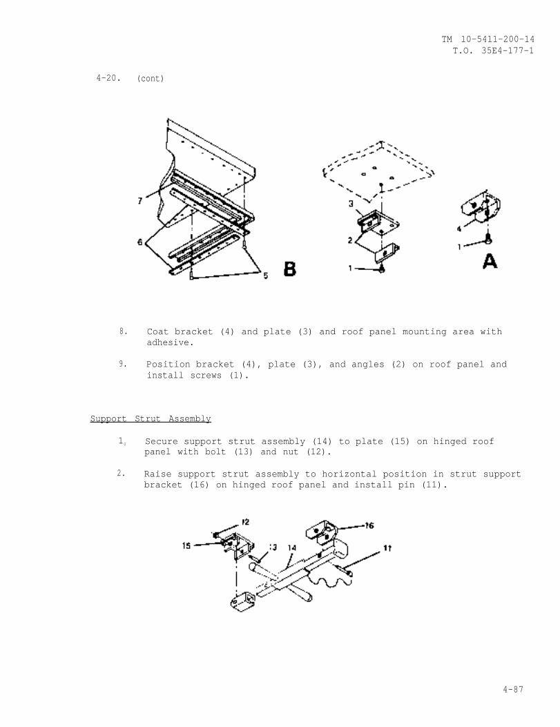
TM 10-5411-200-14T.O. 35E4-177-1
4-20. (cont)
8. Coat bracket (4) and plate (3) and roof panel mounting area withadhesive.
9. Position bracket (4), plate (3), and angles (2) on roof panel andinstall screws (1).
Support Strut Assembly
10 Secure support strut assembly (14) to plate (15) on hinged roofpanel with bolt (13) and nut (12).
2. Raise support strut assembly to horizontal position in strut supportbracket (16) on hinged roof panel and install pin (11).
4-87
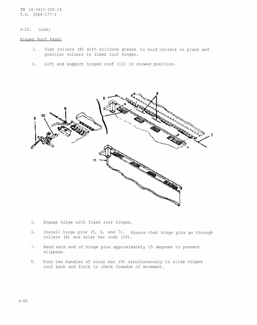
TM 10-5411-200-14T.O. 35E4-177-1
4-20. (cont)
Hinged Roof Panel
3. Coat rollers (8) with silicone grease to hold rollers in place andposition rollers in fixed roof hinges.
4. Lift and support hinged roof (11) in stowed position.
5. Engage hinge with fixed roof hinges.
6. Install hinge pins (5, 6, and 7). Ensure that hinge pins go throughrollers (8) and solar bar rods (10).
7. Bend each end of hinge pins approximately 15 degrees to preventslippage.
8. Push two handles of solar bar (9) simultaneously to slide hingedroof back and forth to check freedom of movement.
4-88
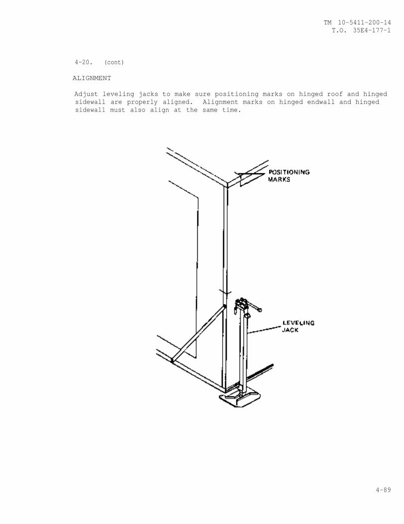
TM 10-5411-200-14T.O. 35E4-177-1
4-20. (cont)
ALIGNMENT
Adjust leveling jacks to make sure positioning marks on hinged roof and hingedsidewall are properly aligned. Alignment marks on hinged endwall and hingedsidewall must also align at the same time.
4-89
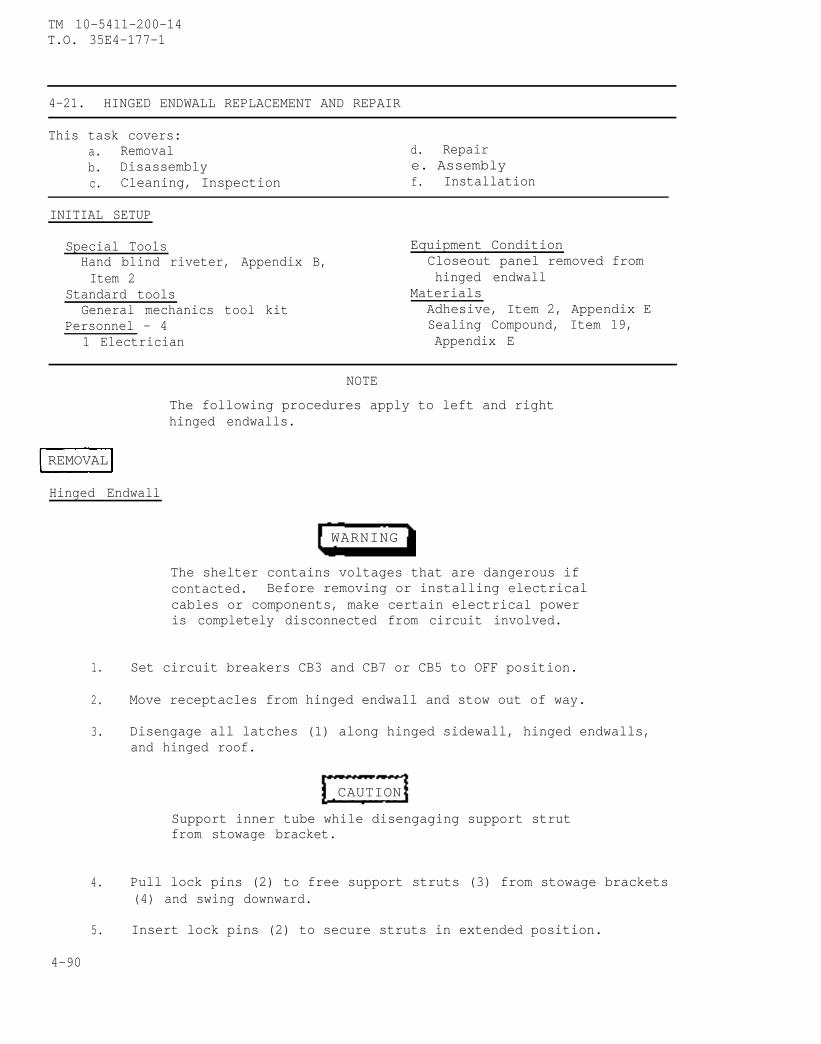
TM 10-5411-200-14T.O. 35E4-177-1
4-21. HINGED ENDWALL REPLACEMENT AND REPAIR
This task covers:a. Removal d. Repairb. Disassembly e. Assemblyc. Cleaning, Inspection f. Installation
INITIAL SETUP
Special Tools Equipment ConditionHand blind riveter, Appendix B, Closeout panel removed fromItem 2 hinged endwall
Standard toolsGeneral mechanics tool kit
MaterialsAdhesive, Item 2, Appendix E
Personnel - 4 Sealing Compound, Item 19,1 Electrician Appendix E
NOTE
The following procedures apply to left and righthinged endwalls.
REMOVAL
Hinged Endwall
WARNING
The shelter contains voltages that are dangerous ifcontacted. Before removing or installing electricalcables or components, make certain electrical poweris completely disconnected from circuit involved.
1. Set circuit breakers CB3 and CB7 or CB5 to OFF position.
2. Move receptacles from hinged endwall and stow out of way.
3. Disengage all latches (1) along hinged sidewall, hinged endwalls,and hinged roof.
CAUTION
Support inner tube while disengaging support strutfrom stowage bracket.
4. Pull lock pins (2) to free support struts (3) from stowage brackets(4) and swing downward.
5. Insert lock pins (2) to secure struts in extended position.
4-90
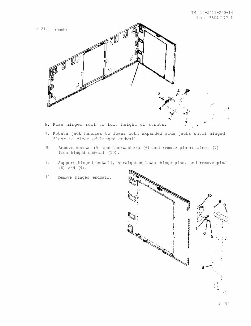
TM 10-5411-200-14T.O. 35E4-177-1
4-21. (cont)
6. Rise hinged roof to ful, height of struts.
7. Rotate jack handles to lower both expanded side jacks until hingedfloor is clear of hinged endwall.
8. Remove screws (5) and lockwashers (6) and remove pin retainer (7)from hinged endwall (10).
9. Support hinged endwall, straighten lower hinge pins, and remove pins(8) and (9).
10. Remove hinged endwall.
4-91
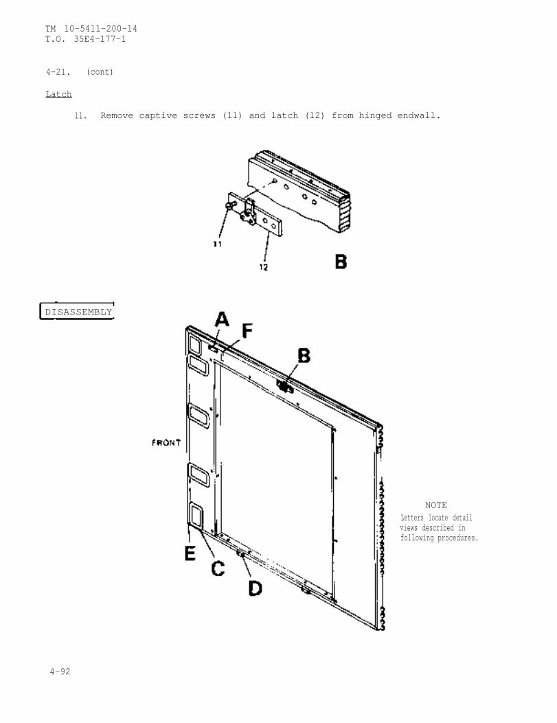
TM 10-5411-200-14T.O. 35E4-177-1
4-21. (cont)
Latch
11. Remove captive screws (11) and latch (12) from hinged endwall.
DISASSEMBLY
NOTELetters locate detailviews described infollowing procedures.
4-92
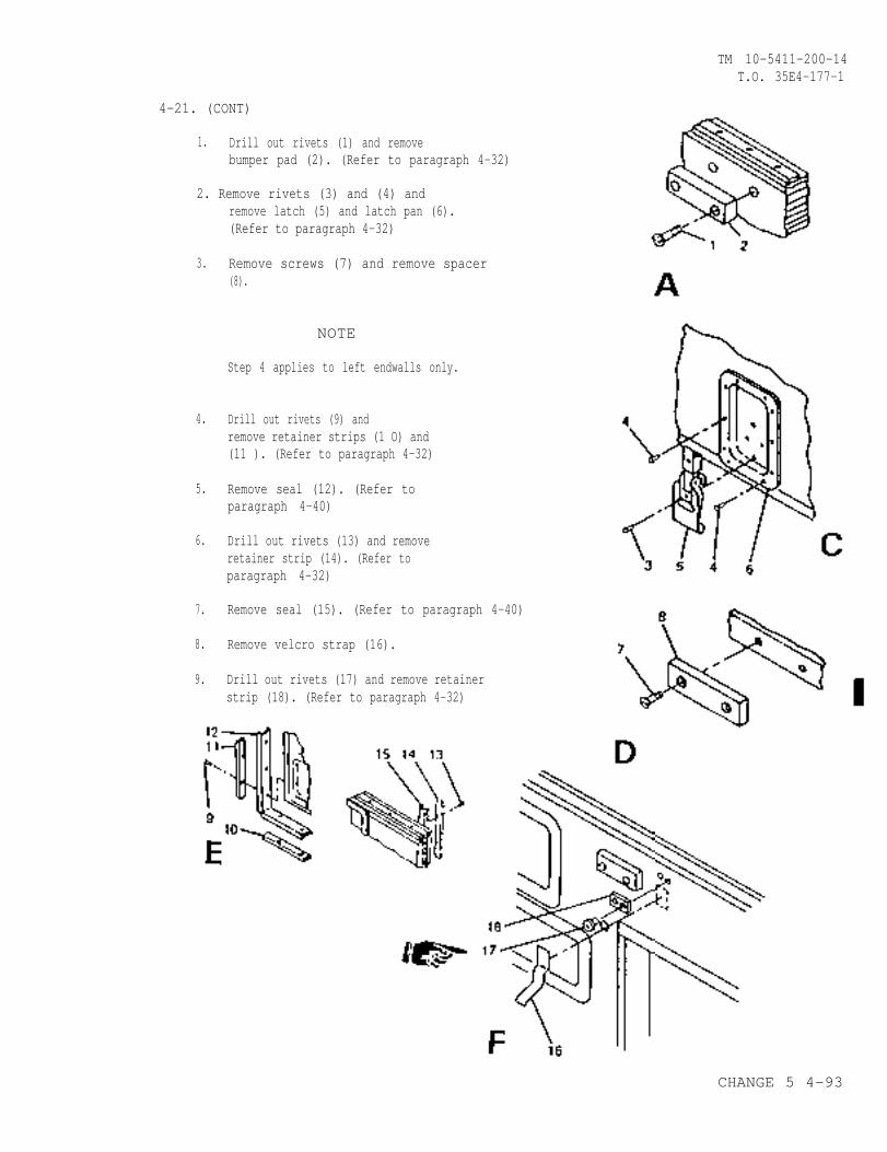
TM 10-5411-200-14T.O. 35E4-177-1
4-21. (CONT)
1. Drill out rivets (1) and removebumper pad (2). (Refer to paragraph 4-32)
2. Remove rivets (3) and (4) andremove latch (5) and latch pan (6).(Refer to paragraph 4-32)
3.
4.
5.
6.
7.
8.
9.
Remove screws (7) and remove spacer(8).
NOTE
Step 4 applies to left endwalls only.
Drill out rivets (9) andremove retainer strips (1 O) and(11 ). (Refer to paragraph 4-32)
Remove seal (12). (Refer toparagraph 4-40)
Drill out rivets (13) and removeretainer strip (14). (Refer toparagraph 4-32)
Remove seal (15). (Refer to paragraph 4-40)
Remove velcro strap (16).
Drill out rivets (17) and remove retainerstrip (18). (Refer to paragraph 4-32)
CHANGE 5 4-93
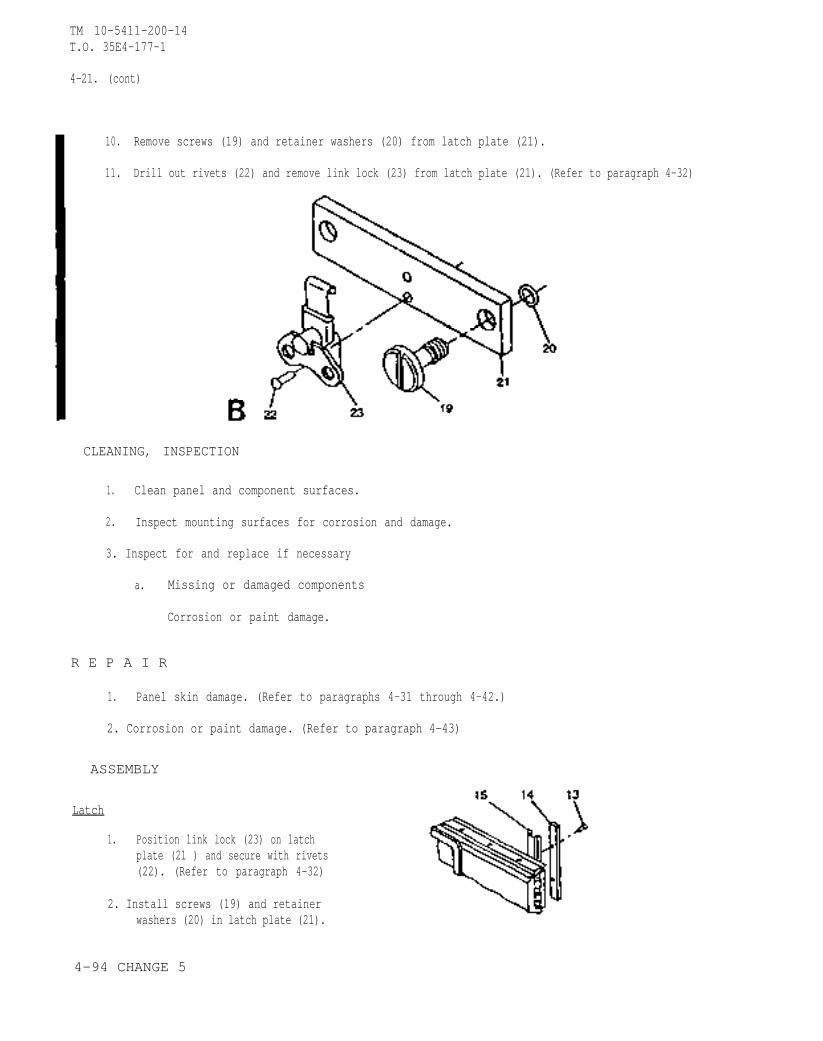
TM 10-5411-200-14T.O. 35E4-177-1
4-21. (cont)
10.
11.
Remove screws (19) and retainer washers (20) from latch plate (21).
Drill out rivets (22) and remove link lock (23) from latch plate (21). (Refer to paragraph 4-32)
CLEANING, INSPECTION
1. Clean panel and component surfaces.
2. Inspect mounting surfaces for corrosion and damage.
3. Inspect for and replace if necessary
a. Missing or damaged components
Corrosion or paint damage.
R E P A I R
1. Panel skin damage. (Refer to paragraphs 4-31 through 4-42.)
2. Corrosion or paint damage. (Refer to paragraph 4-43)
ASSEMBLY
Latch
1. Position link lock (23) on latchplate (21 ) and secure with rivets(22). (Refer to paragraph 4-32)
2. Install screws (19) and retainerwashers (20) in latch plate (21).
4-94 CHANGE 5
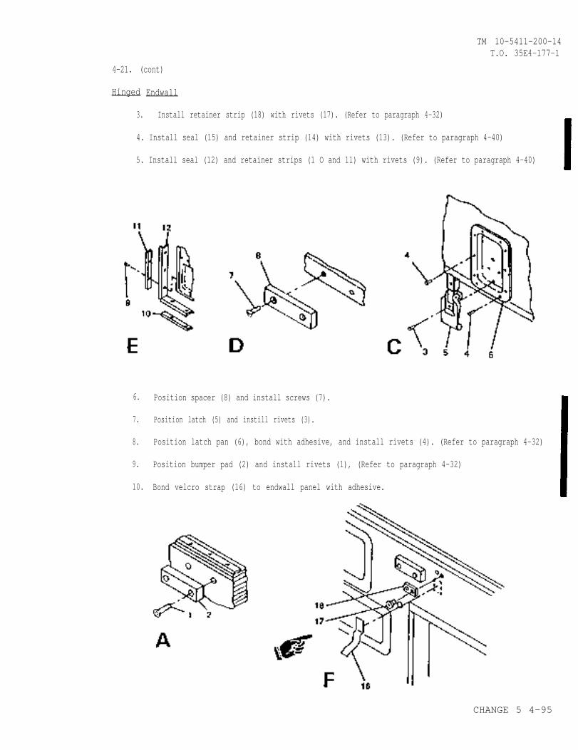
TM 10-5411-200-14T.O. 35E4-177-1
4-21. (cont)
Hinged Endwall
3. Install retainer strip (18) with rivets (17). (Refer to paragraph 4-32)
4. Install seal (15) and retainer strip (14) with rivets (13). (Refer to paragraph 4-40)
5. Install seal (12) and retainer strips (1 O and 11) with rivets (9). (Refer to paragraph 4-40)
6.
7.
8.
9.
10.
Position spacer (8) and install screws (7).
Position latch (5) and instill rivets (3).
Position latch pan (6), bond with adhesive, and install rivets (4). (Refer to paragraph 4-32)
Position bumper pad (2) and install rivets (1), (Refer to paragraph 4-32)
Bond velcro strap (16) to endwall panel with adhesive.
CHANGE 5 4-95
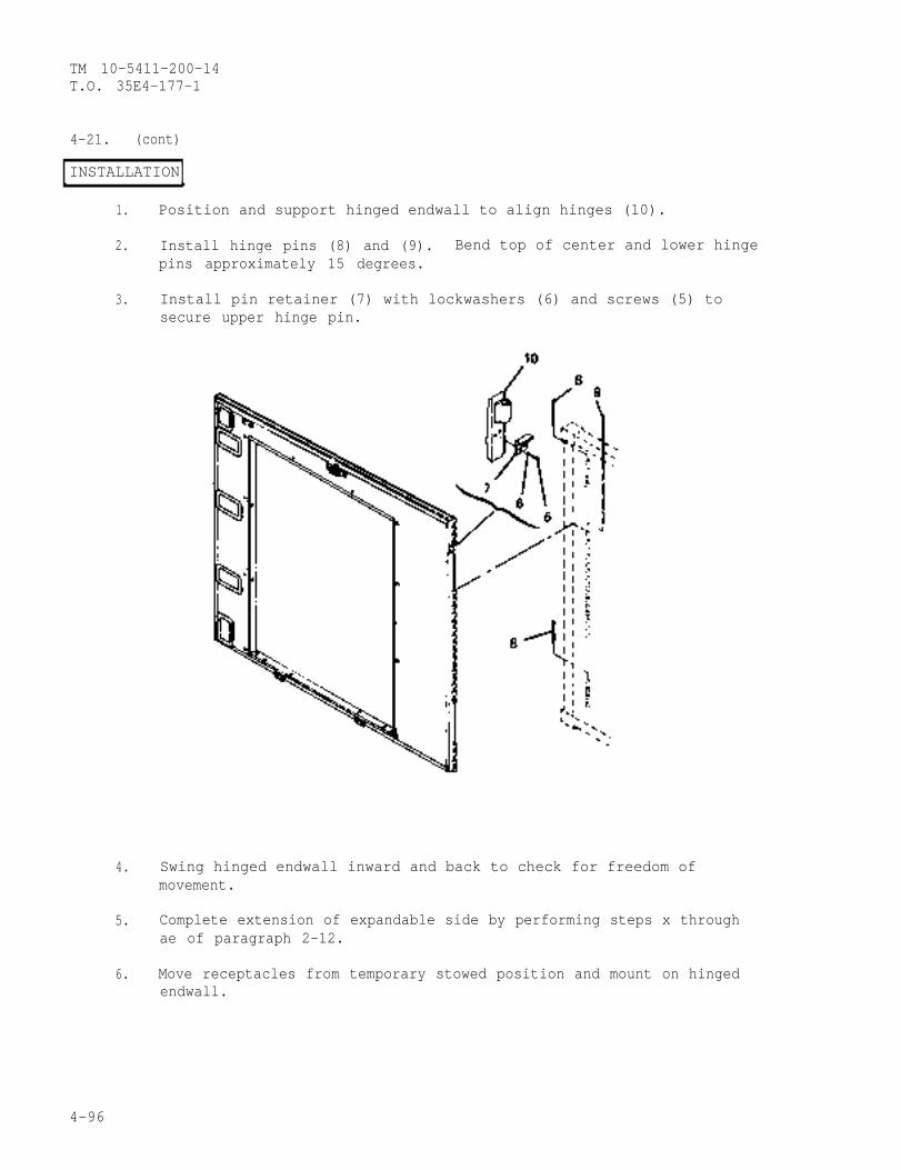
TM 10-5411-200-14T.O. 35E4-177-1
4-21. (cont)
INSTALLATION
1. Position and support hinged endwall to align hinges (10).
2. Install hinge pins (8) and (9). Bend top of center and lower hingepins approximately 15 degrees.
3. Install pin retainer (7) with lockwashers (6) and screws (5) tosecure upper hinge pin.
4. Swing hinged endwall inward and back to check for freedom ofmovement.
5. Complete extension of expandable side by performing steps x throughae of paragraph 2-12.
6. Move receptacles from temporary stowed position and mount on hingedendwall.
4-96
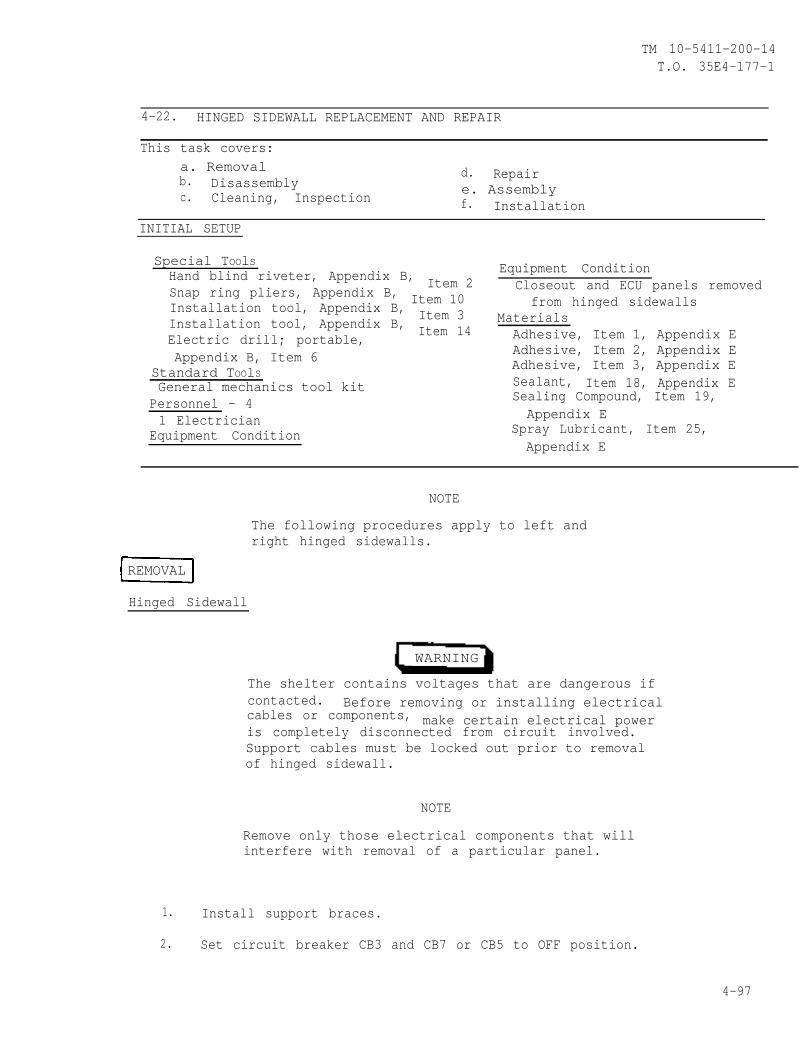
TM 10-5411-200-14T.O. 35E4-177-1
4-22. HINGED SIDEWALL REPLACEMENT AND REPAIR
This task covers:a. Removalb. Disassembly
d. Repair
c. e. AssemblyCleaning, Inspection f. Installation
INITIAL SETUP
Special TOOlSHand blind riveter, Appendix B, Item 2Snap ring pliers, Appendix B, Item 10Installation tool, Appendix B, Item 3Installation tool, Appendix B, Item 14Electric drill; portable,Appendix B, Item 6
Standard TOOlSGeneral mechanics tool kit
Personnel - 41 Electrician
Equipment Condition
Equipment ConditionCloseout and ECU panels removed
from hinged sidewallsMaterialsAdhesive, Item 1, Appendix EAdhesive, Item 2, Appendix EAdhesive, Item 3, Appendix ESealant, Item 18, Appendix ESealing Compound, Item 19,Appendix E
Spray Lubricant, Item 25,Appendix E
NOTE
The following procedures apply to left andright hinged sidewalls.
REMOVAL
Hinged Sidewall
WARNING
The shelter contains voltages that are dangerous ifcontacted. Before removing or installing electricalcables or components, make certain electrical poweris completely disconnected from circuit involved.Support cables must be locked out prior to removalof hinged sidewall.
NOTE
Remove only those electrical components that willinterfere with removal of a particular panel.
1. Install support braces.
2. Set circuit breaker CB3 and CB7 or CB5 to OFF position.
4-97
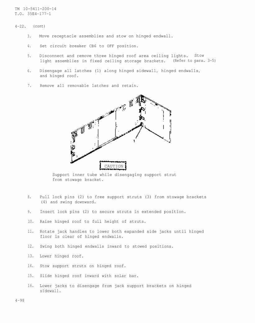
TM 10-5411-200-14T.O. 35E4-177-1
4-22. (cont)
3.
4.
5.
6.
7.
8.
9.
10.
11.
12.
13.
14.
15.
16.
Move receptacle assemblies and stow on hinged endwall.
Set circuit breaker CB6 to OFF position.
Disconnect and remove three hinged roof area ceiling lights. Stowlight assemblies in fixed ceiling storage brackets. (Refer to para. 3-5)
Disengage all latches (1) along hinged sidewall, hinged endwalls,and hinged roof.
Remove all removable latches and retain.
CAUTION
Support inner tube while disengaging support strutfrom stowage bracket.
Pull lock pins (2) to free support struts (3) from stowage brackets(4) and swing downward.
Insert lock pins (2) to secure struts in extended position.
Raise hinged roof to full height of struts.
Rotate jack handles to lower both expanded side jacks until hingedfloor is clear of hinged endwalls.
Swing both hinged endwalls inward to stowed positions.
Lower hinged roof.
Stow support struts on hinged roof.
Slide hinged roof inward with solar bar.
Lower jacks to disengage from jack support brackets on hingedsidewall.
4-98
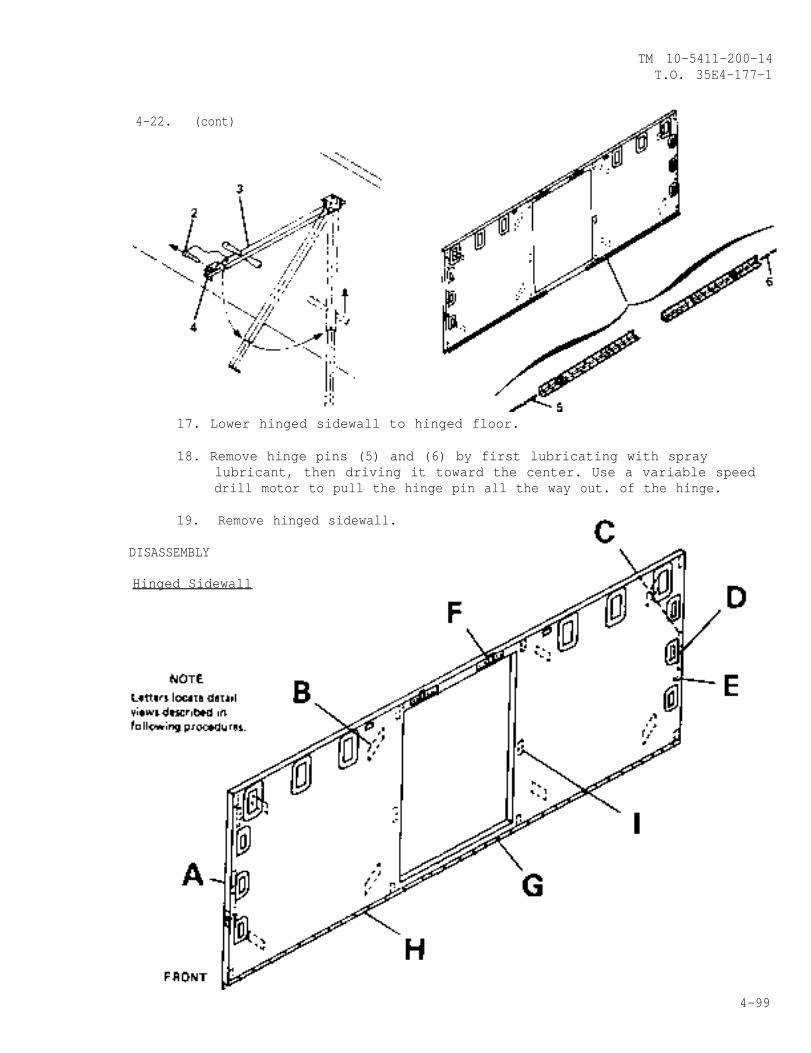
TM 10-5411-200-14T.O. 35E4-177-1
4-22. (cont)
17. Lower hinged sidewall to hinged floor.
18. Remove hinge pins (5) and (6) by first lubricating with spraylubricant, then driving it toward the center. Use a variable speeddrill motor to pull the hinge pin all the way out. of the hinge.
19. Remove hinged sidewall.
DISASSEMBLY
Hinged Sidewall
4-99
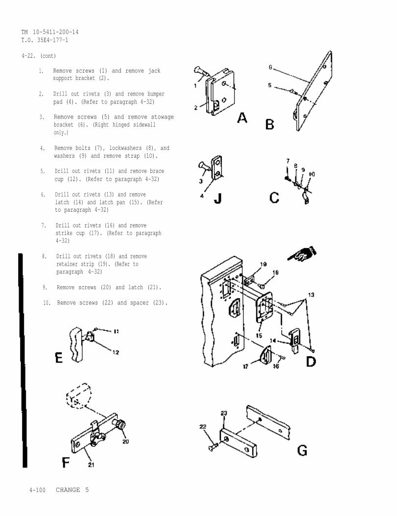
TM 10-5411-200-14T.O. 35E4-177-1
4-22. (cont)
1.
2.
3.
4.
5.
6.
7.
8.
9.
10.
4-100
Remove screws (1) and remove jacksupport bracket (2).
Drill out rivets (3) and remove bumperpad (4). (Refer to paragraph 4-32)
Remove screws (5) and remove stowagebracket (6). (Right hinged sidewallonly.)
Remove bolts (7), lockwashers (8), andwashers (9) and remove strap (1O).
Drill out rivets (11) and remove bracecup (12). (Refer to paragraph 4-32)
Drill out rivets (13) and removelatch (14) and latch pan (15). (Referto paragraph 4-32)
Drill out rivets (16) and removestrike cup (17). (Refer to paragraph4-32)
Drill out rivets (18) and removeretainer strip (19). (Refer toparagraph 4-32)
Remove screws (20) and latch (21).
Remove screws (22) and spacer (23).
CHANGE 5
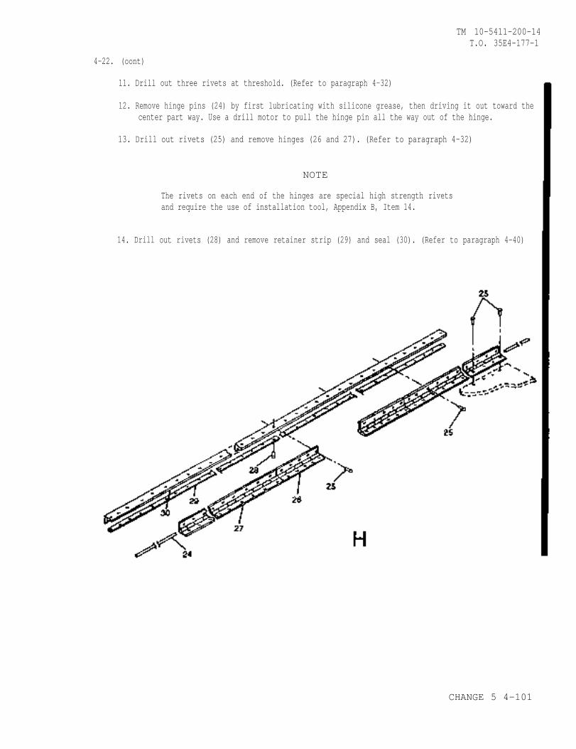
TM 10-5411-200-14T.O. 35E4-177-1
4-22. (oont)
11. Drill out three rivets at threshold. (Refer to paragraph 4-32)
12. Remove hinge pins (24) by first lubricating with silicone grease, then driving it out toward thecenter part way. Use a drill motor to pull the hinge pin all the way out of the hinge.
13. Drill out rivets (25) and remove hinges (26 and 27). (Refer to paragraph 4-32)
NOTE
The rivets on each end of the hinges are special high strength rivetsand require the use of installation tool, Appendix B, Item 14.
14. Drill out rivets (28) and remove retainer strip (29) and seal (30). (Refer to paragraph 4-40)
CHANGE 5 4-101
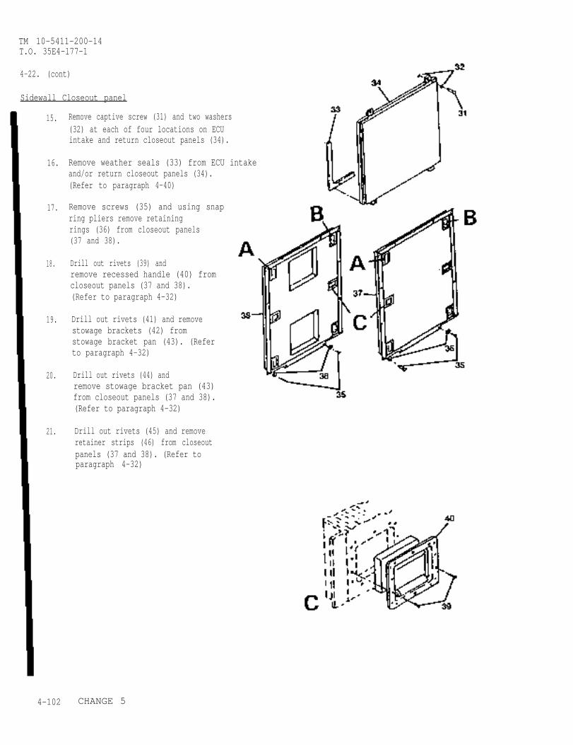
TM 10-5411-200-14T.O. 35E4-177-1
4-22. (cont)
Sidewall Closeout panel
15.
16.
17.
18.
19.
20.
21.
Remove captive screw (31) and two washers(32) at each of four locations on ECUintake and return closeout panels (34).
Remove weather seals (33) from ECU intakeand/or return closeout panels (34).(Refer to paragraph 4-40)
Remove screws (35) and using snapring pliers remove retainingrings (36) from closeout panels(37 and 38).
Drill out rivets (39) andremove recessed handle (40) fromcloseout panels (37 and 38).(Refer to paragraph 4-32)
Drill out rivets (41) and removestowage brackets (42) fromstowage bracket pan (43). (Referto paragraph 4-32)
Drill out rivets (44) andremove stowage bracket pan (43)from closeout panels (37 and 38).(Refer to paragraph 4-32)
Drill out rivets (45) and removeretainer strips (46) from closeoutpanels (37 and 38). (Refer toparagraph 4-32)
4-102 CHANGE 5
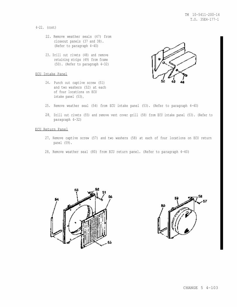
TM 10-5411-200-14T.O. 35E4-177-1
4-22. (cont)
22. Remove weather seals (47) fromcloseout panels (37 and 38).(Refer to paragraph 4-40)
23. Drill out rivets (48) and removeretaining strips (49) from frame(50). (Refer to paragraph 4-32)
ECU Intake Panel
24.
25.
280
Punch out captive screw (51)and two washers (52) at eachof four locations on ECUintake panel (53),
Remove weather seal (54) from ECU intake panel (53). (Refer to paragraph 4-40)
Drill out rivets (55) and remove vent cover grill (58) from ECU intake panel (53). (Refer toparagraph 4-32)
ECU Return Panel
27, Remove captive screw (57) and two washers (58) at each of four locations on ECU returnpanel (59).
28, Remove weather seal (80) from ECU return panel. (Refer to paragraph 4-40)
CHANGE 5 4-103
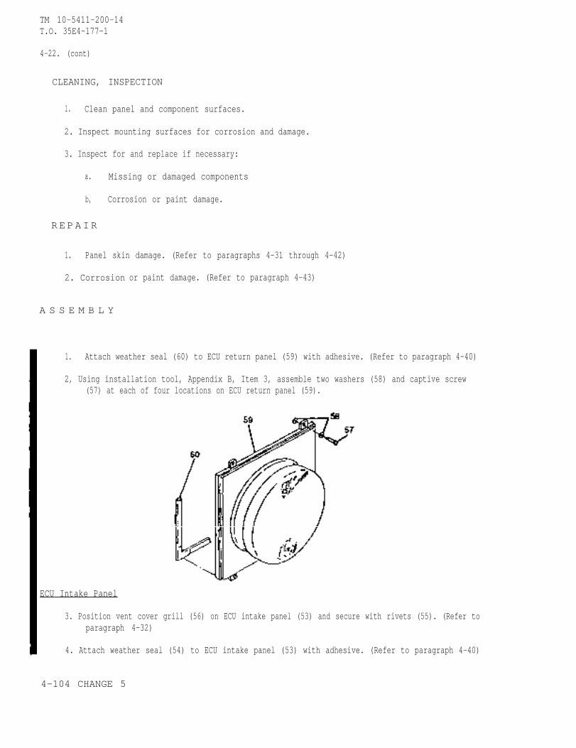
TM 10-5411-200-14T.O. 35E4-177-1
4-22. (cont)
CLEANING, INSPECTION
1. Clean panel and component surfaces.
2. Inspect mounting surfaces for corrosion and damage.
3. Inspect for and replace if necessary:
a. Missing or damaged components
b, Corrosion or paint damage.
R E P AIR
1. Panel skin damage. (Refer to paragraphs 4-31 through 4-42)
2. Corrosion
A S S E M B L Y
or paint damage. (Refer to paragraph 4-43)
1. Attach weather seal (60) to ECU return panel (59) with adhesive. (Refer to paragraph 4-40)
2, Using installation tool, Appendix B, Item 3, assemble two washers (58) and captive screw(57) at each of four locations on ECU return panel (59).
ECU Intake Panel
3. Position vent cover grill (56) on ECU intake panel (53) and secure with rivets (55). (Refer toparagraph 4-32)
4. Attach weather seal (54) to ECU intake panel (53) with adhesive. (Refer to paragraph 4-40)
4-104 CHANGE 5
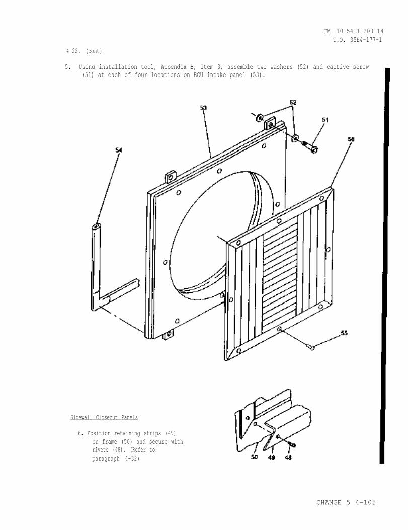
TM 10-5411-200-14T.O. 35E4-177-1
4-22. (cont)
5. Using installation tool, Appendix B, Item 3, assemble two washers (52) and captive screw(51) at each of four locations on ECU intake panel (53).
Sidewall Closeout Panels
6. Position retaining strips (49)on frame (50) and secure withrivets (48). (Refer toparagraph 4-32)
CHANGE 5 4-105
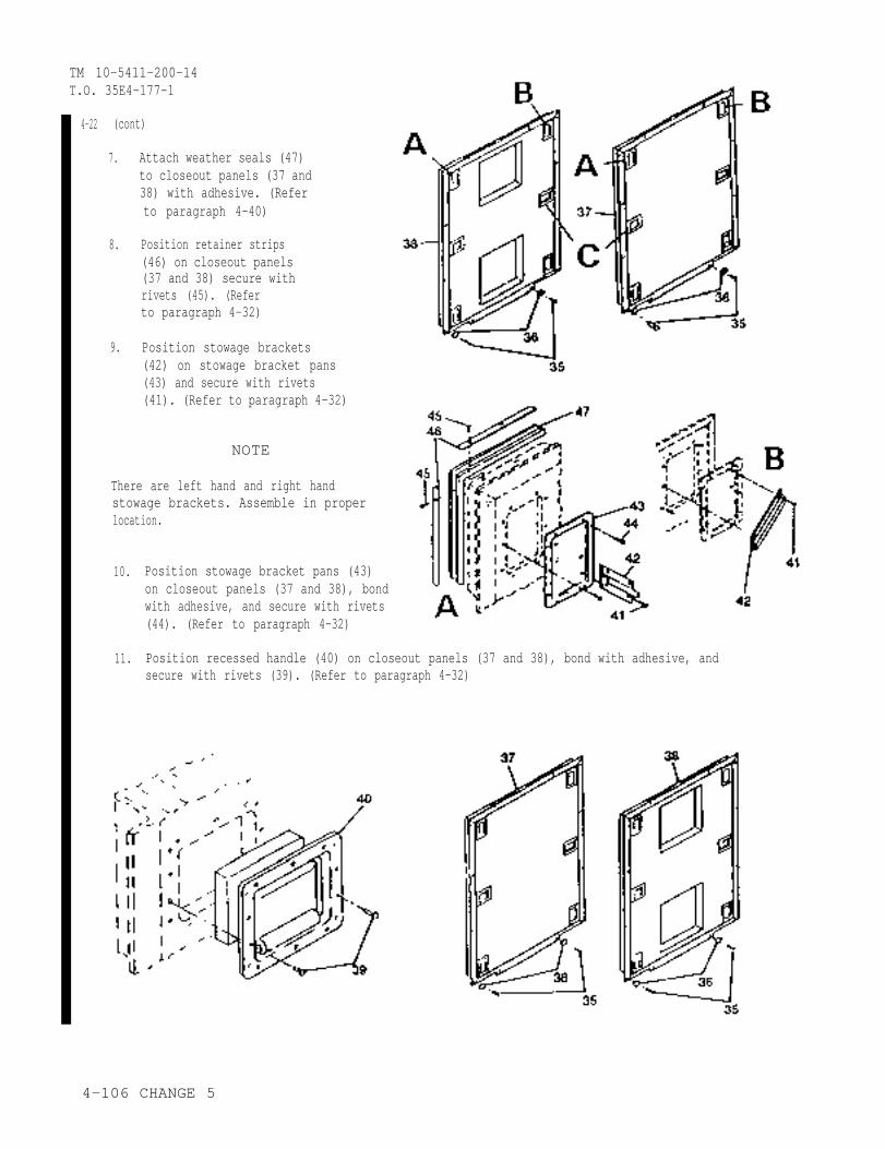
TM 10-5411-200-14T.O. 35E4-177-1
4-22 (cont)
7.
8.
9.
Attach weather seals (47)to closeout panels (37 and38) with adhesive. (Referto paragraph 4-40)
Position retainer strips(46) on closeout panels(37 and 38) secure withrivets (45). (Referto paragraph 4-32)
Position stowage brackets(42) on stowage bracket pans(43) and secure with rivets(41). (Refer to paragraph 4-32)
NOTE
There are left hand and right handstowage brackets. Assemble in properlocation.
10.
11.
Position stowage bracket pans (43)on closeout panels (37 and 38), bondwith adhesive, and secure with rivets(44). (Refer to paragraph 4-32)
Position recessed handle (40) on closeout panels (37 and 38), bond with adhesive, andsecure with rivets (39). (Refer to paragraph 4-32)
4-106 CHANGE 5
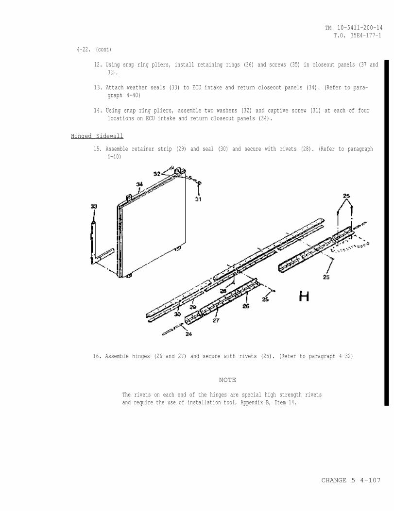
TM 10-5411-200-14T.O. 35E4-177-1
4-22. (cont)
12. Using snap ring pliers, install retaining rings (36) and screws (35) in closeout panels (37 and38).
13. Attach weather seals (33) to ECU intake and return closeout panels (34). (Refer to para-graph 4-40)
14. Using snap ring pliers, assemble two washers (32) and captive screw (31) at each of fourlocations on ECU intake and return closeout panels (34).
Hinged Sidewall
15. Assemble retainer strip (29) and seal (30) and secure with rivets (28). (Refer to paragraph4-40)
16. Assemble hinges (26 and 27) and secure with rivets (25). (Refer to paragraph 4-32)
NOTE
The rivets on each end of the hinges are special high strength rivetsand require the use of installation tool, Appendix B, Item 14.
CHANGE 5 4-107
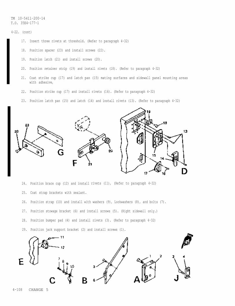
TM 10-5411-200-14T.O. 35E4-177-1
4-22. (cont)
17.
18.
19.
20.
21.
22.
23.
Insert three rivets at threshold. (Refer to paragraph 4-32)
Position spacer (23) and install screws (22).
Position latch (21) and install screws (20).
Position retainer strip (19) and install rivets (18). (Refer to paragraph 4-32)
Coat strike cup (17) and latch pan (15) mating surfaces and sidewall panel mounting areaswith adhesive,
Position strike cup (17) and install rivets (16). (Refer to paragraph 4-32)
Position latch pan (15) and latch (14) and install rivets (13). (Refer to paragraph 4-32)
24.
25.
26.
27.
28.
29.
4-108
Position brace cup (12) and install
Coat strap brackets with sealant.
rivets (11), (Refer to paragraph 4-32)
Position strap (1O) and install with washers (9), Lockwashers (8), and bolts (7).
Position stowage bracket (6) and install screws (5). (Right sidewall only.)
Position bumper pad (4) and install rivets (3). (Refer to paragraph 4-32)
Position jack support bracket (2) and install screws (1).
CHANGE 5
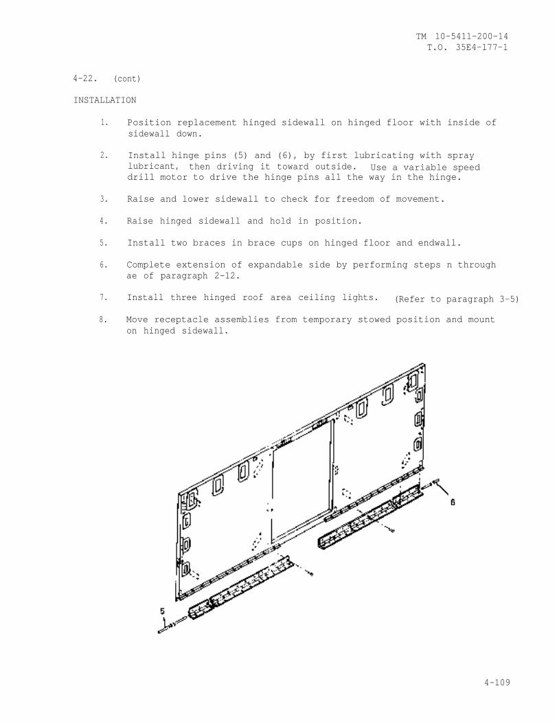
TM 10-5411-200-14T.O. 35E4-177-1
4-22. (cont)
INSTALLATION
1.
2.
3.
4.
5.
6.
7.
8.
Position replacement hinged sidewall on hinged floor with inside ofsidewall down.
Install hinge pins (5) and (6), by first lubricating with spraylubricant, then driving it toward outside. Use a variable speeddrill motor to drive the hinge pins all the way in the hinge.
Raise and lower sidewall to check for freedom of movement.
Raise hinged sidewall and hold in position.
Install two braces in brace cups on hinged floor and endwall.
Complete extension of expandable side by performing steps n throughae of paragraph 2-12.
Install three hinged roof area ceiling lights. (Refer to paragraph 3-5)
Move receptacle assemblies from temporary stowed position and mounton hinged sidewall.
4-109
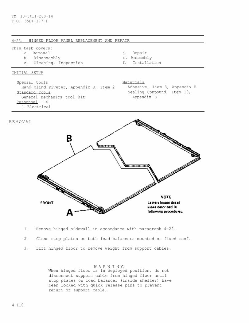
TM 10-5411-200-14T.O. 35E4-177-1
4-23. HINGED FLOOR PANEL REPLACEMENT AND REPAIR
This task covers:a. Removal d. Repairb. Disassembly e. Assemblyc. Cleaning, Inspection f. Installation
INITIAL SETUP
Special tools MaterialsHand blind riveter, Appendix B, Item 2 Adhesive, Item 3, Appendix E
Standard Tools Sealing Compound, Item 19,General mechanics tool kit Appendix E
Personnel - 41 Electrical
REMOVAL
1. Remove hinged sidewall in accordance with paragraph 4-22.
2. Close stop plates on both load balancers mounted on fixed roof.
3. Lift hinged floor to remove weight from support cables.
W A R N I N GWhen hinged floor is in deployed position, do notdisconnect support cable from hinged floor untilstop plates on load balancer (inside shelter) havebeen locked with quick release pins to preventreturn of support cable.
4-110
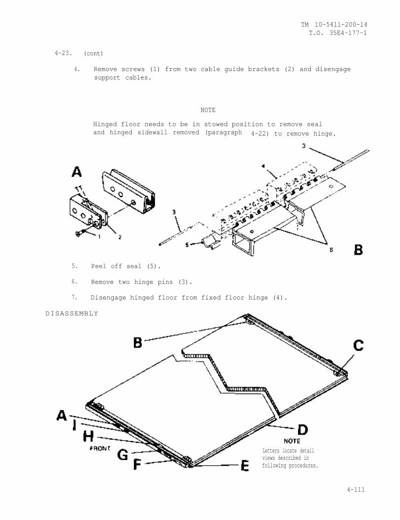
TM 10-5411-200-14T.O. 35E4-177-1
4-23. (cont)
4. Remove screws (1) from two cable guide brackets (2) and disengagesupport cables.
NOTE
Hinged floor needs to be in stowed position to remove sealand hinged sidewall removed (paragraph 4-22) to remove hinge.
5. Peel off seal (5).
6. Remove two hinge pins (3).
7. Disengage hinged floor from fixed floor hinge (4).
DISASSEMBLY
Letters locate detailviews described infollowing procedures.
4-111
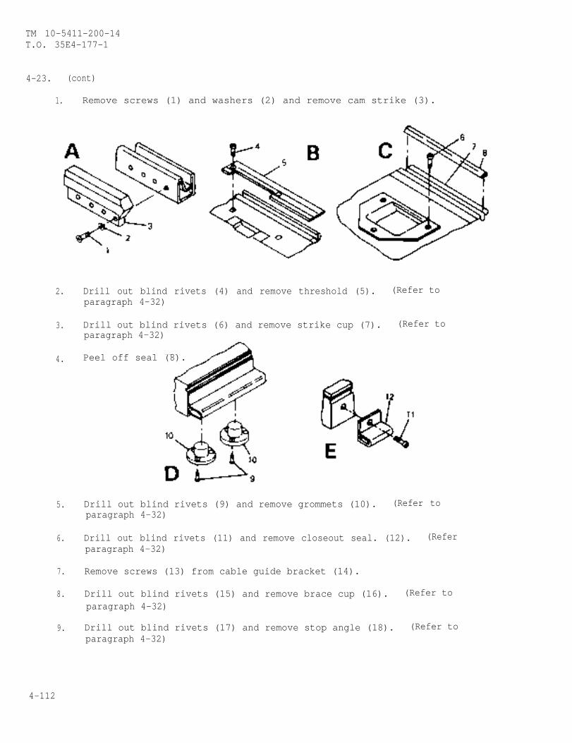
TM 10-5411-200-14T.O. 35E4-177-1
4-23. (cont)
1. Remove screws (1) and washers (2) and remove cam strike (3).
2.
3.
4.
5.
6.
7.
8.
9.
Drill out blind rivets (4) and remove threshold (5). (Refer toparagraph 4-32)
Drill out blind rivets (6) and remove strike cup (7). (Refer toparagraph 4-32)
Peel off seal (8).
Drill out blind rivets (9) and remove grommets (10). (Refer toparagraph 4-32)
Drill out blind rivets (11) and remove closeout seal. (12). (Referparagraph 4-32)
Remove screws (13) from cable guide bracket (14).
Drill out blind rivets (15) and remove brace cup (16). (Refer toparagraph 4-32)
Drill out blind rivets (17) and remove stop angle (18). (Refer toparagraph 4-32)
4-112
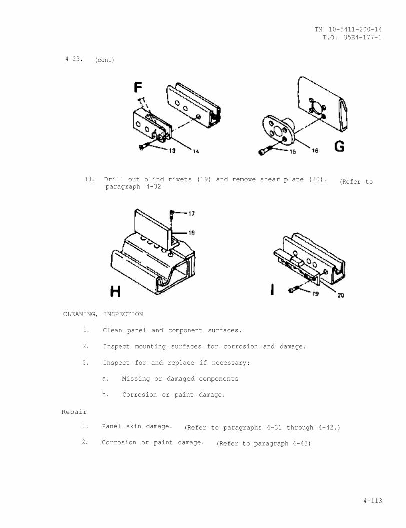
TM 10-5411-200-14T.O. 35E4-177-1
4-23. (cont)
10. Drill out blind rivets (19) and remove shear plate (20). (Refer toparagraph 4-32
CLEANING, INSPECTION
1. Clean panel and component surfaces.
2. Inspect mounting surfaces for corrosion and damage.
3. Inspect for and replace if necessary:
a. Missing or damaged components
b. Corrosion or paint damage.
Repair
1. Panel skin damage. (Refer to paragraphs 4-31 through 4-42.)
2. Corrosion or paint damage. (Refer to paragraph 4-43)
4-113
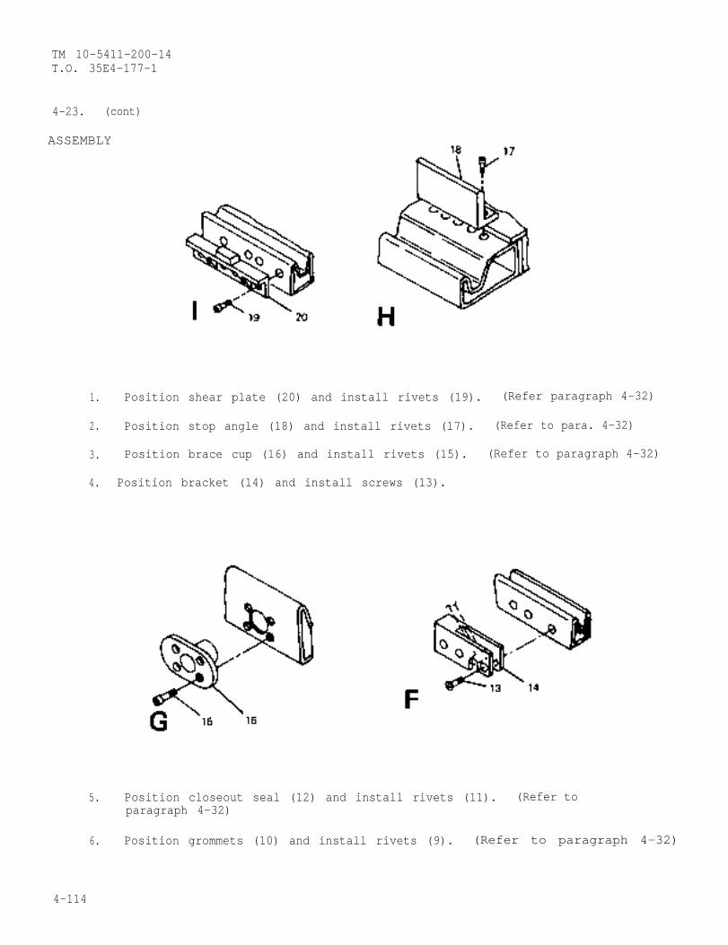
TM 10-5411-200-14T.O. 35E4-177-1
4-23. (cont)
ASSEMBLY
1. Position shear plate (20) and install rivets (19). (Refer paragraph 4-32)
2. Position stop angle (18) and install rivets (17). (Refer to para. 4-32)
3. Position brace cup (16) and install rivets (15). (Refer to paragraph 4-32)
4. Position bracket (14) and install screws (13).
5. Position closeout seal (12) and install rivets (11). (Refer toparagraph 4-32)
6. Position grommets (10) and install rivets (9). (Refer to paragraph 4-32)
4-114
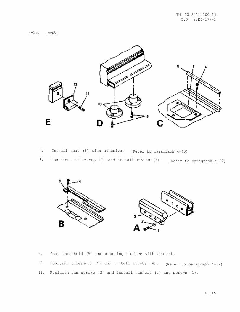
TM 10-5411-200-14T.O. 35E4-177-1
4-23. (cont)
7. Install seal (8) with adhesive. (Refer to paragraph 4-40)
8. Position strike cup (7) and install rivets (6). (Refer to paragraph 4-32)
9. Coat threshold (5) and mounting surface with sealant.
10. Position threshold (5) and install rivets (4). (Refer to paragraph 4-32)
11. Position cam strike (3) and install washers (2) and screws (1).
4-115
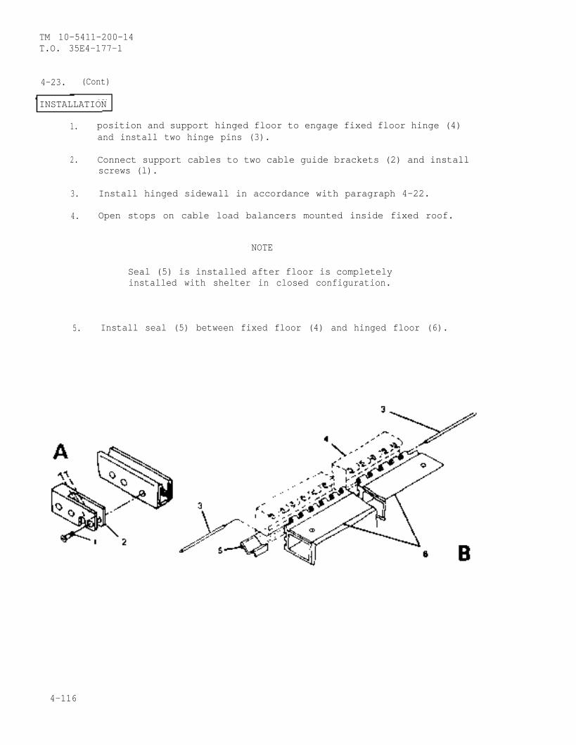
TM 10-5411-200-14T.O. 35E4-177-1
4-23. (Cont)
INSTALLATION
1. position and support hinged floor to engage fixed floor hinge (4)and install two hinge pins (3).
2. Connect support cables to two cable guide brackets (2) and installscrews (l).
3. Install hinged sidewall in accordance with paragraph 4-22.
4. Open stops on cable load balancers mounted inside fixed roof.
NOTE
Seal (5) is installed after floor is completelyinstalled with shelter in closed configuration.
5. Install seal (5) between fixed floor (4) and hinged floor (6).
4-116
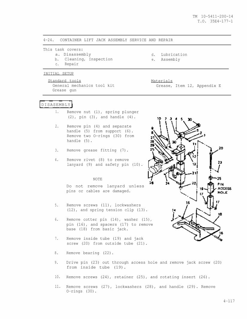
TM 10-5411-200-14T.O. 35E4-177-1
4-24. CONTAINER LIFT JACK ASSEMBLY SERVICE AND REPAIR
This task covers:a. Disassembly d. Lubricationb. Cleaning, Inspection e. Assemblyc. Repair
INITIAL SETUP
Standard tools MaterialsGeneral mechanics tool kit Grease, Item 12, Appendix EGrease gun
DISASEMBLY
1.
2.
3.
4.
5.
6.
7.
8.
9.
Remove nut (l), spring plunger(2), pin (3), and handle (4).
Remove pin (4) and separatehandle (5) from support (6).Remove two O-rings (30) fromhandle (5).
Remove grease fitting (7).
Remove rivet (8) to removelanyard (9) and safety pin (10).
NOTE
Do not remove lanyard unlesspins or cables are damaged.
Remove screws (11), lockwashers(12), and spring tension clip (13).
Remove cotter pin (14), washer (15),pin (16), and spacers (17) to removebase (18) from basic jack.
Remove inside tube (19) and jackscrew (20) from outside tube (21).
Remove bearing (22).
Drive pin (23) out through access hole and remove jack screw (20)from inside tube (19).
10. Remove screws (24), retainer (25), and rotating insert (26).
11. Remove screws (27), lockwashers (28), and handle (29). RemoveO-rings (30).
4-117

TM 10-5411-200-14T.O. 35E4-177-1
4-24. (cont)
CLEANING, INSPECTION
1. Clean jack assembly and component surfaces.
2. Inspect mounting surfaces for corrosion and damage.
3. Inspect for and replace if necessary:
a. Missing or damaged components
b. Corrosion or paint damage.
REPAIR
Corrosion or paint damage. (Refer to)
LUBRICATIONpara. 4-43)
Lubricate jack assembly with grease.
ASSEMBLY
1.
2.
3.
4.
5.
6.
Position handle (29) onrotating insert (26) andinstall lockwashers (28)and screws (27). InstallO-rings (30).
Position rotating insert (26)in outside tube (21) and secureretainer (25) with screws (24).
Install jack screw (20) ininside tube (19).
Align hole in jack screw (20)with access hole in inside tube(19) and install pin (23).
Pack bearing (22) with greaseand place on jack screw (20).
Install inside tube (19) inoutside tube (21).
4-118
TM 10-5411-200-14T.O. 35E4-177-1
4-24. (cont)
7. Position handle (5) in support (6) and on jack screw (19) with holesin handle yoke and jack screw aligned. Install pins (3 and 4).
8. Install spring plunger (2) in handle yoke and secure with nut (l).Adjust nut to control handle movement.
9. Position basic jack on base (18) with spacers (17) and secure withpin (16), washer (15), and new cotter pin (14).
10. Install grease fitting (7) and lubricate jack with grease.
4-25. PERSONNEL DOOR END ENDWALL PANEL REPLACEMENT AND REPAIR
This task covers:a. Removal d. Repairb. Disassembly e. Assemblyc. Cleaning, Inspection f. Installation
INITIAL SETUP
Special Tools MaterialsHand blind riveter, Appendix B, Item 2 Adhesive, Item 2, Appendix E
Personnel - 4 Standard tools1 Electrician General mechanics tool kit
REMOVAL
Personnel Door End Endwall Panel
1. Set main circuit breaker to OFF position.
2. Disconnect service entry power at power entry panel and removecomponents. (Refer to paragraph 5-3)
3. Remove door activated blackout switch and associated wiring. (Referto paragraph 4-15)
4. Remove area light assembly. (Refer to paragraph 3-4)
5. Remove hinged endwalls adjacent to personnel door end panel endwallin accordance with paragraph 4-21.
4-119
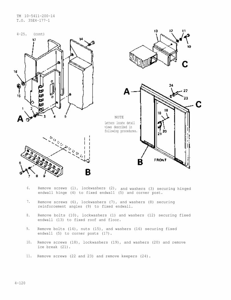
TM 10-5411-200-14T.O. 35E4-177-1
4-25. (cont)
NOTELetters locate detailviews described infollowing procedures.
6.
7.
8.
9.
10.
11.
Remove screws (l), lockwashers (2), and washers (3) securing hingedendwall hinge (4) to fixed endwa11 (5) and corner post.
— . .
Remove screws (6), lockwashers (7), and washers (8) securingreinforcement angles (9) to fixed endwall.
Remove bolts (10), lockwashers (1) and washers (12) securing fixedendwall (13) to fixed roof and floor.
Remove bolts (14), nuts (15), and washers (16) securing fixedendwall (5) to corner posts (17).
Remove screws (18), lockwashers (19), and washers (20) and removeice break (21).
Remove screws (22 and 23) and remove keepers (24).
4-120
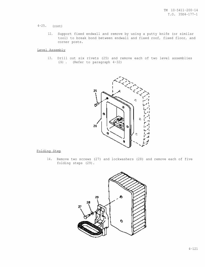
TM 10-5411-200-14T.O. 35E4-177-1
4-25. (cont)
12. Support fixed endwall and remove by using a putty knife (or similartool) to break bond between endwall and fixed roof, fixed floor, andcorner posts.
Level Assembly
13. Drill out six rivets (25) and remove each of two level assemblies(26) . (Refer to paragraph 4-32)
Folding Step
14. Remove two screws (27) and lockwashers (28) and remove each of fivefolding steps (29).
4-121
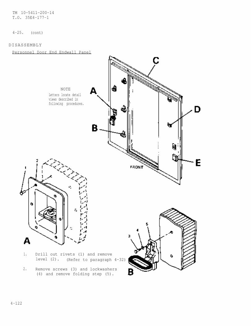
TM 10-5411-200-14T.O. 35E4-177-1
4-25. (cont)
DISASSEMBLY
Personnel Door End Endwall Panel
NOTELetters locate detailviews described infollowing procedures.
1.
2.
Drill out rivets (1) and removelevel (2). (Refer to paragraph 4-32)
Remove screws (3) and lockwashers(4) and remove folding step (5).
4-122
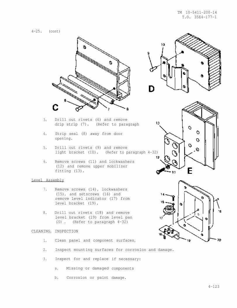
4-25. (cont)
3.
4.
5.
6.
Drill out rivets (6) and removedrip strip (7). (Refer to paragraph
Strip seal (8) away from dooropening.
Drill out rivets (9) and removelight bracket (10). (Refer to paragraph 4-32)
Remove screws (11) and lockwashers(12) and remove upper mobilizerfitting (13).
TM 10-5411-200-14T.O. 35E4-177-1
Level Assembly
7. Remove screws (14), lockwashers(15), and setscrews (16) andremove level indicator (17) fromlevel bracket (19).
8. Drill out rivets (18) and removelevel bracket (19) from level pan(20) . (Refer to paragraph 4-32)
CLEANING, INSPECTION
1. Clean panel and component surfaces,
2. Inspect mounting surfaces for corrosion and damage.
3. Inspect for and replace
a. Missing or damaged
b. Corrosion or paint
if necessary:
components
damage.
4-123
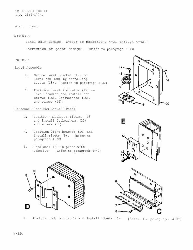
TM 10-5411-200-14T.O. 35E4-177-1
4-25. (cont)
R E P A I R
ASSEMBLY
Level Assembly
Panel skin damage. (Refer to paragraphs 4-31 through 4-42.)
Correction or paint damage. (Refer to paragraph 4-43)
1. Secure level bracket (19) tolevel pan (20) by installingrivets (18). (Refer to paragraph 4-32)
2. Position level indicator (17) onlevel bracket and install set-screws (16), lockwashers (15),and screws (14).
Personnel Door End Endwall Panel
3. Position mobilizer fitting (13)and install lockwashers (12)and screws (11).
4. Position light bracket (10) andinstall rivets (9). (Refer toparagraph 4-32)
5. Bond seal (8) in place withadhesive. (Refer to paragraph 4-40)
6. Position drip strip (7) and install rivets (6). (Refer to paragraph 4-32)
4-124
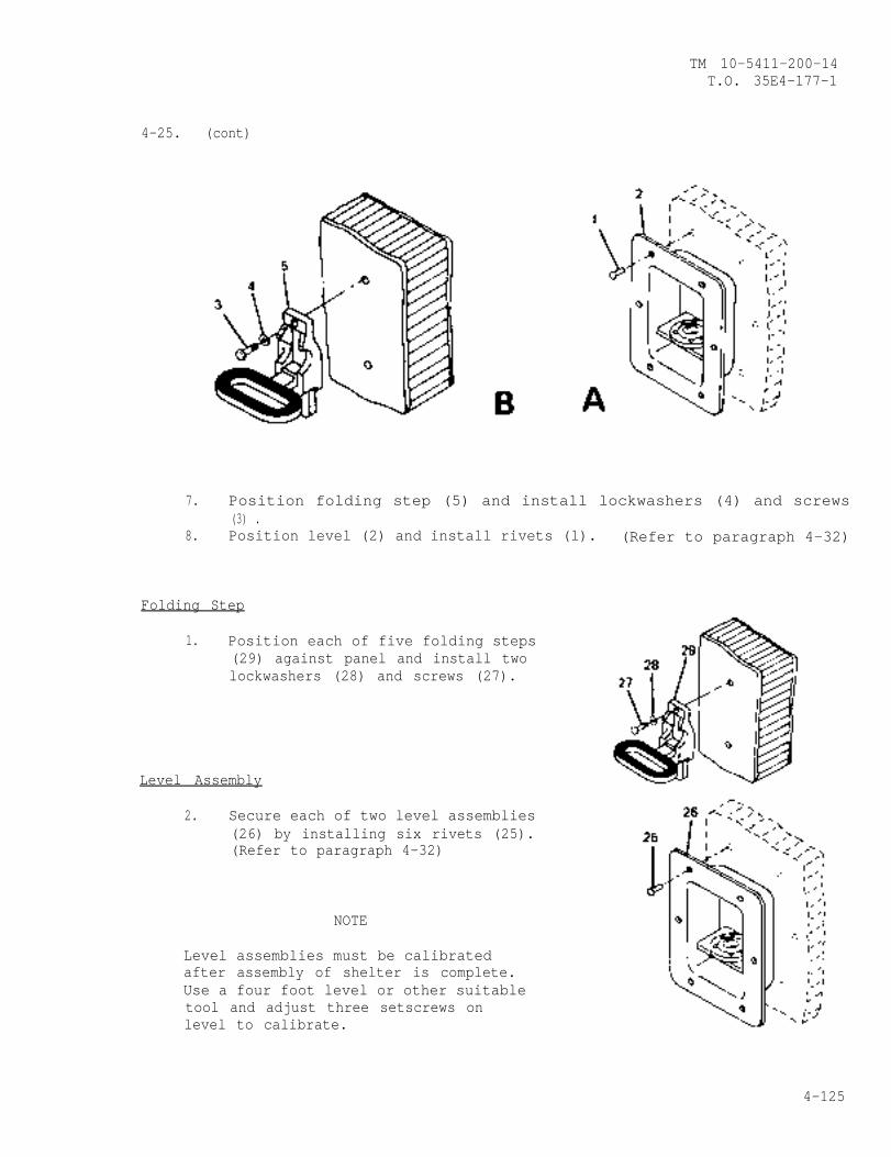
TM 10-5411-200-14T.O. 35E4-177-1
4-25. (cont)
7. Position folding step (5) and install lockwashers (4) and screws(3) .
8. Position level (2) and install rivets (l). (Refer to paragraph 4-32)
Folding Step
1. Position each of five folding steps(29) against panel and install twolockwashers (28) and screws (27).
Level Assembly
2. Secure each of two level assemblies(26) by installing six rivets (25).(Refer to paragraph 4-32)
NOTE
Level assemblies must be calibratedafter assembly of shelter is complete.Use a four foot level or other suitabletool and adjust three setscrews onlevel to calibrate.
4-125
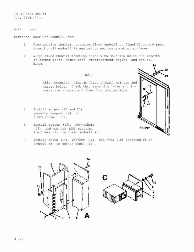
TM 10-5411-200-14T.O. 35E4-177-1
4-25. (cont)
Personnel Door End Endwall Panel
3. From outside shelter, position fixed endwall on fixed floor and pushinward until endwall is against corner posts mating surfaces.
4. Align fixed endwall mounting holes with mounting holes and insertsin corner posts, fixed roof, reinforcement angles, and endwallhinge.
5.
6.
7.
NOTE
Align mounting holes at fixed endwall corners andinsert bolts. Check that remaining holes and in-serts are aligned and free from obstructions.
Install screws (22 and 23)securing keepers (24) tofixed endwall (5).
Install screws (18), lockwashers(19), and washers (20) securingice break (21) to fixed endwall (5).
Install bolts (14), washers (16), and nuts (15) securing fixedendwall (5) to corner posts (17).
4-126
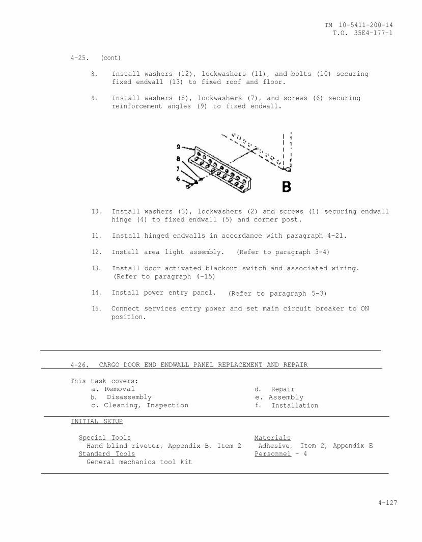
TM 10-5411-200-14T.O. 35E4-177-1
4-25. (cont)
8. Install washers (12), lockwashers (11), and bolts (10) securingfixed endwall (13) to fixed roof and floor.
9. Install washers (8), lockwashers (7), and screws (6) securingreinforcement angles (9) to fixed endwall.
10. Install washers (3), lockwashers (2) and screws (1) securing endwallhinge (4) to fixed endwall (5) and corner post.
11. Install hinged endwalls in accordance with paragraph 4-21.
12. Install area light assembly. (Refer to paragraph 3-4)
13. Install door activated blackout switch and associated wiring.(Refer to paragraph 4-15)
14. Install power entry panel. (Refer to paragraph 5-3)
15. Connect services entry power and set main circuit breaker to ONposition.
4-26. CARGO DOOR END ENDWALL PANEL REPLACEMENT AND REPAIR
This task covers:a. Removal d. Repairb. Disassembly e. Assemblyc. Cleaning, Inspection f. Installation
INITIAL SETUP
Special Tools MaterialsHand blind riveter, Appendix B, Item 2 Adhesive, Item 2, Appendix E
Standard Tools Personnel - 4General mechanics tool kit
4-127

TM 10-5411-200-14T.O. 35E4-177-1
4-26. (cont)
REMOVAL
1.
2.
3.
4.
5.
4-128
NOTELetters locate detailviews described infollowing procedures.
Remove cargo doors in accordance with paragraphs 4-17 and 4-18.
Remove hinged endwalls adjacent fixed cargo endwall in accordancewith paragraph 4-21.
Remove screws (l), lockwashers (2), and washers (3) securing hingedendwall hinge (4) to fixed endwall and corner post.
Remove bolts (5), nuts (6) and washers (7) securing fixed endwall(13) to corner posts (8).
Remove bolts (9), lockwashers (10), and washers (11) securing dripcap (12) and fixed endwall (13) to fixed roof.
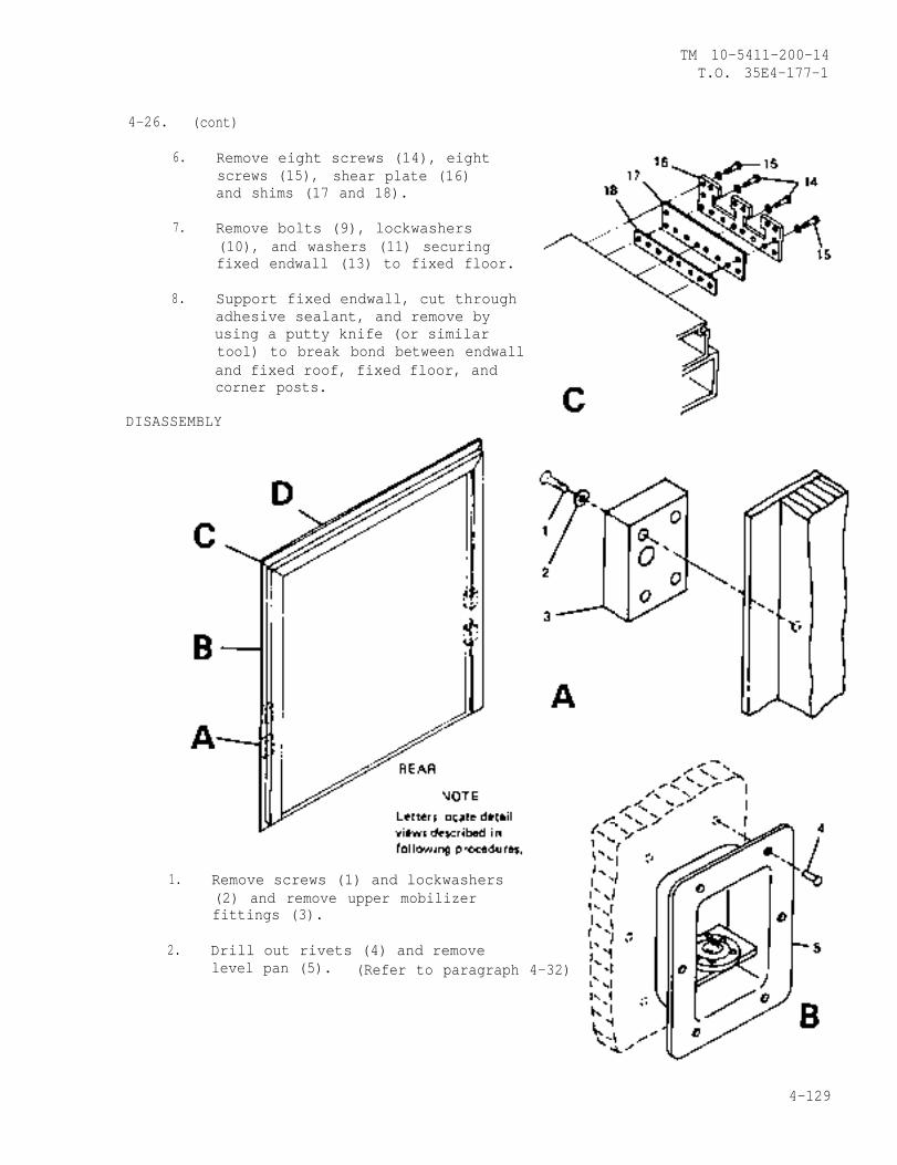
TM 10-5411-200-14T.O. 35E4-177-1
4-26. (cont)
6. Remove eight screws (14), eightscrews (15), shear plate (16)and shims (17 and 18).
7. Remove bolts (9), lockwashers(10), and washers (11) securingfixed endwall (13) to fixed floor.
8. Support fixed endwall, cut throughadhesive sealant, and remove byusing a putty knife (or similartool) to break bond between endwalland fixed roof, fixed floor, andcorner posts.
DISASSEMBLY
1. Remove screws (1) and lockwashers(2) and remove upper mobilizerfittings (3).
2. Drill out rivets (4) and removelevel pan (5). (Refer to paragraph 4-32)
4-129

TM 10-5411-200-14T.O. 35E4-177-1
4-26. (cont)
4. Remove bolts (6), lockwashers (7), drip cap (8), and washers (9).
5. Strip seal (10) away from opening.
CLEANING, INSPECTION
1. Clean panel and component surfaces.
2. Inspect mounting surfaces for corrosion and damage.
3. Inspect for and replace if necessary:
a. Missing or damaged components
b, Corrosion or paint damage.
R E PAIR
1. Panel skin damage. (Refer to paragraphs 4-31 through 4-42.)
2. Corrosion or paint damage. (Refer to paragraph 4-43)
ASSEMBLY
1. When assembling endwall panel to roof, position drip cap (8) andinstall washers (9), lockwashers (7) and bolts (6).
2. position upper mobilizer fitting (3) and install lockwashers (2) andscrews (l).
3. Position level (5) and install rivets (4). (Refer to paragraph 4-32)
4-130
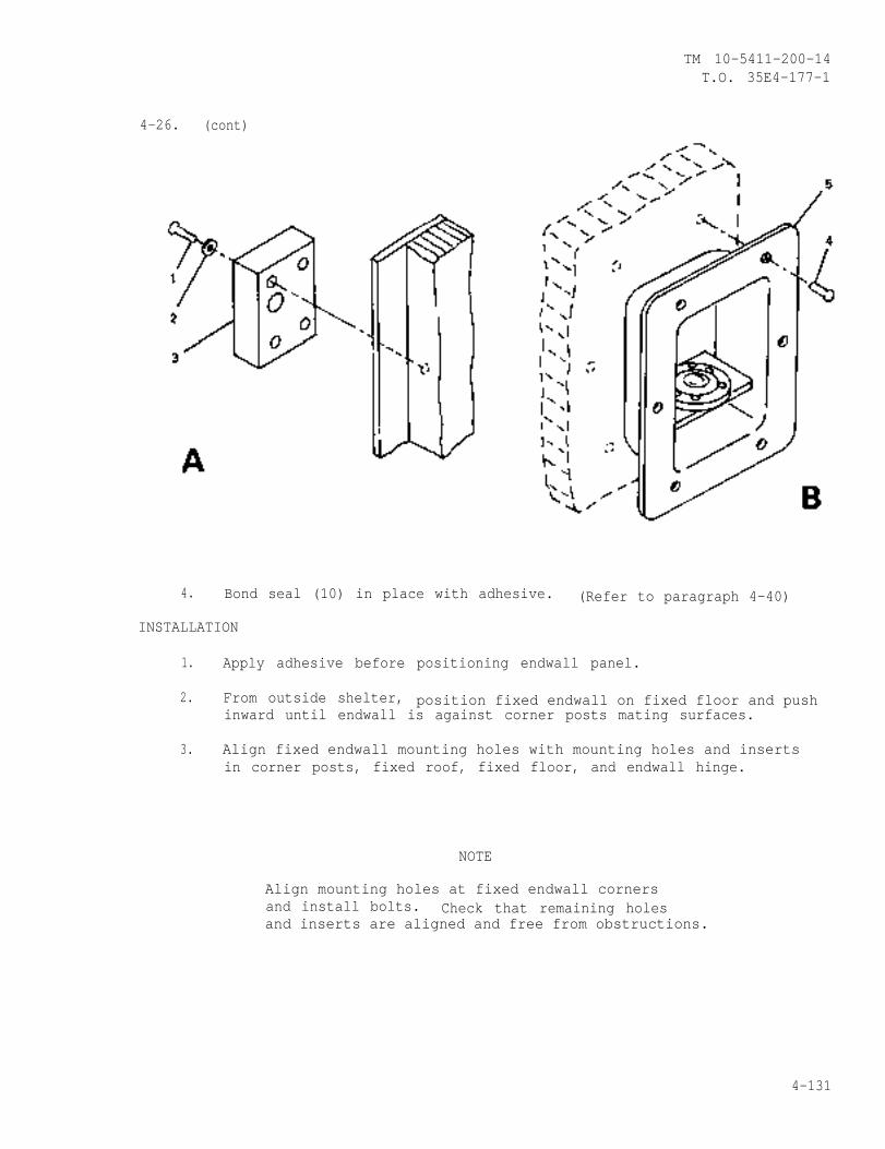
TM 10-5411-200-14T.O. 35E4-177-1
4-26. (cont)
4. Bond seal (10) in place with adhesive. (Refer to paragraph 4-40)
INSTALLATION
1. Apply adhesive before positioning endwall panel.
2. From outside shelter, position fixed endwall on fixed floor and pushinward until endwall is against corner posts mating surfaces.
3. Align fixed endwall mounting holes with mounting holes and insertsin corner posts, fixed roof, fixed floor, and endwall hinge.
NOTE
Align mounting holes at fixed endwall cornersand install bolts. Check that remaining holesand inserts are aligned and free from obstructions.
4-131
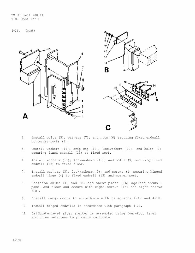
TM 10-5411-200-14T.O. 35E4-177-1
4-26. (cont)
4.
5.
6.
7.
8.
9.
10.
11.
Install bolts (5), washers (7), and nuts (6) securing fixed endwallto corner posts (8).
Install washers (11), drip cap (12), lockwashers (10), and bolts (9)securing fixed endwall (13) to fixed roof.
Install washers (11), lockwashers (10), and bolts (9) securing fixedendwall (13) to fixed floor.
Install washers (3), lockwashers (2), and screws (1) securing hingedendwall hinge (4) to fixed endwall (13) and corner post.
Position shims (17 and 18) and shear plate (16) against endwallpanel and floor and secure with eight screws (15) and eight screws(14) .
Install cargo doors in accordance with paragraphs 4-17 and 4-18.
Install hinged endwalls in accordance with paragraph 4-21.
Calibrate level after shelter is assembled using four-foot leveland three setscrews to properly calibrate.
4-132
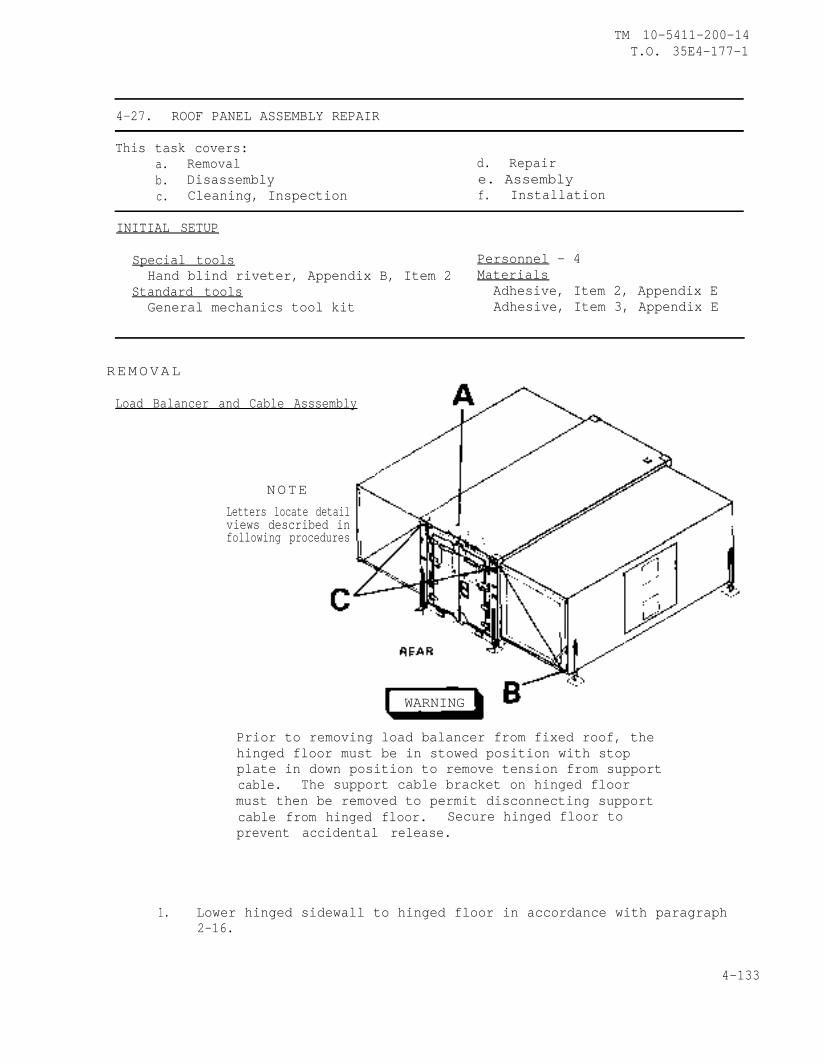
TM 10-5411-200-14T.O. 35E4-177-1
4-27. ROOF PANEL ASSEMBLY REPAIR
This task covers:a. Removal d. Repairb. Disassembly e. Assemblyc. Cleaning, Inspection f. Installation
INITIAL SETUP
Special tools Personnel - 4Hand blind riveter, Appendix B, Item 2 Materials
Standard tools Adhesive, Item 2, Appendix EGeneral mechanics tool kit Adhesive, Item 3, Appendix E
REMOVAL
Load Balancer and Cable Asssembly
NOTELetters locate detailviews described infollowing procedures
WARNING
Prior to removing load balancer from fixed roof, thehinged floor must be in stowed position with stopplate in down position to remove tension from supportcable. The support cable bracket on hinged floormust then be removed to permit disconnecting supportcable from hinged floor. Secure hinged floor toprevent accidental release.
1. Lower hinged sidewall to hinged floor in accordance with paragraph2-16.
4-133
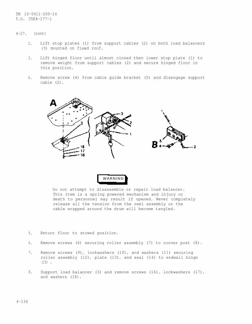
TM 10-5411-200-14T.O. 35E4-177-1
4-27. (cont)
2. Lift stop plates (1) from support cables (2) on both load balancers(3) mounted on fixed roof.
3. Lift hinged floor until almost closed then lower stop plate (1) toremove weight from support cables (2) and secure hinged floor inthis position.
4. Remove screw (4) from cable guide bracket (5) and disengage supportcable (2).
W A R N I N G
Do not attempt to disassemble or repair load balancer.This item is a spring powered mechanism and injury ordeath to personnel may result if opened. Never completelyrelease all the tension from the reel assembly or thecable wrapped around the drum will become tangled.
5. Return floor to stowed position.
6. Remove screws (6) securing roller assembly (7) to corner post (8).
7. Remove screws (9), lockwashers (10), and washers (11) securingroller assembly (12), plate (13), and seal (14) to endwall hinge(15) .
8. Support load balancer (3) and remove screws (16), lockwashers (17),and washers (18).
4-134
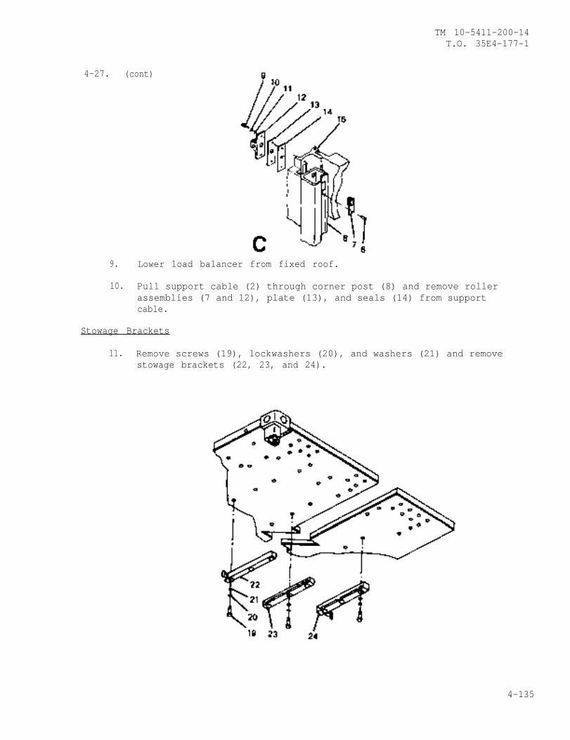
4-27. (cont)
9.
TM 10-5411-200-14T.O. 35E4-177-1
Lower load balancer from fixed roof.
10. Pull support cable (2) through corner post (8) and remove rollerassemblies (7 and 12), plate (13), and seals (14) from supportcable.
Stowage Brackets
11. Remove screws (19), lockwashers (20), and washers (21) and removestowage brackets (22, 23, and 24).
4-135
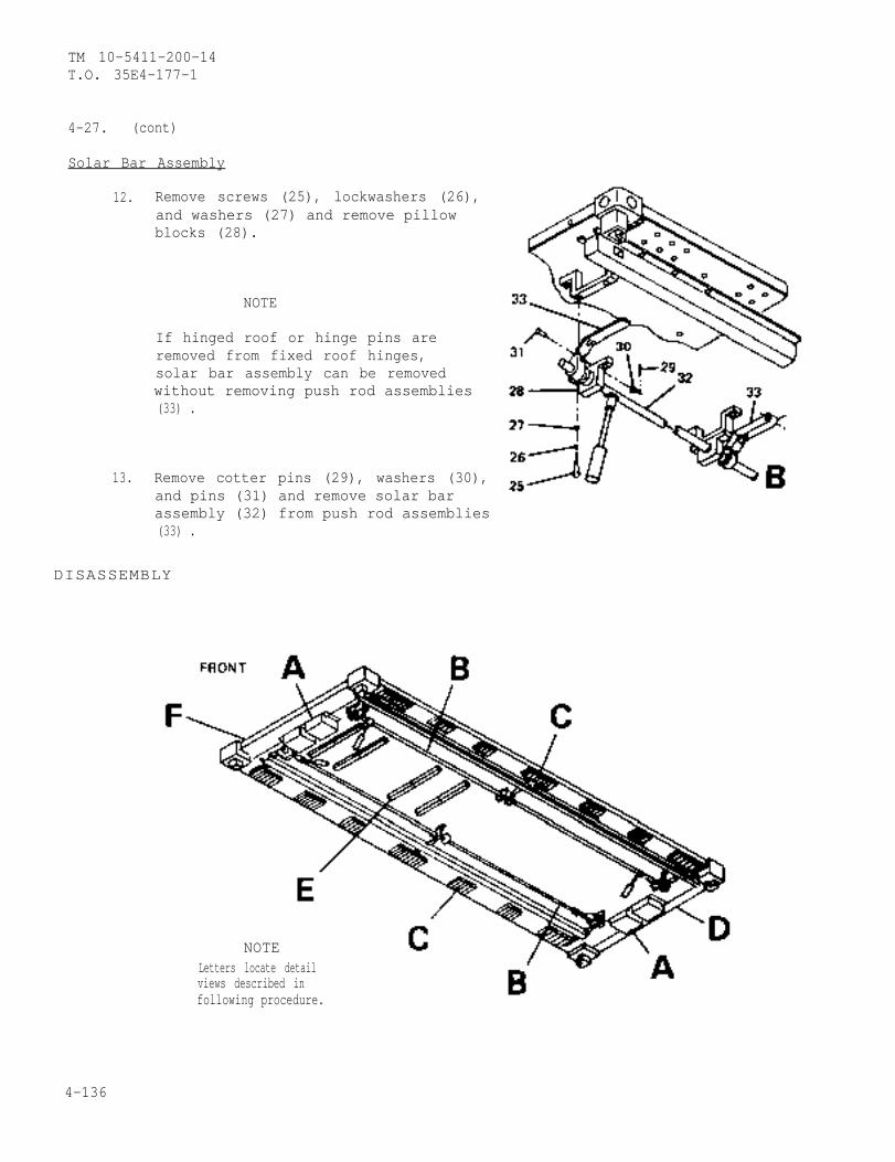
TM 10-5411-200-14T.O. 35E4-177-1
4-27. (cont)
Solar Bar Assembly
12. Remove screws (25), lockwashers (26),and washers (27) and remove pillowblocks (28).
NOTE
If hinged roof or hinge pins areremoved from fixed roof hinges,solar bar assembly can be removedwithout removing push rod assemblies(33) .
13. Remove cotter pins (29), washers (30),and pins (31) and remove solar barassembly (32) from push rod assemblies(33) .
DISASSEMBLY
NOTELetters locate detailviews described infollowing procedure.
4-136
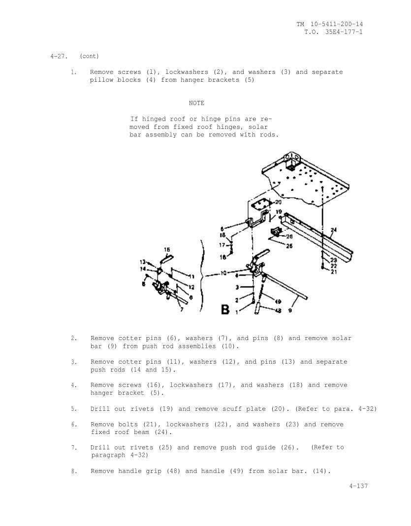
TM 10-5411-200-14T.O. 35E4-177-1
4-27. (cont)
1.
2.
3.
4.
5.
6.
7.
8.
Remove screws (l), lockwashers (2), and washers (3) and separatepillow blocks (4) from hanger brackets (5)
NOTE
If hinged roof or hinge pins are re-moved from fixed roof hinges, solarbar assembly can be removed with rods.
Remove cotter pins (6), washers (7), and pins (8) and remove solarbar (9) from push rod assemblies (10).
Remove cotter pins (11), washers (12), and pins (13) and separatepush rods (14 and 15).
Remove screws (16), lockwashers (17), and washers (18) and removehanger bracket (5).
Drill out rivets (19) and remove scuff plate (20). (Refer to para. 4-32)
Remove bolts (21), lockwashers (22), and washers (23) and removefixed roof beam (24).
Drill out rivets (25) and remove push rod guide (26). (Refer toparagraph 4-32)
Remove handle grip (48) and handle (49) from solar bar. (14).
4-137
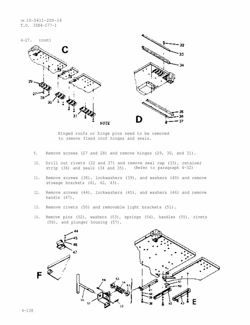
TM 10-5411-200-14T.O. 35E4-177-1
4-27. (cont)
Hinged roofs or hinge pins need to be removedto remove fixed roof hinges and seals.
9. Remove screws (27 and 28) and remove hinges (29, 30, and 31).
10. Drill out rivets (32 and 37) and remove seal cap (33), retainerstrip (36) and seals (34 and 35). (Refer to paragraph 4-32)
11. Remove screws (38), lockwashers (39), and washers (40) and removestowage brackets (41, 42, 43).
12. Remove screws (44), lockwashers (45), and washers (46) and removehandle (47).
13. Remove rivets (50) and removable light brackets (51).
14. Remove pins (52), washers (53), springs (54), handles (55), rivets(56), and plunger housing (57).
4-138
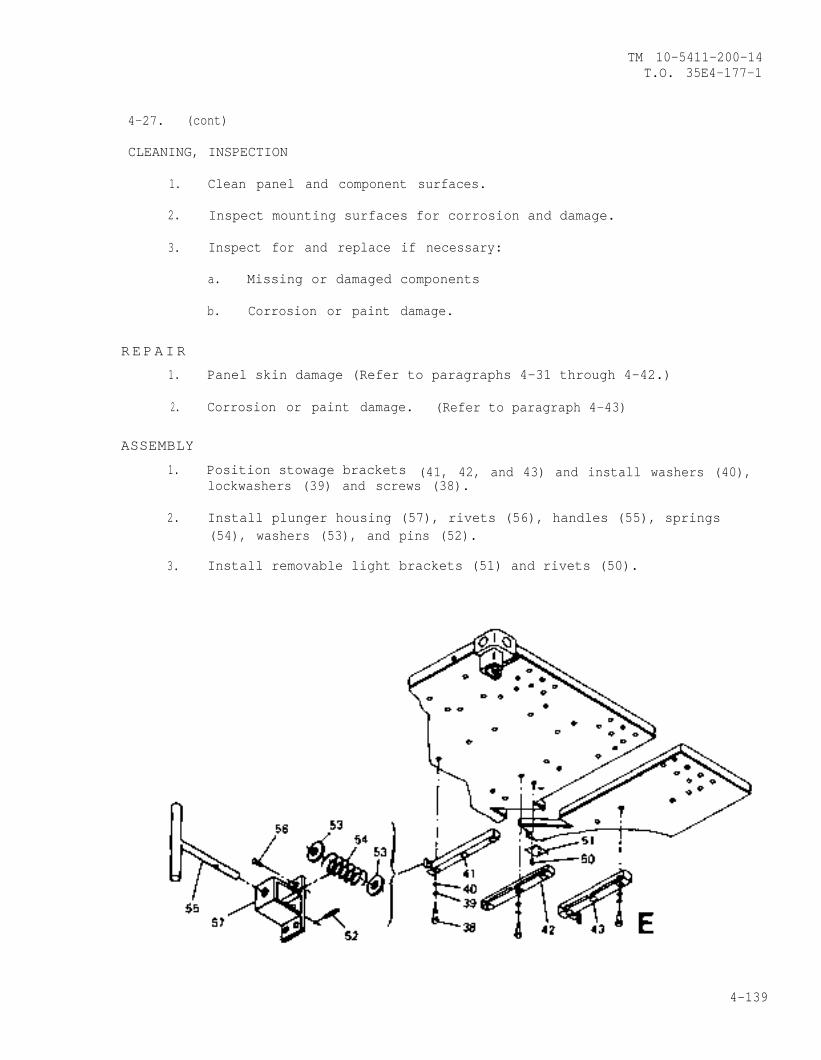
TM 10-5411-200-14T.O. 35E4-177-1
4-27. (cont)
CLEANING, INSPECTION
1. Clean panel and component surfaces.
2. Inspect mounting surfaces for corrosion and damage.
3. Inspect for and replace if necessary:
a. Missing or damaged components
b. Corrosion or paint damage.
R E PAIR
1. Panel skin damage (Refer to paragraphs 4-31 through 4-42.)
Corrosion or paint damage. (Refer to paragraph 4-43)2.
ASSEMBLY
1. Position stowage brackets (41, 42, and 43) and install washers (40),lockwashers (39) and screws (38).
2. Install plunger housing (57), rivets (56), handles (55), springs(54), washers (53), and pins (52).
3. Install removable light brackets (51) and rivets (50).
4-139
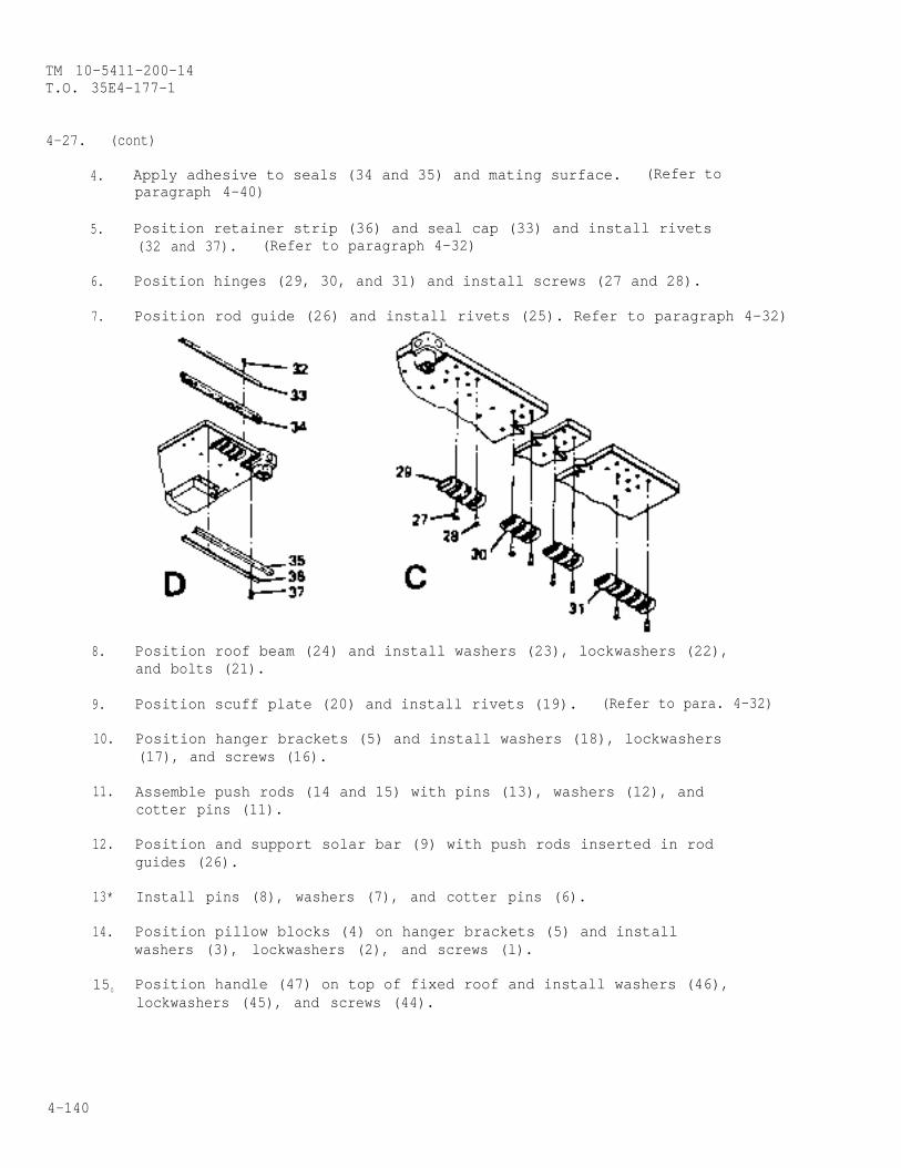
TM 10-5411-200-14T.O. 35E4-177-1
4-27. (cont)
4.
5.
6.
7.
8.
9.
10.
11.
12.
13*
14.
150
Apply adhesive to seals (34 and 35) and mating surface. (Refer toparagraph 4-40)
Position retainer strip (36) and seal cap (33) and install rivets(32 and 37). (Refer to paragraph 4-32)
Position hinges (29, 30, and 31) and install screws (27 and 28).
Position rod guide (26) and install rivets (25). Refer to paragraph 4-32)
Position roof beam (24) and install washers (23), lockwashers (22),and bolts (21).
Position scuff plate (20) and install rivets (19). (Refer to para. 4-32)
Position hanger brackets (5) and install washers (18), lockwashers(17), and screws (16).
Assemble push rods (14 and 15) with pins (13), washers (12), andcotter pins (11).
Position and support solar bar (9) with push rods inserted in rodguides (26).
Install pins (8), washers (7), and cotter pins (6).
Position pillow blocks (4) on hanger brackets (5) and installwashers (3), lockwashers (2), and screws (l).
Position handle (47) on top of fixed roof and install washers (46),lockwashers (45), and screws (44).
4-140
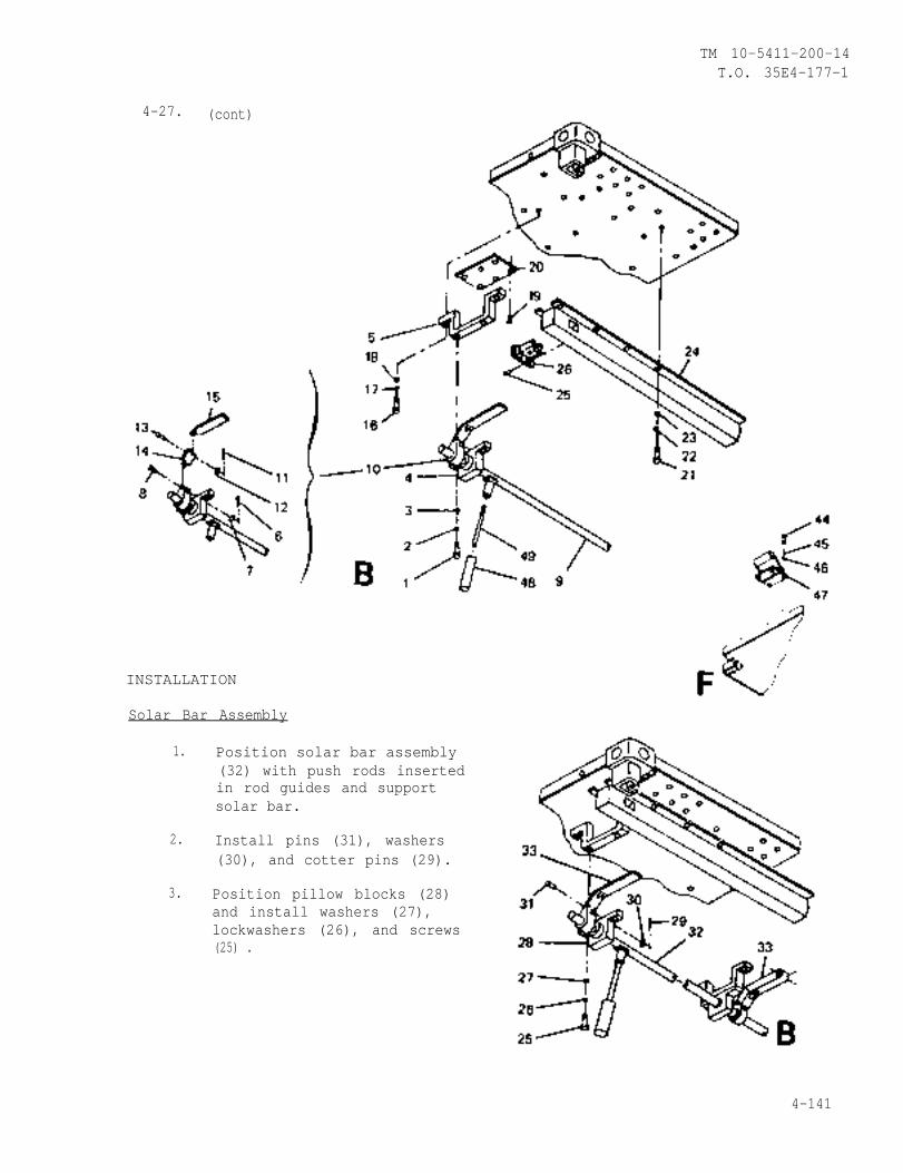
TM 10-5411-200-14T.O. 35E4-177-1
4-27. (cont)
INSTALLATION
Solar Bar Assembly
1. Position solar bar assembly(32) with push rods insertedin rod guides and supportsolar bar.
2. Install pins (31), washers(30), and cotter pins (29).
3. Position pillow blocks (28)and install washers (27),lockwashers (26), and screws(25) .
4-141
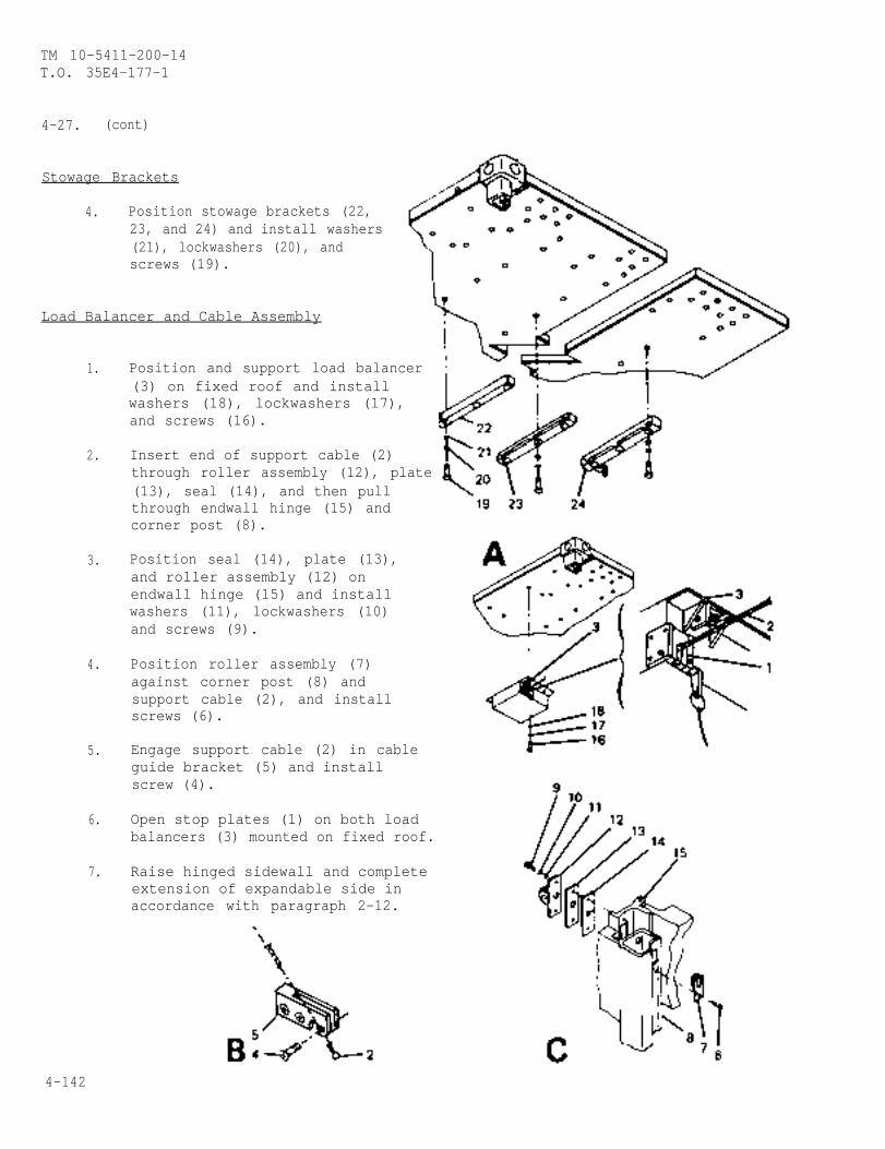
TM 10-5411-200-14T.O. 35E4-177-1
4-27. (cont)
Stowage Brackets
4. Position stowage brackets (22, 23, and 24) and install washers(21), lockwashers (20), andscrews (19).
Load Balancer and Cable Assembly
1. Position and support load balancer (3) on fixed roof and installwashers (18), lockwashers (17),and screws (16).
2. Insert end of support cable (2)through roller assembly (12), plate(13), seal (14), and then pull
3.
4.
5.
6.
7.
through endwall hinge (15) andcorner post (8).
Position seal (14), plate (13),and roller assembly (12) onendwall hinge (15) and installwashers (11), lockwashers (10)and screws (9).
Position roller assembly (7)against corner post (8) andsupport cable (2), and installscrews (6).
Engage support cable (2) in cableguide bracket (5) and installscrew (4).
Open stop plates (1) on both loadbalancers (3) mounted on fixed roof.
Raise hinged sidewall and completeextension of expandable side inaccordance with paragraph 2-12.
4-142
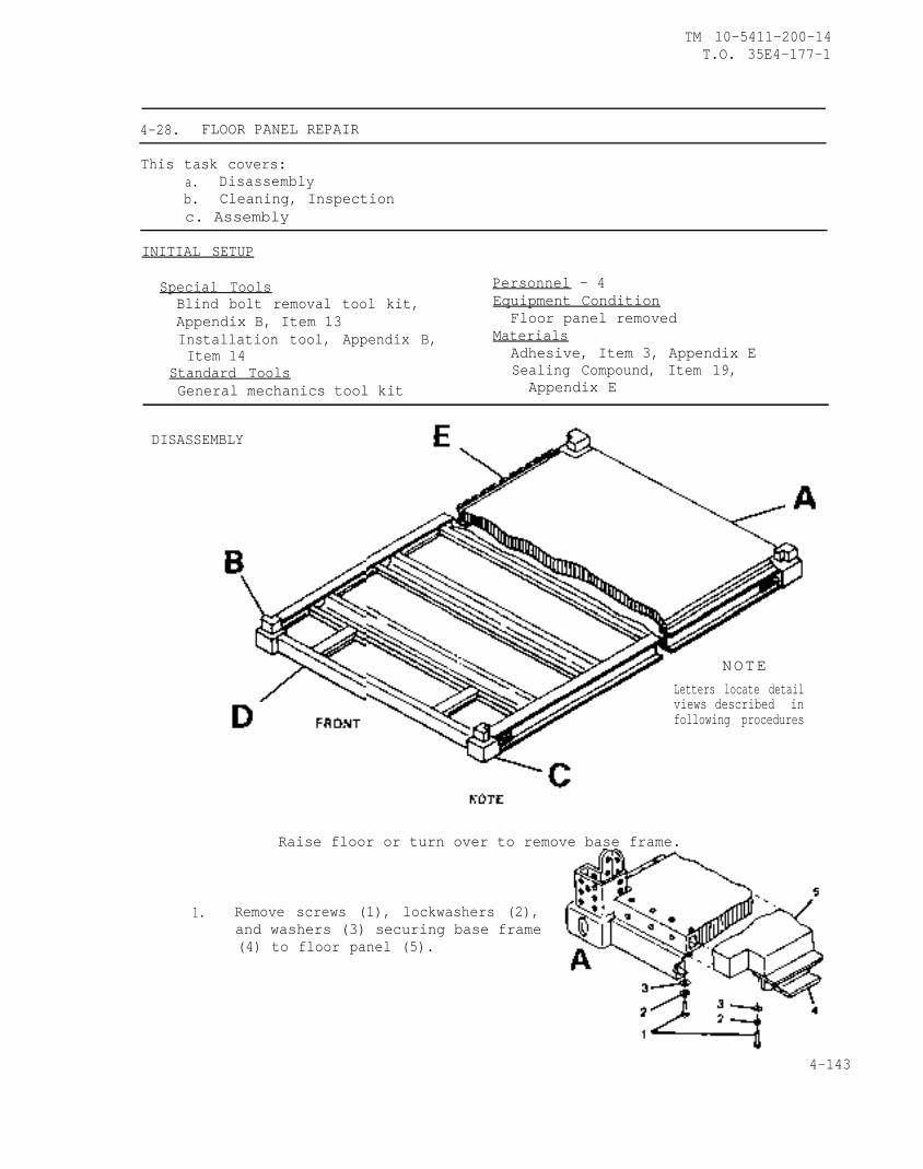
TM 10-5411-200-14T.O. 35E4-177-1
4-28. FLOOR PANEL REPAIR
This task covers:a. Disassemblyb. Cleaning, Inspectionc. Assembly
INITIAL SETUP
Special Tools Personnel - 4Blind bolt removal tool kit, Equipment ConditionAppendix B, Item 13 Floor panel removedInstallation tool, Appendix B, MaterialsItem 14 Adhesive, Item 3, Appendix E
Standard Tools Sealing Compound, Item 19,General mechanics tool kit Appendix E
DISASSEMBLY
NOTELetters locate detailviews described infollowing procedures
1.
Raise floor or turn over to remove base frame.
Remove screws (1), lockwashers (2),and washers (3) securing base frame(4) to floor panel (5).
4-143
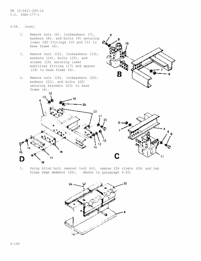
TM 10-5411-200-14T.O. 35E4-177-1
4-28. (cont)
2. Remove nuts (6), lockwashers (7),washers (8), and bolts (9) securing
3.
4.
lower ISO fittings (10 and 11) to base frame (4).
Remove nuts (12), lockwashers (13),washers (14), bolts (15), andscrews (16) securing lowermobilizer fitting (17) and spacer(18) to base frame (4).
Remove nuts (19), lockwashers (20),washers (21), and bolts (22)securing brackets (23) to baseframe (4).
5. Using blind bolt removal tool kit, remove 224 rivets (24) and twohinge edge members (25). (Refer to paragraph 4-32)
4-144
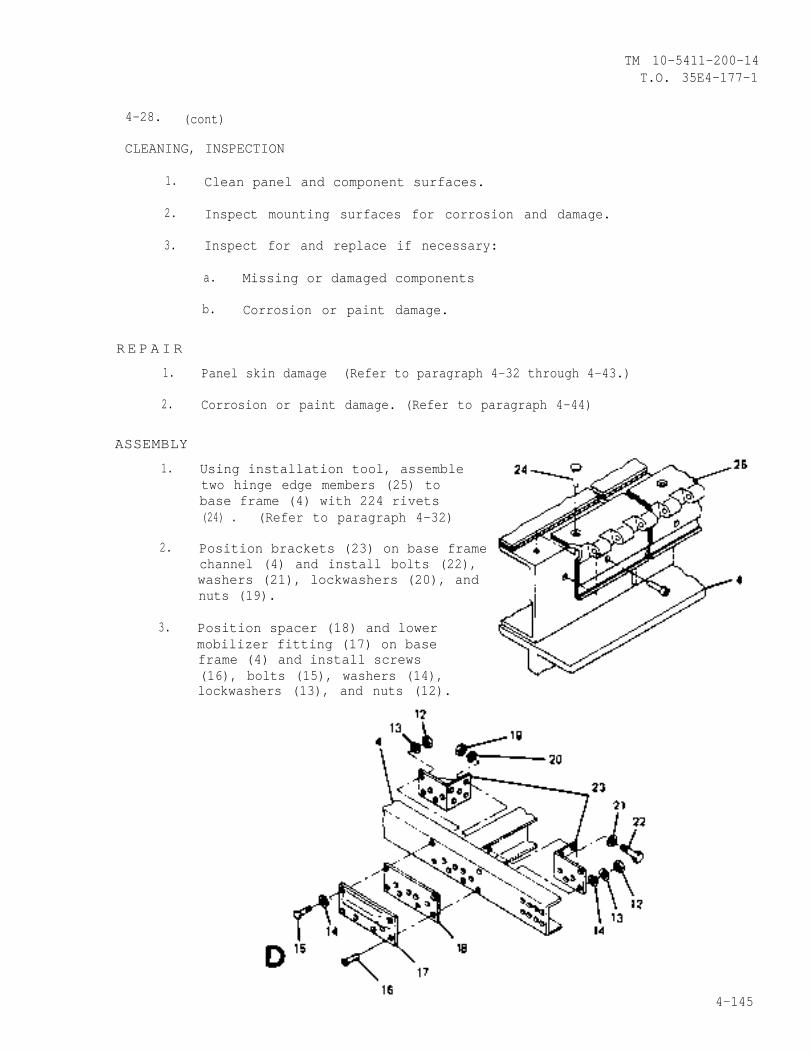
TM 10-5411-200-14T.O. 35E4-177-1
4-28. (cont)
CLEANING, INSPECTION
1.
2.
3.
R E P A I R
1.
2.
ASSEMBLY
1.
2.
3.
Clean panel and component surfaces.
Inspect mounting surfaces for corrosion and damage.
Inspect for and replace if necessary:
a. Missing or damaged components
b. Corrosion or paint damage.
Panel skin damage (Refer to paragraph 4-32 through 4-43.)
Corrosion or paint damage. (Refer to paragraph 4-44)
Using installation tool, assembletwo hinge edge members (25) tobase frame (4) with 224 rivets(24) . (Refer to paragraph 4-32)
Position brackets (23) on base framechannel (4) and install bolts (22),washers (21), lockwashers (20), andnuts (19).
Position spacer (18) and lowermobilizer fitting (17) on baseframe (4) and install screws(16), bolts (15), washers (14),lockwashers (13), and nuts (12).
4-145
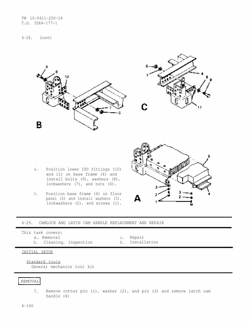
TM 10-5411-200-14T.O. 35E4-177-1
4-28. (cont)
4.
5.
Position lower ISO fittings (10)and 11) on base frame (4) andinstall bolts (9), washers (8),lockwashers (7), and nuts (6).
Position base frame (4) on floorpanel (5) and install washers (3),lockwashers (2), and screws (1).
4-29. CAMLOCK AND LATCH CAM HANDLE REPLACEMENT AND REPAIR
This task covers:a. Removal c. Repairb. Cleaning, Inspection d. Installation
INITIAL SETUP
Standard toolsGeneral mechanics tool kit
REMOVAL
.1.
4-146
Remove cotter pin (l), washer (2), and pin (3) and remove latch camhandle (4)
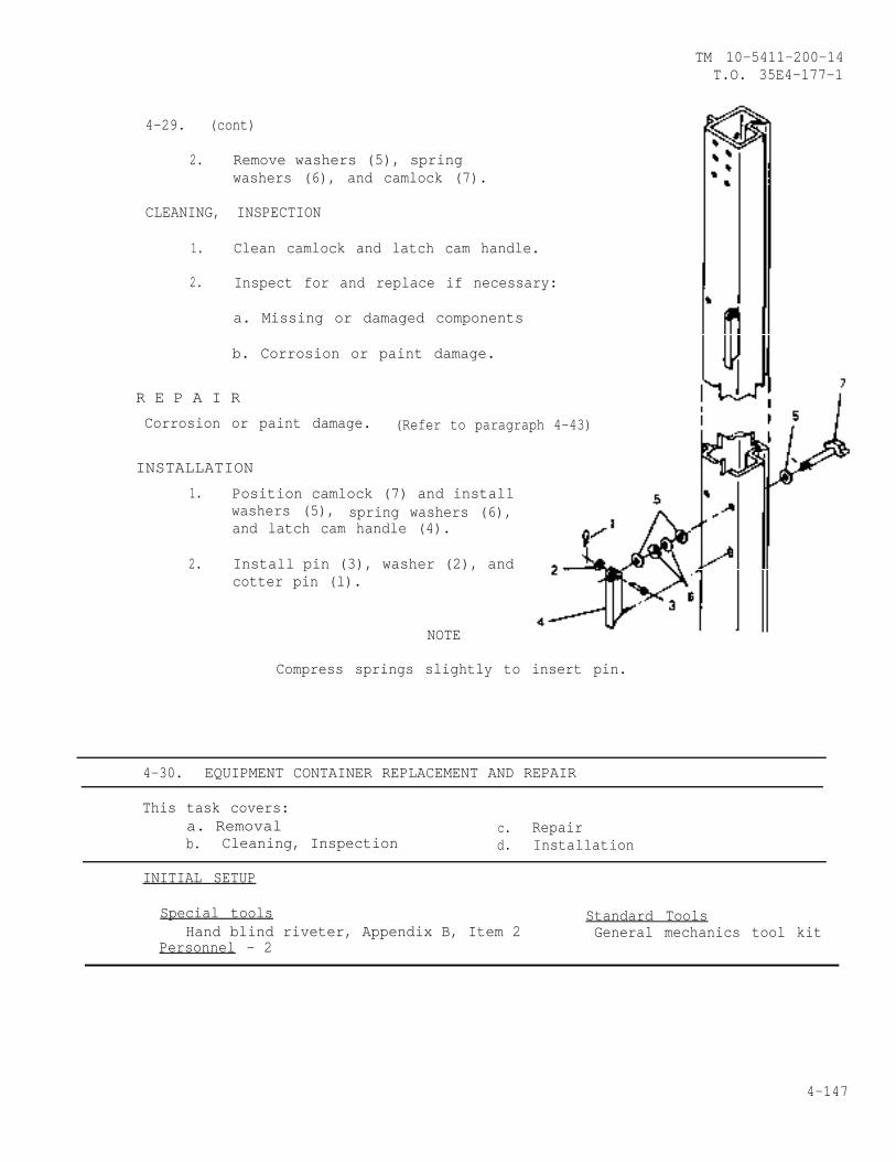
TM 10-5411-200-14T.O. 35E4-177-1
4-29. (cont)
2. Remove washers (5), springwashers (6), and camlock (7).
CLEANING, INSPECTION
1. Clean camlock and latch cam handle.
2. Inspect for and replace if necessary:
a. Missing or damaged components
b. Corrosion or paint damage.
R E P A I R
Corrosion or paint damage. (Refer to paragraph 4-43)
INSTALLATION
1. Position camlock (7) and installwashers (5), spring washers (6),and latch cam handle (4).
2. Install pin (3), washer (2), andcotter pin (l).
NOTE
Compress springs slightly to insert pin.
4-30. EQUIPMENT CONTAINER REPLACEMENT AND REPAIR
This task covers:a. Removal c. Repairb. Cleaning, Inspection d. Installation
INITIAL SETUP
Special tools Standard ToolsHand blind riveter, Appendix B, Item 2 General mechanics tool kit
Personnel - 2
4-147
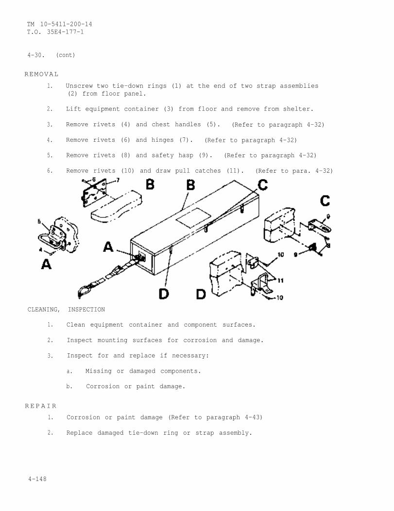
TM 10-5411-200-14T.O. 35E4-177-1
4-30. (cont)
REMOVAL
1. Unscrew two tie-down rings (1) at the end of two strap assemblies(2) from floor panel.
2. Lift equipment container (3) from floor and remove from shelter.
3. Remove rivets (4) and chest handles (5). (Refer to paragraph 4-32)
4. Remove rivets (6) and hinges (7). (Refer to paragraph 4-32)
5. Remove rivets (8) and safety hasp (9). (Refer to paragraph 4-32)
6. Remove rivets (10) and draw pull catches (11). (Refer to para. 4-32)
CLEANING, INSPECTION
1. Clean equipment container and component surfaces.
2. Inspect mounting surfaces for corrosion and damage.
3. Inspect for and replace if necessary:
a. Missing or damaged components.
b. Corrosion or paint damage.
R E PAIR
1. Corrosion or paint damage (Refer to paragraph 4-43)
2. Replace damaged tie-down ring or strap assembly.
4-148
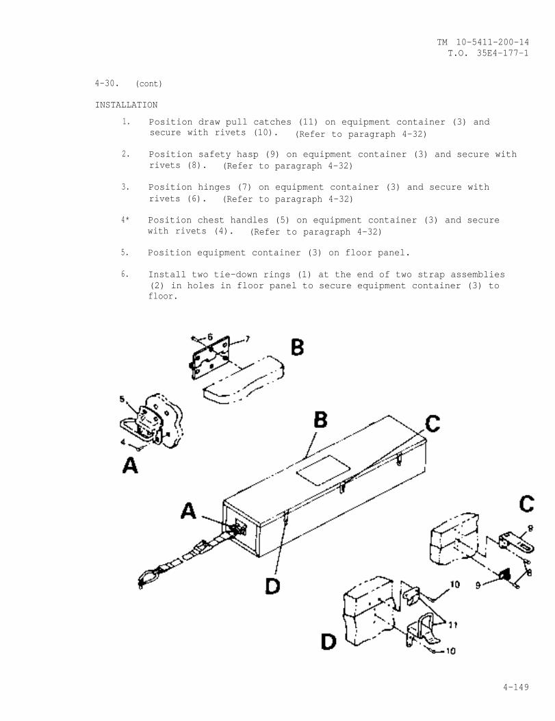
TM 10-5411-200-14T.O. 35E4-177-1
4-30. (cont)
INSTALLATION
1.
2.
3.
4*
5.
6.
Position draw pull catches (11) on equipment container (3) andsecure with rivets (10). (Refer to paragraph 4-32)
Position safety hasp (9) on equipment container (3) and secure withrivets (8). (Refer to paragraph 4-32)
Position hinges (7) on equipment container (3) and secure withrivets (6). (Refer to paragraph 4-32)
Position chest handles (5) on equipment container (3) and securewith rivets (4). (Refer to paragraph 4-32)
Position equipment container (3) on floor panel.
Install two tie-down rings (1) at the end of two strap assemblies(2) in holes in floor panel to secure equipment container (3) tofloor.
4-149
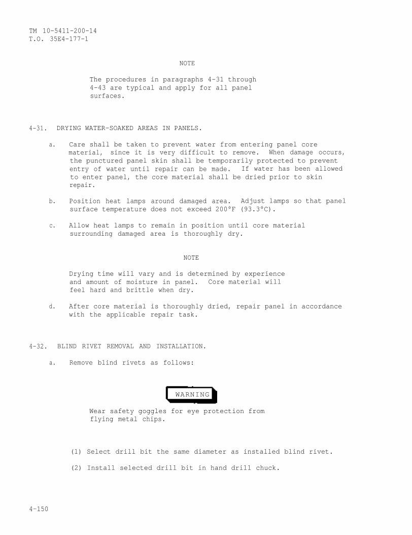
TM 10-5411-200-14T.O. 35E4-177-1
NOTE
The procedures in paragraphs 4-31 through4-43 are typical and apply for all panelsurfaces.
4-31. DRYING WATER-SOAKED AREAS IN PANELS.
a. Care shall be taken to prevent water from entering panel corematerial, since it is very difficult to remove. When damage occurs,the punctured panel skin shall be temporarily protected to prevententry of water until repair can be made. If water has been allowedto enter panel, the core material shall be dried prior to skinrepair.
b. Position heat lamps around damaged area. Adjust lamps so that panelsurface temperature does not exceed 200°F (93.3°C).
c. Allow heat lamps to remain in position until core materialsurrounding damaged area is thoroughly dry.
NOTE
Drying time will vary and is determined by experienceand amount of moisture in panel. Core material willfeel hard and brittle when dry.
d. After core material is thoroughly dried, repair panel in accordancewith the applicable repair task.
4-32. BLIND RIVET REMOVAL AND INSTALLATION.
a. Remove blind rivets as follows:
WARNING
Wear safety goggles for eye protection fromflying metal chips.
(1) Select drill bit the same diameter as installed blind rivet.
(2) Install selected drill bit in hand drill chuck.
4-150

TM 10-5411-200-14T.O. 35E4-177-1
4-32. (cont)
(3) Hold drill perpendicular to the surface toprevent enlargement or damage to existing hole.
(4) Drill through center of rivet just deepenough to sever rivet head from shank.
(5) Remove remainder of rivet with a pinpunch.
(6) Deburr rivet hole.
b. Install blind rivets as follows:
(1) Select proper diameter and length of blindrivet (Items 13-16, Appendix E).
(2) Select appropriate nose piece for handblind riveter and install nose piece.
(3) Wet rivet with sealant (Item 18, AppendixE and insert rivet in hole.
(4) Holding hand blind riveter at right angleto work, install on blind rivet stem.
(5) Push against work with just enoughforce to firmly seat rivet and prevent part separation.
(6) Actuate and pull rivet until stem breaks.
(7) Trim broken stem flush with rivet head.
(8) Firmly press on installed rivet to checktightness of installation.
(9) Remove and replace in accordance withprocedure if installation is unacceptable.
c. Blind bolt removal.
(1) The blind bolt (BP-T & B100-T) canbe removed by using the proper size blind bolt removaltool kit and any portable electric drill with a ratedspeed of no more than 1250 RPM.
(2) The tools in this kit are illustratedon page 4-183, and are tabulated on page 4-184.
(3) The fastener removal consists of four operations:
(a) Operation I - Drill pin. (See page 4-186)
4-151
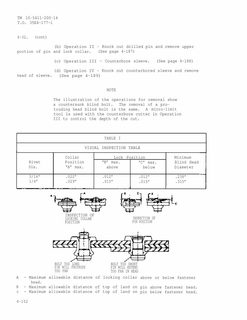
TM 10-5411-200-14T.O. 35E4-177-1
4-32. (cont)
(b) Operation II - Knock out drilled pin and remove upperportion of pin and lock collar. (See page 4-187)
(c) Operation III - Counterbore sleeve. (See page 4-188)
(d) Operation IV - Knock out counterbored sleeve and removehead of sleeve. (See page 4-189)
NOTE
The illustration of the operations for removal showa countersunk blind bolt. The removal of a pro-truding head blind bolt is the same. A micro-limittool is used with the counterbore cutter in OperationIII to control the depth of the cut.
TABLE I
VISUAL INSPECTION TABLE
Collar Lock Position MinimumRivet Position “B” max. “C” max. Blind HeadDia. “A” max. above below Diameter
3/16” .022” .012” .012” .238”1/4” .029” .015” .015” .315”
INSPECTION OFLOCKING COLLAR INSPECTION OFPOSITION PIN POSITION
BOLT TOO LONG BOLT TOO SHORTPIN WILL PROTRUDE PIN WILL EXTENDTOO FAR TOO FAR IN HEAD
A - Maximum allowable distance of locking collarhead.
B - Maximum allowable distance of top of land onc - Maximum allowable distance of top of land on
4-152
above or below fastener
pin above fastener head.pin below fastener head.
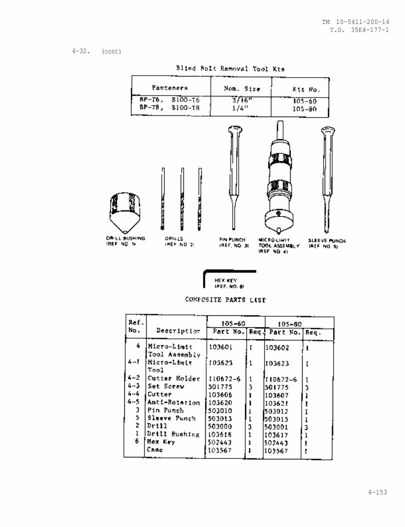
4-32.
TM 10-5411-200-14T.O. 35E4-177-1
(cont)
4-153
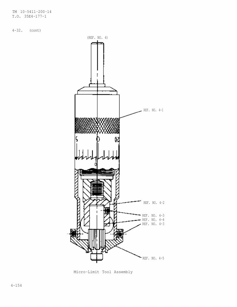
TM 10-5411-200-14T.O. 35E4-177-1
4-32. (cont)
(REF. NO. 4)
REF. NO. 4-1
REF. NO. 4-2
REF. NO. 4-3REF. NO. 4-4REF. NO. 4-3
REF. NO. 4-5
Micro-Limit Tool Assembly
4-154
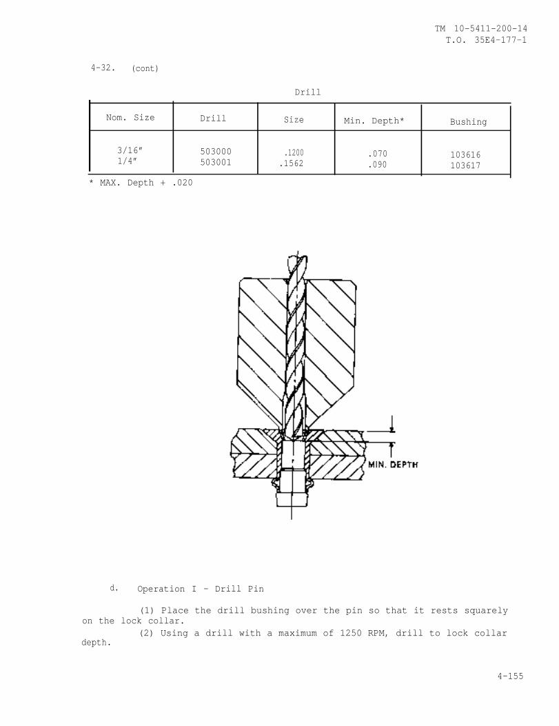
TM 10-5411-200-14T.O. 35E4-177-1
4-32. (cont)
Drill
Nom. Size Drill Size Min. Depth* Bushing
3/16” 503000 .1200 .070 1036161/4” 503001 .1562 .090 103617
* MAX. Depth + .020
d. Operation I - Drill Pin
(1) Place the drill bushing over the pin so that it rests squarelyon the lock collar.
(2) Using a drill with a maximum of 1250 RPM, drill to lock collardepth.
4-155
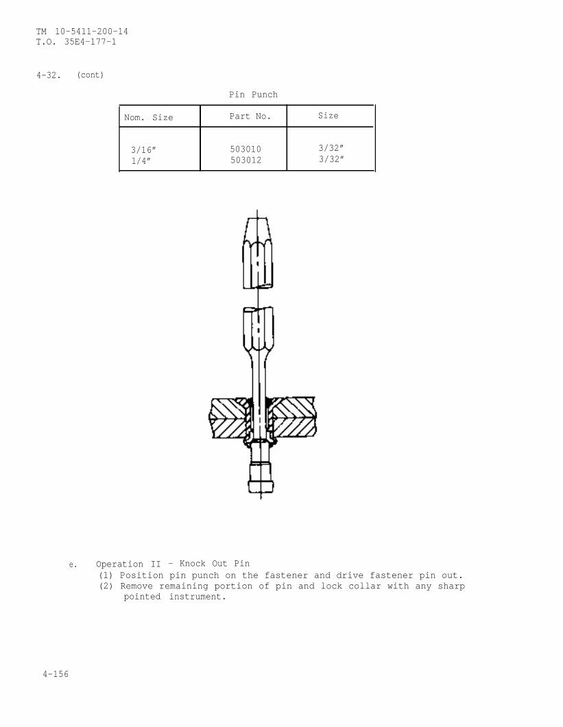
TM 10-5411-200-14T.O. 35E4-177-1
4-32. (cont)
Pin Punch
Nom. Size Part No. Size
3/16” 503010 3/32”1/4” 503012 3/32”
e. Operation II - Knock Out Pin(1) Position pin punch on the fastener and drive fastener pin out.(2) Remove remaining portion of pin and lock collar with any sharp
pointed instrument.
4-156
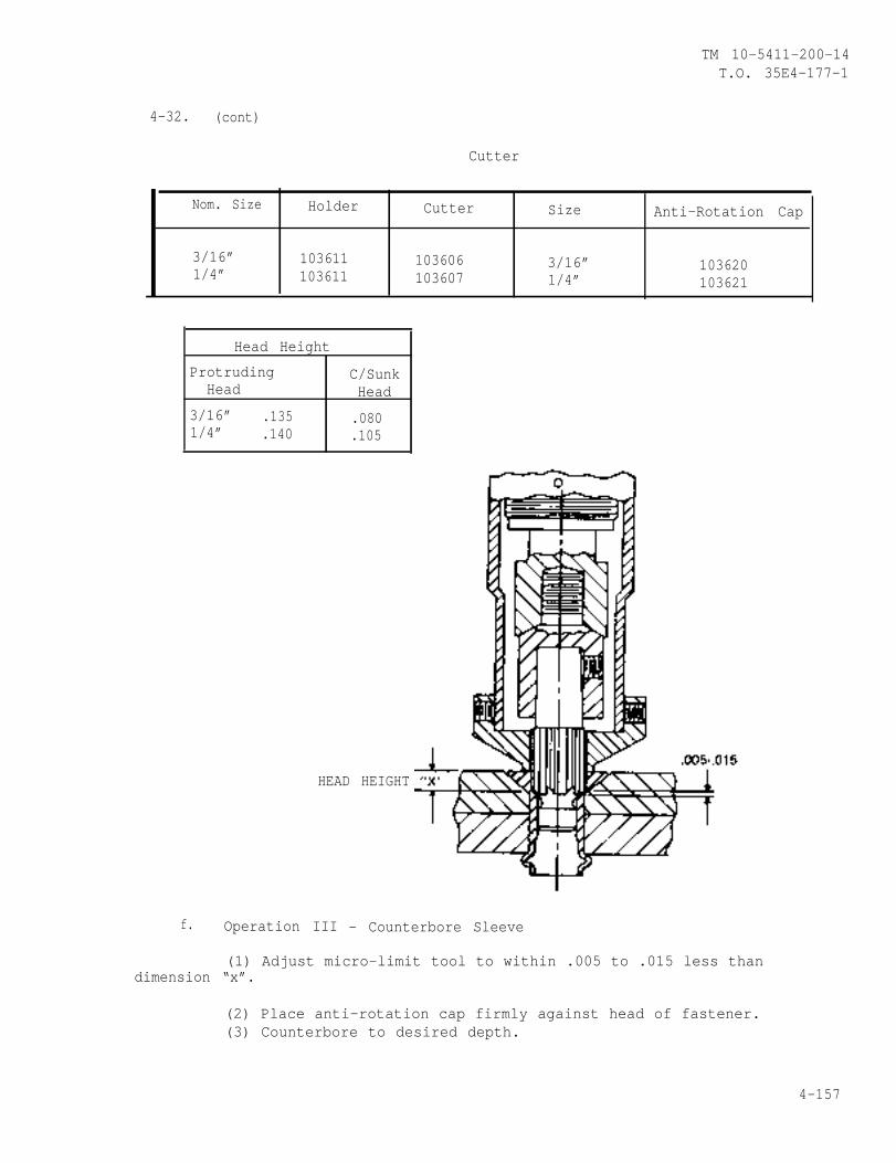
TM 10-5411-200-14T.O. 35E4-177-1
4-32. (cont)
Cutter
Nom. Size Holder Cutter Size Anti-Rotation Cap
3/16” 103611 103606 3/16” 1036201/4” 103611 103607 1/4” 103621
Head Height
Protruding C/SunkHead Head
3/16” .135 .0801/4” .140 .105
HEAD HEIGHT
f. Operation III - Counterbore Sleeve
(1) Adjust micro-limit tool to within .005 to .015 less thandimension “x”.
(2) Place anti-rotation cap firmly against head of fastener.(3) Counterbore to desired depth.
4-157
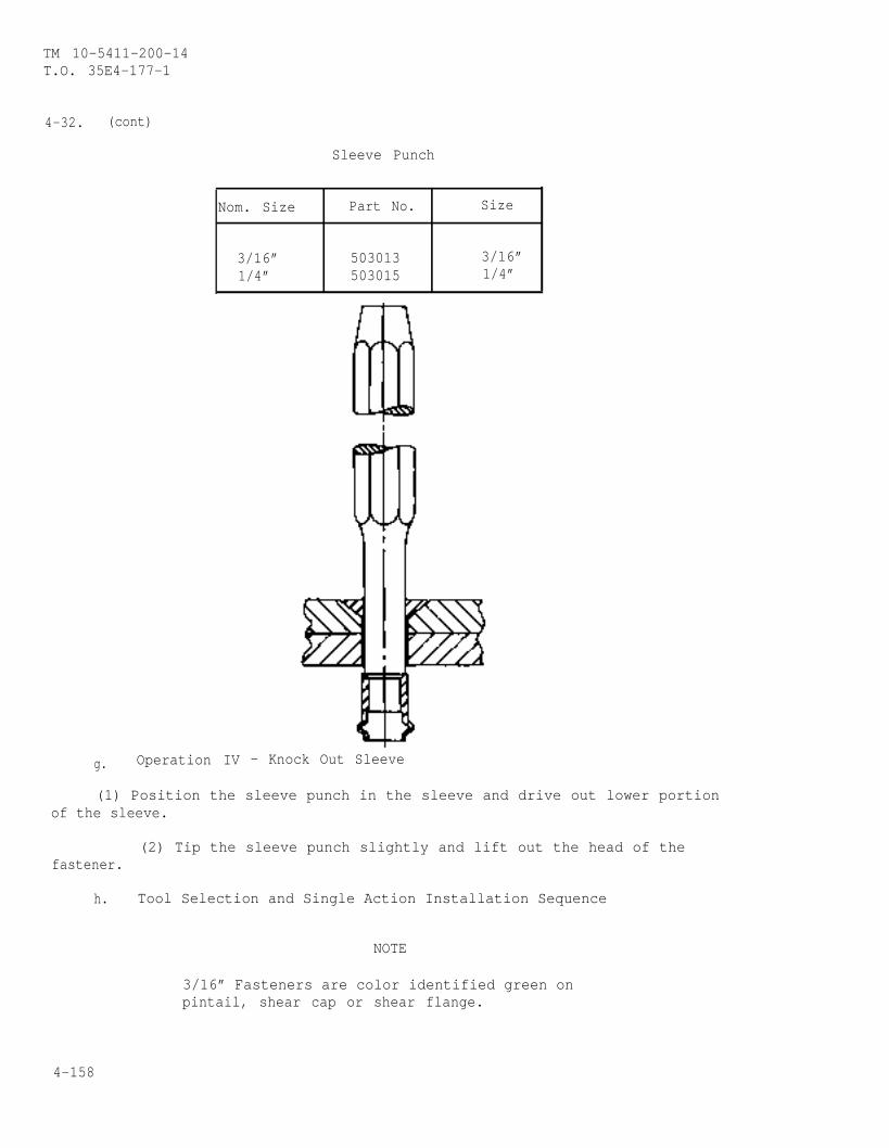
TM 10-5411-200-14T.O. 35E4-177-1
4-32. (cont)
Sleeve Punch
Nom. Size Part No. Size
3/16” 503013 3/16”1/4” 503015 1/4”
g. Operation IV - Knock Out Sleeve
(1) Position the sleeve punch in the sleeve and drive out lower portionof the sleeve.
(2) Tip the sleeve punch slightly and lift out the head of thefastener.
h. Tool Selection and Single Action Installation Sequence
NOTE
3/16” Fasteners are color identified green onpintail, shear cap or shear flange.
4-158
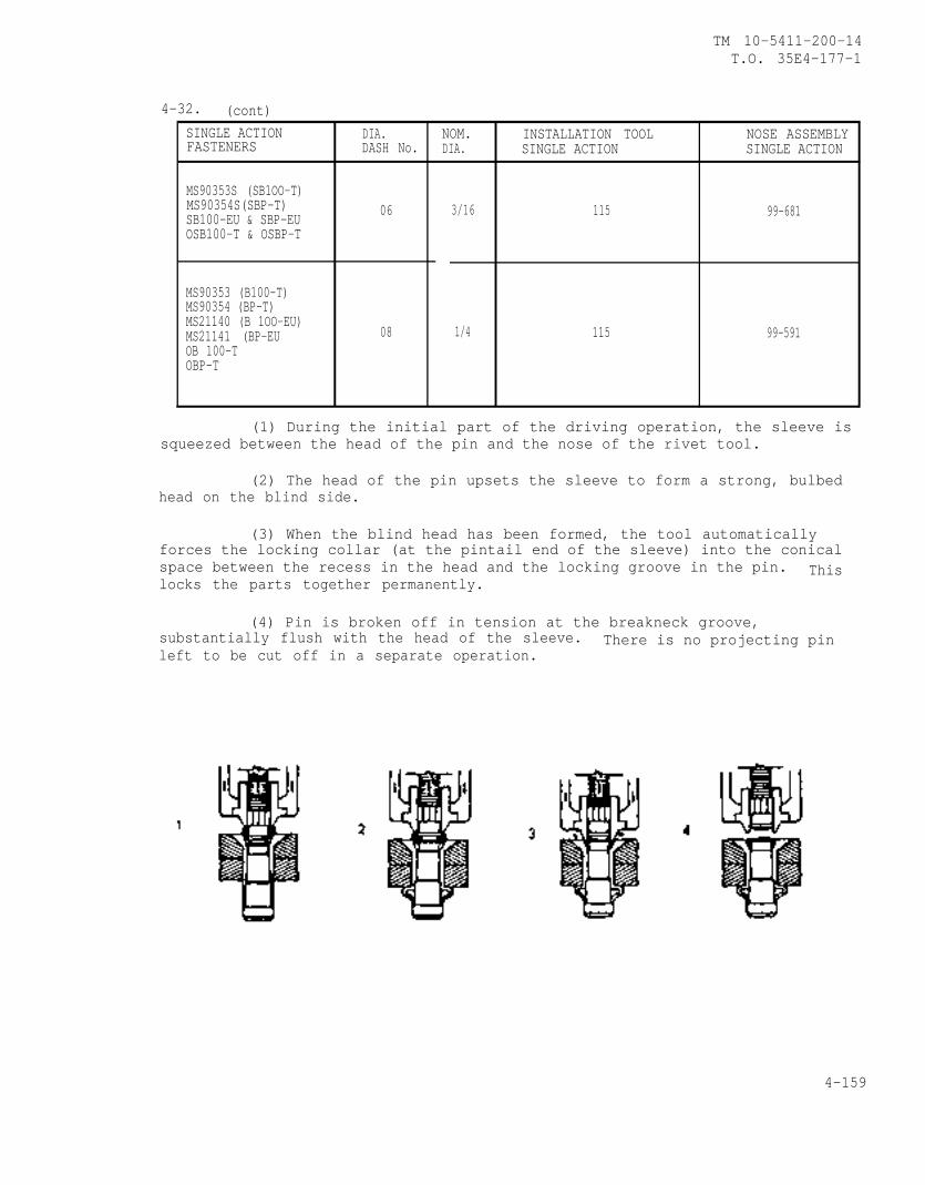
TM 10-5411-200-14T.O. 35E4-177-1
4-32. (cont)SINGLE ACTION DIA. NOM. INSTALLATION TOOL NOSE ASSEMBLYFASTENERS DASH No. DIA. SINGLE ACTION SINGLE ACTION
MS90353S (SB1OO-T)MS90354S(SBP-T) 06 3/16 115SB100-EU & SBP-EU 99-681OSB100-T & OSBP-T
MS90353 (B100-T)MS90354 (BP-T)MS21140 (B 1OO-EU)MS21141 (BP-EU 08 1/4 115 99-591OB 100-TOBP-T
(1) During the initial part of the driving operation, the sleeve issqueezed between the head of the pin and the nose of the rivet tool.
(2) The head of the pin upsets the sleeve to form a strong, bulbedhead on the blind side.
(3) When the blind head has been formed, the tool automaticallyforces the locking collar (at the pintail end of the sleeve) into the conicalspace between the recess in the head and the locking groove in the pin. Thislocks the parts together permanently.
(4) Pin is broken off in tension at the breakneck groove,substantially flush with the head of the sleeve. There is no projecting pinleft to be cut off in a separate operation.
4-159
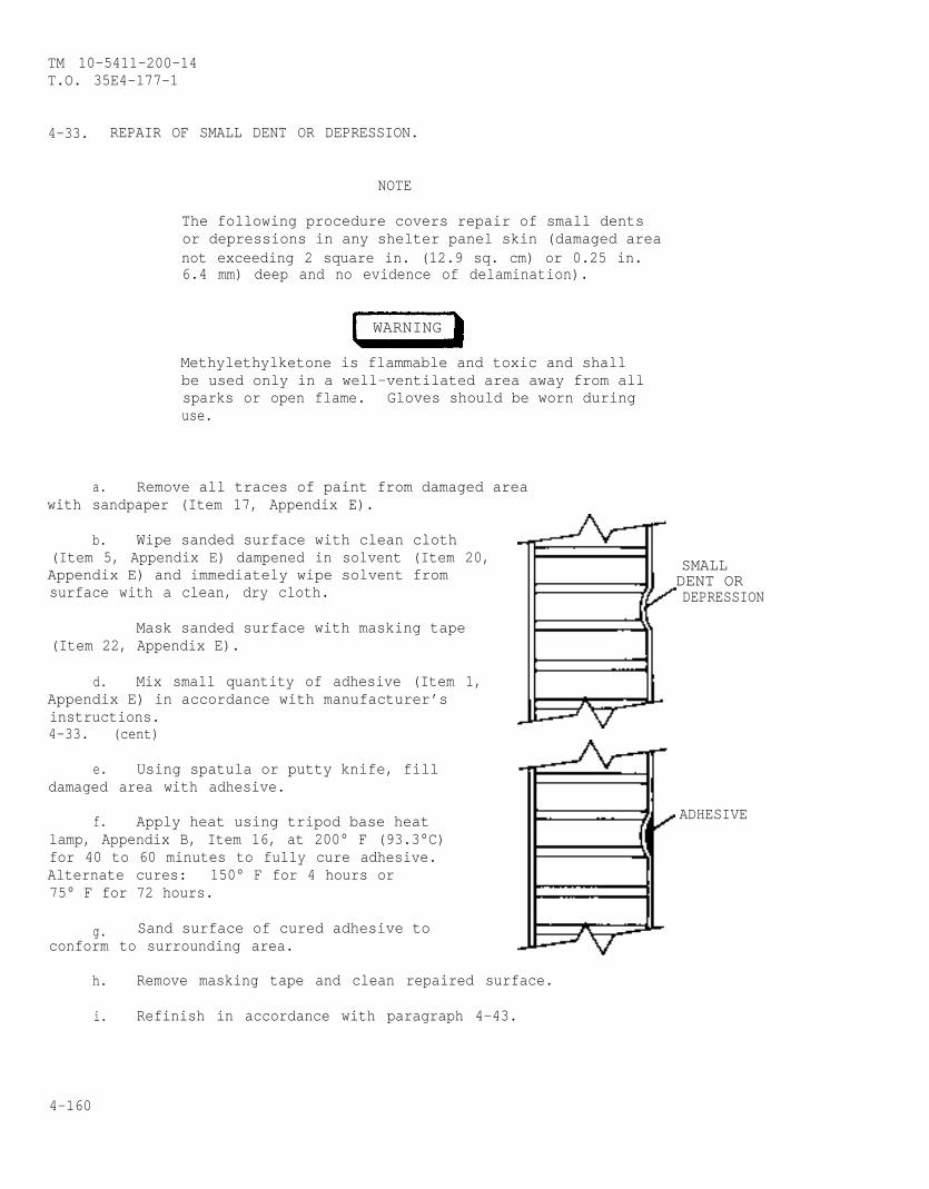
TM 10-5411-200-14T.O. 35E4-177-1
4-33. REPAIR OF SMALL DENT OR DEPRESSION.
NOTE
The following procedure covers repair of small dentsor depressions in any shelter panel skin (damaged areanot exceeding 2 square in. (12.9 sq. cm) or 0.25 in.6.4 mm) deep and no evidence of delamination).
WARNING
Methylethylketone is flammable and toxic and shallbe used only in a well-ventilated area away from allsparks or open flame. Gloves should be worn duringuse.
a. Remove all traces of paint from damaged areawith sandpaper (Item 17, Appendix E).
b. Wipe sanded surface with clean cloth(Item 5, Appendix E) dampened in solvent (Item 20,Appendix E) and immediately wipe solvent fromsurface with a clean, dry cloth.
Mask sanded surface with masking tape(Item 22, Appendix E).
d. Mix small quantity of adhesive (Item 1,Appendix E) in accordance with manufacturer’sinstructions.4-33. (cent)
e. Using spatula or putty knife, filldamaged area with adhesive.
f. Apply heat using tripod base heatlamp, Appendix B, Item 16, at 200° F (93.3°C)for 40 to 60 minutes to fully cure adhesive.Alternate cures: 150° F for 4 hours or75° F for 72 hours.
g. Sand surface of cured adhesive toconform to surrounding area.
h. Remove masking tape and clean repaired surface.
i. Refinish in accordance with paragraph 4-43.
SMALLDENT ORDEPRESSION
ADHESIVE
4-160
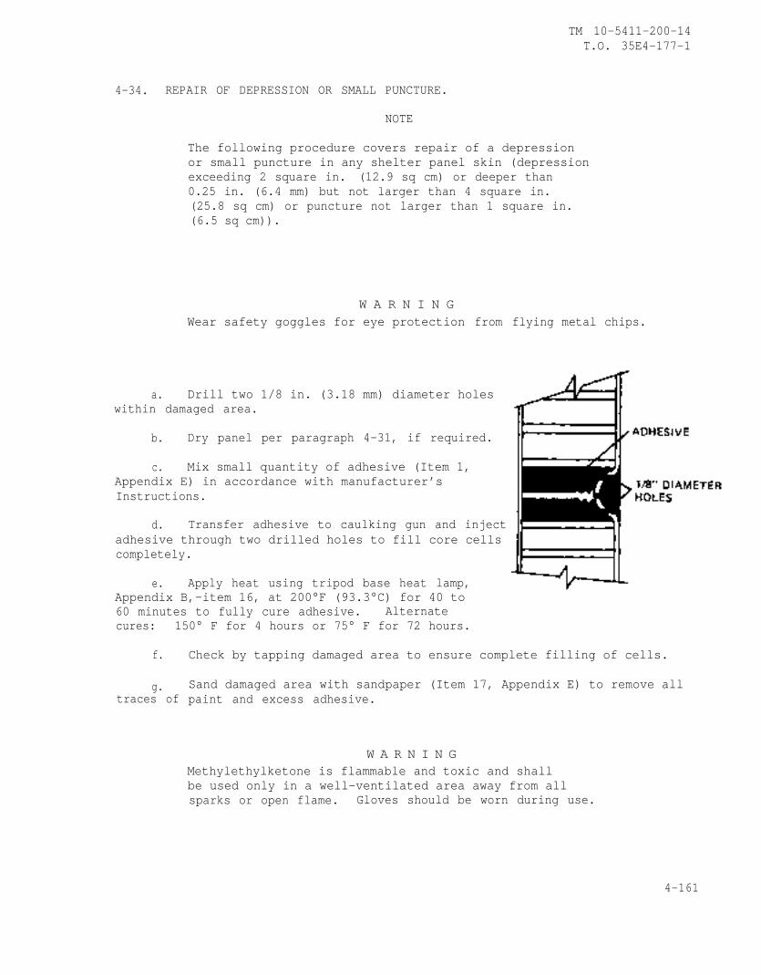
TM 10-5411-200-14T.O. 35E4-177-1
4-34. REPAIR OF DEPRESSION OR SMALL PUNCTURE.
NOTE
The following procedure covers repair of a depressionor small puncture in any shelter panel skin (depressionexceeding 2 square in. (12.9 sq cm) or deeper than0.25 in. (6.4 mm) but not larger than 4 square in.(25.8 sq cm) or puncture not larger than 1 square in.(6.5 sq cm)).
W A R N I N GWear safety goggles for eye protection from
a. Drill two 1/8 in. (3.18 mm) diameter holeswithin damaged area.
b. Dry panel per paragraph 4-31, if required.
c. Mix small quantity of adhesive (Item 1,Appendix E) in accordance with manufacturer’sInstructions.
flying metal chips.
d. Transfer adhesive to caulking gun and injectadhesive through two drilled holes to fill core cellscompletely.
e. Apply heat using tripod base heat lamp,Appendix B,-item 16, at 200°F (93.3°C) for 40 to60 minutes to fully cure adhesive. Alternatecures: 150° F for 4 hours or 75° F for 72 hours.
f.
g.traces of
Check by tapping damaged area to ensure complete filling of cells.
Sand damaged area with sandpaper (Item 17, Appendix E) to remove allpaint and excess adhesive.
W A R N I N GMethylethylketone is flammable and toxic and shallbe used only in a well-ventilated area away from allsparks or open flame. Gloves should be worn during use.
4-161
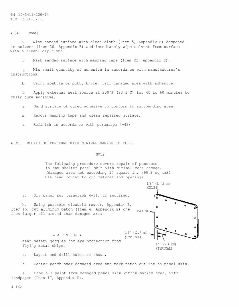
TM 10-5411-200-14T.O. 35E4-177-1
4-34. (cont)
h. Wipe sanded surface with clean cloth (Item 5, Appendix E) dampenedin solvent (Item 20, Appendix E) and immediately wipe solvent from surfacewith a clean, dry cloth.
i. Mask sanded surface with masking tape (Item 22, Appendix E).
j. Mix small quantity of adhesive in accordance with manufacturer’sinstructions.
k. Using spatula or putty knife, fill damaged area with adhesive.
1. Apply external heat source at 200°F (93.3°C) for 40 to 60 minutes tofully cure adhesive.
m. Sand surface of cured adhesive to conform to surrounding area.
n. Remove masking tape and clean repaired surface.
o. Refinish in accordance with paragraph 4-43)
4-35. REPAIR OF PUNCTURE WITH MINIMAL DAMAGE TO CORE.
NOTE
The following procedure covers repair of puncturein any shelter panel skin with minimal core damage,(damaged area not exceeding 14 square in. (90.3 sq cm)).Use hand router to cut patches and openings.
1/8” (3. 18 mm)HOLES
a. Dry panel per paragraph 4-31, if required.
b. Using portable electric router, Appendix B,Item 15, cut aluminum patch (Item 4, Appendix E) oneinch larger all around than damaged area.
PATCH
W A R N I N G 1/2” (12.7 mm)(TYPICAL)
Wear safety goggles for eye protection fromflying metal chips. 1" (25.4 mm)
(TYPICAL)
c. Layout and drill holes as shown.
d. Center patch over damaged area and mark patch outline on panel skin.
e. Sand all paint from damaged panel skin within marked area, withsandpaper (Item 17, Appendix E).
4-162
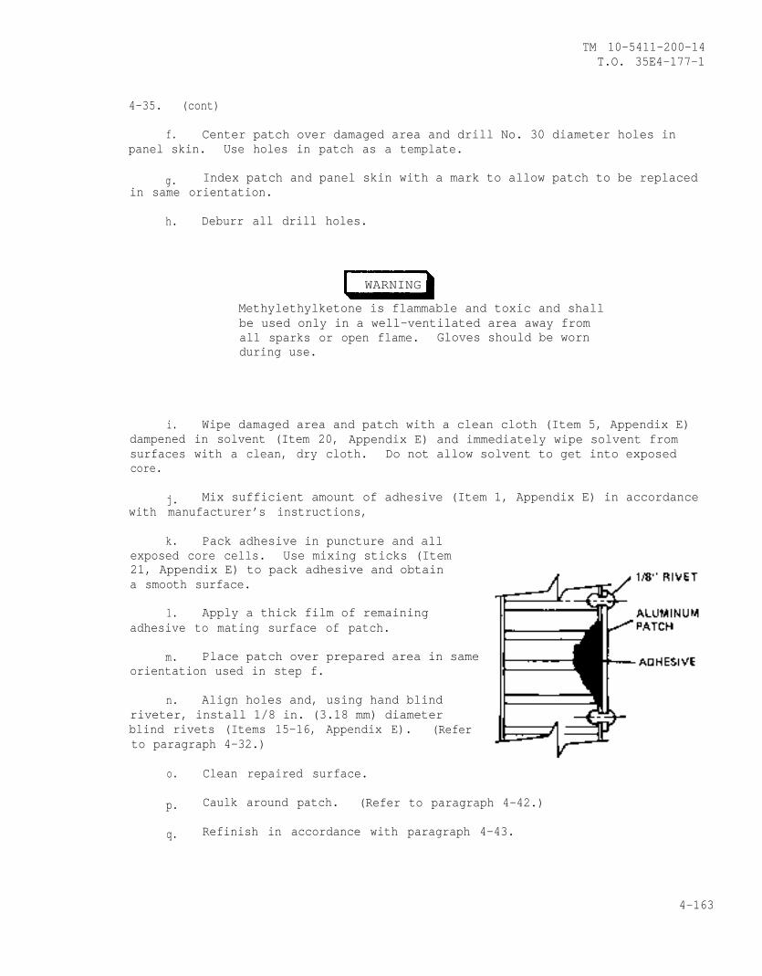
TM 10-5411-200-14T.O. 35E4-177-1
4-35. (cont)
f. Center patch over damaged area and drill No. 30 diameter holes inpanel skin. Use holes in patch as a template.
g. Index patch and panel skin with a mark to allow patch to be replacedin same orientation.
h. Deburr all drill holes.
WARNING
Methylethylketone is flammable and toxic and shallbe used only in a well-ventilated area away fromall sparks or open flame. Gloves should be wornduring use.
i. Wipe damaged area and patch with a clean cloth (Item 5, Appendix E)dampened in solvent (Item 20, Appendix E) and immediately wipe solvent fromsurfaces with a clean, dry cloth. Do not allow solvent to get into exposedcore.
j. Mix sufficient amount of adhesive (Item 1, Appendix E) in accordancewith manufacturer’s instructions,
k. Pack adhesive in puncture and allexposed core cells. Use mixing sticks (Item21, Appendix E) to pack adhesive and obtaina smooth surface.
1. Apply a thick film of remainingadhesive to mating surface of patch.
m. Place patch over prepared area in sameorientation used in step f.
n. Align holes and, using hand blindriveter, install 1/8 in. (3.18 mm) diameterblind rivets (Items 15-16, Appendix E). (Referto paragraph 4-32.)
o. Clean repaired surface.
p. Caulk around patch. (Refer to paragraph 4-42.)
q. Refinish in accordance with paragraph 4-43.
4-163
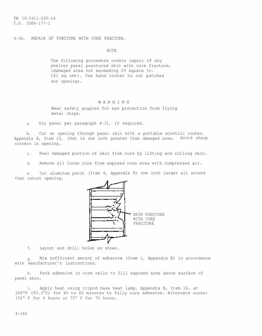
TM 10-5411-200-14T.O. 35E4-177-1
4-36. REPAIR OF PUNCTURE WITH CORE FRACTURE.
NOTE
The following procedure covers repair of anyshelter panel punctured skin with core fracture,(damaged area not exceeding 25 square in.161 sq cm)). Use hand router to cut patchesand openings.
W A R N I N GWear safety goggles for eye protection from flyingmetal chips.
a. Dry panel per paragraph 4-31, if required.
b. Cut an opening through panel skin with a portable electric router,Appendix B, Item 15, that is one inch greater than damaged area. Avoid sharpcorners in opening.
c. Peel damaged portion of skin from core by lifting and rolling skin.
d. Remove all loose core from exposed core area with compressed air.
thane. Cut aluminumcutout opening.
patch (Item 4, Appendix E) one inch larger all around
SKIN PUNCTUREWITH COREFRACTURE
f. Layout and drill holes as shown.
g. Mix sufficient amount of adhesive (Item 1, Appendix E) in accordancewith manufacturer’s instructions.
h. Pack adhesive in core cells to fill exposed area above surface ofpanel skin.
i. Apply heat using tripod base heat lamp, Appendix B, Item 16, at200°F (93.3°C) for 40 to 60 minutes to fully cure adhesive. Alternate cures:150° F for 4 hours or 75° F for 72 hours.
4-164
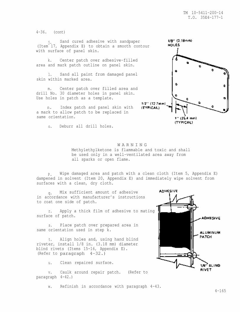
TM 10-5411-200-14T.O. 35E4-177-1
4-36. (cont)
j. Sand cured adhesive with sandpaper(Item 17, Appendix E) to obtain a smooth contourwith surface of panel skin.
k. Center patch over adhesive-filledarea and mark patch outline on panel skin.
1. Sand all paint from damaged panelskin within marked area.
m. Center patch over filled area anddrill No. 30 diameter holes in panel skin.Use holes in patch as a template.
n. Index patch and panel skin witha mark to allow patch to be replaced insame orientation.
o. Deburr all drill holes.
W A R N I N GMethylethylketone is flammable and toxic and shallbe used only in a well-ventilated area away fromall sparks or open flame.
P. Wipe damaged area and patch with a clean cloth (Item 5, Appendix E)dampened in solvent (Item 20, Appendix E) and immediately wipe solvent fromsurfaces with a clean, dry cloth.
q. Mix sufficient amount of adhesivein accordance with manufacturer’s instructionsto coat one side of patch.
r. Apply a thick film of adhesive to matingsurface of patch.
s. Place patch over prepared area insame orientation used in step k.
t. Align holes and, using hand blindriveter, install 1/8 in. (3.18 mm) diameterblind rivets (Items 15-16, Appendix E).(Refer to
u.
v.paragraph
w.
paragraph 4-32.)
Clean repaired surface.
Caulk around repair patch. (Refer to4-42.)
Refinish in accordance with paragraph 4-43.4-165
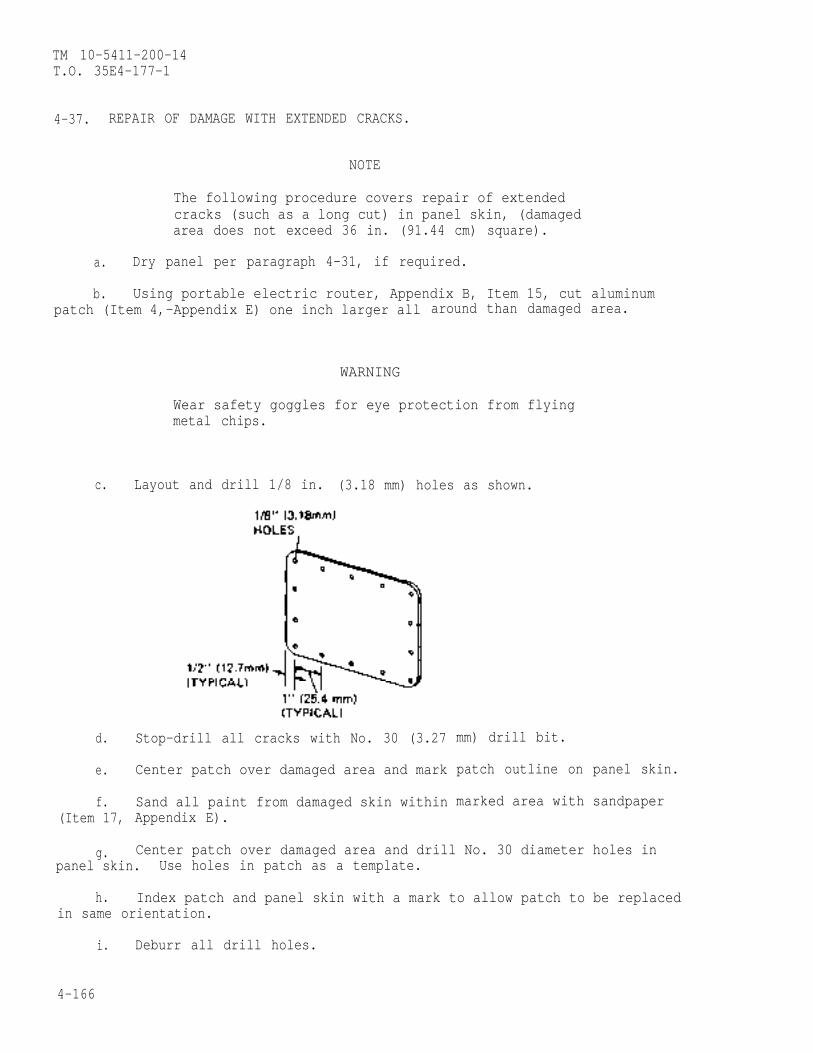
TM 10-5411-200-14T.O. 35E4-177-1
4-37. REPAIR OF DAMAGE WITH EXTENDED CRACKS.
NOTE
The following procedure covers repair of extendedcracks (such as a long cut) in panel skin, (damagedarea does not exceed 36 in. (91.44 cm) square).
a. Dry panel per paragraph 4-31, if required.
b. Using portable electric router, Appendix B, Item 15, cut aluminumpatch (Item 4,-Appendix E) one inch larger all
WARNING
c.
d.
e.
f.(Item 17,
g.
around than damaged area.
Wear safety goggles for eye protection from flyingmetal chips.
Layout and drill 1/8 in. (3.18 mm) holes as shown.
Stop-drill all cracks with No. 30 (3.27
Center patch over damaged area and mark
Sand all paint from damaged skin withinAppendix E).
mm) drill bit.
patch outline on panel skin.
marked area with sandpaper
Center patch over damaged area and drill No. 30 diameter holes inpanel skin. Use holes in patch as a template.
h. Index patch and panel skin with a mark to allow patch to be replacedin same orientation.
i. Deburr all drill holes.
4-166
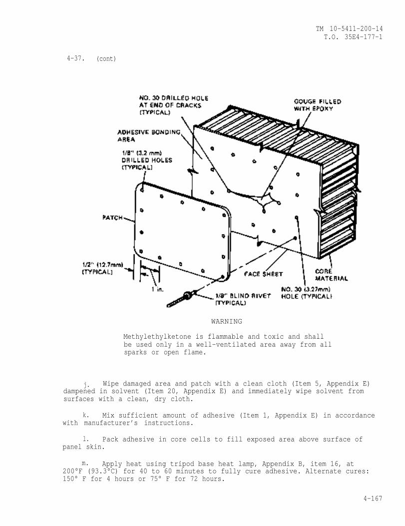
TM 10-5411-200-14T.O. 35E4-177-1
4-37. (cont)
WARNING
Methylethylketone is flammable and toxic and shallbe used only in a well-ventilated area away from allsparks or open flame.
j. Wipe damaged area and patch with a clean cloth (Item 5, Appendix E)dampened in solvent (Item 20, Appendix E) and immediately wipe solvent fromsurfaces with a clean, dry cloth.
k. Mix sufficient amount of adhesive (Item 1, Appendix E) in accordancewith manufacturer’s instructions.
l. Pack adhesive in core cells to fill exposed area above surface ofpanel skin.
m. Apply heat using tripod base heat lamp, Appendix B, item 16, at200°F (93.3°C) for 40 to 60 minutes to fully cure adhesive. Alternate cures:150° F for 4 hours or 75° F for 72 hours.
4-167
TM 10-5411-200-14T.O. 35E4-177-1
4-37. (cont)
n. Sand cured adhesive with sandpaper to obtain a smooth contour withsurface of panel skin.
o. Wipe sanded area and patch with a clean cloth dampened in solventand immediately wipe solvent from surfaces with a clean, dry cloth.
p. Mix sufficient amount of adhesive in accordance with manufacturer’sinstructions to coat one side of patch.
q. Apply a thick film of adhesive to mating surface of patch.
r. Place patch over prepared area in same orientation used in step g.
Align holes and using hand blind riveter, install 1/8 in. (3.18 mm)diameter blind rivets (Items 15-16, Appendix E). (Refer to paragraph 4-32.)
t. Clean repaired surface.
u. Caulk around repair patch. (Refer to paragraph 4-42.)
v. Refinish in accordance with paragraph 4-43.
4-38. REPAIR OF PUNCTURE THROUGH ONE SKIN AND CORE.
NOTE
The following procedure covers repair of panel puncturethrough one skin with core damage, (damaged area does notexceed 100 square in. (645 sq. cm)).
a. Cut an opening through panel skin with portable electric router,Appendix B, Item 15, that is one inch greater than damaged area. Avoid sharpcorners in opening.
NOTE
Openings may be oval, circular, square, or rectangularwith rounded corners.
4-168
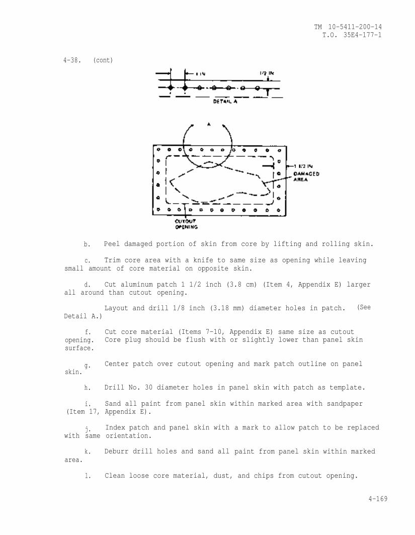
TM 10-5411-200-14T.O. 35E4-177-1
4-38. (cont)
b. Peel damaged portion of skin from core by lifting and rolling skin.
c. Trim core area with a knife to same size as opening while leavingsmall amount of core material on opposite skin.
d. Cut aluminum patch 1 1/2 inch (3.8 cm) (Item 4, Appendix E) largerall around than cutout opening.
Layout and drill 1/8 inch (3.18 mm) diameter holes in patch. (SeeDetail A.)
f. Cut core material (Items 7-10, Appendix E) same size as cutoutopening. Core plug should be flush with or slightly lower than panel skinsurface.
g. Center patch over cutout opening and mark patch outline on panelskin.
h. Drill No. 30 diameter holes in panel skin with patch as template.
i. Sand all paint from panel skin within marked area with sandpaper(Item 17, Appendix E).
j. Index patch and panel skin withwith same orientation.
k. Deburr drill holes and sand allarea.
a mark to allow patch to be replaced
paint from panel skin within marked
l. Clean loose core material, dust, and chips from cutout opening.
4-169
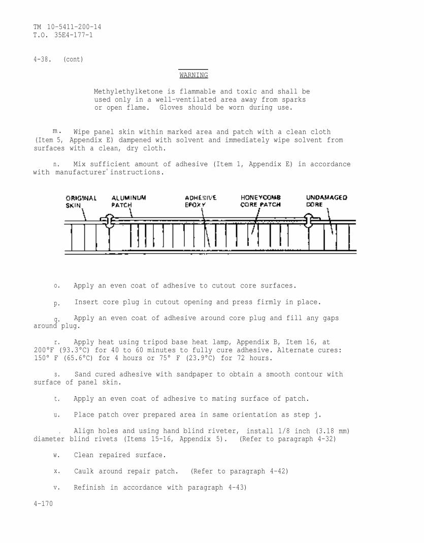
TM 10-5411-200-14T.O. 35E4-177-1
4-38. (cont)
WARNING
m.(Item 5,surfaces
n.
Methylethylketone is flammable and toxic and shall beused only in a well-ventilated area away from sparksor open flame. Gloves should be worn during use.
Wipe panel skin within marked area and patch with a clean clothAppendix E) dampened with solvent and immediately wipe solvent fromwith a clean, dry cloth.
Mix sufficient amount of adhesive (Item 1, Appendix E) in accordancewith manufacturers instructions.
o. Apply an even coat of adhesive to cutout core surfaces.
p. Insert core plug in cutout opening and press firmly in place.
q. Apply an even coat of adhesive around core plug and fill any gapsaround plug.
r. Apply heat using tripod base heat lamp, Appendix B, Item 16, at200°F (93.3°C) for 40 to 60 minutes to fully cure adhesive. Alternate cures:150° F (65.6°C) for 4 hours or 75° F (23.9°C) for 72 hours.
s. Sand cured adhesive with sandpaper to obtain a smooth contour withsurface of panel skin.
t. Apply an even coat of adhesive to mating surface of patch.
u. Place patch over prepared area in same orientation as step j.
. Align holes and using hand blind riveter, install 1/8 inch (3.18 mm)diameter blind rivets (Items 15-16, Appendix 5). (Refer to paragraph 4-32)
w. Clean repaired surface.
x. Caulk around repair patch. (Refer to paragraph 4-42)
v. Refinish in accordance with paragraph 4-43)
4-170
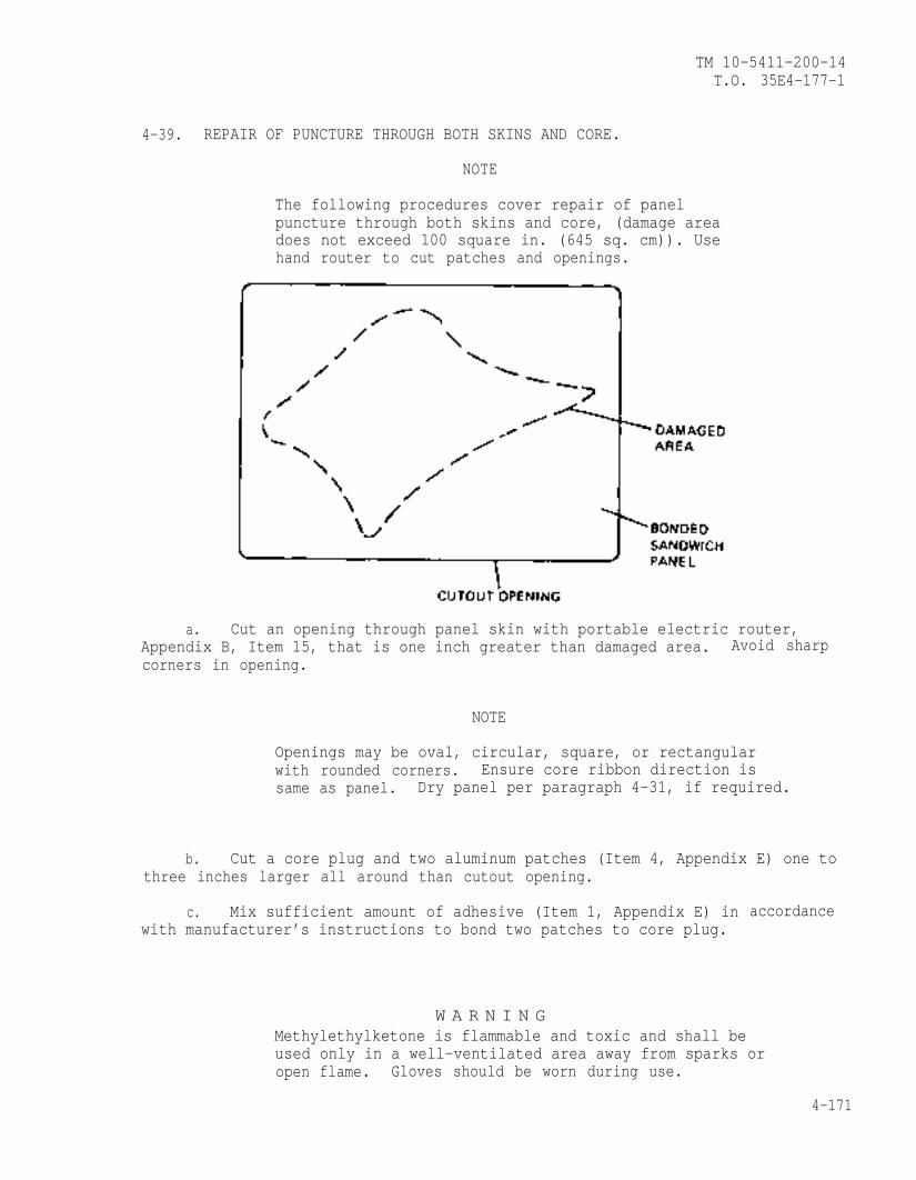
TM 10-5411-200-14T.O. 35E4-177-1
4-39. REPAIR OF PUNCTURE THROUGH BOTH SKINS AND CORE.
NOTE
The following procedures cover repair of panelpuncture through both skins and core, (damage areadoes not exceed 100 square in. (645 sq. cm)). Usehand router to cut patches and openings.
a. Cut an opening through panel skin with portable electric router,Appendix B, Item 15, that is one inch greater than damaged area. Avoid sharpcorners in opening.
NOTE
Openings may be oval, circular, square, or rectangularwith rounded corners. Ensure core ribbon direction issame as panel. Dry panel per paragraph 4-31, if required.
b. Cut a core plug and two aluminum patches (Item 4, Appendix E) one tothree inches larger all around than cutout opening.
c. Mix sufficient amount of adhesive (Item 1, Appendix E) inwith manufacturer’s instructions to bond two patches to core plug.
W A R N I N G
accordance
Methylethylketone is flammable and toxic and shall beused only in a well-ventilated area away from sparks oropen flame. Gloves should be worn during use.
4-171
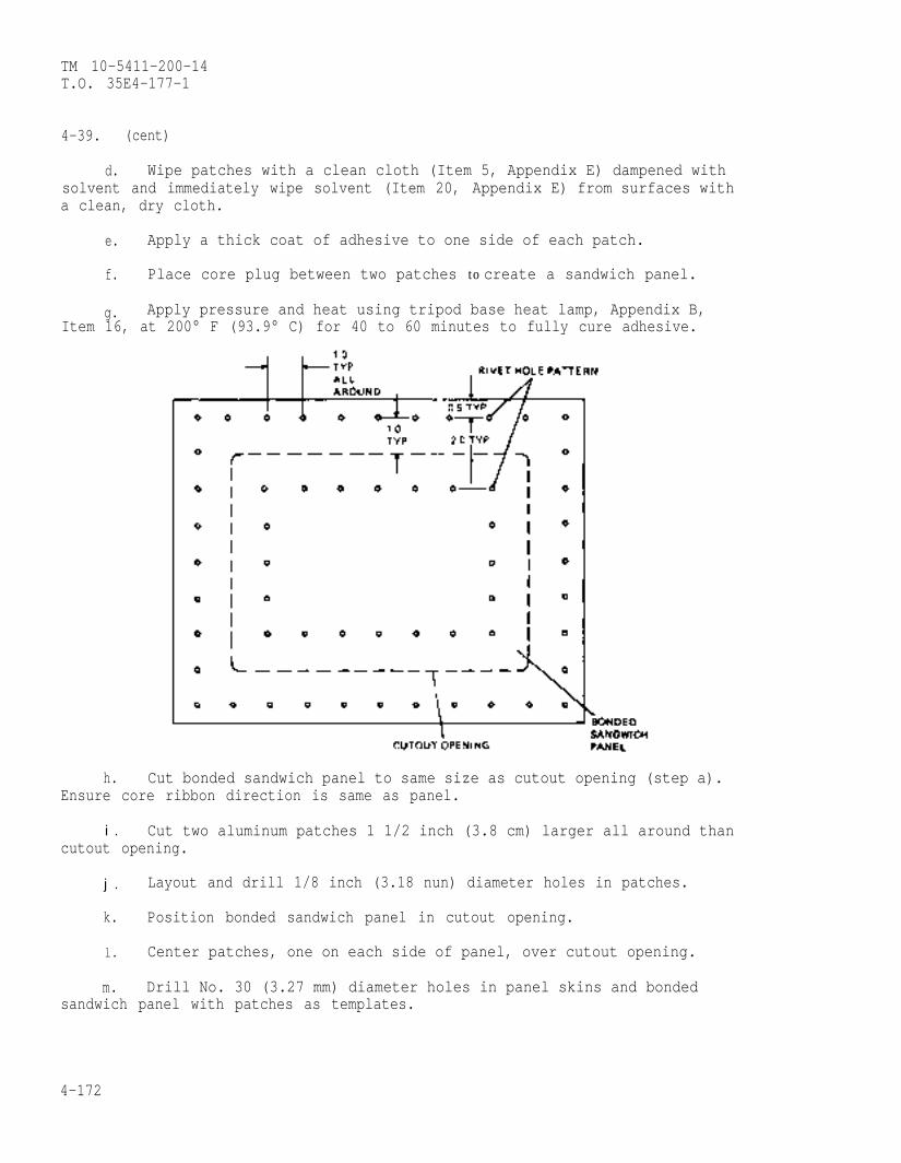
TM 10-5411-200-14T.O. 35E4-177-1
4-39. (cent)
d. Wipe patches with a clean cloth (Item 5, Appendix E) dampened withsolvent and immediately wipe solvent (Item 20, Appendix E) from surfaces witha clean, dry cloth.
e. Apply a thick coat of adhesive to one side of each patch.
f. Place core plug between two patches to create a sandwich panel.
g. Apply pressure and heat using tripod base heat lamp, Appendix B,Item 16, at 200° F (93.9° C) for 40 to 60 minutes to fully cure adhesive.
h. Cut bonded sandwich panel to same size as cutout opening (step a).Ensure core ribbon direction is same as panel.
i . Cut two aluminum patches 1 1/2 inch (3.8 cm) larger all around thancutout opening.
j . Layout and drill 1/8 inch (3.18 nun) diameter holes in patches.
k. Position bonded sandwich panel in cutout opening.
l. Center patches, one on each side of panel, over cutout opening.
m. Drill No. 30 (3.27 mm) diameter holes in panel skins and bondedsandwich panel with patches as templates.
4-172
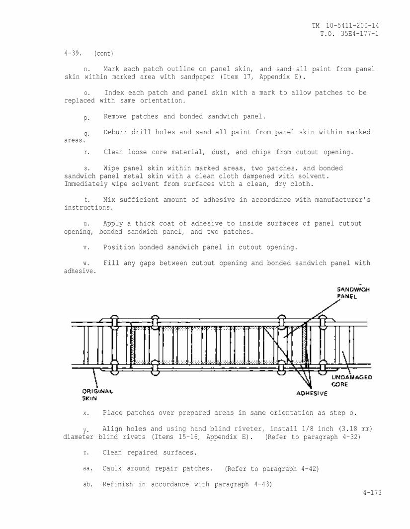
TM 10-5411-200-14T.O. 35E4-177-1
4-39. (cont)
n. Mark each patch outline on panel skin, and sand all paint from panelskin within marked area with sandpaper (Item 17, Appendix E).
o. Index each patch and panel skin with a mark to allow patches to bereplaced with same orientation.
p. Remove patches and bonded sandwich panel.
q. Deburr drill holes and sand all paint from panel skin within markedareas.
r. Clean loose core material, dust, and chips from cutout opening.
s. Wipe panel skin within marked areas, two patches, and bondedsandwich panel metal skin with a clean cloth dampened with solvent.Immediately wipe solvent from surfaces with a clean, dry cloth.
t. Mix sufficient amount of adhesive in accordance with manufacturer’sinstructions.
u. Apply a thick coat of adhesive to inside surfaces of panel cutoutopening, bonded sandwich panel, and two patches.
v. Position bonded sandwich panel in cutout opening.
w. Fill any gaps between cutout opening and bonded sandwich panel withadhesive.
x. Place patches over prepared areas in same orientation as step o.
y. Align holes and using hand blind riveter, install 1/8 inch (3.18 mm)diameter blind rivets (Items 15-16, Appendix E). (Refer to paragraph 4-32)
z. Clean repaired surfaces.
aa. Caulk around repair patches. (Refer to paragraph 4-42)
ab. Refinish in accordance with paragraph 4-43)4-173
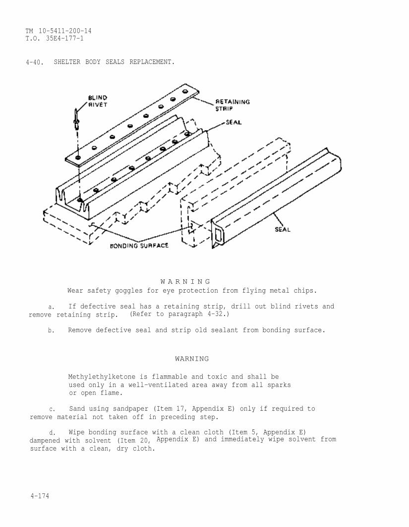
TM 10-5411-200-14T.O. 35E4-177-1
4-40. SHELTER BODY SEALS REPLACEMENT.
W A R N I N GWear safety goggles for eye protection from flying metal chips.
a. If defective seal has a retaining strip, drill out blind rivets andremove retaining strip. (Refer to paragraph 4-32.)
b. Remove defective seal and strip old sealant from bonding surface.
WARNING
Methylethylketone is flammable and toxic and shall beused only in a well-ventilated area away from all sparksor open flame.
c. Sand using sandpaper (Item 17, Appendix E) only if required toremove material not taken off in preceding step.
d. Wipe bonding surface with a clean cloth (Item 5, Appendix E)dampened with solvent (Item 20, Appendix E) and immediately wipe solvent fromsurface with a clean, dry cloth.
4-174
TM 10-5411-200-14T.O. 35E4-177-1
4-40. (cont)
CAUTION
Seals shall not be washed with any aromatic hydrocarbon(such as benzene, toluene, or xylene) which will causedeterioration.
e. Clean seal with a lint-free cloth by dry wiping prior to bonding.
f. Brush sealant (Item 18, Appendix E) on mating surfaces of seal andbonding surface.
g. When sealant is tacky (approximately 5 minutes), place seal inposition, press firmly to seat and ensure contact with mating surface.
h. If seal is the type that has a retaining strip, seal shall be bondedprior to riveting retaining strip. (Refer to paragraph 4-32 for blind rivetinstallation.)
i. After installing rivets, using hand blind riveter, cover rivets andseal with sealing compound (Item 19, Appendix E).
4-41. THREADED INSERTS REPLACEMENT.
NOTE
Inserts installed in extrusions are not potted. Forremoval of these inserts, perform steps a and b only.Knock out insert and replace with same type.
a. Depending on insert size, select a drill bit in size range listedbelow.
Insert Thread Size Drill Size Rangeinches (mm)
10-32 7/16-15/32 (11/12.4)1/4-28 17/32-21/32 (13.5/16/7)5/16-24 39/64-21/32 (15.5/16.7)3/8-24 43/64-23/32 (17/18.3)
4-175
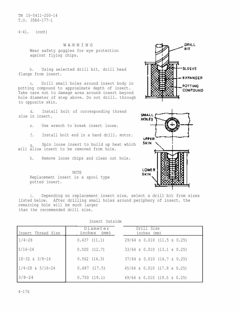
TM 10-5411-200-14T.O. 35E4-177-1
4-41. (cont)
W A R N I N GWear safety goggles for eyeagainst flying chips.
protection
b. Using selected drill bit, drill headflange from insert.
c. Drill small holes around insert body inpotting compound to approximate depth of insert.Take care not to damage area around insert beyondhole diameter of step above. Do not drill. throughto opposite skin.
d. Install bolt of corresponding threadsize in insert.
e. Use wrench to break insert loose.
f. Install bolt end in a hand drill. motor.
g. Spin loose insert to build up heat whichwill allow insert to be removed from hole.
h. Remove loose chips and clean out hole.
NOTEReplacement insert is a spool typepotted insert.
i. Depending on replacement insert size, select a drill bit from sizeslisted below. After drilling small holes around periphery of insert, theremaining hole will be much largerthan the recommended drill size.
Insert Outside
Insert Thread Size
1/4-28
5/16-24
10-32 & 3/8-16
1/4-28 & 5/16-24
3/8-24
Diameter Drill Sizeinches (mm) inches (mm)
0.437 (11.1) 29/64 ± 0.010 (11.5 ± 0.25)
0.500 (12.7) 33/64 ± 0.010 (13.1 ± 0.25)
0.562 (14.3) 37/64 ± 0.010 (14.7 ± 0.25)
0.687 (17.5) 45/64 ± 0.010 (17.9 ± 0.25)
0.750 (19.1) 49/64 ± 0.010 (19.5 ± 0.25)
4-176
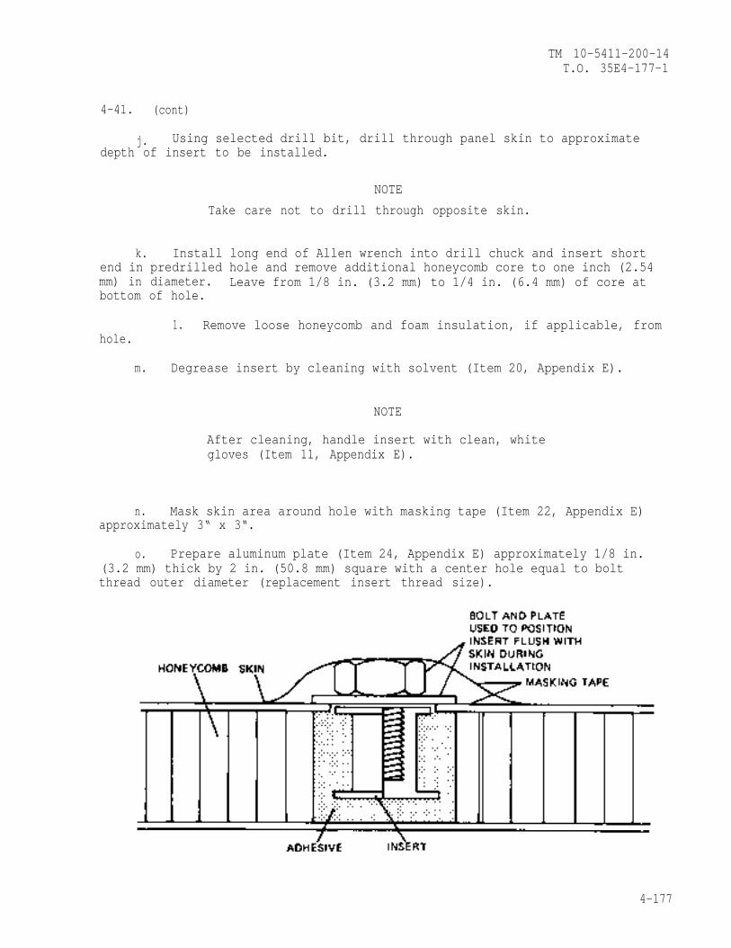
TM 10-5411-200-14T.O. 35E4-177-1
4-41. (cont)
j. Using selected drill bit, drill through panel skin to approximatedepth of insert to be installed.
NOTE
Take care not to drill through opposite skin.
k. Install long end of Allen wrench into drill chuck and insert shortend in predrilled hole and remove additional honeycomb core to one inch (2.54mm) in diameter. Leave from 1/8 in. (3.2 mm) to 1/4 in. (6.4 mm) of core atbottom of hole.
hole.
m.
n.
1. Remove loose honeycomb and foam insulation, if applicable, from
Degrease insert by cleaning with solvent (Item 20, Appendix E).
NOTE
After cleaning, handle insert with clean, whitegloves (Item 11, Appendix E).
Mask skin area around hole with masking tape (Item 22, Appendix E)approximately 3“ x 3“.
o. Prepare aluminum plate (Item 24, Appendix E) approximately 1/8 in.(3.2 mm) thick by 2 in. (50.8 mm) square with a center hole equal to boltthread outer diameter (replacement insert thread size).
4-177
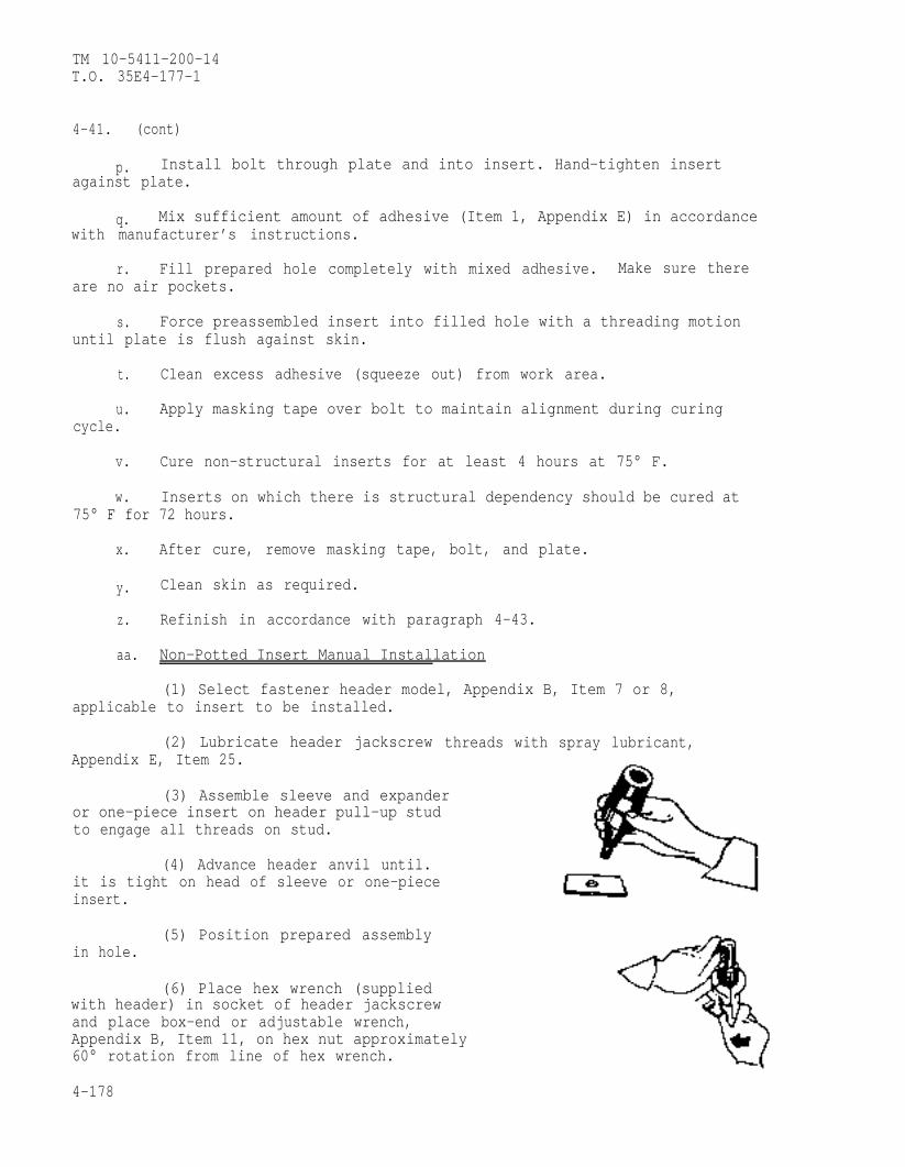
TM 10-5411-200-14T.O. 35E4-177-1
4-41. (cont)
p. Install bolt through plate and into insert. Hand-tighten insertagainst plate.
q. Mix sufficient amount of adhesive (Item 1, Appendix E) in accordancewith manufacturer’s instructions.
r. Fill prepared hole completely with mixed adhesive. Make sure thereare no air pockets.
s. Force preassembled insert into filled hole with a threading motionuntil plate is flush against skin.
t. Clean excess adhesive (squeeze out) from work area.
u. Apply masking tape over bolt to maintain alignment during curingcycle.
v. Cure non-structural inserts for at least 4 hours at 75° F.
w. Inserts on which there is structural dependency should be cured at75° F for 72 hours.
x. After cure, remove masking tape, bolt, and plate.
y. Clean skin as required.
z. Refinish in accordance with paragraph 4-43.
aa. Non-Potted Insert Manual Installation
(1) Select fastener header model, Appendix B, Item 7 or 8,applicable to insert to be installed.
(2) Lubricate header jackscrew threads with spray lubricant,Appendix E, Item 25.
(3) Assemble sleeve and expanderor one-piece insert on header pull-up studto engage all threads on stud.
(4) Advance header anvil until.it is tight on head of sleeve or one-pieceinsert.
(5) Position prepared assemblyin hole.
(6) Place hex wrench (suppliedwith header) in socket of header jackscrewand place box-end or adjustable wrench,Appendix B, Item 11, on hex nut approximately60° rotation from line of hex wrench.
4-178
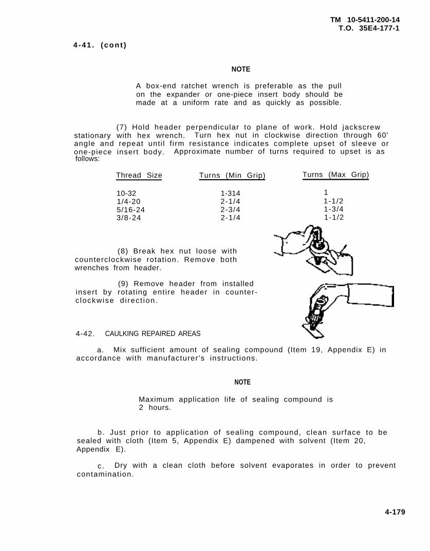
TM 10-5411-200-14T.O. 35E4-177-1
4 -41 . (cont )
NOTE
A box-end ratchet wrench is preferable as the pullon the expander or one-piece insert body should bemade at a uniform rate and as quickly as possible.
(7) Hold header perpendicular to plane of work. Hold jackscrewstationary with hex wrench. Turn hex nut in clockwise direction through 60'angle and repeat unt i l f i rm resistance indicates complete upset of sleeve orone-piece insert body. Approximate number of turns required to upset is asfollows:
Thread Size Turns (Min Grip) Turns (Max Grip)
10-32 1-3141/4-20 2-1/45/16-24 2-3/43/8-24 2-1/4
11-1/21-3/41-1/2
(8) Break hex nut loose withcounterclockwise rotat ion. Remove bothwrenches from header.
(9) Remove header from installedinsert by rotat ing entire header in counter-c lockwise d i rec t ion.
4-42. CAULKING REPAIRED AREAS
a. Mix sufficient amount of sealing compound (Item 19, Appendix E) inaccordance with manufacturer 's instruct ions.
NOTE
Maximum application life of sealing compound is2 hours.
b. Just pr ior to appl icat ion of seal ing compound, clean surface to besealed with cloth (Item 5, Appendix E) dampened with solvent (Item 20,Appendix E).
c . Dry with a clean cloth before solvent evaporates in order to preventcontamination.
4-179
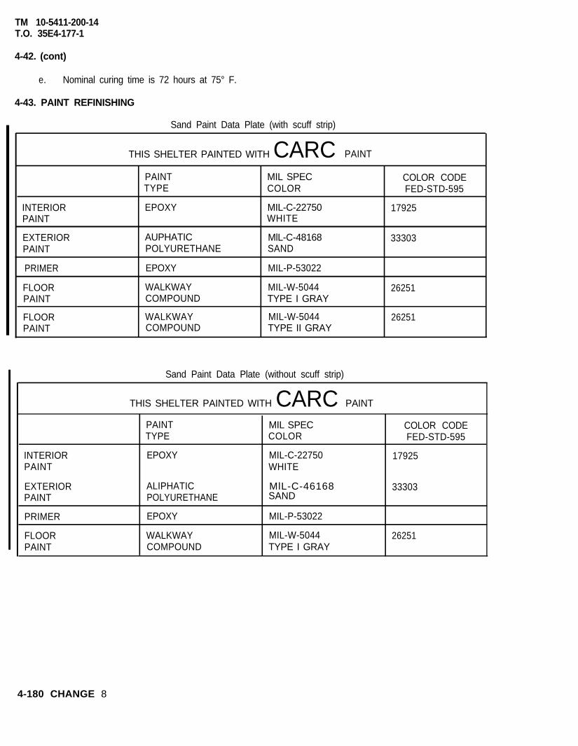
TM 10-5411-200-14T.O. 35E4-177-1
4-42. (cont)
e. Nominal curing time is 72 hours at 75° F.
4-43. PAINT REFINISHING
INTERIORPAINT
EXTERIORPAINT
PRIMER
FLOORPAINT
FLOORPAINT
Sand Paint Data Plate (with scuff strip)
THIS SHELTER PAINTED WITH CARC PAINT
PAINT MIL SPEC COLOR CODETYPE COLOR FED-STD-595
EPOXY MIL-C-22750 17925WHITE
AUPHATIC MlL-C-48168 33303POLYURETHANE SAND
EPOXY MIL-P-53022
WALKWAY MIL-W-5044 26251COMPOUND TYPE I GRAY
WALKWAY MIL-W-5044 26251COMPOUND TYPE II GRAY
Sand Paint Data Plate (without scuff strip)
THIS SHELTER PAINTED WITH CARC PAINT
INTERIORPAINT
PAINTTYPE
EPOXY
MIL SPECCOLOR
MIL-C-22750WHITE
COLOR CODEFED-STD-595
17925
EXTERIOR ALIPHATIC MlL-C-46168 33303PAINT POLYURETHANE SAND
PRIMER EPOXY MIL-P-53022
FLOOR WALKWAY MIL-W-5044 26251PAINT COMPOUND TYPE I GRAY
4-180 CHANGE 8
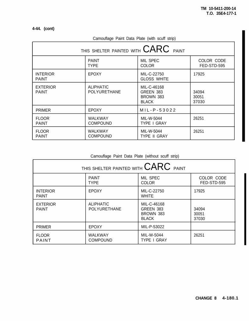
4-44. (cont)
TM 10-5411-200-14T.O. 35E4-177-1
Camouflage Paint Data Plate (with scuff strip)
THIS SHELTER PAINTED WITH CARC PAINT
INTERIORPAINT
EXTERIORPAINT
PRIMER
FLOORPAINT
FLOORPAINT
PAINTTYPE
EPOXY
ALIPHATICPOLYURETHANE
EPOXY
WALKWAYCOMPOUND
WALKWAYCOMPOUND
MIL SPECCOLOR
MIL-C-22750GLOSS WHITE
MIL-C-46168GREEN 383BROWN 383BLACK
M I L - P - 5 3 0 2 2
MIL-W-5044TYPE I GRAY
MIL-W-5044TYPE II GRAY
COLOR CODEFED-STD-595
17925
340943005137030
26251
26251
Camouflage Paint Data Plate (without scuff strip)
THIS SHELTER PAINTED WITH CARC PAINT
INTERIORPAINT
EXTERIORPAINT
PRIMER
FLOORPAINT
PAINTTYPE
EPOXY
ALIPHATICPOLYURETHANE
EPOXY
WALKWAYCOMPOUND
MIL SPECCOLOR
MlL-C-22750WHITE
MIL-C-46168GREEN 383BROWN 383BLACK
MIL-P-53022
MIL-W-5044TYPE I GRAY
COLOR CODEFED-STD-595
17925
340943005137030
26251
CHANGE 8 4-180.1
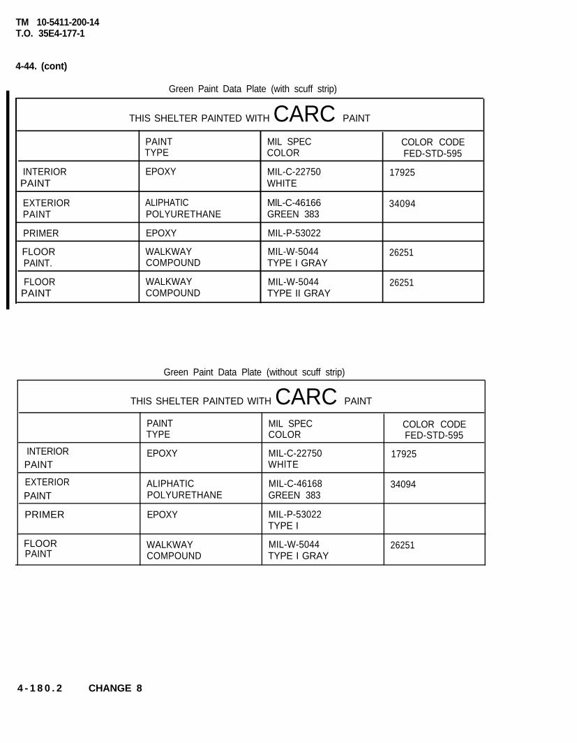
TM 10-5411-200-14T.O. 35E4-177-1
4-44. (cont)
Green Paint Data Plate (with scuff strip)
THIS SHELTER PAINTED WITH CARC PAINT
INTERIORPAINT
PAINTTYPE
EPOXY
MIL SPECCOLOR
MIL-C-22750WHITE
COLOR CODEFED-STD-595
17925
EXTERIORPAINT
PRIMER
FLOORPAINT.
FLOORPAINT
ALIPHATICPOLYURETHANE
EPOXY
WALKWAYCOMPOUND
WALKWAYCOMPOUND
MlL-C-46166 34094GREEN 383
MIL-P-53022
MIL-W-5044 26251TYPE I GRAY
MIL-W-5044 26251TYPE II GRAY
Green Paint Data Plate (without scuff strip)
THIS SHELTER PAINTED WITH CARC PAINT
INTERIORPAINT
PAINTTYPE
MIL SPEC COLOR CODECOLOR FED-STD-595
EPOXY MIL-C-22750WHlTE
17925
ALIPHATIC MIL-C-46168POLYURETHANE GREEN 383
34094EXTERIORPAINT
PRIMER
FLOORPAINT
EPOXY MIL-P-53022TYPE I
WALKWAY MIL-W-5044COMPOUND TYPE I GRAY
26251
4 - 1 8 0 . 2 CHANGE 8

TM 10-5411-200-14T.O. 35E4-177-1
4-43. (cont)
NOTE
Paint data is also listed on color code identification plate on personnel endwall.
a. Prepare surface for painting by removing all corrosion by wire brushing, sanding, or application ofcorrosion-removing compounds.
b. Chemically treat all aluminum parts in accordance with MIL-C-5541, Class 1A.
c. Areas to be painted shall be free of dust, residue, and cleaning compounds before refinishing.
d. Solvent, primer, or paint shall not be applied to seals or non-metal parts. Mask such parts with maskingtape for protection.
NOTE
Check paint data plate for primer used.
e. Mix and apply epoxy primer coating in accordance with MIL-P-53022 or MIL-P-23377.
f. Allow to dry thoroughly before applying finish coat.
g. Mix and apply paint in accordance with manufacturers instructions.
h. Apply two separate, uniform coats. Make sure there are no sags or runs.
i. Allow first coat to dry before applying second coat-
4-44. DECAL REMOVAL AND REPLACEMENT
a. Use a putty knife (or similar tool) to peel decals off all surfaces.
b. Clean all decal mounting surfaces.
c. Apply sealing compound, Item 19, Appendix E, to the rear of decals and position on mounting surfaces.
CHANGE 8 4-181
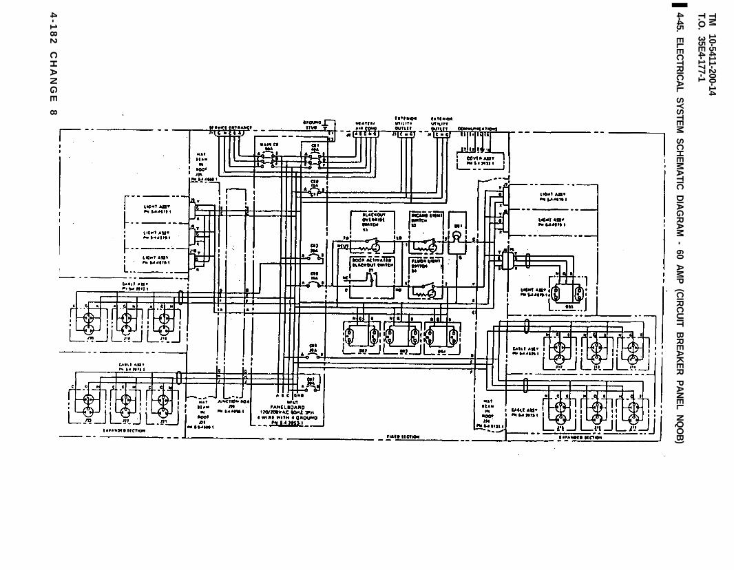
TM
10-5411-200-14T.O
. 35E
4-177-1
4-45. ELE
CTR
ICA
L SY
STE
M S
CH
EM
ATIC
DIA
GR
AM
- 60 AM
P (C
IRC
UIT B
RE
AK
ER
PA
NE
L NQ
OB
)
4-1
82
C
HA
NG
E
8

TM
10-5411-200-14T.O
. 35E4-177-1
4-45A. E
LEC
TRIC
AL S
YS
TEM
SC
HE
MA
TIC D
IAG
RA
M - 60 A
MP
(CIR
CU
IT BR
EA
KE
R P
AN
EL N
QO
D)
CH
AN
GE
84-182.1/(4-182.2
blank)

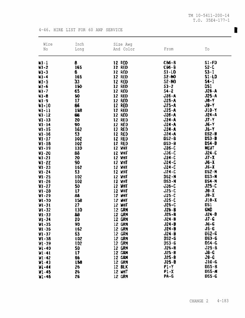
TM 10-5411-200-14T.O. 35E4-177-1
4-46. HIRE LIST FOR 60 ANP SERVICE
Wire Inch Size AwgNo Long And Color From To
CHANGE 2 4-183
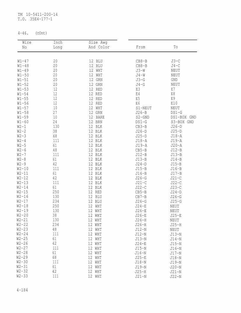
TM 10-5411-200-14T.O. 35E4-177-1
4-46. (cOnt)
Wire Inch Size AwgNo Long And Color From To
W1-47W1-48W1-49W1-50W1-51W1-52W1-53W1-54W1-55W1-56W1-57W1-58W1-59W1-60W2-1W2-2W2-3W2-4W2-5W2-6W2-7W2-8W2-9W2-10W2-11W2-12W2-13W2-14W2-15W2-16W2-17W2-18W2-19W2-20W2-21W2-22W2-23W2-24W2-25W2-26W2-27W2-28W2-29W2-30W2-31W2-32W2-33
4-184
20202020202012121212102710241303868111614811161421116142111612501302342501303813023448111614211161681116142111
12 BLU12 BLU12 WHT12 WHT12 GRN12 GRN12 RED12 RED12 RED12 RED12 WHT12 GRN12 BARE12 BRN12 BLK12 BLK12 BLK12 BLK12 BLK12 BLK12 BLK12 BLK12 BLK12 BLK12 BLK12 BLK12 BLK12 BLK12 RED12 BLU12 BLU12 WHT12 WHT12 WHT12 WHT12 WHT12 WHT12 WHT12 WHT12 WHT12 WHT12 WHT12 WHT12 WHT12 WHT12 WHT12 WHT
CB8-BCB8-BJ3-WJ4-WJ3-GJ4-GE3E4E5E6S1-NEUTJ26-BS2-GNDDS1-GCB3-BJ26-DJ25-DJ18-AJ19-ACB5-BJ12-BJ13-BJ24-DJ15-BJ16-BJ26-GJ21-CJ22-CCB5-BCB7-BJ26-GJ24-EJ26-EJ26-EJ26-HJ26-HJ12-NJ12-NJ13-NJ24-EJ15-NJ16-NJ25-EJ18-NJ19-NJ25-HJ21-N
J3-CJ4-CNEUTNEUTGNDNEUTE7E8E9E10NEUTDS1-GDS1-BOX GNDS3-BOX GNDJ26-DJ25-DJ18-AJ19-AJ20-AJ12-BJ13-BJ14-BJ15-BJ16-BJ17-BJ21-CJ22-CJ23-CJ24-DJ26-GJ25-GNEUTNEUTJ25-ENEUTJ25-HNEUTJ13-NJ14-NJ15-NJ16-NJ17-NJ18-NJ19-NJ20-NJ21-NJ22-N
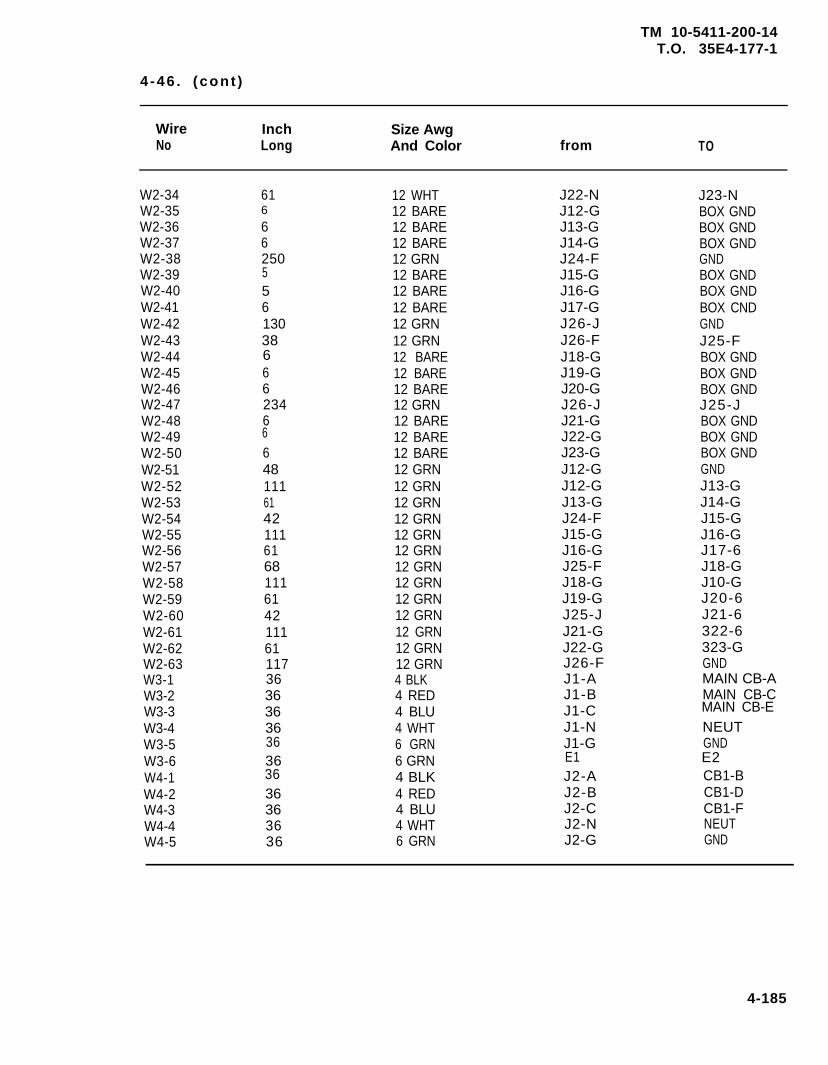
TM 10-5411-200-14T.O. 35E4-177-1
4 -46 . (cont )
Wire InchNo Long
Size AwgAnd Color from TO
W2-34W2-35W2-36W2-37W2-38W2-39W2-40W2-41W2-42W2-43W2-44W2-45W2-46W2-47W2-48W2-49W2-50W2-51W2-52W2-53W2-54W2-55W2-56W2-57W2-58W2-59W2-60W2-61W2-62W2-63W3-1W3-2W3-3W3-4W3-5W3-6W4-1W4-2W4-3W4-4W4-5
616
662505561303866623466648111614211161681116142111611173636363636363636363636
12 WHT12 BARE12 BARE12 BARE12 GRN12 BARE12 BARE12 BARE12 GRN12 GRN12 BARE12 BARE12 BARE12 GRN12 BARE12 BARE12 BARE12 GRN12 GRN12 GRN12 GRN12 GRN12 GRN12 GRN12 GRN12 GRN12 GRN12 GRN12 GRN12 GRN4 BLK4 RED4 BLU4 WHT6 GRN6 GRN4 BLK4 RED4 BLU4 WHT6 GRN
J22-NJ12-GJ13-GJ14-GJ24-FJ15-GJ16-GJ17-GJ26-JJ26-FJ18-GJ19-GJ20-GJ26-JJ21-GJ22-GJ23-GJ12-GJ12-GJ13-GJ24-FJ15-GJ16-GJ25-FJ18-GJ19-GJ25-JJ21-GJ22-GJ26-FJ1-AJ1-BJ1-CJ1-NJ1-GE1J2-AJ2-BJ2-CJ2-NJ2-G
J23-NBOX GNDBOX GNDBOX GNDGNDBOX GNDBOX GNDBOX CNDGNDJ25-FBOX GNDBOX GNDBOX GNDJ25-JBOX GNDBOX GNDBOX GNDGNDJ13-GJ14-GJ15-GJ16-GJ17-6J18-GJ10-GJ20-6J21-6322-6323-GGNDMAIN CB-AMAIN CB-CMAIN CB-ENEUTGNDE2CB1-BCB1-DCB1-FNEUTGND
4-185
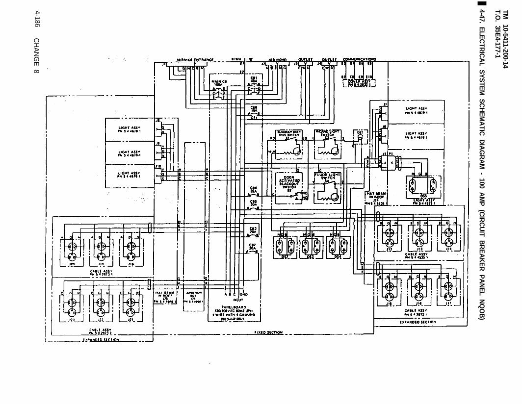
TM
10-5411-200-14T.O
. 35E4-177-1
4-47. ELE
CTR
ICA
L SY
STE
M S
CH
EM
ATIC
DIA
GR
AM
- 100 AM
P (C
IRC
UIT B
RE
AK
ER
PA
NE
L NQ
OB
)
4-186C
HAN
GE 8
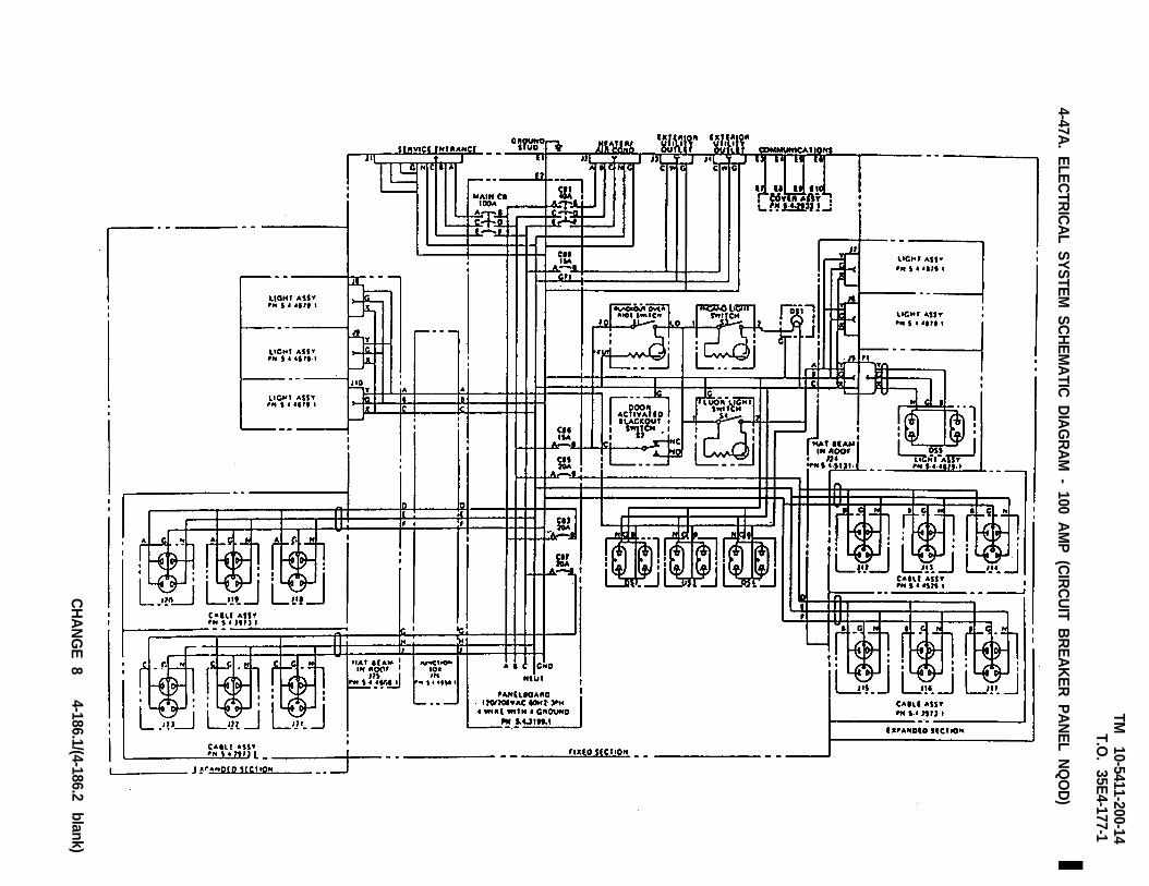
TM
10-5411-200-14T.O
. 35E
4-177-1
4-47A. E
LEC
TRIC
AL S
YS
TEM
SC
HE
MA
TIC D
IAG
RA
M - 100 A
MP
(CIR
CU
IT BR
EA
KE
R P
AN
EL N
QO
D)
CH
AN
GE
84-186.1/(4-186.2
blank)

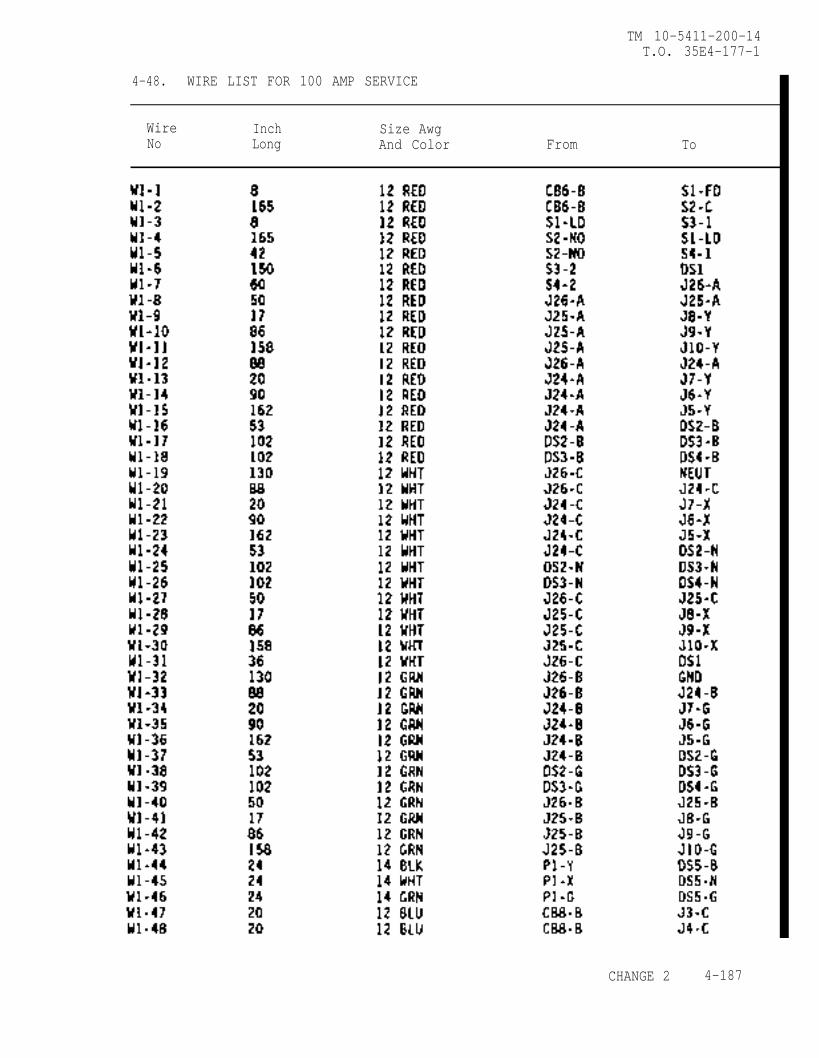
TM 10-5411-200-14T.O. 35E4-177-1
4-48. WIRE LIST FOR 100 AMP SERVICE
Wire Inch Size AwgNo Long And Color From To
CHANGE 2 4-187
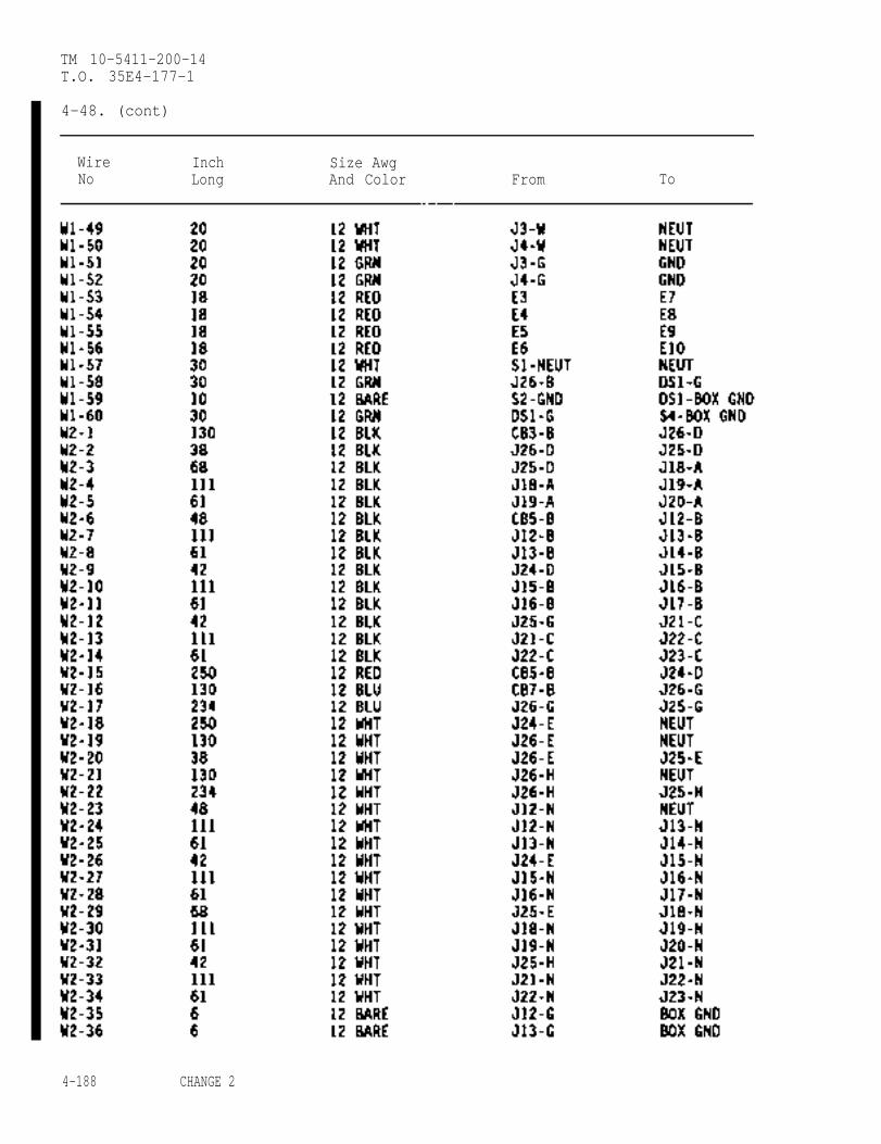
TM 10-5411-200-14T.O. 35E4-177-1
4-48. (cont)
Wire Inch Size AwgNo Long And Color From To
4-188 CHANGE 2

TM 10-5411-200-14T.O. 35E4-177-1
4-48. (cont)
Wire Inch Size AwgNo Long And Color From To
CHANGE 2 4-189
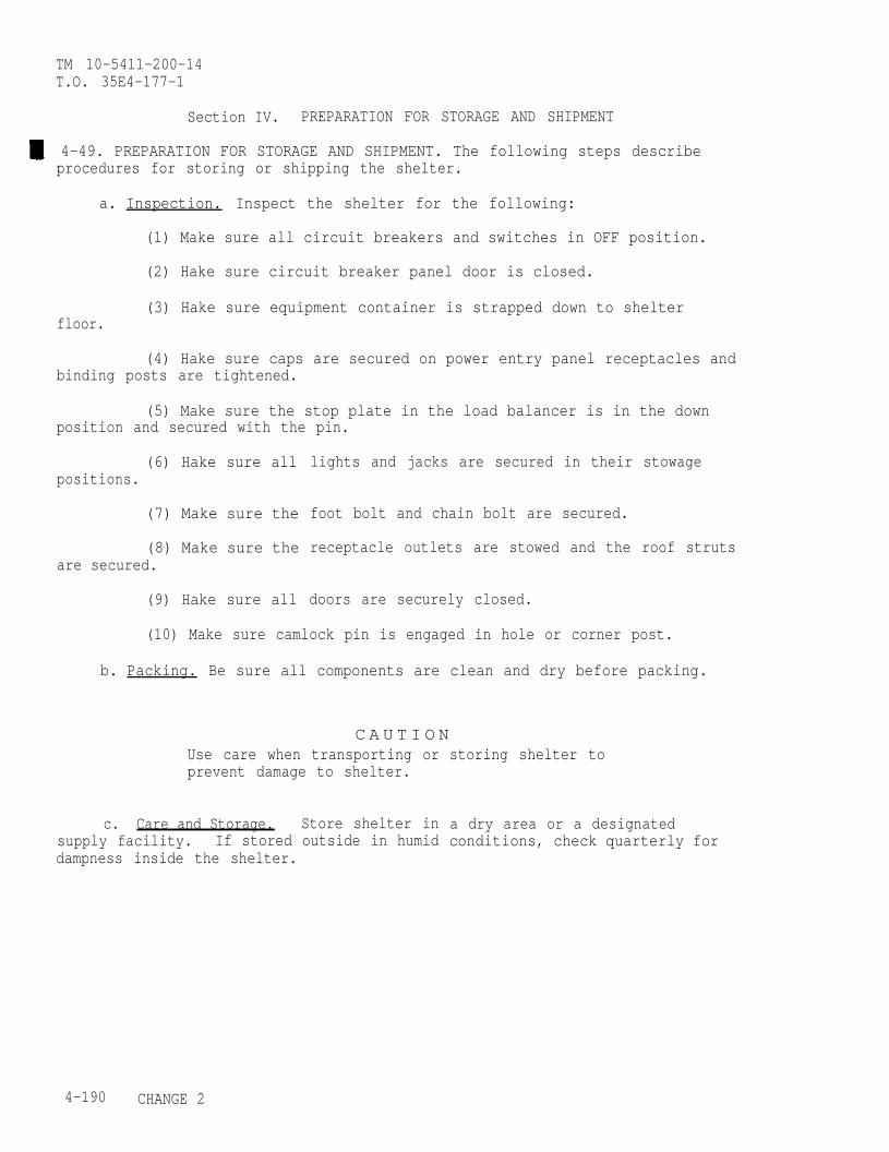
TM 10-5411-200-14T.O. 35E4-177-1
Section IV. PREPARATION FOR STORAGE AND SHIPMENT
4-49. PREPARATION FOR STORAGE AND SHIPMENT. The following steps describeprocedures for storing or shipping the shelter.
a. Inspection. Inspect the shelter for the following:
(1) Make sure all circuit breakers and switches in OFF position.
(2) Hake sure circuit breaker panel door is closed.
(3) Hake sure equipment container is strapped down to shelterfloor.
(4) Hake sure caps are secured on power entry panel receptacles andbinding posts are tightened.
(5) Make sure the stop plate in the load balancer is in the downposition and secured with the pin.
(6) Hake sure allpositions.
(7) Make sure the
(8) Make sure theare secured.
(9) Hake sure all
lights and jacks are secured in their stowage
foot bolt and chain bolt are secured.
receptacle outlets are stowed and the roof struts
doors are securely closed.
(10) Make sure camlock pin is engaged in hole or corner post.
b. Packing. Be sure all components are clean and dry before packing.
C A U T I O NUse care when transporting orprevent damage to shelter.
c. Care and Storage. Store shelter insupply facility. If stored outside in humiddampness inside the shelter.
storing shelter to
a dry area or a designatedconditions, check quarterly for
4-190 CHANGE 2
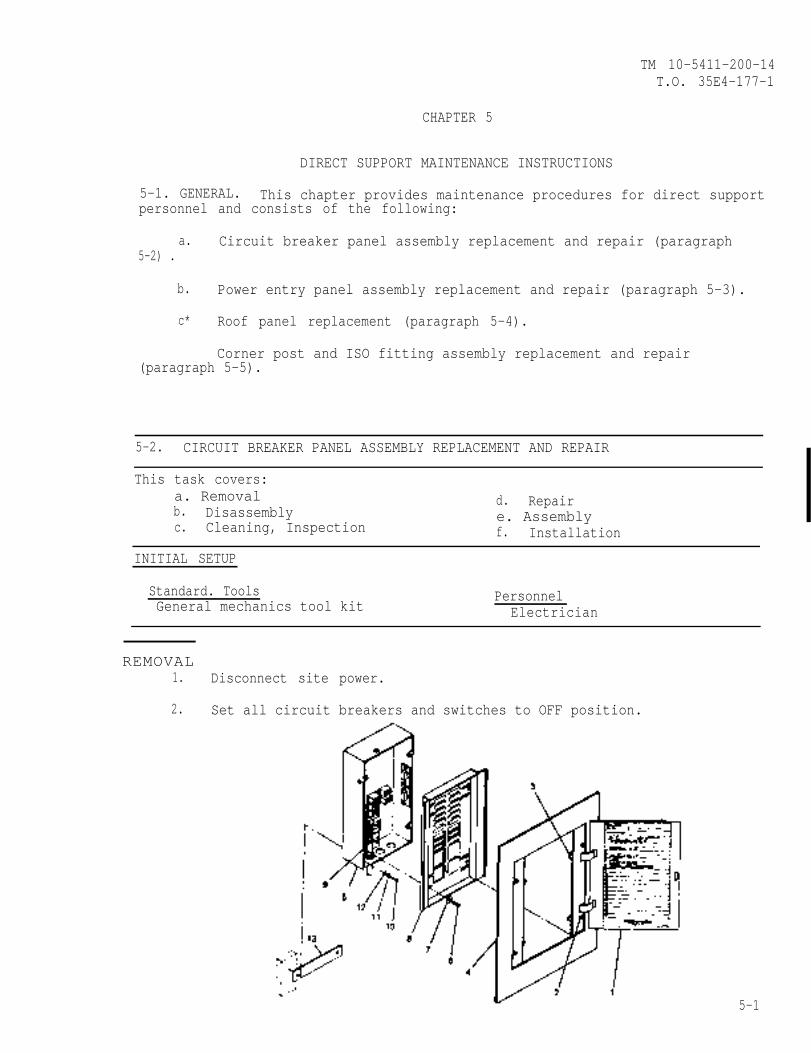
TM 10-5411-200-14T.O. 35E4-177-1
CHAPTER 5
DIRECT SUPPORT MAINTENANCE INSTRUCTIONS
5-1. GENERAL. This chapter provides maintenance procedures for direct supportpersonnel and consists of the following:
a. Circuit breaker panel assembly replacement and repair (paragraph5-2) .
b. Power entry panel assembly replacement and repair (paragraph 5-3).
c* Roof panel replacement (paragraph 5-4).
Corner post and ISO fitting assembly replacement and repair(paragraph 5-5).
5-2. CIRCUIT BREAKER PANEL ASSEMBLY REPLACEMENT AND REPAIR
This task covers:a. Removal d. Repairb. Disassembly e. Assemblyc. Cleaning, Inspection f. Installation
INITIAL SETUP
Standard. Tools PersonnelGeneral mechanics tool kit Electrician
REMOVAL1. Disconnect site power.
2. Set all circuit breakers and switches to OFF position.
5-1
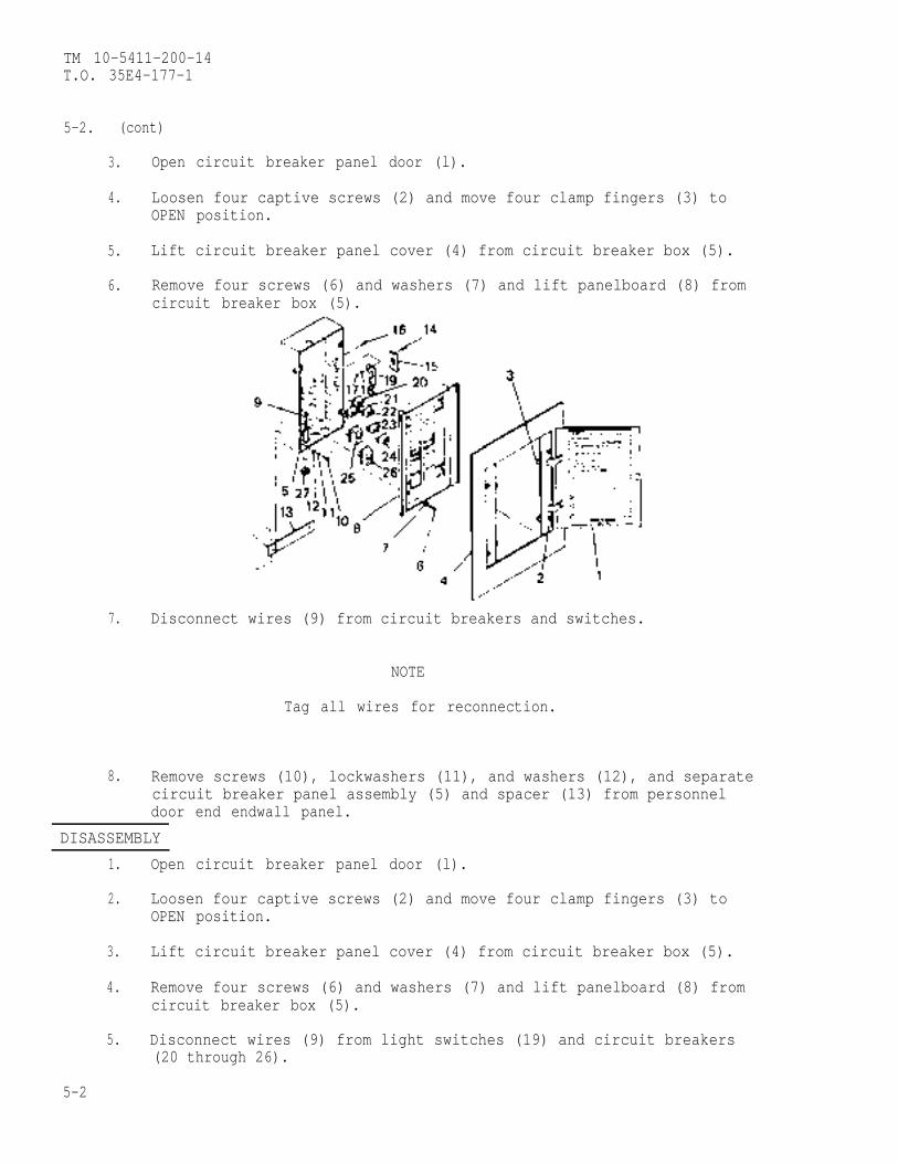
TM 10-5411-200-14T.O. 35E4-177-1
5-2. (cont)
3. Open circuit breaker panel door (l).
4. Loosen four captive screws (2) and move four clamp fingers (3) toOPEN position.
5. Lift circuit breaker panel cover (4) from circuit breaker box (5).
6. Remove four screws (6) and washers (7) and lift panelboard (8) fromcircuit breaker box (5).
7. Disconnect wires (9) from circuit breakers and switches.
NOTE
Tag all wires for reconnection.
8. Remove screws (10), lockwashers (11), and washers (12), and separatecircuit breaker panel assembly (5) and spacer (13) from personneldoor end endwall panel.
DISASSEMBLY
1. Open circuit breaker panel door (l).
2. Loosen four captive screws (2) and move four clamp fingers (3) toOPEN position.
3. Lift circuit breaker panel cover (4) from circuit breaker box (5).
4. Remove four screws (6) and washers (7) and lift panelboard (8) fromcircuit breaker box (5).
5. Disconnect wires (9) from light switches (19) and circuit breakers(20 through 26).
5-2
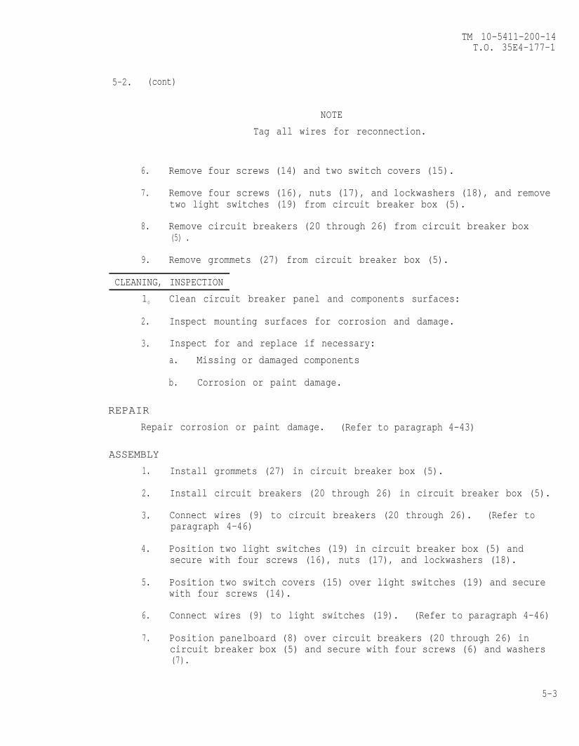
TM 10-5411-200-14T.O. 35E4-177-1
5-2. (cont)
NOTE
Tag all wires for reconnection.
6. Remove four screws (14) and two switch covers (15).
7. Remove four screws (16), nuts (17), and lockwashers (18), and removetwo light switches (19) from circuit breaker box (5).
8. Remove circuit breakers (20 through 26) from circuit breaker box(5) .
9. Remove grommets (27) from circuit breaker box (5).
CLEANING, INSPECTION
10 Clean circuit breaker panel and components surfaces:
2. Inspect mounting surfaces for corrosion and damage.
3. Inspect for and replace if necessary:
a. Missing or damaged components
b. Corrosion or paint damage.
REPAIR
Repair corrosion or paint damage. (Refer to paragraph 4-43)
ASSEMBLY
1.
2.
3.
4.
5.
6.
7.
Install grommets (27) in circuit breaker box (5).
Install circuit breakers (20 through 26) in circuit breaker box (5).
Connect wires (9) to circuit breakers (20 through 26). (Refer toparagraph 4-46)
Position two light switches (19) in circuit breaker box (5) andsecure with four screws (16), nuts (17), and lockwashers (18).
Position two switch covers (15) over light switches (19) and securewith four screws (14).
Connect wires (9) to light switches (19). (Refer to paragraph 4-46)
Position panelboard (8) over circuit breakers (20 through 26) incircuit breaker box (5) and secure with four screws (6) and washers(7).
5-3
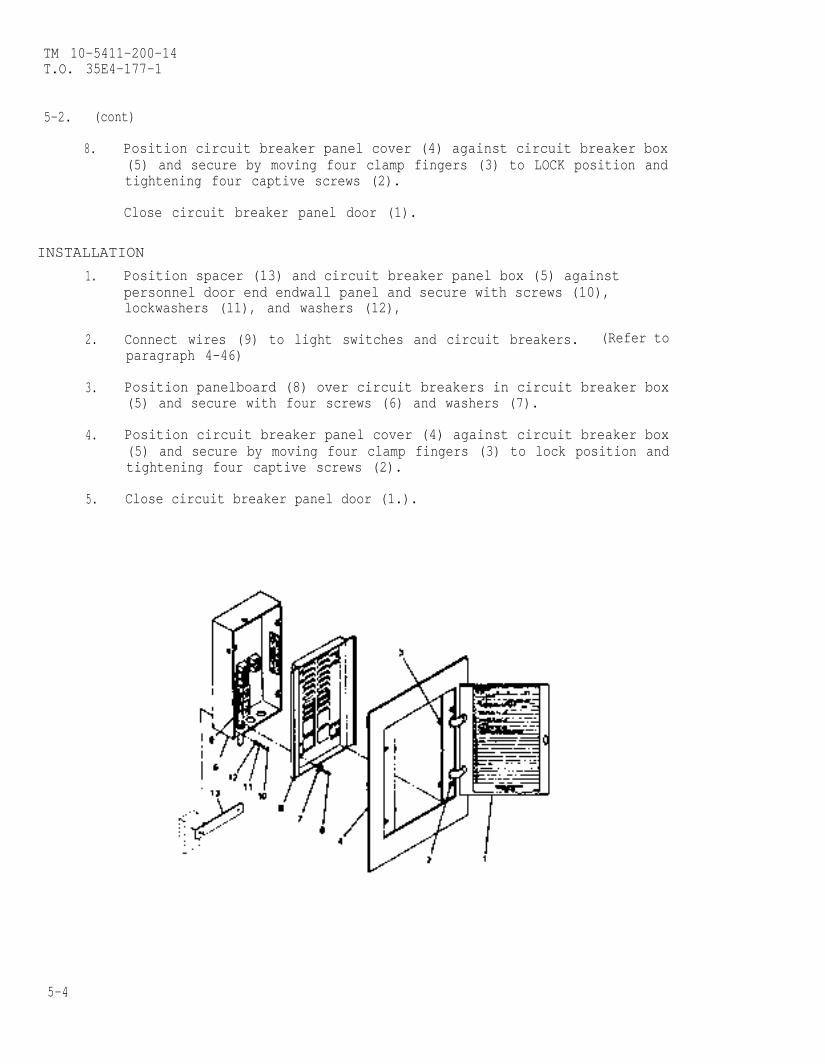
TM 10-5411-200-14T.O. 35E4-177-1
5-2. (cont)
8. Position circuit breaker panel cover (4) against circuit breaker box(5) and secure by moving four clamp fingers (3) to LOCK position andtightening four captive screws (2).
Close circuit breaker panel door (1).
INSTALLATION
1. Position spacer (13) and circuit breaker panel box (5) againstpersonnel door end endwall panel and secure with screws (10),lockwashers (11), and washers (12),
2. Connect wires (9) to light switches and circuit breakers. (Refer toparagraph 4-46)
3. Position panelboard (8) over circuit breakers in circuit breaker box(5) and secure with four screws (6) and washers (7).
4. Position circuit breaker panel cover (4) against circuit breaker box(5) and secure by moving four clamp fingers (3) to lock position andtightening four captive screws (2).
5. Close circuit breaker panel door (1.).
5-4

TM 10-5411-200-14T.O. 35E4-177-1
5-3. POWER ENTRY PANEL ASSEMBLY REPLACEMENT AND REPAIR
This task covers:a. Removal d. Repairb. Disassembly e. Assemblyc. Cleaning, Inspection f. Installation
INITIAL SETUP
Special Tools Standard ToolsHand blind riveter, Appendix B, Item 2 General mechanics tool kitCrimping took, Appendix B, Item 12 Personnel
Electrician
W A R N I N GDisconnect all power sources from power entry panelassembly before removing.
REMOVAL
1. Inside shelter, remove screws (l),lockwashers (2), and washers (3),and carefully lift cover assembly(4) away from personnel door endendwall panel as far as it will go,
2. Disconnect wires at receptacles andterminals/connectors from back ofpower entry panel assembly (5).
NOTE
Tag all wires for reconnection.
3. Outside shelter, drill out rivets(6) and remove power entry panelassembly (5) from personnel doorend endwall panel. (Refer toparagraph 4-32)
CHANGE 2 5-5
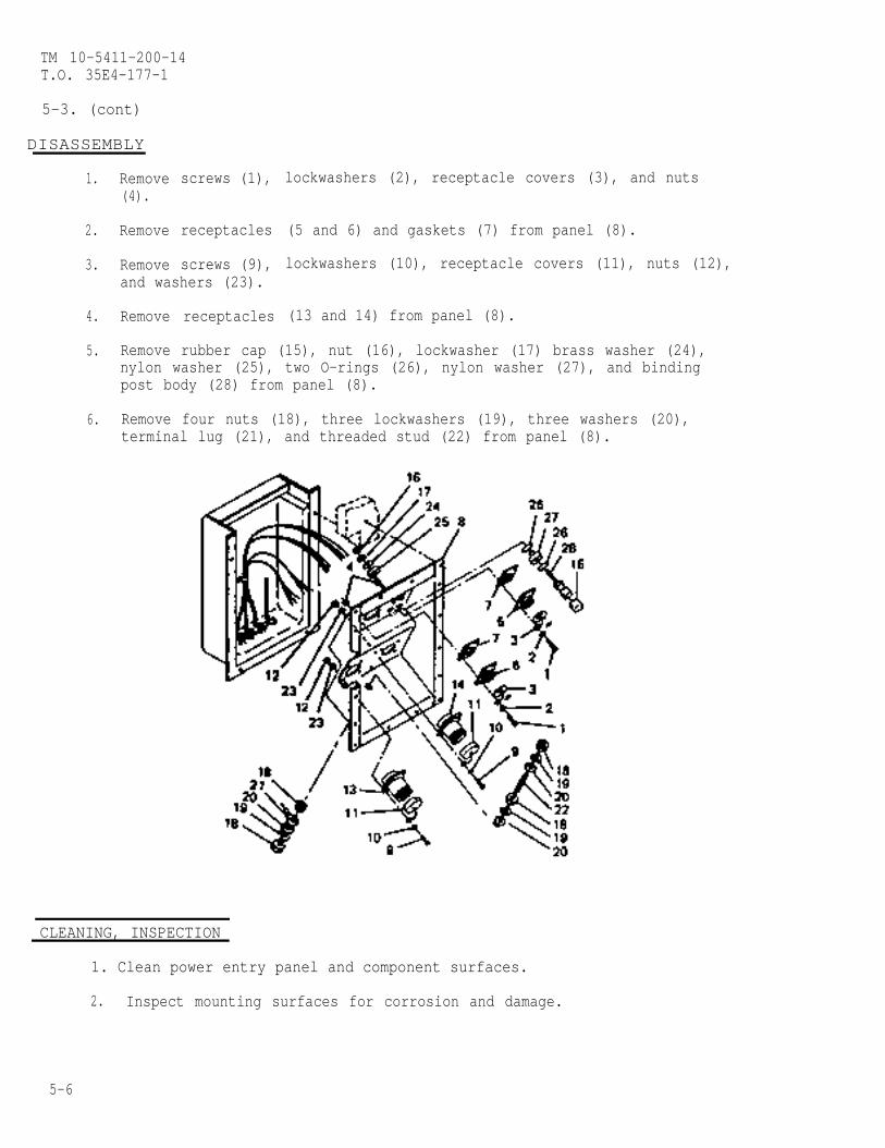
TM 10-5411-200-14T.O. 35E4-177-1
5-3. (cont)
DISASSEMBLY
1.
2.
3.
4.
5.
6.
Remove(4).
Remove
Remove
screws (1),
receptacles
screws (9),and washers (23).
Remove receptacles
lockwashers (2), receptacle covers (3), and nuts
(5 and 6) and gaskets (7) from panel (8).
lockwashers (10), receptacle covers (11), nuts (12),
(13 and 14) from panel (8).
Remove rubber cap (15), nut (16), lockwasher (17) brass washer (24),nylon washer (25), two O-rings (26), nylon washer (27), and bindingpost body (28) from panel (8).
Remove four nuts (18), three lockwashers (19), three washers (20),terminal lug (21), and threaded stud (22) from panel (8).
CLEANING, INSPECTION
1. Clean power entry panel and component surfaces.
2. Inspect mounting surfaces for corrosion and damage.
5-6
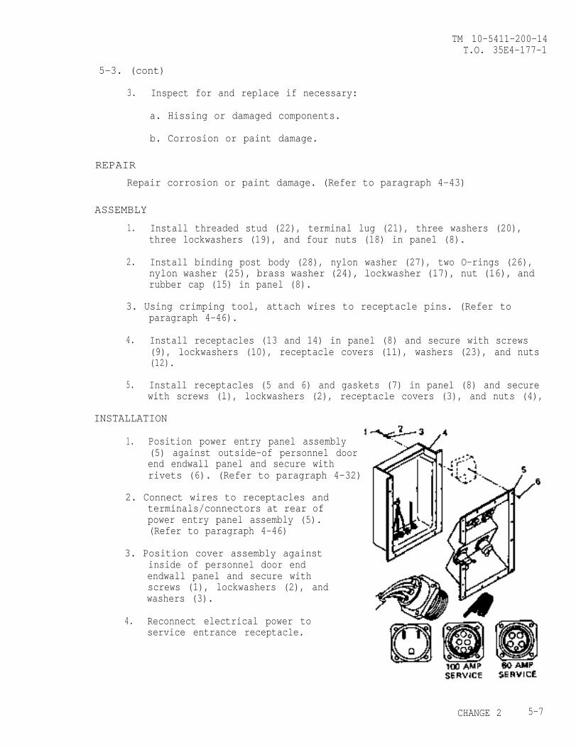
TM 10-5411-200-14T.O. 35E4-177-1
5-3. (cont)
3. Inspect for and replace if necessary:
a. Hissing or damaged components.
b. Corrosion or paint damage.
REPAIR
Repair corrosion or paint damage. (Refer to paragraph 4-43)
ASSEMBLY
1. Install threaded stud (22), terminal lug (21), three washers (20),three lockwashers (19), and four nuts (18) in panel (8).
2. Install binding post body (28), nylon washer (27), two O-rings (26),nylon washer (25), brass washer (24), lockwasher (17), nut (16), andrubber cap (15) in panel (8).
3. Using crimping tool, attach wires to receptacle pins. (Refer toparagraph 4-46).
4. Install receptacles (13 and 14) in panel (8) and secure with screws(9), lockwashers (10), receptacle covers (11), washers (23), and nuts(12).
5. Install receptacles (5 and 6) and gaskets (7) in panel (8) and securewith screws (l), lockwashers (2), receptacle covers (3), and nuts (4),
INSTALLATION
1. Position power entry panel assembly(5) against outside-of personnel doorend endwall panel and secure withrivets (6). (Refer to paragraph 4-32)
2. Connect wires to receptacles andterminals/connectors at rear ofpower entry panel assembly (5).(Refer to paragraph 4-46)
3. Position cover assembly againstinside of personnel door endendwall panel and secure withscrews (1), lockwashers (2), and
4.
washers (3).
Reconnect electrical power toservice entrance receptacle.
CHANGE 2 5-7
TM 10-5411-200-14T.O. 35E4-177-1
5-4. ROOF PANEL REPLACEMENT
This task coversa.b. Installation
INITIAL SETUP
Special Tools Personnel - 6Top lifting container lift sling, 1 ElectricianAppendix D
Standard Tools Sealing compound, Item 19,General mechanics tool kit Appendix E
Solvent, Item 20, Appendix E
Materials
REMOVAL
1.
2.
3.
4.
5.
6.
7.
8.
9.
Disconnect site power.
Remove receptacle outlets. (Refer to paragraph 4-13)
Set main circuit breaker and circuit breaker CB6 to off position.
Remove hinged roof. (Refer to paragraph 4-20)
Remove fixed roof area ceiling lights. (Refer to paragraph 4-12)
Disconnect and remove all wires from fixed roof beam. Tag all wiresfor reconnection. (Refer to paragraph 4-16)
Remove bolts (1), lockwashers (2), and washers (3) securinq fixed roofto upper ISO fittings (4).
.
Remove bolts (5), lockwashers (6), and washers (7) securing fixed roofto fixed personnel endwall and sidewall.
Remove bolts (8), lockwashers (9), washers (10) and drip cap (11)securing fixed roof to fixed cargo endwall.
W A R N I N G
Methylethylketone is flammable and toxic and shallbe used in swell-ventilated area away from sparksor open flame. Gloves should be worn during use.
5-8
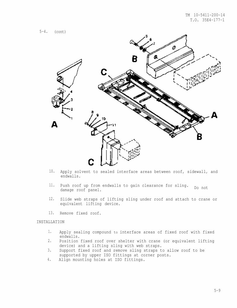
TM 10-5411-200-14T.O. 35E4-177-1
5-4. (cont)
10. Apply solvent to sealed interface areas between roof, sidewall, andendwalls.
11. Push roof up from endwalls to gain clearance for sling. Do notdamage roof panel.
12. Slide web straps of lifting sling under roof and attach to crane orequivalent lifting device.
13. Remove fixed roof.
INSTALLATION
1. Apply sealing compound to interface areas of fixed roof with fixedendwalls.
2. Position fixed roof over shelter with crane (or equivalent liftingdevice) and a lifting sling with web straps.
3. Support fixed roof and remove sling straps to allow roof to besupported by upper ISO fittings at corner posts.
4. Align mounting holes at ISO fittings.
5-9
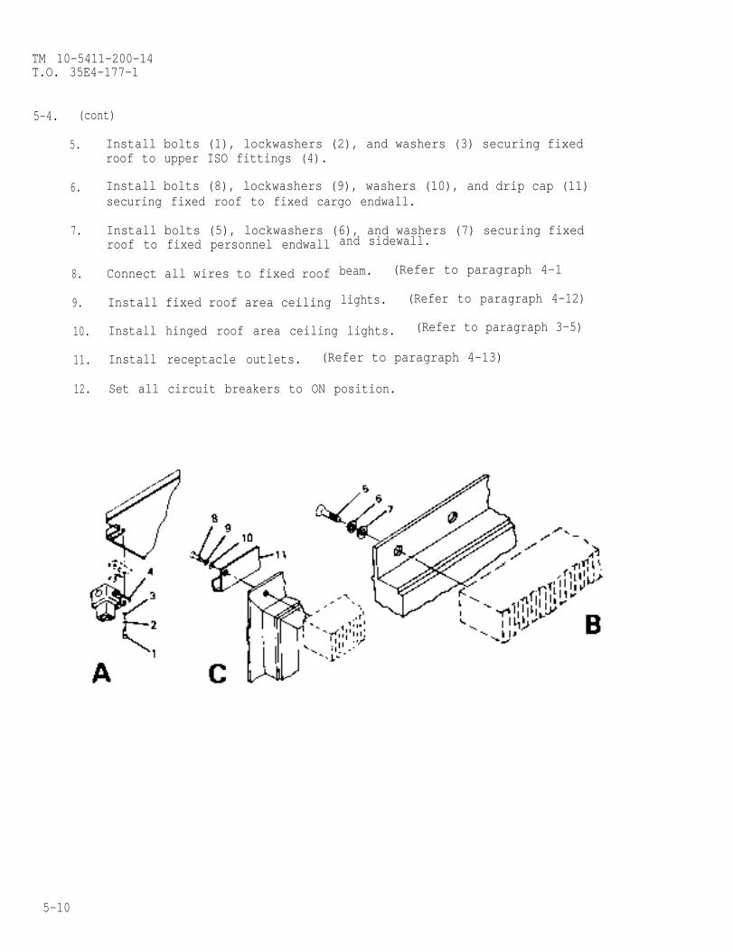
TM 10-5411-200-14T.O. 35E4-177-1
5-4. (cont)
5. Install bolts (1), lockwashers (2), and washers (3) securing fixedroof to upper ISO fittings (4).
6. Install bolts (8), lockwashers (9), washers (10), and drip cap (11)securing fixed roof to fixed cargo endwall.
7. Install bolts (5), lockwashers (6), and washers (7) securing fixedroof to fixed personnel endwall
8. Connect all wires to fixed roof
9. Install fixed roof area ceiling
and sidewall.
beam. (Refer to paragraph 4-1
lights. (Refer to paragraph 4-12)
10. Install hinged roof area ceiling lights. (Refer to paragraph 3-5)
11. Install receptacle outlets. (Refer to paragraph 4-13)
12. Set all circuit breakers to ON position.
5-10
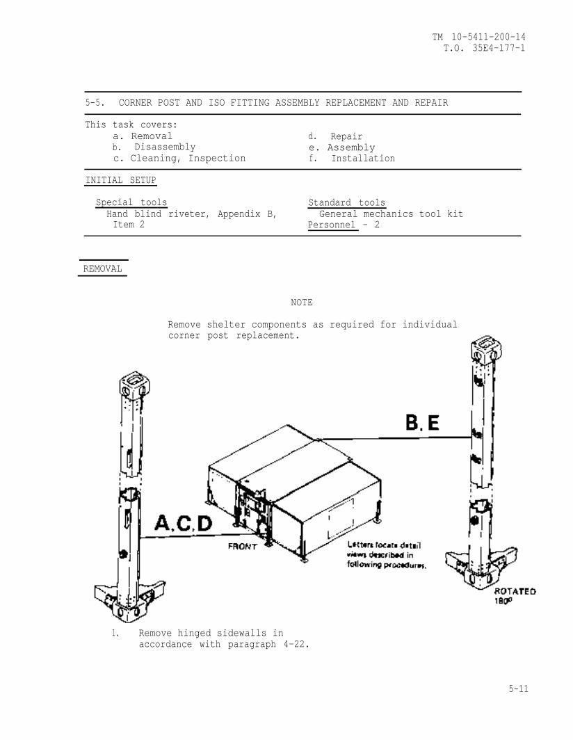
TM 10-5411-200-14T.O. 35E4-177-1
5-5. CORNER POST AND ISO FITTING ASSEMBLY REPLACEMENT AND REPAIR
This task covers:a. Removal d. Repairb. Disassembly e. Assemblyc. Cleaning, Inspection f. Installation
INITIAL SETUP
Special tools Standard toolsHand blind riveter, Appendix B, General mechanics tool kitItem 2 Personnel - 2
REMOVAL
NOTE
Remove shelter components as required for individualcorner post replacement.
1. Remove hinged sidewalls inaccordance with paragraph 4-22.
5-11
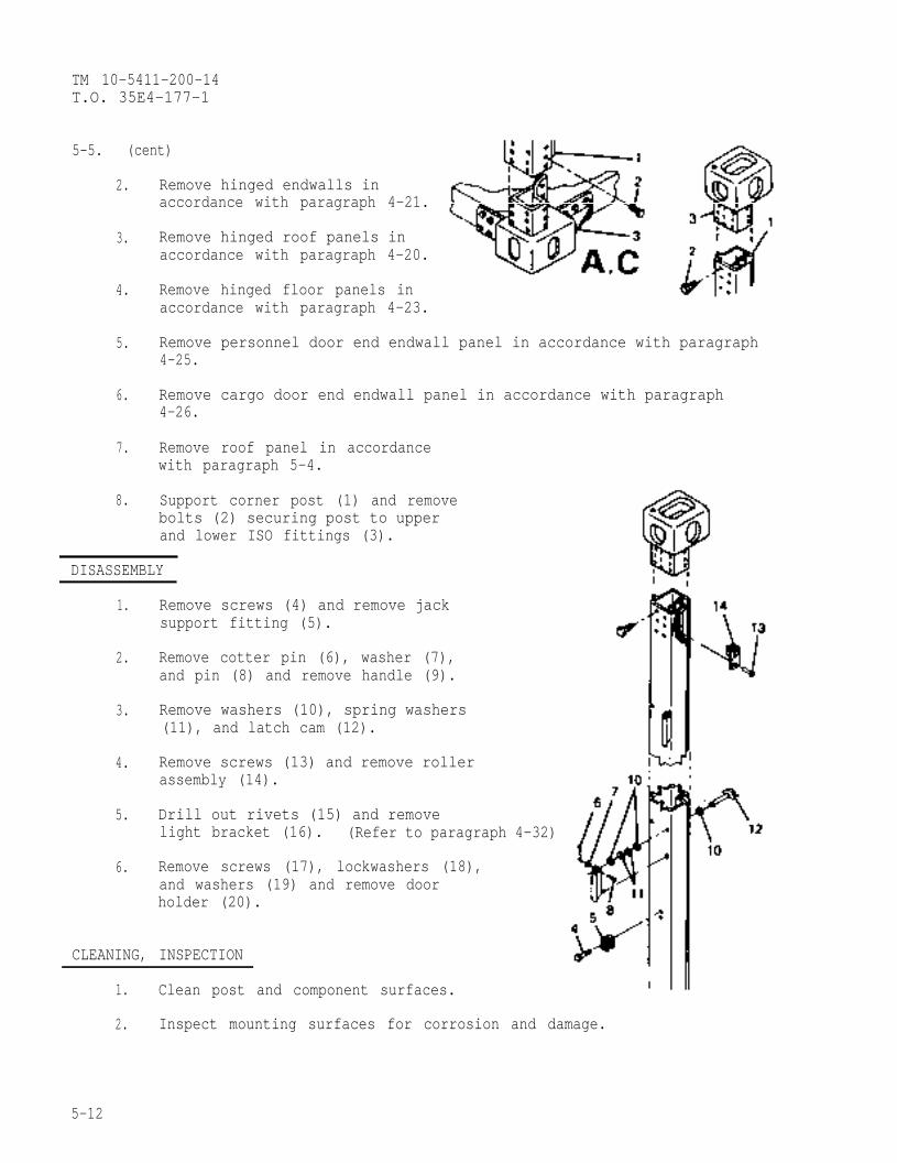
TM 10-5411-200-14T.O. 35E4-177-1
5-5. (cent)
2. Remove hinged endwalls inaccordance with paragraph 4-21.
3. Remove hinged roof panels inaccordance with paragraph 4-20.
4. Remove hinged floor panels in
5.
6.
7.
8.
accordance with paragraph 4-23.
Remove personnel door end endwall panel in accordance with paragraph4-25.
Remove cargo door end endwall panel in accordance with paragraph4-26.
Remove roof panel in accordancewith paragraph 5-4.
Support corner post (1) and removebolts (2) securing post to upperand lower ISO fittings (3).
DISASSEMBLY
1.
2.
3.
4.
5.
6.
Remove screws (4) and remove jacksupport fitting (5).
Remove cotter pin (6), washer (7),and pin (8) and remove handle (9).
Remove washers (10), spring washers(11), and latch cam (12).
Remove screws (13) and remove rollerassembly (14).
Drill out rivets (15) and removelight bracket (16). (Refer to paragraph 4-32)
Remove screws (17), lockwashers (18),and washers (19) and remove doorholder (20).
CLEANING, INSPECTION
1. Clean post and component surfaces.
2. Inspect mounting surfaces for corrosion and damage.
5-12
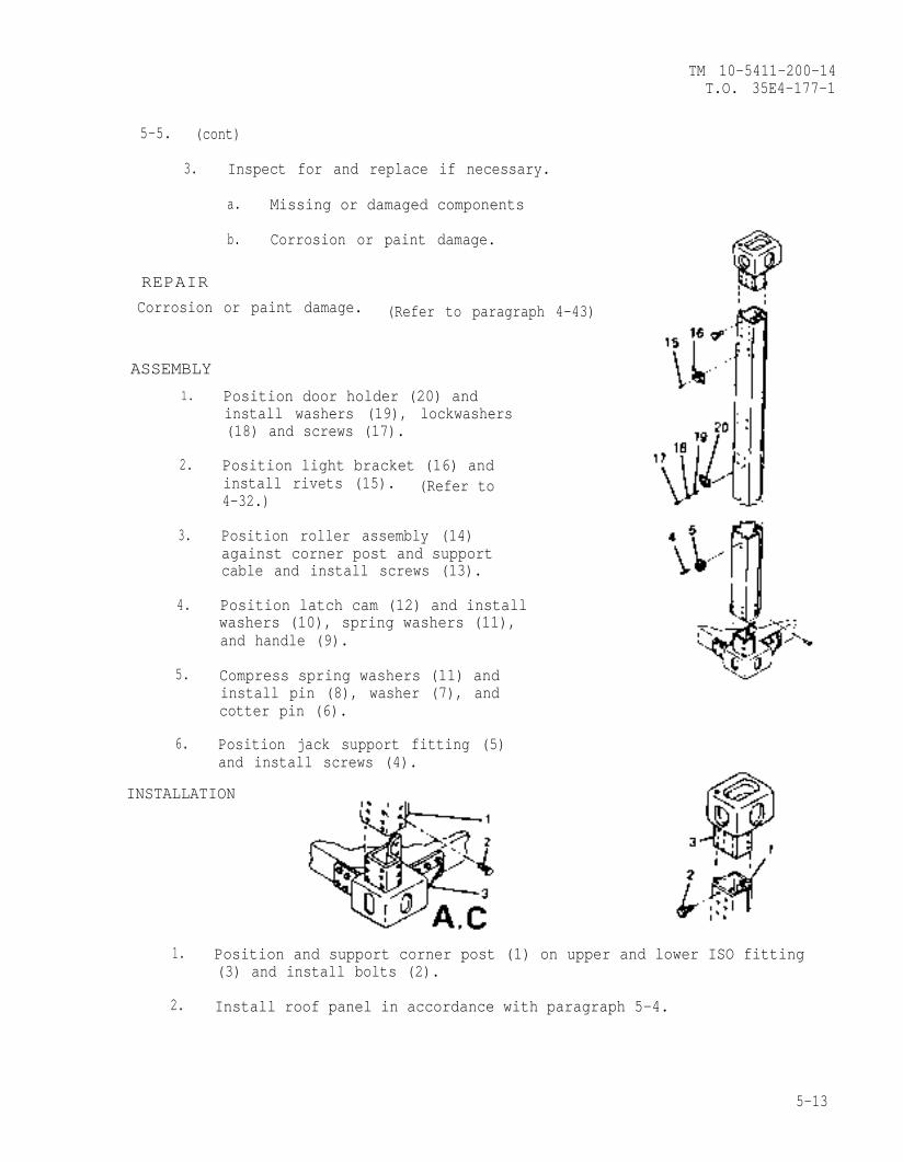
TM 10-5411-200-14T.O. 35E4-177-1
5-5. (cont)
3. Inspect for and replace if necessary.
a. Missing or damaged components
b. Corrosion or paint damage.
REPAIR
Corrosion or paint damage. (Refer to paragraph 4-43)
ASSEMBLY
1.
2.
3.
4.
5.
6.
Position door holder (20) andinstall washers (19), lockwashers(18) and screws (17).
Position light bracket (16) andinstall rivets (15). (Refer to4-32.)
Position roller assembly (14)against corner post and supportcable and install screws (13).
Position latch cam (12) and installwashers (10), spring washers (11),and handle (9).
Compress spring washers (11) andinstall pin (8), washer (7), andcotter pin (6).
Position jack support fitting (5)and install screws (4).
INSTALLATION
1. Position and support corner post (1) on upper and lower ISO fitting(3) and install bolts (2).
2. Install roof panel in accordance with paragraph 5-4.
5-13

TM 10-5411-200-14T.O. 35E4-177-1
5-5. (con)
3. Install cargo door end endwall panel in accordance with paragraph 4-26.
4. Install personnel door end endwall panel in accordance withparagraph 4-25.
5. Install hinged floor panels in accordance with paragraph 4-23.
6. Install hinged roof panels in accordance with paragraph 4-20.
7. Install hinged endwalls in accordance with paragraph 4-21.
8 . Remove hinged sidewalls in accordance with paragraph 4-22.
5-14
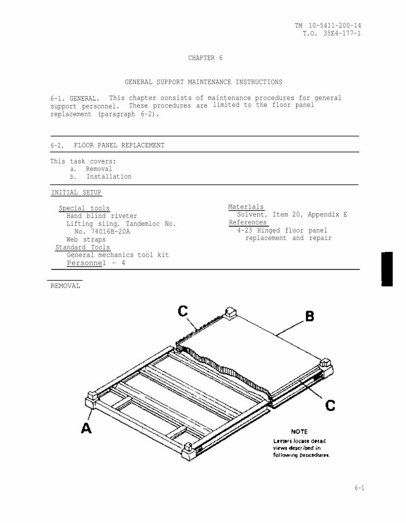
TM 10-5411-200-14T.O. 35E4-177-1
CHAPTER 6
GENERAL SUPPORT MAINTENANCE INSTRUCTIONS
6-1. GENERAL. This chapter consists of maintenance procedures for generalsupport personnel. These procedures are limited to the floor panelreplacement (paragraph 6-2).
6-2. FLOOR PANEL REPLACEMENT
This task covers:a. Removalb. Installation
INITIAL SETUP
Special tools MaterialsHand blind riveter Solvent, Item 20, Appendix ELifting sling, Tandemloc No. References
No. 74016B-20A 4-23 Hinged floor panelWeb straps replacement and repair
Standard ToolsGeneral mechanics tool kitPersonnel - 4
REMOVAL
6-1
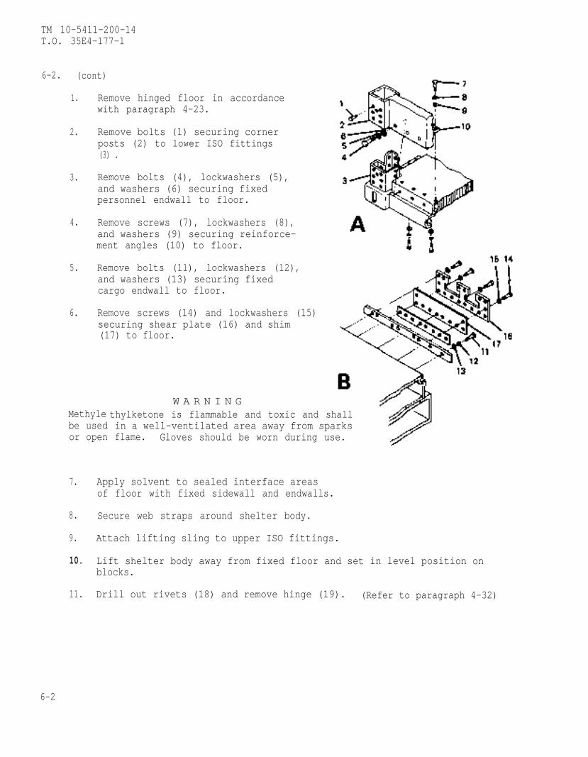
TM 10-5411-200-14T.O. 35E4-177-1
6-2. (cont)
1.
2.
3.
4.
5.
6.
Remove hinged floor in accordancewith paragraph 4-23.
Remove bolts (1) securing cornerposts (2) to lower ISO fittings(3) .
Remove bolts (4), lockwashers (5),and washers (6) securing fixedpersonnel endwall to floor.
Remove screws (7), lockwashers (8),and washers (9) securing reinforce-ment angles (10) to floor.
Remove bolts (11), lockwashers (12),and washers (13) securing fixedcargo endwall to floor.
Remove screws (14) and lockwashers (15)securing shear plate (16) and shim(17) to floor.
Methylebe usedor open
W A R N I N Gthylketone is flammable and toxic and shallin a well-ventilated area away from sparksflame. Gloves should be worn during use.
7. Apply solvent to sealed interface areasof floor with fixed sidewall and endwalls.
8. Secure web straps around shelter body.
9. Attach lifting sling to upper ISO fittings.
10. Lift shelter body away from fixed floor and set in level position onblocks.
11. Drill out rivets (18) and remove hinge (19). (Refer to paragraph 4-32)
6-2
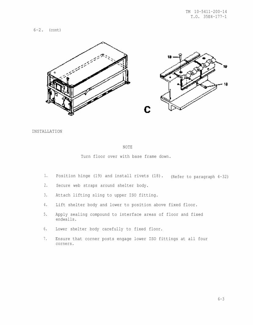
TM 10-5411-200-14T.O. 35E4-177-1
6-2. (cont)
INSTALLATION
NOTE
Turn floor over with base frame down.
1. Position hinge (19) and install rivets (18). (Refer to paragraph 4-32)
2. Secure web straps around shelter body.
3. Attach lifting sling to upper ISO fitting.
4. Lift shelter body and lower to position above fixed floor.
5. Apply sealing compound to interface areas of floor and fixedendwalls.
6. Lower shelter body carefully to fixed floor.
7. Ensure that corner posts engage lower ISO fittings at all fourcorners.
6-3
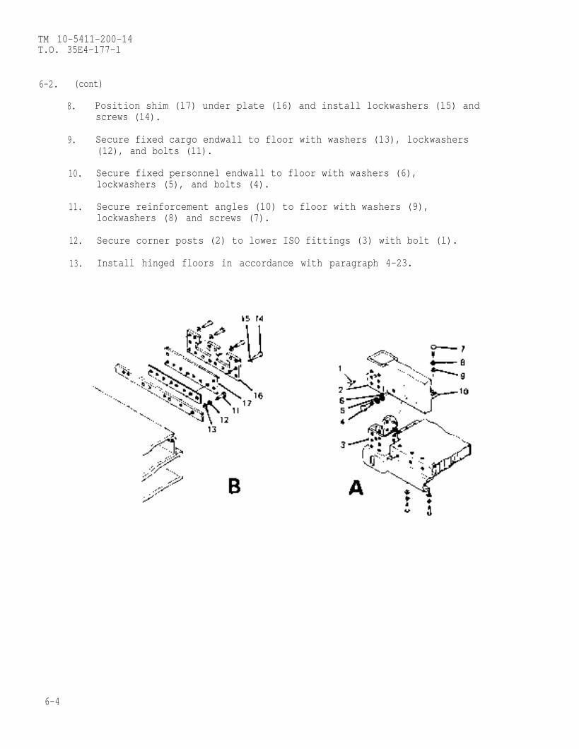
TM 10-5411-200-14T.O. 35E4-177-1
6-2. (cont)
8. Position shim (17) under plate (16) and install lockwashers (15) andscrews (14).
9. Secure fixed cargo endwall to floor with washers (13), lockwashers(12), and bolts (11).
10. Secure fixed personnel endwall to floor with washers (6),lockwashers (5), and bolts (4).
11. Secure reinforcement angles (10) to floor with washers (9),lockwashers (8) and screws (7).
12. Secure corner posts (2) to lower ISO fittings (3) with bolt (l).
13. Install hinged floors in accordance with paragraph 4-23.
6-4
TM 10-5411-200-14T.O. 35E4-177-1
APPENDIX A
REFERENCES
A-1. SCOPE
This appendix lists all forms, field manuals, technical manuals and miscel-laneous publications referenced in this manual.
A-2.
(A)(F)(A)(A)
A-3.
(A)(F)
A-4.
(F)(A)
FORMS
Recommended Changes to Publications on Blank Forms . . . DA-2028Reporting Errors And Improvement . . . . . . . . . . . . AFTO-22Transportation Discrepancy Report . . . . . . . . . . . SF-361Quality Deficiency Report . . . . . . . . . . . . . . . SF-368
FIELD NANUALS
Destruction Of Equipment to Prevent Enemy Use . . . . . TM 750-244-3Inspection Manual . . . . . . . . . . . . . . . . TO 35C2-3
TECHNICAL NANUALS
Repair Parts and Special Tools List . . . . . . . . . . TM 10-5411-200-24PMaintenance Reporting . . . . . . . . . . . . . . . AFM 66-1The Army Maintenance Management System . . . . . . . . . DA Pamphlet 738-750
CHANGE 2 A-1/(A-2 blank)

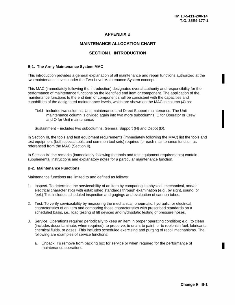
TM 10-5411-200-14 T.O. 35E4-177-1
APPENDIX B
MAINTENANCE ALLOCATION CHART
SECTION I. INTRODUCTION
Change 9 B-1
B-1. The Army Maintenance System MAC This introduction provides a general explanation of all maintenance and repair functions authorized at the two maintenance levels under the Two-Level Maintenance System concept. This MAC (immediately following the introduction) designates overall authority and responsibility for the performance of maintenance functions on the identified end item or component. The application of the maintenance functions to the end item or component shall be consistent with the capacities and capabilities of the designated maintenance levels, which are shown on the MAC in column (4) as:
Field - includes two columns, Unit maintenance and Direct Support maintenance. The Unit maintenance column is divided again into two more subcolumns, C for Operator or Crew and O for Unit maintenance.
Sustainment – includes two subcolumns, General Support (H) and Depot (D).
In Section III, the tools and test equipment requirements (immediately following the MAC) list the tools and test equipment (both special tools and common tool sets) required for each maintenance function as referenced from the MAC (Section II). In Section IV, the remarks (immediately following the tools and test equipment requirements) contain supplemental instructions and explanatory notes for a particular maintenance function. B-2. Maintenance Functions Maintenance functions are limited to and defined as follows: 1. Inspect. To determine the serviceability of an item by comparing its physical, mechanical, and/or
electrical characteristics with established standards through examination (e.g., by sight, sound, or feel.) This includes scheduled inspection and gagings and evaluation of cannon tubes.
2. Test. To verify serviceability by measuring the mechanical, pneumatic, hydraulic, or electrical characteristics of an item and comparing those characteristics with prescribed standards on a scheduled basis, i.e., load testing of lift devices and hydrostatic testing of pressure hoses.
3. Service. Operations required periodically to keep an item in proper operating condition; e.g., to clean (includes decontaminate, when required), to preserve, to drain, to paint, or to replenish fuel, lubricants, chemical fluids, or gases. This includes scheduled exercising and purging of recoil mechanisms. The following are examples of service functions:
a. Unpack. To remove from packing box for service or when required for the performance of
maintenance operations.
TM 10-5411-200-14 T.O. 35E4-177-1
Change 9 B-2
b. Repack. To return item to packing box after service and other maintenance operations.
c. Clean. To rid the item of contamination.
d. Touch up. To spot paint scratched or blistered surfaces.
e. Mark. To restore obliterated identification. 4. Adjust. To maintain or regulate, within prescribed limits, by bringing into proper position, or by setting
the operating characteristics to specified parameters.
5. Align. To adjust specified variable elements of an item to bring about optimum or desired performance
6. Calibrate. To determine and cause corrections to be made or to be adjusted on instruments of test, measuring, and diagnostic equipment used in precision measurement. Consists of comparisons of two instruments, one of which is a certified standard of known accuracy, to detect and adjust any discrepancy in the accuracy of the instrument being compared.
7. Remove/Install. To remove and install the same item when required to perform service or other maintenance functions. Install may be the act of emplacing, seating, or fixing into position a spare, repair part, or module (component or assembly) in a manner to allow the proper functioning of an equipment or system.
8. Paint. To prepare and spray color coats of paint so that the ammunition can be identified and protected. The color indicating primary use is applied, preferably, to the entire exterior surface as the background color of the item. Other markings are to be repainted as original so as to retain proper ammunition identification.
9. Replace. To remove an unserviceable item and install a serviceable counterpart in its place. “Replace” is authorized by the MAC and assigned maintenance level is shown as the third position code of the Source, Maintenance and Recoverability (SMR) code.
10. Repair. The application of maintenance services, including fault location/troubleshooting, removal/installation, disassembly/assembly procedures and maintenance actions to identify troubles and restore serviceability to an item by correcting specific damage, fault, malfunction, or failure in a part, subassembly, module (component or assembly), end item, or system.
TM 10-5411-200-14 T.O. 35E4-177-1
Change 9 B-3
11. Overhaul. That maintenance effort (service/action) prescribed to restore an item to a completely
serviceable/operational condition as required by maintenance standards in appropriate technical publications. Overhaul is normally the highest degree of maintenance performed by the Army. Overhaul does not normally return an item to like new condition.
12. Rebuild. Consists of those services/actions necessary for the restoration of unserviceable equipment to a like new condition in accordance with original manufacturing standards. Rebuild is the highest degree of material maintenance applied to Army equipment. The rebuild operation includes the act of returning to zero those age measurements (e.g., hours/miles) considered in classifying Army equipment/components.
B-3. Explanation of Columns in the MAC, Section II. Column (1) Group Number. Column (1) lists Functional Group Code (FGC) numbers, the purpose of which is to identify maintenance significant components, assemblies, subassemblies, and modules with the Next Higher Assembly (NHA). Column (2) Component/Assembly. Column (2) contains the names of components, assemblies, subassemblies, and modules for which maintenance is authorized. Column (3) Maintenance Function. Column (3) lists the functions to be performed on the item listed in column (2). (For a detailed explanation of these functions refer to “Maintenance Functions” outlined above).
NOTE The following definitions are applicable to the “repair” maintenance function: Services. Inspect, test, service, adjust, align, calibrate, and/or replace. Fault location/troubleshooting. The process of investigating and detecting the cause of equipment malfunctioning; the act of isolating a fault within a system or Unit Under Test (UUT). Disassembly/assembly. The step-by-step breakdown (taking apart) of a spare/functional group coded item to the level of its least component, that is assigned an SMR code for the level of maintenance under consideration (i.e., identified as maintenance significant). Actions. Welding, grinding, riveting, straightening, facing, machining, and/or resurfacing.
TM 10-5411-200-14 T.O. 35E4-177-1
Change 9 B-4
Column (4) Maintenance Level. Column (4) specifies each level of maintenance authorized to perform each function listed in column (3), by indicating work time required (expressed as manhours in whole hours or decimals) in the appropriate subcolumn. This work time figure represents the active time required to perform that maintenance function at the indicated level of maintenance. If the number or complexity of the tasks within the listed maintenance function varies at different maintenance levels, appropriate work time figures are to be shown for each level. The work time figure represents the average time required to restore an item (assembly, subassembly, component, module, end item, or system) to a serviceable condition under typical field operating conditions. This time includes preparation time (including any necessary disassembly/assembly time), troubleshooting/fault location time, and quality assurance time in addition to the time required to perform the specific tasks identified for the maintenance functions authorized in the MAC. The system designations for the various maintenance levels are as follows: Field:
Sustainment:
NOTE The “L” maintenance level is not included in column (4) of the MAC. Functions to this level of maintenance are identified by work time figure in the “H” column of column (4), and an associated reference code is used in the REMARKS column (6). This code is keyed to the remarks and the SRA complete repair application is explained there.
Column (5) Tools and Equipment Reference Code. Column (5) specifies, by code, those common tool sets (not individual tools), common Test, Measurement and Diagnostic Equipment (TMDE), and special tools, special TMDE and special support equipment required to perform the designated function. Codes are keyed to the entries in the tools and test equipment table. Column (6) Remarks Code. When applicable, this column contains a letter code, in alphabetic order, which is keyed to the remarks table entries. B-4. Explanation of Columns in the Tools and Test Equipment Requirements, Section III. Column (1) - Tool or Test Equipment Reference Code. The tool or test equipment reference code correlates with a code used in column (5) of the MAC. Column (2) - Maintenance Level. The lowest level of maintenance authorized to use the tool or test equipment.
C Operator or crew maintenance O Unit maintenance F Direct Support maintenance
L Specialized Repair Activity H General Support maintenance D Depot maintenance
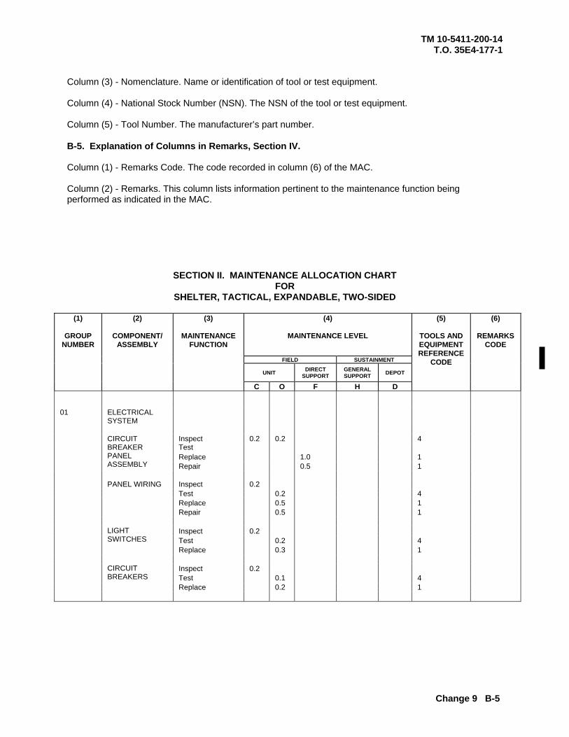
TM 10-5411-200-14 T.O. 35E4-177-1
Change 9 B-5
Column (3) - Nomenclature. Name or identification of tool or test equipment. Column (4) - National Stock Number (NSN). The NSN of the tool or test equipment. Column (5) - Tool Number. The manufacturer’s part number. B-5. Explanation of Columns in Remarks, Section IV. Column (1) - Remarks Code. The code recorded in column (6) of the MAC. Column (2) - Remarks. This column lists information pertinent to the maintenance function being performed as indicated in the MAC.
SECTION II. MAINTENANCE ALLOCATION CHART FOR
SHELTER, TACTICAL, EXPANDABLE, TWO-SIDED
(4)
MAINTENANCE LEVEL FIELD SUSTAINMENT
UNIT DIRECT SUPPORT
GENERAL SUPPORT DEPOT
(1)
GROUP NUMBER
(2)
COMPONENT/ ASSEMBLY
(3)
MAINTENANCE FUNCTION
C O F H D
(5)
TOOLS AND EQUIPMENT REFERENCE
CODE
(6)
REMARKS CODE
01 ELECTRICAL
SYSTEM
Inspect Test
0.2 0.2
4
Replace 1.0 1
CIRCUIT BREAKER PANEL ASSEMBLY Repair 0.5 1
PANEL WIRING Inspect 0.2 Test 0.2 4 Replace 0.5 1 Repair 0.5 1 Inspect 0.2 Test 0.2 4
LIGHT SWITCHES
Replace 0.3 1 Inspect 0.2 Test 0.1 4
CIRCUIT BREAKERS
Replace 0.2 1
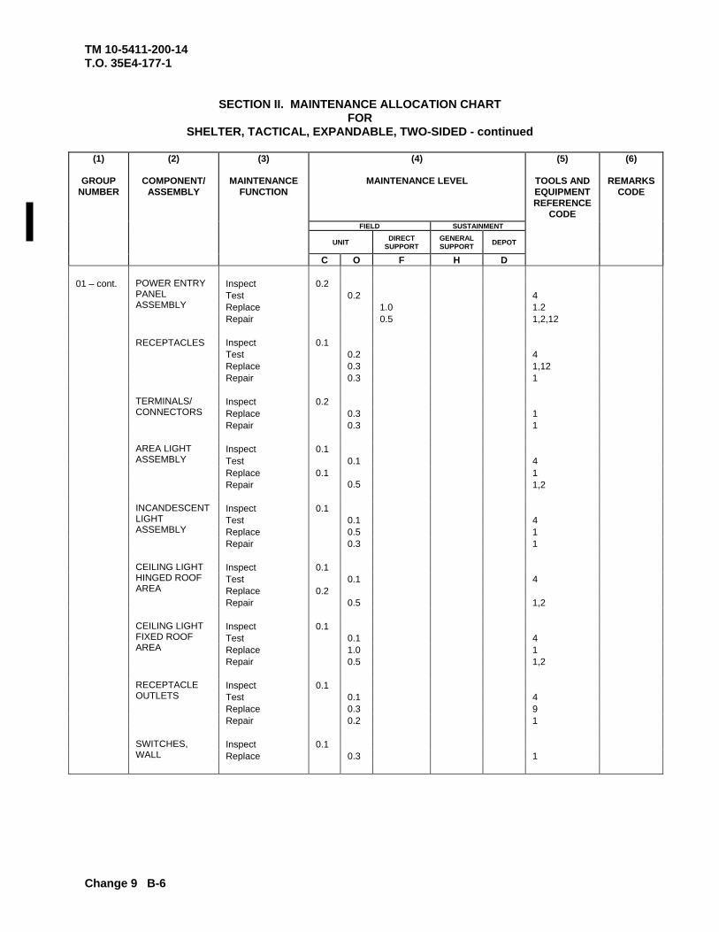
TM 10-5411-200-14 T.O. 35E4-177-1
Change 9 B-6
SECTION II. MAINTENANCE ALLOCATION CHART FOR
SHELTER, TACTICAL, EXPANDABLE, TWO-SIDED - continued
(4)
MAINTENANCE LEVEL
FIELD SUSTAINMENT
UNIT DIRECT SUPPORT
GENERAL SUPPORT DEPOT
(1)
GROUP NUMBER
(2)
COMPONENT/ ASSEMBLY
(3)
MAINTENANCE FUNCTION
C O F H D
(5)
TOOLS AND EQUIPMENT REFERENCE
CODE
(6)
REMARKS CODE
01 – cont. Inspect 0.2 Test 0.2 4 Replace 1.0 1.2
POWER ENTRY PANEL ASSEMBLY
Repair 0.5 1,2,12 RECEPTACLES Inspect 0.1 Test 0.2 4 Replace 0.3 1,12 Repair 0.3 1 Inspect 0.2 Replace 0.3 1 Repair 0.3 1
TERMINALS/ CONNECTORS
Inspect 0.1 Test 0.1 4 Replace 0.1 1
AREA LIGHT ASSEMBLY
Repair 0.5 1,2 Inspect 0.1 Test 0.1 4
INCANDESCENT LIGHT ASSEMBLY Replace 0.5 1
Repair 0.3 1 Inspect 0.1 Test 0.1 4 Replace 0.2
CEILING LIGHT HINGED ROOF AREA
Repair 0.5 1,2 Inspect 0.1 Test 0.1 4 Replace 1.0 1
CEILING LIGHT FIXED ROOF AREA
Repair 0.5 1,2 Inspect 0.1 Test 0.1 4 Replace 0.3 9
RECEPTACLE OUTLETS
Repair 0.2 1 Inspect 0.1
SWITCHES, WALL Replace 0.3 1
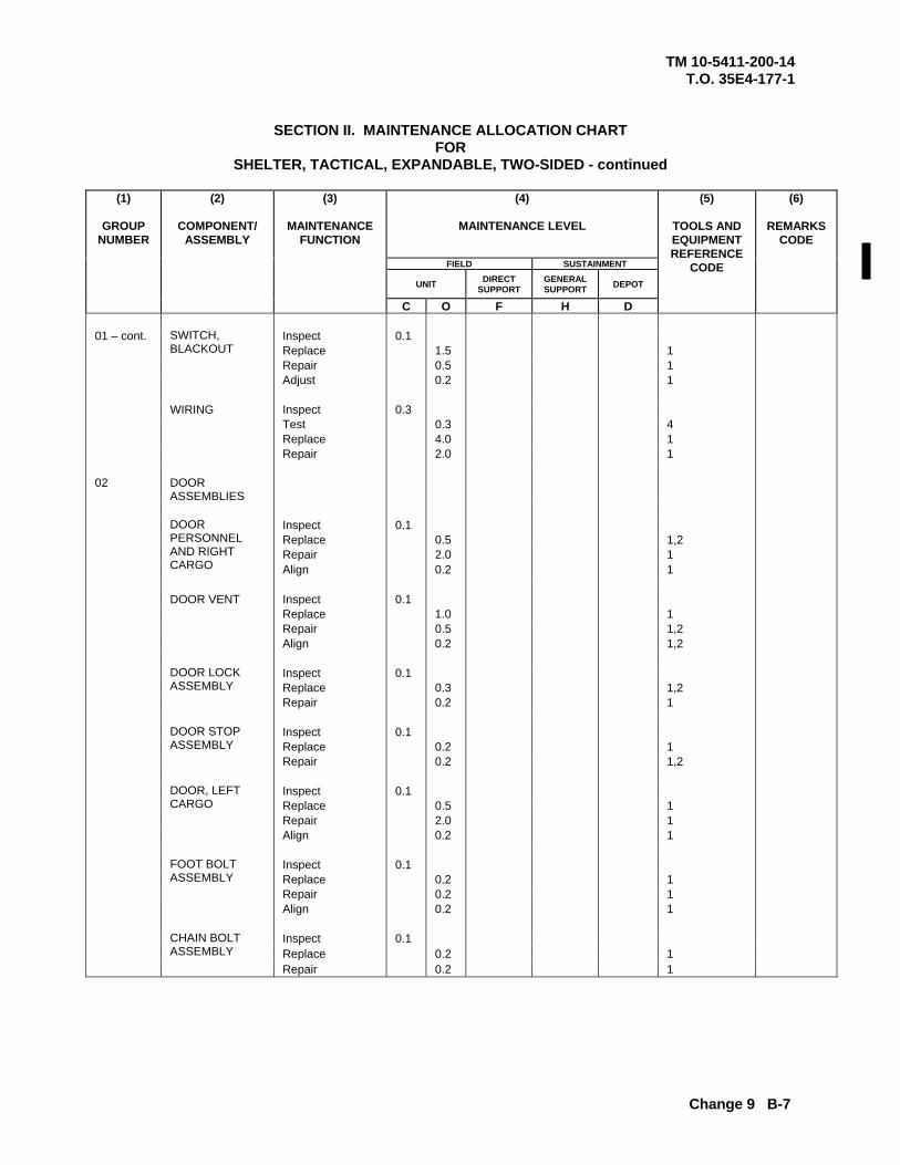
TM 10-5411-200-14 T.O. 35E4-177-1
Change 9 B-7
SECTION II. MAINTENANCE ALLOCATION CHART FOR
SHELTER, TACTICAL, EXPANDABLE, TWO-SIDED - continued
(4)
MAINTENANCE LEVEL FIELD SUSTAINMENT
UNIT DIRECT SUPPORT
GENERAL SUPPORT DEPOT
(1)
GROUP NUMBER
(2)
COMPONENT/ ASSEMBLY
(3)
MAINTENANCE FUNCTION
C O F H D
(5)
TOOLS AND EQUIPMENT REFERENCE
CODE
(6)
REMARKS CODE
01 – cont. Inspect 0.1 Replace 1.5 1 Repair 0.5 1
SWITCH, BLACKOUT
Adjust 0.2 1 WIRING Inspect 0.3 Test 0.3 4 Replace 4.0 1 Repair 2.0 1 02 DOOR
ASSEMBLIES
Inspect 0.1 Replace 0.5 1,2 Repair 2.0 1
DOOR PERSONNEL AND RIGHT CARGO Align 0.2 1
DOOR VENT Inspect 0.1 Replace 1.0 1 Repair 0.5 1,2 Align 0.2 1,2 Inspect 0.1 Replace 0.3 1,2
DOOR LOCK ASSEMBLY
Repair 0.2 1 Inspect 0.1 Replace 0.2 1
DOOR STOP ASSEMBLY
Repair 0.2 1,2 Inspect 0.1 Replace 0.5 1 Repair 2.0 1
DOOR, LEFT CARGO
Align 0.2 1 Inspect 0.1 Replace 0.2 1 Repair 0.2 1
FOOT BOLT ASSEMBLY
Align 0.2 1 Inspect 0.1 Replace 0.2 1
CHAIN BOLT ASSEMBLY
Repair 0.2 1
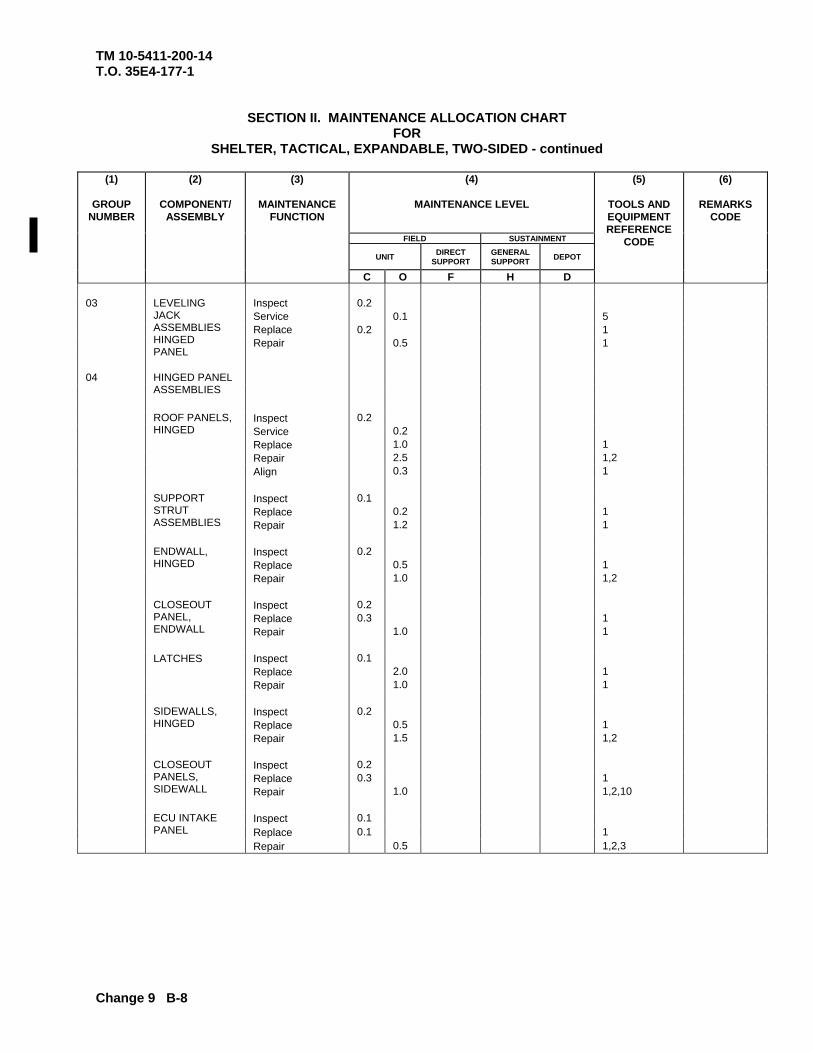
TM 10-5411-200-14 T.O. 35E4-177-1
Change 9 B-8
SECTION II. MAINTENANCE ALLOCATION CHART FOR
SHELTER, TACTICAL, EXPANDABLE, TWO-SIDED - continued
(4)
MAINTENANCE LEVEL FIELD SUSTAINMENT
UNIT DIRECT SUPPORT
GENERAL SUPPORT DEPOT
(1)
GROUP NUMBER
(2)
COMPONENT/ ASSEMBLY
(3)
MAINTENANCE FUNCTION
C O F H D
(5)
TOOLS AND EQUIPMENT REFERENCE
CODE
(6)
REMARKS CODE
03 Inspect 0.2 Service 0.1 5 Replace 0.2 1
LEVELING JACK ASSEMBLIES HINGED PANEL
Repair 0.5 1 04
HINGED PANEL ASSEMBLIES
Inspect 0.2 Service 0.2 Replace 1.0 1 Repair 2.5 1,2
ROOF PANELS, HINGED
Align 0.3 1 Inspect 0.1 Replace 0.2 1
SUPPORT STRUT ASSEMBLIES Repair 1.2 1
Inspect 0.2 Replace 0.5 1
ENDWALL, HINGED
Repair 1.0 1,2 Inspect 0.2 Replace 0.3 1
CLOSEOUT PANEL, ENDWALL Repair 1.0 1
LATCHES Inspect 0.1 Replace 2.0 1 Repair 1.0 1 Inspect 0.2 Replace 0.5 1
SIDEWALLS, HINGED
Repair 1.5 1,2 Inspect 0.2 Replace 0.3 1
CLOSEOUT PANELS, SIDEWALL Repair 1.0 1,2,10
Inspect 0.1 Replace 0.1 1
ECU INTAKE PANEL
Repair 0.5 1,2,3
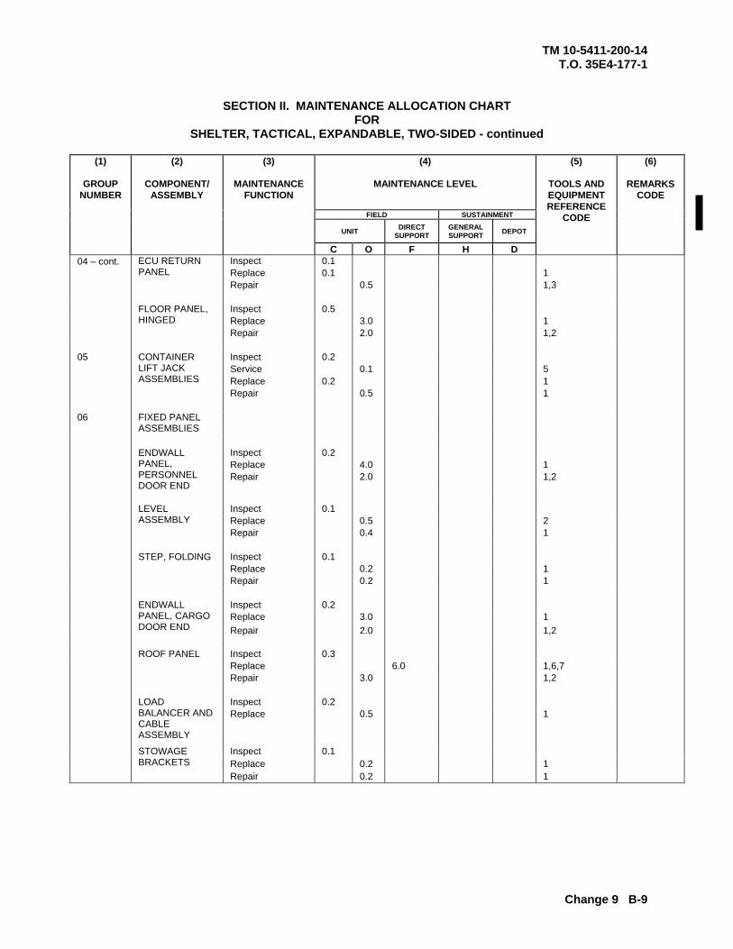
TM 10-5411-200-14 T.O. 35E4-177-1
Change 9 B-9
SECTION II. MAINTENANCE ALLOCATION CHART
FOR SHELTER, TACTICAL, EXPANDABLE, TWO-SIDED - continued
(4)
MAINTENANCE LEVEL
FIELD SUSTAINMENT
UNIT DIRECT SUPPORT
GENERAL SUPPORT DEPOT
(1)
GROUP NUMBER
(2)
COMPONENT/ ASSEMBLY
(3)
MAINTENANCE FUNCTION
C O F H D
(5)
TOOLS AND EQUIPMENT REFERENCE
CODE
(6)
REMARKS CODE
04 – cont. Inspect 0.1 Replace 0.1 1
ECU RETURN PANEL
Repair 0.5 1,3 Inspect 0.5 Replace 3.0 1
FLOOR PANEL, HINGED
Repair 2.0 1,2 05 Inspect 0.2 Service 0.1 5 Replace 0.2 1
CONTAINER LIFT JACK ASSEMBLIES
Repair 0.5 1 06
FIXED PANEL ASSEMBLIES
Inspect 0.2 Replace 4.0 1
ENDWALL PANEL, PERSONNEL DOOR END
Repair 2.0 1,2
Inspect 0.1 Replace 0.5 2
LEVEL ASSEMBLY
Repair 0.4 1 Inspect 0.1 Replace 0.2 1
STEP, FOLDING
Repair 0.2 1 Inspect 0.2 Replace 3.0 1
ENDWALL PANEL, CARGO DOOR END Repair 2.0 1,2
Inspect 0.3 Replace 6.0 1,6,7
ROOF PANEL
Repair 3.0 1,2 Inspect 0.2 Replace 0.5 1
LOAD BALANCER AND CABLE ASSEMBLY
Inspect 0.1 Replace 0.2 1
STOWAGE BRACKETS
Repair 0.2 1
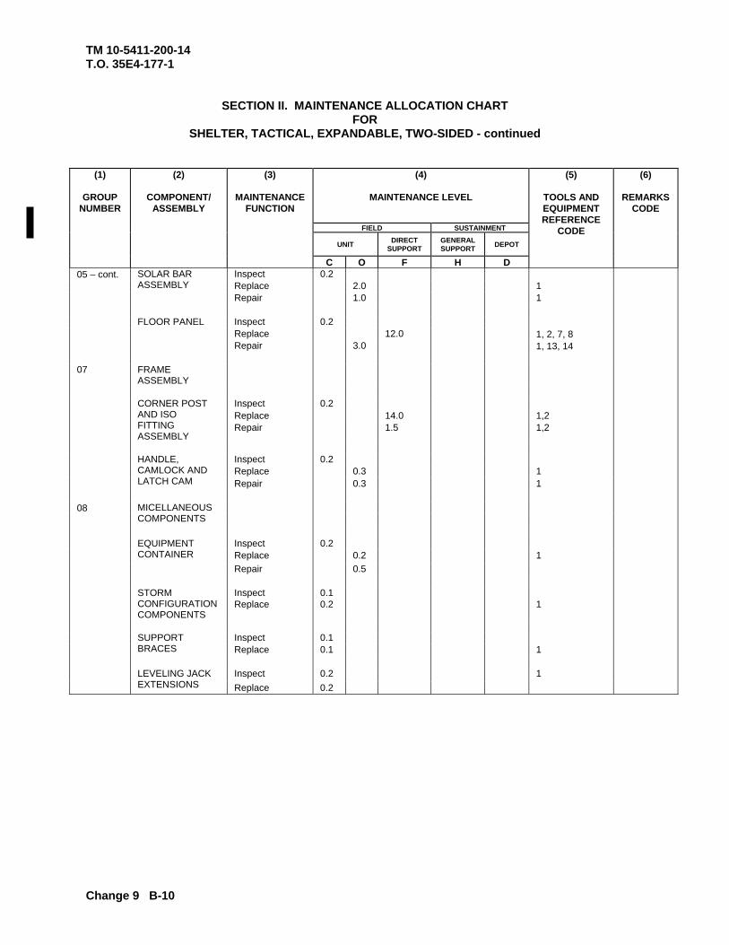
TM 10-5411-200-14 T.O. 35E4-177-1
Change 9 B-10
SECTION II. MAINTENANCE ALLOCATION CHART FOR
SHELTER, TACTICAL, EXPANDABLE, TWO-SIDED - continued
(4)
MAINTENANCE LEVEL FIELD SUSTAINMENT
UNIT DIRECT SUPPORT
GENERAL SUPPORT DEPOT
(1)
GROUP NUMBER
(2)
COMPONENT/ ASSEMBLY
(3)
MAINTENANCE FUNCTION
C O F H D
(5)
TOOLS AND EQUIPMENT REFERENCE
CODE
(6)
REMARKS CODE
05 – cont. Inspect 0.2 Replace 2.0 1
SOLAR BAR ASSEMBLY
Repair 1.0 1 Inspect 0.2 Replace 12.0 1, 2, 7, 8
FLOOR PANEL
Repair 3.0 1, 13, 14 07 FRAME
ASSEMBLY
Inspect 0.2 Replace 14.0 1,2
CORNER POST AND ISO FITTING ASSEMBLY
Repair 1.5 1,2 Inspect 0.2 Replace 0.3 1
HANDLE, CAMLOCK AND LATCH CAM Repair 0.3 1
08
MICELLANEOUS COMPONENTS
Inspect 0.2 Replace 0.2 1
EQUIPMENT CONTAINER
Repair 0.5 Inspect 0.1
STORM CONFIGURATION COMPONENTS
Replace 0.2 1
Inspect 0.1
SUPPORT BRACES Replace 0.1 1
Inspect 0.2 1
LEVELING JACK EXTENSIONS Replace 0.2
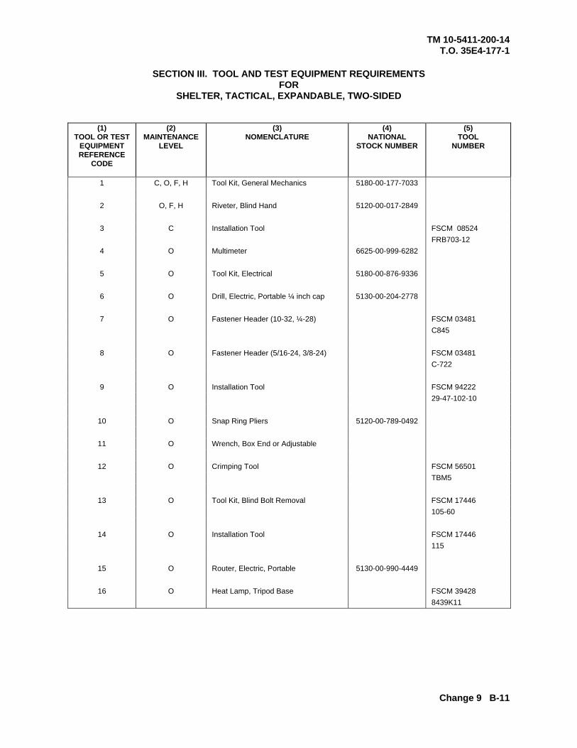
TM 10-5411-200-14 T.O. 35E4-177-1
Change 9 B-11
SECTION III. TOOL AND TEST EQUIPMENT REQUIREMENTS
FOR SHELTER, TACTICAL, EXPANDABLE, TWO-SIDED
(1) TOOL OR TEST
EQUIPMENT REFERENCE
CODE
(2) MAINTENANCE
LEVEL
(3) NOMENCLATURE
(4) NATIONAL
STOCK NUMBER
(5) TOOL
NUMBER
1 C, O, F, H Tool Kit, General Mechanics 5180-00-177-7033
2 O, F, H Riveter, Blind Hand 5120-00-017-2849
3 C Installation Tool FSCM 08524 FRB703-12
4 O Multimeter 6625-00-999-6282
5 O Tool Kit, Electrical 5180-00-876-9336
6 O Drill, Electric, Portable ¼ inch cap 5130-00-204-2778
7 O Fastener Header (10-32, ¼-28) FSCM 03481 C845
8 O Fastener Header (5/16-24, 3/8-24) FSCM 03481 C-722
9 O Installation Tool FSCM 94222 29-47-102-10
10 O Snap Ring Pliers 5120-00-789-0492
11 O Wrench, Box End or Adjustable
12 O Crimping Tool FSCM 56501 TBM5
13 O Tool Kit, Blind Bolt Removal FSCM 17446 105-60
14 O Installation Tool FSCM 17446 115
15 O Router, Electric, Portable 5130-00-990-4449
16 O Heat Lamp, Tripod Base FSCM 39428 8439K11

TM 10-5411-200-14 T.O. 35E4-177-1
Change 9 B-12
SECTION IV. REMARKS
FOR SHELTER, TACTICAL, EXPANDABLE, TWO-SIDED
(1) REMARKS
CODE
(2) REMARKS
Not applicable
TM 10-5411-200-14T.O. 35E4-177-1
APPENDIX C
COMPONENTS OF THE END ITEM LIST
Section I. INTRODUCTIONC-1. SCOPE
This appendix lists components of end item for the shelter to help you inventoryitems required for safe and efficient operation.
C-2. GENERAL
The Components of End Item List is provided in Section II. This listing is forinformational purposes only, and is not authority to requisition replacements.These items are part of the end item, but are removed and separately packagedfor transportation or shipment. As part of the end item, these items must bewith the end item whenever it is issued or transferred between propertyaccounts. Illustrations are furnished to assist you in identifying the items.
C-3. EXPLANATION OF COLUMNS IN SECTION II
The following provides an explanation of columns found in the tabular listings:
a. Column (1) - Illustration Number (Illus Number). This columnindicates the number of the illustration in which the item is shown.
b. Column (2) - National Stock Number. Indicates the National stocknumber assigned to the item and will be used for requisitioning purposes.
c* Column (3) - Description. Indicates the Federal item name and, ifrequired, a minimum description to identify and locate the item. The last linefor each item indicates the FSCM (in parentheses) followed by the part number.
d. Column (4) - Unit of Measure (U/M). Indicates the measure used inperforming the actual operational/maintenance function. This measure isexpressed by a two-character alphabetical abbreviation (e.g., ea, in, pr) .
e. Column (5) - Quantity required (Qty rqr). Indicates the quantity ofthe item authorized to be used with/on the equipment.
C-1
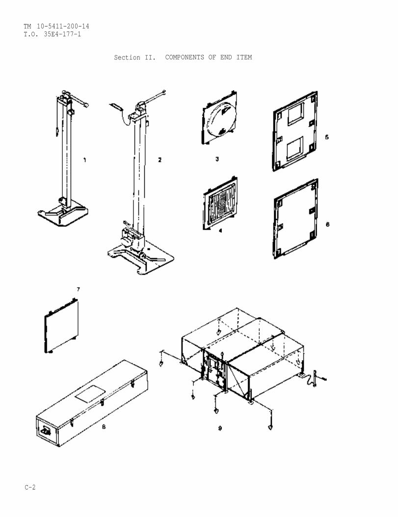
TM 10-5411-200-14T.O. 35E4-177-1
Section II. COMPONENTS OF END ITEM
C-2
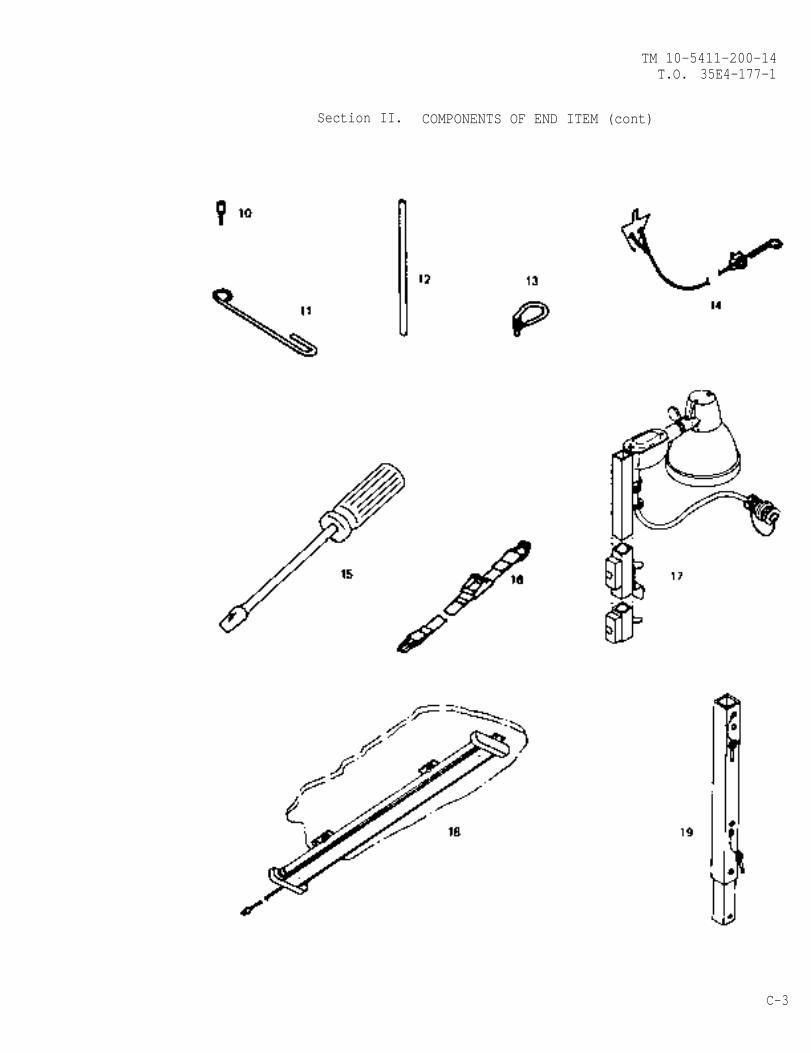
TM 10-5411-200-14T.O. 35E4-177-1
Section II. COMPONENTS OF END ITEM (cont)
C-3
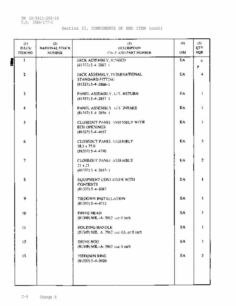
TM 1O-5411-200-14T.O. 35E4-177-1
Section II. COMPONENTS OF END ITEM (cont)
C-4 Change 6
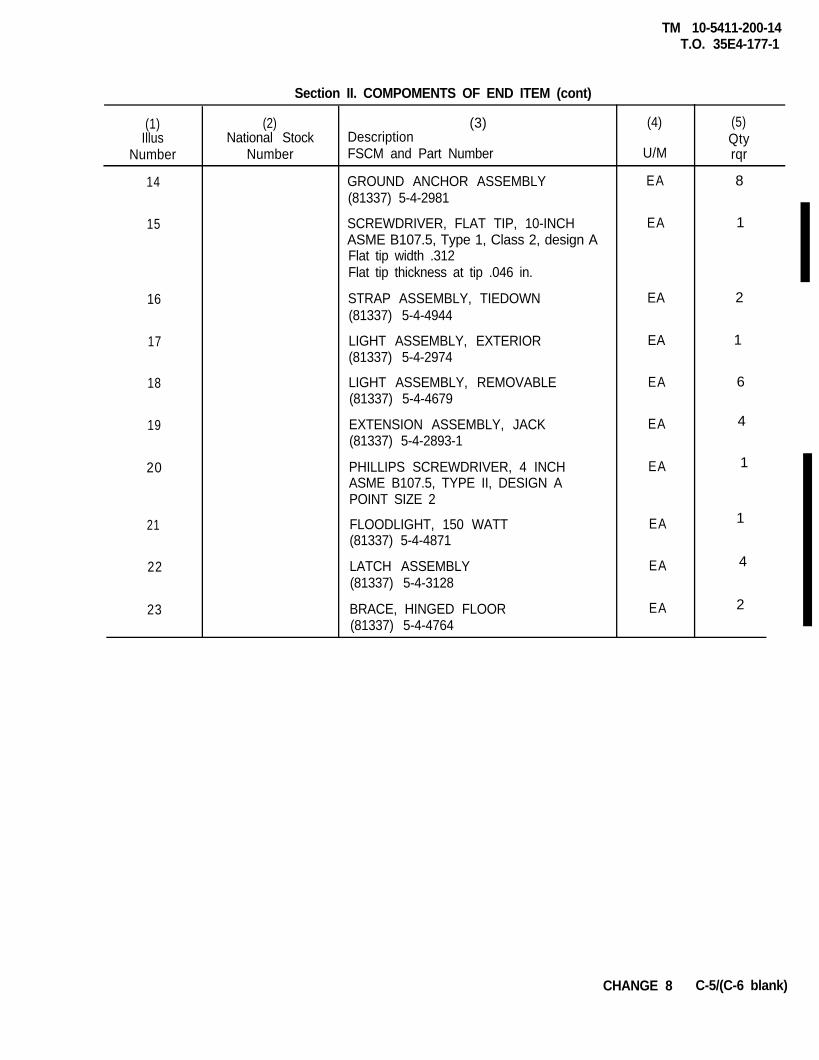
TM 10-5411-200-14T.O. 35E4-177-1
(1) (2) (3)Illus National Stock Description
Number Number FSCM and Part Number
14
15
16
17
18
19
20
4
1
1
4
2
21
22
23
Section II. COMPOMENTS OF END ITEM (cont)
GROUND ANCHOR ASSEMBLY(81337) 5-4-2981
SCREWDRIVER, FLAT TIP, 10-INCHASME B107.5, Type 1, Class 2, design AFlat tip width .312Flat tip thickness at tip .046 in.
STRAP ASSEMBLY, TIEDOWN(81337) 5-4-4944
LIGHT ASSEMBLY, EXTERIOR(81337) 5-4-2974
LIGHT ASSEMBLY, REMOVABLE(81337) 5-4-4679
EXTENSION ASSEMBLY, JACK(81337) 5-4-2893-1
PHILLIPS SCREWDRIVER, 4 INCHASME B107.5, TYPE II, DESIGN APOINT SIZE 2
FLOODLIGHT, 150 WATT(81337) 5-4-4871
LATCH ASSEMBLY(81337) 5-4-3128
BRACE, HINGED FLOOR(81337) 5-4-4764
(4)
U/M
EA 8
EA 1
EA 2
EA 1
EA 6
EA
EA
EA
EA
EA
(5)Qtyrqr
CHANGE 8 C-5/(C-6 blank)

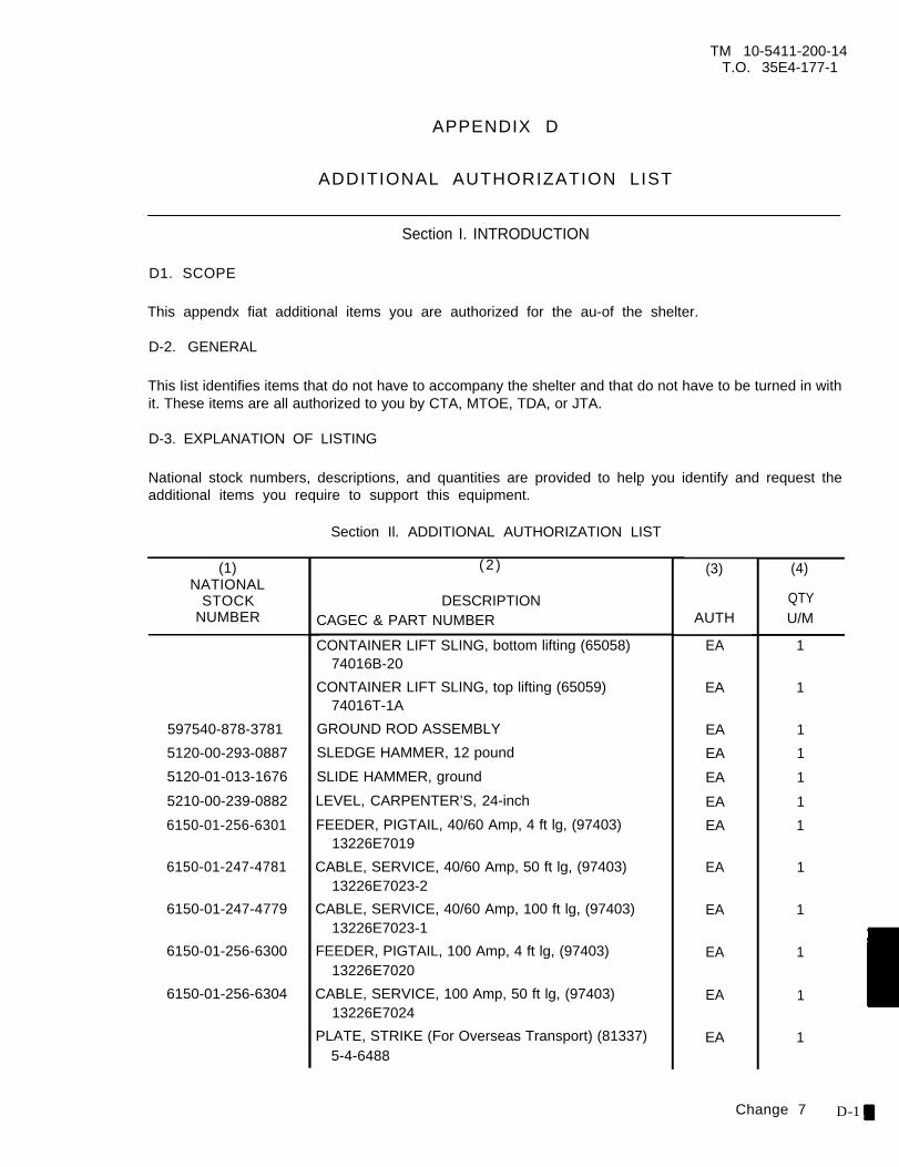
TM 10-5411-200-14T.O. 35E4-177-1
APPENDIX D
ADDITIONAL AUTHORIZATION LIST
Section I. INTRODUCTION
D1. SCOPE
This appendx fiat additional items you are authorized for the au-of the shelter.
D-2. GENERAL
This Iist identifies items that do not have to accompany the shelter and that do not have to be turned in withit. These items are all authorized to you by CTA, MTOE, TDA, or JTA.
D-3. EXPLANATION OF LISTING
National stock numbers, descriptions, and quantities are provided to help you identify and request theadditional items you require to support this equipment.
. .
Section Il. ADDITIONAL AUTHORIZATION LIST
(1)NATIONAL
STOCKNUMBER
(2)
QTY
597540-878-3781
5120-00-293-0887
5120-01-013-1676
5210-00-239-0882
6150-01-256-6301
6150-01-247-4781
6150-01-247-4779
6150-01-256-6300
6150-01-256-6304
DESCRIPTIONCAGEC & PART NUMBER
CONTAINER LIFT SLING, bottom lifting (65058)74016B-20
CONTAINER LIFT SLING, top lifting (65059)74016T-1A
GROUND ROD ASSEMBLY
SLEDGE HAMMER, 12 pound
SLIDE HAMMER, ground
LEVEL, CARPENTER’S, 24-inch
FEEDER, PIGTAIL, 40/60 Amp, 4 ft lg, (97403)13226E7019
CABLE, SERVICE, 40/60 Amp, 50 ft lg, (97403)13226E7023-2
CABLE, SERVICE, 40/60 Amp, 100 ft lg, (97403)13226E7023-1
FEEDER, PIGTAIL, 100 Amp, 4 ft lg, (97403)13226E7020
CABLE, SERVICE, 100 Amp, 50 ft lg, (97403)13226E7024
PLATE, STRIKE (For Overseas Transport) (81337)5-4-6488
(3)
AUTH
EA
EA
EA
EA
EA
EA
EA
EA
EA
EA
EA
EA
(4)
U/M
1
1
1
1
1
1
1
1
1
1
1
1
Change 7 D-1
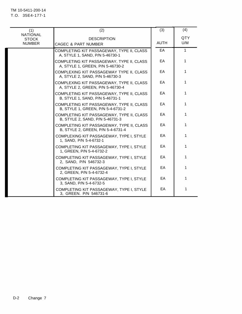
TM 10-5411-200-14T.O. 35E4-177-1
(1)NATIONAL
STOCKNUMBER
(2)
DESCRIPTIONCAGEC & PART NUMBER
QTY
COMPLETING KIT PASSAGEWAY, TYPE II, CLASSA, STYLE 1, SAND, P/N 5-46730-1
COMPLETING KIT PASSAGEWAY, TYPE II, CLASSA, STYLE 1, GREEN, P/N 5-46730-2
COMPLEXING KIT PASSAGEWAY TYPE II, CLASSA, STYLE 2, SAND, P/N 5-46730-3
COMPLEXlNG KIT PASSAGEWAY, TYPE II, CLASSA, STYLE 2, GREEN, P/N 5-46730-4
COMPLETING KIT PASSAGEWAY, TYPE II, CLASSB, STYLE 1, SAND, P/N 5-46731-1
COMPLETING KIT PASSAGEWAY, TYPE II, CLASSB, STYLE 1, GREEN, P/N 5-4-6731-2
COMPLETING KIT PASSAGEWAY, TYPE II, CLASSB, STYLE 2, SAND, P/N 5-46731-3
COMPLETING KIT PASSAGEWAY, TYPE II, CLASSB, STYLE 2, GREEN, P/N 5-4-6731-4
COMPLEXING KIT PASSAGEWAY, TYPE I, STYLE1, SAND, P/N 5-4-6732-1
COMPLETING KIT PASSAGEWAY, TYPE I, STYLE1, GREEN, P/N 5-4-6732-2
COMPLETING KIT PASSAGEWAY, TYPE I, STYLE2, SAND, P/N 546732-3
COMPLETING KIT PASSAGEWAY, TYPE I, STYLE2, GREEN, P/N 5-4-6732-4
COMPLETING KIT PASSAGEWAY, TYPE I, STYLE3, SAND, P/N 5-4-6732-5
COMPLETING KIT PASSAGEWAY, TYPE I, STYLE3, GREEN. P/N 546731-6
(3)
AUTH
EA
EA
EA
EA
EA
EA
EA
EA
EA
EA
EA
EA
EA
EA
(4)
U/M
1
1
1
1
1
1
1
1
1
1
1
1
1
1
D-2 Change 7
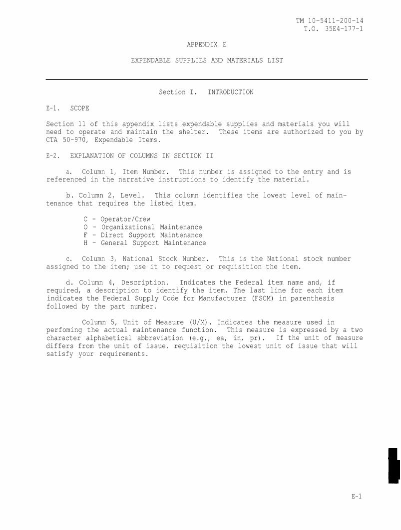
TM 10-5411-200-14T.O. 35E4-177-1
APPENDIX E
EXPENDABLE SUPPLIES AND MATERIALS LIST
Section I. INTRODUCTION
E-1. SCOPE
Section 11 of this appendix lists expendable supplies and materials you willneed to operate and maintain the shelter. These items are authorized to you byCTA 50-970, Expendable Items.
E-2. EXPLANATION OF COLUMNS IN SECTION II
a. Column 1, Item Number. This number is assigned to the entry and isreferenced in the narrative instructions to identify the material.
b. Column 2, Level. This column identifies the lowest level of main-tenance that requires the listed item.
C - Operator/CrewO - Organizational MaintenanceF - Direct Support MaintenanceH - General Support Maintenance
c. Column 3, National Stock Number. This is the National stock numberassigned to the item; use it to request or requisition the item.
d. Column 4, Description. Indicates the Federal item name and, ifrequired, a description to identify the item. The last line for each itemindicates the Federal Supply Code for Manufacturer (FSCM) in parenthesisfollowed by the part number.
Column 5, Unit of Measure (U/M). Indicates the measure used inperfoming the actual maintenance function. This measure is expressed by a twocharacter alphabetical abbreviation (e.g., ea, in, pr). If the unit of measurediffers from the unit of issue, requisition the lowest unit of issue that willsatisfy your requirements.
E-1
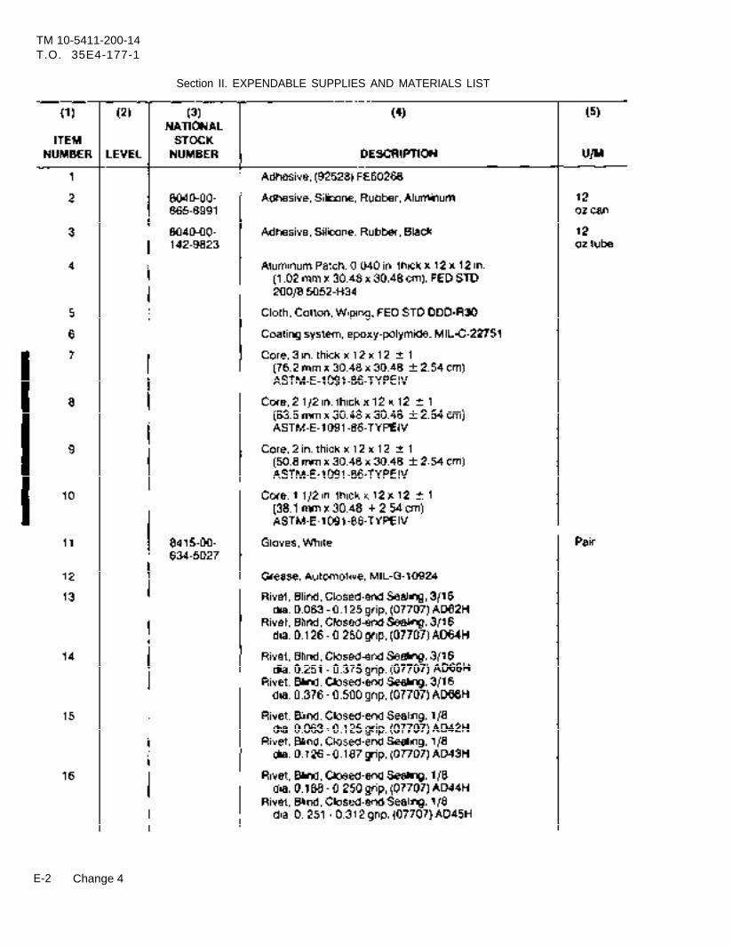
TM 10-5411-200-14T.O. 35E4-177-1
Section II. EXPENDABLE SUPPLIES AND MATERIALS LIST
E-2 Change 4
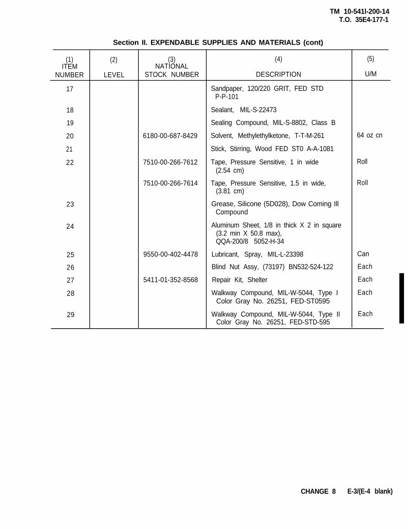
TM 10-541l-200-14T.O. 35E4-177-1
(1)ITEM
NUMBER
17
18
19
20
21
22
23
24
25
26
27
28
29
(2)
Section II. EXPENDABLE SUPPLIES AND MATERIALS (cont)
(3) (4)NATIONAL
STOCK NUMBER DESCRIPTION
Sandpaper, 120/220 GRIT, FED STDP-P-101
LEVEL
Sealant, MIL-S-22473
Sealing Compound, MIL-S-8802, Class B
6180-00-687-8429 Solvent, Methylethylketone, T-T-M-261
Stick, Stirring, Wood FED ST0 A-A-1081
7510-00-266-7612 Tape, Pressure Sensitive, 1 in wide(2.54 cm)
7510-00-266-7614 Tape, Pressure Sensitive, 1.5 in wide,(3.81 cm)
9550-00-402-4478
5411-01-352-8568
Grease, Silicone (5D028), Dow Coming IllCompound
Aluminum Sheet, 1/8 in thick X 2 in square(3.2 min X 50.8 max),QQA-200/8 5052-H-34
Lubricant, Spray, MIL-L-23398
Blind Nut Assy, (73197) BN532-524-122
Repair Kit, Shelter
Walkway Compound, MIL-W-5044, Type IColor Gray No. 26251, FED-ST0595
Walkway Compound, MIL-W-5044, Type IIColor Gray No. 26251, FED-STD-595
(5)
U/M
64 oz cn
Roll
Roll
Can
Each
Each
Each
Each
CHANGE 8 E-3/(E-4 blank)

TM 10-5411-200-14T.O. 35E4-177-1
INDEX
Subject Paragraph,Figure, Table
Number
A
Administrative StorageArea Light Assembly ReplacementArea Light Assembly Testing and RepairArea Light Installation
B
Blackout Switch Replacement Repair, and AdjustmentBlind Rivet Removal and Installation
C
Camlock and Latch Cam Handle Replacement and RepairCargo Door End Endwall Panel Replacement and RepairCaulking Repaired AreasCeiling Lights and Utility Outlets InstallationCircuit Breaker Panel Assembly Replacement and RepairCircuit Breaker Panel Assembly Testing, Replacement and RepairCircuit Breaker Panel Controls and IndicatorsClosing SequenceCommon Tools and EquipmentContainer Lift Jack Assembly ReplacementContainer Lift Jack Assembly Service and RepairCorner Post and ISO Fitting Assembly Replacement and Repair
D
Decal Removal and ReplacementDestruction of Materiel to Prevent Enemy UseDrying Water Soaked Areas in Panels
E
Electrical System Schematic Diagram - 60 Amp ServiceElectrical System Schematic Diagram - 100 Amp ServiceEndwall Closeout Panel ReplacementEquipment Container Replacement and RepairEquipment DataExplanation of Columns in Section IIExplanation of Columns in Section IIIExternal Connections
1 -43 - 44-92-14
4-154-32
4-294-264-422-135-24-7, 4-7.12-2
4-12-16
3-94-245-5
4-441-34-31
4-454-473-74-30
B-2, C-2, E-2B-32-15
1 -9
CHANGE 2 Index 1
TM 10-5411-200-14T.O. 35E4-177-1
INDEX (continued)
Subject
FieldFixedFloorFloorForms
F
ManualsRoof Area Ceiling Light Testing, Replacement and RepairPanel RepairPanel Replacement
General
H
Hinged Endwall Replacement and RepairHinged Floor Panel Replacement and RepairHinged Panel Leveling Jack Assembly ReplacementHinged Panel Leveling Jack Assembly Service and RepairHinged Roof Area Ceiling Light ReplacementHinged Roof Area Ceiling Light Testing and RepairHinged Roof Panel Service, Replacement, Repair and AlignmentHinged Sidewall Replacement
Incandescent Light Assembly
and Repair
I
Testing, Replacement and Repair
L
Left Cargo Door Replacement, Repair and AlignmentList of AbbreviationsLocation and Description of Major ComponentsLocation of Identification and Instruction PlatesMaintenance Forms, Records, and Reports
O
Operating InstructionsOperation During Blackout ConditionsOperation In High WindsOperation In Rain and/or MudOperation In Snow, Ice or Extreme ColdOperator TroubleshootingOrganizational Maintenance Troubleshooting
Paragraph,Figure, Table
Number
A-34-124-286-2A-2
2-4, 2-183-1, 3-34-4, 5-16-1, C-2
4-214-233-64-193-54-114-204-22
4-10
4-181-61-82-111-2
2-172-222-212-192-203-24-6
Index 2
TM 10-5411-200-14T.O. 35E4-177-1
INDEX (continued)
Subject Paragraph,Figure, Table
Number
P.
Paint RefinishingPersonnel and Right Cargo Door Replacement, Repair andAlignmentPersonnel Door End Endwall Panel Replacement and RepairPersonnel End Panel Mounted Controls and IndicatorsPower Entry Panel Assembly Replacement and RepairPower Entry Panel Assembly Testing, Replacement, and RepairPreparation For Storage and ShipmentPreparation For UsePreventive Maintenance Checks and Services TablePurpose of Two-Sided Expandable Tactical Shelter Assembly
R
Receptacle Outlets Testing, Replacement and RepairRepair ofRepair ofRepair ofRepair ofRepair ofRepair ofRepair of
Damage With Extended CracksDepression or Small PuncturePuncture Through Both Skins and CorePuncture Through One Skin and CorePuncture With Core FracturePuncture With Minimal Damage to CoreSmall Dent or Depression
Repair PartsReplacement of Obsolete NQOB Circuit Breaker Panel With
New NQOD Circuit Breaker PanelReporting Equipment Improvement Recommendations (EIR’s)Roof Panel Assembly RepairRoof Panel Replacement
SSchematicsScope
Shelter Body Seals ReplacementShelter ExpansionShelter HandlingShelter Inspection ChecklistShelter Inventory ChecksSidewall Closeout, ECU Intake, and ECU Return PanelsReplacement
Special Instructions
4-43
4-174-252-35-34-84-492-72-61-7
4-134-374-344-394-384-364-354-334-3
4-7.11-54-275-4
4-45, 4-471-1, 2-1, A-1B-1, C-1, E-14-402-122-102-92-8
3-82-5
CHANGE 2 Index 3
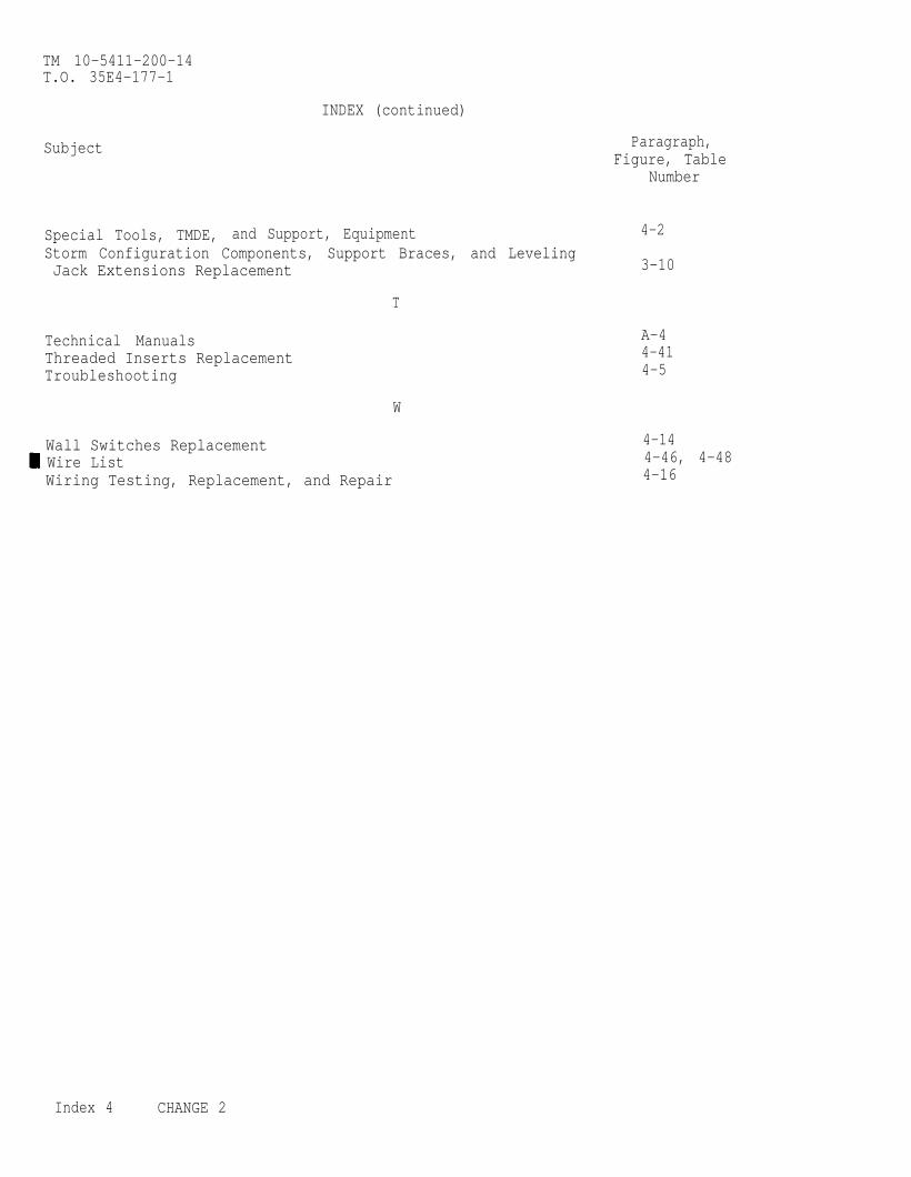
TM 10-5411-200-14T.O. 35E4-177-1
INDEX (continued)
Subject
Special Tools, TMDE, and Support, EquipmentStorm Configuration Components, Support Braces, and LevelingJack Extensions Replacement
T
Technical ManualsThreaded Inserts ReplacementTroubleshooting
W
Wall Switches Replacement Wire ListWiring Testing, Replacement, and Repair
Paragraph,Figure, Table
Number
4-2
3-10
A-44-414-5
4-144-46, 4-484-16
Index 4 CHANGE 2
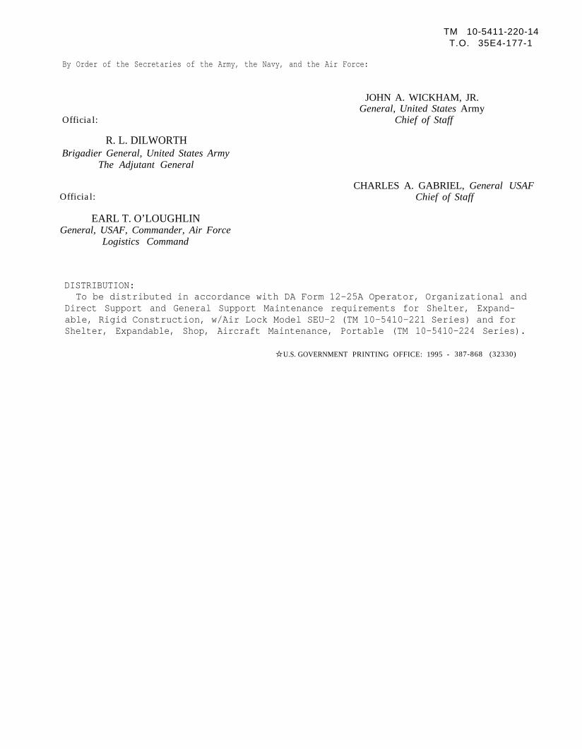
TM 10-5411-220-14T.O. 35E4-177-1
By Order of the Secretaries of the Army, the Navy, and the Air Force:
Official:
R. L. DILWORTHBrigadier General, United States Army
The Adjutant General
Official:
JOHN A. WICKHAM, JR.General, United States Army
Chief of Staff
CHARLES A. GABRIEL, General USAFChief of Staff
EARL T. O’LOUGHLINGeneral, USAF, Commander, Air Force
Logistics Command
DISTRIBUTION:To be distributed in accordance with DA Form 12-25A Operator, Organizational and
Direct Support and General Support Maintenance requirements for Shelter, Expand-able, Rigid Construction, w/Air Lock Model SEU-2 (TM 10-5410-221 Series) and forShelter, Expandable, Shop, Aircraft Maintenance, Portable (TM 10-5410-224 Series).
✩ U.S. GOVERNMENT PRINTING OFFICE: 1995 - 387-868 (32330)


These are the instructions for sending an electronic 2028 The following format must be used if submitting an electronic 2028. The subject line must be exactly the same and all fields must be included; however, only the following fields are mandatory: 1, 3, 4, 5, 6, 7, 8, 9, 10, 13, 15, 16, 17, and 27. From: “Whomever” [email protected] To: [email protected] Subject: DA Form 2028 1. From: Joe Smith 2. Unit home 3. Address: 4300 Park 4. City: Hometown 5. St: MO 6. Zip: 77777 7. Date Sent: 19-OCT-93 8. Pub no: 55-2840-229-23 9. Pub Title: TM 10. Publication Date: 04-JUL-85 11. Change Number: 7 12. Submitter Rank: MSG 13. Submitter FName: Joe 14. Submitter MName: T 15. Submitter LName: Smith 16. Submitter Phone: 123-123-1234 17. Problem: 1 18. Page: 2 19. Paragraph: 3 20. Line: 4 21. NSN: 5 22. Reference: 6 23. Figure: 7 24. Table: 8 25. Item: 9 26. Total: 123 27. Text: This is the text for the problem below line 27.

RECOMMENDED CHANGES TO PUBLICATIONS AND BLANK FORMS
For use of this form, see AR 25-30; the proponent agency is ODISC4.
Use Part II (reverse) for Repair Parts and Special Tool Lists (RPSTL) and Supply Catalogs/Supply Manuals (SC/SM).
DATE
21 October 2003
TO: (Forward to proponent of publication or form) (Include ZIP Code) COMMANDER U.S. ARMY TANK-AUTOMOTIVE AND ARMAMENT COMMAND ATTN: AMSTA-LC-CECT 15 KANSAS STREET NATICK, MA 01760-5052
FROM: (Activity and location) (Include ZIP Code) PFC Jane Doe CO A 3rd Engineer BR Ft. Leonardwood, MO 63108
PART I – ALL PUBLICATIONS (EXCEPT RPSTL AND SC/SM) AND BLANK FORMS PUBLICATION/FORM NUMBER TM 10-1670-296-23&P
DATE 30 October 2002
TITLE Unit Manual for Ancillary Equipment for Low Velocity Air Drop Systems
ITEM NO.
PAGE NO.
PARA- GRAPH
LINE NO. *
FIGURE NO.
TABLE NO.
RECOMMENDED CHANGES AND REASON (Provide exact wording of recommended changes, if possible).
0036 00-2
1
In table 1, Sewing Machine Code Symbols, the second sewing machine code symbol should be MD ZZ not MD 22. Change the manual to show Sewing Machine, Industrial: Zig-Zag; 308 stitch; medium-duty; NSN 3530-01-181-1421 as a MD ZZ code symbol.
*Reference to line numbers within the paragraph or subparagraph. TYPED NAME, GRADE OR TITLE Jane Doe, PFC
TELEPHONE EXCHANGE/AUTOVON, PLUS EXTENSION 508-233-4141
SIGNATURE
Jane Doe Jane Doe
DA FORM 2028, FEB 74 REPLACES DA FORM 2028, 1 DEC 68, WHICH WILL BE USED. USAPPC V3.00
TO: (Forward direct to addressee listed in publication) COMMANDER U.S. ARMY TANK-AUTOMOTIVE AND ARMAMENT COMMAND ATTN: AMSTA-LC-CECT 15 KANSAS STREET NATICK, MA 01760-5052
FROM: (Activity and location) (Include ZIP Code) PFC Jane Doe CO A 3rd Engineer BR Ft. Leonardwood, MO 63108
DATE 21 October 2003
PART II – REPAIR PARTS AND SPECIAL TOOL LISTS AND SUPPLY CATALOGS/SUPPLY MANUALS PUBLICATION NUMBER TM 10-1670-296-23&P
DATE 30 October 2002
TITLE Unit Manual for Ancillary Equipment for Low Velocity Air Drop Systems
PAGE NO.
COLM
NO.
LINE NO.
NATIONAL
STOCK NUMBER
REFERENCE
NO.
FIGURE
NO.
ITEM NO.
TOTAL NO. OF MAJOR ITEMS SUPPORTED
RECOMMENDED ACTION 0066 00-1
4
Callout 16 in figure 4 is pointed to a D-Ring. In the Repair Parts List key for figure 4, item 16 is called a Snap Hook. Please correct one or the other.
PART III – REMARKS (Any general remarks or recommendations, or suggestions for improvement of publications and blank forms. Additional blank sheets may be used if more space is needed.)
TYPED NAME, GRADE OR TITLE
TELEPHONE EXCHANGE/AUTOVON, PLUS EXTENSION
SIGNATURE
UASPPC V3.00
RECOMMENDED CHANGES TO PUBLICATIONS AND BLANK FORMS
For use of this form, see AR 25-30; the proponent agency is ODISC4.
Use Part II (reverse) for Repair Parts and Special Tool Lists (RPSTL) and Supply Catalogs/Supply Manuals (SC/SM).
DATE
TO: (Forward to proponent of publication or form) (Include ZIP Code) COMMANDER U.S. ARMYTANK-AUTOMOTIVE AND ARMAMENT COMMAND ATTN: AMSTA-LC-CECT 15 KANSAS STREET NATICK, MA 01760-5052
FROM: (Activity and location) (Include ZIP Code)
PART I – ALL PUBLICATIONS (EXCEPT RPSTL AND SC/SM) AND BLANK FORMS PUBLICATION/FORM NUMBER TM 10-5411-200-14
DATE 1 April 1986
TITLE Shelter, Tactical Expandable, Two-Sided
ITEM NO.
PAGE NO.
PARA- GRAPH
LINE NO. *
FIGURE NO.
TABLE NO.
RECOMMENDED CHANGES AND REASON (Provide exact wording of recommended changes, if possible).
*Reference to line numbers within the paragraph or subparagraph. TYPED NAME, GRADE OR TITLE TELEPHONE EXCHANGE/AUTOVON, PLUS
EXTENSION SIGNATURE
DA FORM 2028, FEB 74 REPLACES DA FORM 2028, 1 DEC 68, WHICH WILL BE USED. USAPPC V3.00
TO: (Forward direct to addressee listed in publication) COMMANDER U.S. ARMYTANK-AUTOMOTIVE AND ARMAMENT COMMAND ATTN: AMSTA-LC-CECT 15 KANSAS STREET NATICK, MA 01760-5052
FROM: (Activity and location) (Include ZIP Code) DATE
PART II – REPAIR PARTS AND SPECIAL TOOL LISTS AND SUPPLY CATALOGS/SUPPLY MANUALS PUBLICATION NUMBER TM10-5411-200-14
DATE 1 April 1986
TITLE Shelter, Tactical Expandable, Two-Sided
PAGE NO.
COLM
NO.
LINE NO.
NATIONAL STOCK
NUMBER
REFERENCE
NO.
FIGURE
NO.
ITEM NO.
TOTAL NO. OF MAJOR
ITEMS SUPPORTED
RECOMMENDED ACTION
PART III – REMARKS (Any general remarks or recommendations, or suggestions for improvement of publications and blank forms. Additional blank sheets may be used if more space is needed.)
TYPED NAME, GRADE OR TITLE TELEPHONE EXCHANGE/AUTOVON, PLUS EXTENSION SIGNATURE
UASPPC V3.00

RECOMMENDED CHANGES TO PUBLICATIONS AND BLANK FORMS
For use of this form, see AR 25-30; the proponent agency is ODISC4.
Use Part II (reverse) for Repair Parts and Special Tool Lists (RPSTL) and Supply Catalogs/Supply Manuals (SC/SM).
DATE
TO: (Forward to proponent of publication or form) (Include ZIP Code) COMMANDER U.S. ARMYTANK-AUTOMOTIVE AND ARMAMENT COMMAND ATTN: AMSTA-LC-CECT 15 KANSAS STREET NATICK, MA 01760-5052
FROM: (Activity and location) (Include ZIP Code)
PART I – ALL PUBLICATIONS (EXCEPT RPSTL AND SC/SM) AND BLANK FORMS PUBLICATION/FORM NUMBER TM 10-5411-200-14
DATE 1 April 1986
TITLE Shelter, Tactical Expandable, Two-Sided
ITEM NO.
PAGE NO.
PARA- GRAPH
LINE NO. *
FIGURE NO.
TABLE NO.
RECOMMENDED CHANGES AND REASON (Provide exact wording of recommended changes, if possible).
*Reference to line numbers within the paragraph or subparagraph. TYPED NAME, GRADE OR TITLE TELEPHONE EXCHANGE/AUTOVON, PLUS
EXTENSION SIGNATURE
DA FORM 2028, FEB 74 REPLACES DA FORM 2028, 1 DEC 68, WHICH WILL BE USED. USAPPC V3.00

TO: (Forward direct to addressee listed in publication) COMMANDER U.S. ARMYTANK-AUTOMOTIVE AND ARMAMENT COMMAND ATTN: AMSTA-LC-CECT 15 KANSAS STREET NATICK, MA 01760-5052
FROM: (Activity and location) (Include ZIP Code) DATE
PART II – REPAIR PARTS AND SPECIAL TOOL LISTS AND SUPPLY CATALOGS/SUPPLY MANUALS PUBLICATION NUMBER TM10-5411-200-14
DATE 1 April 1986
TITLE Shelter, Tactical Expandable, Two-Sided
PAGE NO.
COLM
NO.
LINE NO.
NATIONAL STOCK
NUMBER
REFERENCE
NO.
FIGURE
NO.
ITEM NO.
TOTAL NO. OF MAJOR
ITEMS SUPPORTED
RECOMMENDED ACTION
PART III – REMARKS (Any general remarks or recommendations, or suggestions for improvement of publications and blank forms. Additional blank sheets may be used if more space is needed.)
TYPED NAME, GRADE OR TITLE TELEPHONE EXCHANGE/AUTOVON, PLUS EXTENSION SIGNATURE
UASPPC V3.00
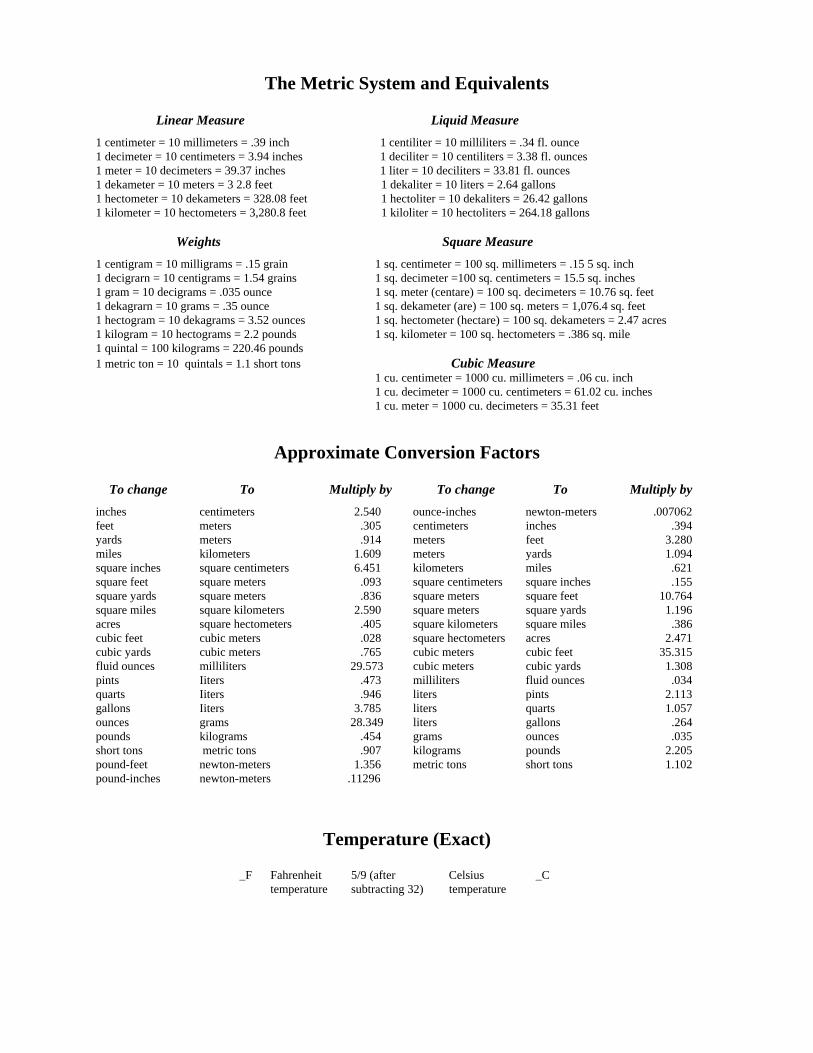
The Metric System and Equivalents Linear Measure Liquid Measure 1 centimeter = 10 millimeters = .39 inch 1 centiliter = 10 milliliters = .34 fl. ounce 1 decimeter = 10 centimeters = 3.94 inches 1 deciliter = 10 centiliters = 3.38 fl. ounces 1 meter = 10 decimeters = 39.37 inches 1 liter = 10 deciliters = 33.81 fl. ounces 1 dekameter = 10 meters = 3 2.8 feet 1 dekaliter = 10 liters = 2.64 gallons 1 hectometer = 10 dekameters = 328.08 feet 1 hectoliter = 10 dekaliters = 26.42 gallons 1 kilometer = 10 hectometers = 3,280.8 feet 1 kiloliter = 10 hectoliters = 264.18 gallons Weights Square Measure 1 centigram = 10 milligrams = .15 grain 1 sq. centimeter = 100 sq. millimeters = .15 5 sq. inch 1 decigrarn = 10 centigrams = 1.54 grains 1 sq. decimeter =100 sq. centimeters = 15.5 sq. inches 1 gram = 10 decigrams = .035 ounce 1 sq. meter (centare) = 100 sq. decimeters = 10.76 sq. feet 1 dekagrarn = 10 grams = .35 ounce 1 sq. dekameter (are) = 100 sq. meters = 1,076.4 sq. feet 1 hectogram = 10 dekagrams = 3.52 ounces 1 sq. hectometer (hectare) = 100 sq. dekameters = 2.47 acres 1 kilogram = 10 hectograms = 2.2 pounds 1 sq. kilometer = 100 sq. hectometers = .386 sq. mile 1 quintal = 100 kilograms = 220.46 pounds 1 metric ton = 10 quintals = 1.1 short tons Cubic Measure 1 cu. centimeter = 1000 cu. millimeters = .06 cu. inch 1 cu. decimeter = 1000 cu. centimeters = 61.02 cu. inches 1 cu. meter = 1000 cu. decimeters = 35.31 feet
Approximate Conversion Factors
To change To Multiply by To change To Multiply by inches centimeters 2.540 ounce-inches newton-meters .007062 feet meters .305 centimeters inches .394 yards meters .914 meters feet 3.280 miles kilometers 1.609 meters yards 1.094 square inches square centimeters 6.451 kilometers miles .621 square feet square meters .093 square centimeters square inches .155 square yards square meters .836 square meters square feet 10.764 square miles square kilometers 2.590 square meters square yards 1.196 acres square hectometers .405 square kilometers square miles .386 cubic feet cubic meters .028 square hectometers acres 2.471 cubic yards cubic meters .765 cubic meters cubic feet 35.315 fluid ounces milliliters 29.573 cubic meters cubic yards 1.308 pints Iiters .473 milliliters fluid ounces .034 quarts Iiters .946 liters pints 2.113 gallons Iiters 3.785 liters quarts 1.057 ounces grams 28.349 liters gallons .264 pounds kilograms .454 grams ounces .035 short tons metric tons .907 kilograms pounds 2.205 pound-feet newton-meters 1.356 metric tons short tons 1.102 pound-inches newton-meters .11296
Temperature (Exact)
_F Fahrenheit 5/9 (after Celsius _C temperature subtracting 32) temperature

P I N : 0 5 9 9 8 1 - 0 0 0